
Recent advances in photoelectrochemical hydrogen production using I–III–VI quantum dots
Hyo Cheol
Lee
a,
Ji Hye
Park
a,
Su-Il
In
 ab and
Jiwoong
Yang
*ab
ab and
Jiwoong
Yang
*ab
aDepartment of Energy Science and Engineering, Daegu Gyeongbuk Institute of Science and Technology (DGIST), Daegu 42988, Republic of Korea. E-mail: jiwoongyang@dgist.ac.kr
bEnergy Science and Engineering Research Center, Daegu Gyeongbuk Institute of Science and Technology (DGIST), Daegu 42988, Republic of Korea
First published on 26th April 2024
Abstract
Photoelectrochemical (PEC) water splitting, recognized for its potential in producing solar hydrogen through clean and sustainable methods, has gained considerable interest, particularly with the utilization of semiconductor nanocrystal quantum dots (QDs). This minireview focuses on recent advances in PEC hydrogen production using I–III–VI semiconductor QDs. The outstanding optical and electrical properties of I–III–VI QDs, which can be readily tuned by modifying their size, composition, and shape, along with an inherent non-toxic nature, make them highly promising for PEC applications. The performance of PEC devices using these QDs can be enhanced by various strategies, including ligand modification, defect engineering, doping, alloying, and core/shell heterostructure engineering. These approaches have notably improved the photocurrent densities for hydrogen production, achieving levels comparable to those of conventional heavy-metal-based counterparts. Finally, this review concludes by addressing the present challenges and future prospects of these QDs, underlining crucial steps for their practical applications in solar hydrogen production.
 Hyo Cheol Lee | Hyo Cheol Lee is a Ph.D. candidate in the Department of Energy Science and Engineering, Daegu Gyeongbuk Institute of Science and Technology (DGIST), Republic of Korea. He received his M.S. degree in 2023 from DGIST, Republic of Korea. His current research interest lies in synthesis of I–III–VI quantum dots and their application in photoelectrochemical hydrogen production. |
 Su-Il In | Su-Il In is currently working as a professor in the Department of Energy Science and Engineering, Daegu Gyeongbuk Institute of Science and Technology (DGIST), Republic of Korea. He received his Ph.D. degree in 2008 from the University of Cambridge, UK. He worked as a postdoctoral researcher at Technical University of Denmark and Penn State University (2008–2012) before joining DGIST. His research interest includes photoelectrochemical hydrogen production, photo/electrocatalytic CO2 conversion, betavoltaic cells, nano-bio hybrid technology, and microbial fuel cells. |
 Jiwoong Yang | Jiwoong Yang is an associate professor in the Department of Energy Science and Engineering, Daegu Gyeongbuk Institute of Science and Technology (DGIST), Republic of Korea. He received his B.S. (2011) and Ph.D. degrees (2016) from Seoul National University, Republic of Korea. He worked as a postdoctoral researcher at Lawrence Berkeley National Laboratory until 2019. His research interest is synthesis of quantum dots for energy and electronic device applications. |
1. Introduction
Recent environmental challenges, including the increased consumption of fossil fuels, excessive emission of greenhouse gases, and radical, unpredictable climatic changes, have increased the demand for clean and sustainable energy sources.1–5 Solar energy has emerged as a promising solution to these issues, owing to its environmental sustainability, abundant availability, and cost-effectiveness.6–13 Remarkably, the annual solar radiation reaching Earth exceeds the global annual energy consumption by over 7500 times. Within this context, photoelectrochemical (PEC) water splitting is emerging as an efficient, economical, and clean approach to harness solar energy for hydrogen production through water electrolysis.14–20 Furthermore, this method, integrating solar energy harvesting and water electrolysis in a single device, offers a simple and cost-effective device design, thus positioning it as a leading technology for next-generation energy systems.Typically, PEC devices consist of a working electrode, a counter electrode, and an electrolyte.14–16 The working electrode is a photoelectrode that absorbs sunlight and can be classified as a photoanode and photocathode depending on the reaction involves. For the last several decades, various materials have been developed for PEC photoelectrodes,21–25 because the proper selection of materials plays a crucial role in boosting PEC performance. Metal oxide materials, such as TiO2, ZnO, and BiVO4, have been preferred for PEC hydrogen production, because of their abundance, low cost, eco-friendliness, and stability.22–25 Moreover, their band alignment is favorable for hydrogen generation from water, making them important materials for PEC hydrogen production. However, their wide bandgaps reduce sunlight absorption range, limiting the solar-to-hydrogen conversion efficiency.
Colloidal semiconductor quantum dots (QDs), tiny nanoparticles with dimensions spanning just a few nanometers,26–31 exhibit unique size- and shape-dependent properties compared to their bulk counterparts resulting from quantum confinement effects.32–35 They have emerged as efficient and versatile sensitizers for the photoelectrodes (usually, photoanodes) of PEC devices due to several advantages: tunable bandgap, large light absorption coefficient, facile synthesis, ease of surface functionalization, and solution processability.15–19,36–38 The discussed drawbacks (i.e., limited light absorption range) of the conventional metal oxide photoanodes can be addressed by utilizing QDs. However, the development of QD-sensitized photoanodes have been predominantly involved with QDs containing heavy metals, such as Cd and Pb, because of their high efficiency and stability.39,40 The environmental and health risks associated with these heavy metals have raised significant concerns, thereby limiting the practical use of PEC devices that incorporate such toxic materials.19
Recently, substantial efforts have been directed towards replacing heavy metal-based QDs with environmentally benign alternatives such as I–III–VI semiconductor QDs.41–49 The development of I–III–VI QDs for PEC hydrogen production is accelerating through various approaches including defect engineering,50 alloying (cation),51,52 doping,53,54 alloying (anion),55 ligand modification,56,57 and core/shell heterostructures.58–64 This raises the demand for a state-of-the-art review article. Previous reviews have broadly covered general QD-based photoanodes,16–19 PEC devices with various sensitizer materials,14,15 or the synthesis and properties of I–III–VI QDs.46–49 For instance, Yang et al. have focused on light-emitting diodes,65 while Shishodia et al. have concentrated on photovoltaic cells using I–III–VI QDs.66 However, comprehensive reviews and summaries of recent progress in I–III–VI QDs specifically for PEC applications have been rarely reported.
Herein, we summarize the recent advances in PEC hydrogen generation using I–III–VI QDs. We commence by elucidating the fundamental working principles of QD-based PEC devices, highlighting the unique properties of I–III–VI QDs. The review then systematically explores various material design strategies that have been developed to improve their PEC hydrogen production. These examples are categorized into Cu-based and Ag-based I–III–VI QDs, including summaries of the PEC performances. Finally, the review concludes with discussions on current challenges and future perspectives in this field. Note that PEC photoanodes employing larger I–III–VI nanocrystals, which do not show the quantum-confined effect, are not included in this review.
2. Quantum dot-based PEC devices
Usually, QDs have been employed as sensitizers of metal oxide photoanodes in PEC hydrogen production (Fig. 1). By introducing QDs onto oxide semiconductor photoelectrodes, the light absorption range of PEC devices can be greatly extended, which is beneficial for enhancing the overall efficiency of PEC hydrogen generation. The working principle of QD-based PEC devices is as follows. (I) Upon illumination, QDs absorb photons, generating electron–hole pairs. (II) The photogenerated electrons are transferred from QDs to oxide semiconductor of photoanodes and then to the counter electrode via the external circuit, driven by a built-in voltage due to a potential difference, catalyzing the hydrogen evolution reaction. Simultaneously, photogenerated holes participate in the redox reaction within the electrolyte. (III) These processes facilitate the following redox reactions:| 4H+ + 4e− → 2H2 (at cathode) |
| 2H2O + 4h+ → 4H+ + O2 (at anode) |
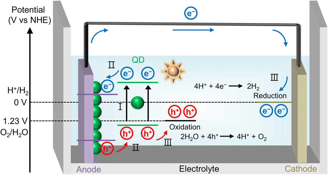 | ||
| Fig. 1 Schematic illustration depicting the general working principle of QD-based PEC devices. | ||
To achieve high performance PEC system, there are several key requirements for QD materials. (1) High absorption coefficient across a wide spectrum of solar energy. (2) Effective separation of electron–hole pairs and suppressed non-radiative recombination. (3) Effective charge transfer from QDs to oxide semiconductor of photoanodes.67–69 (4) Appropriate band alignment for the redox reactions. (5) Good stability under photon illumination and in aqueous environments.
I–III–VI semiconductor materials are typically classified into two categories based on the constituting Group I elements: Cu-based materials and Ag-based materials (Fig. 2a). The Group III elements include In and Ga, while the Group VI elements consist of S, Se, Te, among others. Generally, I–III–VI materials can exist in three crystal phases at room temperature: chalcopyrite, zinc blende, and wurtzite structures (Fig. 2b). Notably, in the zinc blende and wurtzite phases, the positions of I and III atoms are interchangeable. As sensitizers in the PEC hydrogen evolution system, I–III–VI QDs offer several advantages. Firstly, I–III–VI QDs exhibit bandgap tunability by controlling the QD size, allowing for facile adjustment of band alignment and light absorption, required in PEC systems (Fig. 2c). Secondly, the electrical properties of I–III–VI QDs can be modified by changing the elemental composition, primarily the ratio of I/III elements, which is a distinctive feature of I–III–VI QDs compared to other binary QDs (Fig. 2d).47,49–51
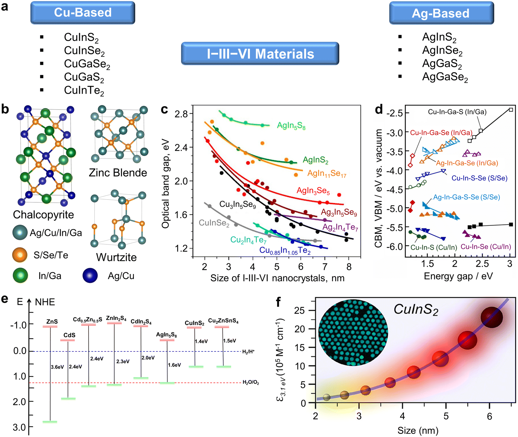 | ||
| Fig. 2 Characteristics of semiconductor I–III–VI materials. (a) Classification and representative examples of I–III–VI semiconductor materials. (b) Schematic illustration displaying crystal structures of I–III–VI materials. (c) Size-dependent bandgap of I–III–VI QDs. Adapted with permission from ref. 49. Copyright 2018, American Chemical Society. (d) Composition-dependent bandgap of I–III–VI materials. Adapted with permission from ref. 47. Copyright 2023, Elsevier. (e) Diagram showing the band alignment of representative bulk semiconductor materials. Adapted with permission from ref. 70. Copyright 2022, Wiley. (f) A graph showing size-dependent absorption coefficient of CuInS2 quantum dots. Adapted with permission from ref. 74. Copyright 2018, American Chemical Society. | ||
For effective PEC hydrogen generation using QD-based photoanodes, the electron transfer from QDs to metal oxide semiconductors of photoanodes (usually, TiO2) should be favorable. Fortunately, the band alignments of most I–III–VI QDs meet these criteria (Fig. 2e), making them highly suitable for PEC applications.70 As the quantum confinement effect broadens the bandgap, the band edges of I–III–VI QDs remain optimally positioned relative to photoanode materials with a relatively wide bandgap, facilitating swift electron transfer from QDs to metal oxide semiconductors and hole movement in the opposite direction. Practically, I–III–VI QDs have proven their efficiency in charge transfer characteristics for solar cell71,72 and photocatalytic hydrogen evolution applications.73 Furthermore, I–III–VI QDs exhibit a large absorption coefficient and a broad light absorption range that covers the visible to near-infrared wavelengths owing to their narrow bandgaps (Fig. 2f).74 This broad absorption spectrum aligns well with the significant portion of sunlight spectral distribution that reaches the Earth surface, primarily in the visible and near-infrared ranges,75 thereby enhancing the efficiency of PEC devices utilizing I–III–VI QDs.
In this minireview, we primarily evaluate PEC performance based on the photocurrent density. Photocurrent density (JPEC) is a crucial indicator of PEC hydrogen generation efficiency. It directly reflects the amount of electrical energy produced. Photocurrent density is determined using the following equation:14

3. Copper-based I–III–VI quantum dots
Among I–III–VI QDs, Cu-based I–III–VI QDs have been extensively studied for PEC and other applications. The properties of QDs are intrinsically related to their atomic structure. In other words, their properties can be regulated by structural modifications at the atomic scale although the morphology of QDs is similar at the nanometer scale. Li et al. demonstrated enhanced PEC performance by fine-tuning the In/Cu ratios in CuInSe2 (CISe) QDs.50 Through the careful modulation of Lewis acid–base reactions, it was possible to control the amount of copper vacancies in the CISe QDs without changing their morphology. The resulting QDs were In-rich, and their In/Cu ratios could be controlled from 1.29 to 1.83, depending on the acid strength of Cu and In precursors (Fig. 3a and b). CISe QDs with optimal In/Cu ratios (1.55 in this work) demonstrated excellent electrical properties, as indicated by increased carrier concentration and reduced trap density (Fig. 3c). Furthermore, these CISe QDs (In/Cu ratio = 1.55) exhibited a prolonged average carrier lifetime, which facilitates efficient charge carrier transfer. These synergistic characteristics resulted in the superior photocurrent density of 10.7 mA cm−2 (Fig. 3d). It is noteworthy that this enhancement can be achieved solely through controlling Cu defect concentration in QDs.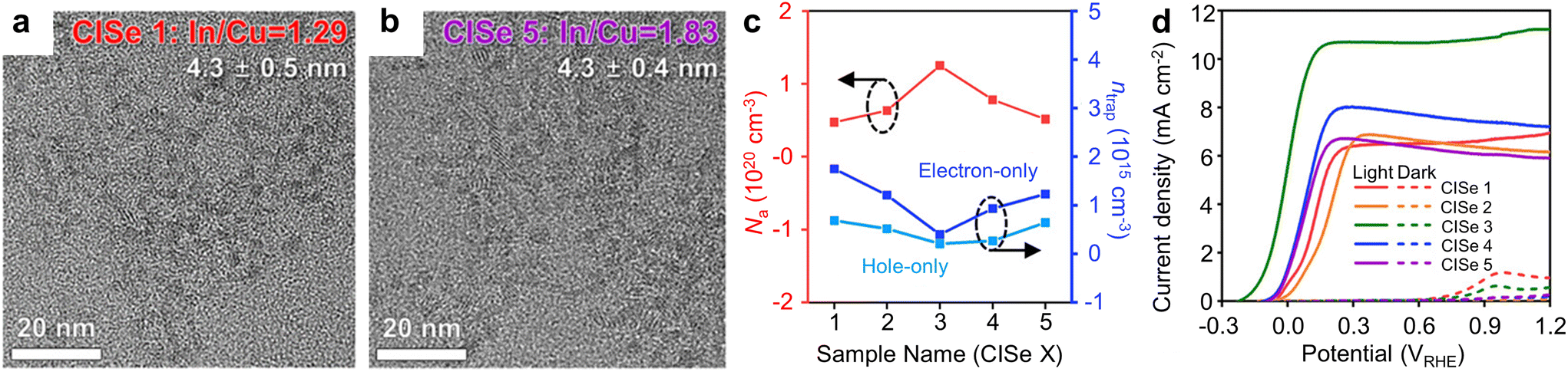 | ||
| Fig. 3 Defect engineering of Cu-based I–III–VI QDs for PEC hydrogen production. Transmission electron microscopy (TEM) images of CISe QDs with In/Cu ratio of (a) 1.29 and (b) 1.83. (c) Acceptor concentration (Na) and trap density (ntrap) of defect-engineered CISe QDs, and (d) their corresponding current–voltage (J–V) curves. Adapted with permission from ref. 50. Copyright 2023, Wiley. | ||
Meanwhile, introducing additional elements into QDs to create alloy or doped QDs has been proven as an effective approach in manipulating optical and electrical properties to enhance PEC performances. For instance, Liu et al. synthesized quaternary alloyed CuZnInS3 (CZIS) QDs, observing a blue shift in optical bandgaps with increasing Zn content (Fig. 4a).51 The resultant optical bandgaps of QDs with Cu![[thin space (1/6-em)]](https://www.rsc.org/images/entities/char_2009.gif) :Zn ratios of 1:0.5, 1:1, and 1:2 were estimated to be 2.0, 2.2, and 2.3 eV, respectively, indicating the successful formation of alloy structures. Alloying at a Cu:Zn ratio of 1:1 resulted in higher incident photon-to-electron conversion efficiencies (IPCE) for the visible light (380–560 nm) and a photocurrent density of 4.4 mA cm−2, attributable to a synergistic effect of the composition-tuned optical properties and carrier transfer dynamics of CZIS QDs (Fig. 4b).
:Zn ratios of 1:0.5, 1:1, and 1:2 were estimated to be 2.0, 2.2, and 2.3 eV, respectively, indicating the successful formation of alloy structures. Alloying at a Cu:Zn ratio of 1:1 resulted in higher incident photon-to-electron conversion efficiencies (IPCE) for the visible light (380–560 nm) and a photocurrent density of 4.4 mA cm−2, attributable to a synergistic effect of the composition-tuned optical properties and carrier transfer dynamics of CZIS QDs (Fig. 4b).
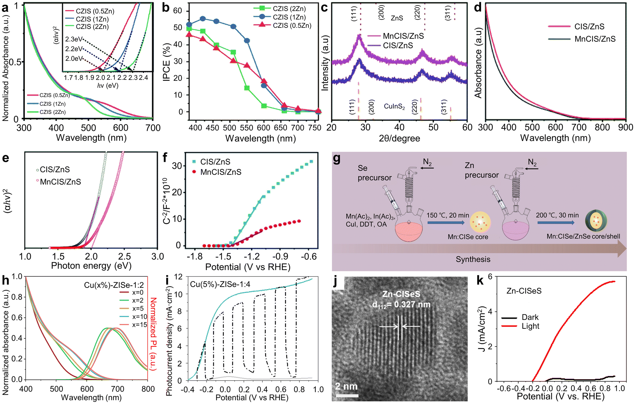 | ||
| Fig. 4 Cu-based I–III–VI QDs with additional elements for PEC hydrogen production. (a) Optical properties of CZIS alloyed QDs, and (b) IPCE curves of CZIS alloyed QD-based photoanodes. Adapted with permission from ref. 51. Copyright 2021, Royal Society of Chemistry. (c) XRD patterns, (d) absorption spectra, (e) Tauc plots, and (f) Mott–Schottky plots of CIS/ZnS and MnCIS/ZnS QDs. Adapted with permission from ref. 52. Copyright 2020, Royal Society of Chemistry. (g) Schematic illustration depicting the synthesis of Mn-doped CISe/ZnSe QDs. Adapted with permission from ref. 53. Copyright 2022, Springer. (h) Absorption and PL spectra of Cu-doped ZnInSe QDs with various Cu doping concentrations. (i) J–V curves of photoanodes with optimized Cu-doped ZnInSe QDs. Adapted with permission from ref. 54. Copyright 2021, Elsevier. (j) HR-TEM image of CISeS QDs. (k) J–V curves of CISeS/ZnS QD-based photoanodes. Adapted with permission from ref. 55. Copyright 2017, Elsevier. | ||
Wang et al. demonstrated the synthesis of Mn-alloyed CuInS2 (MnCIS)/ZnS core/shell QDs via the heat-up method and fabricated PEC cells based on these QDs.52 X-ray diffraction (XRD), X-ray photoelectron spectroscopy (XPS), and energy-dispersive X-ray (EDS) mapping results suggested successful alloying of the Mn element and its homogeneous distribution (Fig. 4c). Both MnCIS/ZnS and CIS/ZnS QDs exhibit a broad optical absorption range from approximately 300 nm to 700 nm (Fig. 4d). However, MnCIS/ZnS QDs have a wider bandgap compared to CIS/ZnS QDs (Fig. 4e). This wider bandgap positions the conduction band edge of MnCIS/ZnS QDs above that of TiO2, resulting in a more favorable band alignment. Furthermore, Mott–Schottky analysis indicates that MnCIS/ZnS QD-sensitized photoanodes possess a higher carrier concentration than their unalloyed counterparts, making them more effective for solar energy capture and enhancing charge transfer efficiency (Fig. 4f). The incorporation of Mn elements into CIS/ZnS QDs led to a reduction in charge carrier recombination, as evidenced by an increased carrier lifetime and decreased charge transfer resistance. The MnCIS/ZnS core/shell QD-sensitized photoanodes achieved a high photocurrent density up to 5.7 mA cm−2, coupled with exceptional device stability.
Meanwhile, Wang et al. explored the potential of Mn-doped CISe/ZnSe core/shell QDs in PEC systems, introducing Mn ions into the CISe core (Fig. 4g).53 They found that the band alignment of Mn dopant states, positioned at the conduction band edge between the CISe core and the ZnSe shell, facilitates electron delocalization and efficient charge carrier extraction. This finally resulted in a high photocurrent density of 6.0 mA cm−2.
Sometimes, the Cu element can be used as dopants in other ternary QDs. Luo et al. reported on Cu-doped ZnInSe QDs and their application in PEC photoanodes.54 They meticulously optimized the percentage of Cu ions (ranging from 0–15%) and the Zn:In atomic ratio (1:1, 1:2, 1:4, and 1:6) during the synthesis process to finely control the optical properties, band structure, charge carrier lifetime, and charge transport of the QDs. By varying the Cu molar ratio in ZnInSe QDs from 0% to 15%, they succeeded in adjusting the absorption edge from 547 nm to 647 nm (Fig. 4h). Specifically, Cu(5%):ZnInSe-1:4 QDs exhibited an extended charge carrier lifetime and more rapid charge carrier injection rates compared to undoped ZnInSe QDs. This enhancement in carrier dynamics for Cu(5%):ZnInSe-1:4 QDs promoted efficient electron/hole pair separation. As a result, PEC devices incorporating these optimized QDs (Cu(5%):ZnInSe-1:4) onto TiO2 achieved exceptional saturated photocurrent density values of approximately 11.23 mA cm−2 at 0.8 VRHE (Fig. 4i).
Alloying strategy can be applied for anion parts. Tong et al. reported the development of anion-alloyed CuInSexS2−x (CISeS) QDs, which serve as high-efficiency sensitizers in PEC devices.55 CISeS QDs were synthesized using a thermal decomposition method. High-resolution transmission electron microscopy (HR-TEM) measurements confirmed the alloyed composition (Fig. 4j). The PEC system utilizing the CISeS photoanode achieved a saturated photocurrent density of approximately 2.57 mA cm−2. To mitigate surface traps on bare CISeS QDs, a thin ZnS shell was formed on the core CISeS QDs through cation exchange. The refined PEC cell employing these core/shell CISeS/ZnS QDs exhibited decreased charge recombination, significantly enhancing stability and achieving a high saturated photocurrent density of around 5.3 mA cm−2 (Fig. 4k).
The modifications of QDs can be extended beyond the inorganic parts of QDs. The surface ligand modification, as a post-synthesis treatment, is crucial because they play a critical role in determining the properties of QDs. Park et al. investigated the effects of mono- and bifunctional surface ligands on PEC characteristics (Fig. 5a).56 CISe QDs with monofunctional ligands (oleylamine (OAm)-passivated QDs in this study) can be directly attached onto TiO2 through the partial detachment of the surface ligands. In contrast, bifunctional ligands (mercaptopropionic acids in this study) act as intermediate linkers between the QDs and TiO2. Thus, the QDs are connected to the TiO2via these ligands, rather than making direct contact. It was suggested that the direct contact was beneficial for the electron transport between the QDs and TiO2; therefore, monofunctional ligands were more favorable for efficient PEC hydrogen generation, evidenced by a notable photocurrent density of 8.2 mA cm−2 (Fig. 5b).
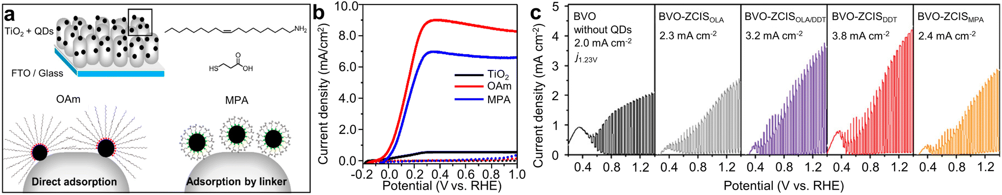 | ||
| Fig. 5 Ligand modification of Cu-based I–III–VI QDs for PEC hydrogen production. (a) Schematic illustration showing the adsorption mechanisms of CISe QDs onto TiO2, and (b) corresponding J–V curves. Adapted with permission from ref. 56. Copyright 2022, MDPI. (c) J–V plots for photoanodes with Zn-doped CIS QDs depending on the passivation ligands. Adapted with permission from ref. 57. Copyright 2022, Wiley. | ||
Cai et al. assessed charge dynamics at the interfaces of Zn-doped CIS QDs-electrodes by using three different kinds of surface ligands: short-chain monodentate, long-chain monodentate, and short-chain bidentate.57 They were 1-dodecanethiol (DDT), OAm, and 3-mercaptopropionic acid (MPA), respectively. Short-chain monodentate ligands (DDT in this study) are advantageous for QDs in minimizing non-radiative charge recombination. DDT ligand capping on QDs effectively passivates surface defects/trap states and improves optical properties, outperforming QDs capped with OAm or MPA ligands. This was evidenced by the extended average photoluminescence (PL) lifetime. Additionally, it facilitated the formation of a close heterojunction with adjacent metal oxide electrodes, promoting efficient photo-induced charge transfer/injection, thereby boosting PEC performance. Electrochemical impedance spectroscopy (EIS) Nyquist plots of QDs capped with DDT revealed the lowest charge transfer resistance, corroborating their findings. Finally, they fabricated tandem PEC cells based on these QDs. The device using DDT-capped QDs attained a self-biased solar-to-hydrogen (STH) efficiency of up to 0.65% over a 2 h operational period, as well as a higher photocurrent density (3.8 mA cm−2) compared to the devices using other ligand-capped QDs (Fig. 5c).
To further enhance the stability and efficiency of PEC water splitting, the adoption of coating inorganic shells onto I–III–VI QDs has become widespread. Core/shell structures can be typically classified into four types based on the band edge positions of the core and shell materials (Fig. 6a).16 In Type-I structures, the conduction band edge of the core semiconductor material is positioned below that of the shell material, and conversely, the valence band edge of the core material is positioned above that of the shell material, leading to the confinement of both carriers within the core.76,77 In reverse Type-I structures, the band alignment is reversed, localizing both carriers within the shell.78 In Type-II structures, the conduction and valence band edges of the shell are located either below or above those of the core, facilitating spatial separation of electron and hole pairs within the QDs.58,59
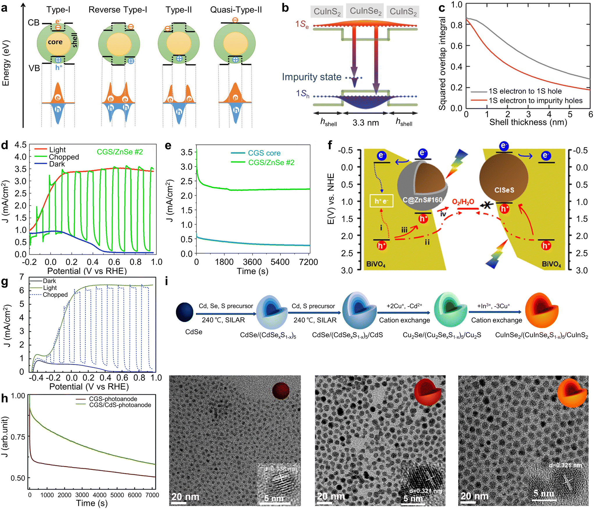 | ||
| Fig. 6 Core/shell structures of Cu-based I–III–VI QDs for PEC hydrogen production. (a) Schematic illustration showing different types of core/shell QDs. Adapted with permission from ref. 16. Copyright 2021, Wiley. (b) Band structure and (c) shell layer thickness-dependent squared overlap integrals of the 1S electron state to the 1S hole state and the 1S electron to the impurity hole state of CISe/CIS core/shell QDs. Adapted with permission from ref. 58. Copyright 2018, Wiley. (d) J–V and (e) J–t curves of CGS QD-based PEC devices. Adapted with permission from ref. 59. Copyright 2022, Wiley. (f) Schematic diagram of the CISeS QDs/BiVO4 PEC water-splitting system. Adapted with permission from ref. 60. Copyright 2021, American Chemical Society. (g) J–V curves and (h) photocurrent density decay as a function of time of the CGS/CdS core/shell QD-sensitized photoanodes. Adapted with permission from ref. 61. Copyright 2019, Royal Society of Chemistry. (i) Schematic illustration for the synthesis of CISe/CISeS/CIS multi-shell QDs, and TEM images of CISe, CISe/CIS, and CISe/CISeS/CIS QDs. Adapted with permission from ref. 62. Copyright 2021, Elsevier. | ||
These core/shell structures permit facile modification of the optical properties of I–III–VI QDs through appropriate selection of shell materials. For example, Tong et al. reported the development of giant CISe/CIS core/shell QDs with quasi-Type-II band alignment using sequential cation exchange reactions, which was starting from CdSe/CdS QDs (Fig. 6b).58 They found, through theoretical simulations, that the squared overlap integral of the electron and hole wave functions depends on the thickness of the shell layer (Fig. 6c), allowing for controlled band alignment. As the shell layer thickness increases, the squared overlap integral diminishes, indicating that the lifetime is expected to extend correspondingly. This aligned qualitatively with the observed experimental results. The resulting photoanodes, employing QDs with a 6-layer CIS shell, exhibited a photocurrent density of 3.1 mA cm−2, which is attributed to the quasi-Type-II band alignment.
PEC hydrogen production using core/shell QDs can be further improved by finely tuning the shell thickness. You et al. optimized the shell thickness of CuGaS2 (CGS)/ZnSe QDs, achieving a notable photocurrent density of 3.5 mA cm−2 in PEC devices (Fig. 6d).59 This represents a dramatic increase compared to the bare CGS QDs without shell (0.6 mA cm−2), resulting from the synergistic effects of passivating CGS core-related surface traps and suppressing non-radiative recombination. The core–shell structure was also proven effective in enhancing long-term stability. Devices utilizing optimally layered ZnSe QDs also maintained 62% of their original photocurrent density after 2 hours of illumination (Fig. 6e). In contrast, devices with bare QDs maintained only 40% of their original value.
Various combinations of core and shell materials have been reported for PEC hydrogen production using Cu based I–III–VI core/shell QDs. Cai et al. reported CISeS/ZnS QD-sensitized BiVO4 photoanodes for PEC hydrogen generation (Fig. 6f).60 Both the core CISeS and the core/shell CISeS/ZnS QDs exhibited a similar tetrahedral shape with a chalcopyrite phase. The ZnS layer thickness is less than 1 nm. Despite its ultrathin thickness, the ZnS shell effectively suppressed non-radiative recombination, thereby improving the PEC performance with a photocurrent density value of 3.17 mA cm−2. This value is 1.7 times higher than that of the core CISeS QD-based device. The improvement was attributed to an additional hole migration pathway in the core/shell CISeS/ZnS QDs: direct charge migration from the QDs into the electrolyte due to their favorable band alignment. Conversely, this pathway can be suppressed in core CISeS QDs because of mismatched band alignment.
Channa et al. attained a high photocurrent density of 6.5 mA cm−2 using CGS/CdS core/shell QDs.61 The average diameter of CGS QDs, as observed in TEM images, increased from 4 nm for the CGS core to 6 nm for the CGS/CdS core/shell QDs, implying three monolayers of the CdS shell. Estimated optical bandgaps from absorption spectra were 2.7 eV for the CGS core and 2.5 eV for CGS/CdS core/shell QDs. The narrowed bandgap of CGS/CdS core/shell QDs is advantageous for augmenting solar absorption. Consequently, compared to the photoanodes based on bare CGS QDs, the photoanodes utilizing CGS/CdS core/shell QDs demonstrated a significant increase (about eightfold) in a saturated photocurrent density, reaching around 6.5 mA cm−2 (Fig. 6g). The photocurrent density of photoanodes using CGS/CdS core/shell QDs maintained about 60% of their original value after two hours of illumination, whereas those using CGS core QDs retained around 50% (Fig. 6h). To evaluate stability under ambient conditions, both purified core and core/shell QD samples were left exposed to the open air for 72 hours. Following this period, the core QDs showed signs of degradation, as indicated by a change in color, while the core/shell QDs exhibited no noticeable change. The photoanode with the degraded CGS core QDs demonstrated a photocurrent density of about 0.3 mA cm−2, nearly identical to that of the bare TiO2-based photoanode. Conversely, the CGS/CdS core/shell QD-based photoanode sustained nearly the same photocurrent density for three months, indicating enhanced stability compared to the CGS core QDs under environmental conditions. Despite its superior PEC performance, the shell layers of the QDs contained toxic Cd elements.
It is critical to balance the shell thickness; excessive shell layers can induce the lattice strain, deteriorating the optical and electrochemical properties of the QDs.79–82 To overcome this challenge, recent studies have introduced gradient multi-shell structures (Fig. 6i).62 Gradient multi-shell QDs of CISe/CISeS/CIS were synthesized using a sequential cation exchange method from CdSe/CdSeS/CdS QDs, preserving the morphology of the original QDs. This gradient multi-shell structure effectively mitigates lattice mismatch between the zinc blende core (d-spacing of 0.338 nm) and the wurtzite shell (d-spacing of 0.321 nm), and also enhances charge transfer between the QDs and interfacial layers. As a result, a photocurrent density value of 4.5 mA cm−2 was achieved, representing a 70% improvement over the single core/shell structure. Moreover, the PEC device utilizing QDs with a gradient multi-shell structure demonstrated greater stability than devices employing QDs with either a single-shell structure or a core-only structure. Specifically, photoanodes based on CISe, CISe/CIS, and CISe/CISeS/CIS QDs retained 53%, 74%, and 83% of their initial photocurrent density after two hours of illumination, respectively. This suggests that core/shell/shell structures offer superior stability compared to core and core/shell structures.
The core–shell structure offers another advantage: easy interface engineering by controlling the thickness of the shell layers. Wang et al. examined how shell thickness affects the properties of CIS/CdS QDs.63 They investigated the band structures and dynamics of photoexcited charges using femtosecond transient absorption pump–probe spectra (Fig. 7a and b). By comparing the CIS core to the CIS/CdS core/shell structure QDs, it was observed that the recombination process was prolonged to hundreds of picoseconds after applying a CdS shell to the CIS core. With a thicker CdS shell, an ultralong excited state was noted. This thicker shell was shown to effectively passivate surface traps and suppress non-radiative recombination, crucially modulating the interface between the core and shell. Additionally, the formation of a quasi-type II band structure, favorable for charge separation, was achieved by increasing the shell thickness. As a result, a good photocurrent density of 6.0 mA cm−2 was achieved, along with improved photon-to-electron conversion efficiency in the 450 to 700 nm range (Fig. 7c). The photoanode based on CIS/CdS QDs with a thicker CdS shell also demonstrated notable stability, maintaining 78.9% of its initial photocurrent density after 2 hours of operation, a testament to the protective benefits of the thicker shell (Fig. 7d).
 | ||
| Fig. 7 Interface optimization in core/shell heterostructure QDs for PEC hydrogen production. Transient absorption spectra of (a) CIS and (b) CIS/CdS QDs. (c) IPCE spectra and (d) J–t measurement of CIS/CdS QDs as a function of shell thickness. Adapted with permission from ref. 63. Copyright 2020, American Chemical Society. TEM images of (e) CISeS core and (f–h) CISeS/CdSeS/CdS core/shell QDs with varying shell thickness. (i) Shell-thickness-dependent PL spectra of CISeS/CdSeS/CdS core/shell QDs. Adapted with permission from ref. 64. Copyright 2018, Wiley. | ||
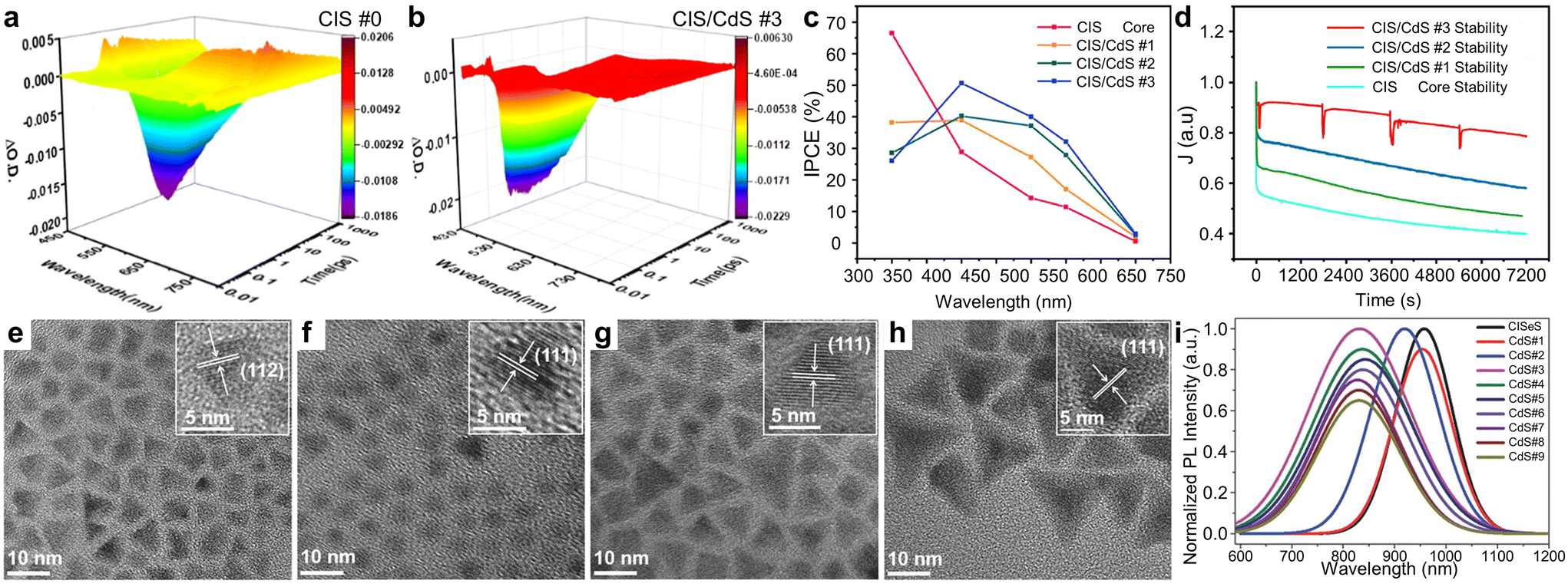
Meanwhile, Tong et al. synthesized pyramidal-shaped CISeS/CdSeS/CdS QDs and investigated interfacial modifications within the multi-shell structures.64 Initially, pyramidal-shaped CISeS QDs were synthesized and purified (Fig. 7e). Subsequently, Cd, Se, and S precursors were introduced to the reaction mixture to facilitate the growth of shell layers (Fig. 7f–h). The thicknesses of the CdSeS and CdS layers were finely tuned by adjusting the volume of introduced precursors. For QDs with medium-sized shell layers, the PL spectra gradually red-shifted with increased layer thickness, suggesting electron delocalization due to the added CdSeS layers (Fig. 7i). When outer CdS layers were added, the PL peak positions displayed a slight blue shift, attributed to the passivation from the wider bandgap CdS. The extended PL lifetime observed in CISeS/CdSeS/CdS QDs, compared to core CISeS QDs, indicated reduced spatial electron–hole overlap and suppressed surface charge carrier recombination, which are advantageous for PEC applications. The PEC system employing CISeS/CdSeS/CdS QDs with optimized shell thickness achieved a photocurrent density of 5.5 mA cm−2, surpassing that of counterparts with excessively thick shell layers. The PEC performances of Cu-based QD-sensitized photoanodes are summarized in Table 1.50–64,83–88
| QDs | Photoanode structure | Photocurrent density | Remark | Ref. |
|---|---|---|---|---|
| CIS | TiO2/QDs | 1.92 mA cm−2 | 83 | |
| CIS | TiO2/QDs/ZnS | 0.8 mA cm−2 | 84 | |
| CIS | TiO2/Au/QDs | 3.8 mA cm−2 | 85 | |
| CISe | TiO2/QDs/ZnS/SiO2 | 8.5 mA cm−2 | 86 | |
| CISe | TiO2/QDs/ZnS/SiO2 | 10.7 mA cm−2 | Defect engineering | 50 |
| CZIS | TiO2/QDs/ZnS | 4.4 mA cm−2 | Zn alloying | 51 |
| MnCIS/ZnS | TiO2/QDs/ZnS | 5.7 mA cm−2 | Mn alloying and ZnS shell | 52 |
| CISeS/ZnS | TIO2/QDs/ZnS | 5.3 mA cm−2 | Se, S alloying and ZnS shell | 55 |
| CISeS/ZnS | BiVO4/QDs/NiFeOx | 3.17 mA cm−2 | Se, S alloying and ZnS shell | 60 |
| CuInTexSe2−x/CdS | TIO2/QDs/ZnS | 4.5 mA cm−2 | Te, Se alloying and CdS shell | 88 |
| Mn:CISe/ZnSe | TIO2/QDs/ZnS | 6.0 mA cm−2 | Mn doping and ZnSe shell | 53 |
| Cu:ZnInSe | TIO2/QDs/ZnS | 11.23 mA cm−2 | Cu doping | 54 |
| Zn:CIS | TIO2/MoS2/reduced GO/QDs/ZnS | 0.44 mA cm−2 | Zn doping | 87 |
| CISe | TIO2/QDs/ZnS | 8.2 mA cm−2 | Ligand modification | 56 |
| Zn:CIS | BiVO4/QDs | 3.8 mA cm−2 | Zn doping and ligand modification | 57 |
| CISe/CIS | TIO2/QDs/ZnS | 3.1 mA cm−2 | CIS shell | 58 |
| CGS/ZnSe | TIO2/QDs/ZnS | 3.5 mA cm−2 | ZnSe shell | 59 |
| CGS/CdS | TIO2/QDs/ZnS | 6.5 mA cm−2 | CdS shell | 61 |
| CISe/CISeS/CIS | TIO2/QDs/ZnS | 4.5 mA cm−2 | Multi shell | 62 |
| CISeS/CdSeS/CdS | TIO2/QDs/ZnS | 5.5 mA cm−2 | Multi shell | 64 |
| CIS/CdS | TIO2/QDs/ZnS | 6.0 mA cm−2 | CdS shell | 63 |
4. Silver-based I–III–VI quantum dots
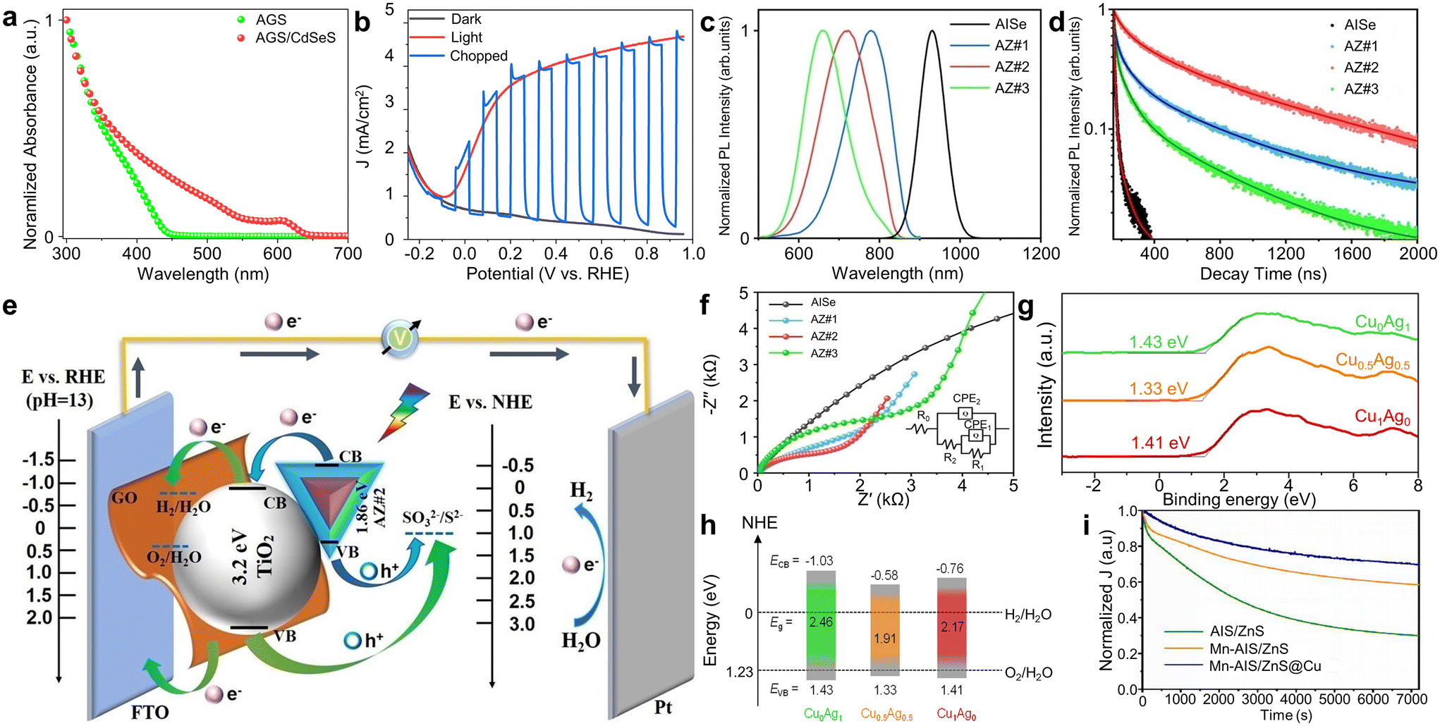
Ag-based I–III–VI QDs are another prominent category of I–III–VI QDs for PEC applications because of their non-toxic nature and excellent optical and electrical properties. In particular, they exhibit bandgap positions similar to those of Cu-based counterparts (Fig. 2c–e). Although they share similar optical properties, Ag-based I–III–VI materials exhibit several distinct aspects from their Cu-based counterparts. Firstly, Ag-based I–III–VI materials generally display superior electrical properties compared to Cu-based ones. For example, they show higher carrier concentrations (8 × 1015 cm−3 for AgInSe2vs. 5 × 1015 cm−3 for CuInSe2) and mobilities (25 cm2 V−1 s−1 for AgInSe2 compared to 6 cm2 V−1 s−1 for CuInSe2).89 However, it is important to note that silver is a rarer metal with higher production costs and less abundance on Earth. Another point of difference lies in ionic charge: Cu ions can have a charge of either 1+ or 2+, whereas Ag ions are consistently 1+. This means Cu-based QDs can contain both Cu1+ and Cu2+ within a single particle, offering the potential to fine-tune the functional properties of Cu-based QDs at an atomic level through the adjustment of the Cu1+/Cu2+ ratio.90,91 On the other hand, the potential for fine-tuning the functional properties of Ag-based QDs has been less explored.AgGaS2 (AGS) QDs hold the potential for excellent absorption characteristics for PEC hydrogen generation. Li et al. successfully synthesized AGS/CdSeS QDs and utilized them to develop both photodetectors and PEC photoanodes, demonstrating their capabilities in light detection and solar energy conversion.92 They employed a two-step synthesis method for AGS/CdSeS QDs, starting with the purification of the synthesized AGS core followed by the growth of CdSeS shell layers. The addition of these shell layers significantly enhanced light absorption up to 650 nm (Fig. 8a). Tauc plots indicated that these QDs possess type II band alignments, which are conducive to effective charge carrier separation and transfer. Consequently, AGS/CdSeS QD-sensitized TiO2 photoanodes achieved a photocurrent density of 4.8 mA cm−2, attributable to robust light absorption and enhanced charge carrier dynamics (Fig. 8b).
 | ||
| Fig. 8 Ag-based QDs for PEC hydrogen production. (a) Absorption spectra of AGS and AGS/CdSeS QDs. (b) J–V curves of AGS/CdSeS QD-based photoanodes. Adapted with permission from ref. 92. Copyright 2022, Elsevier. (c) PL and (d) time-resolved PL spectra of AISe/ZnSe QDs. (e) Band alignment and (f) EIS Nyquist plots of AISe/ZnSe QD-sensitized TiO2 photoanodes. Adapted with permission from ref. 93. Copyright 2021, Wiley. (g) Valence band XPS spectra and (h) the corresponding energy band diagram for Cu-doped AIS QDs. Adapted with permission from ref. 94. Copyright 2022, American Chemical Society. (i) Time-dependent changes in photocurrent for the MnAIS/Cu:ZnS QD-sensitized TiO2 photoelectrodes and their controlled counterparts. Adapted with permission from ref. 95. Copyright 2022, Elsevier. | ||
AgInSe2 (AISe) QDs exhibit broad light absorption ranges due to their narrow bandgap of 1.24 eV in bulk form and are extensively studied for PEC applications. However, the significant surface traps and defects in AISe QDs degrade their photostability and electrical properties. Thus, various methods have been applied for these Ag-based QDs for improving their PEC hydrogen production, which are similar to those applied for Cu-based QDs. Long et al. successfully grew ZnSe shell layers onto the AISe core and modified the optical and electrical properties of AISe/ZnSe core/shell QDs by adjusting the shell thickness (Fig. 8c).93 This adjustment enabled broad control over the PL emission center from approximately 800 nm to 600 nm. Additionally, the band structure of AISe/ZnSe core/shell QDs proved advantageous for charge extraction from the AISe core to the ZnSe shell. Time-resolved PL measurements indicated that a sample with excessively thick shell layers, labeled AZ#3 in Fig. 8d, exhibited the enhanced exciton recombination due to unfavorable band alignment. Whereas, an optimal shell thickness led to desirable Type II band alignment, reducing charge transfer resistance (Fig. 8e). This is corroborated by the smaller semicircle radius observed in EIS Nyquist plots for AISe/ZnSe QD-sensitized TiO2 photoanodes with optimized shell thickness (Fig. 8f). Finally, this enhanced the efficiency of QD-based solar hydrogen generation, showing the photocurrent density of 7.5 mA cm−2.
Doping of Ag-based I–III–VI QDs also provides effective ways of modulating their optical and electrical properties. Guo et al. successfully demonstrated band structure engineering in AgInS2 (AIS)/ZnS core/shell QDs through Cu ion doping and defect passivation.94 They measured the valence band positions of AIS QDs with varying Cu ion concentrations through the secondary electron cutoff in the valence band XPS spectra (Fig. 8g). Compared to undoped AIS QDs, both conduction and valence bands of these Cu-doped QDs were found to exhibit a downward shift (Fig. 8h). This resulted in a narrowed bandgap of Cu-doped AIS QDs, leading to enhanced visible-light absorption. Density functional theory (DFT) calculations was also employed to confirm the experimental results. The resulting TiO2 photoanodes sensitized with Cu-doped AIS/ZnS QDs demonstrated a remarkable photocurrent density of 5.8 mA cm−2.
Xia et al. modulated both the core and shell components of AIS/ZnS QDs by alloying the core with Mn and introducing Cu dopants into the shell.95 The incorporation of Mn into AIS/ZnS core/shell QDs increased the bandgap of the core part, resulting in a reduced band offset between the conduction band of the MnAIS core and that of the ZnS shell. This modification enhanced the charge separation, verified by the extended carrier lifetime. Additionally, the subsequent introduction of Cu dopants in the shell material created Cu+ states that can effectively capture photogenerated holes from the core material. This led to reduced charge recombination within these QDs and improved charge transfer dynamics for PEC hydrogen production. By finely tuning the levels of Mn alloying and Cu doping, the photoanodes using MnAIS/Cu:ZnS QDs achieved a high photocurrent density of 6.4 mA cm−2 under standard solar illumination (AM 1.5 G, 100 mW cm−2). Furthermore, these PEC devices demonstrated exceptional durability, retaining about 70% of its initial photocurrent density after two hours of continuous light exposure (Fig. 8i). Their findings highlight the potential of strategically modifying the core and shell materials in core/shell QDs as a promising approach to develop highly efficient and durable QD-based solar energy conversion devices.
Additional protective layer can further enhance the PEC performance of Ag-based I–III–VI QDs. Guo et al. reported high performance PEC hydrogen production using Cu-doped AgIn5S8 (CAIS)/ZnS core/shell QDs.96 In this study, the average diameter of the CAIS core was approximately 2.9 nm, while that of the CAIS/ZnS core/shell QDs with optimized shell thickness was ∼4.5 nm. This optimization resulted in a photocurrent density of 7.55 mA cm−2. Additional ZnS protective layers was introduced onto CAIS/ZnS QD-sensitized photoanodes, resulting in the further increase in photocurrent density up to 14.60 mA cm−2 (Fig. 9a). The dramatic enhancement can be ascribed to additional passivation of trap states in QDs, as evidenced by the prolonged PL decay time (Fig. 9b).
 | ||
| Fig. 9 Interfacial engineering between QDs and photoanode materials. (a) J–V curves of CAIS/ZnS QD-based photoanodes. (b) Time-resolved PL spectra of CAIS/ZnS QD-based TiO2 photoanodes with and without ZnS protective layers. Adapted with permission from ref. 96. Copyright 2020, Royal Society of Chemistry. (c) J–V curves and (d) hydrogen production of ZnS/AIS-QD-based photoanodes. Adapted with permission from ref. 97. Copyright 2020, Elsevier. (e) Absorption spectra of TiO2–GO with varying GO concentrations. (f) Mott–Schottky plots for bare TiO2, ZAISe QD-sensitized TiO2, and ZAISe QD-sensitized TiO2–GO photoanodes. (g) Schematic illustration describing the transport mechanism of photoexcited electrons in ZAISe QD-sensitized TiO2–GO photoanodes. (h) EIS Nyquist plots for ZAISe QD-sensitized TiO2–GO photoanodes. Adapted with permission from ref. 98. Copyright 2021, Elsevier. | ||
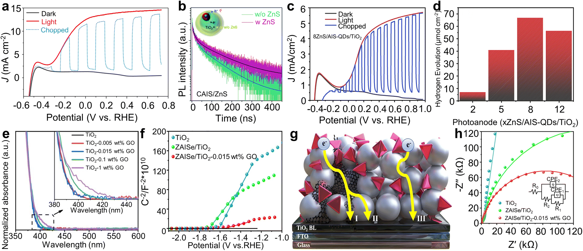
The passivation layer thickness is important for the performance and stability of PEC photoanodes based on Ag-based I–III–VI QDs. Tong et al. investigated the impact of the thickness of ZnS passivation layers on PEC characteristics of AIS QD sensitized-photoanodes.97 Photoanodes with 8 ZnS layers exhibited the shortest PL lifetime, suggesting reduced non-radiative recombination at QD surface defects and at QD/electrolyte interfaces, facilitating effective electron transfer from QDs to TiO2. Owing to these synergistic effects, PEC devices with 8 ZnS layers achieved the highest photocurrent density of approximately 5.7 mA cm−2 (Fig. 9c), along with a hydrogen evolution rate of approximately 67 μmol cm−2 (Fig. 9d). The photoanodes also maintained a faradaic efficiency of ∼61% during two hours of device operation time, indicating good stability of the ZnS passivation layers. For practical applications, they increased the number of ZnS passivation layers to 12 and conducted a prolonged 4 h operational stability test. The photoanodes maintained a stable photocurrent density of 2 mA cm−2, which is 58% of the initial value, demonstrating further reduced photocorrosion.
Another notable instance of interface engineering involves constructing a hybrid composite with graphene oxide (GO). Long et al. developed ZnAgInSe (ZAISe) QD-based photoanodes using TiO2–GO hybrid composites.98 They regulated the GO concentration, because the transparency of the film could be decreased due to scattering effect of GO (Fig. 9e). This reduction could lead to less solar radiation reaching the QDs, crucial for photoexciton generation, and thus might decrease the PEC performances. Hence, a GO concentration of 0.015 wt% was selected. The Mott–Schottky analysis revealed that the ZAISe QD-sensitized TiO2–GO photoanodes had higher carrier density, compared to pure TiO2 and TiO2/ZAISe QDs photoanodes (Fig. 9f). Their proposed mechanism to explain the enhanced properties is as follows. Incorporating GO nanosheets into the photoanodes allowed photogenerated electrons from QDs to be transported to fluorine-doped tin oxide (FTO) electrodes via either the TiO2 to GO route or directly through GO to TiO2 (Fig. 9g). Conversely, in the absence of GO, electrons traverse through the grain boundaries of TiO2 to reach the FTO glass, resulting in higher electron transport resistance. The EIS Nyquist plot analysis supported the suggested mechanism (Fig. 9h). Consequently, a higher photocurrent density of 6.7 mA cm−2 was achieved for ZAISe QD-based photoanodes with GO, marking a 24% increase compared to those without GO. The PEC performances of Ag-based QD-sensitized photoanodes are summarized in Table 2.92–103
| QDs | Photoanode structure | Photocurrent density | Remark | Ref. |
|---|---|---|---|---|
| AgIn5S8 | Ti/TiO2/QDs | 125 μA cm−2 | 101 | |
| AIS | Graphene/QDs | 145 μA cm−2 | 102 | |
| AIS | TIO2/QDs/ZnS | 5.7 mA cm−2 | 97 | |
| AISe/ZnSe | TIO2–GO/QDs/ZnS | 7.5 mA cm−2 | ZnSe shell | 93 |
| AISe/AISeS/AIS | TIO2/QDs/ZnS | ∼1.14 mA cm−2 | Multi shell | 100 |
| AgGaS2/CdSeS | TIO2/QDs/ZnS | 4.8 mA cm−2 | CdSeS shell | 92 |
| Cu:AIS/ZnS | TIO2/QDs/ZnS | 5.8 mA cm−2 | Cu alloying and ZnS shell | 94 |
| MnAIS/Cu:ZnS | TIO2/QDs/ZnS | 6.4 mA cm−2 | Mn alloying and Cu doped shell | 95 |
| ZAISe | TIO2–GO/QDs/ZnS | 6.7 mA cm−2 | Zn alloying | 98 |
| Cu:AgIn5S8/ZnS | TIO2/QDs/ZnS | 14.6 mA cm−2 | Cu doping and ZnS shell | 96 |
| Cu:AgIn5S8 | TIO2/QDs/ZnS | 9.8 mA cm−2 | Cu doping | 99 |
| Cu:AISe/Cu:ZnSe | TIO2/QDs/ZnS | 9.1 mA cm−2 | Cu doped core and Cu doped shell | 103 |
5. Conclusion and outlook
In conclusion, this review has summarized the recent advances and progress of I–III–VI QDs for the applications of PEC hydrogen generation. Techniques such as interfacial engineering through ligand functionalization as well as structural engineering, including doping or alloying with other elements, have proven effective in enhancing the efficiency and stability of PEC devices using I–III–VI QDs. Additionally, the development of core/shell structures has provided robustness and further control over optical properties, enabling these devices to achieve photocurrent densities comparable to those of heavy-metal-based PEC photoanodes. Interfacial engineering between QDs and photoanode materials has also been examined, which is highly related to charge carrier transporting ability and photostability.To sum up, defect engineering in QDs allows for the manipulation of properties such as carrier concentration and trap densities, leading to improved carrier separation and transport. As a result, enhanced PEC performance can be achieved without altering the morphologies and optical characteristics of QDs. Meanwhile, a key benefit of alloying with other elements is the adjustment of bandgap alignment. Alloyed QDs with an optimized ratio can absorb a wider range of wavelengths compared to non-alloyed variants, thus boosting carrier generation. Doping, which is distinct from alloying, introduces dopant-associated band states; when these states are positioned between the conduction bands of the core and shell, they facilitate efficient charge carrier separation through electron delocalization, enhancing PEC performance. Ligand modification techniques typically alter charge transfer or injection dynamics by creating favorable heterojunctions with metal electrodes. Core/shell heterostructures not only provide robustness to QDs but also enhance charge separation through a type II structure.
However, several limitations and challenges remain that must be addressed to realize the practical applications.
(i) Poor long-term stability and durability: I–III–VI QDs typically exhibit a higher density of trap states due to their non-stoichiometry, making them less resistant to moisture, oxidation, and photocorrosion compared to heavy-metal QDs. Consequently, hydrogen evolution tests in reported studies have been limited to a few hours. Fundamental understanding on the degradation mechanism of QDs may offer viable solutions.104–106
(ii) Use of sacrificial agents: Commonly, PEC systems employ sacrificial agents like Na2S/Na2SO3 to enhance device stability, which increases production costs and adds complexity. These agents consume photogenerated holes from QDs and can be rapidly degenerated. Therefore, strategies focusing on using neutral electrolytes such as Na2SO4 and reducing production costs are highly sought after.
(iii) Relatively lower photocurrent density compared to heavy-metal containing QD-based PECs: Despite advancements in synthesis protocols for I–III–VI QDs, their PEC photocurrent densities still lag behind those of conventional QDs containing heavy-metals (e.g., above 20 mA cm−2 for PbS39 and CdSe QDs40). High photocurrent densities are typically achieved through complex methods such as core/shell heterostructures, alloying, or doping. Future research might concentrate on optimizing and simplifying synthesis routes for pure I–III–VI QDs to achieve superior photocurrent densities.
(iv) Controlling and understanding properties at the atomic scale: The optical and electrochemical properties of I–III–VI QDs are intricately tied to their atomic-level structure. Factors such as the Cu/In ratio, synthesis pathways, defect state positioning, and choice of reaction precursors significantly influence these properties, even when QDs appear similar at the nanometer scale.107 Unravelling these fundamental relationships is key to enhancing PEC performance.
(v) Avoiding hazardous and toxic reaction precursors: While the final I–III–VI QDs are non-toxic, their synthesis often involves dangerous organic precursors (e.g., 1-dodecanethiol for sulfur source) and high temperatures, which contradicts their eco-friendly nature. Innovative synthesis techniques that utilize safer materials are crucial to achieving green production processes for I–III–VI QDs.
(vi) Developing a straightforward, low-cost fabrication process for I–III–VI QDs: Most research on I–III–VI QD-based PEC systems have depended on complex and time-consuming procedures to achieve high performance. Techniques such as doping/alloying, post-synthesis treatment, and the growth of single or multi-shell layers contribute to this complexity and escalate production costs. Especially, the price of precursor materials for Ag-based QDs is expensive. Optimizing synthesis routes through iterative trials and a thorough investigation of underlying mechanisms may serve as an effective guide.108–110
Finally, future design strategies might consider the following approaches. The initial step should focus on improving the stability and performance of pure QDs without the introduction of other elements. Insights from the deformation mechanisms of QDs can guide strategies to enhance stability. Similarly, efforts to control and understand the fundamental properties of I–III–VI QDs present opportunities to boost performance. Subsequently, fine optimization should be performed, encompassing control over core size and shape, shell thickness and composition, as well as alloy/doping concentrations.
Author contributions
The manuscript was written through contributions of all authors. All authors have given approval to the final version of the manuscript.Conflicts of interest
There are no conflicts to declare.Acknowledgements
This work was supported by the National Research Foundation of Korea (NRF) grant funded by the Korean government (MSIT) (grant no. 2021R1C1C1007844).References
- I. Y. Kim, S. Kim, S. Premkumar, J.-H. Yang, S. Umapathy and A. Vinu, Small, 2020, 16, 1903572 CrossRef CAS PubMed
.
- S. B. Barim, G. Raptapoulos, S. Rommel, M. Aindow, P. Paraskevopoulou and C. Erkey, Electrochim. Acta, 2022, 434, 141251 CrossRef CAS
- S. B. Barim, E. Uzunlar, S. E. Bozbag and C. Erkey, J. Electrochem. Soc., 2020, 167, 054510 CrossRef CAS
- F. Liu and Z. Fan, Chem. Soc. Rev., 2023, 52, 1723–1772 RSC
- Y. Ma, J. Yu, M. Sun, B. Chen, X. Zhou, C. Ye, Z. Guan, W. Guo, G. Wang, S. Lu, D. Xia, Y. Wang, Z. He, L. Zheng, Q. Yun, L. Wang, J. Zhou, P. Lu, J. Yin, Y. Zhao, Z. Luo, L. Zhai, L. Liao, Z. Zhu, R. Ye, Y. Chen, Y. Lu, S. Xi, B. Huang, C.-S. Lee and Z. Fan, Adv. Mater., 2022, 34, 2110607 CrossRef CAS PubMed
- A. Fujishima and K. Honda, Nature, 1972, 238, 37–38 CrossRef CAS PubMed
- M. V. Pavliuk, S. Wrede, A. Liu, A. Brnovic, S. Wang, M. Axelsson and H. Tian, Chem. Soc. Rev., 2022, 51, 6909–6935 RSC
- Y. Lim, S. Y. Lee, D. Kim, M.-K. Han, H. S. Han, S. H. Kang, J. K. Kim, U. Sim and Y. I. Park, Chem. Eng. J., 2022, 438, 135503 CrossRef CAS
- S. An, Z. Wu, H. Jeong, J. Lee, S. Y. Jeong, W. Lee, S. Kim, J. W. Han, J. Lim, H. Cha, H. Y. Woo and D. S. Chung, Small, 2023, 19, 2204905 CrossRef CAS PubMed
- S. Liang, S. He, M. Zhang, Y. Yan, T. Jin, T. Lian and Z. Lin, J. Am. Chem. Soc., 2022, 144, 12901–12914 CrossRef CAS PubMed
- H. Noh, J. Lee, H. Ma, J. Shin, I. Roh, J. Yang and T. Yu, J. Ind. Eng. Chem., 2023, 125, 277–283 CrossRef CAS
- L. Wang, Y. Chen, Y. Lai, X. Zhao, K. Zheng, R. Wang and Y. Zhou, Nanoscale, 2024, 16, 188–194 RSC
- S. H. Noh, K. H. Lee, H. S. Yang, J. Jung, E. H. Suh, J. G. Oh, S. C. Park and J. Jang, Chem. Eng. J., 2024, 481, 148127 CrossRef CAS
- H. Kim, J. W. Seo, W. Chung, G. M. Narejo, S. W. Koo, J. S. Han, J. Yang, J.-Y. Kim and S.-I. In, ChemSusChem, 2023, 16, e202202017 CrossRef CAS PubMed
- H. Kim, A. Choe, S. B. Ha, G. M. Narejo, S. W. Koo, J. S. Han, W. Chung, J.-Y. Kim, J. Yang and S.-I. In, ChemSusChem, 2023, 16, e202201925 CrossRef CAS PubMed
- L. Jin, H. Zhao, Z. M. Wang and F. Rosei, Adv. Energy Mater., 2021, 11, 2003233 CrossRef CAS
- H. Su, W. Wang, R. Shi, H. Tang, L. Sun, L. Wang, Q. Liu and T. Zhang, Carbon Energy, 2023, 5, e280 CrossRef CAS
- J. Li, H. Yuan, W. Zhang, B. Jin, Q. Feng, J. Huang and Z. Jiao, Carbon Energy, 2022, 4, 294–331 CrossRef CAS
- Z. Li, A. I. Channa, Z. M. Wang and X. Tong, Small, 2023, 19, 2305146 CrossRef CAS PubMed
- R. Zhao, Y. Zhang, F. Wu, J. Wang, F. Chen and W. Zhai, Nanoscale, 2024, 16, 3024–3033 RSC
- P. Dai, J. Xie, M. T. Mayer, X. Yang, J. Zhan and D. Wang, Angew. Chem., 2013, 125, 11325–11329 CrossRef
- L. Ji, M. D. McDaniel, S. Wang, A. B. Posadas, X. Li, H. Huang, J. C. Lee, A. A. Demkov, A. J. Bard, J. G. Ekerdt and E. T. Yu, Nat. Nanotechnol., 2015, 10, 84–90 CrossRef CAS PubMed
- C. Cao, X. Xie, Y. Zeng, S. Shi, G. Wang, L. Yang, C.-Z. Wang and S. Lin, Nano Energy, 2019, 61, 550–558 CrossRef CAS
- S. Hu, M. R. Shaner, J. A. Beardslee, M. Lichterman, B. S. Brunschwig and N. S. Lewis, Science, 2014, 344, 1005–1009 CrossRef CAS PubMed
- S. Ho-Kimura and W. Luo, Sustainable Energy Fuels, 2021, 5, 3102–3114 RSC
- C. B. Murray, D. J. Norris and M. G. Bawendi, J. Am. Chem. Soc., 1993, 115, 8706–8715 CrossRef CAS
- J. Lee, J. Yang, S. G. Kwon and T. Hyeon, Nat. Rev. Mater., 2016, 1, 16034 CrossRef CAS
- Z. Pan, H. Rao, I. Mora-Seró, J. Bisquert and X. Zhong, Chem. Soc. Rev., 2018, 47, 7659–7702 RSC
- J. Yang, M. K. Choi, U. J. Yang, S. Y. Kim, Y. S. Kim, J. H. Kim, D.-H. Kim and T. Hyeon, Nano Lett., 2021, 21, 26–33 CrossRef CAS PubMed
- H. A. Nguyen, G. Dixon, F. Y. Dou, S. Gallagher, S. Gibbs, D. M. Ladd, E. Marino, J. C. Ondry, J. P. Shanahan, E. S. Vasileiadou, S. Barlow, D. R. Gamelin, D. S. Ginger, D. M. Jonas, M. G. Kanatzidis, S. R. Marder, D. Morton, C. B. Murray, J. S. Owen, D. V. Talapin, M. F. Toney and B. M. Cossairt, Chem. Rev., 2023, 123, 7890–7952 CrossRef CAS PubMed
- J. S. Son, K. Park, S. G. Kwon, J. Yang, M. K. Choi, J. Kim, J. H. Yu, J. Joo and T. Hyeon, Small, 2012, 8, 2394–2402 CrossRef CAS PubMed
- H. C. Lee, M. S. Bootharaju, K. Lee, H. Chang, S. Y. Kim, E. Ahn, S. Li, B. H. Kim, H. Ahn, T. Hyeon and J. Yang, Adv. Sci., 2024, 11, 2307600 CrossRef CAS PubMed
- C. R. Kagan, E. Lifshitz, E. H. Sargent and D. V. Talapin, Science, 2016, 353, aac5523 CrossRef PubMed
- J. Yang, F. Muckel, B. K. Choi, S. Lorenz, I. Y. Kim, J. Ackermann, H. Chang, T. Czerney, V. S. Kale, S.-J. Hwang, G. Bacher and T. Hyeon, Nano Lett., 2018, 18, 7350–7357 CrossRef CAS PubMed
- F. Muckel, S. Lorenz, J. Yang, T. A. Nugraha, E. Scalise, T. Hyeon, S. Wippermann and G. Bacher, Nat. Commun., 2020, 11, 4127 CrossRef CAS PubMed
- K. Lee, Y. Kim, E. Ahn, J. I. Kwon, H. Ma, J. H. Jang, S. Li, H. C. Lee, G. Heon Lee, S. Lee, K. Kim, N. J. Sung, D. Kim, M. H. Song, M. K. Choi and J. Yang, Mater. Today, 2024 DOI:10.1016/j.mattod.2024.03.008
- D. C. Kim, H. Seung, J. Yoo, J. Kim, H. H. Song, J. S. Kim, Y. Kim, K. Lee, C. Choi, D. Jung, C. Park, H. Heo, J. Yang, T. Hyeon, M. K. Choi and D.-H. Kim, Nat. Electron., 2024 DOI:10.1038/s41928-024-01152-w
- J. Yang, M. K. Choi, D.-H. Kim and T. Hyeon, Adv. Mater., 2016, 28, 1176–1207 CrossRef CAS PubMed
- J.-Y. Kim, Y. J. Jang, J. Park, J. Kim, J. S. Kang, D. Y. Chung, Y.-E. Sung, C. Lee, J. S. Lee and M. J. Ko, Appl. Catal., B, 2018, 227, 409–417 CrossRef CAS
- K. Wang, C. Wang, Y. Tao, Z. Tang, D. Benetti, F. Vidal, Y. Liu, M. H. Rummeli, H. Zhao, F. Rosei and X. Sun, Adv. Funct. Mater., 2024, 2400580 CrossRef
- J. Yang, J.-Y. Kim, J. H. Yu, T.-Y. Ahn, H. Lee, T.-S. Choi, Y.-W. Kim, J. Joo, M. J. Ko and T. Hyeon, Phys. Chem. Chem. Phys., 2013, 15, 20517 RSC
- M. G. Panthani, C. J. Stolle, D. K. Reid, D. J. Rhee, T. B. Harvey, V. A. Akhavan, Y. Yu and B. A. Korgel, J. Phys. Chem. Lett., 2013, 4, 2030–2034 CrossRef CAS PubMed
- D. H. Jara, S. J. Yoon, K. G. Stamplecoskie and P. V. Kamat, Chem. Mater., 2014, 26, 7221–7228 CrossRef CAS
- S. Li, J. H. Jang, W. Chung, H. Seung, S. I. Park, H. Ma, W. J. Pyo, C. Choi, D. S. Chung, D.-H. Kim, M. K. Choi and J. Yang, ACS Nano, 2023, 17, 20013–20023 CrossRef CAS PubMed
- J.-Y. Kim, J. Yang, J. H. Yu, W. Baek, C.-H. Lee, H. J. Son, T. Hyeon and M. J. Ko, ACS Nano, 2015, 9, 11286–11295 CrossRef CAS PubMed
- C. Coughlan, M. Ibáñez, O. Dobrozhan, A. Singh, A. Cabot and K. M. Ryan, Chem. Rev., 2017, 117, 5865–6109 CrossRef CAS PubMed
- T. Torimoto, T. Kameyama, T. Uematsu and S. Kuwabata, J. Photochem. Photobiol., C, 2023, 54, 100569 CrossRef CAS
- S. Jain, S. Bharti, G. K. Bhullar and S. K. Tripathi, J. Lumin., 2020, 219, 116912 CrossRef CAS
- O. Yarema, M. Yarema and V. Wood, Chem. Mater., 2018, 30, 1446–1461 CrossRef CAS
- S. Li, S.-M. Jung, W. Chung, J.-W. Seo, H. Kim, S. I. Park, H. C. Lee, J. S. Han, S. B. Ha, I. Y. Kim, S.-I. In, J.-Y. Kim and J. Yang, Carbon Energy, 2023, 5, e384 CrossRef CAS
- C. Liu, X. Tong, A. I. Channa, X. Li, Z. Long, H. Feng, Y. You, R. Wang, F. Lin, C. F. Dee, A. Vomiero and Z. M. Wang, J. Mater. Chem. A, 2021, 9, 5825–5832 RSC
- R. Wang, X. Tong, A. I. Channa, Q. Zeng, J. Sun, C. Liu, X. Li, J. Xu, F. Lin, G. S. Selopal, F. Rosei, Y. Zhang, J. Wu, H. Zhao, A. Vomiero, X. Sun and Z. M. Wang, J. Mater. Chem. A, 2020, 8, 10736–10741 RSC
- R. Wang, X. Tong, Z. Long, A. I. Channa, H. Zhao, X. Li, M. Cai, Y. You, X. Sun and Z. Wang, Nano Res., 2022, 15, 7614–7621 CrossRef CAS
- B. Luo, J. Liu, H. Guo, X. Liu, R. Song, K. Shen, Z. M. Wang, D. Jing, G. S. Selopal and F. Rosei, Nano Energy, 2021, 88, 106220 CrossRef CAS
- X. Tong, Y. Zhou, L. Jin, K. Basu, R. Adhikari, G. S. Selopal, X. Tong, H. Zhao, S. Sun, A. Vomiero, Z. M. Wang and F. Rosei, Nano Energy, 2017, 31, 441–449 CrossRef CAS
- S. I. Park, S.-M. Jung, J.-Y. Kim and J. Yang, Materials, 2022, 15, 6010 CrossRef CAS PubMed
- M. Cai, X. Tong, H. Zhao, X. Li, Y. You, R. Wang, L. Xia, N. Zhou, L. Wang and Z. M. Wang, Small, 2022, 18, 2204495 CrossRef CAS PubMed
- X. Tong, X.-T. Kong, Y. Zhou, F. Navarro-Pardo, G. S. Selopal, S. Sun, A. O. Govorov, H. Zhao, Z. M. Wang and F. Rosei, Adv. Energy Mater., 2018, 8, 1701432 CrossRef
- Y. You, X. Tong, A. I. Channa, X. Li, C. Liu, H. Ye and Z. Wang, EcoMat, 2022, 4, e12206 CrossRef CAS
- M. Cai, X. Li, H. Zhao, C. Liu, Y. You, F. Lin, X. Tong and Z. M. Wang, ACS Appl. Mater. Interfaces, 2021, 13, 50046–50056 CrossRef CAS PubMed
- A. I. Channa, X. Tong, J.-Y. Xu, Y. Liu, C. Wang, M. N. Sial, P. Yu, H. Ji, X. Niu and Z. M. Wang, J. Mater. Chem. A, 2019, 7, 10225–10230 RSC
- F. Li, M. Zhang, D. Benetti, L. Shi, L. V. Besteiro, H. Zhang, J. Liu, G. S. Selopal, S. Sun, Z. Wang, Q. Wei and F. Rosei, Appl. Catal., B, 2021, 280, 119402 CrossRef CAS
- C. Wang, X. Tong, W. Wang, J.-Y. Xu, L. V. Besteiro, A. I. Channa, F. Lin, J. Wu, Q. Wang, A. O. Govorov, A. Vomiero and Z. M. Wang, ACS Appl. Mater. Interfaces, 2020, 12, 36277–36286 CrossRef CAS PubMed
- X. Tong, X.-T. Kong, C. Wang, Y. Zhou, F. Navarro-Pardo, D. Barba, D. Ma, S. Sun, A. O. Govorov, H. Zhao, Z. M. Wang and F. Rosei, Adv. Sci., 2018, 5, 1800656 CrossRef PubMed
- L. Yang, S. Zhang, B. Xu, J. Jiang, B. Cai, X. Lv, Y. Zou, Z. Fan, H. Yang and H. Zeng, Nano Lett., 2023, 23, 2443–2453 CrossRef CAS PubMed
- S. Shishodia, B. Chouchene, T. Gries and R. Schneider, Nanomaterials, 2023, 13, 2889 CrossRef CAS PubMed
- Z.-Q. Wei, S. Hou, S.-C. Zhu, Y. Xiao, G. Wu and F.-X. Xiao, Adv. Funct. Mater., 2022, 32, 2106338 CrossRef CAS
- Z.-Q. Wei, X.-C. Dai, S. Hou, Y.-B. Li, M.-H. Huang, T. Li, S. Xu and F.-X. Xiao, J. Mater. Chem. A, 2020, 8, 177–189 RSC
- S. Hou, X.-C. Dai, Y.-B. Li, M.-H. Huang, T. Li, Z.-Q. Wei, Y. He, G. Xiao and F.-X. Xiao, J. Mater. Chem. A, 2019, 7, 22487–22499 RSC
- G. Zhang, Z. Guan, J. Yang, Q. Li, Y. Zhou and Z. Zou, Sol. RRL, 2022, 6, 2200587 CrossRef CAS
- J. Du, R. Singh, I. Fedin, A. S. Fuhr and V. I. Klimov, Nat. Energy, 2020, 5, 409–417 CrossRef CAS
- Z. Pan, I. Mora-Seró, Q. Shen, H. Zhang, Y. Li, K. Zhao, J. Wang, X. Zhong and J. Bisquert, J. Am. Chem. Soc., 2014, 136, 9203–9210 CrossRef CAS PubMed
- A. Jiang, H. Guo, S. Yu, F. Zhang, T. Shuai, Y. Ke, P. Yang and Y. Zhou, Appl. Catal., B, 2023, 332, 122747 CrossRef CAS
- C. Xia, W. Wu, T. Yu, X. Xie, C. van Oversteeg, H. C. Gerritsen and C. de Mello Donega, ACS Nano, 2018, 12, 8350–8361 CrossRef CAS PubMed
- D. M. Gates, Science, 1966, 151, 523–529 CrossRef CAS PubMed
- B. O. Dabbousi, J. Rodriguez-Viejo, F. V. Mikulec, J. R. Heine, H. Mattoussi, R. Ober, K. F. Jensen and M. G. Bawendi, J. Phys. Chem. B, 1997, 101, 9463–9475 CrossRef CAS
- M. K. Choi, J. Yang, K. Kang, D. C. Kim, C. Choi, C. Park, S. J. Kim, S. I. Chae, T.-H. Kim, J. H. Kim, T. Hyeon and D.-H. Kim, Nat. Commun., 2015, 6, 7149 CrossRef CAS PubMed
- M. R. Shariati, A. Samadi-Maybodi and A. H. Colagar, J. Mater. Chem. A, 2018, 6, 20433–20443 RSC
- H. Zhao, M. Chaker and D. Ma, J. Mater. Chem., 2011, 21, 17483 RSC
- J. Lim, B. G. Jeong, M. Park, J. K. Kim, J. M. Pietryga, Y.-S. Park, V. I. Klimov, C. Lee, D. C. Lee and W. K. Bae, Adv. Mater., 2014, 26, 8034–8040 CrossRef CAS PubMed
- J. Kim, H. J. Shim, J. Yang, M. K. Choi, D. C. Kim, J. Kim, T. Hyeon and D.-H. Kim, Adv. Mater., 2017, 29, 1700217 CrossRef PubMed
- M. K. Choi, J. Yang, D. C. Kim, Z. Dai, J. Kim, H. Seung, V. S. Kale, S. J. Sung, C. R. Park, N. Lu, T. Hyeon and D.-H. Kim, Adv. Mater., 2018, 30, 1703279 CrossRef PubMed
- T.-L. Li and H. Teng, J. Mater. Chem., 2010, 20, 3656 RSC
- X. Tong and Z. M. Wang, IOP Conf. Ser. Earth Environ. Sci., 2018, 170, 042050 CrossRef
- W. Li, L. Yao, Z. Zhang, H. Geng, C. Li, Y. Yu, P. Sheng and S. Li, Mater. Sci. Semicond. Process., 2019, 99, 106–113 CrossRef CAS
- J. Kim, Y. J. Jang, W. Baek, A. R. Lee, J.-Y. Kim, T. Hyeon and J. S. Lee, ACS Appl. Mater. Interfaces, 2022, 14, 603–610 CrossRef CAS PubMed
- F. Li, D. Benetti, M. Zhang, L. Shi, J. Feng, Q. Wei and F. Rosei, ACS Appl. Mater. Interfaces, 2022, 14, 54790–54802 CrossRef CAS PubMed
- J.-Y. Xu, X. Tong, L. V. Besteiro, X. Li, C. Hu, R. Liu, A. I. Channa, H. Zhao, F. Rosei, A. O. Govorov, Q. Wang and Z. M. Wang, Nanoscale, 2021, 13, 15301–15310 RSC
-
O. Madelung, Semiconductors: Data Handbook, Springer, Berlin, 2004 Search PubMed
- A. Fuhr, H. J. Yun, S. A. Crooker and V. I. Klimov, ACS Nano, 2020, 14, 2212–2223 CrossRef CAS PubMed
- Y. Xie, A. Riedinger, M. Prato, A. Casu, A. Genovese, P. Guardia, S. Sottini, C. Sangregorio, K. Miszta, S. Ghosh, T. Pellegrino and L. Manna, J. Am. Chem. Soc., 2013, 135, 17630–17637 CrossRef CAS PubMed
- X. Li, X. Tong, S. Yue, C. Liu, A. I. Channa, Y. You, R. Wang, Z. Long, Z. Zhang, Z. Zhao, X.-F. Liu and Z. M. Wang, Nano Energy, 2021, 89, 106392 CrossRef CAS
- Z. Long, X. Tong, R. Wang, A. I. Channa, X. Li, Y. You, L. Xia, M. Cai, H. Zhao and Z. M. Wang, ChemSusChem, 2022, 15, e202200346 CrossRef CAS PubMed
- H. Guo, P. Yang, J. Hu, A. Jiang, H. Chen, X. Niu and Y. Zhou, ACS Omega, 2022, 7, 9642–9651 CrossRef CAS PubMed
- L. Xia, X. Tong, X. Li, A. Imran Channa, Y. You, Z. Long, A. Vomiero and Z. M. Wang, Chem. Eng. J., 2022, 442, 136214 CrossRef CAS
- H. Guo, B. Luo, J. Wang, B. Wang, X. Huang, J. Yang, W. Gong, Y. Zhou and X. Niu, J. Mater. Chem. A, 2020, 8, 24655–24663 RSC
- X. Tong, A. I. Channa, Y. You, P. Wei, X. Li, F. Lin, J. Wu, A. Vomiero and Z. M. Wang, Nano Energy, 2020, 76, 105062 CrossRef CAS
- Z. Long, X. Tong, C. Liu, A. I. Channa, R. Wang, X. Li, F. Lin, A. Vomiero and Z. M. Wang, Chem. Eng. J., 2021, 426, 131298 CrossRef CAS
- H. Guo, J. Liu, B. Luo, X. Huang, J. Yang, H. Chen, L. Shi, X. Liu, D. Benetti, Y. Zhou, G. S. Selopal, F. Rosei, Z. Wang and X. Niu, J. Mater. Chem. C, 2021, 9, 9610–9618 RSC
- L. Jin, J. Liu, X. Liu, D. Benetti, G. S. Selopal, X. Tong, E. Hamzehpoor, F. Li, D. F. Perepichka, Z. M. Wang and F. Rosei, Small Methods, 2024, 8, 2300133 CrossRef CAS PubMed
- D. A. P. Velásquez, F. L. N. Sousa, T. A. S. Soares, A. J. Caires, D. V. Freitas, M. Navarro and G. Machado, J. Power Sources, 2021, 506, 230165 CrossRef
- J. Nong, G. Lan, W. Jin, P. Luo, C. Guo, X. Tang, Z. Zang and W. Wei, J. Mater. Chem. C, 2019, 7, 9830–9839 RSC
- L. Xia, X. Tong, Y. Yao, Z. Long, M. Cai, L. Jin, A. Vomiero and Z. M. Wang, Nano Energy, 2024, 122, 109302 CrossRef CAS
- H. Ma, D. Kim, S. I. Park, B. K. Choi, G. Park, H. Baek, H. Lee, H. Kim, J.-S. Yu, W. C. Lee, J. Park and J. Yang, Adv. Sci., 2023, 10, 2205690 CrossRef CAS PubMed
- H. Ma, S. Kang, S. Lee, G. Park, Y. Bae, G. Park, J. Kim, S. Li, H. Baek, H. Kim, J.-S. Yu, H. Lee, J. Park and J. Yang, ACS Nano, 2023, 17, 13734–13745 CrossRef CAS PubMed
- J. Zhang, J. Li, Z. Ye, J. Cui and X. Peng, J. Am. Chem. Soc., 2023, 145, 13938–13949 CrossRef CAS PubMed
- H. Zang, H. Li, N. S. Makarov, K. A. Velizhanin, K. Wu, Y.-S. Park and V. I. Klimov, Nano Lett., 2017, 17, 1787–1795 CrossRef CAS PubMed
- J. Yang, J. Koo, S. Kim, S. Jeon, B. K. Choi, S. Kwon, J. Kim, B. H. Kim, W. C. Lee, W. B. Lee, H. Lee, T. Hyeon, P. Ercius and J. Park, J. Am. Chem. Soc., 2019, 141, 763–768 CrossRef CAS PubMed
- S. G. Kwon and T. Hyeon, Small, 2011, 7, 2685–2702 CrossRef CAS PubMed
- M. Liu, K. Wang, L. Wang, S. Han, H. Fan, N. Rowell, J. A. Ripmeester, R. Renoud, F. Bian, J. Zeng and K. Yu, Nat. Commun., 2017, 8, 15467 CrossRef CAS PubMed
| This journal is © The Royal Society of Chemistry 2024 |