
 Open Access Article
 This Open Access Article is licensed under a Creative Commons Attribution-Non Commercial 3.0 Unported Licence
Micro-ballistic response of thin film polymer grafted nanoparticle monolayers†
Subhadeep
Pal
 a and
Sinan
Keten
*ab
a and
Sinan
Keten
*ab
aDepartment of Civil and Environmental Engineering, Northwestern University, Evanston, IL, USA. E-mail: s-keten@northwestern.edu
bDepartment of Mechanical Engineering, Northwestern University, Evanston, IL, USA
First published on 25th September 2024
Abstract
Self-assembled polymer grafted nanoparticles (PGNs) are of great interest for their potential to enhance mechanical properties compared to neat polymers and nanocomposites. Apart from volume fraction of nanoparticles, recent experiments have suggested that nanoscale phenomena such as nanoconfinement of grafted chains, altered dynamics and relaxation behavior at the segmental and colloidal scales, and cohesive energy between neighboring coronas are important factors that influence mechanical and rheological properties. How these factors influence the mechanics of thin films subject to micro-ballistic impact remains to be fully understood. Here we examine the micro-ballistic impact resistance of PGN thin films with polymethyl methacrylate (PMMA) grafts using coarse-grained molecular dynamics simulations. The grafted chain length and nanoparticle core densities are systematically varied to understand the influences of interparticle spacing, cohesion, and momentum transfer effects under high-velocity impact. Our findings show that the inter-PGN cohesive energy density (γPGN) is an important parameter for energy absorption. Cohesion energy density is low for short grafts but quickly saturates around entanglement length as adjacent coronas interpenetrate fully. The response of γPGN positively influences specific penetration energy,  , which peaks before chain entanglement starts (<Ne). We further divide the ballistic response into three regimes based on grafted chain length: short graft, intermediate graft, and entangled graft. The short grafted PGNs show fragmentation due to almost no cohesion between particles, and the rigid body motion of the nanoparticles absorbs most of the energy. When chains are in the intermediate graft length regime, the film fails by chain pull-out, and unraveling of grafts is the primary dissipation mechanism. The Ashby plot of penetration energy, Ep, indicates ballistic processes are inelastic collisions when grafted chains are short and vary with density in a power law fashion as expected from momentum transfer. The
  response indicates that a lower nanoparticle weight fraction, ϕwtNP, leads to higher energy absorption per mass, that is, the added mass of nanoparticles does not warrant proportionate increases in energy absorption in the parametric range studied. However, the peak deceleration, Ab, shows a clear positive effect of adding NPs. Finally, PGNs with intermediate chain lengths simultaneously show relatively higher
  and Ab.
1. Introduction
Polymers can exhibit high toughness due to their ductile failure mechanisms, where molecular unraveling, craze formation and other plastic zone processes occur. However, even glassy polymers typically have lower modulus and strength values than metals or ceramics, which limits their performance in coatings and protective films. Mixing stiffer inorganic fillers or nanoparticles can address these issues and yield higher modulus nanocomposites, but incompatibilities can cause the nanoparticles to agglomerate or create phase separation1,2 at high volume fractions, which limits the degree of improvement available. This issue can be overcome by grafting polymers onto the surface of the inorganic nanoparticles, which enables the formation of homogenous composite from these polymer grafted nanoparticle (PGN) assemblies.3 The interplay between the stiff core and the soft polymer in PGNs leads to formation of materials with varying degrees of order from amorphous to colloidal crystals. These materials exhibit unique properties, including slow relaxation due to jamming or long time-scale colloidal relaxations, exceptional impact resistance from chain unraveling during failure, and unusual transport properties.4–7Our interest in understanding PGNs' behavior under high strain rate loading (microballistics) is motivated by several recent experimental observations that remain to be fully understood. Jhalariya et al.6 found enhanced elasticity for PMA grafted with SiO2 at NP weight fraction ϕwtNP > 0.5 using Brillouin light scattering. At short grafted chains (higher ϕwtNP), authors theorize that the polymer coronas are small enough to populate only the interstitial region between NPs. This leads to inter-NP contacts, which increase sound propagation speed and moduli extracted from sound velocity. In the same PGN system, Chen et al.8 were able to control the fracture behavior of PGN thin films by changing the molecular weight of grafted chains (Mw). A notable advance in the field has been the use of laser induced projectile impact tests (LIPIT) to study fracture behavior and measure specific penetration energy  at smaller scales and very high strain rates. Remarkably, a peak in specific penetration energy
  was observed for Mw around 96 kg mol−1 in these systems. Below this critical Mw, graft chains were not long enough to interpenetrate from other PGNs, and brittle failure occurred. However, at higher Mw, the topological constraints from entanglements became very high such that the time required to disentangle the entangled chains exceeds the total deformation time. This led to chain scission and reduced the film's toughness. PGN with 96 kg mol−1 grafts presumably fell in an optimal zone where sufficient interpenetration of chains, higher nanoparticle fraction, and quicker entanglement relaxations potentially resulted in higher
  . In another LIPIT study, Hyon et al.9 analyzed the effects of graft chain length (N) and film thickness (h) on
  in PS grafted with SiO2 and Fe3O4 PGN thin films. They found interpenetration between grafted chains has a profound effect on
  . The PS-SiO2 had higher
  compared to PS-Fe3O4 as the former has larger core radius (RNP) and longer graft chains (N), both of which promote higher interpenetration. It was suggested by the authors that the thinner films had comparatively higher
  as a larger fraction of the film participates in shock response. It was argued that this leads to uniform distribution of shock temperature and pressure, creating a uniform visco-plastic response and higher energy absorption. These studies indicate that the emergent behavior of PGNs under micro-ballistic impact loading relies on either the arrangement of polymer chains, their fast relaxation time, or cohesive energy between neighboring coronas, but conclusive evidence based on molecular details is still scant. A molecular-level description is critically needed to fully understand the dominant mechanisms at play.
Molecular simulation can be a powerful tool to complement LIPIT experiments due to its monomer-level description and picosecond scale dynamics. Molecular dynamics (MD) simulations have been used before to study the structure10–12 and mechanical properties13–16 of PGNs. Recent attempts towards a mesoscale model for PGNs17,18 have also utilized coarse-grained MD to arrive at a particle representation that treats grafts implicitly. However, performing ballistic simulations at experimental scales is still challenging as one must simulate high strain rate (∼106−8 s−1) behavior with reasonable accuracy in the model, for instance, bond scission events that are feasible at these strain rates.19–21 Nevertheless, the fact that LIPIT samples approach nanometer thickness and strain rates comparable to MD provides new opportunities for bridging models and experiments. Specifically, LIPIT22–24 produces ∼107 s−1 strain rate by rapidly heating a gold layer sandwiched between a glass and an elastomer. The heated plasma expands quickly and ejects microparticles attached to the elastomer, creating microscale projectiles reaching km s−1 velocity. Multiple MD studies have been conducted to perform microballistic tests inspired from LIPIT in polymeric systems,14,20,25–27 graphene,19,28,29 and polymer composites.30,31 To accurately predict bond-scission processes, some studies have utilized reactive-MD, ReaxFF;32 however, the computational cost of reactive MD is many orders of magnitude higher than coarse-grained MD, which severely limits the model size and the ability to probe the parametric materials design space efficiently. An alternative is to use a bond-breaking protocol in CG-MD and calibrate the bond scission criteria, such as the critical strain for bond scission, by matching CG-MD force-extension curves to ReaxFF.25,33 Since the time-scales over which nanometric films perforate are shorter than any extensive reactions that may strongly affect ballistic performance (excluding scission), this approach provides reasonable accuracy while reducing the computational cost tremendously.
In this work, we study the ballistic performance of nanoparticles grafted with PMMA thin films using coarse-grained molecular dynamics. We employ a CG model for PMMA due to its widespread use in nanocomposites and excellent mechanical properties.34 We use 12 different graft lengths (N), from short graft to entanglement (0–2Ne), and four different nanoparticle cores for density effect (ρNP): cellulose, Fe3O4, SiO2, and Au. It should be noted that we are only probing the shorter side of the entanglement regime, and thus simulations may not fully capture failure modes in long grafts (∼8Ne), which involve cascades of disentanglement or chain scission events.8,35 Since generating and relaxing grafted chains 8Ne long is very expensive computationally, we restrict ourselves to shorter grafts and understand their underlying deformation mechanisms. The key question we are looking at is – what are the molecular processes during ballistic loading, and how do the nanoparticle core and grafted chain lengths affect the performance of PGNs? Physical properties of the thin films such as density (ρ), thickness (h), and NP weight fraction (ϕwtNP) are compared. Micro-ballistic simulation, LIPIT is performed, and penetration energies are calculated. Additionally, the bond and angle energy of the grafted polymer and the kinetic energy of the NP core are monitored to understand the energy dissipation process and failure mechanism. Finally, Ashby plots are generated to summarize the thin film's ballistic performance.
2. Method
The nanoparticles and polymers are both modeled by coarse-grained (CG) beads. In the CG representation of polymethyl methacrylate (PMMA), the backbones and side groups are depicted by two individual beads, which provides 180 times speed-up compared to all-atomistic models.36 The nanoparticles are made of a hollow sphere, where harmonic bonds connect the nearest neighbors and the next nearest neighbors. The individual bead weights are varied to mimic the density of different nanoparticle core choices: SiO2 (ρNP = 2.62 gm cc−1), Fe3O4 (ρNP = 5.2 gm cc−1), cellulose (ρNP = 8.51 gm cc−1), and Au (ρNP = 19.3 gm cc−1).37–40 The radius of the nanoparticle is kept constant at 2 nm. The polymers are generated using a self-avoiding random walk algorithm and grafted directly onto the surface beads of nanoparticles. The grafting density is kept constant at 0.5 ch nm−2, which falls under the range of experimental studies6,41 and can be considered an intermediate grafting density. The polymer graft length (N) is varied from short 20 monomers to 200, above the entanglement weight of PMMA. For each system, three trials are performed to obtain a statistical average.The individual PGNs are packed into a cubic simulation cell in an FCC crystal configuration (Fig. 1a) as PGNs with similar design parameters tend to form FCC crystal structures.42,43 A series of equilibration steps are performed to relax them, following the protocol used in our previous studies.16,17 All equilibration and deformation simulations are performed in the large-scale atomic/molecular massively parallel simulator (LAMMPS),44 and the timestep is kept at 4 fs. Initially, a soft cosine pair potential is turned on to remove any overlapping between beads under the NVT ensemble for 400 ps at 600 K temperature. Then, the PMMA forcefield with the Lennard–Jones potential is turned on, and in three steps, the pressure is brought down to 1 atm from 100 atm. The temperature is again kept at 600 K to promote faster dynamics, and these simulations are performed under the constant pressure and temperature NPT ensemble until the density converges. Then, the systems are equilibrated under NVT ensemble at 600 K temperature for ∼200–1000 ns to relax and encourage interpenetration between polymer grafts. The duration of this step heavily depends on the graft length, as the relaxation time scale with ∼N3 when the graft length is in the entanglement regime.45 After we relaxed the cubic FCC cell, the mean squared internal distance (MSID) of the individual chains is checked (see Fig. S1, ESI†); a plateau at the end indicates adequate relaxation.46 The cubic cells are then replicated in X and Y directions to create the thin film having ∼120 nm in dimension. The film goes through a short NPT relaxation (4 ns) to remove residual stresses. A harmonic wall potential is applied on the Z boundary to change that direction into non-periodic, and the periodicity in the transverse directions is kept. The MSIDs are checked again, which stay the same. The number of kinks per chain is computed using the Z1+ algorithm47 (see Fig. S2, ESI†), which has been used in our previous works.14,33 It shows a greater than 1 value around 90 graft length, which is close to the experimental entanglement weight of PMMA, ∼10 kDa.48 This validates our CG model and equilibration techniques. After the short equilibration, the wall potential is removed. We defined a clamped and a mobile region on the film. All the ballistic processes happen in the mobile region, which constitutes a circular free-standing film. The mobile region is a cylindrical region with 5Rb (50 nm) as the radius and centered around the impact point on the film, similar to our previous works.13,26,27 The beads in this region are integrated under constant energy and volume, NVE ensemble. The rest of the film is defined as a clamped region. The beads in the clamped region do not move, creating the effect of rigid boundary conditions.
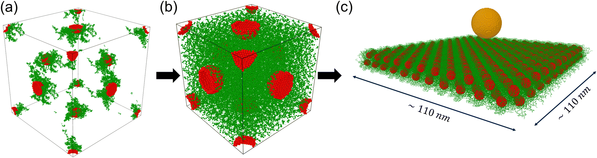 | ||
| Fig. 1 Steps of creating the thin film. (a) Four PGNs are positioned in the FCC unit cell, where the polymer is grafted onto the nanoparticle surface. Self-avoiding random walk algorithm is used to generate polymer beads. (b) A series of equilibration protocols are applied to match the density and extend the polymer grafts. (c) The cubic cell is replicated to make the thin film and a bullet is added for the LIPIT simulations. | ||
We loosely mimic micro-ballistic experiments called the laser-induced particle impact test (LIPIT) in our simulations. More details about the experimental setups can be found in ref. 22 and 23. In the simulation, a 10 nm radius (Rb) bullet is created by assembling beads into a sphere. The bullet beads are arranged in FCC lattice with 7.2 Å spacings, and the bead weight is kept at 96 gm mol−1 to mimic the density of the diamond.25,29 Initially, the bullet is placed at 5 nm above the thin film, and its velocity is set at 1.4 km s−1 (Fig. 1c), the minimum velocity required to perforate every thin film studied herein. The system is integrated under constant energy NVE simulation, which is run until the bullet fully penetrates the film. At the interval of 20 timesteps (80 fs), the bond length of the PMMA backbones is checked. Those that exceed a critical bond length (Γb, 1.17 times the equilibrium length) are deleted, including the associated angle and dihedral interactions. The parametric value for Γb is obtained from our previous work25 by comparing results with the ReaxFF force field,32 which has detailed atomistic bond-breaking definitions. Throughout the simulation, various attributes such as the bullet's center of mass (COM), kinetic energy, thin film's bond, angle, and pair energy are tracked and used for analysis. Ballistic performance metrics, penetration energy, Ep (Ep = Ki − Kf) and specific penetration energy, 
 are calculated for all systems. Here, Ki and Kf are the bullet's initial and final kinetic energy. ρ, and h are the thin film's density, and thickness, respectively, and Rb represents the bullet's radius.
3. Results and discussion
3.1 Thin film's properties
We look at the density (ρ), thickness (h), and nanoparticle weight fraction (ϕwtNP) for four NP core types and 12 distinct graft lengths. The density decreases with increasing graft lengths, N, for every core type (Fig. 2a). This behavior is consistent with our previous result on bulk PGNs.17 However, the drop is significantly higher for heavier NP cores, i.e., Au and cellulose. At higher graft lengths, the density is plateaued towards the bulk density of PMMA (ρ = 1.18 gm cc−1). The density directly correlates with the inter-NP spacings, which increases with longer chains (see Fig. S3, ESI†). The density pattern also influences the film's ballistic performance, which we discussed in the later sections. | ||
| Fig. 2 Evolution of (a) density (ρ), (b) film thickness (h), and (c) nanoparticle weight fraction (ϕwtNP) with graft chain lengths for different types of nanoparticle cores (indicated by different colors). The error bar represents the standard deviation from three different trials. A fit is provided in the density plot for the eyes. The core types have minimal effects on h; hence, one NP core type is plotted. A power law relation is fitted with the thickness data. | ||
The film's thickness, h, gradually increases with graft length irrespective of the core type (Fig. 2b). Again, the film thickness depends on inter-NP spacings. The relation between h and N follows a power law scaling (h ∼ N0.49). The nanoparticle weight fraction, ϕwtNP, is calculated by dividing the weight of all nanoparticle cores by the total weight of the beads in the simulation box (Fig. 2c). As expected, heavier NP cores lead to higher ϕwtNP, whereas longer grafts reduce ϕwtNP.
3.2 Ballistic performance
We evaluate the ballistic performance of thin films in terms of the penetration energy (Ep) and specific penetration energy ( ). Two prominent patterns are observed in Ep behavior (Fig. 3a). First, the longer chains help to increase Ep, which indicates a higher amount of energy absorption. The energy absorption by polymer grafts and nanoparticles is further analyzed in the next subsection. Secondly, PGNs with different core types behave differently for short graft systems but ultimately converge to the same curve as N increases. Initially, the Ep decreases for PGNs with short grafts and heavier NP cores. After a certain graft length, the Ep starts to increase again. The transition point between them reduces to shorter chain lengths as the NP core weight is reduced (50, 40, and 30 for Au, cellulose, and Fe3O4, respectively), and the lightest SiO2 core PGNs do not show the transition.
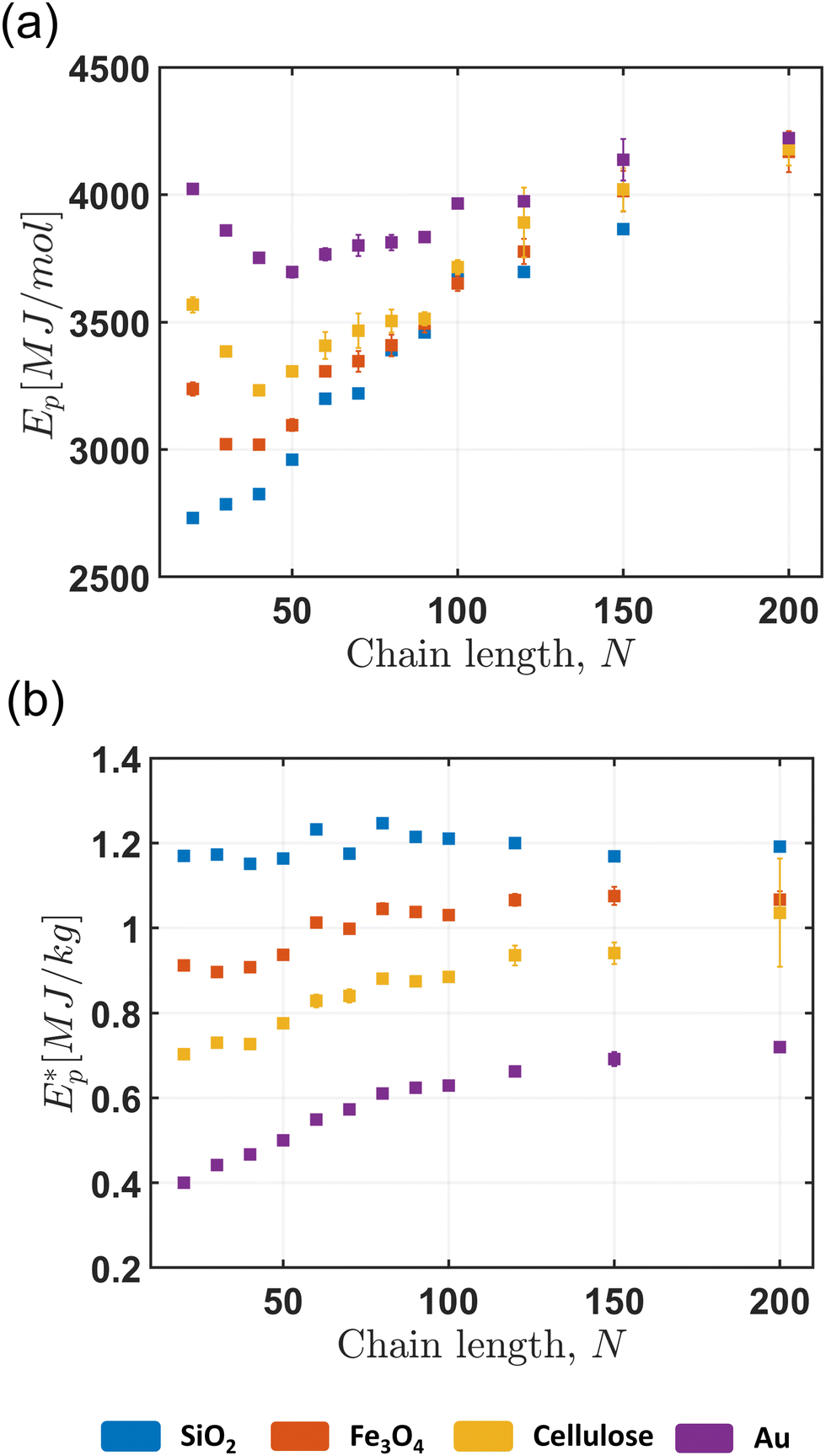 | ||
Fig. 3 (a) Penetration energy (Ep), and (b) specific penetration energy ( ) with graft chain lengths for different nanoparticle core types (indicated by different colors). The error bar represents the standard deviation from three different trials. ) with graft chain lengths for different nanoparticle core types (indicated by different colors). The error bar represents the standard deviation from three different trials. | ||
Similarly, the behavior of  can be deciphered into the effect of graft lengths and NP core types (Fig. 3b). With increasing graft lengths, the
  increases and becomes constant when N crosses the entanglement limit (Ne = 90). This trend differs slightly from experimentally observed systems, where
  shows linear dependence with N.8 Since we are sampling a small range of N (0 < N < 2Ne), the apparent increase of
  is missed. The pattern with NP core type is opposite to what we see for Ep. Here, the lighter silica PGNs have higher
  (∼1.2 MJ kg−1) than heavier gold PGNs (∼0.56 MJ kg−1); ∼2 fold increase. The
  considers the weight of the film under the bullet. Thus, it can be concluded that the NP core weight is the reason behind the reduction. The
  of our system ranges from 0.4 to 1.3 MJ kg−1, which matches quite well with other MD and experimental LIPIT studies of MLG,22,28 PMMA,22,25 PC,18 metals,22,27 and PGNs.8,9
3.3 Effect of cohesive energy density
We divide the into three regimes based on the graft lengths and calculate the volume normalized inter-PGN cohesive energy density, γPGN. It is the total non-bonded energy between a single PGN and its neighbors, normalized by the average PGN volume. The Fe3O4 PGNs are chosen as a representative, and the three regimes are shaded with different colors (Fig. 4a). The first regime is the short graft regime, where the grafted chains are in the concentrated polymer brush (CPB) state and have very limited interpenetration with their neighboring PGNs due to overcrowding. The second one is the interpenetration graft regime, where grafted chains are long enough to enter into the semi-dilute polymer brush (SDPB) regime.14,15 Here, polymer chains are free enough to interpenetrate neighboring PGNs. Greater interpenetration leads to a steep increase in γPGN, which, in turn, improves energy absorption (Fig. 4b). The transition point between the short and interpenetration regime varies with NP core weight, as the opposite trends between ρ (Fig. 2a) and γPGN starts competing. The final regime is the entangled graft regime, which starts when the average number of kinks per chain exceeds 1 (N > Ne). In this regime, the grafted chains start to entangle, which reduces interpenetration as well as the γPGN. It leads to a constant
  in the regime. It should be noted that the trend of
  with N (or h) in the PGN system is completely different than polymer melts,25 where h can be increased without changing ρ. For our system, ρ and h are coupled with the N.
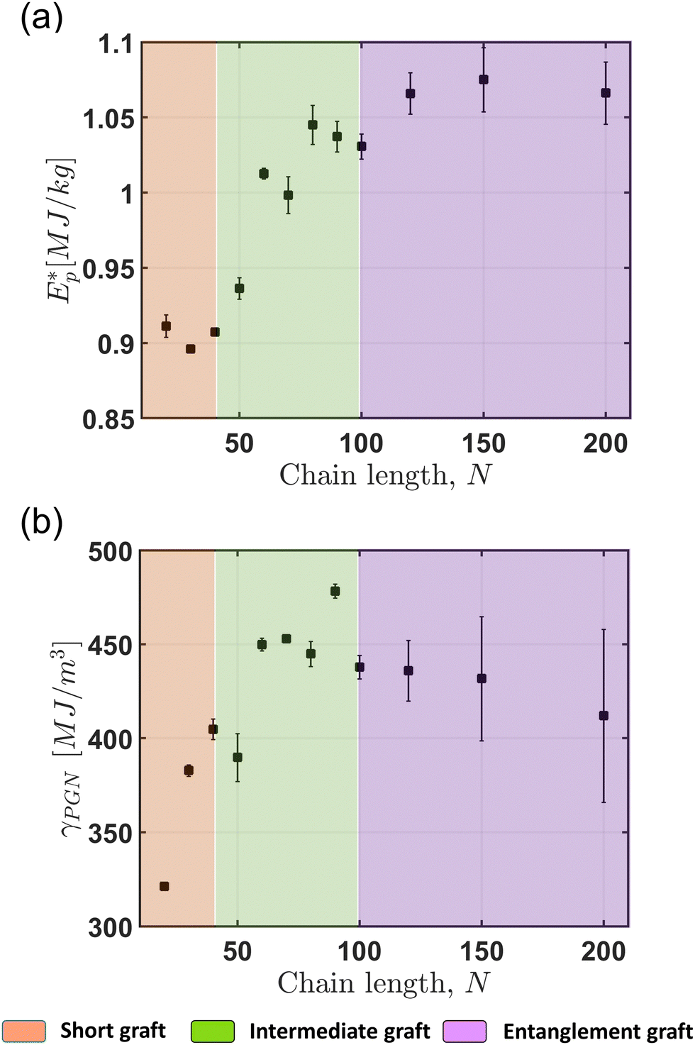 | ||
Fig. 4 (a) Specific penetration energy  , and (b) cohesive energy density (γPGN) for Fe3O4 NP core PGNs. The , and (b) cohesive energy density (γPGN) for Fe3O4 NP core PGNs. The  and γPGN are divided into three different regimes: (i) short graft, (ii) intermediate graft, and (iii) entangled graft. The error bar represents the standard deviation from three different trials. and γPGN are divided into three different regimes: (i) short graft, (ii) intermediate graft, and (iii) entangled graft. The error bar represents the standard deviation from three different trials. | ||
3.4 Failure processes & energy absorption
We look at the snapshots of the films when the bullet passes through (Fig. 5) to study the failure process. The mechanism changes as the N increases; at the shortest graft, N = 20, individual PGNs are fragmented out from the film due to low cohesion between them. During intermediate graft length (N = 40 and 80), chains start pulling out with the displaced PGNs, and the mechanism changes from fragmentation to chain pull-out. Similar patterns were observed by both Chen et al.8 and Bowman et al.20 in PMA-SiO2 PGN and PS thin films, respectively. In PMA-SiO2 PGN, the ballistic failure mechanism changes from chain segment pull-out to disentanglement around 30 kg mol−1 graft weight. On the other hand, the mechanism changes as the bullet speed increases, in the case of PS thin film. These indicate the failure process is dominated by how ballistic energy is transferred to the film.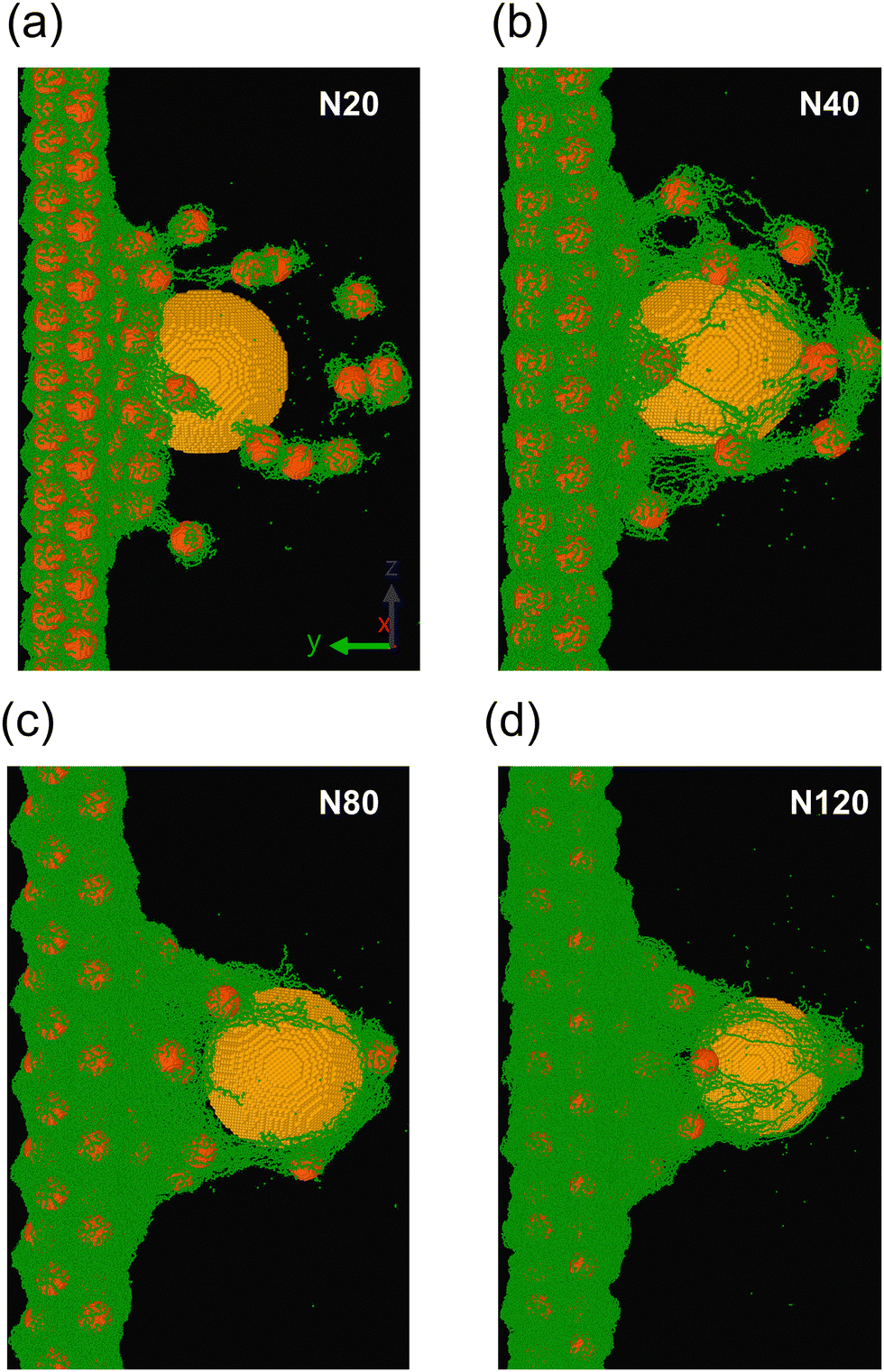 | ||
| Fig. 5 Failure snapshots of Fe3O4 PGNs with (a) N = 20, (b) N = 40, (c) N = 80, and (d) N = 120. The color indicates different beads: green – polymer, red – NP core, and yellow – bullet. | ||
Since the failure process is dominated by energy absorption, we examine fractional energy absorption by the nanoparticle cores (ENP) and polymer grafts (EPol) (Fig. 6). The bond-breaking protocol is employed to compute the energy lost due to bond-breaking (EBB). Here, we see the distinct effect of NP core weight and grafted chain length. The ENP reduces gradually with increasing chain length. Due to the reduction in ϕwtNP, energy absorption by grafted polymers becomes prevalent. In the short graft regime, the NP core controls the failure. The primary dissipation pathway for NP core is rigid body displacements. The energy split between ENP, and Epol changes for different NP core types. ENP reduces gradually for heavier NP cores. This finding might seem counter-intuitive as the heavier Au NP cores will have higher acoustic impedance and better momentum transfer. However, since the mass (MAu) of Au NP is higher, the NP velocity (VAu) will be lower compared to polymer beads. The energy has a quadratic dependence on velocity, indicating the energetic contribution from Au NP will be lower than that of polymers. Conversely, a larger difference between impedance ensures better energy dissipation, as seen from previous works,49,50 which is why ballistic materials are generally layered up. All these traits are visible in this work. The Au-PGNs have the highest Ep among all the PGNs studied herein, and the energetic contribution from NP core (ENP) is lower than the polymers (EPol). The energetic contribution of bond scission, EBB, stays constant for different graft lengths and core types (EBB ∼ 2.5%). This makes sense as the bond scission becomes the predominant failure mechanism when N > 8Ne, which is outside of our design range.8,35 Interestingly, the fraction of broken backbone bonds increases with heavier NP core. However, since Ep also increases with heavier NP cores, there is not a clear effect on the fractional energetic contribution of bond scission. A similar remark can be made about longer grafts, where both the number of bond scissions (Nb) and Ep grow proportionally (see Fig. S6, ESI†).
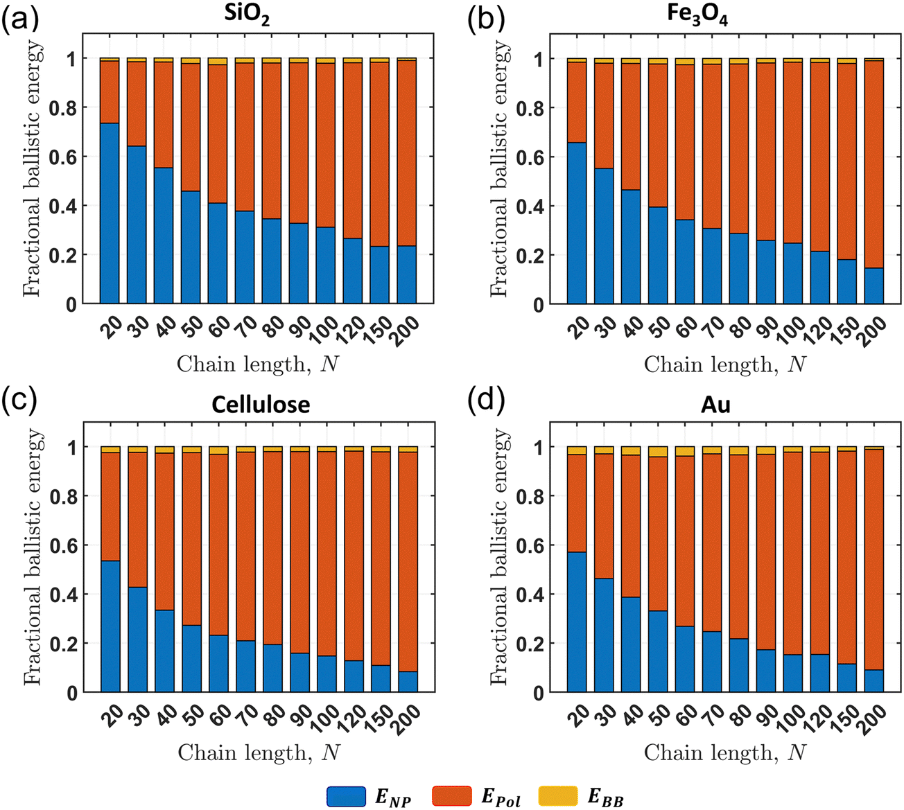 | ||
| Fig. 6 Fractional energy absorbed by NPs, ENP, and polymer grafts, Epol, and lost due to bond scission, EBB, with increasing graft length for (a) SiO2, (b) Fe3O4, (c) cellulose, and (d) Au PGNs. | ||
The NP core movement is a significant energy absorption mode at short graft regime. Hence, we further compute their average displacement (dUNP) and the fraction of displaced NP cores (ϕdUNP) after the bullet passes through the thin film. It should be noted that the number of NP cores changes with graft length due to the constant dimensions of the mobile region. Hence, ϕdUNP reveals the fraction of NP cores that displace in different PGNs. The displacement is calculated by considering the core position at the start of the simulation prior to deformation, and also as the bullet passes through the film. The NPs with more than 200 Å and less than 20 Å displacement are ignored. The upper limit is added because PGNs can stick to the bullet and displace a large distance after the bullet goes through the film and traverses unimpeded. Similarly, some NP cores only move slightly due to thermal vibration, which is the reason for the lower threshold. The values of these two limits are chosen by looking heuristically based on trajectory analyses. Fig. S8 (ESI†) shows spatial distribution of NP core displacements and velocity. The dUNP is calculated by taking the mean of all displacement values. NP cores around the impact zone have considerably higher displacements, with both displacement and velocity decaying radially out from the impact zone. By providing the spatial variation of NP displacements, this analysis provides an estimate of the activated zone due to impact. Fig. 7a reveals dUNP increases slightly with increasing graft length and then reduces significantly. In intermediate graft regime, the higher dUNP leads to increase in  (see Fig. S9, ESI†). Moreover, a higher fraction of NPs (ϕwtNP) participate in energy dissipation (Fig. 7b) in this regime as the cohesion between individual PGNs increases. Fig. 7c shows the effect of NP core weight. The dUNP decreases as the core becomes heavier in both the short and intermediate graft regimes. In the entangled graft regime, both dUNP and ϕdUNP reduce significantly because of the reduction of cohesion and increase in inter-NP distance (see Fig. S3, ESI†); as a result, the effect of NP core weight diminishes.
 | ||
| Fig. 7 (a) Average displacement of the NP core after the bullet impact, dUNP, (b) fraction of NP cores displaced, ϕdUNP, and (c) comparison of dUNP among four different cores and at three different graft lengths. One graft length is chosen from every regime mentioned in Fig. 4. The error bar represents the standard deviation from three different trials. | ||
3.5 Performance of PGN thin films
We create Ashby plots to compare thin film's ballistic performance based on the Ep and . Fig. 8a shows the dependence of Ep on ρ. The Ep of short grafted PGNs follows ∼ρ0.5 relationship, where the fragmented PGNs move with the bullet, indicating inelastic collisions. The Ep of different NP cores with intermediate and entangled grafts follow varying slopes and merge to a single point (Ep = 4660 MJ mol−1, ρ = 1.15 gm cc−1) as we decrease ρ. The point matches the density of the PMMA melt. This trend makes perfect sense, as ρ tends towards the density of PMMA melt with increasing N. Hence, the point indicates the Ep of PGNs at the limit of the polymer melt.
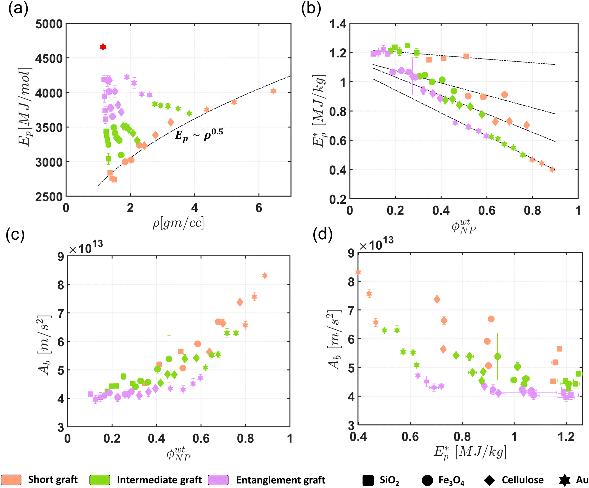 | ||
Fig. 8 Ashby plots of (a) Epvs. ρ, (b)  vs. ϕwtNP, (c) Abvs. ϕwtNP, and (d) Abvs. vs. ϕwtNP, (c) Abvs. ϕwtNP, and (d) Abvs. . The dotted line in (a) shows the power law relation between Ep and ρ for short graft PGNs. The red dot indicates the melt limit for PMMA. The fits in (b) indicate the linear relation between ϕwtNP and . The dotted line in (a) shows the power law relation between Ep and ρ for short graft PGNs. The red dot indicates the melt limit for PMMA. The fits in (b) indicate the linear relation between ϕwtNP and  for different NP core systems. NP cores are indicated by different shapes and different colors that specify three graft length regimes. The error bar represents the standard deviation from three different trials. for different NP core systems. NP cores are indicated by different shapes and different colors that specify three graft length regimes. The error bar represents the standard deviation from three different trials. | ||
Next, we measure  against ϕwtNP. The nanoparticle weight fraction, ϕwtNP, encaptures the effect of both NP core weight and grafted chain length, making it a suitable choice. Interestingly,
  has a linear dependence with ϕwtNP with various slopes for different NP core types (Fig. 8b). Since Au cores are the densest, reducing ϕwtNP increases
  significantly. At ϕwtNP = 0 limit,
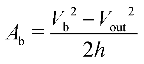
  becomes 1.09–1.23 MJ kg−1, which matches with the PMMA melt's value from our previous work.13 In that work, PMMA with N = 100 is used, and film thickness and bullet velocity are varied from 2–20 nm and 1.2 to 3.0 km s−1, respectively, which essentially covers the ballistic parameters we use in the current study. This indicates that the melt provides better performance than its PGN. However, if we look at the deceleration of the bullet, the importance of adding grafted nanoparticles comes into the picture. The deceleration of bullet while traversing through the film, Ab, is calculated using eqn (1).
 | (1) |
 and Ab have negative and positive relations with ϕwtNP, respectively, creating a conflicting conclusion. Although
  indicates energy absorption per unit weight of a material, it does not reveal the condition of the bullet right after perforating the film. An ideal ballistic-resistant material should have higher energy absorption per weight and can arrest the bullet's movement completely without excessive backface deformation, making Ab an important measure. Hence, in Fig. 8d, we compare
  against Ab, which reveals the trade-off between these two properties. The short graft PGNs provide better deceleration due to higher ϕwtNP but suffer from low energy absorption. On the other hand, PGNs in entanglement graft regime help to increase
  from chain unraveling but do not provide much decelerations. The intermediate grafts are the in-between of these two. The NP cores arrest the bullet, and polymer grafts dissipate energy from chain pull-out, making them suitable for impact resistance applications where back-face deformation is undesirable.
4. Conclusions
In this work, we use micro-ballistic LIPIT simulations to study the impact response of PGN thin films. We systematically vary the graft length and nanoparticle core types. The performance is measured with penetration energy, Ep, and specific penetration energy, , which is then divided into three regimes based on grafted chain length and PGN cohesive energy density. We looked at the failure processes and explained them in terms of energy absorbed by polymer grafts and nanoparticle cores. Finally, the ballistic performance is compared using Ashby plots.
Our finding shows cohesive energy density, γPGN is an important parameter for energy absorption. γPGN stays low when grafted chains are in CPB state and start to increase as chains interpenetrate other PGN's corona. The response of γPGN positively influences  , which achieves maxima before chain entanglement starts (<Ne). The failure processes also change based on which regime the polymer graft falls onto. Short grafted PGNs show fragmentation due to almost no cohesion between them, and the rigid body movement of the NP core absorbs most of the energy. When chain length enters the intermediate graft regime, the film fails by chain pull-out, and polymers predominantly absorb the ballistic energy. The Ashby plots of Ep indicate ballistic processes are inelastic collisions when grafted chains are short and vary with ρ in a power law fashion. When extrapolated further, the different curves for NP cores converge to PMMA melt value for both Ep and
  Ashby plots. Though
  response indicates lower ϕwtNP leads to higher energy absorption per weight, the deceleration, Ab, shows the advantage of adding NPs. Finally, PGNs with intermediate grafted chains simultaneously show relatively higher
  and Ab, making them a suitable choice for ballistic applications. This work can be extended further by studying the effect of NP core radius and grafting density. Ultimately, the generated data from simulations can lead to meta-models that can be used to rapidly explore the complex design space and locate optimized parameters for better ballistic performance.
Author contributions
Subhadeep Pal: conceptualization (lead); data curation (lead); formal analysis (lead); investigation (lead); methodology (lead); validation (lead); visualization (lead); writing – original draft (lead); writing – review & editing (equal). Sinan Keten: formal analysis (equal); funding acquisition (lead); investigation (equal); project administration (lead); resources (lead); supervision (lead); writing – review & editing (equal).Data availability
The data supporting this article have been included as part of the ESI.†Conflicts of interest
There are no conflicts to declare.Acknowledgements
This work was supported by the Army Research Office (Grant No. W911NF2210287) and the National Science Foundation (Grant No. DMR-2226081). Access to a supercomputing grant from the Quest High-Performance-Computing System at the Northwestern University is also acknowledged. S. P. acknowledges the support from the International Institute for Nanotechnology at the Northwestern University.Notes and references
- J. B. Hooper and K. S. Schweizer, Macromolecules, 2006, 39, 5133–5142 CrossRef CAS.
- A. C. Balazs, T. Emrick and T. P. Russell, Science, 2006, 314, 1107–1110 CrossRef CAS PubMed.
- S. K. Kumar, N. Jouault, B. Benicewicz and T. Neely, Macromolecules, 2013, 46, 3199–3214 CrossRef CAS.
- P. Akcora, H. Liu, S. K. Kumar, J. Moll, Y. Li, B. C. Benicewicz, L. S. Schadler, D. Acehan, A. Z. Panagiotopoulos, V. Pryamitsyn, V. Ganesan, J. Ilavsky, P. Thiyagarajan, R. H. Colby and J. F. Douglas, Nat. Mater., 2009, 8, 354–359 CrossRef CAS PubMed.
- D. Parisi, E. Buenning, N. Kalafatakis, L. Gury, B. C. Benicewicz, M. Gauthier, M. Cloitre, M. Rubinstein, S. K. Kumar and D. Vlassopoulos, ACS Nano, 2021, 15, 16697–16708 CrossRef CAS PubMed.
- M. Jhalaria, Y. Cang, Y. Huang, B. Benicewicz, S. K. Kumar and G. Fytas, Phys. Rev. Lett., 2022, 128, 187801 CrossRef CAS PubMed.
- C. R. Bilchak, Y. Huang, B. C. Benicewicz, C. J. Durning and S. K. Kumar, ACS Macro Lett., 2019, 8, 294–298 CrossRef CAS PubMed.
- S. H. Chen, A. J. Souna, S. J. Stranick, M. Jhalaria, S. K. Kumar, C. L. Soles and E. P. Chan, Soft Matter, 2022, 18, 256–261 RSC.
- J. Hyon, M. Gonzales, J. K. Streit, O. Fried, O. Lawal, Y. Jiao, L. F. Drummy, E. L. Thomas and R. A. Vaia, ACS Nano, 2021, 15, 2439–2446 CrossRef CAS PubMed.
- T. Lafitte, S. K. Kumar and A. Z. Panagiotopoulos, Soft Matter, 2014, 10, 786–794 RSC.
- D. Meng, S. K. Kumar, J. M. D. Lane and G. S. Grest, Soft Matter, 2012, 8, 5002–5010 RSC.
- J. G. Ethier and L. M. Hall, Macromolecules, 2018, 51, 9878–9889 CrossRef CAS.
- Y. Zhu, A. Giuntoli, W. Zhang, Z. Lin, S. Keten, F. W. Starr and J. F. Douglas, J. Chem. Phys., 2022, 157, 094901 CrossRef CAS PubMed.
- N. K. Hansoge, A. Gupta, H. White, A. Giuntoli and S. Keten, Macromolecules, 2021, 54, 3052–3064 CrossRef CAS.
- N. K. Hansoge, T. Huang, R. Sinko, W. Xia, W. Chen and S. Keten, ACS Nano, 2018, 12, 7946–7958 CrossRef CAS PubMed.
- A. Moussavi, S. Pal, Z. Wu and S. Keten, J. Chem. Phys., 2024, 160, 134903 CrossRef CAS PubMed.
- Z. Wu, S. Pal and S. Keten, Macromolecules, 2023, 56, 3259–3271 CrossRef CAS.
- J. A. Rogers, K. Xaio, P. Mead, C. U. Pittman Jr, J. W. Wilkerson, E. L. Thomas and T. E. Lacy Jr, Eng. Archive, 2024 DOI:10.31224/3516.
- H. L. White, A. Giuntoli, M. Fermen-Coker and S. Keten, Carbon, 2023, 215, 118382 CrossRef CAS.
- A. L. Bowman, E. P. Chan, W. B. Lawrimore and J. K. Newman, Nano Lett., 2021, 21, 5991–5997 CrossRef CAS PubMed.
- J. Cai, C. Griesbach and R. Thevamaran, ACS Nano, 2021, 15, 19945–19955 CrossRef CAS PubMed.
- J.-H. Lee, P. E. Loya, J. Lou and E. L. Thomas, Science, 2014, 346, 1092–1096 CrossRef CAS PubMed.
- J.-H. Lee, D. Veysset, J. P. Singer, M. Retsch, G. Saini, T. Pezeril, K. A. Nelson and E. L. Thomas, Nat. Commun., 2012, 3, 1164 CrossRef PubMed.
- D. Veysset, J.-H. Lee, M. Hassani, S. E. Kooi, E. L. Thomas and K. A. Nelson, Appl. Phys. Rev., 2021, 8, 011319 CAS.
- Y. Zhu, A. Giuntoli, N. Hansoge, Z. Lin and S. Keten, J. Mech. Phys. Solids, 2022, 161, 104808 CrossRef CAS.
- A. Giuntoli, N. K. Hansoge and S. Keten, Extreme Mech. Lett., 2020, 41, 101038 CrossRef.
- Z. Meng and S. Keten, J. Appl. Mech., 2018, 85, 121004 CrossRef.
- R. A. Bizao, L. D. Machado, J. M. de Sousa, N. M. Pugno and D. S. Galvao, Sci. Rep., 2018, 8, 6750 CrossRef PubMed.
- Z. Meng, A. Singh, X. Qin and S. Keten, Extreme Mech. Lett., 2017, 15, 70–77 CrossRef.
- M. A. N. Dewapriya and S. A. Meguid, Comput. Mater. Sci., 2019, 170, 109171 CrossRef CAS.
- M. A. N. Dewapriya and R. E. Miller, Comput. Mater. Sci., 2021, 195, 110504 CrossRef CAS.
- A. C. T. van Duin, S. Dasgupta, F. Lorant and W. A. Goddard, J. Phys. Chem. A, 2001, 105, 9396–9409 CrossRef CAS.
- S. Pal, K. Dansuk, A. Giuntoli, T. W. Sirk and S. Keten, Macromolecules, 2023, 56, 4447–4456 CrossRef CAS.
- U. Ali, K. J. B. A. Karim and N. A. Buang, Polym. Rev., 2015, 55, 678–705 CrossRef CAS.
- R. P. Wool, J. Polym. Sci., Part B: Polym. Phys., 2005, 43, 168–183 CrossRef CAS.
- D. D. Hsu, W. Xia, S. G. Arturo and S. Keten, J. Chem. Theory Comput., 2014, 10, 2514–2527 CrossRef CAS PubMed.
- S. Askar, L. Li and J. M. Torkelson, Macromolecules, 2017, 50, 1589–1598 CrossRef CAS.
- P. Lu and Y.-L. Hsieh, Carbohydr. Polym., 2010, 82, 329–336 CrossRef CAS.
- X. Ye, C. Zhu, P. Ercius, S. N. Raja, B. He, M. R. Jones, M. R. Hauwiller, Y. Liu, T. Xu and A. P. Alivisatos, Nat. Commun., 2015, 6, 10052 CrossRef PubMed.
- S. Zuppolini, I. C. Maya, L. Diodato, V. Guarino, A. Borriello and L. Ambrosio, Mater. Sci. Eng., C, 2020, 108, 110385 CrossRef CAS PubMed.
- R. J. Tannenbaum, N. Cislo, E. Ruzicka, P. A. Dean, Z. P. Smith, B. C. Benicewicz and S. K. Kumar, Macromolecules, 2023, 56, 3954–3961 CrossRef CAS.
- J. Midya, M. Rubinstein, S. K. Kumar and A. Nikoubashman, ACS Nano, 2020, 14, 15505–15516 CrossRef CAS PubMed.
- K. Ohno, T. Morinaga, S. Takeno, Y. Tsujii and T. Fukuda, Macromolecules, 2007, 40, 9143–9150 CrossRef CAS.
- S. Plimpton, J. Comput. Phys., 1995, 117, 1–19 CrossRef CAS.
- J. S. Shaffer, J. Chem. Phys., 1995, 103, 761–772 CrossRef CAS.
- R. Auhl, R. Everaers, G. S. Grest, K. Kremer and S. J. Plimpton, J. Chem. Phys., 2003, 119, 12718–12728 CrossRef CAS.
- M. Kröger, J. D. Dietz, R. S. Hoy and C. Luap, Comput. Phys. Commun., 2023, 283, 108567 CrossRef.
- S. Wu and R. Beckerbauer, Polym. J., 1992, 24, 1437–1442 CrossRef CAS.
- M. Fejdyś, K. Kośla, A. Kucharska-Jastrzabek and M. Łandwijt, J. Aust. Ceram. Soc., 2021, 57, 149–161 CrossRef.
- M. Grujicic, B. Pandurangan, K. L. Koudela and B. A. Cheeseman, Appl. Surf. Sci., 2006, 253, 730–745 CrossRef CAS.
Footnote |
| † Electronic supplementary information (ESI) available. See DOI: https://doi.org/10.1039/d4sm00718b |
| This journal is © The Royal Society of Chemistry 2024 |