
 Open Access Article
 This Open Access Article is licensed under a Creative Commons Attribution-Non Commercial 3.0 Unported Licence
Cation-regulated MnO2 reduction reaction enabling long-term stable zinc–manganese flow batteries with high energy density†
Yiqiao
Wang
,
Hu
Hong
,
Zhiquan
Wei
,
Dedi
Li
,
Xinru
Yang
,
Jiaxiong
Zhu
,
Pei
Li
,
Shengnan
Wang
and
Chunyi
Zhi
 *
*
Department of Materials Science and Engineering, City University of Hong Kong, 83 Tat Chee Avenue, Kowloon, Hong Kong 999077, China. E-mail: cy.zhi@cityu.edu.hk
First published on 7th January 2025
Abstract
Aqueous Zn–Mn flow batteries (Zn–Mn FBs) are a potential candidate for large-scale energy storage due to their high voltage, low cost, and environmental friendliness. However, the unsatisfactory performance due to the sluggish MnO2 reduction reaction (MnRR) kinetics leads to low discharge voltage (typically <1.7 V) and poor stability (typically <1000 cycles), which hinders their practical application. Here, we successfully achieve a reversible Mn2+/MnO2 reaction by a cation-regulated MnO2 formation/decomposition process. The dual role of Mg2+ addition in locking free water and forming Mg-doped MnO2 compounds with enlarged atomic spacing was revealed, leading to excellent electrolyte stability and highly reversible MnRR. The Zn–Mn FBs with Mg2+ exhibit a high discharge voltage of 1.91 V at 20 mA cm−2 and superior long-term stability for over 2600 cycles, thus realizing a considerably high energy density (38.2 mW h cm−2 per cycle and 23.75 W h cm−2 cumulatively). This work underscores the importance of electrolyte engineering to the reversibility of Mn-based reactions and its potential for high power and energy density applications.
Broader contextZinc–manganese batteries are typically dry cells that can be bought from supermarkets. The evolution from non-rechargeable zinc–manganese dry cells to zinc–manganese flow batteries (Zn–Mn FBs) signifies a crucial step towards scalable and sustainable energy storage. Here, we realize Zn–Mn FBs with high reversibility (2600 cycles) and energy density (38.2 mW h cm−2 per cycle and 23.75 W h cm−2 cumulatively). This work propels the transition of traditional supermarket zinc–manganese batteries to flow systems for large-scale energy storage. |
Introduction
Aqueous flow batteries (AFBs) have attracted much interest due to their high safety, flexible design, and long cycling stability, making them suitable for energy storage devices for harvesting renewable intermittent energy such as solar and wind.1–3 Zinc–manganese flow batteries (Zn–Mn FBs) present distinct advantages over other types of flow batteries, such as all-vanadium (VFBs), zinc–bromine (Zn–Br2 FBs), and aqueous organic (AORFBs) due to their high voltage achieved through the Mn2+ to MnO2 reaction, cost-effectiveness, abundance of element, and environmental friendliness.4–6 These features position Zn–Mn batteries as an up-and-coming option in energy storage. Manganese chemistry based on a conversion mechanism has been initially implemented in the flow battery systems.7–12 When paired with the zinc anode, a high theoretical voltage (E0 = 1.991 V) and substantial specific capacity of 616 mA h gMnO2−1 can be potentially achieved.11,13–15 The reaction formula is delineated as follows:| Zn2+ + Mn2+ + 2H2O ⇔ Zn + MnO2 + 4H+ E0 = 1.991 V vs. Zn/Zn2+ |
As shown in Fig. 1(a) of the typical reaction process of Zn–Mn FBs, the oxidation of Mn2+ to MnO2 transpires at the cathode, concurrently with Zn2+ reduction at the anode in the charging sequence. This transformation process of active substance from liquid to solid phase in charging (Fig. 1(b)-1) and conversely dissolution back into the electrolyte during discharge suffers from sluggish kinetics due to the poor electrical conductivity of electrodeposited MnO2.4,14,16 The incomplete decomposition of MnO2 during discharging in conventional acidic Mn-based catholytes leads to the accumulation of MnO2 solids, passivating the cathode and forming “dead Mn” (Fig. 1(b)-2) as the products are flushed by electrolyte flow, thereby lowering the discharge voltage, capacity and cycling stability, and restricting the energy density of Zn–Mn FBs.
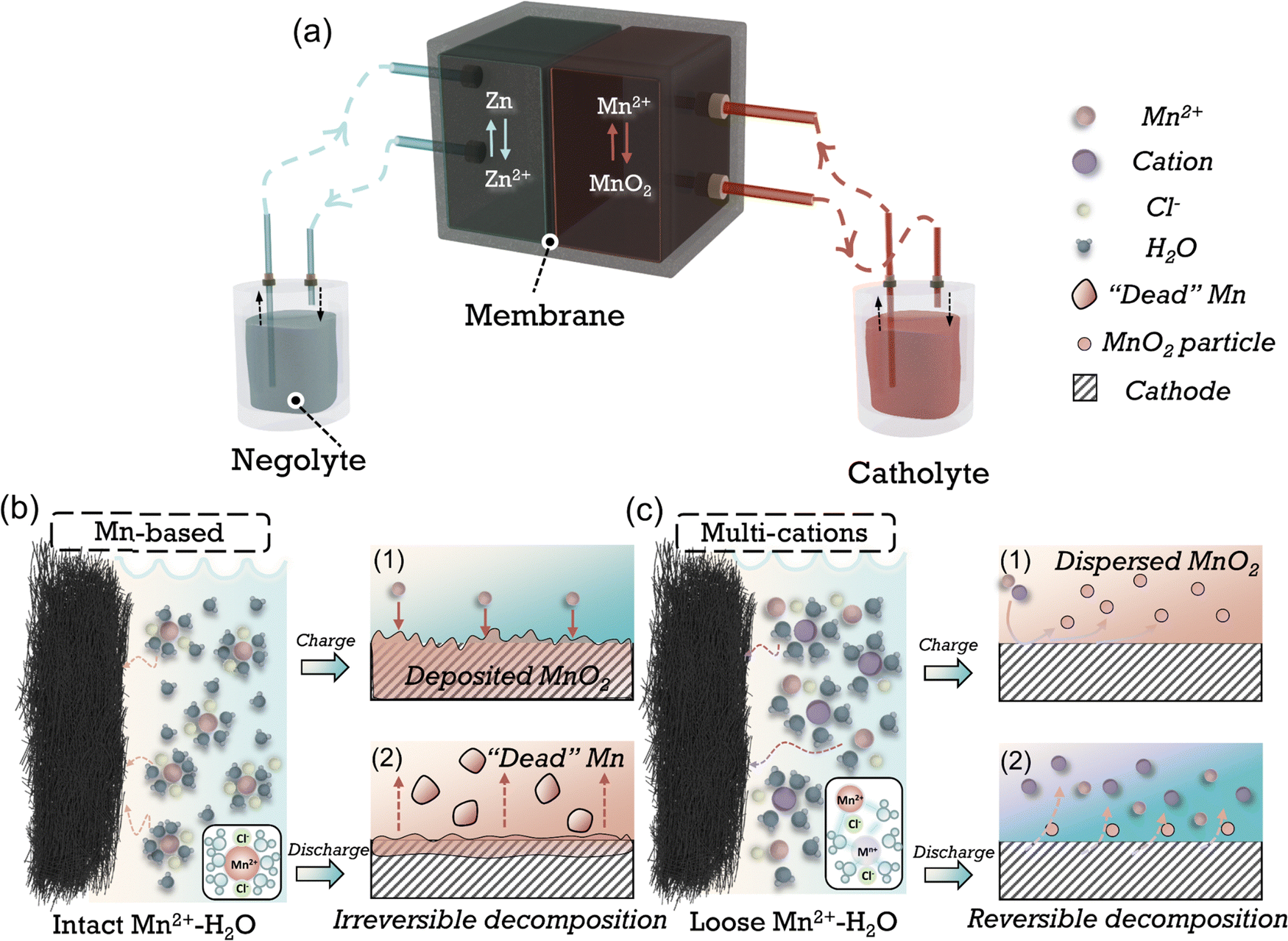 | ||
| Fig. 1 Schematic of the reaction process of the Zn–Mn flow batteries. (a) Shows a Zn–Mn flow battery device. The following magnified chart shows the solvation structure of cation in (b) conventional Mn-based and (c) multi-cationic catholytes, respectively. MnO2 deposition and irreversible decomposition process in Mn-based electrolytes during (b,1) charging and (b,2) discharging. Formation of MnO2 dispersion and reversible decomposition process in multi-cationic electrolytes during (c,1) charging and (c,2) discharging. | ||
Many efforts have been made to improve the reversibility of manganese conversion reactions to improve stability while augmenting the capacity or voltage. Through utilizing the coordination effect of anions with Mn2+, e.g., acetate, Ethylenediaminetetraacetic acid (EDTA), reversibility can be amended by inhibiting the disproportionation of the Mn3+ intermediates and avoiding the formation of “dead Mn”.10,17,18 The acetate-based electrolytes have demonstrated significantly improved cycling stability in flow batteries.9,11 Nevertheless, the diminished proton activity in mild electrolytes and alterations in the coordination structure yields a reduced discharge voltage (<1.6 V vs. Zn/Zn2+). Moreover, the impaired compatibility of zinc anode in acetate electrolytes leads to limited stability, especially at high areal capacity.19,20 An alternative approach involves employing decoupled electrolytes, achieved using acidic and alkaline-based electrolytes as catholytes and anolytes, respectively.21–23 The voltage increased substantially due to the more negative potential of the Zn reaction in alkaline-based electrolytes (−1.199 V vs. SHE).5,24,25 Nevertheless, the decoupled system necessitates incorporating cation-exchange membranes (CEM), anion-exchange membranes (AEM), and a neutral buffer. This introduction substantially elevates the cost and structural intricacy of the batteries. Furthermore, constrained by the migration rate and resistance of ion transport across the membrane, the battery's rate performance and cycling capacity are markedly diminished. In short, developing catholytes with reversible MnO2 reduction reaction (MnRR) while maintaining high voltage, capacity and long-term stability is still challenging.
Ions are usually present in a solvated form in electrolytes, and the solvation structure of the cations can be adjusted by altering the electrolyte components (e.g., cations, anions, solvents, etc.), which in turn affects the reaction kinetics and side reactions that happen at the electrode/electrolyte interphase (Fig. 1(c)).26–28 Cations, as essential constituents of the electrolyte, play a vital role in modulating the hydrogen bonding network29,30 or influencing the structure of MnO2 through doping31 or pre-intercalation.16 By employing appropriate cations, the challenge of sluggish MnRR kinetics can be potentially resolved (Fig. 1(c)-1, 2). However, a consensus has yet to be reached regarding the modulation of the solvation structure of Mn2+ by anions, especially regarding its subsequent impact on the formation/decomposition mechanism of Mn2+/MnO2.
In this work, we successfully demonstrated a reversible Mn2+/MnO2 reaction by modulating the solvation-shell structure of Mn2+ and the structure of electrodeposited MnO2, achieved through a cation-assisted effect. The Zn–Mn FBs with Mg2+ exhibit an impressive high voltage of 1.91 V at 20 mA cm−2 and long-term stability (over 2600 cycles at 20 mA cm−2, 5 mA h cm−2), thus realizing a considerably high energy density of 38.2 mW h cm−2 in a cycle and 23.75 W h cm−2 cumulatively.
Results and discussion
Electrolyte stability and structure characterization
Pure Mn–H electrolyte is made by 1 M Mn salt and 0.2 M HCl in deionized water, and 4 M Mg salt is dissolved into Mn–H electrolyte to form Mn–Mg–H electrolyte. The Mn–H electrolyte is the baseline for comparing electrolyte stability and property variation. Since the reaction potential of MnO2 is similar to the acidic OER potential (E0OER = 1.23 V vs. SHE), the widening of the electrolyte window is required to improve the MnO2 reaction reversibility. The cathodic oxidation reaction and electrolyte stability window are shown by linear scanning voltammetry (LSV) curves, and the corresponding oxygen evolution amounts in Fig. 2(a), where the solid lines indicate the response currents at different potentials and the dashed lines are the corresponding oxygen amount. In the Mn–H electrolyte, the onset potential of the oxidation reaction starts at 0.97 V, accompanied by a few amount of oxygen precipitation (3.7 μmol), indicating a side reaction in the oxidation of MnO2. When the potential increased above 1.62 V, the oxidation current rose sharply, accompanied by the amount of oxygen >100 μmol. In contrast, for the Mn–Mg–H electrolyte, there is almost no oxygen production in the interval from 0.89 V to 1.56 V. After the potential was increased to 2.2 V, only 25.9 μmol of oxygen was precipitated at most, indicating better anti-hydrolysis stability. | ||
| Fig. 2 Stability and structure characterization of Mn–H and Mn–Mg–H electrolytes. (a) Linear scanning voltammetry curves and the corresponding oxygen amount of Mn–H and Mn–Mg–H electrolytes in three-electrode cells at 1 mV s−1. The working electrode is carbon felt, with a counter and reference electrode of Pt plate and Ag/AgCl, respectively. (b) Raman and (c) FT-IR spectra of water, Mn–H and Mn–xMg–H (x = 1, 2, 3, 4 M). The inset image of (b) shows the strong H-bond with DDAA type. Snapshot of (d) Mn–H and (e) Mn–Mg–H from MD simulations. (f) The radial distribution functions and coordination number of cation–Owater. (g) The radial distribution functions and coordination number of cation–Cl−. (h) The visualized solvation structures of Mn2+ and Mg2+ in Mn–H and Mn–Mg–H. (i) The radial distribution functions of water molecules. | ||
To understand the role of Mg2+ in stabilizing the Mn-based electrolytes, Fourier transform infrared (FT-IR) and Raman spectra of pure water and variated Mg2+ concentration in Mn–H electrolytes are collected and compared (Fig. 2(b), (c) and Fig. S1, ESI†). According to the previous report, H2O molecules interact with ions through hydrogen bonds,32 electrostatic forces,33 and charge transfer,34 resulting in a hydration shell. The H-bond and vibrational characteristics of water in the solvated shell are different from those of free water in the bulk phase, so the effect of Mg2+ on the electrolyte H-bond network can be illustrated below: a water molecule can form a maximum of four H-bonds with other H2O molecules by donating protons on the H atom and accepting protons through the lone pair electrons on the O atom35 (Fig. S2, ESI†), corresponding to four different types of H-bond: DA, DAA, DDA and DDAA. The “D” and “A” are the acronyms of the H2O molecules that donate and accept protons, respectively.30 These H-bonds appear as OH symmetric stretching at different positions in the Raman spectrum at ∼3200, 3400 and 3600 cm−1 for DDAA, DA and DDA, respectively.36 The schematic of the four different types of H-bonds is shown in Fig. S3 (ESI†). As shown in Fig. 2(b), the Raman spectrum of Mn–H is similar to that of pure water, while the electrolyte with Mg2+ shows attenuated DDAA peaks that significantly diminish with increasing Mg2+ concentration. The O−H absorption at the lower frequency region (∼3200 cm−1) of the FT-IR spectra37 in Fig. 2(c), corresponding to the strong H-bond of DDAA-related structure, shows a similar trend. These results suggest that massive Mg2+ in the electrolyte disrupts the original H-bond network in Mn–H electrolytes and weakens the strongly hydrogen-bonded water.
To further classify the effect of Mg2+ on the structure of H-bond and the solvation structure of Mn2+, which is crucial to improving the electrolyte stability, classical molecular dynamics (MD) simulations for Mn–H and Mn–Mg–H were performed. Each model contains 2000 water molecules and a corresponding number of ions. The snapshots of the electrolytes with MD simulation in Fig. 2(d) and (e) show a large amount of free water uniformly dispersed in Mn–H. In contrast, in Mn–Mg–H, water molecules are enriched near the cations. The radial distribution functions (RDF) of cation–Ow (oxygen in H2O) as well as cation–Cl are analyzed concerning the apparent coordination number (CN), as shown in Fig. 2(f), (g) and Fig. S4 (ESI†). In Fig. 2(f), the peak of RDF defines the radius of the first hydration shell. In the Mn–Mg–H electrolyte, the distance between Mg2+ and Ow (≈1.97 Å) is closer than Mn2+–Ow (≈2.07 Å). This value (≈2.07 Å) is also slightly larger than the distance of Mn2+–Ow in Mn–H (≈2.03 Å), and the presence of Mg2+ weakens the RDF peak of Mn2+–Ow. These results indicate that water is more tightly bound to Mg2+ than Mn2+, and the hydration shell of Mn2+ is loosened thanks to the addition of Mg2+, which is attributed to the higher charge density of Mg2+. Moreover, more Cl− bound to Mn2+ and enters the first solvation sheath of Mn2+ due to adding MgCl2, further reducing the H2O around Mn2+ (Fig. 2(g)). The visualized solvation structures of Mn2+ and Mg2+ are shown in Fig. 2(h). The Mn–H electrolyte has 5.8 H2O molecules and 0.25 Cl− in the first solvation shell Mn2+. The number of H2O decreases to 4.2, and Cl− increases to 1.6 in the solvation sheath of Mn2+ after adding 4 M MgCl2. The aggregation of water molecules by Mg2+ effectively reduces the H2O amount in the Mn2+ solvation layer and breaks the H-bond structure in Mn–H (Fig. 2(i)). The average number of H-bonds in the first (R1 ≈ 0.97 Å) and second (R2 ≈ 1.75 Å) hydration layer of water molecules is reduced from 2 and 3.5 to 1 and 1.5, respectively. Enabled by the high charge density of Mg2+ in the electrolyte, the amount of free and Mn-solvated water is decreased, which effectively elevates the electrolyte stability at high voltage and suppresses oxygen evolution side reactions (OER) during MnO2 deposition.
Reaction kinetics and reversibility of MnO2 formation/decomposition
In order to study the effect of Mg2+ on the reaction behavior of MnO2, the cyclic voltammetry (CV) behavior of Mn–H and Mn–Mg–H is investigated in the three-electrode system, as shown in Fig. 3(a). Since the MnO2 cathode undergoes two types of reactions, deposition/dissolution and intercalation, at different potentials, an additional 0.5 M ZnCl2 was added to clarify the effect of MnO2 accumulation on the cathodic reaction. It can be observed that the Mn2+ oxidation and MnRR occur mainly at the potential above 1.2 V, with an onset oxidation potential of 1.27 V and reduction peak at 1.25 V, corresponding to the formation and decomposition of MnO2, respectively. The formed MnO2 powder can be observed to diffuse rapidly from the cathode surface into bulk electrolytes (Fig. S5a and b, ESI†), leading to the corresponding CV curves in which the reduction current is much smaller than the oxidation current (Fig. 3(a)). As for the Mn–H system, a completely different reaction behavior is exhibited. Mn2+ is oxidized to form MnO2 in the first positive sweep without MnO2 particles escaping from the catholyte, which remains transparent (Fig. S5c, ESI†).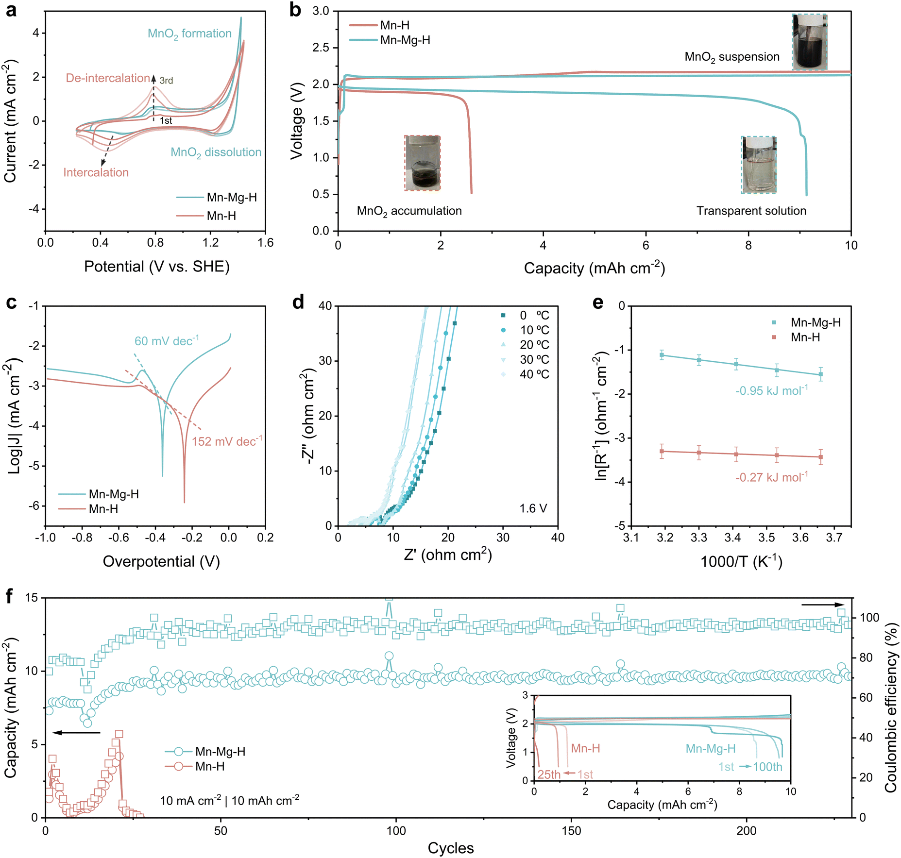 | ||
| Fig. 3 Electrochemical performance of Mn-based reaction in Mn–H and Mn–Mg–H electrolytes. (a) Cyclic voltammetry curves for the first three cycles of Mn–H and Mn–Mg–H electrolyte in three-electrode cell at 1 mV s−1. The working electrode is carbon felt, with a counter and reference electrode of Pt plate and Ag/AgCl, respectively. (b) Initial galvanostatic charge and discharge (GCD) profiles of Zn–Mn FBs with the current density of 5 mA cm−2 in both electrolytes. The inset optical photos are the electrolytes at different states of charge. (c) Tafel plots of the MnRR. (d) Nyquist plot of Zn–Mn flow battery with Mn–Mg–H electrolyte from 0 °C to 40 °C at the constant voltage of 1.6 V to ensure MnRR occurs. (e) Arrhenius fitted curves of Rctvs. temperature in Mn–H and Mn–Mg–H based Zn Mn flow batteries. (f) Cycle performance of Mn–H and Mn–Mg–H based Zn–Mn FBs at 10 mA cm−2 with a cut-off capacity of 10 mA h cm−2. The inset shows the GCD curves corresponding to different cycles. | ||
In contrast, the reduction current corresponding to the decomposition of MnO2 is much smaller than that at oxidation (Fig. 3(a)), and the reduction potential is more negative (1.20 V) compared to 1.25 V, which indicates the poorer reversibility of the MnRR in Mn–H electrolyte. Moreover, in the following scanning process toward lower potentials, the cathode in the Mn–H system shows a pronounced reduction peak at 0.48 V and an emerging oxidation peak at 0.76 V in the second positive scanning, which is sharper with the increase of cycling. This redox behavior corresponds to the cation intercalation/de-intercalation process of the MnO2 electrode, indicating that the MnO2 deposition/dissolution process can hardly occur in the Mn–H system. The accumulation of MnO2 on the cathode induces undesired electrochemical processes.
Different electrochemical behaviors lead to significant differences in battery performance, verified by assembling the Zn–Mn FBs (Fig. S6, ESI†). To mitigate the potential interference of Zn2+ on the MnO2 reaction, as discussed earlier, a cation exchange membrane is employed to separate the cathodic and anodic chambers. Mn–H and Mn–Mg–H are utilized as the catholyte, respectively, while 2 M ZnCl2 with acetate buffer pair is used as anolyte. In Fig. 3(b), the initial charge voltage of both batteries exceeds 2.0 V, and the catholyte of Mn–Mg–H becomes progressively darker as the charge depth increases due to the MnO2 products being washed into the reservoir by the electrolyte flow. In the following discharge process, the Mn–H-based battery terminates at 2.6 mA h cm−2, with some black residual in the reservoir. In comparison, the discharge plateau of Mn–Mg–H-based flow battery reaches 1.91 V in Fig. 3(b), with the initial coulombic efficiency (CE) significantly elevated from 26% (in Mn–H) to 91%. The produced MnO2 in Mn–Mg–H catholytes almost wholly decomposed at the end of the discharge, and the electrolyte becomes clear again (inset photo of Fig. 3(b)). The low capacity of Mn–H-based battery is caused by the sluggish kinetics of MnRR, as evidenced by the Tafel plots in Fig. 3(c). Tafel slope indicates the required overpotential for increasing the reaction current, which is 152 mV dec−1 for Mn–H compared to 60 mV dec−1 for Mn–Mg–H. As for the lower temperature with a poorer mass transfer, the gap between the two electrolytes is even more pronounced. At 0 °C (Fig. S7, ESI†), the Tafel slope of Mn–Mg–H (83 mV dec−1) is much smaller than that of the Mn–H electrolytes (227 mV dec−1). The temperature dynamic electrochemical impedance spectra (EIS) at a constant voltage of 1.6 V and the corresponding equivalent circuit are shown in Fig. 3(d) and Fig. S8 (ESI†). The variation of the reaction resistance (Rct) with temperature was fitted according to the Arrhenius equation, which led to the apparent activation energy (Ea) of MnRR, as shown in Fig. 3(e). The Ea of Mn–Mg–H is −0.95 kJ mol−1 compared to −0.27 in Mn–H, illustrating that MnRR occurs in both electrolytes at 1.6 V with the faster kinetics in Mn–Mg–H-based battery. Superior kinetics bring significantly improved reversibility, reflected in the cycling performance shown in Fig. 3(f). The discharge capacity of Mn–Mg–H-based flow batteries maintains stably at ∼9.5 mA h cm−2 for over 250 cycles. In comparison, the capacity of Mn–H-based batteries decays dramatically in the initial several cycles due to the difficulty of decomposing MnO2 products.
Reduced crystallinity of Mg-doped MnO2 enabling reversible MnRR
Characterizing the composition and structure of the products can help figure out the mechanism of the irreversible MnO2 reaction in the Mn–H electrolytes. In Fig. 4(a), charging products in the Mn–H electrolyte are attached to the surface of carbon fiber (CF) and aggregates on the cathode (Fig. S9a, ESI†). Nevertheless, only fine micron-sized particles (2–5 μm) are deposited on the CF in Mn–Mg–H-based battery (Fig. 4(b)), and the cathode remains fresh (Fig. S9b, ESI†), which is also echoed by the observation of rapid blackening of electrolytes mentioned in Fig. 3(b). X-Ray diffraction patterns in Fig. 4(c) show that the charged products in both electrolytes are γ-MnO2 but with better crystallinity in the Mn–H electrolyte. Considering the low electrical conductivity of MnO2 (∼10−6 S cm−1 at room temperature),38 and the fact that high crystallinity implies high stability of the bulk phase, it is not surprising that MnO2 is difficult to decompose in Mn–H electrolyte (Fig. S10 and S11, ESI†).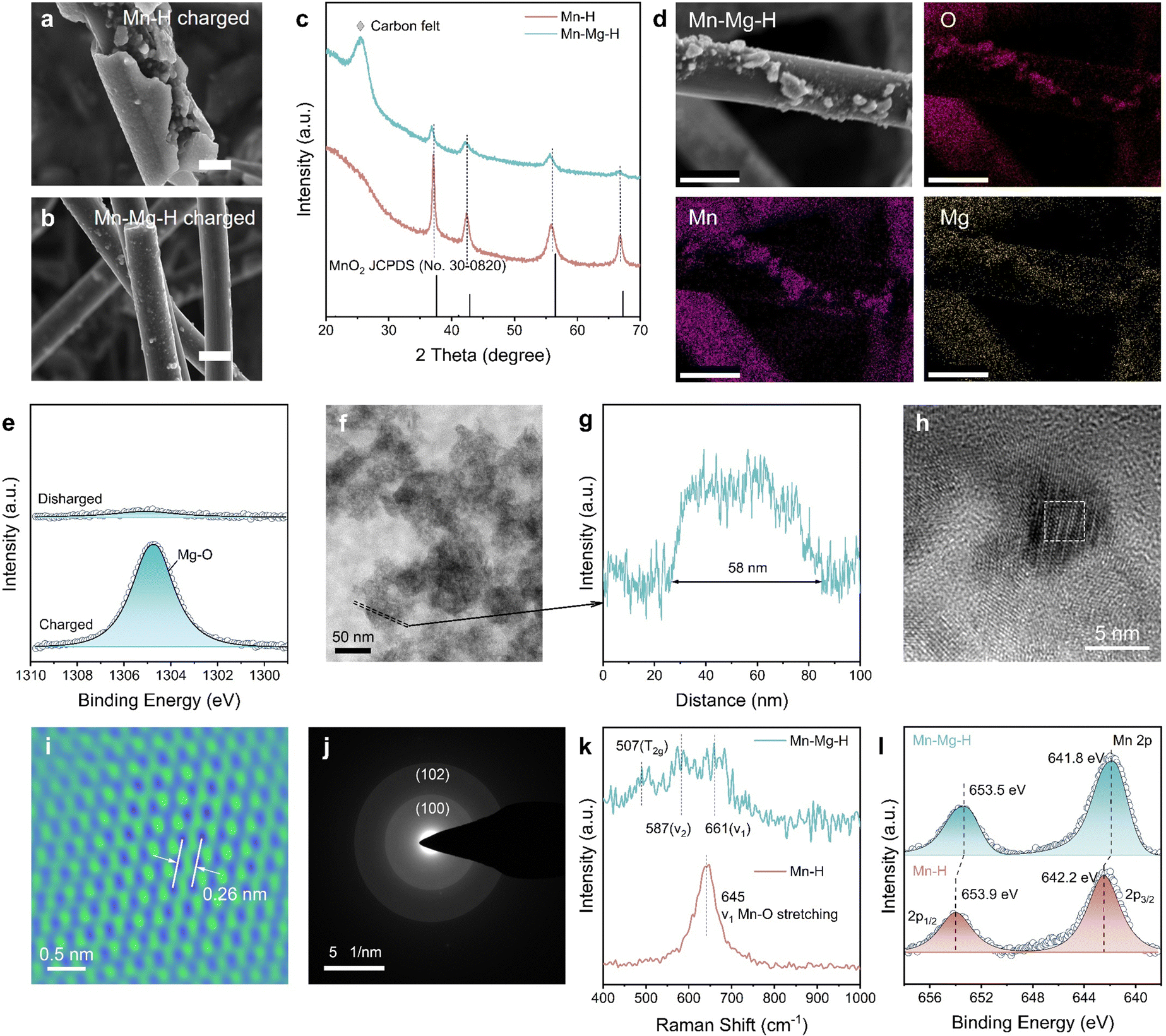 | ||
| Fig. 4 Structure characterization of MnO2 products. Scanning electron microscope (SEM) images of MnO2 products in (a) Mn–H and (b) Mn–Mg–H electrolytes, respectively. The scale bar is uniformly 10 μm. (c) XRD patterns of the discharged cathodes. (d) Energy dispersive spectrometer (EDS) mapping of MnO2 in Mn–Mg–H. The scale bar is uniformly 10 μm. (e) Mg 1s XPS spectra of charged and discharged Mn–Mg–H cathode. (f) TEM image of MnO2 products in Mn–Mg–H. The area enclosed by dashed line corresponds to (g) the thickness profile. (h) HRTEM image of MnO2 products in Mn–Mg–H. (i) Atomic resolution TEM image of the white dashed area in Fig. 4(g). (j) SAED of MnO2 in Mn–Mg–H. (k) Raman spectra of electrodeposited MnO2 in Mn–Mg–H and Mn–H electrolytes. (l) Mn 2p XPS spectra of charged Mn–H and Mn–Mg–H cathode. | ||
Notably, the (100) and (102) peaks of MnO2 in Mn–Mg–H are slightly shifted to a lower angle, and the structural variations are responsible for the differences in the deposition patterns. The EDS mapping, through SEM (Fig. 4(d) and Fig. S12, ESI†), high angle annular dark field-scanning transmission electron microscopy (HAADF-STEM, Fig. S13 and Table S1, ESI†) and the X-ray photoelectron spectroscopy (XPS) spectra of charged/discharged cathodes (Fig. 4(e) and Fig. S14, ESI†) demonstrate the existence of Mg-doping in MnO2. The exact amount of Mg2+ was further determined by the inductively coupled plasma mass spectrometry (ICP-MS), and its relative elemental ratio to Mn2+ was 0.015![[thin space (1/6-em)]](https://www.rsc.org/images/entities/char_2009.gif) :0.985 (Table S2, ESI†). The structure of Mg-doped MnO2 was further characterized by transmission electron microscope (TEM), Raman and XPS in Fig. 4(f)–(l). The diameter of fully dispersed particles is ∼58 nm, as shown in Fig. 4(f) and (g). The High-resolution TEM (HRTEM) in Fig. 4(h) and (i) illustrates the lattice spacing of (100) facet d(100) is increased from 2.42 to 2.60 Å by Mg-doping. This result is also consistent with the diameter of the (100) diffraction ring in the selected area of electron diffraction (SAED) (Fig. 4(j)). Raman spectra in Fig. 4(k) show the structural differences between MnO2 and Mg-doped MnO2. The γ-MnO2 can be viewed as an intergrowth of pyrolusite and ramsdellite, and the defects depend on the relative ratio and arrangement of both structures.39 The Raman spectrum of Mn–H displays a distinct peak at approximately 645 cm−1, indicative of MnO6 octahedra stretching mode. In Mg-doped MnO2 (Fig. 4(k) and Fig. S15, ESI†), three subtle peaks at around 507, 587, and 661 cm−1 suggest a rise in pyrolusite defects within the ramsdellite structure. This increase in defects leads to a heightened electron density around the Mn centers, confirmed by the downshift in the binding energy of the Mn 2p peaks in the XPS spectra, as shown in Fig. 4(l) and Fig. S14, S16 (ESI†). In the Mn–Mg–H catholytes, Mg doping in electrodeposited MnO2 results in expanded atomic spacing and increased defects. These alterations define the structure and morphology of MnO2 products, promoting the formation of more dispersed secondary MnO2 particles in the catholyte prevents the buildup of a passivating layer on the electrode surface, which are pivotal in substantially improving the kinetics of the MnRR.
:0.985 (Table S2, ESI†). The structure of Mg-doped MnO2 was further characterized by transmission electron microscope (TEM), Raman and XPS in Fig. 4(f)–(l). The diameter of fully dispersed particles is ∼58 nm, as shown in Fig. 4(f) and (g). The High-resolution TEM (HRTEM) in Fig. 4(h) and (i) illustrates the lattice spacing of (100) facet d(100) is increased from 2.42 to 2.60 Å by Mg-doping. This result is also consistent with the diameter of the (100) diffraction ring in the selected area of electron diffraction (SAED) (Fig. 4(j)). Raman spectra in Fig. 4(k) show the structural differences between MnO2 and Mg-doped MnO2. The γ-MnO2 can be viewed as an intergrowth of pyrolusite and ramsdellite, and the defects depend on the relative ratio and arrangement of both structures.39 The Raman spectrum of Mn–H displays a distinct peak at approximately 645 cm−1, indicative of MnO6 octahedra stretching mode. In Mg-doped MnO2 (Fig. 4(k) and Fig. S15, ESI†), three subtle peaks at around 507, 587, and 661 cm−1 suggest a rise in pyrolusite defects within the ramsdellite structure. This increase in defects leads to a heightened electron density around the Mn centers, confirmed by the downshift in the binding energy of the Mn 2p peaks in the XPS spectra, as shown in Fig. 4(l) and Fig. S14, S16 (ESI†). In the Mn–Mg–H catholytes, Mg doping in electrodeposited MnO2 results in expanded atomic spacing and increased defects. These alterations define the structure and morphology of MnO2 products, promoting the formation of more dispersed secondary MnO2 particles in the catholyte prevents the buildup of a passivating layer on the electrode surface, which are pivotal in substantially improving the kinetics of the MnRR.
Battery performance of Mn–Mg–H-based Zn–Mn FBs
The enhanced MnRR kinetics notably boost both the rate and cycling performance of the Zn–Mn flow batteries. As shown in Fig. 5(a), the Zn–Mn FBs with Nafion membrane exhibit exceptional rate performance and reversibility at 10 mA h cm−2. The corresponding voltage profiles of Zn–Mn FBs at various rates are shown in Fig. 5(b). After potentiostatic charged at 2.2 V, the discharge voltage reached 2.0, 1.97, 1.91, 1.69 and 1.21 V at 10, 15, 20, 30 and 40 mA cm−2, respectively. Specifically, the 1.91 V platform is the highest voltage reported for Zn–Mn FBs over 20 mA cm−2. Meanwhile, the CE of Zn–Mn FBs maintains stable around 90% from 10 mA cm−2 to 40 mA cm−2. After switching to the initial current density of 10 mA cm−2, the voltage of Zn–Mn FBs is reinstated to 1.98 V, indicating excellent reversibility at high current densities. Furthermore, owing to the improved reversibility and high voltage, the Zn–Mn FBs deliver the highest power density of 52.71 mW cm−2 at 35 mA cm−2 from 10 to 50 mA cm−2 (Fig. 5(c)).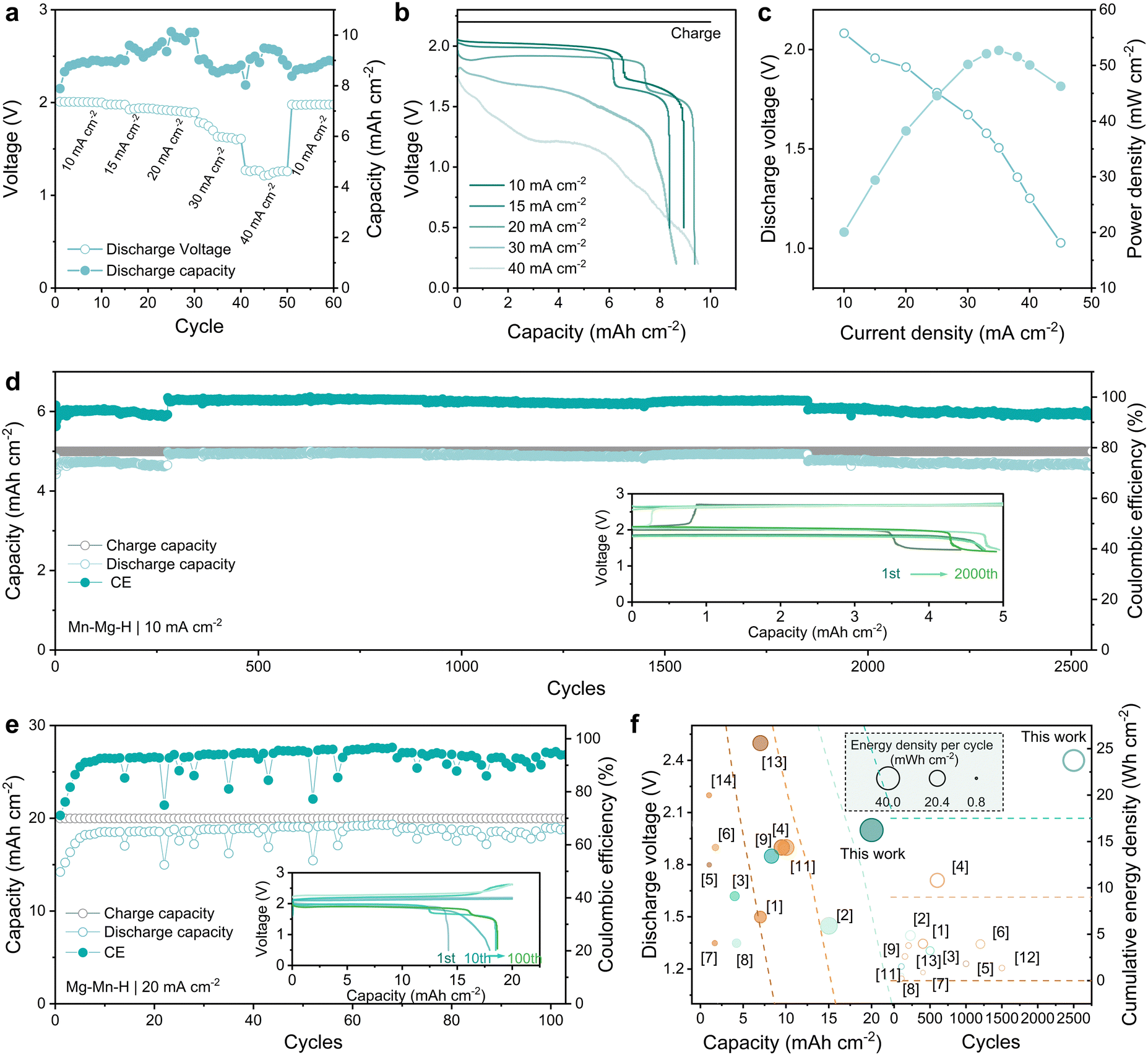 | ||
| Fig. 5 Performance of Zn–Mn FBs with Mn–Mg–H based electrolyte. (a) Rate performance at a constant charging cut-off capacity of 10 mA h cm−2. (b) Voltage–capacity profiles at different current densities. (c) Polarization curve and power density of the flow battery. (d) Long-term cycle performance at 10 mA cm−2, 5 mA h cm−2. The inset graph exhibits voltage profiles at different cycles. (e) The cycling performance of the flow battery at 20 mA cm−2, 20 mA h cm−2 with the inset graph shows the corresponding GCD profiles. (f) Performance comparison of Zn–Mn FBs based on discharge voltage (y-axis) and areal capacity (x-axis). The noted number in Fig. 5(f) corresponds to the reference; only the batteries over 100 cycles are selected for comparison. | ||
Batteries employing Mn–Mg–H electrolytes demonstrate remarkable long-term cycle stability. As illustrated in Fig. 5(d), when operating with a cut-off capacity of 5 mA h cm−2 at 10 mA cm−2, the flow battery consistently performs over 2600 cycles with a high CE of over 95% while maintaining a discharge voltage above 1.90 V. The low-potential plateau (∼1.5 V) that gradually becomes apparent with cycling may be related to the proton intercalation behavior triggered by the accumulation of a few amounts of MnO2, which, together with the zinc corrosion on the negative side, also contributes to the failure of the batteries (Fig. S17–S19 and Table S3, ESI†). In addition, as shown in Fig. 5(e), when operating at tighter conditions of higher capacity (20 mA h cm−2) and elevated current density (20 mA cm−2), the Zn–Mn FBs still exhibit superior cycling stability for over 100 cycles (CE ∼ 94%). The inset graph of GCD profiles in Fig. 5(e) shows the settled voltage platform at 1.90 V, suggesting the outstanding reversibility of Mn2+/MnO2 conversion reaction. Additionally, thanks to the Mn–Mg–H electrolyte with reduced H-bond strength, it is operable over a wider temperature range. The Mn–Mg–H based Zn–Mn FBs maintained stability for 100 cycles at both 80 °C and 0 °C (Fig. S20, ESI†), exhibiting considerable resistance to temperature fluctuation. The voltage, capacity and stability improvements contribute to the energy density of Zn–Mn FBs. The performance of reported Zn–Mn FBs in recent years has been meticulously cataloged, with a particular emphasis on their energy density. This comprehensive evaluation is illustrated in Fig. 5(f) and detailed in Table S3 (ESI†), highlighting significant advancements in this domain. The Zn–Mn FBs utilizing Mn–Mg–H catholytes present noticeably high energy density (38.2 mW h cm−2 per cycle and 23.75 W h cm−2 cumulatively). Such exceptional performance demonstrates the effectiveness of improving the reversibility of the MnO2 conversion reaction through the dual function of intense hydration and doping of Mg2+.
Conclusion
In summary, we demonstrated the cation-assisted Mn2+/MnO2 reaction with significantly improved MnO2 reduction reaction (MnRR) kinetics, enabling high voltage and long-term stable Zn–Mn FBs. FT-IR, Raman and MD simulations showed the vigorous hydration of Mg2+ to enhance the electrolyte stability upon MnO2 deposition above 2.0 V. The Mg-doped MnO2 characterized by EDS, HR-TEM and XPS spectra contain more structural defects and larger atomic spacing, which was easier to decompose and disperse in catholyte, avoiding the cathode passivation due to MnO2 aggregation. The Mg2+-regulated Zn–Mn FBs realize a high discharge voltage above 1.91 V at 20 mA cm−2, and superior cycling stability for over 2600 cycles at 5 mA h cm−2 (10 mA cm−2) and 100 cycles at 20 mA h cm−2 (20 mA cm−2), an exceptional energy density of 38.2 mW h cm−2 per cycle and 23.75 W h cm−2 cumulatively is realized. Our research demonstrates a novel approach to enhancing the performance of Zn–Mn FBs through electrolyte engineering. This approach offers a viable strategy for developing scalable energy storage devices with high power and energy density suitable for practical applications.Data availability
All datasets generated or analyzed during this study are included in the paper and ESI.†Conflicts of interest
There are no conflicts to declare.Acknowledgements
This work is partially supported by a grant from Shenzhen Science and Technology Program (SGDX20211123151002003) and Innovation and Technology Fund (GHP/191/21SZ).References
- Z. Zhao, X. Liu, M. Zhang, L. Zhang, C. Zhang, X. Li and G. Yu, Chem. Soc. Rev., 2023, 52, 6031–6074 RSC
.
- F. Ai, Z. Wang, N.-C. Lai, Q. Zou, Z. Liang and Y.-C. Lu, Nat. Energy, 2022, 7, 417–426 CrossRef
- S. Wang, T. Li, Y. Yin, N. Chang, H. Zhang and X. Li, Nano Energy, 2022, 96, 107120 CrossRef
- H. Pan, Y. Shao, P. Yan, Y. Cheng, K. S. Han, Z. Nie, C. Wang, J. Yang, X. Li, P. Bhattacharya, K. T. Mueller and J. Liu, Nat. Energy, 2016, 1, 1–7 Search PubMed
- C. Zhong, B. Liu, J. Ding, X. Liu, Y. Zhong, Y. Li, C. Sun, X. Han, Y. Deng, N. Zhao and W. Hu, Nat. Energy, 2020, 5, 440–449 CrossRef
- S. Wang, Z. Wang, Y. Yin, T. Li, N. Chang, F. Fan, H. Zhang and X. Li, Energy Environ. Sci., 2021, 14, 4077–4084 RSC
- G. Li, W. Chen, H. Zhang, Y. Gong, F. Shi, J. Wang, R. Zhang, G. Chen, Y. Jin, T. Wu, Z. Tang and Y. Cui, Adv. Energy Mater., 2020, 10, 1902085 CrossRef
- N. Liu, K. Mohanapriya, J. Pan, Y. Hu, Y. Sun and X. Liu, J. Electrochem. Soc., 2020, 167, 040517 CrossRef
- C. Xie, T. Li, C. Deng, Y. Song, H. Zhang and X. Li, Energy Environ. Sci., 2020, 13, 135–143 RSC
- X. Yu, Y. Song and A. Tang, J. Power Sources, 2021, 507, 230295 CrossRef
- J. Lei, Y. Yao, Z. Wang and Y.-C. Lu, Energy Environ. Sci., 2021, 14, 4418–4426 RSC
- W. Xiang, M. Yang, M. Ding, X. Chen, J. Liu, G. Zhou, C. Jia and G. I. N. Waterhouse, Energy Storage Mater., 2023, 61, 102894 CrossRef
- G. Liang, F. Mo, H. Li, Z. Tang, Z. Liu, D. Wang, Q. Yang, L. Ma and C. Zhi, Adv. Energy Mater., 2019, 9, 1901838 CrossRef
- D. Chao, W. Zhou, C. Ye, Q. Zhang, Y. Chen, L. Gu, K. Davey and S. Qiao, Angew. Chem., Int. Ed., 2019, 58, 7823–7828 CrossRef
- X. Guo, J. Zhou, C. Bai, X. Li, G. Fang and S. Liang, Mater. Today Energy, 2020, 16, 100396 CrossRef
- H. Yang, W. Zhou, D. Chen, J. Liu, Z. Yuan, M. Lu, L. Shen, V. Shulga, W. Han and D. Chao, Energy Environ. Sci., 2022, 15, 1106–1118 RSC
- X. Zeng, J. Liu, J. Mao, J. Hao, Z. Wang, S. Zhou, C. D. Ling and Z. Guo, Adv. Energy Mater., 2020, 10, 1904163 CrossRef
- H. Moon, K.-H. Ha, Y. Park, J. Lee, M.-S. Kwon, J. Lim, M.-H. Lee, D.-H. Kim, J. H. Choi, J.-H. Choi and K. T. Lee, Adv. Sci., 2021, 8, 2003714 CrossRef
- Z. Liu, Y. Yang, S. Liang, B. Lu and J. Zhou, Small Struct., 2021, 2, 2100119 CrossRef
- J. Sun, X. Zheng, K. Li, G. Ma, T. Dai, B. Ban, Y. Yuan, M. Wang, M. Chuai, Y. Xu, Z. Liu, T. Jiang, Z. Zhu, J. Chen, H. Hu and W. Chen, Energy Storage Mater., 2023, 54, 570–578 CrossRef
- B. Kim, Y. S. Kim, D. Dulyawat and C.-H. Chung, J. Energy Storage, 2023, 72, 108337 CrossRef
- D. Chao, C. Ye, F. Xie, W. Zhou, Q. Zhang, Q. Gu, K. Davey, L. Gu and S.-Z. Qiao, Adv. Mater., 2020, 32, 2001894 CrossRef
- C. Liu, X. Chi, Q. Han and Y. Liu, Adv. Energy Mater., 2020, 10, 1903589 CrossRef
- Y. Zhu, Y. Cui, Z. Xie, Z. Zhuang, G. Huang and X. Zhang, Nat. Rev. Chem., 2022, 6, 505–517 CrossRef
- S. Wang, C. Yuan, N. Chang, Y. Song, H. Zhang, Y. Yin and X. Li, Sci. Bull., 2021, 66, 889–896 CrossRef
- D. Wu, L. M. Housel, S. T. King, Z. R. Mansley, N. Sadique, Y. Zhu, L. Ma, S. N. Ehrlich, H. Zhong, E. S. Takeuchi, A. C. Marschilok, D. C. Bock, L. Wang and K. J. Takeuchi, J. Am. Chem. Soc., 2022, 144, 23405–23420 CrossRef PubMed
- H. Chen, C. Dai, F. Xiao, Q. Yang, S. Cai, M. Xu, H. J. Fan and S.-J. Bao, Adv. Mater., 2022, 34, 2109092 CrossRef PubMed
- Y. Deng, H. Wang, M. Fan, B. Zhan, L.-J. Zuo, C. Chen and L. Yan, J. Am. Chem. Soc., 2023, 145(36), 20109–20120 CrossRef PubMed
- U. T. D. Huynh, A. Lerbret, F. Neiers, O. Chambin and A. Assifaoui, J. Phys. Chem. B, 2016, 120, 1021–1032 CrossRef PubMed
- J. Liu, D. Dong, A. L. Caro, N. S. Andreas, Z. Li, Y. Qin, D. Bedrov and T. Gao, ACS Cent. Sci., 2022, 8, 729–740 CrossRef PubMed
- Q. Wang, W. Zhou, Y. Zhang, H. Jin, X. Li, T. Zhang, B. Wang, R. Zhao, J. Zhang, W. Li, Y. Qiao, C. Jia, D. Zhao and D. Chao, Environ. Chem. Lett., 2018, 16, 683–694 CrossRef
- H. Xu and B. J. Berne, J. Phys. Chem. B, 2001, 105, 11929–11932 CrossRef CAS
- J. Åqvist and T. Hansson, J. Phys. Chem., 1996, 100, 9512–9521 CrossRef
- R. Laenen, T. Roth and A. Laubereau, Phys. Rev. Lett., 2000, 85, 50–53 CrossRef CAS
- A. Luzar and D. Chandler, Nature, 1996, 379, 55–57 CrossRef CAS
- Q. Sun, Vib. Spectrosc., 2009, 51, 213–217 CrossRef
- H.-C. Chen, F.-D. Mai, K.-H. Yang, L.-Y. Chen, C.-P. Yang and Y.-C. Liu, Anal. Chem., 2015, 87, 808–815 CrossRef
-
J.-G. Wang, Supercapacitor Design and Applications, IntechOpen, 2016 Search PubMed
- C. Julien, M. Massot, S. Rangan, M. Lemal and D. Guyomard, J. Raman Spectrosc., 2002, 33, 223–228 CrossRef
Footnote |
| † Electronic supplementary information (ESI) available. See DOI: https://doi.org/10.1039/d4ee03385j |
| This journal is © The Royal Society of Chemistry 2025 |