
 Open Access Article
 This Open Access Article is licensed under a Creative Commons Attribution-Non Commercial 3.0 Unported Licence
Visualizing fiber end geometry effects on stress distribution in composites using mechanophores†
Nazmul
Haque
a,
Hao Chun
Chang
b,
Chia-Chih
Chang
b and
Chelsea S.
Davis
 *acd
*acd
aSchool of Materials Engineering, Purdue University, West Lafayette, IN 47906, USA. E-mail: chelsead@udel.edu
bNational Yang Ming Chiao Tung University, Hsinchu, Taiwan
cDepartment of Mechanical Engineering, University of Delaware, Newark, DE, USA
dDepartment of Materials Science and Engineering, University of Delaware, Newark, DE 19716, USA
First published on 14th November 2024
Abstract
Localized stress concentrations at fiber ends in short fiber-reinforced polymer composites (SFRCs) significantly affect their mechanical properties. Our research targets these stress concentrations by embedding nitro-spiropyran (SPN) mechanophores into the polymer matrix. SPN mechanophores change color under mechanical stress, allowing us to visualize and quantify stress distributions at the fiber ends. We utilize glass fibers as the reinforcing material and employ confocal fluorescence microscopy to detect color changes in the SPN mechanophores, providing real-time insights into the stress distribution. By combining this mechanophore-based stress sensing with finite element analysis (FEA), we evaluate localized stresses that develop during a single fiber pull-out test near different fiber end geometries—flat, cone, round, and sharp. This method precisely quantifies stress distributions for each fiber end geometry. The mechanophore activation intensity varies with fiber end geometry and pull-out displacement. Our results indicate that round fiber ends exhibit more gradual stress transfer into the matrix, promoting effective stress distribution. Also, different fiber end geometries lead to distinct failure mechanisms. These findings demonstrate that fiber end geometry plays a crucial role in stress distribution management, critical for optimizing composite design and enhancing the reliability of SFRCs in practical applications. By integrating mechanophores for real-time stress visualization, we can accurately map quantified stress distributions that arise during loading and identify failure mechanisms in polymer composites, offering a comprehensive approach to enhancing their durability and performance.
1. Introduction
In fiber reinforced polymer matrix composites, stresses concentrate near the ends of fibers upon loading. These discontinuities in the reinforcing fibers often lead to highly uneven stress and strain distributions, which can induce crack initiation and ultimate composite failure.1 Understanding the effects of discontinuous reinforcement in loaded polymer composites is crucial for preventing catastrophic material failures. Short fiber-reinforced polymers composites (SFRCs) are widely used in aerospace, automotive, and energy industries due to their high specific strength and stiffness, making them ideal for load-bearing components.2 However, maximizing these inherent strengths and overcoming existing limitations or challenges that currently prevent these composites from achieving their optimal performance and reliability are critical. These challenges often revolve around identifying and mitigating issues related to failure initiation and progression under real-world operating conditions. By addressing these challenges, we can unlock the optimum potential of SFRCs, ensuring they meet or exceed performance expectations in demanding applications.Localized stresses are a primary cause of failure in SFRCs, where stress concentration at fiber ends or tips is particularly problematic.3,4 Microfailures around fiber ends critically affect the overall mechanical properties of composites, making their analysis essential for improving material performance and reliability. In SFRCs, fiber end geometry significantly influences stress transfer and localization. Variations in the shape and material composition of fiber ends generate stress concentrations, with the most severe occurring where there are significant strain mismatches. Sharp fiber ends cause higher stress concentrations compared to rounded tips, leading to inefficient load transfer and reduced composite strength and modulus.5–11 These stress concentrations often lead to interfacial debonding, matrix cracking, or fiber pull-out.12,13 Identifying and mitigating these localized stresses is vital for improving the durability and reliability of SFRCs. Techniques like fragmentation tests, microdebond tests, and fiber pull-out tests assess the bonding strength between the fiber and matrix in fiber-reinforced composites.14–17 Among these, the single-fiber pull-out test is widely used due to its straightforward sample preparation and measurement, where bond strength is measured by the force required to pull-out a fiber embedded in the matrix.18–20 Developing non-destructive techniques to quantify and visualize stress concentrations at fiber ends during these single fiber pull-out tests is essential for advancing SFRCs performance.
Traditionally, most short fibers (specifically glass fibers) are cylindrical and have flat ends with sharp edges due to conventional production methods. Recent advancements now allow for the economical production of round-ended short fibers, enabling the experimental validation of theoretical predictions and more extensive studies on the effects of fiber end geometry.21 Researchers using photoelasticity and finite element analysis (FEA) have demonstrated that stress profiles along fibers vary significantly based on end geometry, with wedge and V-shaped tips showing the highest stress concentrations and semi-circular ends the lowest.22–25 Additionally, studies indicate that composites reinforced with enlarged-end fibers are stronger than those with plain fibers of similar properties and aspect ratios.26–28 These findings align well with experimental photoelasticity measurements, although the geometrical effect of fiber ends on the localized stress profile in the matrix around a single fiber have not been thoroughly examined. Current techniques for stress analysis in composite materials each offer unique advantages but face limitations when capturing localized stresses at the fiber-matrix interface. Digital Image Correlation (DIC) provides valuable strain data on the surface through marker tracking, yet it lacks the ability to measure through-thickness stress variations, limiting its use for 3D internal stress visualization within composites.29 Similarly, photoelasticity relies on polymer chain alignment under polarized light to visualize stress fields and is restricted to transparent or translucent matrices and cannot quantify stress for complex fiber geometries.30 Piezoelectric sensors, while effective for external strain detection, encounter difficulties in detecting localized internal stresses.31 Moreover, several non-destructive testing (NDT) methods are commonly employed for stress visualization in composite systems. Ultrasonic imaging, for instance, provides internal inspection by sending high-frequency sound waves through the material; however, it requires extensive equipment and has limitations in detecting micro-scale stress concentrations near fiber ends.32 Thermography visualizes stress by detecting heat variations caused by material deformation, offering surface-level insights but with limited depth for internal stress profiling.33 Fiber Bragg grating (FBG) sensors measure strain by tracking shifts in reflected light wavelengths along fiber optic lines, enabling localized surface stress mapping but posing challenges in terms of spatial resolution and depth sensitivity.34
One tool that can enable visualization of the localized stresses with enhanced sensitivity is the incorporation of mechanoresponsive materials. Mechanophore-based approaches provide high-resolution, real-time visualization of localized stress at a molecular level. By embedding mechanophores within the polymer matrix, internal stress concentrations near fiber ends can be visualized directly under mechanical load, surpassing the spatial resolution and depth limitations of other NDT methods. Mechanoresponsive materials thus offer a unique, non-destructive pathway for real-time stress mapping, particularly valuable for visualizing and investigating damage and mechanical load distributions in polymeric composites.35–39 Recent advancements in polymer mechanochemistry have introduced mechanoresponsive molecules, known as mechanophores (MPs), as innovative stress sensors.40–44 Mechanophores are force-sensitive molecular units that undergo specific chemical changes in response to mechanical stress, resulting in visible signals such as color changes.39,45 When incorporated into a polymer matrix, mechanophores can provide real-time, molecular detection of stress and damage within the composite material.46–48 For instance, spiropyran (SP), a well-known mechanophore, changes color from colorless to purple under mechanical forces and can revert back to colorless form.49 The mechanochromic properties of SP-based mechanophore materials are influenced by several factors, including the polymeric architecture, the mechanical properties of the matrix, and the structure of the SP molecule itself. SP rings have several functional attachment points where polymers can be covalently linked, affecting how force is transmitted to the SP molecule and leading to the cleavage of the spiro C–O bond as shown in Fig. 1(a). The SP molecule consists of an indoline ring and a chromene ring; effective force transmission to cleave the C–O bond requires both rings to be connected to polymer chains.50,51 Molecular-level detection of stress using SP mechanophores has been intensively studied by Creton and coworkers.52–56 Their work focused on chain fracture in multinetwork polymers to investigate the mechanisms of stress transfer in materials. This approach provided detailed insights into the detection of microscopic cracks and macroscopic necking, highlighting the onset of failure. Recently, our lab has shown that embedding SP into the polymer matrix of fiber reinforced polymer composites allows for the visualization of stress concentrations, enabling early detection of stress localization and potential failure points.57–59
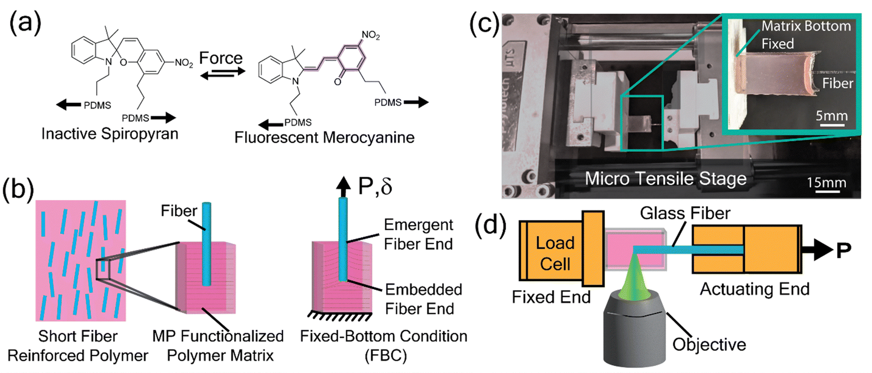 | ||
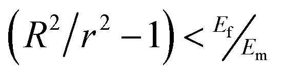
| Fig. 1 Single fiber pull-out sample preparation and experimental setup. (a) Molecular isomerization of MP from spiropyran to fluorescent merocyanine upon loading. (b) Schematic of a glass fiber embedded in a PDMS elastomer matrix with SP mechanophores; loading direction and fixed bottom condition are indicated. (c) Experimental setup for the pull-out test, with the sample secured at the fixed end and the fiber pulled from the actuating end. (d) Confocal microscope setup focused on the fiber end to visualize stress localization via mechanophore fluorescence. | ||
The use of mechanophores in SFRCs offers several significant benefits. Mechanophores can detect stress concentrations at the fiber/matrix interface before macroscopic damage occurs, enabling preventative maintenance and reducing the risk of catastrophic failure.60–64 Early failure detection is crucial for maintaining the structural integrity of composite materials in critical applications. Additionally, the color change in mechanophores provides immediate feedback on the stress state of the composite, allowing for continuous monitoring of the material's load distribution.59 This real-time monitoring capability is particularly valuable in applications where safety and reliability are paramount. Furthermore, by pinpointing areas of high stress concentrations, mechanophores help identify critical regions that require reinforcement or design modification.65,66 This localized stress information is essential for optimizing composite design and improving overall mechanical performance. In this work, we aim to quantify the localized stress at the end of a reinforcing fiber embedded in the matrix of a short fiber-reinforced polymer composite by examining mechanophore activation intensity during a single fiber pull-out test. We focus on the impact of varying fiber end geometries by investigating four different shapes—three axisymmetric and one asymmetric. Utilizing in situ fiber pull-out testing combined with confocal microscopy, we analyze the mechanophore activation intensity arising from stress induced by each fiber end shape. We further model each of the experiments using finite element analysis to corroborate the experimentally measured stresses that we observe. This approach allows us to accurately quantify the localized stress at the fiber ends and compare the results across different geometries. Our comprehensive analysis addresses the critical issue of stress concentrations at fiber ends in SFRCs, essential for preventing composite failure. By investigating different fiber end geometries, we provide precise stress quantification and real-time visualization using mechanophore activation and advanced microscopy. Our experiments demonstrate the detection of localized stresses, facilitating improved design and performance optimization of composites. Our findings provide insights into stress management strategies, essential for developing more durable and high-performance SFRCs.
2. Materials and methods
The experimental setup involved embedding SP mechanophores into the polymer matrix of a single fiber pull-out test specimen. The fiber was then subjected to tensile loading as it was “pulled-out” of the matrix while the activation of the mechanophores was monitored using confocal microscopy. The intensity of the fluorescent signal at the fiber end during pull-out was recorded and analyzed to determine the stress distribution within the composite. By comparing these intensity data with finite element simulations, we established a direct correlation between mechanophore activation and stress levels around each fiber end.2.1. Matrix and fiber materials
To visualize localized stresses in the matrix near the fiber end during pull-out, an elastomeric matrix and glass fiber were selected. For the matrix, we used polydimethylsiloxane (PDMS) elastomer (Sylgard 184 Silicone, Dow), where the base and curing agent were mixed in a 10![[thin space (1/6-em)]](https://www.rsc.org/images/entities/char_2009.gif) :1 ratio by mass. PDMS offers advantages over typical matrix materials, such as its high flexibility and transparency, which make it especially useful in applications requiring highly deformable materials. PDMS's low Young's modulus and high extensibility allow it to undergo large deformations without failure, unlike more rigid matrix materials, making it ideal for real-time stress sensing where large strain is critical.67 Moreover, its transparency supports optical-based mechanophore activation, facilitating visualization of stress distribution. By selecting PDMS as the matrix material in this study, we leveraged its elastic and optical properties to achieve non-invasive stress visualization that would be challenging with more rigid composites.
:1 ratio by mass. PDMS offers advantages over typical matrix materials, such as its high flexibility and transparency, which make it especially useful in applications requiring highly deformable materials. PDMS's low Young's modulus and high extensibility allow it to undergo large deformations without failure, unlike more rigid matrix materials, making it ideal for real-time stress sensing where large strain is critical.67 Moreover, its transparency supports optical-based mechanophore activation, facilitating visualization of stress distribution. By selecting PDMS as the matrix material in this study, we leveraged its elastic and optical properties to achieve non-invasive stress visualization that would be challenging with more rigid composites.
To functionalize the matrix, we added nitro-spiropyran (SPN) mechanophore at a concentration of 0.6 wt%. The activation mechanism of SPNs embedded in PDMS has been extensively studied previously.49,68,69 SPN mechanophores were synthesized following the established protocols.59 At this concentration, there were approximately 6.6 × 10⁶ SPN molecules per μm3, with an average spacing of 6.6 nm between molecules. To enhance SPN solubility in the uncured matrix, we adopted a two-step mixing procedure. The mechanophore was first dissolved in xylenes (99%, ACS Reagent, Acros Organics) at a concentration of 0.05 g mL−1 before being added to the PDMS elastomer base. This mixture was then vortex-mixed (LP Vortex Mixer, Thermo Scientific) for 60 s to ensure homogeneity. Subsequently, the curing agent was added, and the mixture was vortex-mixed for an additional 60 s. Finally, the uncured PDMS mixture was placed under vacuum for 15–20 min to remove entrapped air bubbles before casting.
For the fibers, we used commercially available unsized glass fiber (Hampton Research - HR8-030) with an average diameter of 300 ± 2 μm. To form the cone and sharp fiber ends, we polished the glass fibers on fine grit (2500 grit) papers, allowing for controlled shaping through grinding. For the round tip, we used a melting technique, heating the fiber end until it formed a smooth, rounded shape. These methods allowed precise control over the geometry of each fiber end for consistent comparison across shapes. The glass fibers were then thoroughly cleaned using acetone and deionized water to ensure a clean surface for all experiments.
2.2. Single fiber pull-out sample preparation
To effectively visualize localized stresses at the embedded fiber end, it was essential to prepare the samples so that stress localization would initiate at the embedded end rather than the emergent end at the free silicone surface. This consideration was based on extensive prior research into the failure mechanisms observed in single fiber pull-out tests.18,70,71Two distinct loading configurations can be employed in pull-out tests: the restrained-top condition and the fixed-bottom condition (FBC) which is highlighted in Fig. 1(a). These two conditions are also known as freely and fully supported conditions, respectively. These configurations influence the stress distribution within the specimen during testing, thereby affecting the resulting failure behaviors. Stress concentrations along the loaded fiber's length can cause debonding at either the loaded or embedded fiber end. In the FBC, the load is applied by pulling the free end of the fiber while the bottom of the matrix, where the fiber is embedded, is held fixed. This setup leads to a localized stress concentration in the matrix around the fiber's embedded end. Stress analyses conducted by Leung and Li for FBC provided a criterion for predicting the debonding location by comparing the stresses at both ends.71 Their results indicated that embedded end debonding is likely when:
 | (1) |
To prepare the single fiber pull-out samples with FBC, a glass mold with dimensions of 7 mm × 7 mm × 14 mm was constructed. Fibers were positioned in the center of the mold, held vertically with a 7 mm clearance from the bottom, ensuring an embedded length of 7 mm within the polymer matrix. SPN-functionalized PDMS was then carefully poured into the mold to avoid fiber misalignment or entrapped air bubbles. Once the mold was filled, it was placed in a vacuum oven at 380 mmHg and cured at 70 °C for 24 h. After curing, the single fiber pull-out test specimens (as shown in the inset in Fig. 1(b)), were removed from the mold.
2.3. In situ fiber pull-out testing
We employed an in situ fiber pull-out testing approach that combined a micromechanical load frame with a laser scanning confocal microscope. This setup enabled the real-time quantitative visualization of the stress distribution around embedded fiber ends while measuring load and displacement of the fiber during pull-out.The composite samples were secured to the load frame (μTS, Psylotech) using custom 3D-printed grips (Form3, Form Labs). The bottom side of the matrix was affixed to the stationary grip of the load frame, while the exposed fiber end was attached to the movable grip of the frame. The mechanical testing configuration shown in Fig. 1(b), enables precise observation of the matrix near the fiber end during each experiment. Pull-out experiments were conducted at a displacement rate of 10 μm s−1, corresponding to a strain rate of 0.001 s−1, until failure.
During each fiber pull-out experiment, the SPN activation intensity was recorded using a laser scanning confocal microscope (SP8, Leica Microsystems). We utilized an air objective lens (5X, NA = 0.15) with a long working distance (WD = 12 mm). The activated SPN molecules in the matrix were excited at λ = 552 nm with a 1 mW output power, selected to match the absorbance peak of SPN in PDMS. Emissions from the activated SPN were captured by a photomultiplier tube (PMT) set to a gain of 600 mV, with an emission range spanning 600 nm to 725 nm.49,72
Images sequences (581 μm by 581 μm) with an approximate pixel size of 1.14 μm by 1.14 μm were taken at the sample's mid-plane to provide a detailed view of stress localization and debonding events at the fiber equator. For all experiments, the pinhole size was set to 1 Airy Unit, providing a depth of field of 7.23 μm. Images were acquired at intervals of 1.5 s. Manual adjustments of the focal plane were performed at each mechanical displacement step to maintain a precise focus on the fiber's mid-plane. By ensuring the focal plane remained aligned with the fiber's mid-plane, we could consistently capture images of the stress distribution in the same location within the sample volume.
3. Results and discussions
Using mechanophore activation intensity as a surrogate for magnitude of stress, this study provided a detailed visualization of localized stress zones within the matrix at the fiber ends in short fiber-reinforced composites. We examined four different fiber end shapes: three axisymmetric (flat, cone, and round ends) and one non-axisymmetric (a sharp end shape with a complex geometry designed to mimic real-world applications). By analyzing the MP activation intensity for each shape, we quantified the localized stress at the fiber ends and compared the results across different geometries. This comprehensive analysis allowed us to identify the impact of localized stresses and quantify them with high spatial sensitivity.3.1. Analyzing the pull-out test results
A customized in situ pull-out testing setup was employed, integrating a micromechanical load frame with a laser scanning confocal microscope. As the fiber was pulled out from the matrix, stress distribution was tracked by monitoring changes in MP activation intensity around the fiber tip.The load versus displacement curves of representative fiber pull-out experiments shown in Fig. 2 offer a comprehensive view of the mechanical response of the four fiber end geometries tested here: round, sharp, cone, and flat. At small strains, an initial linear increase in force was observed for all fiber end geometries. During this phase, the material exhibits elastic behavior, with the embedded fibers resisting the load without permanent deformation and the interface between fiber and matrix remaining intact. Just prior to detachment at the fiber end, the highest peak force value was observed for the round end and the lowest for the flat end fiber. Following this peak force, additional displacement leads to a debonding event that results in a large decrease in force. Frictional sliding then occurs as the fiber is pulled out at a relatively low, gradually decreasing load proportional to the decreasing embedded length of the fiber.
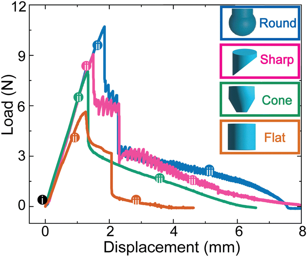 | ||
| Fig. 2 Pull-out force and localized stresses for various fiber end geometries. Representative load vs. displacement curves are shown for round, sharp, cone and flat fiber tips. Tip shapes are illustrated in the legend, with colors corresponding to each curve. Numbered dots (i, ii, iii) indicate different pull-out test regimes. | ||
The maximum load that could be applied to each fiber before the onset of cavitation or interfacial failure varies with end geometry. As the load increases to the peak force, stress concentrations form (observed through fluorescence intensity of the activated SPN) and increase in magnitude at the fiber tips. This stress localization leads to initiation of the debonding process between the fiber and matrix near the fiber tip as highlighted in Fig. 3. This transition from predominantly elastic behavior to debonding failure is marked by a sharp decline in the load for each configuration.
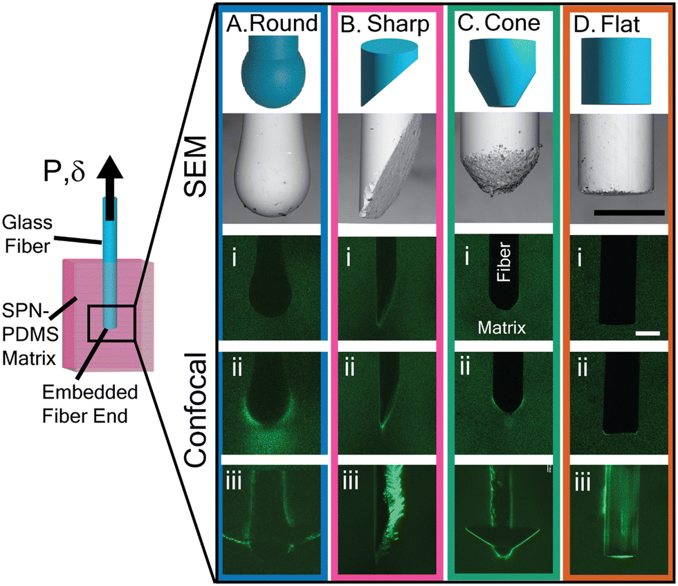 | ||
| Fig. 3 Fiber end geometries (flat, cone, sharp, round) imaged before and during pull-out testing. Rows (i, ii, iii) correspond to load and displacement points as indicated on the curves in Fig. 2: (i) no strain, (ii) linear elastic loading regime, prior to peak load and onset of fiber-matrix debonding, and (iii) fiber sliding post-debonding. Scale bars on panel-A Flat, SEM and confocal images represent 300 μm and apply to all images. | ||
Following the initiation of failure at the maximum load, the load varies significantly between configurations, reflecting different sliding and failure mechanisms that are commonly described as “stick-slip” and “full sliding” friction mechanisms. The stick-slip behavior is observed after debonding, particularly in the sharp and round fiber ends. This behavior is characterized by intermittent contact and localized reattachment as the fibers are pulled through the matrix, resulting in oscillations in the load-displacement curve. In contrast, a full slip or continuous sliding mechanism is seen in the flat and cone end configurations, reflecting a steady decrease in load due to uninterrupted, frictional sliding with minimal load fluctuations.
The points labeled (i), (ii), and (iii) on each curve (Fig. 2) denote various experimental regimes during the pull-out experiments. The corresponding mechanophore activation during these experiments at the variously shaped fiber ends are shown in the fluorescence intensity micrographs (Fig. 3). For each geometry, (i) indicates the start of the experiment, (ii) denotes the elastic deformation regime before debonding, and (iii) indicates the friction resulting from the fiber sliding through the shaft of the matrix. These distinct behaviors and key events across different configurations highlight the fiber end geometry effects on the failure process.
3.2. Evaluating MP activation intensities
The activation intensities of MPs enable direct observation of the stress localization and distribution within the matrix of a loaded composite sample. During fiber pull-out, strain-induced deformation triggers molecular rearrangements in the MPs, which are covalently attached to the polymer matrix. The uniformly distributed MPs are activated in proportion to the local stresses within the matrix. As stress in the matrix increases, more MPs activate, resulting in increased fluorescence intensity. To investigate the stress localization, fluorescence intensities were compared at different global strains. A 100 μm wide line scan of the fluorescence intensity was taken, starting from the surface of the fiber end and extending into the matrix away from the fiber at a 180° angle relative to the fiber loading direction as shown in the insert in Fig. 4a.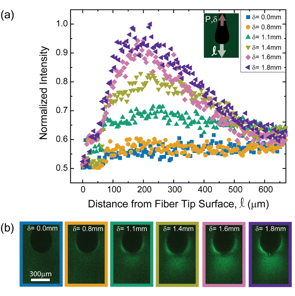 | ||
| Fig. 4 (a) Mechanophore activation intensity as a function of distance from the round fiber tip for various pull-out displacements. Inset shows intensity scan direction relative to fiber loading direction. (b) Confocal fluorescence images of a round fiber end during pull-out, with displacement labeled atop each image. Scale bar in the left image applies to all images. | ||
The normalized fluorescence activation intensity of SPN as a function of distance from the fiber tip surface ![[small script l]](https://www.rsc.org/images/entities/i_char_e146.gif) is shown in Fig. 4(a) for various fiber pull-out displacements δ. Higher activation intensities were observed in the matrix at larger displacements around the fiber end due to the normal and shear stresses accumulating in the matrix during fiber pull-out. These intensity changes provide insight into how loading affects the stress distribution near the fiber-matrix interface.
is shown in Fig. 4(a) for various fiber pull-out displacements δ. Higher activation intensities were observed in the matrix at larger displacements around the fiber end due to the normal and shear stresses accumulating in the matrix during fiber pull-out. These intensity changes provide insight into how loading affects the stress distribution near the fiber-matrix interface.
The round fiber end significantly impacts stress distribution and MP activation, exhibiting distinct mechanical behavior compared to other end geometries. When pulled, the surrounding matrix deforms, creating a more gradual and diffuse stress distribution, affecting the composite material's overall mechanical behavior. As the distance from the fiber tip increases, normalized intensity rises, peaking at varying distances depending on the pull-out displacement. A small region (approximately 50 μm) at the round fiber surface showed no MP activation as shown in Fig. 4b. This depletion zone appears near the surface of the fiber tip where overlapping tensile and shear stresses reduce the overall stress, leading to less mechanophore activation. In finite element modeling, hydrostatic stress models overestimate stress near these interfaces, missing the interaction between different stress types. The maximum principal stress can capture the actual stress distribution and match experimental observations, as it correlates more accurately with the observed mechanophore activation patterns in the matrix.
As displacement increases, stress concentrates in specific regions, leading to a higher peak intensity as the stress is redistributed in the fiber-matrix. The fluorescence intensity peaks at increasing fiber displacements reflect alignment of polymer chains within small, highly stretched regions of the matrix, causing more SPN molecules to activate there.
The stress decay pattern is also influenced by fiber geometry. The rounded tip's curvature allows a more gradual stress transfer into the matrix, resulting in a broader stress distribution and reducing localized, high intensity stress concentrations.
3.3. Calibration of fluorescence intensity (I) to stress (σ)
Finite element analysis was carried out to calculate the maximum principal stresses σ (Abaqus/CAE 2021) by modeling the mechanical behavior of each pull-out experiment. These analyses followed similar computations published previously.58,59 The model utilized a 2D cross-sectional representation of one half of the sample to simplify the analysis. The SPN/PDMS matrix was modeled using four-node hybrid cohesive plane strain elements with reduced integration. Experimental data fitting yielded a second-order Ogden hyperelastic model for the matrix, characterized by a Poisson's ratio (ν) of 0.495, and the Ogden constants μ1 = 0.4095 MPa, μ2 = 0.0243 MPa, α1 = 1.11, and α2 = −6.19. The glass fiber was modeled as an elastic material with a Young's modulus (E) of 70 GPa and a Poisson's ratio (ν) of 0.3. The fiber-matrix interface was treated as non-deformable by tying the elements together along the fiber surface. Symmetric boundary conditions were applied along the interior faces of the quadrant to reduce computational complexity. A displacement boundary condition was applied to the top surface of the model, set to 7 mm to correspond with the maximum embedded fiber length. Detailed discussions of the FEA model and its implementation are provided in the ESI.† The boundary conditions, mesh specifications, and model dimensions have explicitly been described in the ESI.† We have also provided detailed figures illustrating the model's meshing approach, the application of boundary conditions, and a schematic of the 2D axisymmetric FEA model in ESI† (Section 2), to support reproducibility and clarity in our FEA methodology.The plot in Fig. 5 compares the normalized fluorescent activation intensities (I) from in situ single fiber pull-out testing of a round-ended fiber with the maximum principal stresses (σ) derived from the FEA model. This data is presented for three different angular orientations: 0°, 45°, and 90°.
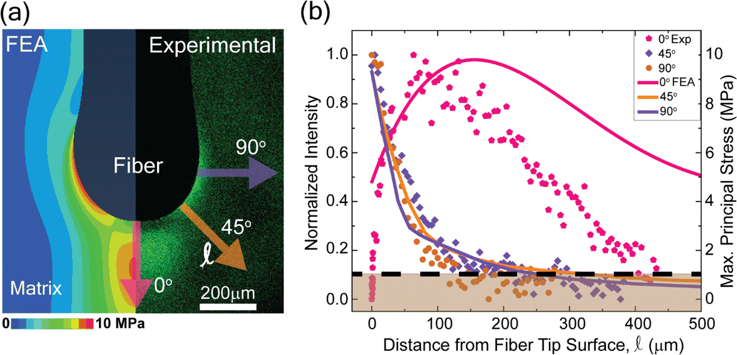 | ||
| Fig. 5 Correlation between finite element analysis (FEA) and experimental fluorescence intensities. (a) FEA-calculated maximum principal stress vs. experimental fluorescence intensities at different orientations from the fiber tip. (b) Normalized intensity vs. distance from the fiber tip, with an MP activation threshold at ∼1.0 MPa indicated by the dashed line. Shaded region highlights data below the threshold. Points are experimental intensity measurements (left y-axis), and solid lines are FEA-calculated stress values (right y-axis). | ||
The 45° and 90° orientation data show a gradual decrease in both normalized intensity and maximum principal stress reflecting the material's anisotropic properties. Along 0° orientation, the experimental and FEA data both exhibits a decrease in material response with distance. While the FEA model provides an estimate of stress distribution, the observed differences between FEA-predicted stress and experimental mechanophore intensity can be attributed to inherent model assumptions and the specific characteristics of mechanophore response. The FEA assumes uniform material properties and ideal boundary conditions, which may lead to higher stress values calculated near the fiber-matrix interface, especially where complex, non-linear behaviors occur. Importantly, the FEA model accounts only for elastic deformation and does not capture potential molecular-scale damage or chain scission within the polymer matrix network that is almost certainly occurring experimentally. Such network damage results in more distributed stress and lower observed intensity values in our real system than those calculated with FEA.
Additionally, mechanophore fluorescence intensity can be influenced by factors beyond direct stress magnitude, such as local environmental conditions, photo-reversion effects, and fluorescence saturation at high-stress levels. These factors may contribute to a non-linear intensity to stress response and a plateau effect in mechanophore activation, creating discrepancies between experimental measurements and FEA predictions. Collectively, these considerations emphasize the need to interpret FEA results with an understanding of the limitations of mechanophore fluorescence response and the complexities of real experimental conditions.
To describe this relationship, we fit an exponential decay model to the data. By deriving a single equation that fits both the normalized intensity and maximum principal stress data, we establish a direct relationship between these parameters and the distance from the fiber tip. Eqn (2) provides a direct relationship between stress, intensity, and distance from fiber tip surface. This equation is derived from the empirical observation that both stress (σ) and mechanophore fluorescence intensity (I) decrease exponentially with distance from the point of maximum stress concentration. Previous studies have shown similar exponential decay behaviors in mechanophore-based stress reporting, particularly near localized stress fields, supporting the applicability of this form for mapping stress fields from fluorescence data.59,73 The calibration using the round fiber geometry, with its consistent stress gradient and minimal stress concentration anomalies, serves as a reliable basis for establishing this relationship.
 | (2) |
= 0; n is the ratio of decay constants (m/k). Decay constants k and m describe the rate at which normalized intensity I() and maximum principal stress σ() decrease with distance from the fiber tip. These constants describe how quickly the normalized intensity decreases with distance. A larger k and m indicate a faster decay. The ratio of decay constants n provides insight into the relative decay rates of intensity and stress. If n > 1, stress decays faster than intensity, and if n < 1, intensity decays faster than stress. For the images acquired on our confocal with the machine settings listed in the Materials and methods section, n ≈ 2.5 for a PDMS matrix with 0.6 wt% SPN. This empirical relationship, represented by eqn (2), serves as a first-order approximation for estimating stress from fluorescence intensity, allowing for the visualization of general stress trends across different fiber geometries. The calibration aligns well with FEA predictions for simpler shapes such as the round geometry. However, deviations observed in Fig. S6 (ESI†) for more complex geometries, including the flat, cone, and sharp fiber ends, can be attributed to geometry-specific stress localizations and surface roughness effects at the fiber-matrix interface. These factors are not fully captured by a calibration curve derived solely from the round-end geometry, which exhibits a monotonic stress gradient. Such variations emphasize that while eqn (2) is a useful tool for general stress mapping, it is not intended to provide precise stress distributions for geometries with complex boundary conditions.
Calibrating mechanophore intensity to maximum principal stress was achieved using an established protocol57–59 that links the intensity of MP activation from experiments to the stress predicted by FEA for similar material systems. We performed line scans at a 0° angle relative to the loading direction from the fiber end into the matrix. These experimental intensities were then correlated with stress values from FEA at different displacements. This correlation approach allowed us to create calibrated images of maximum principal stress in the matrix. The method was initially calibrated using the round-end fiber, but it also applies to cone and flat-end geometries, and extends to sharp ends, due to the consistent MP/matrix materials and imaging protocols. The calibrated images, shown in Fig. 6, align well with the FEA models (Fig. S6, ESI†), highlighting the stress fields at the fiber end.
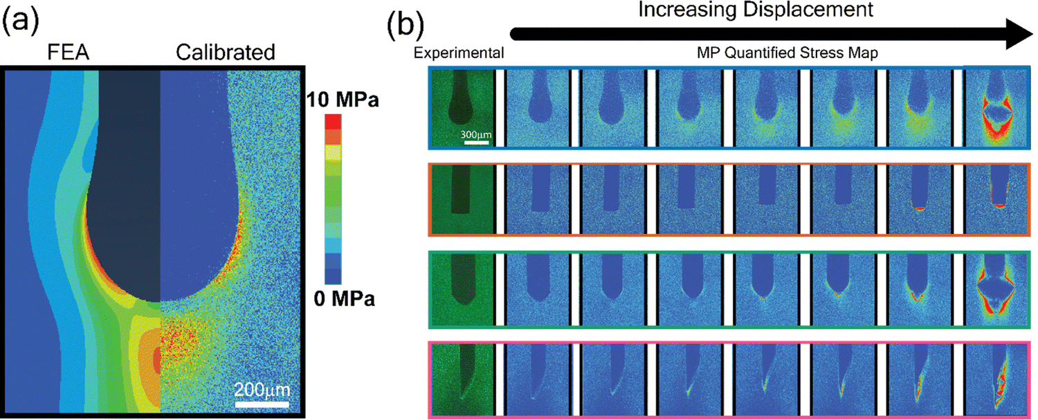 | ||
| Fig. 6 Quantified stress map using calibration based on MP activation intensity and FEA-derived maximum principal stresses for various fiber end geometries. (a) Side-by-side FEA and calibrated images show stress distribution from experimental intensity data. (b) Calibrated stress maps for different fiber end shapes at various displacement levels. Scale bar in the top left image of (b) applies to all images. | ||
Detecting small local stress concentrations and gradients is critical for evaluating matrix stresses in loaded composites. We observed a potential combined impact of cavitation and surface roughness on stress distribution for the irregular fiber tips (cone, sharp), leading to distinct stress responses observed at higher loads. The irregular fiber end shapes can cause more acute stress concentrations, as demonstrated by the various geometries. Applying the calibration shows high stress concentrations at specific regions, which act as nucleation sites for fractures, ultimately leading to composite failure as cracks propagate from these points.
While spiropyran is a reversible mechanophore capable of activation and reversion under cyclic loading, the samples in this study were tested to failure, limiting the experiments to single-use activation. The mechanophore-based stress sensing method can be adapted for various other fiber-matrix systems by tailoring the mechanophore properties and interface bonding. For example, in high-modulus matrices like epoxy, higher activation-threshold mechanophores prevent premature signaling. Thermoplastic matrices, on the other hand, benefit from thermally stable, reversible mechanophores for applications with cyclic loading. Additionally, carbon or glass fibers require mechanophores to be durable under high load conditions, whereas natural fibers in bio-composites may need environmentally resilient mechanophores to handle moisture and UV exposure. These adjustments allow mechanophore as a tool to support diverse composite applications effectively. Future work will focus on refining calibration methods to account for complex fiber geometries and variable surface effects, aiming to improve the fidelity of stress-intensity mapping across diverse configurations.
4. Conclusions
This study examines the fiber end geometry effect on stress distribution in short fiber-reinforced polymer composites. We integrated mechanophore-based stress sensing with finite element analysis to quantitatively assess localized stresses that develop in the matrix of SFRCs upon mechanical loading in real time.By activating mechanophores embedded with the SPN functionalized PDMS matrix, we visualized and quantified localized stresses at fiber ends in SFRCs. Different fiber end shapes—flat, cone, round, and sharp—were tested under a single fiber pull-out test to analyze their effects on stress distribution and failure initiation within the polymer matrix. Results show that round fiber ends promote effective stress distribution and gradual load transfer. This geometry creates a more distributed stress field, enhancing the visualization of stress transfer mechanisms at the microscale. Sharp fiber ends demonstrate different post-peak failure mechanisms.
Normalized intensity values of MP activation showed that higher pulling distances induced greater stress concentrations further from the fiber tip, effectively activating the MPs. The geometrical effect of round-ended fibers significantly alters stress localization and dissipation. This geometry also influenced the stress decay pattern by promoting a smoother transfer of stress into the matrix material, leading to a broader and more diffuse stress distribution. The curvature of the round fiber end causes a more gradual increase in stress. This smooth stress transfer and distribution prevent premature localized failure, as seen in sharply pointed fibers where stress intensely localizes at the tip.
The intensity to stress calibration done for the round-end geometry matched the specific FEA results for other fiber end shapes, extending the methodology to complex non-axisymmetric geometries like the sharp-end fiber. This versatility enables precise stress mapping in intricate fiber shapes, providing essential insights for optimizing composite material design and performance.
In conclusion, we demonstrated a comprehensive analysis of stress distribution in the polymer matrix of SFRCs with varying fiber end geometries. Mechanophore activation intensity serves as a visualization tool for stress concentration zones, enhancing our ability to map microscale stress distribution accurately.
Future research on the long-term behavior of mechanophore-embedded composites under cyclic loading and various environmental conditions will provide valuable insights into their durability and performance. Studies may also adapt mechanophore-based sensing to glassy matrices, using findings from similar systems to evaluate potential changes in stress transfer and activation mechanisms. Additionally, the development of advanced mechanophores with greater sensitivity and specificity will enhance the resolution and accuracy of stress mapping, enabling more sophisticated and reliable composite materials across a range of industries. This approach holds significant promise for advancing composite material design, leading to innovations in structural applications where precise stress management is essential.
Data availability
The data supporting this article have been included as part of the ESI.†Conflicts of interest
There are no conflicts to declare.Acknowledgements
N. H. and C. D. acknowledge support from the NSF-CMMI CAREER (Grant #2045908). H-C. C. and C-C. C. acknowledge support from the Young Scholar Fellowship Program by National Science and Technology (Grant 111-2636-E-A49-015 and 111-2634-FA49-007)) and the Center for Emergent Functional Matter Science of National Yang Ming Chiao Tung University from The Featured Areas Research Center Program within the framework of the Higher Education Sprout Project by the Ministry of Education (MOE) in Taiwan.References
- L. Jiang, Y. Zhou and F. Jin, Design of short fiber-reinforced thermoplastic composites: A review, Polym. Compos., 2022, 43, 4835–4847, DOI:10.1002/pc.26817
.
- S. Adil and I. Lazoglu, A review on additive manufacturing of carbon fiber-reinforced polymers: Current methods, materials, mechanical properties, applications and challenges, J. Appl. Polym. Sci., 2023, 140, 1–28, DOI:10.1002/app.53476
- H. Rolland, N. Saintier and G. Robert, Damage mechanisms in short glass fibre reinforced thermoplastic during in situ microtomography tensile tests, Composites, Part B, 2016, 90, 365–377, DOI:10.1016/j.compositesb.2015.12.021
- H. Rolland, N. Saintier, P. Wilson, J. Merzeau and G. Robert,
In situ X-ray tomography investigation on damage mechanisms in short glass fibre reinforced thermoplastics: Effects of fibre orientation and relative humidity, Composites, Part B, 2017, 109, 170–186, DOI:10.1016/j.compositesb.2016.10.043
-
M. R. Piggott, Load-Bearing Fibre Composites, Elsevier, 1980 DOI:10.1016/C2013-0-05885-9
- Y. T. Zhu, J. A. Valdez, N. Shi, M. L. Lovato, M. G. Stout, S. J. Zhou, D. P. Butt, W. R. Blumenthal and T. C. Lowe, A composite reinforced with bone-shaped short fibers, Scr. Mater., 1998, 38, 1321–1325, DOI:10.1016/S1359-6462(98)00063-3
- I. J. Beyerlein, Y. T. Zhu and S. Mahesh, On the influence of fiber shape in bone-shaped short-fiber composites, Compos. Sci. Technol., 2001, 61, 1341–1357, DOI:10.1016/S0266-3538(01)00029-X
- Y. Zhou, C. Li and J. J. Mason, Fiber-end deformation effects in enlarged-end, fiber-reinforced composites, Eng. Fract. Mech., 2005, 72, 1980–1992, DOI:10.1016/j.engfracmech.2004.10.017
- Y. T. Zhu, J. A. Valdez, I. J. Beyerlein, S. J. Zhou, C. Liu, M. G. Stout, D. P. Butt and T. C. Lowe, Mechanical properties of bone-shaped-short-fiber reinforced composites, Acta Mater., 1999, 47, 1767–1781, DOI:10.1016/S1359-6454(99)00071-3
- Y. T. Zhu and I. J. Beyerlein, Bone-shaped short fiber composites—an overview, Mater. Sci. Eng.: A, 2002, 326, 208–227, DOI:10.1016/S0921-5093(01)01486-1
- R. C. Wetherhold and F. K. Lee, Shaped ductile fibers to improve the toughness of epoxy-matrix composites, Compos. Sci. Technol., 2001, 61, 517–530, DOI:10.1016/S0266-3538(00)00217-7
- N. Sato, T. Kurauchi, S. Sato and O. Kamigaito, Mechanism of fracture of short glass fibre-reinforced polyamide thermoplastic, J. Mater. Sci., 1984, 19, 1145–1152, DOI:10.1007/BF01120023
- N. Sato, T. Kurauchi, S. Sato and O. Kamigaito, Microfailure behaviour of randomly dispersed short fibre reinforced thermoplastic composites obtained by direct SEM observation, J. Mater. Sci., 1991, 26, 3891–3898, DOI:10.1007/BF01184987
- J. A. Nairn, C.-H. Liu, D.-A. Mendels and S. Zhandarov, Fracture Mechanics Analysis of the Single-Fiber Pull-Out Test and the Microbond Test Including The Effects of Friction and Thermal Stresses, Proceeding 16th Annu. Technol. Conf. Am. Soc. Compos., 2001 Search PubMed.
- D. Tripathi and F. R. Jones, Single fibre fragmentation test for assessing adhesion in fibre reinforced composites, J. Mater. Sci., 1998, 33, 1–16, DOI:10.1023/A:1004351606897
- M. R. Piggott, Failure processes in the fibre-polymer interphase, Compos. Sci. Technol., 1991, 42, 57–76, DOI:10.1016/0266-3538(91)90012-E
- A. N. Gent and G. L. Liu, Pull-out and fragmentation in model fibre composites, J. Mater. Sci., 1991, 26, 2467–2476, DOI:10.1007/BF01130197
- C. Wang, Fracture mechanics of single-fibre pull-out test, J. Mater. Sci., 1997, 32, 483–490, DOI:10.1023/A:1018534323464
- F. Teklal, A. Djebbar, S. Allaoui, G. Hivet, Y. Joliff and B. Kacimi, A review of analytical models to describe pull-out behavior –
Fiber/matrix adhesion, Compos. Struct., 2018, 201, 791–815, DOI:10.1016/j.compstruct.2018.06.091
- M. R. Piggott, The single-fibre pull-out method: its advantages, interpretation and experimental realization, Compos. Interfaces, 1993, 1, 211–223, DOI:10.1163/156855493X00086
- F. M. Yannick Blandin and Daniel Sainte-Foi, Method and apparatus for making fibres, Composites, 1992, 3, 282–283, DOI:10.1016/0010-4361(72)90201-7
- T. F. MacLaughlin, Effect of fiber geometry on stress in fiber-reinforced composite materials - Maximum shear stresses were obtained photoelastically in the matrices of fiber-reinforced material models, constructed by casting a birefringent epoxy resin around variously arra, Exp. Mech., 1966, 6, 481–492, DOI:10.1007/BF02326519
- W. R. Tyson and G. J. Davies, A photoelastic study of the shear stresses associated with the transfer of stress during fibre reinforcement, Br. J. Appl. Phys., 1965, 16, 199, DOI:10.1088/0508-3443/16/2/313
- B. D. Agarwal and R. K. Bansal, Plastic analysis of fibre interactions in discontinuous fibre composites, Fibre Sci. Technol., 1977, 10, 281–297, DOI:10.1016/0015-0568(77)90005-7
- A. S. Carrara and F. J. Mcgarry, Matrix and Interface Stresses in a Discontinuous Fiber Composite Model, J. Compos. Mater., 1968, 2, 222–243, DOI:10.1177/002199836800200208
- Y. T. Zhu, I. J. Beyerlein, J. A. Valdez and T. C. Lowe, Fracture toughness of a composite reinforced with bone-shaped short fibers, Mater. Sci. Eng., A, 2001, 317, 93–100, DOI:10.1016/S0921-5093(01)01166-2
- M. Shuster, D. Sherman, A. Siegmann, M. Narkis, C. M. Jennewein and P. Eyerer, Stress distribution in and around a spherically ended fiber embedded in a polymer matrix, Polym. Compos., 1996, 17, 568–577, DOI:10.1002/pc.10647
- H. Jiang, J. A. Valdez, Y. T. Zhu, I. J. Beyerlein and T. C. Lowe, The strength and toughness of cement reinforced with bone-shaped steel wires, Compos. Sci. Technol., 2000, 60, 1753–1761, DOI:10.1016/S0266-3538(00)00055-5
- Y. L. Dong and B. Pan, A Review of Speckle Pattern Fabrication and Assessment for Digital Image Correlation, Exp. Mech., 2017, 578, 1161–1181, DOI:10.1007/S11340-017-0283-1
- J. M. Vázquez-Rodríguez, E. A. Flores-Johnson, P. J. Herrera-Franco and P. I. Gonzalez-Chi, Photoelastic and numerical analyses of the stress distribution around a fiber in a pull-out test for a thermoplastic fiber/epoxy resin composite, Polym. Compos., 2018, 39, E2397–E2406, DOI:10.1002/pc.24709
- C. Tuloup, W. Harizi, Z. Aboura, Y. Meyer, K. Khellil and R. Lachat, On the use of in-situ piezoelectric sensors for the manufacturing and structural health monitoring of polymer-matrix composites: A literature review, 2019.
- R. Soman, J. Wee and K. Peters, Optical fiber sensors for ultrasonic structural health monitoring: A review, Sensors, 2021, 21, 1–34, DOI:10.3390/s21217345
- B. Wang, S. Zhong, T. L. Lee, K. S. Fancey and J. Mi, Non-destructive testing and evaluation of composite materials/structures: A state-of-the-art review, 2020 DOI:10.1177/1687814020913761.
- H. Murayama, D. Wada and H. Igawa, Structural health monitoring by using fiber-optic distributed strain sensors with high spatial resolution, Photonic Sens., 2013, 3, 355–376, DOI:10.1007/s13320-013-0140-5
- B. A. Beiermann, D. A. Davis, S. L. B. Kramer, J. S. Moore, N. R. Sottos and S. R. White, Environmental effects on mechanochemical activation of spiropyran in linear PMMA, J. Mater. Chem., 2011, 21, 8443–8447, 10.1039/C0JM03967E
- C. S. Davis, M. L. Rencheck, J. W. Woodcock, R. Beams, M. Wang, S. Stranick, A. M. Förster and J. W. Gilman, Activation of Mechanophores in a Thermoset Matrix by Instrumented Scratch, ACS Appl. Mater. Interfaces, 2021, 13, 55498–55506, DOI:10.1021/acsami.1c15004
- J. Li, T. Shiraki, B. Hu, R. A. E. Wright, B. Zhao and J. S. Moore, Mechanophore Activation at Heterointerfaces, J. Am. Chem. Soc., 2014, 136, 15925–15928, DOI:10.1021/ja509949d
- T. A. Kim, C. Lamuta, H. Kim, C. Leal and N. R. Sottos, Interfacial Force-Focusing Effect in Mechanophore-Linked Nanocomposites, Adv. Sci., 2020, 7(7), 1903464, DOI:10.1002/ADVS.201903464
- J. A. Gohl, N. Haque and C. S. Davis, Sensing stresses and damage in adhesive bonds using mechanophores, Adv. Struct. Adhes. Bonding, 2023, 1123–1139, DOI:10.1016/B978-0-323-91214-3.00019-3
- D. A. Davis, A. Hamilton, J. Yang, L. D. Cremar, D. Van Gough, S. L. Potisek, M. T. Ong, P. V. Braun, T. J. Martínez, S. R. White, J. S. Moore and N. R. Sottos, Force-induced activation of covalent bonds in mechanoresponsive polymeric materials, Nature, 2009, 459, 68–72, DOI:10.1038/nature07970
- F. Verstraeten, R. Göstl and R. P. Sijbesma, Stress-induced colouration and crosslinking of polymeric materials by mechanochemical formation of triphenylimidazolyl radicals, Chem. Commun., 2016, 52, 8608–8611, 10.1039/c6cc04312g
- S. He, M. Stratigaki, S. P. Centeno, A. Dreuw and R. Göstl, Tailoring the Properties of Optical Force Probes for Polymer Mechanochemistry, Chem. – Eur. J., 2021, 27, 15889–15897, DOI:10.1002/CHEM.202102938
- C. Baumann, M. Stratigaki, S. P. Centeno and R. Göstl, Multicolor Mechanofluorophores for the Quantitative Detection of Covalent Bond Scission in Polymers, Angew. Chem., Int. Ed., 2021, 60, 13287–13293, DOI:10.1002/ANIE.202101716
- M. B. Larsen and A. J. Boydston, Flex-activated” mechanophores: Using polymer mechanochemistry to direct bond bending activation, J. Am. Chem. Soc., 2013, 135, 8189–8192, DOI:10.1021/ja403757p
- N. Deneke, M. L. Rencheck and C. S. Davis, An engineer's introduction to mechanophores, Soft Matter, 2020, 16, 6230–6252, 10.1039/d0sm00465k
- Z. Xia, V. D. Alphonse, D. B. Trigg, T. P. Harrigan, J. M. Paulson, Q. T. Luong, E. P. Lloyd, M. H. Barbee and S. L. Craig, Seeing’ strain in soft materials, Molecules, 2019, 24, 542, DOI:10.3390/molecules24030542
- C. K. Lee, B. A. Beiermann, M. N. Silberstein, J. Wang, J. S. Moore, N. R. Sottos and P. V. Braun, Exploiting Force Sensitive Spiropyrans as Molecular Level Probes, Macromolecules, 2013, 46, 3746–3752, DOI:10.1021/ma4005428
- Y. Chen, G. Mellot, D. Van Luijk, C. Creton and R. P. Sijbesma, Mechanochemical tools for polymer materials, Chem. Soc. Rev., 2021, 50, 4100–4140, 10.1039/d0cs00940g
- G. R. Gossweiler, G. B. Hewage, G. Soriano, Q. Wang, G. W. Welshofer, X. Zhao and S. L. Craig, Mechanochemical activation of covalent bonds in polymers with full and repeatable macroscopic shape recovery, ACS Macro Lett., 2014, 3, 216–219, DOI:10.1021/mz500031q
- M. Li, Mechanoresponsive Polymers Based on Spiropyran Mechanophore, PhD Diss, 2017, https://macsphere.mcmaster.ca/handle/11375/22391 Search PubMed.
- M. Li, Q. Zhang, Y. N. Zhou and S. Zhu, Let spiropyran help polymers feel force, Prog. Polym. Sci., 2018, 79, 26–39, DOI:10.1016/j.progpolymsci.2017.11.001
- Y. Chen, C. J. Yeh, Q. Guo, Y. Qi, R. Long and C. Creton, Fast reversible isomerization of merocyanine as a tool to quantify stress history in elastomers, Chem. Sci., 2021, 12, 1693–1701, 10.1039/D0SC06157C
- E. Ducrot, Y. Chen, M. Bulters, R. P. Sijbesma and C. Creton, Toughening elastomers with sacrificial bonds and watching them break, Science, 2014, 344, 186–189, DOI:10.1126/science.1248494
- X. P. Morelle, G. E. Sanoja, S. Castagnet and C. Creton, 3D fluorescent mapping of invisible molecular damage after cavitation in hydrogen exposed elastomers, Soft Matter, 2021, 17, 4266–4274, 10.1039/d1sm00325a
- Y. Chen, G. Sanoja and C. Creton, Mechanochemistry unveils stress transfer during sacrificial bond fracture of tough multiple network elastomers, Chem. Sci., 2021, 12, 11098–11108, 10.1039/D1SC03352B
- Y. Chen, C. J. Yeh, Y. Qi, R. Long and C. Creton, From force-responsive molecules to quantifying and mapping stresses in soft materials, Sci. Adv., 2020, 6, 1–9, DOI:10.1126/sciadv.aaz5093
- M. L. Rencheck, B. T. Mackey, Y. Y. Hu, C. C. Chang, M. D. Sangid and C. S. Davis, Identifying Internal Stresses during Mechanophore Activation, Adv. Eng. Mater., 2021, 2101080, 1–10, DOI:10.1002/adem.202101080
- J. A. Gohl, T. J. Wiley, H.-C. Chang, C. Chang and C. S. Davis, Stress quantification in a composite matrix via mechanophores, Front, Soft Matter, 2023, 3, 1–10, DOI:10.3389/frsfm.2023.1125163
- N. Haque, J. Gohl, C. Chang, H. C. Chang and C. S. Davis, Quantifying Localized Stresses in the Matrix of a Fiber-Reinforced Composite via Mechanophores, Macromol. Chem. Phys., 2023, 224, 2300298, DOI:10.1002/macp.202300298
- M. E. Grady, C. M. Birrenkott, P. A. May, S. R. White, J. S. Moore and N. R. Sottos, Localization of Spiropyran Activation, Langmuir, 2020, 36, 5847–5854, DOI:10.1021/acs.Langmuir.0c00568
- S. Lörcher, T. Winkler, K. Makyła, C. Ouellet-Plamondon, I. Burgert and N. Bruns, Mechanical unfolding of a fluorescent protein enables self-reporting of damage in carbon-fibre-reinforced composites, J. Mater. Chem. A, 2014, 2, 6231–6237, 10.1039/c3ta14803c
- K. Makyła, C. Müller, S. Lörcher, T. Winkler, M. G. Nussbaumer, M. Eder and N. Bruns, Fluorescent protein senses and reports mechanical damage in glass-fiber-reinforced polymer composites, Adv. Mater., 2013, 25, 2701–2706, DOI:10.1002/adma.201205226
- J. P. F. Lagerwall, C. Schütz, M. Salajkova, J. Noh, J. H. Park, G. Scalia and L. Bergström, Cellulose nanocrystal-based materials: From liquid crystal self-assembly and glass formation to multifunctional thin films, NPG Asia Mater., 2014, 6, e80, DOI:10.1038/AM.2013.69
- M. L. Rencheck, M. Korey, X. Zhao, H. Tekinalp and S. Ozcan, Towards the applications of mechanophore incorporated feedstocks for additive manufacturing, Mater. Today Commun., 2023, 34, 105525, DOI:10.1016/J.MTCOMM.2023.105525
- J. W. Woodcock, R. Beams, C. S. Davis, N. Chen, S. J. Stranick, D. U. Shah, F. Vollrath and J. W. Gilman, Observation of Interfacial Damage in a Silk-Epoxy Composite, Using a Simple Mechanoresponsive Fluorescent Probe, Adv. Mater. Interfaces, 2017, 4, 1–5, DOI:10.1002/admi.201601018
- J. W. Woodcock, R. J. Sheridan, R. Beams, S. J. Stranick, W. F. Mitchell, L. C. Brinson, V. Gudapati, D. Hartman, A. Vaidya, J. W. Gilman and G. A. Holmes, Damage sensing using a mechanophore crosslinked epoxy resin in single-fiber composites, Compos. Sci. Technol., 2020, 192, 108074, DOI:10.1016/j.compscitech.2020.108074
- H. Qian, N. S. Purwanto, D. G. Ivanoff, A. J. Halmes, N. R. Sottos and J. S. Moore, Fast, reversible mechanochromism of regioisomeric oxazine mechanophores: Developing in situ responsive force probes for polymeric materials, Chem, 2021, 7(4), 1080–1091, DOI:10.1016/j.chempr.2021.02.014
- G. R. Gossweiler, C. L. Brown, G. B. Hewage, E. Sapiro-Gheiler, W. J. Trautman, G. W. Welshofer and S. L. Craig, Mechanochemically Active Soft Robots, ACS Appl. Mater. Interfaces, 2015, 7, 22431–22435, DOI:10.1021/acsami.5b06440
- W. Qiu, P. A. Gurr, G. Da Silva and G. G. Qiao, Insights into the mechanochromism of spiropyran elastomers, Polym. Chem., 2019, 10, 1650–1659, 10.1039/c9py00017h
- C. H. Hsueh, Embedded-end debonding during fiber pull-out, Mater. Sci. Eng., A, 1993, 163, 1–4, DOI:10.1016/0921-5093(93)90589-7
- C. K. Y. Leung and V. C. Li, New strength-based model for the debonding of discontinuous fibres in an elastic matrix, J. Mater. Sci., 1991, 26, 5996–6010, DOI:10.1007/BF01113875
- Y. Lin, M. H. Barbee, C.-C. Chang and S. L. Craig, Regiochemical Effects on Mechanophore Activation in Bulk Materials, J. Am. Chem. Soc., 2018, 140, 15969–15975, DOI:10.1021/jacs.8b10376
- M. L. Rencheck, B. T. Mackey, Y. Y. Hu, C. C. Chang, M. D. Sangid and C. S. Davis, Identifying Internal Stresses during Mechanophore Activation, Adv. Eng. Mater., 2022, 24(4), 2101080, DOI:10.1002/adem.202101080
Footnote |
| † Electronic supplementary information (ESI) available. See DOI: https://doi.org/10.1039/d4sm00967c |
| This journal is © The Royal Society of Chemistry 2025 |