Heteroatom-doped graphene as electrocatalysts for air cathodes
Huijuan
Cui
a,
Zhen
Zhou
 *ab and
Dianzeng
Jia
*b
aTianjin Key Laboratory of Metal and Molecule Based Material Chemistry, Institute of New Energy Material Chemistry, School of Materials Science and Engineering, National Institute for Advanced Materials, Collaborative Innovation Center of Chemical Science and Engineering (Tianjin), Nankai University, Tianjin 300350, China. E-mail: zhouzhen@nankai.edu.cn; Fax: +86 22 23498941; Tel: +86 22 23503623
bKey Laboratory of Energy Materials Chemistry, Ministry of Education, Key Laboratory of Advanced Functional Materials, Xinjiang Autonomous Region, Institute of Applied Chemistry, Xinjiang University, Urumqi 830046, China. E-mail: jdz@xju.edu.cn
First published on 27th October 2016
Abstract
Fuel cells and metal–air batteries are promising energy storage and conversion devices owing to their ultrahigh theoretical energy density. However, at present, it is still challenging to achieve the super-high energy density in practical applications due to the sluggish electrochemical reaction kinetics on air cathodes, which makes it urgent to exploit high-efficiency electrocatalysts. In the past decade, heteroatom-doped graphene (H-G) materials have drawn extensive attention due to their good catalytic activity, large specific surface area and high electrical conductivity. In this review, we focus on the summary of the latest advances regarding H-G electrocatalysts for air cathode-containing devices, including the synthetic methods of H-G materials and their applications to fuel cells, zinc–air batteries and lithium–air batteries. The working principles and catalytic reaction mechanisms are discussed in detail. Finally, the challenges and perspectives are presented to offer a guideline for the exploration of excellent H-G-based electrocatalysts.
1. Introduction
To meet the increasing energy demand, many efforts have been made towards the development of green and sustainable energy resources, which greatly promote the progress of electrochemical energy storage and conversion technologies.1–3 In the past decade, various energy storage and conversion devices have been extensively studied, such as fuel cells, lithium-ion batteries, and metal–air batteries.4–7 Among them, Li-ion batteries have been widely applied to mobile phones, laptops and electric vehicles.8,9 However, the theoretical limit of their delivered energy density is a large barrier to the applications which need high energy density such as long-distance electric vehicles.10,11 That is to say, the devices with a higher energy density are particularly needed to meet the demands of current society.Fuel cells and metal–air batteries are potential candidates with a much higher theoretical energy density than lithium-ion batteries, and can deliver a high capacity comparable to gasoline.5 However, there are still challenges when obtaining high energy density in practical applications because of the slow reaction kinetics on air cathodes.2,10,12 The cores of the energy conversion technologies in fuel cells (such as hydrogen–oxygen fuel cells) are the electrocatalytic oxygen reduction reaction (ORR) and hydrogen oxidation reaction (HOR) that occur on the cathode and anode, respectively. Compared with HOR, ORR is a sluggish step because of multi-electron reactions and large overpotentials.2 For metal–air batteries, the major obstacles are the intrinsic slow reaction kinetics on air cathodes, including ORR during the discharging process and oxygen evolution reaction (OER) during the recharging process.10 Therefore, it is especially a key issue to explore effective electrocatalysts for air cathodes towards both ORR and OER. At present, to achieve favourable kinetics, these reactions are generally catalyzed by noble metal-based materials such as platinum, iridium, and ruthenium.13–15 Since these catalysts are expensive and exiguous, it is quite necessary to search for efficient, stable, and earth-abundant materials as alternatives.2,16
Carbon materials are generally used as electrode materials because of their high electrical conductivity and chemical stability.17,18 When doping heteroatoms into carbon structures, their physical and chemical properties can be significantly changed, which endows them with obviously catalytic functions. In recent years, heteroatom-doped carbon materials, such as graphene, carbon nanotubes and porous carbon, have been extensively investigated in the field of energy storage and conversion.2,19–21 The good catalytic activity, high electrical conductivity and structural stability make them promising alternatives for precious metal-based catalysts. Among them, heteroatom-doped graphene (H-G) should be more likely to achieve excellent catalytic activity due to its two-dimensional (2D) ultrathin and open structure, which endows it with a large specific surface area (theoretically 2630 m2 g−1)22 to expose abundant accessible active sites. In the past decade, graphene doped with various heteroatoms (boron, nitrogen, phosphor, sulfur, etc.) have been prepared and applied as electrocatalysts for air cathodes in fuel cells and metal–air batteries.19,23,24 With heteroatom doping, the modified graphene exhibits improved catalytic activity towards both ORR and OER. However, the current performance is still challenging for practical applications, which makes it critical to study the reaction mechanisms and then guide the exploration of more effective H-G-based electrocatalysts.
In this review, we focus on the latest advances in H-G electrocatalysts for air cathodes. The aim is to provide a better understanding of the electrocatalytic effect of H-G in air cathode-related devices. First, the preparation methods of H-G are introduced comprehensively. As three-dimensional (3D) graphene frameworks (GFs) can restrain the restacking between graphene sheets effectively and expose more active sites,25 we also make an introduction towards the preparation of heteroatom doped graphene frameworks (H-GFs). Then, the air cathode-related applications are presented including fuel cells, zinc–air batteries and lithium–air batteries, where the working principles and electrocatalytic reaction mechanisms are discussed in detail. Finally, the challenges and perspectives are summarized.
2. Preparation methods
Numerous methods have been developed for the preparation of graphene, in which various doping strategies could be derived. As the preparation methods of graphene can be generally classified into bottom-up and top-down routes,26 a similar classification is used to introduce the preparation methods towards H-G. In the past decade, several heteroatoms have been explored to modify graphene such as boron, nitrogen, phosphor, sulfur, halogen and metal atoms.19,20,24 Here, we focus on the introduction of boron, nitrogen, phosphor, and sulfur-doped graphene (denoted as B-G, N-G, P-G, and S-G), which are usually used as electrocatalysts in air cathode-related devices.2.1 Top-down routes
The top-down route involves the breakage of the stacked layers of graphite or graphite oxide to produce graphene, including thermal exfoliation, wet chemical, arc discharge, plasma treatment and ball milling methods.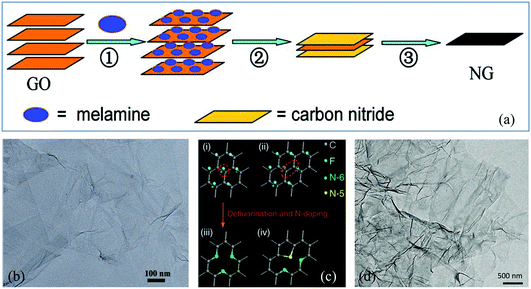 | ||
| Fig. 1 (a) Schematic illustration of the preparation of N-G via thermal annealing. (b) Transmission electron microscopy (TEM) image of N-G. Reproduced with permission from ref. 30. Copyright © 2011, American Chemical Society. (c) Schematic description of defluorination and N super-doping of a fluorinated graphite lattice. (d) TEM image of N super-doped graphene. Reproduced with permission from ref. 34. Copyright © 2016, Nature Publishing Group. | ||
2.2 Bottom-up routes
Another important route for the preparation of H-G is the bottom-up approach which involves the preparation of H-G from the assembly of carbon-containing precursors in the presence of dopants. The typical methods are chemical vapor deposition (CVD) and solvothermal reaction.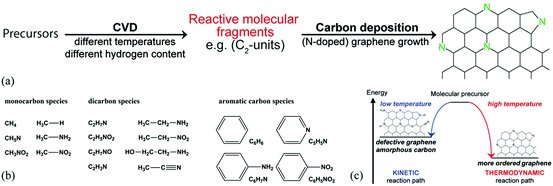 | ||
| Fig. 2 (a) Schematic formation of N-G by CVD. (b) CVD precursors with different functional groups used in this study. (c) Schematic representation of a kinetically and thermodynamically controlled reaction pathway for the formation of N-G. Reproduced with permission from ref. 54. Copyright © 2014, American Chemical Society. | ||
![[double bond, length as m-dash]](https://www.rsc.org/images/entities/char_e001.gif) C–, and –C
C–, and –C![[double bond, length as m-dash]](https://www.rsc.org/images/entities/char_e001.gif) N– groups should readily couple with each other going through further dechlorination to form graphene (Fig. 3a).58 Wurtz reaction is another typical process for graphene synthesis. The reaction between alkyl halides and alkaline metals generates carbon radicals, leading to the formation of graphene (Fig. 3b). The Baek group prepared B-G using the solvothermal Wurtz reaction between carbon tetrachloride and boron tribromide in the presence of potassium in a high-pressure reactor at 270 °C for 30 min under an argon atmosphere.59 Besides, when the reaction was performed under a nitrogen atmosphere, B,N-G was also obtained successfully.60 In addition, the Piao group prepared S-G by using a solvothermal method with dimethylsulfoxide as the single source (Fig. 3c and d).61 Generally speaking, the generation of C-containing intermediates, especially –C
N– groups should readily couple with each other going through further dechlorination to form graphene (Fig. 3a).58 Wurtz reaction is another typical process for graphene synthesis. The reaction between alkyl halides and alkaline metals generates carbon radicals, leading to the formation of graphene (Fig. 3b). The Baek group prepared B-G using the solvothermal Wurtz reaction between carbon tetrachloride and boron tribromide in the presence of potassium in a high-pressure reactor at 270 °C for 30 min under an argon atmosphere.59 Besides, when the reaction was performed under a nitrogen atmosphere, B,N-G was also obtained successfully.60 In addition, the Piao group prepared S-G by using a solvothermal method with dimethylsulfoxide as the single source (Fig. 3c and d).61 Generally speaking, the generation of C-containing intermediates, especially –C![[double bond, length as m-dash]](https://www.rsc.org/images/entities/char_e001.gif) C–, is the key point to form graphene finally during solvothermal reactions. Therefore, it would be possible to find novel processes for graphene synthesis via reactions that can form carbon radicals easily.
C–, is the key point to form graphene finally during solvothermal reactions. Therefore, it would be possible to find novel processes for graphene synthesis via reactions that can form carbon radicals easily.
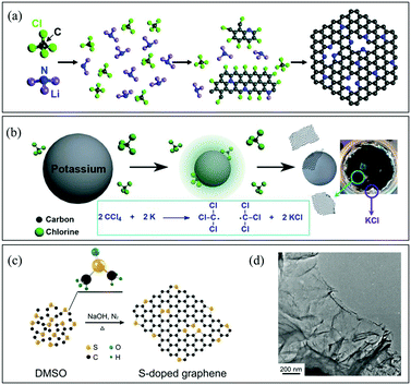 | ||
| Fig. 3 (a) Schematic description of N-G synthesis via the solvothermal reaction of CCl4 and Li3N. Reproduced with permission from ref. 58. Copyright © 2011, American Chemical Society. (b) Reaction mechanism for a solvothermal Wurtz reaction. Reproduced with permission from ref. 60. Copyright © 2014, Wiley-VCH Verlag GmbH & Co. KGaA, Weinheim. (c) Schematic description of S-G preparation via the solvothermal reaction of dimethyl sulphoxide (DMSO). (d) Scanning electron microscopy (SEM) image of S-G. Reproduced with permission from ref. 61. Copyright © 2014, Nature Publishing Group. | ||
2.3 Preparation of H-GFs
Due to the strong π–π interactions between graphene sheets, the 2D graphene flakes tend to restack when they are used as electrode materials, which can greatly reduce the specific surface area and lead to the loss of effective active sites.25 An effective way to retain the unique properties of individual graphene sheets, is to transform or assemble 2D graphene sheets into 3D GFs. At present, several strategies have been developed to construct GFs, such as CVD, gelation of GO and thermal annealing methods.25,62 When the heteroatoms are induced during the preparation of GFs, H-GFs can be achieved.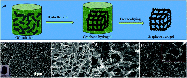 | ||
| Fig. 4 (a) Schematic illustration of the gelation of the GO method for the preparation of H-GFs. (b–e) SEM images of H-GFs obtained by different groups via the gelation of GO. (b) N-GFs. Reproduced with permission from ref. 65. Copyright © 2014, American Chemical Society. (c) B,N-GFs. Reproduced with permission from ref. 66. Copyright © 2012, Wiley-VCH Verlag GmbH & Co. KGaA, Weinheim. (d) N-GFs. Reproduced with permission from ref. 67. Copyright © 2012, Wiley-VCH Verlag GmbH & Co. KGaA, Weinheim. (e) S,P-GFs. Reproduced with permission from ref. 68. Copyright © 2016, Elsevier Ltd. | ||
2.4 Structures of H-G
The structure of graphene can be greatly modified through heteroatom doping which endows graphene with various new or enhanced functions such as catalytic activities and optoelectronic properties.19,20 Owing to the intrinsic features of each heteroatom, H-G possesses different configurations. Compared with the C atom (2s22p2), the B atom (2s22p1) has one fewer valence electron, which could induce charge polarization and p-type doping in the graphene matrix.74 B-G usually has two types, in-plane and out-of-plane doping (Fig. 5a). The former substitutes for the C atom in the graphene lattice to form the stable sp2-hybridized structure (BC3, B1 in Fig. 5a); while the latter bonds with the dangling C atoms to result in the functional groups of boronic (B2) and borinic esters (B3).27,50,74 In contrast to the B atom, the N atom (1s22s22p3) has an electron-rich nature. The main N configurations in N-G are pyridinic- (N1), pyrrolic- (N2) and graphitic-N (N3) (Fig. 5b).75 The valence electrons of P are the same as N; however, the additional orbital (3s23p3) and larger size could lead to distinct effects. The strong interaction between the 3p orbitals of P and the 2p orbitals of C could promote the transformation of sp2 C into sp3 one, resulting in a main type of pyramidal-like P in P-G (Fig. 5c).76 When O atoms exist in P-G, P–O bonds usually form.31 Unlike the doping effects of B, N, and P atoms, S-doping only leads to negligible polarization due to the similar electronegativity of the S and C atoms. The mismatch of the outermost orbitals of the S and C atoms would induce a non-uniform distribution of spin density, endowing graphene with catalytic abilities.19,20 There are two major kinds of configurations in S-G, replacing the C atoms with S or SOx to form the bonds of C–S–C (S1) or C–SOx–C (S2), respectively (Fig. 5d).72,77 For co-doped graphene, except for B,N-G which can form B–N bonds, others such as N,P-G and N,S-G usually have a random and scattered distribution of heteroatoms with similar configurations in single-heteroatom doped graphene.33,43,60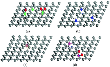 | ||
| Fig. 5 Possible configurations of heteroatoms in H-G. (a) B-G, (b) N-G, (c) P-G, and (d) S-G. The balls coloured gray, green, blue, yellow, purple and red are C, B, N, P, S and O atoms, respectively. | ||
As mentioned above, various methods have been developed to synthesize H-G. All have their own features. The CVD method can achieve H-G with high quality and high conductivity; however, it is difficult to realize mass production due to the utilization of sacrificial substrates/templates. Thermal annealing and wet chemical methods can obtain H-G on a large scale, but they usually possess low graphitization and poor conductivity resulting from the excessive defects. In fact, it is still challenging to synthesize high-quality H-G on a large scale using current technologies. Besides, the controllable synthesis of H-G with a special configuration and content is another key issue, which is closely related to catalytic activity. In general, more attention should be drawn to exploit advanced technologies towards the synthesis of H-G.
3. Applications to air cathodes
Doping heteroatoms into graphene, which either donates or withdraws free electrons, can greatly tailor the properties of graphene, and endows it with an obvious catalytic activity towards various electrochemical processes such as HOR, HER, ORR and OER.2,19 In this section, we focus on the introduction of H-G as electrocatalysts for ORR and OER which are key processes to affect the performance of air cathode-related devices, including fuel cells and metal–air batteries. For metal–air batteries, zinc–air and lithium–air batteries are emphasized because they are typical ones for aqueous and aprotic systems, respectively.3.1 Fuel cells
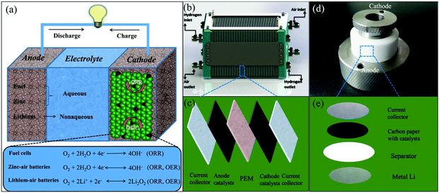 | ||
| Fig. 6 (a) Schematic diagram of the working principles for air cathode-related devices. (b) Schematic representations of a polymer electrolyte membrane fuel cell (PEMFC) stack. Reproduced with permission from ref. 79. Copyright © 2015, Hydrogen Energy Publications, LLC. Published by Elsevier Ltd. (c) Schematic diagram of the device construction in a single PEMFC. (d) Photo of a lithium–air battery and its inner structure (e). | ||
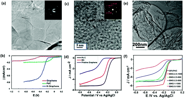 | ||
| Fig. 7 Electrochemical performance of H-G as the catalyst for ORR. (a) TEM image of N-G films grown on a grid via CVD. Inset shows the corresponding electron diffraction pattern. (b) Linear sweep voltammogram curves (LSV) of ORR on the graphene, Pt/C and N-G electrode. Reproduced with permission from ref. 55. Copyright © 2010, American Chemical Society. (c) Selected area electron diffraction (SAED) and high-resolution transmission electron microscopy (HR-TEM) images of B-G. (d) LSV curves of ORR on B-G, Pt/C and graphene electrodes. Reproduced with permission from ref. 83. Copyright © 2015, Wiley-VCH Verlag GmbH & Co. KGaA, Weinheim. (e) TEM image of B,N-G. (f) LSV curves of ORR on various B,N-G electrodes. Reproduced with permission from ref. 86. Copyright © 2014, American Chemical Society. | ||
Compared with single doped graphene, co-doped graphene may have a much better electrocatalytic performance because of the synergistic effect between different heteroatoms. B,N-G nanosheets, prepared with urea, boric acid and polyethylene glycol as precursors, exhibited a superior electrocatalytic activity compared with the commercial Pt/C electrocatalyst (Fig. 7e and f).86 N,P-G, prepared through a one-step pyrolysis of graphite oxide and hexachlorocyclotriphosphazene, effectively enhanced the ORR performance with a high onset potential, high current density, and long-term stability.33 Owing to the synergistic effect of N and S atoms, N,S-G also displayed a good catalytic activity towards ORR.87
As 3D GFs can restrain the restacking between graphene sheets effectively and expose more active sites, H-GFs have shown a much better electrochemical performance than the 2D ones.63,64,72,88–93 Yang et al. prepared highly conductive and porous 3D N-G aerogels, which displayed an enhanced power density of microbial fuel cells.64 S-GFs were prepared by using an ion-exchange/activation combination method, which showed high electrocatalytic activity, good stability and excellent methanol tolerance in alkaline solutions.72 B,N-GFs served as metal-free catalysts for ORR, showing an obviously better performance than those of N-GFs and B-GFs in terms of the onset potential, half-wave potential and diffusion limiting current density.93
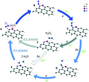 | ||
| Fig. 8 Schematic pathway for ORR on nitrogen-doped carbon materials. Reproduced with permission from ref. 97. Copyright © 2016, the American Association for the Advancement of Science. | ||
Except for N-G, the catalytic mechanisms of other H-G materials have also been investigated including single-doped and co-doped graphene.78,80,98,99 A comparative study of ORR on three graphene surfaces doped with nitrogen, boron, and phosphorus was conducted via DFT computations. A P-doped surface may offer the highest efficiency because of the lowest energies calculated for each ORR step.78 The catalytic active sites of S-G may distribute at carbon atoms located at the zigzag edges or close to the SO2 doped structure.80 For co-doping graphene, B,N-G, N has the role of an electron-withdrawing group which would indirectly activate B and thus made the latter an active site to enhance the activity.99 As for N,S-G, the dual doping of S and N introduces an asymmetrical spin and charge density, which indicates an enhanced catalytic performance.100 Overall, these studies are preliminary, and more attention should be paid in future, especially towards the synergistic effect between different heteroatoms.
3.2 Zinc–air batteries
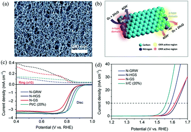 | ||
| Fig. 9 (a) SEM image of the as-synthesized 3D N-G nanoribbons. (b) Schematic diagram of ORR and OER occurring at different active sites on the n- and p-type domains of the 3D N-G nanoribbon catalyst. (c and d) ORR and OER performances of the 3D N-G nanoribbon catalyst. Reproduced with permission from ref. 71. Copyright © 2016, the Authors, some rights reserved; exclusive licensee American Association for the Advancement of Science. | ||
3.3 Lithium–air batteries
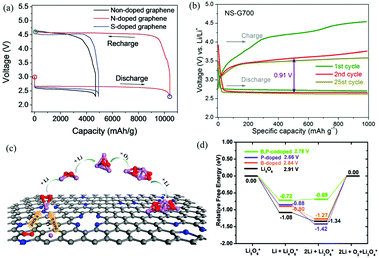 | ||
| Fig. 10 (a) Galvanostatic discharge–charge profiles of Li–O2 cells with nanoporous graphene cathodes. Reproduced with permission from ref. 23. Copyright © 2015, Wiley-VCH Verlag GmbH & Co. KGaA, Weinheim. (b) Representative voltage profiles of Li–O2 batteries with N,S-G as the electrocatalyst. Reproduced with permission from ref. 81. Copyright © 2016, American Chemical Society. (c) The ORR and initial Li2O2 nucleation processes on the surface of N-G. Reproduced with permission from ref. 116. Copyright © 2015, American Chemical Society. (d) The thermodynamic OER pathways on B,P-G. For comparison, the OER pathways of pure Li5O6, Li5O6 adsorbed on B-G and P-G are also displayed. Reproduced with permission from ref. 117. Copyright © 2015, the Owner Societies. | ||
3.4 Other applications
As well as its applications in fuel cells and metal–air batteries, H-G can also be used for other catalysis-related devices such as electrochemical sensors and solar cells.20,74,119 Owing to the polarization from dopant sites, H-G can possess electrocatalytic functions to selectively bind chemical species such as NOx, hydroquinone, catechol and guanine, which makes it possible to act as active materials for electrochemical sensors.74,120 In addition, as heteroatom doping can endow graphene with an n- or p-type semiconducting behavior, H-G can work as the catalyst in solar cells and reduce the charge transfer resistance of the active layer, leading to an enhanced power conversion efficiency.20,121 All in all, H-G-based materials are promising catalysts for many devices, and in the near future their commercial applications may become apparent.4. Summary and outlook
Fuel cells and metal–air batteries are promising energy storage and conversion devices owing to their ultrahigh theoretical energy density. However, it is still challenging to achieve the super-high energy density in practical applications at present. One of the key issues is the sluggish electrochemical reaction kinetics on the air cathodes, which makes it quite necessary to exploit high-efficiency electrocatalysts. In the past decade, H-G materials have drawn extensive attention due to their good catalytic activity, large specific surface area and high electrical conductivity. In this review, we focus on the discussion of H-G as electrocatalysts for air cathodes in energy storage and conversion devices, including the preparation methods of H-G and their applications to fuel cells, zinc–air batteries and lithium–air batteries. Although significant progress has been made, the studies are still in their infancy with many challenges remaining.As mentioned above, various methods have been developed to prepare H-G. However, it is difficult to prepare H-G with high quality and mass production simultaneously, which would hinder the progress of their commercialization. For example, the CVD method can achieve H-G with high quality and high conductivity; however, it is difficult to realize mass production due to the utilization of sacrificial templates; thermal annealing and wet chemical methods can obtain H-G on a large scale, but they usually possess low graphitization and poor conductivity resulting from excessive defects. Furthermore, another key issue for the preparation of H-G is the controllable preparation of H-G with special configurations. Currently, the obtained H-G materials usually contain multiple configurations which make it difficult to ensure the catalytic active sites accurately. In addition, it is also important to adjust the doping level. At present, except for that of N-G, the doping levels of other H-G are usually quite low, which could be unfavorable for their electrochemical performance. In general, more attention should be paid to exploit advanced technologies towards the preparation of H-G.
With H-G as the electrocatalyst, the performance of air cathode-related devices has been clearly improved. However, it is still far from the requirement for practical applications. The main obstacle is the exploitation of high-efficiency electrocatalysts. As already known, an excellent catalyst should have highly catalytic active sites with adequate quantity. Therefore, the exploration of high-efficiency H-G-based electrocatalysts can be performed from two aspects, types and numbers of active sites.
As the catalytic sites in H-G materials are closely related to the kinds and configurations of heteroatoms, several strategies can be attempted to obtain highly active sites. Firstly, finding ways to prepare H-G with special configurations such as pyridinic-N or graphitic-N in N-G is the most critical issue to ensure the type of catalytic sites. Unfortunately, it still has huge challenges. The adjustment technologies on the atomic level may be promising, and more attention should be paid to these in future. Besides, owing to the synergistic effect, co-doped graphene may display a much better performance than single-doped graphene. Therefore, doping graphene with different heteroatoms may be an effective route to obtain high-efficiency electrocatalysts. In addition, the exploitation of bifunctional electrocatalysts towards both ORR and OER is of great significance for achieving an improved performance in metal–air batteries. Because of the difference in reaction processes, the catalytic active sites of H-G for ORR and OER are different, which makes it valuable for controllable synthesis of H-G with different active sites on special reaction regions.
The numbers of catalytic active sites in H-G are connected with the doping level and their structures. On the one hand, the high-level doping can increase the quantity of active sites. Therefore, it is necessary to develop advanced technologies to realize the high-level doping. On the other hand, a large special surface area and suitable pore distribution can increase the numbers of accessible active sites. Therefore, in order to obtain an adequate quantity of accessible catalytic active sites, more work should be done to adjust the structure of H-G. One feasible approach is to construct H-G with a 3D framework structure. Compared with the 2D ones, 3D H-GFs have remarkable advantages. Firstly, H-GFs can restrain the restacking between graphene sheets during the applications, which would increase the effective specific surface area, leading to more accessible active sites. Secondly, H-GFs can offer multiple routes for electron transfer, enhancing the conductivity of the whole electrodes. Thirdly, the macropores in H-GFs can work as reservoirs of electrolytes, which would reduce the distance of ion transport and accelerate the reaction rates.
Except for the tentative strategies mentioned above to achieve high-efficiency electrocatalysts, the investigation of catalytic reaction mechanisms is also of significance, which can guide the exploitation of excellent electrocatalysts. Due to the limits of the current approaches, the study of the catalytic reaction mechanism of H-G is still insufficient, especially the OER process in Li–air batteries. To make the reaction mechanism more clear, more attention should be paid to this in future. On the one hand, advanced experimental technologies should be developed to detect the real reaction process such as the in situ measurements of Raman, X-ray diffraction, and X-ray photoelectric spectroscopy. On the other hand, the simulated conditions used in theoretical computations should be much closer to the actual systems.
Acknowledgements
This work was supported by the NSFC (21473094 and 21421001) and MOST (2016YFA0200200) in China.References
- F. Bonaccorso, L. Colombo, G. Yu, M. Stoller, V. Tozzini, A. C. Ferrari, R. S. Ruoff and V. Pellegrini, Science, 2015, 347, 1246501 CrossRef PubMed
.
- L. Dai, Y. Xue, L. Qu, H.-J. Choi and J.-B. Baek, Chem. Rev., 2015, 115, 4823–4892 CrossRef CAS PubMed
.
- L. Ye, K. Wen, Z. Zhang, F. Yang, Y. Liang, W. Lv, Y. Lin, J. Gu, J. H. Dickerson and W. He, Adv. Energy Mater., 2016, 6, 1502018 CrossRef
.
- S. Mekhilef, R. Saidur and A. Safari, Renewable Sustainable Energy Rev., 2012, 16, 981–989 CrossRef CAS
.
- F. Cheng and J. Chen, Chem. Soc. Rev., 2012, 41, 2172–2192 RSC
.
- Y. Zhong, M. Yang, X. Zhou and Z. Zhou, Mater. Horiz., 2015, 2, 553–566 RSC
.
- F. Wang, C. Hu, M. Zhou, K. Wang, J. Lian, J. Yan, S. Cheng and K. Jiang, Sci. Bull., 2016, 61, 451–458 CrossRef CAS
.
- B. Liu, J.-G. Zhang and G. Shen, Nano Today, 2016, 11, 82–97 CrossRef CAS
.
- B. Diouf and R. Pode, Renewable Energy, 2015, 76, 375–380 CrossRef
.
- L. Grande, E. Paillard, J. Hassoun, J. B. Park, Y. J. Lee, Y. K. Sun, S. Passerini and B. Scrosati, Adv. Mater., 2015, 27, 784–800 CrossRef CAS PubMed
.
- J.-S. Lee, S. Tai Kim, R. Cao, N.-S. Choi, M. Liu, K. T. Lee and J. Cho, Adv. Energy Mater., 2011, 1, 34–50 CrossRef CAS
.
- N. Feng, P. He and H. Zhou, Adv. Energy Mater., 2016, 6, 1502303 CrossRef
.
- B. Lim, M. Jiang, P. H. Camargo, E. C. Cho, J. Tao, X. Lu, Y. Zhu and Y. Xia, Science, 2009, 324, 1302–1305 CrossRef CAS PubMed
.
- Y. Lee, J. Suntivich, K. J. May, E. E. Perry and Y. Shao-Horn, J. Phys. Chem. Lett., 2012, 3, 399–404 CrossRef CAS PubMed
.
- Z.-L. Wang, D. Xu, J.-J. Xu and X.-B. Zhang, Chem. Soc. Rev., 2014, 43, 7746–7786 RSC
.
- H. Hu, J. H. Xin, H. Hu, X. Wang and Y. Kong, Appl. Catal., A, 2015, 492, 1–9 CrossRef CAS
.
- L. Borchardt, M. Oschatz and S. Kaskel, Mater. Horiz., 2014, 1, 157–168 RSC
.
- Y. Zhai, Y. Dou, D. Zhao, P. F. Fulvio, R. T. Mayes and S. Dai, Adv. Mater., 2011, 23, 4828–4850 CrossRef CAS PubMed
.
- J. Duan, S. Chen, M. Jaroniec and S. Z. Qiao, ACS Catal., 2015, 5, 5207–5234 CrossRef CAS
.
- X. Wang, G. Sun, P. Routh, D. H. Kim, W. Huang and P. Chen, Chem. Soc. Rev., 2014, 43, 7067–7098 RSC
.
- Y. Deng, Y. Xie, K. Zou and X. Ji, J. Mater. Chem. A, 2016, 4, 1144–1173 RSC
.
- M. D. Stoller, S. Park, Y. Zhu, J. An and R. S. Ruoff, Nano Lett., 2008, 8, 3498–3502 CrossRef CAS PubMed
.
- J. Han, X. Guo, Y. Ito, P. Liu, D. Hojo, T. Aida, A. Hirata, T. Fujita, T. Adschiri, H. Zhou and M. Chen, Adv. Energy Mater., 2016, 6, 1501870 CrossRef
.
- J. Liu, P. Song, Z. Ning and W. Xu, Electrocatalysis, 2015, 6, 132–147 CrossRef CAS
.
- B. Luo and L. Zhi, Energy Environ. Sci., 2015, 8, 456–477 Search PubMed
.
- R. S. Edwards and K. S. Coleman, Nanoscale, 2013, 5, 38–51 RSC
.
- H. Fang, C. Yu, T. Ma and J. Qiu, Chem. Commun., 2014, 50, 3328–3330 RSC
.
- M. Vikkisk, I. Kruusenberg, U. Joost, E. Shulga, I. Kink and K. Tammeveski, Appl. Catal., B, 2014, 147, 369–376 CrossRef CAS
.
- E. Haque, M. M. Islam, E. Pourazadi, M. Hassan, S. N. Faisal, A. K. Roy, K. Konstantinov, A. T. Harris, A. I. Minett and V. G. Gomes, RSC Adv., 2015, 5, 30679–30686 RSC
.
- Z.-H. Sheng, L. Shao, J.-J. Chen, W.-J. Bao, F.-B. Wang and X.-H. Xia, ACS Nano, 2011, 5, 4350–4358 CrossRef CAS PubMed
.
- R. Li, Z. Wei, X. Gou and W. Xu, RSC Adv., 2013, 3, 9978–9984 RSC
.
- S. Wang, L. Zhang, Z. Xia, A. Roy, D. W. Chang, J. B. Baek and L. Dai, Angew. Chem., Int. Ed., 2012, 51, 4209–4212 CrossRef CAS PubMed
.
- L. Dong, C. Hu, X. Huang, N. Chen and L. Qu, Chem. – Asian J., 2015, 10, 2609–2614 CrossRef CAS PubMed
.
- Y. Liu, Y. Shen, L. Sun, J. Li, C. Liu, W. Ren, F. Li, L. Gao, J. Chen, F. Liu, Y. Sun, N. Tang, H.-M. Cheng and Y. Du, Nat. Commun., 2016, 7, 10921 CrossRef CAS PubMed
.
- H. L. Poh, P. Simek, Z. Sofer and M. Pumera, ACS Nano, 2013, 7, 5262–5272 CrossRef CAS PubMed
.
- J. Borowiec and J. Zhang, J. Electrochem. Soc., 2015, 162, B332–B336 CrossRef CAS
.
- J. Li, X. Li, P. Zhao, D. Y. Lei, W. Li, J. Bai, Z. Ren and X. Xu, Carbon, 2015, 84, 460–468 CrossRef CAS
.
- H. Zhang, T. Kuila, N. H. Kim, D. S. Yu and J. H. Lee, Carbon, 2014, 69, 66–78 CrossRef CAS
.
- Y. Zhang, K. Fugane, T. Mori, L. Niu and J. Ye, J. Mater. Chem., 2012, 22, 6575–6580 RSC
.
- B. Jiang, C. Tian, L. Wang, L. Sun, C. Chen, X. Nong, Y. Qiao and H. Fu, Appl. Surf. Sci., 2012, 258, 3438–3443 CrossRef CAS
.
- L. Zhao, B. Yu, F. Xue, J. Xie, X. Zhang, R. Wu, R. Wang, Z. Hu, S. T. Yang and J. Luo, J. Hazard. Mater., 2015, 286, 449–456 CrossRef CAS PubMed
.
- G. Chen, Y. Liu, Y. Liu, Y. Tian and X. Zhang, J. Electroanal. Chem., 2015, 738, 100–107 CrossRef CAS
.
- A. G. Kannan, J. Zhao, S. G. Jo, Y. S. Kang and D.-W. Kim, J. Mater. Chem. A, 2014, 2, 12232–12239 RSC
.
- N. Li, Z. Wang, K. Zhao, Z. Shi, Z. Gu and S. Xu, Carbon, 2010, 48, 255–259 CrossRef CAS
.
- S. Dey, A. Govindaraj, K. Biswas and C. N. R. Rao, Chem. Phys. Lett., 2014, 595–596, 203–208 CrossRef CAS
.
- H. M. Jeong, J. W. Lee, W. H. Shin, Y. J. Choi, H. J. Shin, J. K. Kang and J. W. Choi, Nano Lett., 2011, 11, 2472–2477 CrossRef CAS PubMed
.
- I. Y. Jeon, H. J. Choi, S. M. Jung, J. M. Seo, M. J. Kim, L. Dai and J. B. Baek, J. Am. Chem. Soc., 2013, 135, 1386–1393 CrossRef CAS PubMed
.
- Y. Zhang, L. Zhang and C. Zhou, Acc. Chem. Res., 2013, 46, 2329–2339 CrossRef CAS PubMed
.
- C.-M. Seah, S.-P. Chai and A. R. Mohamed, Carbon, 2014, 70, 1–21 CrossRef CAS
.
- H. Wang, Y. Zhou, D. Wu, L. Liao, S. Zhao, H. Peng and Z. Liu, Small, 2013, 9, 1316–1320 CrossRef CAS PubMed
.
- Y. Sui, B. Zhu, H. Zhang, H. Shu, Z. Chen, Y. Zhang, Y. Zhang, B. Wang, C. Tang, X. Xie, G. Yu, Z. Jin and X. Liu, Carbon, 2015, 81, 814–820 CrossRef CAS
.
- G. V. Bianco, M. Losurdo, M. M. Giangregorio, P. Capezzuto and G. Bruno, Phys. Chem. Chem. Phys., 2014, 16, 3632–3639 RSC
.
- D. Wei, Y. Liu, Y. Wang, H. Zhang, L. Huang and G. Yu, Nano Lett., 2009, 9, 1752–1758 CrossRef CAS PubMed
.
- Y. Ito, C. Christodoulou, M. V. Nardi, N. Koch, H. Sachdev and K. Muellen, ACS Nano, 2014, 8, 3337–3346 CrossRef CAS PubMed
.
- L. Qu, Y. Liu, J.-B. Baek and L. Dai, ACS Nano, 2010, 4, 1321–1326 CrossRef CAS PubMed
.
- F. Hassani, H. Tavakol, F. Keshavarzipour and A. Javaheri, RSC Adv., 2016, 6, 27158–27163 RSC
.
- C. Liang, Y. Wang and T. Li, Carbon, 2015, 82, 506–512 CrossRef CAS
.
- D. Deng, X. Pan, L. Yu, Y. Cui, Y. Jiang, J. Qi, W.-X. Li, Q. Fu, X. Ma, Q. Xue, G. Sun and X. Bao, Chem. Mater., 2011, 23, 1188–1193 CrossRef CAS
.
- S.-M. Jung, I. T. Choi, K. Lim, J. Ko, J. C. Kim, J.-J. Lee, M. J. Ju, H. K. Kim and J.-B. Baek, Chem. Mater., 2014, 26, 3586–3591 CrossRef CAS
.
- S. M. Jung, E. K. Lee, M. Choi, D. Shin, I. Y. Jeon, J. M. Seo, H. Y. Jeong, N. Park, J. H. Oh and J. B. Baek, Angew. Chem., Int. Ed., 2014, 53, 2398–2401 CrossRef CAS PubMed
.
- B. Quan, S. H. Yu, D. Y. Chung, A. Jin, J. H. Park, Y. E. Sung and Y. Piao, Sci. Rep., 2014, 4, 5639 CrossRef CAS PubMed
.
- Y. Xu, G. Shi and X. Duan, Acc. Chem. Res., 2015, 48, 1666–1675 CrossRef CAS PubMed
.
- Y. Xue, D. Yu, L. Dai, R. Wang, D. Li, A. Roy, F. Lu, H. Chen, Y. Liu and J. Qu, Phys. Chem. Chem. Phys., 2013, 15, 12220–12226 RSC
.
- Y. Yang, T. Liu, X. Zhu, F. Zhang, D. Ye, Q. Liao and Y. Li, Adv. Sci., 2016, 3, 1600097 CrossRef PubMed
.
- Z. Y. Sui, Y. N. Meng, P. W. Xiao, Z. Q. Zhao, Z. X. Wei and B. H. Han, ACS Appl. Mater. Interfaces, 2015, 7, 1431–1438 Search PubMed
.
- Z.-S. Wu, A. Winter, L. Chen, Y. Sun, A. Turchanin, X. Feng and K. Muellen, Adv. Mater., 2012, 24, 5130–5135 CrossRef CAS PubMed
.
- Y. Zhao, C. G. Hu, Y. Hu, H. H. Cheng, G. Q. Shi and L. T. Qu, Angew. Chem., Int. Ed., 2012, 51, 11371–11375 CrossRef CAS PubMed
.
- X. Yu, Y. Kang and H. S. Park, Carbon, 2016, 101, 49–56 CrossRef CAS
.
- Y. Wen, T. E. Rufford, D. Hulicova-Jurcakova and L. Wang, ChemSusChem, 2016, 9, 513–520 CrossRef CAS PubMed
.
- H. J. Cui, H. M. Yu, J. F. Zheng, Z. J. Wang, Y. Y. Zhu, S. P. Jia, J. Jia and Z. P. Zhu, Nanoscale, 2016, 8, 2795–2803 RSC
.
- H. B. Yang, J. Miao, S. F. Hung, J. Chen, H. B. Tao, X. Wang, L. Zhang, R. Chen, J. Gao, H. M. Chen, L. Dai and B. Liu, Sci. Bull., 2016, 2, e1501122 Search PubMed
.
- Y. Zhang, M. Chu, L. Yang, W. Deng, Y. Tan, M. Ma and Q. Xie, Chem. Commun., 2014, 50, 6382–6385 RSC
.
- T. Akhter, M. M. Islam, S. N. Faisal, E. Haque, A. I. Minett, H. K. Liu, K. Konstantinov and S. X. Dou, ACS Appl. Mater. Interfaces, 2016, 8, 2078–2087 Search PubMed
.
- S. Agnoli and M. Favaro, J. Mater. Chem. A, 2016, 4, 5002–5025 RSC
.
- H. Wang, T. Maiyalagan and X. Wang, ACS Catal., 2012, 2, 781–794 CrossRef CAS
.
- H.-m. Wang, H.-x. Wang, Y. Chen, Y.-j. Liu, J.-x. Zhao, Q.-h. Cai and X.-z. Wang, Appl. Surf. Sci., 2013, 273, 302–309 CrossRef CAS
.
- Z. Yang, Z. Yao, G. Li, G. Fang, H. Nie, Z. Liu, X. Zhou, X. a. Chen and S. Huang, ACS Nano, 2012, 6, 205–211 CrossRef CAS PubMed
.
- M. del Cueto, P. Ocón and J. M. L. Poyato, J. Phys. Chem. C, 2015, 119, 2004–2009 CrossRef CAS
.
- Y. Devrim, H. Devrim and I. Eroglu, Int. J. Hydrogen Energy, 2015, 40, 7707–7719 CrossRef CAS
.
- L. Zhang, J. Niu, M. Li and Z. Xia, J. Phys. Chem. C, 2014, 118, 3545–3553 CrossRef CAS
.
- H. Huang, J. Zhu, W. Zhang, C. S. Tiwary, J. Zhang, X. Zhang, Q. Jiang, H. He, Y. Wu, W. Huang, P. M. Ajayan and Q. Yan, Chem. Mater., 2016, 28, 1737–1745 CrossRef CAS
.
- L. Zhang, J. Niu, L. Dai and Z. Xia, Langmuir, 2012, 28, 7542–7550 CrossRef CAS PubMed
.
- T. V. Vineesh, M. P. Kumar, C. Takahashi, G. Kalita, S. Alwarappan, D. K. Pattanayak and T. N. Narayanan, Adv. Energy Mater., 2015, 5, 1500658 CrossRef
.
- X. Bai, Y. Shi, J. Guo, L. Gao, K. Wang, Y. Du and T. Ma, J. Power Sources, 2016, 306, 85–91 CrossRef CAS
.
- X. Fu, J. Jin, Y. Liu, Z. Wei, F. Pan and J. Zhang, ACS Appl. Mater. Interfaces, 2014, 6, 3930–3936 Search PubMed
.
- J. Jin, F. Pan, L. Jiang, X. Fu, A. Liang, Z. Wei, J. Zhang and G. Sun, ACS Nano, 2014, 8, 3313–3321 CrossRef CAS PubMed
.
- J.-M. You, M. S. Ahmed, H. S. Han, J. e. Choe, Z. Üstündağ and S. Jeon, J. Power Sources, 2015, 275, 73–79 CrossRef CAS
.
- L. Chen, X. Cui, Y. Wang, M. Wang, R. Qiu, Z. Shu, L. Zhang, Z. Hua, F. Cui, C. Wei and J. Shi, Dalton Trans., 2014, 43, 3420–3423 RSC
.
- Y. Zhou, C. H. Yen, S. Fu, G. Yang, C. Zhu, D. Du, P. C. Wo, X. Cheng, J. Yang, C. M. Wai and Y. Lin, Green Chem., 2015, 17, 3552–3560 RSC
.
- Z. Lin, G. H. Waller, Y. Liu, M. Liu and C.-p. Wong, Nano Energy, 2013, 2, 241–248 CrossRef CAS
.
- Y. Ito, H. J. Qiu, T. Fujita, Y. Tanabe, K. Tanigaki and M. Chen, Adv. Mater., 2014, 26, 4145–4150 CrossRef CAS PubMed
.
- X. Chen, X. Chen, X. Xu, Z. Yang, Z. Liu, L. Zhang, X. Xu, Y. Chen and S. Huang, Nanoscale, 2014, 6, 13740–13747 RSC
.
- C. Xu, Y. Su, D. Liu and X. He, Phys. Chem. Chem. Phys., 2015, 17, 25440–25448 RSC
.
- H. Kim, K. Lee, S. I. Woo and Y. Jung, Phys. Chem. Chem. Phys., 2011, 13, 17505–17510 RSC
.
- L. Yu, X. Pan, X. Cao, P. Hu and X. Bao, J. Catal., 2011, 282, 183–190 CrossRef CAS
.
- L. Zhang and Z. Xia, J. Phys. Chem. C, 2011, 115, 11170–11176 CrossRef CAS
.
- D. Guo, R. Shibuya, C. Akiba, S. Saji, T. Kondo and J. Nakamura, Science, 2016, 351, 361–365 CrossRef CAS PubMed
.
- X. Zhang, Z. Lu, Z. Fu, Y. Tang, D. Ma and Z. Yang, J. Power Sources, 2015, 276, 222–229 CrossRef CAS
.
- Y. Zheng, Y. Jiao, L. Ge, M. Jaroniec and S. Z. Qiao, Angew. Chem., Int. Ed., 2013, 52, 3110–3116 CrossRef CAS PubMed
.
- J. Liang, Y. Jiao, M. Jaroniec and S. Z. Qiao, Angew. Chem., Int. Ed., 2012, 51, 11496–11500 CrossRef CAS PubMed
.
- Y. Li and H. Dai, Chem. Soc. Rev., 2014, 43, 5257–5275 RSC
.
- A. Vignesh, M. Prabu and S. Shanmugam, ACS Appl. Mater. Interfaces, 2016, 8, 6019–6031 Search PubMed
.
- P.-C. Li, Y.-J. Chien and C.-C. Hu, J. Power Sources, 2016, 313, 37–45 CrossRef CAS
.
- G. Li, X. Wang, J. Fu, J. Li, M. G. Park, Y. Zhang, G. Lui and Z. Chen, Angew. Chem., Int. Ed., 2016, 55, 4977–4982 CrossRef CAS PubMed
.
- D. U. Lee, H. W. Park, D. Higgins, L. Nazar and Z. Chen, J. Electrochem. Soc., 2013, 160, F910–F915 CrossRef CAS
.
- D. Higgins, Z. Chen, D. U. Lee and Z. Chen, J. Mater. Chem. A, 2013, 1, 2639–2645 RSC
.
- M. Li, L. Zhang, Q. Xu, J. Niu and Z. Xia, J. Catal., 2014, 314, 66–72 CrossRef CAS
.
- Y. Jia, L. Zhang, A. Du, G. Gao, J. Chen, X. Yan, C. L. Brown and X. Yao, Adv. Mater., 2016 DOI:10.1002/adma.201602912
.
- R. Li, Z. Wei and X. Gou, ACS Catal., 2015, 5, 4133–4142 CrossRef CAS
.
- P. He, T. Zhang, J. Jiang and H. Zhou, J. Phys. Chem. Lett., 2016, 7, 1267–1280 CrossRef CAS PubMed
.
- Z. L. Wang, D. Xu, J. J. Xu and X. B. Zhang, Chem. Soc. Rev., 2014, 43, 7746–7786 RSC
.
- J.-H. Kim, A. G. Kannan, H.-S. Woo, D.-G. Jin, W. Kim, K. Ryu and D.-W. Kim, J. Mater. Chem. A, 2015, 3, 18456–18465 RSC
.
- X. Ren, J. Zhu, F. Du, J. Liu and W. Zhang, J. Phys. Chem. C, 2014, 118, 22412–22418 CrossRef CAS
.
- Y. Li, J. Wang, X. Li, D. Geng, M. N. Banis, R. Li and X. Sun, Electrochem. Commun., 2012, 18, 12–15 CrossRef CAS
.
- T. Yuan, W. Zhang, W.-T. Li, C. Song, Y.-S. He, J. M. Razal, Z. F. Ma and J. Chen, 2D Mater., 2015, 2, 024002 CrossRef
.
- Y. Jing and Z. Zhou, ACS Catal., 2015, 5, 4309–4317 CrossRef CAS
.
- X. Ren, B. Wang, J. Zhu, J. Liu, W. Zhang and Z. Wen, Phys. Chem. Chem. Phys., 2015, 17, 14605–14612 RSC
.
- H. R. Jiang, T. S. Zhao, L. Shi, P. Tan and L. An, J. Phys. Chem. C, 2016, 120, 6612–6618 CrossRef CAS
.
- U. N. Maiti, W. J. Lee, J. M. Lee, Y. Oh, J. Y. Kim, J. E. Kim, J. Shim, T. H. Han and S. O. Kim, Adv. Mater., 2014, 26, 40–67 CrossRef CAS PubMed
.
- Y. Zhang, R. Sun, B. Luo and L. Wang, Electrochim. Acta, 2015, 156, 228–234 CrossRef CAS
.
- M. J. Ju, J. C. Kim, H.-J. Choi, I. T. Choi, S. G. Kim, K. Lim, J. Ko, J.-J. Lee, I.-Y. Jeon, J.-B. Baek and H. K. Kim, ACS Nano, 2013, 7, 5243–5250 CrossRef CAS PubMed
.
| This journal is © The Royal Society of Chemistry 2017 |


