 Open Access Article
Creative Commons Attribution 3.0 Unported Licence
Gateway state-mediated, long-range tunnelling in molecular wires†‡
Sara
Sangtarash§
 *a,
Andrea
Vezzoli§
 b,
Hatef
Sadeghi
 a,
Nicolò
Ferri
 b,
Harry M.
O'Brien
b,
Iain
Grace
b,
Harry M.
O'Brien
b,
Iain
Grace
 a,
Laurent
Bouffier¶
 b,
Simon J.
Higgins
 *b,
Richard J.
Nichols
 b and
Colin J.
Lambert
 *a
*a
aQuantum Technology Centre, Physics Department, Lancaster University, Lancaster LA1 4YB, UK. E-mail: c.lambert@lancaster.ac.uk; s.sangtarash@lancaster.ac.uk
bDepartment of Chemistry, University of Liverpool, Crown Street, Liverpool L69 7ZD, UK. E-mail: shiggins@liverpool.ac.uk
First published on 29th January 2018
Abstract
If the factors controlling the decay in single-molecule electrical conductance G with molecular length L could be understood and controlled, then this would be a significant step forward in the design of high-conductance molecular wires. For a wide variety of molecules conducting by phase coherent tunnelling, conductance G decays with length following the relationship G = Ae−βL. It is widely accepted that the attenuation coefficient β is determined by the position of the Fermi energy of the electrodes relative to the energy of frontier orbitals of the molecular bridge, whereas the terminal anchor groups which bind to the molecule to the electrodes contribute to the pre-exponential factor A. We examine this premise for several series of molecules which contain a central conjugated moiety (phenyl, viologen or α-terthiophene) connected on either side to alkane chains of varying length, with each end terminated by thiol or thiomethyl anchor groups. In contrast with this expectation, we demonstrate both experimentally and theoretically that additional electronic states located on thiol anchor groups can significantly decrease the value of β, by giving rise to resonances close to EF through coupling to the bridge moiety. This interplay between the gateway states and their coupling to a central conjugated moiety in the molecular bridges creates a new design strategy for realising higher-transmission molecular wires by taking advantage of the electrode–molecule interface properties.
Introduction
Understanding electron transport in metal–molecule–metal (MMM) junctions and identifying molecular wires whose conductance decays only slowly with length is important for the advancement of molecular electronics. The critical factors which determine conductance in a MMM junctions are the metal–molecule contacts and the structure of the molecular backbone.1 While a wide variety of molecular backbones can be synthesised, the nature of the anchor groups that act as connectors to the metallic leads is limited by the strength of their interaction with the metal. As gold is the most widely used electrode material in molecular electronics, the choice of anchor can be made from moieties that can form X–Au covalent bonds, such as thiols2,3 and carbodithioates,4 moieties that react to give a C–Au bond, such as organostannanes5 or diazonium salts,6 and moieties that interact with gold with a coordination bond, such thiomethyls,7–9 amines,7,10 pyridines,11–13 and phosphines.10Tunnelling theory predicts that conductance across a nanojunction should decay exponentially with its length, following a relationship G = Ae−βL, where L is the junction length and A is a pre-exponential factor dependent on junction contacts and nature of metallic leads. The nature of the molecular wire bridging the two metallic leads has a strong effect on the exponential attenuation factor β, as demonstrated by Wold et al. in 2002.14 Conjugated molecular wires such as oligophenylene exhibit conductance values that decay with increasing number of phenyl units to the extent of β = 0.41 Å−1, and other conjugated systems such as oligophenyleneimine15 and oligonaphthalenefluoreneimine16 showed lower attenuation factors of 0.3 Å−1 and 0.25 Å−1, respectively. Extremely low values of β were found in systems such as meso-to-meso bridged oligoporphyrins13,17,18 (0.040 ± 0.006 Å−1), axially-bridged oligoporphyrins19 (0.015 ± 0.006 Å−1), oligoynes20 (0.06 ± 0.03 Å−1), carbodithioate-capped oligophenylene-ethynylene4 (0.05 ± 0.01 Å−1), and extended viologens21 (0.006 ± 0.004 Å−1). Oligothiophenes, on the other hand, showed a more complex behaviour, with unusual conductance decay with the number of thiophene rings22–24 and, in the case of longer oligothiophenes with alkylthiol linkers, water-dependent conductance and conductance decay.25 A hopping charge-transport mechanism could explain the low value of β in some of these systems, but it is generally believed that tunnelling is dominant in short molecular wires. Transition from tunnelling to hopping has been observed in various systems, at a critical length ranging from 5 nm (oligonaphthalenefluoreneimine)16 to 8 nm (oligothiophene).26
The length-dependent conductance of alkanedithiols (as archetypal saturated molecular wires) has been the subject of investigation by several research groups. Li et al.27 reported exponential decrease of the conductance with molecular length with β ≈ 0.84 Å−1 for N(CH2) < 7. Other studies with longer alkanedithiols showed that the conductance decay is less pronounced for shorter molecules (N(CH2) < 8), whereas conductance decay is more rapid for longer lengths (N(CH2) > 8).28,29 Another study reports experimental decay constants β ≈ 0.94–0.96 Å−1.30 Inclusion of heteroatom in the aliphatic alkyl chain to give oligoethers or oligothioethers resulted in negligible effect on β, with reported values of 1.11 (per atom unit) for alkanedithiols, 1.19 for oligoethers and 1.17 for oligothioethers.31
The above comprehensive experiments, combined with detailed modelling and material-specific transport calculations, take into account complex features introduced by metal–molecule contact,32–34 orbital resonances, and other quantum mechanical effects that can strongly affect molecular conductance.14,23,35–40 They have improved our understanding of the conductance decay with length in MMM junctions, but the effect of the molecular wire structure on the value of β is still not completely understood. An important feature in the transport characteristics of alkanedithiols is the presence of a broad resonance, called in previous studies a “gateway state”41 or “contact-level”,30 close in energy to the Fermi level of the metallic leads. In a systematic study of alkane molecular junctions with gold electrodes, Kim et al., reported a small peak close to the Fermi energy and a broad one about −1 eV from the Fermi energy, and they showed that the resonances are due to molecular orbitals localized on sulfur at these energies.42 This peak is also present in the calculations of Hüser et al. in the case of thiol end-groups connected to a tip terminated with a single gold atom.43
We found that the presence of a central group attached via thiol-terminated alkane linkers to Au electrodes will magnify the effect of the resonance peak close to the Fermi energy, and we attribute this feature to atomic wave functions localised on sulfur atoms bound to the leads. The phenomenon is not limited to thiol contacts, and it has also been observed in MMM junctions with covalent, highly conducting C–Au contacts.44 In what follows, we reveal the peculiar effect of these gateway orbitals on the decay constant β. In the conductance-length relationship G = Ae−βL, the attenuation coefficient β(EF) is a property of the backbone and the value of the electrode Fermi energy EF relative to the frontier orbitals of the molecule, which determines the tunnelling gap for electrons passing from one electrode to the other. On the other hand, for a given EF, it is often assumed that the coupling between the anchor groups and electrodes contributes to the prefactor A only. This assumption is surely correct in the asymptotic limit of large L, providing transport takes place by phase-coherent tunnelling. However, β is usually obtained experimentally from the slope of plots of ln(G) versus L, for limited values of L, and the question of whether these values are sufficiently large is usually not addressed. However, there are some exceptions. For instance, Xie et al. have shown that, for junctions formed using conducting atomic force microscopy (C-AFM) measurements on monolayers of short oligophenyl molecules, the value of β depended upon whether mono- or dithiols were employed,45 being smaller in the latter case. In what follows, we refer to the slopes of such graphs as pseudo-attenuation coefficients and denote them β′. The main reason for doing this is that here we add methylene groups at either side of the central moiety, rather than having a homologous series incrementing by monomer units, the latter being the most widely used for the determination of attenuation factors β. The assumption that the coupling between the anchor groups and electrodes contributes to the prefactor A only has restricted the range of proposed strategies for manipulating β to those which mainly rely on tuning EF by electrochemical or electrostatic gating, or by doping the backbone with electron donors or acceptors. The aim of the present paper is to demonstrate the counterintuitive result that the coupling between anchor groups and electrodes can contribute to both the β′ and the prefactor A. In this work we demonstrate this dependence, both experimentally and theoretically, by studying the length-dependent conductance of molecules containing a central conjugated moiety connected on either side to alkane chains of varying length.
As shown in Fig. 1, the central units are chosen to be either an α-terthiophene (X[T3]X), a phenyl (X[Ph]X) or a viologen (X[V]X) moiety, and the alkane chains (varying in length from 1 to 9 methylene units each) are sulfur-capped to provide a strong connection to the gold electrodes. The nature of the central unit has been demonstrated to have a strong effect on molecular conductance,46,47 and therefore we chose these three different moieties on the basis of their extent of conjugation and electron density, going from a poorly-conjugated, electron-deficient moiety such as a viologen salt (with a break in conjugation due to inter-ring torsion in its dication state48) to the well-conjugated, electron-rich α-terthiophene. Intuitively, one might expect the value of β′ for these molecular wires to approach the value determined for alkanedithiols (β ≈ 1 Å−1). Surprisingly, in what follows we shall demonstrate that the presence of a conjugated moiety in the alkyl tunnelling barrier strongly affects β′, due to transport through “gateway states” and “coupling states”, the magnitude of which depends on the nature of the conjugated system.
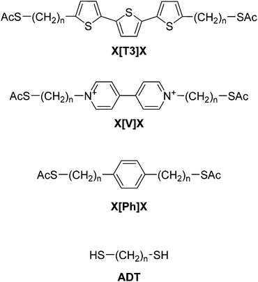 | ||
| Fig. 1 Structures and labelling of molecular systems discussed in this paper. X is the varying sidechain length (nCH2) and the nature of the central conjugated unit is abbreviated between brackets. | ||
Results and discussion
The series of molecular wires shown in Fig. 1 were synthesised and characterised using common synthetic laboratory techniques (see ESI‡ for synthetic procedures). The STM-based I(z) technique49 (details in the Methods section) was used to measure the conductance of the molecular wires presented in this work, and the more widely used STM-BJ technique11 was used as comparison for the most conductive molecular wire (more information in the ESI‡). In brief, a gold tip is moved towards a gold surface with a sub-monolayer of the target molecule and then retracted to yield current (I)–distance (z) traces that show a number of features characteristic of MMM junctions, such as steps and plateaux. Hundreds of such conductance–distance traces are collected and subsequently compiled in histograms bearing a distribution of conductance values. Peaks in the histograms were fitted to a Gaussian distribution to determine the most probable conductance, expressed in nS. Data for the X[Ph]X class of molecular wires was taken after Brooke et al.,41 and data for the alkanedithiol series was taken from Haiss et al.29 The experimentally determined conductance values were then plotted as ln(G) vs. length, and a linear fitting was used to obtain the β′ attenuation and its standard deviation is used as error.Example of results of single-molecule conductance measurements for the molecular wires capped with protected thiol functions are presented in Fig. 2a and b (see ESI‡ for further data), and the observed β′ decay is summarised in Fig. 2c and d. The X[T3]X series showed a very shallow conductance decay of 0.06 ± 0.01 Å−1 (0.07 ± 0.02 per methylene unit), more than one order of magnitude smaller than the value found in alkanedithiols. Measurements on X[Ph]X and X[V]X series gave a higher β′ value of 0.14 ± 0.02 Å−1 (0.17 ± 0.03 per methylene unit) and 0.39 ± 0.01 Å−1 (0.52 ± 0.01 per methylene unit), respectively. The X[V]X system has already been the subject of theoretical50 and experimental51 studies, and the published β′ value is slightly higher, at 0.59–0.61 Å−1 (0.66–0.76 per methylene unit). It must be noted, however, that these published values were obtained using the limited length interval from 5[V]5 to 8[V]8, while the data presented in this work spans a significantly larger interval (2[V]2 to 9[V]9). Previous results obtained from the X[V]X system47,52 have been interpreted with the Kuznetsov–Ulstrup model,53 a sequential two-channel mechanism due to non-resonant charge transport under electrochemical control. This model only applies when the system is “electrochemically tuned” such that molecular redox levels are in close energetic proximity to the contact Fermi levels. Under the open circuit conditions of the two-terminal measurements presented here, this is not the case and instead phase coherent tunnelling best describes the transport.
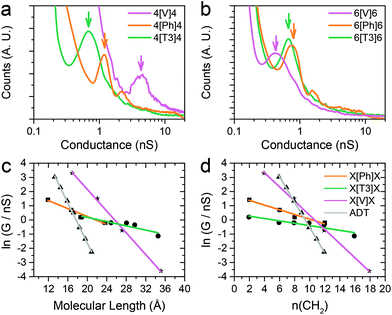 | ||
| Fig. 2 Examples of conductance histograms for (a) 4[X]4 and (b) 6[X]6. Data is displayed on a logarithmic scale, bin size 0.05 nS. Histograms are normalised to the total number of I(z) scans selected (791 for 4[V]4, 505 for 4[Ph]4, 592 for 4[T3]4, 640 for 6[V]6, 946 for 6[Ph]6 and 748 for 6[T3]6). ln(G) vs. length plots and linear fitting of data with (c) molecular length expressed in Å and (d) in number of methylene units in the sidechains. Molecular length is calculated as distance between two gold atoms tethered to the sulfur ends of the molecules in their lowest energy (all trans) conformation, using Wavefun Spartan® ‘14. All data recorded at 300 mV tip–substrate bias. See Fig. S1–S10 (ESI‡) for individual histograms. | ||
In order to explain the experimental data, we performed density functional theory – non-equilibrium Green's function (DFT-NEGF) theoretical calculations to model charge transport across the MMM junctions. To calculate the conductance of the junction consisting of two gold electrodes connected to the molecule, the optimal geometry and ground state Hamiltonian were obtained using SIESTA54 implementation of density functional theory and the room-temperature electrical conductance was calculated using the GOLLUM55 code (more details in the Methods section). The computed conductance G depends on the Fermi energy EF of the contacts, and since the value of EF relative to the frontier orbital energies of the molecule are not necessarily accurately predicted by DFT, in what follows we present results for G over a range of values of EF, centred on the DFT-predicted value of EF = 0.
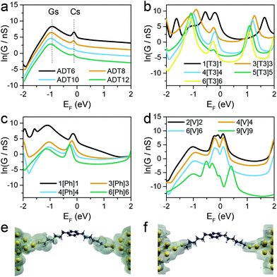
Fig. 3 shows the calculated conductance of the series of molecular wires, ADT for n(CH2) = 6, 8, 10 and 12 (Fig. 3a), X[T3]X where X = 1, 3, 4, 5 and 6 (Fig. 3b), X[Ph]X where X = 1, 3, 4 and 6 (Fig. 3c), and X[V]X where X = 2, 4, 6 and 9 (Fig. 3d). As shown in the conductance vs. Fermi energy plots for alkane dithiols (Fig. 3a), a broad resonance is present in the HOMO–LUMO gap, at about EF = −1 eV (labelled “Gs” in Fig. 3a). This feature has been previously assigned to “gateway” or “Au–S” states located on the sulfur anchors either by theoretical30,37,43 or spectroscopic means.56 Additional smaller but sharper resonances arise in our calculations very near to EF = 0 (labelled “Cs” in Fig. 3a), and we attribute these to the strong coupling between the two gateway states, through the molecular backbone (“coupling states”; see local density of states plots in Fig. 3e and f). These two features have already been discussed in the literature,42,43 and are present in all the calculations performed on the compounds presented in this study with thiol contacts, but their combined magnitude is more pronounced in the presence of central moieties comprising a α-terthiophene (Fig. 3b) or a phenyl ring (Fig. 3c) and, as shown in Fig. 4, they lead to a low β′ value for these molecules.
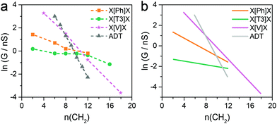 | ||
| Fig. 4 Comparison of experimental (a) and calculated (b) natural logarithm of conductance versus the number of methylene units in the side chains for the four series of molecular wires considered in this study. See Fig. S1–S10 (ESI‡) for individual histograms. | ||
Fig. 4b shows results for conductance values (G) obtained using the DFT-predicted Fermi energy and the slopes of these plots of ln(G) versus number of methylene units yields β′ for each molecular series. For direct comparison, the dash lines in Fig. 4a correspond to the experimental results. The values of the theoretical attenuation factors are: β′X[T3]X = 0.086, β′X[Ph]X = 0.20, β′X[V]X = 0.56 and βADT = 0.93 per methylene unit. It is then clear that the trends of the calculated β and β′ are in good agreement with the measured one. As shown in Fig. 4, in both theory and experiment the value of βADT > β′X[V]X > β′X[Ph]X > β′X[T3]X.
Since theory predicts that the low β′ values in X[Ph]X and X[T3]X are due to the transport through gateway/coupling states located on the sulfur atoms, we expect to dramatically increase the conductance attenuation if these states are removed. Thiomethyl (–SMe) groups interact with gold via a coordination bond between the metal orbitals and the lone pair localised on the sulfur atom, and the absence of a strong covalent bond should give no gateway or coupling states in the transmission curves. The calculated room-temperature conductance as function of energy is presented for X[Ph]X with thiol anchors in Fig. 5a and for X[Ph]X-SMe (with methyl thioether anchors on both sides) in Fig. 5b. As expected, in the presence of –SMe anchors there are no additional resonances in the HOMO–LUMO gap, and this results in a greatly increased value of β′.
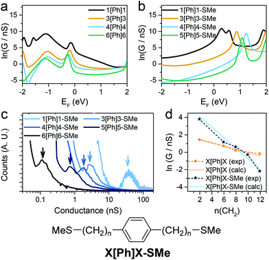 | ||
| Fig. 5 Calculated conductance of (a) Au-X[Ph]X-Au and (b) Au-X[Ph]X-SMe-Au at room temperature with predicted DFT-gap from Kohn–Sham mean field Hamiltonian. (c) Experimental X[Ph]X-SMe conductance histograms. Data is displayed on a logarithmic scale, bin size 0.01 nS. Histograms are normalised to the total number of I(z) scans selected (607 for 1[Ph]1-SMe, 656 for 3[Ph]3-SMe, 501 for 4[Ph]4-SMe, 566 for 5[Ph]5-SMe and 513 for 6[Ph]6-SMe). (d) Experimental and calculated conductance for X[Ph]X (orange) and X[Ph]X-SMe (blue) vs. number of CH2 units. Structure of the X[Ph]X-SMe system is shown for clarity. See Fig. S11–S15 (ESI‡) for individual histograms. | ||
To confirm the theoretical findings, we synthesised the series of molecular wires bearing a phenyl central unit and alkyl spacers of varying length with thiomethyl contacts (X[Ph]X-SMe), and measured their conductance (Fig. 5c). The results confirmed the theoretical prediction, with an increased attenuation factor β′ = 0.50 ± 0.04 Å−1 (0.56 ± 0.05 per methylene unit) upon removal of the gateway/coupling states (Fig. 5d). Thiomethyl is not the only contact group that increases the β′ value in these dialkyl benzene compounds, and an even higher value of >1 per methylene unit has been reported, for instance, in carboxylic acid-capped molecular wires.57
The role of these additional states can be further described from an analytical perspective, by using a simple theory which captures their effect in terms of two dimensionless parameters. In the low-voltage and low-temperature limit, the electrical conductance of a single molecule is given by
| G = G0T(EF) | (1) |
 is the quantum of conductance, EF is the Fermi energy of the electrodes and T(EF) is the transmission coefficient for electrons of energy EF passing from one electrode to the other, via the molecule. The transmission coefficient T(EF) is a property of the whole system comprising the leads, the molecule and the contact between the leads and the molecule. For example for the model structure sketched in Fig. 6a, in which electrons of energy EF pass through a single molecular orbital of energy E0, T(EF) is given by the Breit–Wigner formula1
 | (2) |
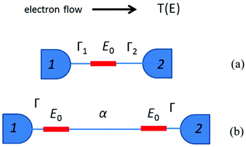 | ||
| Fig. 6 (a) A sketch of the model structure described by eqn (2), comprising a single molecular orbital connected to electrodes 1 and 2. (b) Model structure with two degenerate coupling orbitals of energy E0 connected to electrodes 1 and 2, and described by eqn (3). | ||
Now consider the case of a molecule containing two gateway orbitals of equal energy E0, coupled to each other by a tunnel barrier such as an alkyl chain represented by a tunnelling matrix element α, which decays exponentially with the length of the chain (Fig. 6b). Each of the orbitals is connected separately to electrodes 1 and 2. Since the energy spacing between these orbitals is zero (and therefore less than Γ1 + Γ2), eqn (1) cannot be used and the mathematical description of T(EF) is more complex (eqn (S1) in the ESI‡).58 For simplicity, we consider only the case of a symmetric junction, for which the formula of eqn (S)1 reduces to
| T(EF) = Af(εF,a) | (3) |
 .
.
Like eqn (2), this expression also involves two dimensionless parameters, namely a and εF. However, as shown in Fig. 7, unlike eqn (2), when plotted against εF, eqn (3) possesses two maxima when |a| > 1. These maxima occur at εF = ±(a2 − 1)1/2, which are associated with bonding and anti-bonding combinations of the two gateway orbitals, induced by the coupling α. Since α decreases with the length of the alkyl bridge, two maxima (the “coupling states”) are present for short molecules (i.e. for larger α) and merge into a single maximum for longer molecules. This splitting, for instance, also appears in DFT calculations of short ADT (Fig. S24 of the ESI‡).43
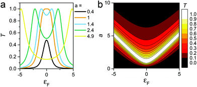 | ||
| Fig. 7 (a) Plots of eqn (3)versus εF for various values of a and (b) contour diagram of the right-hand side of eqn (3), where the coupling parameters a and εF are plotted as a function of T (colour bar). The splitting is evident in the contour plot for a > 1. | ||
Both the splitting and position of these maxima are sensitive to the length and conformation of the tunnelling bridge, and this length dependence is different for X[Ph]X compared with ADT, due to conformational changes induced by the presence of the phenyl ring in the latter. These overall variations of a, Γ, εF and T(EF) with the number of alkyl units leads to a steeper slope for ln![[thin space (1/6-em)]](https://www.rsc.org/images/entities/char_2009.gif) f(εF,a) in X[Ph]X, which cancels the trend in ln
f(εF,a) in X[Ph]X, which cancels the trend in ln![[thin space (1/6-em)]](https://www.rsc.org/images/entities/char_2009.gif) a, and decreases in the value of β′, in agreement with the experimental results and DFT calculations (further details on the parameters in section 8 of the ESI‡).
a, and decreases in the value of β′, in agreement with the experimental results and DFT calculations (further details on the parameters in section 8 of the ESI‡).
Conclusions
The above results demonstrate that when a conjugated central unit is sandwiched between two insulating alkyl chains the decay in conductance with the length of the chains is much shallower than that of alkyl chains alone. For example, the beta factor of an alkanedithiol is β = 0.9 Å−1, whereas in the presence of a phenyl ring central unit, this decreases to β′ = 0.18 Å−1 and in the presence of an α-terthiophene central unit, it further decreases to β′ = 0.07 Å−1. DFT and NEGF transport calculations demonstrated that this shallow length dependence is linked to charge transport assisted by additional states localised near the Au–S contact. To further investigate this phenomenon, we replaced the covalent-bonding thiol anchor with a coordination-bonding thiomethyl, which does not possess additional states near the Fermi energy. The predicted increase to β′ = 0.50 Å−1 for thiomethyl-terminated dialkylbenzene (X[Ph]X-SMe) molecular wires was confirmed experimentally. To underpin this new concept of gateway-driven conductance attenuation, we also introduced a simple model involving two dimensionless parameters, whose length dependence encapsulates these trends.Methods
Syntheses
Molecular wires used in this study were synthesised using common synthetic laboratory techniques. The syntheses of 6[T3]6![[thin space (1/6-em)]](https://www.rsc.org/images/entities/char_2009.gif) 59 and the two longest viologens (6[V]6 and 9[V]9) are described elsewhere.60 Synthetic procedures and characterisation data for previously unreported compounds are provided in the ESI.‡
59 and the two longest viologens (6[V]6 and 9[V]9) are described elsewhere.60 Synthetic procedures and characterisation data for previously unreported compounds are provided in the ESI.‡
Conductance measurements
The conductance of molecular junctions was determined using the STM I(z) technique as described previously in the literature.49,61 An adsorbed layer of the target molecule is formed on a flame-annealed gold-on-glass substrate (Arrandee Metal GmbH, DE – 250 nm Au, 2.5 nm Cr, 0.7 mm borosilicate glass) by immersion in a dilute (10−4 M) solution in CH2Cl2. The thioacetate moiety cleaves spontaneously in the presence of a Au substrate.62 The substrate is rinsed with copious ethanol to remove physisorbed molecules and dried under a stream of argon. An STM (former Molecular Imaging PicoSPM I, now 4500 SPM, Keysight Technologies Inc., USA) is used to drive an Au tip (Goodfellow Cambridge Ltd, UK – 99.99+%, 0.25 mm) close to the gold substrate at a defined setpoint current and under constant bias, so that junctions can form, and rapidly retracted (40 nm s−1), while a current (I) vs. distance (z) curve is recorded. The process is repeated many times, and hundreds of such junction making and breaking curves are analysed statistically in histograms to yield a distribution of conductance values. Spurious traces with no evidence of junction formation (plateaux and steps) were discarded to avoid ambiguity and reduce noise. The average hit rate (percentage of scans showing evidence of junction formation) is 10–15%, depending on the molecular wire. Plateaux in current–distance curves result in peaks in the histogram, and a Gaussian fit was used to determine the most probable conductance value.Theoretical calculations
The Hamiltonian of the structures described in this paper were obtained using density functional theory as described below or constructed from a simple tight-binding model with a single orbital per atom of site energy ε0 = 0 and nearest neighbour couplings γ = −1.DFT calculations
The optimized geometry and ground state Hamiltonian and overlap matrix elements of each structure was self-consistently obtained using the SIESTA54 implementation of DFT. SIESTA employs norm-conserving pseudo-potentials to account for the core electrons and linear combinations of atomic orbitals to construct the valence states. The generalized gradient approximation (GGA) of the exchange and correlation functional is used with the Perdew–Burke–Ernzerhof parameterization (PBE)63 a double-ζ polarized (DZP) basis set, a real-space grid defined with an equivalent energy cut-off of 250 Ry. The geometry optimization for each structure is performed to the forces smaller than 40 meV Å−1.Transport calculations
The mean-field Hamiltonian obtained from the converged DFT calculation or a simple tight-binding Hamiltonian was combined with our implementation of the non-equilibrium Green's function method, the GOLLUM55 code, to calculate the phase-coherent, elastic scattering properties of the each system consist of left (source) and right (drain) leads and the scattering region. The transmission coefficient T(E) for electrons of energy E (passing from the source to the drain) is calculated via the relation T(E) = Trace(ΓR(E)GR(E)ΓL(E)GR†(E)). In this expression, ΓL,R(E) = i(∑L,R(E) − ∑†L,R(E)) describe the level broadening due to the coupling between left (L) and right (R) electrodes and the central scattering region, ∑L,R(E) are the retarded self-energies associated with this coupling and
G
R = (ES − H − ∑L − ∑R)−1 is the retarded Green's function, where H is the Hamiltonian and S is the overlap matrix. Using the obtained transmission coefficient (T(E)), the conductance could be calculated by the Landauer formula  where G0 = 2e2/h is the conductance quantum, f(E) = (1 + exp((E − EF)/kBT))−1 is the Fermi–Dirac distribution function, T is the temperature and kB = 8.6 × 10⁻⁵ eV K−1 is the Boltzmann's constant.
Author contributions
S. J. H. and R. J. N. conceived the project. A. V., N. F., H. M. O. and L. B. synthesized the compounds and characterised them. A. V. and N. F. performed the STM measurements, and A. V. analysed the experimental data. S. S., H. S. and C. J. L. developed the theoretical explanation, and S. S. performed the calculations. S. J. H., C. J. L. and R. J. N. supervised the project. A. V. and S. S. wrote the manuscript. All authors discussed the results and commented on the manuscript.Conflicts of interest
The authors declare no competing financial interest.Acknowledgements
This work was supported by the UK EPSRC under grant EP/K001507/1 “Transition-edge sensors”, EP/H035818/1 and EP/H035184/1 “Medium effects in single-molecule electronics”, EP/J014753/1 “Ultra-high resolution, ultra-sensitive multifunctional ballistic nano sensors for the simultaneous detection of magnetic, electric and optical fields”, and EP/M005046/1 “Single-molecule photo-spintronics”. We also acknowledge support by the European Commission (EC) FP7 ITN “MOLESCO” network (project no. 606728).References
- C. J. Lambert, Chem. Soc. Rev., 2015, 44, 875–888 RSC
.
- H. Häkkinen, Nat. Chem., 2012, 4, 443–455 CrossRef PubMed
.
- W. Haiss, R. J. Nichols, H. van Zalinge, S. J. Higgins, D. Bethell and D. J. Schiffrin, Phys. Chem. Chem. Phys., 2004, 6, 4330–4337 RSC
.
- Y. Xing, T. Park, R. Venkatramani, S. Keinan, D. N. Beratan, M. J. Therien and E. Borguet, J. Am. Chem. Soc., 2010, 132, 7946–7956 CrossRef CAS PubMed
.
- W. Chen, J. R. Widawsky, H. Vázquez, S. T. Schneebeli, M. S. Hybertsen, R. Breslow and L. Venkataraman, J. Am. Chem. Soc., 2011, 133, 17160–17163 CrossRef CAS PubMed
.
- T. Hines, I. Díez-Pérez, H. Nakamura, T. Shimazaki, Y. Asai and N. Tao, J. Am. Chem. Soc., 2013, 135, 3319–3322 CrossRef CAS PubMed
.
- R. Frisenda, S. Tarkuç, E. Galán, M. L. Perrin, R. Eelkema, F. C. Grozema and H. S. J. van der Zant, Beilstein J. Nanotechnol., 2015, 6, 1558–1567 CrossRef CAS PubMed
.
- T. a. Su, J. R. Widawsky, H. Li, R. S. Klausen, J. L. Leighton, M. L. Steigerwald, L. Venkataraman and C. Nuckolls, J. Am. Chem. Soc., 2013, 135, 18331–18334 CrossRef CAS PubMed
.
- E. J. Dell, B. Capozzi, J. Xia, L. Venkataraman and L. M. Campos, Nat. Chem., 2015, 7, 209–214 CrossRef CAS PubMed
.
- Y. S. Park, A. C. Whalley, M. Kamenetska, M. L. Steigerwald, M. S. Hybertsen, C. Nuckolls and L. Venkataraman, J. Am. Chem. Soc., 2007, 129, 15768–15769 CrossRef CAS PubMed
.
- B. Xu and N. Tao, Science, 2003, 301, 1221–1223 CrossRef CAS PubMed
.
- P. Moreno-García, M. Gulcur, D. Z. Manrique, T. Pope, W. Hong, V. Kaliginedi, C. Huang, A. S. Batsanov, M. R. Bryce, C. Lambert and T. Wandlowski, J. Am. Chem. Soc., 2013, 135, 12228–12240 CrossRef PubMed
.
- G. Sedghi, V. M. García-Suárez, L. J. Esdaile, H. L. Anderson, C. J. Lambert, S. Martín, D. Bethell, S. J. Higgins, M. Elliott, N. Bennett, J. E. Macdonald and R. J. Nichols, Nat. Nanotechnol., 2011, 6, 517–523 CrossRef CAS PubMed
.
- D. J. Wold, R. Haag, M. A. Rampi and C. D. Frisbie, J. Phys. Chem. B, 2002, 106, 2813–2816 CrossRef CAS
.
- S. H. Choi, B. Kim and C. D. Frisbie, Science, 2008, 320, 1482–1486 CrossRef CAS PubMed
.
- S. H. Choi, C. Risko, M. C. R. Delgado, B. Kim, J.-L. Brédas and C. D. Frisbie, J. Am. Chem. Soc., 2010, 132, 4358–4368 CrossRef CAS PubMed
.
- G. Sedghi, K. Sawada, L. J. Esdaile, M. Hoffmann, H. L. Anderson, D. Bethell, W. Haiss, S. J. Higgins and R. J. Nichols, J. Am. Chem. Soc., 2008, 130, 8582–8583 CrossRef CAS PubMed
.
- Z. Li, T. Park, J. Rawson, M. J. Therien and E. Borguet, Nano Lett., 2012, 12, 2722–2727 CrossRef CAS PubMed
.
- Q. Ferreira, A. M. Bragança, L. Alcácer and J. Morgado, J. Phys. Chem. C, 2014, 118, 7229–7234 CAS
.
- C. Wang, A. S. Batsanov, M. R. Bryce, S. Martín, R. J. Nichols, S. J. Higgins, V. M. García-Suárez and C. J. Lambert, J. Am. Chem. Soc., 2009, 131, 15647–15654 CrossRef CAS PubMed
.
- V. Kolivoška, M. Valášek, M. Gál, R. Sokolová, J. Bulíčková, L. Pospíšil, G. Mészáros and M. Hromadová, J. Phys. Chem. Lett., 2013, 4, 589–595 CrossRef PubMed
.
- B. Q. Xu, X. L. Li, X. Y. Xiao, H. Sakaguchi and N. J. Tao, Nano Lett., 2005, 5, 1491–1495 CrossRef CAS PubMed
.
- B. Capozzi, E. J. Dell, T. C. Berkelbach, D. R. Reichman, L. Venkataraman and L. M. Campos, J. Am. Chem. Soc., 2014, 136, 10486–10492 CrossRef CAS PubMed
.
- R. Yamada, H. Kumazawa, T. Noutoshi, S. Tanaka and H. Tada, Nano Lett., 2008, 8, 1237–1240 CrossRef CAS PubMed
.
- E. Leary, H. Höbenreich, S. J. Higgins, H. van Zalinge, W. Haiss, R. J. Nichols, C. Finch, I. Grace, C. J. Lambert, R. McGrath and J. Smerdon, Phys. Rev. Lett., 2009, 102, 86801 CrossRef CAS PubMed
.
- H. Yan, A. Johan, R. L. Mccreery, M. Luisa, D. Rocca, P. Martin, P. Lafarge and J. Christophe, Proc. Natl. Acad. Sci. U. S. A., 2013, 110, 5326–5330 CrossRef CAS PubMed
.
- X. Li, J. He, J. Hihath, B. Xu, S. M. Lindsay and N. Tao, J. Am. Chem. Soc., 2006, 128, 2135–2141 CrossRef CAS PubMed
.
- E. Pires, J. E. Macdonald and M. Elliott, Nanoscale, 2013, 5, 9397–9403 RSC
.
- W. Haiss, S. Martin, L. E. Scullion, L. Bouffier, S. J. Higgins and R. J. Nichols, Phys. Chem. Chem. Phys., 2009, 11, 10831–10838 RSC
.
- C. Li, I. Pobelov, T. Wandlowski, A. Bagrets, A. Arnold and F. Evers, J. Am. Chem. Soc., 2008, 130, 318–326 CrossRef CAS PubMed
.
- Z. Xie, I. Bâldea, S. Oram, C. E. Smith and C. D. Frisbie, ACS Nano, 2017, 11, 569–578 CrossRef CAS PubMed
.
- K. Wang, J. Hamill, J. Zhou, C. Guo and B. Q. Xu, Faraday Discuss., 2014, 174, 91–104 RSC
.
- J. Hihath and N. J. Tao, Semicond. Sci. Technol., 2014, 29, 54007 CrossRef
.
- C. Jia and X. Guo, Chem. Soc. Rev., 2013, 42, 5642–5660 RSC
.
- Y. Selzer, M. A. Cabassi, T. S. Mayer and D. L. Allara, J. Am. Chem. Soc., 2004, 126, 4052–4053 CrossRef CAS PubMed
.
- M. L. Perrin, R. Frisenda, M. Koole, J. S. Seldenthuis, J. a C. Gil, H. Valkenier, J. C. Hummelen, N. Renaud, F. C. Grozema, J. M. Thijssen, D. Dulić and H. S. J. van der Zant, Nat. Nanotechnol., 2014, 9, 830–834 CrossRef CAS PubMed
.
- W. B. Chang, C.-K. Mai, M. Kotiuga, J. B. Neaton, G. C. Bazan and R. A. Segalman, Chem. Mater., 2014, 26, 7229–7235 CrossRef CAS
.
- Y. Geng, S. Sangtarash, C. Huang, H. Sadeghi, Y. Fu, W. Hong, T. Wandlowski, S. Decurtins, C. J. Lambert and S. X. Liu, J. Am. Chem. Soc., 2015, 137, 4469–4476 CrossRef CAS PubMed
.
- S. Sangtarash, C. Huang, H. Sadeghi, G. Sorohhov, J. Hauser, T. Wandlowski, W. Hong, S. Decurtins, S.-X. Liu and C. J. Lambert, J. Am. Chem. Soc., 2015, 137, 11425–11431 CrossRef CAS PubMed
.
- S. Sangtarash, H. Sadeghi and C. J. Lambert, Nanoscale, 2016, 8, 13199–13205 RSC
.
- C. Brooke, A. Vezzoli, S. J. Higgins, L. A. Zotti, J. J. Palacios and R. J. Nichols, Phys. Rev. B: Condens. Matter Mater. Phys., 2015, 91, 195438 CrossRef
.
- Y. Kim, T. J. Hellmuth, M. Bürkle, F. Pauly and E. Scheer, ACS Nano, 2011, 5, 4104–4111 CrossRef CAS PubMed
.
- F. Hüser and G. C. Solomon, J. Phys. Chem. C, 2015, 119, 14056–14062 Search PubMed
.
- J. R. Widawsky, W. Chen, H. Vázquez, T. Kim, R. Breslow, M. S. Hybertsen and L. Venkataraman, Nano Lett., 2013, 13, 2889–2894 CrossRef CAS PubMed
.
- Z. Xie, I. Bâldea, C. E. Smith, Y. Wu and C. D. Frisbie, ACS Nano, 2015, 9, 8022–8036 CrossRef CAS PubMed
.
- E. Leary, S. J. Higgins, H. van Zalinge, W. Haiss and R. J. Nichols, Chem. Commun., 2007, 38, 3939 RSC
.
- E. Leary, S. J. Higgins, H. van Zalinge, W. Haiss, R. J. Nichols, S. Nygaard, J. O. Jeppesen and J. Ulstrup, J. Am. Chem. Soc., 2008, 130, 12204–12205 CrossRef CAS PubMed
.
- P. Stipa, Spectrochim. Acta, Part A, 2006, 64, 653–659 CrossRef PubMed
.
- W. Haiss, H. van Zalinge, S. J. Higgins, D. Bethell, H. Höbenreich, D. J. Schiffrin and R. J. Nichols, J. Am. Chem. Soc., 2003, 125, 15294–15295 CrossRef CAS PubMed
.
- A. Bagrets, A. Arnold and F. Evers, J. Am. Chem. Soc., 2008, 130, 9013–9018 CrossRef CAS PubMed
.
- Z. Li, I. Pobelov, B. Han, T. Wandlowski, A. Błaszczyk and M. Mayor, Nanotechnology, 2007, 18, 44018 CrossRef
.
- I. V. Pobelov, Z. Li and T. Wandlowski, J. Am. Chem. Soc., 2008, 130, 16045–16054 CrossRef CAS PubMed
.
- A. M. Kuznetsov and J. Ulstrup, J. Phys. Chem. A, 2000, 104, 11531–11540 CrossRef CAS
.
- J. M. Soler, E. Artacho, J. D. Gale, A. García, J. Junquera, P. Ordejón and D. Sánchez-Portal, J. Phys.: Condens. Matter, 2002, 14, 2745–2779 CrossRef CAS
.
- J. Ferrer, C. J. Lambert, V. M. García-Suárez, D. Z. Manrique, D. Visontai, L. Oroszlany, R. Rodríguez-Ferradás, I. Grace, S. W. D. Bailey, K. Gillemot, H. Sadeghi and L. a Algharagholy, New J. Phys., 2014, 16, 93029 CrossRef
.
- A. Xiang, M. Wang, H. Wang, H. Sun, S. Hou and J. Liao, Chem. Phys., 2016, 465–466, 40–45 CrossRef CAS
.
- Z. W. Hong, M. A. Ben Aissa, L. L. Peng, H. Xie, D. L. Chen, J. F. Zheng, Y. Shao, X. S. Zhou, N. Raouafi and Z. J. Niu, Electrochem. Commun., 2016, 68, 86–89 CrossRef CAS
.
- L. Oroszlány, A. Kormányos, J. Koltai, J. Cserti and C. J. Lambert, Phys. Rev. B: Condens. Matter Mater. Phys., 2007, 76, 45318 CrossRef
.
- A. Vezzoli, I. Grace, C. Brooke, K. Wang, C. J. Lambert, B. Q. Xu, R. J. Nichols and S. J. Higgins, Nanoscale, 2015, 7, 18949–18955 RSC
.
- W. Haiss, R. J. Nichols, S. J. Higgins, D. Bethell, H. Höbenreich and D. J. Schiffrin, Faraday Discuss., 2004, 125, 179–194 RSC
.
- R. J. Nichols, W. Haiss, S. J. Higgins, E. Leary, S. Martin and D. Bethell, Phys. Chem. Chem. Phys., 2010, 12, 2801–2815 RSC
.
- A. Singh, D. H. Dahanayaka, A. Biswas, L. A. Bumm and R. L. Halterman, Langmuir, 2010, 26, 13221–13226 CrossRef CAS PubMed
.
- J. P. Perdew, K. Burke and M. Ernzerhof, Phys. Rev. Lett., 1996, 77, 3865–3868 CrossRef CAS PubMed
.
Footnotes |
| † Data collected using EPSRC funding at Liverpool are archived at http://datacat.liverpool.ac.uk/id/eprint/198 or at DOI 10.17638/datacat.liverpool.ac.uk/198. |
| ‡ Electronic supplementary information (ESI) available: Synthetic procedures, single-molecule conductance measurements, additional theoretical details and calculations, 1H and 13C NMR Spectra. See DOI: 10.1039/c7nr07243k |
| § These authors contributed equally to this work. |
| ¶ Current address for Laurent Bouffier: Université de Bordeaux, ISM, CNRS, UMR 5255, Bordeaux INP, F-33400 Talence, France. |
| This journal is © The Royal Society of Chemistry 2018 |

