Tetraphenylpyrazine-based luminogens with full-colour emission†
Lingxiang
Pan
a,
Yuanjing
Cai
 a,
Haozhong
Wu
a,
Fan
Zhou
a,
Anjun
Qin
a,
Haozhong
Wu
a,
Fan
Zhou
a,
Anjun
Qin
 *a,
Zhiming
Wang
*a and
Ben Zhong
Tang
*ab
aState Key Laboratory of Luminescent Materials and Devices, Center for Aggregation-Induced Emission, South China University of Technology, Guangzhou 510640, China. E-mail: msqinaj@scut.edu.cn; wangzhiming@scut.edu.cn
bDepartment of Chemistry, Hong Kong Branch of Chinese National Engineering Research Center for Tissue Restoration and Reconstruction, The Hong Kong University of Science & Technology, Clear Water Bay, Kowloon, Hong Kong, China. E-mail: tangbenz@ust.hk
First published on 19th March 2018
Abstract
Aggregation-induced emission (AIE) has become a hot research topic. The generation of new AIE luminogens (AIEgens) will further promote the development of the AIE area. Currently, AIEgens with different emission colours have been reported. However, full-colour emissive luminogens based on a single AIE core and the structure–property relationship are rarely reported. To tackle this challenge, in this work, six tetraphenylpyrazine (TPP)-based luminogens DTPP, DTPP-Ph, DTPP-BT, DTPP-T, DTPP-TO and DTPP-TBTT are rationally designed by varying the effective conjugation and donor–acceptor units and facilely prepared under mild reaction conditions. The photophysical property investigation shows that they exhibit bright blue to red emission in the film states, covering the whole visible light range. Through systematic experimental investigations and theoretical calculations, their structure–photophysical property, and the competition of restriction of intramolecular motion and intramolecular charge-transfer are unambiguously elaborated. Moreover, DTPP-BT can be used as a reversible mechanochromic material and an indicator to show the exciton recombination area in OLEDs. This work provides guidance for further design of AIEgens with high efficiency and full-colour emission from a single AIE core.
Introduction
Recent years have witnessed the rapid development of organic light-emitting diodes (OLEDs) in full-colour display and white light emission. Efficient organic full-colour light-emitting materials are in great demand.1 However, most traditional organic fluorophores are highly emissive in dilute solutions, and their emission is weakened or totally quenched in the aggregate or solid state. In other words, these fluorophores suffer from the aggregation-caused quenching (ACQ) effect, which has become a thorny obstacle for their high-tech applications.2 To avoid the negative ACQ effect, chemical, physical and engineering approaches have been adopted. However, limited success has been achieved due to the natural process of molecular aggregation.3Instead of fighting against the molecular aggregation in enhancing the emission of fluorophores, we found that molecular aggregation can enhance the emission of luminogens in 2001. Propeller-shaped molecules, such as siloles, are non-emissive in dilute solutions but remarkably emissive upon the formation of aggregates or fabrication into solid films. Accordingly, we termed this unique phenomenon as “aggregation-induced emission (AIE)”.2a–c,4–12 Through systematic experimental investigations and theoretical simulation, restriction of intramolecular motion (RIM),10 including restriction of intramolecular rotation (RIR)2a,11 and restriction of intramolecular vibration (RIV),12 has been rationalized as the mechanism of AIE. Under this guidance, many AIE cores, like silole,5 tetraphenylethylene (TPE),6 distyrylanthracene (DSA),7 tetraphenylbenzene,8a tetraphenylpyrrole,8b multiphenyl substituted 1,3-butadiene8c and others,9 have been prepared and applied in optoelectronics, sensing, and biological fields.
Recently, we made progress in developing another AIE core, namely tetraphenylpyrazine (TPP), which combines the advantages of TPE's facile preparation and silole's high thermal stability.13 Moreover, thanks to its easy functionalization, various substitutes have been attached to TPP and versatile properties have been realized. For example, the triphenylamine-modified TPP derivative shows high performance as an emitting layer in OLED application owing to its low electron affinity and good electron injection ability.14 By combining its aforementioned advantages, in this paper, we further developed TPP-based luminogens and widened their emission from the ultraviolet region at 390 nm to the whole visible light by tuning the conjugation and attaching the electron-donating groups, such as thienyl and phenyl groups, and/or electron-accepting groups, such as benzothiadiazole (BT) and thienyl dioxide (TO), where the intramolecular charge transfer (ICT) will readily occur and in turn the emission is red-shifted (Scheme 1). The strategy in this work provides guidance for designing highly efficient and full-colour emissive luminogens based on other AIE cores.
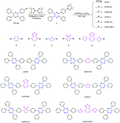 | ||
| Scheme 1 Synthetic routes to TPP derivatives of DTPP, DTPP-Ph, DTPP-BT, DTPP-T, DTPP-TO and DTPP-TBTT. | ||
Results and discussion
Synthesis
The TPP derivatives of DTPP, DTPP-Ph, DTPP-BT, DTPP-T, DTPP-TO and DTPP-TBTT were facilely prepared according to the routes shown in Scheme 1 (the detailed synthetic procedures and characterization data are given in the ESI†). The key intermediate of 1 was synthesized by the reaction of TPP-Br,14,15 and bis(pinacolato)diboron in a yield of 89.7%. Then, 1 was subjected to react with TPP-Br or dibromo-substituted compounds of 2, 3, 4, 5 and 6 in the presence of the catalyst of Pd(PPh3)4, and DTPP, DTPP-Ph, DTPP-BT, DTPP-T, DTPP-TO and DTPP-TBTT were readily generated, respectively. These TPP derivatives were fully characterized by NMR spectroscopy and high resolution mass spectroscopy, and satisfactory results corresponding to their structures were obtained (Fig. S1–S20, ESI†). Moreover, these compounds are soluble in commonly used organic solvents, such as dichloromethane, chloroform, and tetrahydrofuran (THF), but insoluble in water. They are also thermally stable. As shown in Fig. S21A (ESI†), the temperatures of 5% weight loss of DTPP, DTPP-Ph, DTPP-BT, DTPP-T and TPP-TBTT are as high as 402, 442, 496, 476 and 526 °C, respectively, whereas TPP-TO begins to lose its weight at a temperature of 240 °C probably due to the decomposition of thiophene dioxide. Moreover, their glass transition temperatures (Tg) were also measured (Fig. S21B, ESI†). We cannot observe the Tg of DTPP and DTPP-TO during the testing process, whereas those of the others were recorded ranging from 146 to 175 °C, implying that they exhibit enough morphological stability in OLED application.Photophysical properties
According to our design strategy, these luminogens should emit light covering the whole visible wavelength range. Indeed, the powders of these TPP derivatives emit blue to red light upon irradiation with a UV lamp (Fig. 1). Since this is the first time to realize the full-colour emission of TPP-based luminogens, we systematically investigate their photophysical properties. | ||
| Fig. 1 Photos of DTPP, DTPP-Ph, DTPP-BT, DTPP-T, DTPP-TO and DTPP-TBTT in amorphous powders, taken under the illumination of (A) a daylight lamp and (B) an UV lamp (365 nm). | ||
Fig. 2A shows the absorption spectra of these TPP-based luminogens in THF. DTPP, DTPP-Ph and DTPP-T have similar absorption profiles with peaks at 353, 354 and 385 nm, respectively, while those of DTPP-BT, DTPP-TO and DTPP-TBTT exhibit two absorption peaks with longer wavelengths at 403, 426 and 508 nm, respectively. This difference could be ascribed to ICT process. Although TPP has been proven to be an electron-withdrawing group in our previous work,14a no peaks associated with ICT were found when the phenyl or thienyl group was inserted between two TPP units, which is probably due to the structural symmetry. However, when strong electron-accepting groups, such as BT, TO and thienyl–BT–thienyl, are inserted, the ICT process readily occurred, in which the TPP unit might serve as an electron-donating group. These results suggest that TPP might be potentially used as a bipolar moiety.
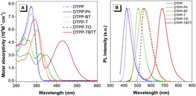 | ||
| Fig. 2 (A) Absorption of THF solutions (10 μM) and (B) photoluminescence spectra of films of DTPP, DTPP-Ph, DTPP-BT, DTPP-T, DTPP-TO and DTPP-TBTT. | ||
Next, the photoluminescence (PL) spectra of these luminogens were measured to further distinguish their difference in the ICT process. The results show that these luminogens emit in the range of 430–612 nm in THF (Table 1, Fig. 2B and Fig. S22, ESI†). Interestingly, the emission of DTPP-T, DTPP-TO and DTPP-TBTT in solutions is remarkably red-shifted compared to those in films, whereas little change was found in the others.
| Compound | λ abs | λ em /nm | Φ F /% | τ /ns | K r (107 s−1) | K nr (107 s−1) | |||||
|---|---|---|---|---|---|---|---|---|---|---|---|
| Soln | Film | Soln | Film | Soln | Film | Soln | Film | Soln | Film | ||
| a Maximum absorption wavelength, concentration: 10 μM. b Maximum emission wavelength, soln: THF solution, film: droplet film. c Absolute fluorescence quantum efficiency. d Fluorescence lifetime. e K r = ΦF/τ. f K nr = (1 − ΦF)/τ. | |||||||||||
| DTPP | 353 | 430 | 418 | 0.9 | 16.9 | 0.41 | 0.53 | 2.2 | 31.9 | 241.7 | 156.8 |
| DTPP-Ph | 354 | 434 | 436 | 1.0 | 28.3 | 0.41 | 0.55 | 2.4 | 51.5 | 241.5 | 130.4 |
| DTPP-BT | 340, 403 | 509 | 506 | 79.5 | 62.1 | 3.19 | 1.81 | 24.9 | 34.3 | 6.4 | 20.9 |
| DTPP-T | 385 | 455 | 546 | 36.5 | 21.7 | 0.67 | 0.84 | 54.5 | 25.8 | 94.8 | 93.2 |
| DTPP-TO | 341, 426 | 529 | 552 | 55.2 | 33.3 | 1.98 | 1.47 | 27.9 | 22.7 | 22.6 | 45.4 |
| DTPP-TBTT | 370, 508 | 612 | 680 | 66.1 | 13.0 | 5.26 | 3.66 | 12.6 | 3.6 | 6.4 | 23.8 |
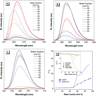
TPP is a good AIEgen. Are TPP-based luminogens also AIE active? To answer this question, we investigated their emission behaviours in THF/water mixtures with different water fractions (fw) (Fig. 3 and Fig. S23, ESI†). The results show that DTPP and DTPP-Ph are weakly emissive in THF but their emission is greatly intensified in THF/water mixtures with fw of more than 50%, exhibiting typical aggregation-enhanced emission (AEE) characteristics. Interestingly, as shown in Fig. 3A, with fw from 0 to 80%, the emission peaks of DTPP in THF/water mixtures are blue-shifted from 430 to 421 nm. This phenomenon could be attributed to the formation of nanocrystals as generally observed in TPE-based systems,16 while the others exhibit a typical ACQ effect. The absolute quantum yields (ΦF) also confirm the PL measurements. As shown in Table 1, AEE-active DTPP and DTPP-Ph possess quite low ΦF (∼1%) in THF solutions; however, the values greatly increase to 16.9 and 28.3% in their film states, respectively. The others show high ΦF in solutions, but the values decrease upon fabrication into thin films.
These results indicate that for DTPP and DTPP-Ph, the RIM process plays a crucial role in intensifying the emission in the aggregate and film states, whereas for DTPP-BT, DTPP-TO, and DTPP-TBTT, both RIM and ICT processes affect their emission behaviours, and the latter is much stronger than the former. In addition, the ACQ effect of DTPP-T that contains no strong electron-accepting but donating thienyl group might be probably due to the planarization of the structure, which is proved by the red-shifted emission in solution compared to that in the film state.
In order to further understand the photophysical properties of these TPP-based luminogens, their time-resolved fluorescence was measured in THF solution and film states (Fig. S24, ESI†), and the radiative and non-radiative decay rates were calculated and are listed in Table 1. Generally, the RIM process would lead to the decrease of non-radiative decay rate (Knr). Thus, this parameter is used to check the occurrence of the RIM process.
Compared with the transition rates in solution, the radiative decay rates (Kr) of DTPP and DTPP-Ph in the film state become much larger. At the same time, the values of Knr decrease. These data imply that the improvement in the fluorescence efficiency of DTPP and DTPP-Ph could be ascribed to the RIM process. For DTPP-TO and DTPP-TBTT, the Kr values become smaller, while the Knr values increase, indicating that the RIM effect on the improved efficiency is far less than that of the ICT process. As a result, they suffer from the ACQ effect. In addition, as a special example, both Kr and Knr values of DTPP-BT in the film state become larger simultaneously than those in the solution state, suggesting that the RIM and ICT processes are all active, and the effect of the latter is a little stronger than that of the former. Moreover, for DTPP-T, both Kr and Knr values decrease from the solution to film state, and the decrease of Kr is much faster than that of Knr, which leads to the quenching of its fluorescence.
Theoretical calculations
We also studied the intrinsic photophysical processes of these TPP-based luminogens using density function theory (DFT) of B3LYP with the 6-31G(d) basis set. As shown in Fig. 4 and Table 2, the dihedral angles of periphery phenyl rings connected with the pyrazine cores are around 36° in the optimized TPP-based luminogens. This structural configuration is beneficial for obstructing the intermolecular π–π stacking and improving fluorescence efficiency in the aggregate state via the RIM process.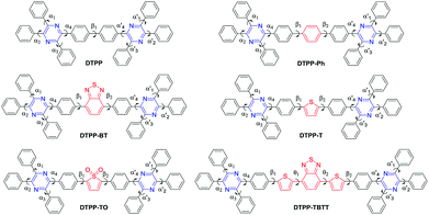 | ||
| Fig. 4 The marks of the twisting angles in the optimized molecular structures of DTPP, DTPP-Ph, DTPP-BT, DTPP-T, DTPP-TO and DTPP-TBTT. | ||
| Luminogens | Twisting anglea (°) | |||||||||||
|---|---|---|---|---|---|---|---|---|---|---|---|---|
| α 1 | α 2 | α 3 | α 4 | α 1′ | α 2′ | α 3′ | α 4′ | β 1 | β 2 | θ 1 | θ 2 | |
| a The marks of the twist angles are shown in Fig. 4. | ||||||||||||
| DTPP | 36.00 | 35.62 | 36.26 | 34.78 | 35.62 | 36.00 | 36.26 | 34.78 | 35.47 | |||
| DTPP-Ph | 35.95 | 35.84 | 36.05 | 35.11 | 35.92 | 35.83 | 36.29 | 34.62 | 35.93 | 35.26 | ||
| DTPP-BT | 36.04 | 35.53 | 36.28 | 34.80 | 35.88 | 35.50 | 35.91 | 35.11 | 34.74 | 34.61 | ||
| DTPP-T | 36.30 | 35.90 | 36.20 | 34.53 | 33.74 | 36.29 | 36.20 | 34.53 | 20.86 | 20.86 | ||
| DTPP-TO | 35.81 | 35.27 | 35.85 | 34.46 | 35.94 | 35.30 | 36.47 | 34.56 | 22.64 | 19.97 | ||
| DTPP-TBTT | 36.38 | 35.57 | 36.46 | 33.75 | 36.26 | 35.30 | 36.36 | 33.55 | 21.09 | 23.50 | 4.90 | 7.58 |
However, the distribution of HOMOs and LUMOs in their molecular structures is quite different (Fig. 5). For DTPP and DTPP-Ph, their HOMOs and LUMOs are almost located on the whole molecules, suggesting that the RIM process is a potential and key factor in influencing radiation transition behaviors. Meanwhile, the ICT process is negligible for DTPP and DTPP-Ph. Thus, we can draw a conclusion that the AEE feature of these two luminogens is due to the RIM process.
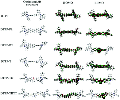 | ||
| Fig. 5 Optimized molecular conformation and molecular orbital amplitude plots of HOMO and LUMO energy levels of DTPP, DTPP-Ph, DTPP-BT, DTPP-T, DTPP-TO and DTPP-TBTT. | ||
For DTPP-TO and DTPP-TBTT, obvious ICT processes take place and a small amount of electron clouds are located on the periphery phenyl rings. These results suggest that the PL is dominated by the ICT process and RIM plays a less important role. Hence, the ΦF values of DTPP-TO and DTPP-TBTT decrease from the solution to film state. Similarly, a small amount of electron clouds are located on the periphery phenyl rings of DTPP-T as shown in Fig. 5. As a result, no obvious ICT process is observed. However, the planar central structure of phenyl–thienyl–phenyl moieties might facilitate the intermolecular interactions in the aggregate state, which leads to the decrease in its emission. This conclusion could well explain its aforementioned absorption and emission behaviours.
Meanwhile, for DTPP-BT, the distribution of the HOMO and LUMO implies the presence of the ICT process like DTPP-TBTT. In addition, the electron clouds in the HOMO are also partially located on the periphery phenyl rings like DTPP. These results suggest that both RIM and ICT processes influence its emission in the aggregate state. The balance of these two competitive processes makes DTPP-BT highly emissive both in solution and film states.17
Mechanochromic properties
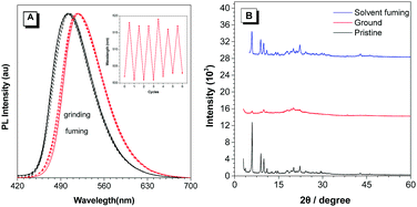
Among the prepared TPP-based luminogens, DTPP-BT displays fluorescent mechanochromic behaviour. As shown in Fig. 7, the as-prepared green emissive powder peaked at 502 nm could be converted to a yellow emissive one with peak shifted to 518 nm upon grinding using a pestle. Thus, the characters of “AIE” could be clearly seen if written by the pestle. When fuming the yellow emissive powder with CH2Cl2, it readily recovered to the green emission. Moreover, this change is reversible without distinct waveform variations of the two states (Fig. 8A). The powder X-ray diffraction (PXRD) technique was used to reveal the reason for the mechanochromic behaviour of DTPP-BT, and the results indicate that this phenomenon occurs due to the change in molecular packing modes.6b As shown in Fig. 8B, the diffraction patterns of the as-prepared and the solvent fumed powders clearly exhibit sharp and intense reflections, indicating DTPP-BT form microcrystals. In contrast, the ground powders do not exhibit any noticeable diffraction in the PXRD profile, reflecting its amorphous feature.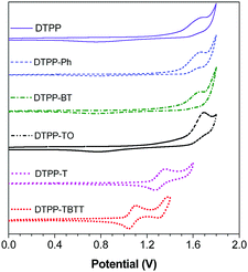 | ||
| Fig. 6 Cyclic voltammograms of DTPP, DTPP-Ph, DTPP-BT, DTPP-T, DTPP-TO and DTPP-TBTT, measured in dichloromethane containing 0.1 M tetra-n-butylammonium hexafluorophosphate, scan rate: 100 mV s−1. | ||
 | ||
| Fig. 7 Photographs of DTPP-BT in the pristine state and its ground or solvent fuming samples under a UV lamp. | ||
Electrochemical properties
Cyclic voltammetry (CV) measurements were carried out to evaluate the practical energy levels of these TPP-based luminogens. The onset potentials of DTPP, DTPP-Ph, DTPP-BT, DTPP-T, DTPP-TO and DTPP-TBTT were deduced to be 1.34, 1.41, 1.38, 1.15, 1.45 and 0.93 eV, respectively (Fig. 6). The HOMO energy levels are estimated from the onset oxidation potentials according to the equation: HOMO = −(4.4 + Eonset) eV, and the LUMO energy levels (LUMO = HOMO + Eg) are determined by the optical band gaps (Eg = 1240/λonset, where the λonset is calculated by onset absorption).6d,16,17 The HOMO energy levels were thus calculated to be −5.74, −5.81, −5.78, −5.55, −5.85 and −5.33 eV, and the LUMO energy levels are −2.61, −2.68, −3.08, −2.73, −3.35 and −3.26 eV for DTPP, DTPP-Ph, DTPP-BT, DTPP-T, DTPP-TO and DTPP-TBTT, respectively (Table S1, ESI†). The LUMO energy levels of these TPP-based luminogens are close to or even lower than those of the widely used electron-transporting materials, such as Alq3 (−3.0 eV)18 and TPBi (−2.7 eV),19 suggesting that they are promising candidates for OLED application.Electroluminescence (EL)
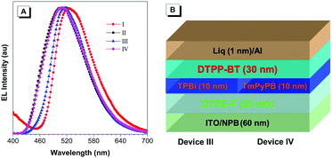
Thanks to the balance between the RIM and ICT processes of DTPP-BT, it shows a high ΦF of 62.1% in the film state. We thus used it as an emitting layer to fabricate the non-doped OLED with the device configuration of ITO/NPB (60 nm)/DTPP-BT (20 nm)/TPBi (40 nm)/LiF (1 nm)/Al (device I), where N,N-bis(1-naphthyl)-N,N-diphenylbenzidine (NPB) serves as the hole-transporting layer, 2,2′,2′′-(1,3,5-benzinetriyl)tris-(1-phenyl-1-H-benzimidazole) (TPBi) works as the electron-transporting layer, and LiF functions as the electron-injecting layer.20 As shown in Fig. 9 and Table 3 (for details, please refer to Fig. S25, ESI†), device I exhibits green EL at 520 nm with Commission International d’Eclairage (CIE) chromaticity coordinates of (0.319, 0.543). The maximum luminance (Lmax), power (ηP,max), current (ηC,max), and external quantum (ηext,max) efficiencies of device I were measured to be 3173 cd m−2, 0.77 lm W−1, 1.25 cd A−1, and 0.4%, respectively. To explain the relatively low performance of device I, a more precise LUMO value of DTPP-BT was estimated from the reduction potential in the CV curve (Fig. S26, ESI†), and this value was deduced to be −3.38 eV, which is lower than the one determined from the optical band gap (−3.08 eV). By comparison, DTPP-TBTT and DTPP-TO were measured under the same conditions, and the values were calculated at −3.39 eV and −3.50 (Fig. S26, ESI†). The difference between optical band gaps and electro band gaps of these luminogens might originate from their stronger donor–acceptor conjugation effect. This explanation is further confirmed by the red-shifted EL emission of DTPP-BT from its film (506 nm) to device (520 nm). The more accurate LUMO value also provides a more reasonable explanation for the lower OLED performance.| Device | λ EL (nm) | V on (V) | L (cd m−2) | η C (cd A−1) | η P (lm W−1) | EQEf (%) | CIE (x, y)g |
|---|---|---|---|---|---|---|---|
| a λ EL = EL maximum. b V on = turn-on voltage at 1 cd m−2. c L max = maximum luminance. d η c,max = maximum current efficiency. e η P,max = maximum power efficiency. f η ext,max = maximum external quantum efficiency. g CIE = Commission International de I’Eclairage coordinates. | |||||||
| I | 520 | 3.8 | 3173 | 1.25 | 0.77 | 0.40 | (0.319, 0.543) |
| II | 508 | 3.3 | 24298 | 9.98 | 7.02 | 3.67 | (0.244, 0.435) |
| III | 518 | 3.8 | 8235 | 3.89 | 3.21 | 1.26 | (0.276, 0.545) |
| IV | 508 | 4.2 | 4250 | 1.34 | 1.00 | 0.49 | (0.252, 0.442) |
Meanwhile, the low LUMO energy level of DTPP-BT makes it potentially useful as electron-modified layer. To confirm this hypothesis, we adopted tetraphenylethylene-furan (TPE-F), our previously reported AIEgen from which excellent device performance was achieved (device II in this paper),21 as an emitting layer, DTPP-BT as an electron-injecting/transporting layer, and TPBi or 1,3,5-tri[(3-pyridyl)-phen-3-yl]benzene (TmPyPB) as a hole-blocking layer to fabricate devices (III and IV). Device III (configuration: ITO/NPB (60 nm)/DTPE-F (20 nm)/TPBi (10 nm)/DTPP-BT (30 nm)/LiF (1 nm)/Al) and device IV (configuration: ITO/NPB (60 nm)/DTPE-F (20 nm)/TmPyPB(10 nm)/DTPP-BT (30 nm)/LiF (1 nm)/Al) exhibit good performance with bright green emission as shown in Table 3. However, the areas of exciton recombination in devices III and IV are different as indicated by their EL peaks. In device III, the EL is peaked at around 518 nm, which is similar to that of device I, implying that the exciton recombination area might be in the DTPP-BT layer instead of the emitting layer. In device IV, the EL emission is peaked at 508 nm, which is similar with that of device II, suggesting that the exciton recombination area is in the emitting layer.
Since the difference of devices III and IV is mainly in the hole-blocking layer of TPBi and TmPyPB, these results indicate that DTPP-BT could be used as an indicator to show the exciton recombination area and estimate the hole blocking capability of some electron-modified materials.
Conclusion
In this paper, six TPP-based luminogens DTPP, DTPP-Ph, DTPP-BT, DTPP-T, DTPP-TO, DTPP-TBTT were rationally designed via tuning their conjugation and donor–acceptor units and facilely prepared under mild reaction conditions. They exhibit blue, green, yellow and red emission in film states, almost covering the entire visible range upon UV irradiation. This is the first time to realize full-colour emission based on the TPP core. Through systematic experimental investigations and theoretical calculations, the structure–photophysical property and the competition of RIM and ICT of these luminogens have been unambiguously revealed. Luminogens without ICT processes exhibit AEE features, whereas compounds with ICT process show an ACQ effect, and the balance of the RIM and ICT processes makes DTPP-BT highly emissive both in the solution and film states. Moreover, DTPP-BT possesses reversible mechanochromic effect and can be used as an indicator to show the exciton recombination area in OLEDs. Thus, this work not only further develops the TPP-based AIEgens but also provides guidance for the construction of highly efficient and full-colour emissive AIEgens with other AIE-cores.Conflicts of interest
There are no conflicts to declare.Acknowledgements
This work was financially supported by the National Natural Science Foundation of China (21788102, 21525417, 51703066 and 51673118), the National Program for Support of Top-Notch Young Professionals, the Natural Science Foundation of Guangdong Province (2016A030312002), the Fundamental Research Funds for the Central Universities (2015ZY013 and 2017MS015) and the Innovation and Technology Commission of Hong Kong (ITC-CNERC14S01). Y. J. C. acknowledges the support from the China Postdoctoral Science Foundation (2016 M602463). A. J. Q. and B. Z. T. acknowledge the support from the Guangdong Innovative Research Team Program (201101C0105067115).Notes and references
- (a) C. W. Tang and S. A. VanSlyke, Appl. Phys. Lett., 1987, 51, 913 CrossRef CAS; (b) H. Uoyama, K. Goushi, K. Shizu, H. Nomura and C. Adachi, Nature, 2012, 492, 234 CrossRef CAS PubMed; (c) K. Hitoshi and H. Chishio, Sci. Technol. Adv. Mater., 2014, 15, 034201 CrossRef PubMed; (d) S. Kim, B. Kim, J. Lee, H. Shin, Y.-I. Park and J. Park, Mater. Sci. Eng., R, 2016, 99, 1 CrossRef; (e) C. Wang and Z. Li, Mater. Chem. Front., 2017, 1, 2174 RSC; (f) Z. Li, Sci. China: Chem., 2017, 8, 1107 CrossRef; (g) J. Yang, L. Li, Y. Yu, Z. Ren, Q. Peng, S. Ye, Q. Li and Z. Li, Mater. Chem. Front., 2017, 1, 91 RSC.
- (a) Y. Hong, J. W. Y. Lam and B. Z. Tang, Chem. Commun., 2009, 4332 RSC; (b) Z. Zhao, P. Lu, J. W. Y. Lam, Z. Wang, C. Y. K. Chan, H. H. Y. Sung, I. D. Williams, Y. Ma and B. Z. Tang, Chem. Sci., 2011, 2, 672 RSC; (c) J. Mei, N. L. C. Leung, R. T. K. Kwok, J. W. Y. Lam and B. Z. Tang, Chem. Rev., 2015, 115, 11718 CrossRef CAS PubMed; (d) K.-Y. Pu and B. Liu, Adv. Funct. Mater., 2009, 19, 277 CrossRef CAS; (e) M. Yamaguchi, S. Ito, A. Hirose, K. Tanaka and Y. Chujo, Mater. Chem. Front., 2017, 1, 1573 RSC.
- (a) C.-T. Chen, Chem. Mater., 2004, 16, 4389 CrossRef CAS; (b) S. Setayesh, A. C. Grimsdale, T. Weil, V. Enkelmann, K. Müllen, F. Meghdadi, E. J. W. List and G. Leising, J. Am. Chem. Soc., 2001, 123, 946 CrossRef CAS PubMed.
- J. Luo, Z. Xie, J. W. Y. Lam, L. Cheng, H. Chen, C. Qiu, H. S. Kwok, X. Zhan, Y. Liu, D. Zhu and B. Z. Tang, Chem. Commun., 2001, 1740 RSC.
- (a) Y. Dong, J. W. Y. Lam, A. Qin, Z. Li, J. Liu, J. Sun, Y. Dong and B. Z. Tang, Chem. Phys. Lett., 2007, 446, 12 CrossRef; (b) H. Shi, J. Liu, J. Geng, B. Z. Tang and B. Liu, J. Am. Chem. Soc., 2012, 134, 9569 CrossRef CAS PubMed; (c) Z. Zhao, Z. Wang, P. Lu, C. Y. K. Chan, D. Liu, J. W. Y. Lam, H. H. Y. Sung, I. D. Williams, Y. Ma and B. Z. Tang, Angew. Chem., 2009, 121, 7744 CrossRef; (d) B. Chen, G. Feng, B. He, C. Goh, S. Xu, G. Ramos-Ortiz, L. Aparicio-Ixta, J. Zhou, L. Ng, Z. Zhao, B. Liu and B. Z. Tang, Small, 2016, 12, 782 CrossRef CAS PubMed.
- (a) Y. Q. Dong, J. W. Y. Lam, A. J. Qin, J. Z. Liu, Z. Li and B. Z. Tang, Appl. Phys. Lett., 2007, 91, 011111 CrossRef; (b) Z. Zhao, J. W. Y. Lam and B. Z. Tang, J. Mater. Chem., 2012, 22, 23726 RSC; (c) G. Lin, H. Peng, L. Chen, H. Nie, W. Luo, Y. Li, S. Chen, R. Hu, A. Qin, Z. Zhao and B. Z. Tang, ACS Appl. Mater. Interfaces, 2016, 8, 16799 CrossRef CAS PubMed; (d) F. Hu, G. X. Zhang, C. Zhan, W. Zhang, Y. L. Yan, Y. S. Zhao, H. B. Fu and D. Q. Zhang, Small, 2015, 11, 1335 CrossRef CAS PubMed; (e) C. Zhan, X. You, G. X. Zhang and D. Q. Zhang, Chem. Rec., 2016, 4, 2142–2160 CrossRef PubMed; (f) L. Wang, H. K. Zhang, A. Qin, Q. Jin, B. Z. Tang and J. Ji, Sci. China: Chem., 2016, 12, 1609 CrossRef.
- (a) J. He, B. Xu, F. Chen, H. Xia, K. Li, L. Ye and W. Tian, J. Phys. Chem. C, 2009, 113, 9892 CrossRef CAS; (b) X. Zhang, Z. Chi, B. Xu, L. Jiang, X. Zhou, Y. Zhang, S. Liu and J. Xu, Chem. Commun., 2012, 48, 10895 RSC; (c) H. Li, X. Zhang, Z. Chi, B. Xu, W. Zhou, S. Liu, Y. Zhang and J. Xu, Org. Lett., 2011, 13, 556 CrossRef CAS PubMed.
- (a) L. Z. Li, H. Nie, M. Chen, J. Z. Sun, A. J. Qin and B. Z. Tang, Faraday Discuss., 2017, 196, 245 RSC; (b) X. Feng, B. Tong, J. B. Shen, J. B. Shi, T. Y. Han, L. Chen, J. G. Zhi, P. Lu, Y. G. Ma and Y. P. Dong, J. Phys. Chem. B, 2010, 50, 16731 CrossRef PubMed; (c) F. Bu, E. Wang, Q. Peng, R. Hu, A. Qin, Z. Zhao and B. Z. Tang, Chem. – Eur. J., 2015, 21, 4440 CrossRef CAS PubMed; (d) J. Yang, Z. Ren, B. Chen, M. Fang, Z. Zhao, B. Z. Tang, Q. Peng and Z. Li, J. Mater. Chem. C, 2017, 5, 9242 RSC.
- (a) T. Matsumoto, H. Takamine, K. Tanaka and Y. Chujo, Mater. Chem. Front., 2017, 1, 2368 RSC; (b) J. Guo, S. Hu, W. Luo, R. Hu, A. Qin, Z. Zhao and B. Z. Tang, Chem. Commun., 2017, 53, 1463 RSC; (c) W. Huang, L. Sun, Z. W. Zheng, J. H. Su and H. Tian, Chem. Commun., 2015, 21, 4462 RSC; (d) H. Nie, K. Hu, Y. J. Cai, Q. Peng, Z. J. Zhao, R. R. Hu, J. W. Chen, S.-J. Su, A. Qin and B. Z. Tang, Mater. Chem. Front., 2017, 1, 1125 RSC; (e) Z. T. Wang, Y. Fang, J. Z. Sun, A. Qin and B. Z. Tang, Sci. China: Chem., 2013, 9, 1187–1190 CrossRef; (f) J. Yang, Z. Ren, Z. Xie, Y. Liu, C. Wang, Y. Xie, Q. Peng, B. Xu, W. Tian, F. Zhang, Z. Chi, Q. Li and Z. Li, Angew. Chem. Int. Ed., 2017, 56, 880 CrossRef CAS PubMed.
- J. Mei, Y. Hong, J. W. Y. Lam, A. Qin, Y. Tang and B. Z. Tang, Adv. Mater., 2014, 26, 5429 CrossRef CAS PubMed.
- Y. Hong, J. W. Y. Lam and B. Z. Tang, Chem. Soc. Rev., 2011, 40, 5361 RSC.
- N. L. C. Leung, N. Xie, W. Yuan, Y. Liu, Q. Wu, Q. Peng, Q. Miao, J. W. Y. Lam and B. Z. Tang, Chem. – Eur. J., 2014, 20, 15349 CrossRef CAS PubMed.
- M. Chen, L. Li, H. Nie, J. Tong, L. Yan, B. Xu, J. Z. Sun, W. Tian, Z. Zhao, A. Qin and B. Z. Tang, Chem. Sci., 2015, 6, 1932 RSC.
- (a) M. Chen, H. Nie, B. Song, L. Li, J. Z. Sun, A. Qin and B. Z. Tang, J. Mater. Chem. C, 2016, 4, 2901 RSC; (b) L. X. Pan, M. Chen, J. Liu, L. Xu, R. Hu, Z. Zhao, A. Qin and B. Z. Tang, Chin. J. Org. Chem., 2016, 36, 1316 CrossRef CAS.
- P. Karastatiris, J. A. Mikroyannidis, I. K. Spiliopoulos, A. P. Kulkarni and S. A. Jenekhe, Macromolecules, 2004, 37, 7867 CrossRef.
- C. Y. K. Chan, Z. Zhao, J. W. Y. Lam, J. Liu, S. Chen, P. Lu, F. Mahtab, X. Chen, H. H. Y. Sung, H. S. Kwok, Y. Ma, I. D. Williams, K. S. Wong and B. Z. Tang, Adv. Funct. Mater., 2012, 22, 378 CrossRef CAS.
- L. Chen, G. Lin, H. Peng, H. Nie, Z. Zhuang, P. Shen, S. Ding, D. Huang, R. Hu, S. Chen, F. Huang, A. Qin, Z. Zhao and B. Z. Tang, J. Mater. Chem. C, 2016, 4, 5241 RSC.
- S. Chen., Z. J. Zhao, B. Z. Tang and H. S. Kowk, J. Phys. D: Appl. Phys., 2010, 43, 095101 CrossRef.
- Z. Gao, C. S. Lee, I. Bello, S. T. Lee, R.-M. Chen, T.-Y. Luh, J. Shi and C. W. Tang, Appl. Phys. Lett., 1999, 74, 865 CrossRef CAS.
- (a) Z. Chi, X. Zhang, B. Xu, X. Zhou, C. Ma, Y. Zhang, S. Liu and J. Xu, Chem. Soc. Rev., 2012, 41, 3878 RSC; (b) T. Jadhav, B. Dhokale, Y. Patil, S. M. Mobin and R. Misra, J. Phys. Chem. C, 2016, 120, 24030 CrossRef CAS; (c) R. Rao, M. C.-W. Liao, W.-L. Su and S.-S. Sun, J. Mater. Chem. C, 2013, 1, 5491 RSC; (d) C. Dou, D. Chen, J. Iqbal, Y. Yuan, H. Zhang and Y. Wang, Langmuir, 2011, 27, 6323 CrossRef CAS PubMed; (e) X. Zhang, Z. Chi, H. Li, B. Xu, X. Li, W. Zhou, S. Liu, Y. Zhang and J. Xu, Chem. – Asian J., 2011, 6, 808 CrossRef CAS PubMed.
- Z. Zhao, H. Nie, C. Ge, Y. Cai, Y. Xiong, J. Qi, W. Wu, R. T. K. Kwok, X. Gao, A. Qin, J. W. Y. Lam and B. Z. Tang, Adv. Sci., 2017, 4, 1700005 CrossRef PubMed.
Footnote |
| † Electronic supplementary information (ESI) available: 1H and 13C NMR spectra, HRMS spectra, photoluminescence spectra, the theoretical and experimental energy levels, time-resolved fluorescence spectra, performances of the electroluminescence devices. See DOI: 10.1039/c7qm00551b |
| This journal is © the Partner Organisations 2018 |

