Tin sulfide modified separator as an efficient polysulfide trapper for stable cycling performance in Li–S batteries†
Brindha
Moorthy
a,
Soonho
Kwon
 a,
Joo-Hyung
Kim
a,
P.
Ragupathy
a,
Joo-Hyung
Kim
a,
P.
Ragupathy
 *ab,
Hyuck Mo
Lee
 a and
Do Kyung
Kim
 *a
*a
aDepartment of Materials Science and Engineering, Korea Advanced Institute of Science and Technology (KAIST), 291 Daehak-ro, Yuseong-gu, Daejeon, 34141, Republic of Korea. E-mail: dkkim@kaist.ac.kr
bElectrochemical Power Sources Division, CSIR-Central Electrochemical Research Institute, Karaikudi 630003, Tamil Nadu, India. E-mail: ragupathyp@cecri.res.in
First published on 19th September 2018
Abstract
Lithium–sulfur batteries (Li–S) are considered the most promising systems for next-generation energy storage devices due to their high theoretical energy density and relatively low cost. However, the practical applications of Li–S batteries are hindered by the poor electronic conductivity of sulfur and capacity degradation resulting from the shuttle effect of lithium polysulfides (LiPSs). Herein, we demonstrate use of a tin-sulfide (SnS2) modified separator to facilitate the redox reaction involving LiPS intermediates and realize improved electrochemical performance in a Li–S battery. Density functional theory (DFT) calculations revealed that SnS2 exhibits a strong affinity with LiPSs and induces a rapid conversion of trapped polysulfides. As a result, Li–S batteries with a SnS2-modified separator exhibited an enhanced specific capacity of 1300 mA h g−1 at 0.2C (corresponding to a high areal capacity of 4.03 mA h cm−2), which was maintained at 1040 mA h g−1 after 150 cycles. Furthermore, an excellent rate capability is achieved with a capacity of 700 mA h g−1 (2.17 mA h cm−2) at 5C. Additionally, the modified separator exhibited excellent cycling performance up to 500 cycles at 2C, with a low capacity decay rate of 0.0710% per cycle. The excellent performance of the sulfur electrode is mainly attributed to the incorporation of the SnS2 coating layer on the separator, which effectively confines polysulfides via both chemical and physical interaction and rapidly improves lithium ion diffusion. Moreover, the SnS2 coating layer greatly improves sulfur utilization and efficiently accelerates the kinetic conversion of trapped polysulfides.
Conceptual insightsControlling the shuttling effect of lithium polysulfides (LiPSs) and improving the active material utilization of sulfur electrode has been considered as an essential strategy to improve the energy density and cycle life of Li–S batteries. Tin sulfide (SnS2) is a good conductive and polar material which can provide strong interactions with LiPSs and also has catalytic effect on the polysulfide conversion reaction. In this work, we demonstrated a simple approach using a SnS2 modified separator for Li–S batteries, that can be used as an effective trapping agent to minimize the LiPSs shuttling and to enhance the LiPS conversion reaction. Modifying the regular separator has strongly improved the performance of Li–S batteries, as compared to the regular separator. DFT calculation has further confirmed the strong interactions of SnS2 with LiPSs. This work provides an additional insight in the possibility of developing an efficient separator for high energy density Li–S batteries. |
Introduction
Increasing demand for high-energy-density rechargeable batteries has been generated in various sectors for applications such as personal electronic devices, electric vehicles, and large-scale energy storage;1–3 to meet this energy storage demand, several rechargeable batteries have been developed over the last few decades, including lithium ion batteries;3 flexible lithium ion batteries and sodium ion batteries.4,5 Among such varied battery systems, the Li–S battery has attracted interest due to a high theoretical specific capacity of 1675 mA h g−1 and high theoretical specific energy density of 2600 W h kg−1.6–9 Moreover, sulfur is inexpensive, abundant, and environmentally benign with low toxicity. However, the practical energy density and cycling stability of Li–S batteries are limited due to multiple issues, including the inherently poor electrical conductivity of sulfur, dissolution of intermediate LiPSs and large volumetric changes during charge–discharge cycling.6 To address these critical issues and improve the performance of Li–S batteries, research efforts have focused on developing composite sulfur electrodes utilizing integrated conductive carbon materials or conducting polymers10–12 and modification of the electrode to confine lithium polysulfides by suppressing the shuttling effect.13–15 Among these methods, the physical confinement of LiPSs within the sulfur electrode has been accomplished using various carbonaceous materials.12,16–18 However, the cycling stability and energy storage capacity of Li–S batteries are not satisfactory for practical applications, since a nonpolar carbon-based material can only provide a weak physical interaction with LiPSs.11Various polar host metal oxides,19 ferroelectric nano particles,20 and sulfiphilic metal sulfides21–23 have also been added to the sulfur cathode to chemically trap the lithium polysulfide. In addition, other strategies have been explored for improving the performance of Li–S batteries, such as modification of the electrolytes,10 separators,21,24,25 binders,15 and protection of the Li metal anode for control of the shuttle effect.26 Recently, modified separators for use in Li–S cells have received much interest because they provide notable improvements in electrochemical performance. These modified separators can facilitate electron and ion transport and enhance electrolyte uptake. Moreover, they help to suppress polysulfide migration by trapping the dissolved polysulfides.27 Conductive carbon, including ultra-lightweight MWCNT,28 MWCNT@PEG,29 MWCNT/SPANI,30 carbonized eggshell membrane;31 and permselective graphene oxide membrane32 have been used to modify the separators to enhance the conductive layer and trap polysulfide. Furthermore, metal oxides such as Al2O3 and TiO2 have been coated onto the polypropylene membrane separator to exploit their strong interaction with polysulfides.24 Moreover, metal sulfides not only provide a strong interaction with polar LiPSs but also create enough active sites for the redox reactions due to their more conductive nature, ensuring rapid transport of electrons during the redox reaction.23 Jeong et al. designed a bifunctional separator (MoS2/CNT), which can significantly reduce the shuttle effect.21 Yao et al. reported that 2D Sb2S3/CNT coating on commercial separator can effectively entrap and recycle the lithium polysulfides in Li–S battery.25 Therefore, utilizing metal–sulfides modified separator is an efficient strategy to improve the performance of Li–S batteries.
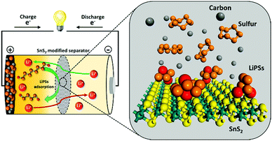
In an effort to understand the correlation between polysulfide adsorption capability and electrochemical performance in Li–S, a series of metal sulfides have been systematically investigated as hosts for Li–S batteries by the Yi Cui group.22 Recently, SnS2/graphene had been proposed as an efficient sulfur host for Li–S batteries. Although such advanced cathode composite designs have shown admirable improvement in enhancing the Li–S performance by providing decent conductivity and sulfur confinement, complex and costly fabrication process of the sulfur cathode composites are not conducive to the commercial applications. In addition, high amount of trapping materials needed to effectively suppress lithium polysulfide shuttle in sulfur composite, which eventually reduces the overall energy density of Li–S battery.21–23 It would be highly desirable to identify novel materials and advanced strategies, which can not only trap polysulfides but also increase the Li-ion conductivity to enhance the rate capability. Herein, we demonstrate an innovative and simple strategy to effectively trap polysulfides using a SnS2-modified separator. A conceptual illustration of the SnS2-modified separator with further elaboration of the role of each component in the electrode is provided (Scheme 1). This sulfide-modified separator enables the achievement of a battery system with high specific capacity, high areal capacity, and remarkable rate capability with significant cycle-life.
Results and discussion
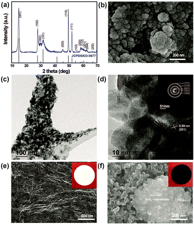
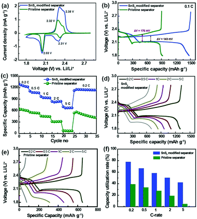
To confirm the phase purity and crystal structure of the synthesized materials, XRD analysis was carried out. Accordingly, Fig. 1a shows the powder XRD patterns for as-prepared SnS2 nanosheets obtained from the hydrothermal reaction between SnCl4·5H2O and thioacetomide. It can be seen that no peaks are observed corresponding to Sn and S, indicating a pure phase of SnS2 (JCPDS Card no. 23-677). All the hkl values were indexed to the hexagonal crystal phase, which is in good agreement with the reported values. Fig. 1b shows the morphology of the as-prepared SnS2 products that are uniformly distributed nanosheets. The TEM images of SnS2 in Fig. 1c clearly reveals the sheet like morphology of SnS2 with an average particle size of ∼30 nm. The HR-TEM image in Fig. 1d clearly depicts the layered structure with a d-spacing spacing of ∼0.59 nm along with ∼10 layers of SnS2. Additionally, the selected area electron diffraction (SAED) pattern in inset: Fig. 1d suggests the polycrystalline nature of SnS2 nanosheets.33Fig. 1e and f show SEM images of the pristine separator and SnS2-modified separator, respectively, used to investigate the effect of the metal sulfide on the pore structures, and its morphological changes upon modification. As seen in Fig. 1e, the pristine separator exhibits a uniformly inter-connected submicron pore structure providing excellent ionic pathways and preventing the transfer of electrons between the cathode and anode. It can be clearly seen that there is a significant change in the morphology of the pristine separator compared to the modified separator. The surface of the modified Celgard separator was uniformly coated with SnS2 and KB particles with a thickness of approximately 4 μm (ESI,† Fig. S1). The SnS2 nanosheeets were mixed with KB particles to enhance the conductivity of the coating layer in the separator (referred as SnS2-modified separator). After modification, a dense layer of sulfide nanosheets and KB covers the surface of the separator and the nanopores of the separator. Corresponding snapshots in the insert in Fig. 1e and f show a color change from white to black after surface coating with the SnS2 nanosheets and KB nanoparticles. Although the modified separator shows an increased thickness and SnS2 particles could decrease the porosity, the improved electrolyte wettability of SnS2-modified separator than pristine separator (Fig. S2, ESI†) can overcome those negative effect. The enhanced wettability in modified separator reduces the interface resistance and enhance the transport of Li+, which is essential to improve the overall electrochemical performance of Li–S batteries overall electrochemical performance of Li–S batteries.34The electrochemical performance of the Li–S cells built using the pristine separator and SnS2-modified separator is shown in Fig. 2. The sulfur cathodes are prepared simply by mixing elemental sulfur, carbon and binder, with an areal sulfur loading for the electrode of ∼3.1 mg cm−2. In Fig. 2a, the CV curves recorded at 0.05 mV s−1 show two cathodic peaks located at approximately 2.31 and 2.03 V, which are assigned to the conversion of sulfur to soluble high-order polysulfides (Li2Sx, x ≥ 4) and the subsequent production of solid short-chain Li2S/Li2S2. The peaks at 2.32 and 2.38 V result from the delithiation of low-order lithium sulfides and high order LiPSs, respectively, to form elemental sulfur.34 Although the shapes of the CV curves remain the same, the difference in peak current density clearly indicates a change in capacity.
With the aim of understanding the effect of the SnS2-modified separator on the electrochemical performance of the Li–S batteries, Li–S cells were subjected to charge–discharge cycling. Fig. 2b shows the charge–discharge voltage profiles measured at a rate of 0.1C for the Li–S cells built using the pristine separator and the SnS2-modified separator. The entire plateau for the charge–discharge processes exactly reflects the peak positions for the CV curves, which clearly indicates sulfur redox reactions between the sulfur and polysulfides. The first plateau at 2.36–2.27 V corresponds to the reduction of elemental sulfur to higher order LiPSs, while the second plateau at approximately 2.09 V is due to the conversion of higher order LiPSs to lower order LiPSs. Furthermore, the two plateaus at approximately 2.32 and 2.38 V are due to the oxidation of low order and high order LiPSs to form elemental sulfur. Interestingly, a difference in the voltage hysteresis is observed for charging and discharging at average capacity for both the pristine and modified separator cells (ΔVSnS2-modified separator = 143 mV; ΔVPristine separator = 176 mV). This difference in voltage hysteresis is mainly attributed to the low polarization of the SnS2-modified separator.22 The initial discharge capacities for the Li–S cells with a pristine and SnS2-modified separator were estimated to be 897 and 1476 mA h g−1 at 0.1C, respectively. The higher initial discharge capacity is indicative of greater active material utilization in the Li–S cell with a SnS2-modified separator. Therefore, it is well validated that the SnS2-modified separator facilitated efficient inhibition of polysulfide migration and the reactivation of trapped polysulfides.
To investigate the advantage of the SnS2-modified separator and its feasibility for practical application, the rate performance of Li–S cells built using the SnS2-modified separator and pristine separator were evaluated at different C rates range from 0.2 to 5C (Fig. 2c). The discharge capacities of the SnS2-modified cell were found to be 1297, 1107, 965, 832 and 700 mA h g−1 at C-rates of 0.2, 0.5, 1.0, 2.0 and 5.0, respectively. The discharge capacity of the SnS2-modified separator cell decreased from 1297 to 1107 mA h g−1 as the current density increased from 0.2C to 0.5C. When the cells were operated at 0.2C after being subjected to a high C-rate (5C), it was possible to recover the original capacity at 0.2C, thus demonstrating excellent rate capability and capacity retention. This performance is noticeably better than the cells with the pristine separator. The corresponding charge–discharge profile at different current rates are shown in Fig. 2d and e. The two discharge plateaus at 2.3 and 2.0 V can be still observed even at a high C-rate corresponding to the two-stage conversion reaction of sulfur to higher/lower order LiPSs in the charge–discharge profile of the cell with SnS2-modified separator, while almost no plateaus can be noticed in that with pristine separator. In addition, the cell with SnS2 modified separator shows significantly smaller voltage hysteresis at high rates compared to cell with pristine separator (Fig. S3, ESI†). The excellent electrochemical performance is mainly due to the incorporation of SnS2 modified separator, which can inhibit the shuttling of LiPSs via both physical and chemical interaction. Furthermore, SnS2 modified separator can provide fast transport path for electron and lithium ion during the charge–discharge processes, thus improving the utilization of active materials (Fig. 2f). The specific capacity obtained at 0.2, 0.5, 1, 2, and 5C corresponds to the initial capacity achieved based on the theoretical capacity of sulfur (1675 mA h g−1). In contrast, the cell with pristine separator shows poor capacity utilization rate, indicating the low utilization of active material. The performance of Li–S batteries using the SnS2-modified separator was also compared to several other batteries incorporating high-performance single modified separators or a bifunctional interlayer (Table 1). The areal capacity of the Li–S cell with the modified separator is 4.54 mA h cm−2 at 0.1C, 4.03 mA h cm−2 at 0.2C and 2.17 mA h cm−2 at 5C.
| Modified separator | Sulfur content (%) | Sulfur loading (mg cm−2) | Loading on the separator (mg cm−2) | Cycle performance (mA h g−1) | Cycles | Rate behavior (mA h g−1) | Ref. |
|---|---|---|---|---|---|---|---|
| SnS 2 -Modified separator | 70 | 3.1 | 0.6 | 1040 at 0.2C | 150 | 700 at 5C | This work |
| 927 at 2C | 500 | ||||||
| Al2O3 coated separator | 60 | 1.6 | 593 at 0.2C | 50 | 453 at 1C | 24 | |
| Acetylene black-CoS2 coated separator | 77.8 | 1.5–2 | 0.5–0.7 | 380 at 2C | 450 | 475 at 4C | 27 |
| MoS2 modified separator | 65 | 401 at 0.5C | 600 | 770 at 1C | 34 | ||
| Three layers of Ketjen black modified separator | 70 | 1.5 | 770 at 2C | 150 | 300 at 6C | 35 | |
| 522 at 4C | |||||||
| MWCNT @PEG-modified separator | 60 | 1.60 | 0.26 | 490 at 0.5C | 500 | 657 at 5C | 29 |
| Inactive interlayer modified separator | 58 | 2.0 | 0.30 | 644 at 0.5C | 150 | 625 at 1C | 36 |
| Porous nitrogen and phosphorous doped graphene | 70 | 1.5 | 1.0–1.1 | 638 at 1C | 500 | 633 at 2C | 37 |
| BaTiO3 coated separator | 60 | 5.0 | 2.4 | 929.5 at 0.1C | 50 | 38 | |
| PVDF-C layer coated separator | 64 | 1.1 | 0.068 | 669 at 0.5C | 500 | 393 at 5C | 39 |
| MOF-based separator | 70 | 0.6–0.8 | 1000 at 1C | 1000 | 537 at 3C | 40 | |
| PANiNF/MWCNT coated separator | 60 | 1.4 | 0.01 | 1020 at 0.2C | 100 | 612 at 1C | 28 |
| PEDOT:PSS coated separator | 64 | 914 at 0.25C | 1000 | 751 at 2C | 41 | ||
| Porous graphene coated separator | 63 | 1.8–2.0 | 0.54 | 1165 at 0.5C | 150 | 479 at 5C | 42 |
To the best of the authors’ knowledge, the SnS2-modified separator exhibits a remarkable rate performance because of its unique polysulfide adsorption capability. For comparison, P. Zheng et al. previously reported an acetylene black (AB)–CoS2 modified separator that showed a reasonably high rate and extended cycle life in Li–S batteries.27 The AB–CoS2 modified separator cell exhibited a specific capacity of 475 mA h g−1 at 4C. Very interestingly; the present SnS2-modified separator delivered 700 mA h g−1 even at a higher C-rate (5C). The rate performance for the SnS2-modified separator was also superior to that reported for a MoS2-modified separator,34 revealing the robust nature of the polysulfide adsorption for suppressing polysulfide migration. A SnS2/S/C composite electrode delivered only 250 mA h g−1 at 5C while the SnS2-modified separator exhibited a much higher capacity even at the same rate, which clearly indicates a remarkable rate performance for the cell with the SnS2-modified separator.43
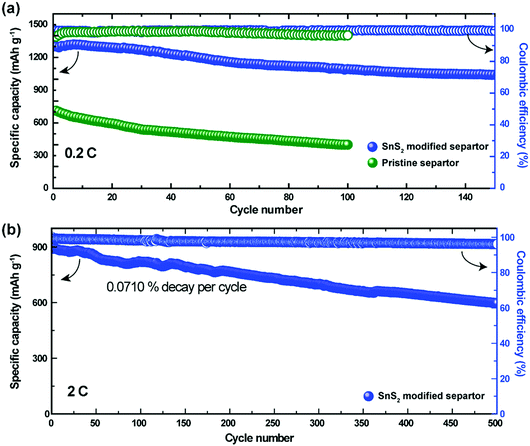
To determine feasibility for practical applications, cycle-life testing is considered as one of the primary data benchmarks. Fig. 3a demonstrates the cycling performance of the Li–S cells with the pristine and the SnS2-modified separators at 0.2C. Both cells delivered initial capacities of 897 mA h g−1 and 1300 mA h g−1 corresponding to 54% and 78% of their theoretical capacity, respectively. After 50 cycles, the specific capacity of the cell with the SnS2-modified separator was found to be approximately 1195 mA h g−1, which is 91.9% of its initial capacity. However, the cells with the pristine separator exhibited a much lower capacity (500 mA h g−1) after 50 cycles compared to the cells with the modified separator. Upon further cycling, the capacities of the pristine and SnS2-modified separator decreased to 400 and 1050 mA h g−1 respectively. The capacity of the SnS2-modified separator stabilized at 1000 mA h g−1 even after 150 cycles, indicating remarkable cycling stability due to polysulfide inhibition during charge–discharge cycling. The coulombic efficiency of the Li–S cells with the pristine separator and modified separator was 96% (after 100 cycles) and 99% (after 150 cycles), respectively. Fig. 3b shows the long-term cycling stability of the Li–S cell with the SnS2-modified separator at a current rate of 2C. The cell with the modified electrode delivers a reversible capacity of 597 mA h g−1 at the 500th cycle, with a high coulombic efficiency of 96%. The enhanced electrochemical performance of the Li–S cell with a SnS2-modified separator suggests that the migration of LiPSs was greatly suppressed via physical and chemical interaction between the SnS2-modified separator and the dissolved LiPSs.
To understand the significant impact of the modified separator in our Li–S cells, the conductivity of the SnS2-modified separator was measured by the four-probe test method. The electrical conductivity of the SnS2-modified separator is 2.291 S cm−1, demonstrating fast electron transfer at the interface. Additionally, ionic conductivity of the pristine and modified separators were determined from Nyquist plots of the SS/separator/SS cell.34 The ionic conductivity of the pristine separator and SnS2-modified separators were calculated to be 0.76 mS cm−1 and 0.84 mS cm−1, respectively (Fig. S4, ESI†). Although the SnS2-coating layer changed the surface porosity of the pristine separator, the SnS2-modified separator displayed higher ionic conductivity. This could be due to the enhanced electrolyte wettability of the SnS2-modified separator. To further understand the significant impact of the modified separator in our Li–S cells, electrochemical impedance spectroscopic analysis (EIS) was carried out before and after cycling. Typical EIS data with equivalent circuit models were shown in Fig. 4 and the electrochemical impedance parameters are summarized in Table S1 (ESI†). The Nyquist plot shown in the intercept on the real axis at high frequency corresponds to the ohmic resistance (Rs) of the electrode and electrolyte. The Ohmic resistance for both pristine and SnS2-modified separators were almost similar, indicating the same electrode and electrolyte environment. A single semicircle in the high-to-medium frequency region is related to charge-transfer resistance (Rct), while the inclined line at low frequency region is associated with Warburg impedance (Ws), and constant phase elements (CPE) corresponds to double layer capacitance. As shown, Rct values of the cell with SnS2-modified separator (23.74 Ω) is lower than that for the pristine separator (45.45 Ω), indicating an enhanced the active material utilization to deliver a high capacity. Furthermore, the variation in charge transfer resistance clearly confirms that SnS2-modified separator has more conductive and stable structure than pristine separator, resulting in superior electrochemical performance in the Li–S cell. Impedance data were also collected after cycling (Fig. 4b) to identify any changes in charge transfer resistance. As expected, the charge transfer resistance of the cell with SnS2-modified separator showed a lower Rct value (9.341 Ω) than the cell with pristine separator (28.6 Ω), which is mainly due to the high electrical conductivity and improved electrolyte wettability between the separator and sulfur cathode. The above results confirmed the benefits of SnS2-modified separator in improving electrochemical performance Li–S cell.35
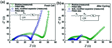 | ||
| Fig. 4 Electrochemical impedance spectra of Li–S batteries with a pristine separator and a SnS2-modified separator (a) fresh cell (b) after 150 cycles at a rate of 0.2C. | ||
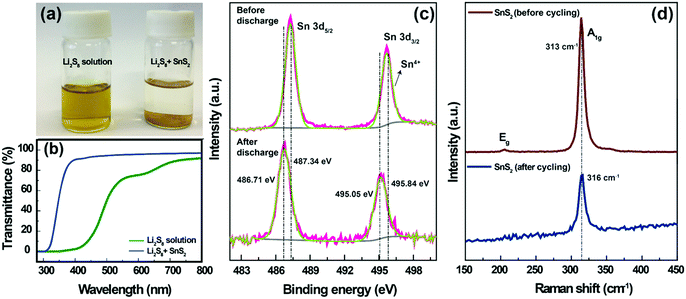
To understand the lithium polysulfide interaction with SnS2, an adsorption ability test was carried out. For the adsorption test, a 1 mM Li2S8 solution was prepared by chemically reacting elemental sulfur with Li2S in a DOL/DME (1![[thin space (1/6-em)]](https://www.rsc.org/images/entities/char_2009.gif) :
:![[thin space (1/6-em)]](https://www.rsc.org/images/entities/char_2009.gif) 1 by volume) solution. The Li2S8 solution was initially yellow in color. The addition of SnS2 to the Li2S8 solution resulted in a concomitant color change from yellow to colorless (Fig. 5a). This strongly suggests that SnS2 was strongly bound with the polysulfides.23 The polysulfide interaction with SnS2 is clearly reflected in the cycling ability (Fig. 3a and b). The UV-Vis spectra (Fig. 5b) for a bare Li2S8 solution showed a peak at approximately 620 nm (75% transmittance), which is characteristic of S3˙−, resulting from the dissociation of S62− (S62− → 2S3˙−). Moreover, the transmittance values decreased to 0% in the wavelength range of 400–500 nm, which indicates the existence of higher order polysulfides (S82−, S62−, S42−), respectively.35 With the addition of SnS2, the characteristic peaks in the wavelength range of 400–500 (∼90% transmittance) and 620 nm (∼98% transmittance) completely disappeared, which demonstrates the strong adsorption of polysulfides within our designed system.
1 by volume) solution. The Li2S8 solution was initially yellow in color. The addition of SnS2 to the Li2S8 solution resulted in a concomitant color change from yellow to colorless (Fig. 5a). This strongly suggests that SnS2 was strongly bound with the polysulfides.23 The polysulfide interaction with SnS2 is clearly reflected in the cycling ability (Fig. 3a and b). The UV-Vis spectra (Fig. 5b) for a bare Li2S8 solution showed a peak at approximately 620 nm (75% transmittance), which is characteristic of S3˙−, resulting from the dissociation of S62− (S62− → 2S3˙−). Moreover, the transmittance values decreased to 0% in the wavelength range of 400–500 nm, which indicates the existence of higher order polysulfides (S82−, S62−, S42−), respectively.35 With the addition of SnS2, the characteristic peaks in the wavelength range of 400–500 (∼90% transmittance) and 620 nm (∼98% transmittance) completely disappeared, which demonstrates the strong adsorption of polysulfides within our designed system.
Furthermore, the interaction between LiPSs and SnS2 was also investigated by XPS and Raman analysis. The SnS2-modified separator (before and after discharge state) was used for the XPS analysis. The Sn 3d spectra of the SnS2-modified separator (before discharging) are shown in Fig. 5c; the two peaks located at 487.34 and 495.84 eV, with an energy separation of 8.5 eV, are attributed to the Sn 3d5/2 and Sn 3d3/2 spin orbit levels of SnS2.44 After discharging, both Sn 3d peaks shift by approximately 0.63 to 0.79 eV towards a lower binding energy, confirming the strong adsorption capability for Sn–Sn2− with LiPSs. Fig. 5d shows the Raman spectra measured for the SnS2-modified separator (before and after cycling). The SnS2-modified separator (before cycling) shows a strong peak at ∼313 cm−1, which corresponds to the first-order, in-plane vibrational A1g mode of SnS2. The characteristic A1g peak of SnS2 at 313 cm−1 shows a positive shift (after cycling), indicating polysulfide trapping in SnS2 by providing electrons to surrounding LiPSs.45 These results further verify the strong binding between the SnS2 and polysulfide.
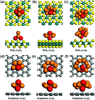
To further investigate the binding nature of the polysulfide on SnS2, DFT calculations were carried out. In this study, graphene was chosen for comparison due to commonality in use as a conductive coating material in Li–S batteries. We investigated the adsorption of Li2Sn species (n = 4, 6 and 8) on graphene and SnS2. Since the chemical interaction mainly arises due to lithium ions,46 we considered both 1- and 2-fold adsorption geometries for each case. The most stable adsorption configurations on graphene and SnS2 substrates are shown in Fig. 6. Except for Li2S4 adsorption on SnS2, 1-fold adsorption is preferred for all other cases. Table 2 lists the adsorption energies. The Li2Sn adsorption energy on graphene is only approximately 0.1 eV, but that on SnS2 is in the range of −0.2–−0.5 eV. Clearly, the adsorption of polysulfide on SnS2 is significantly enhanced, especially for the Li2S4, which is stabilized by −0.5 eV compared to adsorption on graphene. This difference in the binding nature between SnS2 and graphene can be easily explained by calculating the charge transfer between the two materials. Bader analysis47,48 shows that 0.98e, 0.31e, 0.20e of charge is transferred from Li2S4, Li2S6, and Li2S8 to the SnS2 substrate, respectively, but negligible charge transfer occurs during adsorption on graphene. Therefore, a strong chemical interaction exists between polysulfide and SnS2, but only physical interaction, such as via the van der Waals force, dominates in the Li2Sn–graphene system.
| Model cluster | SnS2 [eV] | Graphene [eV] | Δ [eV] |
|---|---|---|---|
| Li2S4 | −0.50 | −0.14 | −0.36 |
| Li2S6 | −0.19 | −0.10 | −0.09 |
| Li2S8 | −0.23 | −0.11 | −0.12 |
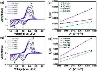
To estimate the Li-ion diffusion coefficient (DLi+) for the pristine and SnS2-modified separators, a series of cyclic voltammograms at different scan rates were recorded. As indicated in Fig. 7, cathodic peaks are identified at approximately 2.3 V and 2.03 V, which are labeled A and B, respectively, corresponding to the reduction in elemental sulfur to long-order polysulfides (Li2Sx, x ≥ 4) and the subsequent formation of short-order polysulfides (Li2S2/Li2S). The anodic peaks at approximately 2.4 V, labeled C, result from the transition of Li2S2/Li2S to polysulfides and elemental sulfur. The Randles–Sevick equation was used to obtain values for DLi+, as given below.32
| Ip = 2.69 × 10⁵n1.5ADLi+0.5CLiν0.5 |
As shown in Fig. 7a–d, the linear relationship between the peak current (Ip) and square root of the scan rate (ν0.5) indicates a diffusion controlled process. The diffusion coefficients (DLi+) for the Li–S batteries with the pristine separator and SnS2-modified separator are compiled in Table S2 (ESI†). The diffusion coefficients were calculated to be DLi+ (A) = 3.176 × 10⁻⁸ cm2 s−1, DLi+ (B) = 1.792 × 10⁻⁸ cm2 s−1, and DLi+ = 1.499 × 10⁻⁷ cm2 s−1 for the Li–S cell with the pristine separator. For the SnS2-modified separator, the calculated diffusion coefficient values were estimated to be DLi+ (A) = 3.272 × 10⁻⁷ cm2 s−1, DLi+ = 2.22 × 10⁻⁷ cm2 s−1, and DLi+ = 9.811 × 10⁻⁷ cm2 s−1. It is clearly observed that the Li–S cell with the SnS2-modified separator exhibits higher lithium ion diffusion coefficient values compared to the Li–S cell with the pristine separator, indicating that the incorporation of the SnS2 host enables a highly efficient catalyzing conversion of the polysulfide redox.34
To better understand the morphological changes in the separator before and after cycling, a postmortem analysis was carried out for the pristine, modified separator and Li anode after 150 cycles at 0.2C. Fig. 8a shows an SEM image for the pristine separator after cycling, which reveals that the pores in the pristine separator were completely blocked by the agglomeration of sulfur-related species. This blocking can retard the lithium ion transport, thus, resulting in poor electrochemical performance.49–51 Compared to the morphology of the fresh SnS2-modified separator in Fig. 1f, the morphology of the SnS2-modified separator after cycling (Fig. 8b and Fig. S5, ESI†) shows deposition of sulfur species on the SnS2 nanosheets, indicating that the SnS2-modified separator acts as a matrix to trap and suppress polysulfide migration. An uneven passivation layer with cracks was observed on the Li anode surface of the Li–S cell with the pristine separator due to the side reaction between the migrated sulfur species and metallic Li (Fig. 8c). In contrast, the Li–S cell with the SnS2 treated separator showed a much smoother Li metal anode surface, as shown in Fig. 8d, due to suppression of the LiPSs shuttle effect and effective conversion of the sulfur redox realized by the SnS2. Further, The cells with pristine and separator were dissembled after cycling to find evident for LiPSs trapping (Fig. S6, ESI†). LiPSs deposition over lithium metal anode is observed for the cell with pristine separator, whereas no such deposition is noted with SnS2-modified separator.
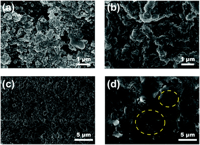 | ||
| Fig. 8 SEM images of the separators after 150 cycles at 0.2C (a) pristine, (b) SnS2-modified separator, and (c and d) corresponding SEM images on lithium metal anode surface. | ||
Conclusion
In summary, we have successfully introduced a SnS2-modified Celgard separator for Li–S batteries. This modified separator provides a highly efficient method for suppressing shuttling of LiPSs, leading to high Coulombic efficiency and long cycling stability. The Li–S cell with a SnS2-modified separator achieved an excellent rate performance of 700 mA h g−1 at 5C, with high areal capacities. The specially coated SnS2 modified separator not only captured polysulfides efficiently by a strong chemical and physical interaction but also ensured the rapid diffusion of lithium ions. Moreover, the SnS2 coating can potentially serve as an excellent current collector for facilitating electron and ion transport; thus, enhancing the utilization of sulfur and ensuring reactivation of the trapped active material. The approach demonstrated in this work provides an additional insight into the development of similar strategies for high-energy-density and stable Li–S batteries.Conflicts of interest
There are no conflicts to declare.Acknowledgements
This project was supported by the National Research Foundation of Korea (NRF) (MSIP) (No. 2017R1A2B2010148) and the Climate Change Research Hub of EEWS from KAIST (Grant No. N11180108). P. R. is grateful to the Korean Federation of Science and Technology Societies for financial support through the Brain Pool Program and Dr V. K. Pillai, Director, CSIR-CECRI, for his support and granting him the sabbatical leave.Notes and references
- J. M. Tarascon and M. Armand, Nature, 2001, 414, 359–367 CrossRef CAS PubMed.
- M. Armand and J. M. Tarascon, Nature, 2008, 451, 652–657 CrossRef CAS PubMed.
- L. Luo, S.-H. Chung and A. Manthiram, J. Mater. Chem. A, 2018, 6, 7659–7667 RSC.
- R. Tripathi, S. M. Wood, M. S. Islam and L. F. Nazar, Energy Environ. Sci., 2013, 6, 2257–2264 RSC.
- R. Thangavel, B. Moorthy, D. K. Kim and Y.-S. Lee, Adv. Energy Mater., 2017, 7, 1602654 CrossRef.
- S. Evers and L. F. Nazar, Acc. Chem. Res., 2013, 46, 1135–1143 CrossRef CAS PubMed.
- X. Liu, J.-Q. Huang, Q. Zhang and L. Mai, Adv. Mater., 2017, 29, 1601759 CrossRef PubMed.
- X. Song, S. Wang, G. Chen, T. Gao, Y. Bao, L.-X. Ding and H. Wang, Chem. Eng. J., 2018, 333, 564–571 CrossRef CAS.
- R. Ponraj, A. G. Kannan, J. H. Ahn, J. H. Lee, J. Kang, B. Han and D.-W. Kim, ACS Appl. Mater. Interfaces, 2017, 9, 38445–38454 CrossRef CAS PubMed.
- X. B. Cheng, R. Zhang, C. Z. Zhao, F. Wei, J. G. Zhang and Q. Zhang, Adv. Sci., 2015, 3, 1–20 Search PubMed.
- Q. Pang, X. Liang, C. Y. Kwok and L. F. Nazar, J. Electrochem. Soc., 2015, 162, A2567–A2576 CrossRef CAS.
- Z. Yuan, H. J. Peng, T. Z. Hou, J. Q. Huang and C. M. Chen, Nano Lett., 2016, 16, 519–527 CrossRef CAS PubMed.
- S. A. Ahad, P. Ragupathy, S. Ryu, H. W. Lee and D. K. Kim, Chem. Commun., 2017, 53, 8782–8785 RSC.
- S. Moon, Y. H. Jung and D. K. Kim, J. Power Sources, 2015, 294, 386–392 CrossRef CAS.
- S. Moon, J.-K. Yoo, Y. H. Jung, J.-H. Kim, Y. S. Jung and D. K. Kim, J. Electrochem. Soc., 2017, 164, A6417–A6421 CrossRef CAS.
- J. Guo, X. Du, X. Zhang, F. Zhang and J. Liu, Adv. Mater., 2017, 29, 1700273 CrossRef PubMed.
- S. Moon, Y. H. Jung, W. K. Jung, D. S. Jung, J. W. Choi and D. K. Kim, Adv. Mater., 2013, 25, 6547–6553 CrossRef CAS PubMed.
- J. H. Yun, J. H. Kim, D. K. Kim and H. W. Lee, Nano Lett., 2018, 18, 475–481 CrossRef CAS PubMed.
- R. Ponraj, A. G. Kannan, J. H. Ahn and D.-W. Kim, ACS Appl. Mater. Interfaces, 2016, 8, 4000–4006 CrossRef CAS PubMed.
- K. Xie, Y. You, K. Yuan, W. Lu, K. Zhang, F. Xu, M. Ye, S. Ke, C. Shen, X. Zeng, X. Fan and B. Wei, Adv. Mater., 2016, 29, 1604724 CrossRef PubMed.
- Y. C. Jeong, J. H. Kim, S. H. Kwon, J. Y. Oh, J. Park, Y. Jung, S. G. Lee, S. J. Yang and C. R. Park, J. Mater. Chem. A, 2017, 5, 23909–23918 RSC.
- Q. Zhang, Y. Wang, Z. W. Seh, Z. Fu, R. Zhang and Y. Cui, Nano Lett., 2015, 15, 3780–3786 CrossRef CAS PubMed.
- G. Zhou, H. Tian, Y. Jin, X. Tao, B. Liu, R. Zhang, Z. W. Seh, D. Zhuo, Y. Liu, J. Sun, J. Zhao, C. Zu, D. S. Wu, Q. Zhang and Y. Cui, Proc. Natl. Acad. Sci. U. S. A., 2017, 114, 840–845 CrossRef CAS PubMed.
- Z. Zhang, Y. Lai, Z. Zhang, K. Zhang and J. Li, Electrochim. Acta, 2014, 129, 55–61 CrossRef CAS.
- S. Yao, J. Cui, J.-Q. Huang, Z. Lu, Y. Deng, W. G. Chong, J. Wu, M. I. U. Haq, F. Ciucci and J.-K. Kim, Adv. Energy Mater., 2018, 8, 1800710 CrossRef.
- W. K. Shin, A. G. Kannan and D. W. Kim, ACS Appl. Mater. Interfaces, 2015, 7, 23700–23707 CrossRef CAS PubMed.
- P. Zeng, L. Huang, X. Zhang, Y. Han and Y. Chen, Appl. Surf. Sci., 2017, 427, 242–252 CrossRef.
- C.-H. Chang, S.-H. Chung and A. Manthiram, J. Mater. Chem. A, 2015, 3, 18829–18834 RSC.
- G. Wang, Y. Lai, Z. Zhang, J. Li and Z. Zhang, J. Mater. Chem. A, 2015, 3, 7139–7144 RSC.
- L. Shi, F. Zeng, X. Cheng, K. H. Lam, W. Wang, A. Wang, Z. Jin, F. Wu and Y. Yang, Chem. – Eng. J., 2017, 335, 305–312 Search PubMed.
- S. H. Chung and A. Manthiram, Adv. Mater., 2014, 26, 1360–1365 CrossRef CAS PubMed.
- J. Q. Huang, T. Z. Zhuang, Q. Zhang, H. J. Peng, C. M. Chen and F. Wei, ACS Nano, 2015, 9, 3002–3011 CrossRef CAS PubMed.
- R. Thangavel, A. Samuthira Pandian, H. V. Ramasamy and Y.-S. Lee, ACS Appl. Mater. Interfaces, 2017, 9, 40187–40196 CrossRef CAS PubMed.
- Z. A. Ghazi, X. He, A. M. Khattak, N. A. Khan, B. Liang, A. Iqbal, J. Wang, H. Sin, L. Li and Z. Tang, Adv. Mater., 2017, 29, 1–6 CrossRef PubMed.
- H. Tang, S. Yao, X. Shen, X. Xi and K. Xiao, Energy Technol., 2017, 5, 623–628 CrossRef CAS.
- N. Liu, B. Huang, W. Wang, H. Shao, C. Li, H. Zhang, A. Wang, K. Yuan and Y. Huang, ACS Appl. Mater. Interfaces, 2016, 8, 16101–16107 CrossRef CAS PubMed.
- X. Gu, C.-j. Tong, C. Lai, J. Qiu, X. Huang, W. Yang, B. Wen, L.-m. Liu, Y. Hou and S. Zhang, J. Mater. Chem. A, 2015, 3, 16670–16678 RSC.
- T. Yim, S. H. Han, N. H. Park, M. S. Park, J. H. Lee, J. Shin, J. W. Choi, Y. Jung, Y. N. Jo, J. S. Yu and K. J. Kim, Adv. Funct. Mater., 2016, 26, 7817–7823 CrossRef CAS.
- H. Wei, J. Ma, B. Li, Y. Zuo and D. Xia, ACS Appl. Mater. Interfaces, 2014, 6, 20276–20281 CrossRef CAS PubMed.
- S. Bai, X. Liu, K. Zhu, S. Wu and H. Zhou, Nat. Energy, 2016, 1, 16094 CrossRef CAS.
- Y. Yang, G. Yu, J. J. Cha, H. Wu, M. Vosgueritchian, Y. Yao, Z. Bao and Y. Cui, ACS Nano, 2011, 5, 9187–9193 CrossRef CAS PubMed.
- P. Y. Zhai, H. J. Peng, X. B. Cheng, L. Zhu, J. Q. Huang, W. Zhu and Q. Zhang, Energy Storage Materials, 2017, 7, 56–63 CrossRef.
- X. Li, Y. Lu, Z. Hou, W. Zhang, Y. Zhu, Y. Qian, J. Liang and Y. Qian, ACS Appl. Mater. Interfaces, 2016, 8, 19550–19557 CrossRef CAS PubMed.
- X. Li, L. Chu, Y. Wang and L. Pan, Mater. Sci. Eng., B, 2016, 205, 46–54 CrossRef CAS.
- Z. Ma, Z. Li, K. Hu, D. Liu, J. Huo and S. Wang, J. Power Sources, 2016, 325, 71–78 CrossRef CAS.
- S. Grimme, J. Antony, S. Ehrlich and H. Krieg, J. Chem. Phys., 2010, 132, 154104 CrossRef PubMed.
- G. Henkelman, A. Arnaldsson and H. Jónsson, Comput. Mater. Sci., 2006, 36, 354–360 CrossRef.
- W. Tang, E. Sanville and G. Henkelman, J. Phys.: Condens. Matter, 2009, 21, 084204 CrossRef CAS PubMed.
- P. Zhu, J. Zhu, J. Zang, C. Chen, Y. Lu, M. Jiang, C. Yan, M. Dirican, R. Kalai Selvan and X. Zhang, J. Mater. Chem. A, 2017, 5, 15096–15104 RSC.
- P. Ragupathy, S. A. Ahad, P. R. Kumar, H.-W. Lee and D. K. Kim, Adv. Sustainable Syst., 2017, 1, 1700083 CrossRef.
- S. A. Ahad, P. R. Kumar, J. H. Kim, P. Ragupathy and D. K. Kim, Electrochim. Acta, 2017, 246, 451–458 CrossRef.
Footnote |
| † Electronic supplementary information (ESI) available. See DOI: 10.1039/c8nh00172c |
| This journal is © The Royal Society of Chemistry 2019 |

