DOI:
10.1039/C8SC04475A
(Perspective)
Chem. Sci., 2019,
10, 16-33
Proton transfer in hydrogen-bonded degenerate systems of water and ammonia in metal–organic frameworks
Received
8th October 2018
, Accepted 26th November 2018
First published on 28th November 2018
Abstract
Porous crystalline metal–organic frameworks (MOFs) or porous coordination polymers (PCPs) are emerging as a new class of proton conductors with numerous investigations. Some of the MOFs exhibit an excellent proton-conducting performance (higher than 10−2 S cm−1) originating from the interesting hydrogen(H)-bonding networks with guest molecules, where the conducting medium plays a crucial role. In the overwhelming majority of MOFs, the conducting medium is H2O because of its degenerate conjugate acid–base system (H3O+ + H2O ⇔ H2O + H3O+ or OH− + H2O ⇔ H2O + OH−) and the efficient H-bonding ability through two proton donor and two acceptor sites with a tetrahedral geometry. Considering the systematic molecular similarity to water, ammonia (NH3; NH4+ + NH3 ⇔ NH3 + NH4+) is promising as the next proton-conducting medium. In addition, there are few reports on NH3-mediated proton conductivity in MOFs. In this perspective, we provide overviews of the degenerate water (hydronium or hydroxide)- or ammonia (ammonium)-mediated proton conduction system, the design strategies for proton-conductive MOFs, and the conduction mechanisms.
 Dae-Woon Lim | Dae-Woon Lim is an Assistant Professor in the Division of Chemistry, Graduate School of Science, Kyoto University. He received his PhD in 2014 from Seoul National University (SNU) in Korea under the supervision of Professor Myunghyun Paik Suh. After that he moved to the Korea Atomic Energy Research Institute (KAERI, 2014–2016) and Kyoto University (2016) as a postdoctoral researcher. He became an Assistant Professor at Kyoto University in 2018. His research interests cover the design of porous metal–organic frameworks and nano-composite materials for gas storage, catalysis and ionic conductivity. |
 Masaaki Sadakiyo | Masaaki Sadakiyo is an Assistant Professor at the International Institute for Carbon-Neutral Energy Research (WPI-I2CNER), Kyushu University. He received his PhD from Kyoto University in 2012 under the supervision of Professor Hiroshi Kitagawa. He became an Assistant Professor at Kyushu University in 2012. His research interests include proton-conductive metal–organic frameworks, hydroxide ion-conductive metal–organic frameworks, other ion-conduction in nano-structured materials, novel hybrid catalysts of metal nanoparticles and metal–organic frameworks, and flow reactors such as fuel cells and electrolyzers. |
 Hiroshi Kitagawa | Hiroshi Kitagawa, born in December 1961 in Osaka, finished his PhD at Kyoto University in 1991 and, after working as an Assistant Professor at IMS (Okazaki) and JAIST (Kanazawa), he was appointed as an Associate Professor at the University of Tsukuba in 2000. He became a Professor of Chemistry at Kyushu University in 2003 and moved to Kyoto University as a Professor in 2009. He is now the Vice Provost and Deputy Executive-Vice President for Research at Kyoto University. He is also engaged at the Japan Science & Technology Agency (JST) as a Research Director of ACCEL and is a Director of the network-type research institution “Science and Creation of Innovative Catalysts, PRESTO”. He has published more than 350 original papers on research dealing with solid-state chemistry, coordination chemistry, nano-science, low-dimensional electron systems, and molecule-based conductors. |
1. Introduction
Proton transport based on an acid–base nature is essential and critical in biological systems and electrochemical devices.1–4 According to Brønsted–Lowry theory, an acid and base react with each other by proton transfer forming their conjugate acid–base pair. In particular, the conjugate acid–base pair in one species can provide a degenerate proton conduction chain (i.e. H3O+ + H2O ⇔ H2O + H3O+) where H3O+ and H2O coexist through the mobile proton and the proton suffering from electron depletion is able to be shared by neighbouring electron rich atoms such as oxygen and nitrogen with symmetric hydrogen bonding.1 Solid-state proton conductors (SSPCs) have attracted much attention because of their application as a fuel cell (FC) component for alternative energy. FC technology converts chemical energy into electrical energy without the emission of CO2. In general, solid-state proton conductors show a higher conductivity at room temperature than other solid-state ionic conductors such as Li+ or Na+ conductors because hydrogen bonds have a covalent character and reduce the net charge of the proton, resulting in a reduction in the Coulomb potential of the proton pathway. By contrast, Li+ or Na+ in solids do not have a covalent character and their Coulomb potential is strong, resulting in a large energy barrier height for jump diffusion. For practical use, solid-state electrolytes are required for conductivities higher than 10−2 S cm−1. To date, organic polymers or inorganic materials have been widely used and studied as proton conductors.5–9 For example, CsHSO4 working in a high-temperature range (119 < T < 145 °C) exhibits a high conductivity of 3.7 × 10⁻³ S cm−1 through phase transition. In particular, the organic polymer Nafion, which consists of a perfluorinated polyethylene backbone and a terminal sulfonic acid group, shows high performance (10−1 to 10−2 S cm−1) in the fully hydrated state at a relatively low temperature (T < 85 °C). However, it indicates efficiency degradation during the hydration and dehydration process, implying that the proton conductivity is critically affected by the incorporated proton-conducting medium.
In general, the majority of solid-state proton conductors contain water as the conducting medium10 because there are several aspects to an efficient proton-conducting medium (Scheme 1). Specifically, (1) it obtains the degenerate conjugate acid–base system (H3O+ + H2O ⇔ H2O + H3O+), and (2) it has two proton donor and two acceptor sites on the oxygen atom. Furthermore, these sites can form an H-bonding network with a tetrahedral geometry, which is advantageous for efficient proton hopping by local molecular rotational motion. In addition, (3) it has a small molecular size (kinetic diameter 2.65 Å), which is beneficial for dynamic molecular motion in diffusion and mobility. Moreover, the neutral liquid phase facilitates handling. Therefore, there are a large number of experimental and theoretical studies on proton conduction and diffusion mechanisms in water. For water, two types of proton diffusion mechanisms, the Grotthuss and vehicle mechanisms, are well established.11,12 In the Grotthuss mechanism, a proton moves through the H-bonding networks between the hydronium ion and water, in which proton transfer and sequential molecular rotation occur simultaneously. On the other hand, in the vehicle mechanism, the protic species (H3O+ or NH4+) diffuses by itself as a proton-attached vehicle. These mechanisms can be identified from the activation energy because the required hydrogen bonding cleavage energy penalty is in the range of 2–3 kcal mol−1 (0.09–0.13 eV).11 Therefore, the Grotthuss (Ea < 0.4 eV) and vehicle mechanisms (Ea > 0.4 eV) generally have a difference in the activation energy.13
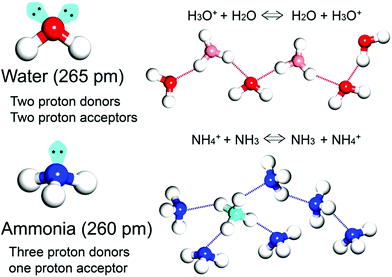 |
| | Scheme 1 Schematic representation of proton transfer in water- and ammonia-conducting media with degenerate systems. | |
As an irreplaceable feedstock, ammonia has received considerable attention because of its various applications, such as in fertilizers14 and pharmaceuticals,15 and as a refrigerant16 and fuel.17 As a result, 150 million tons of ammonia are produced annually on the global scale18 for use as a raw material in the manufacturing industry. In addition, liquid ammonia is used as a unique solvent because it closely approaches water in the ability to dissolve salt-like substances; it impressively dissolves alkali metals and alkali earth metals forming a conductive solution without appreciable reaction taking place.19 In particular, ammonia is promising as a next proton-conducting medium because it has a molecular system most similar to that of water, specifically three proton donor sites and one acceptor site with a tetrahedral geometry, a degenerate conjugate acid–base system (NH4+ + NH3 ⇔ NH3 + NH4+) and a small molecular size (kinetic diameter 2.60 Å). Nevertheless, liquid NH3 shows a low proton conductivity (10−11 Ω−1) without an acid source because of its low auto-ionization constant (2.2 × 10⁻²⁸ at 25 °C).20–23 However, liquid NH3 involving NH4+ reveals a molar conductivity of 142 S cm2 mol−1, which is slightly lower than that of H3O+ in water (350 S cm2 mol−1).21 The handling of NH3 is also advantageous because it is easy to liquify (at ambient temperature and ca. 8 atm or at 240 K and ambient pressure), and the infrastructures for NH3 technology, such as the production, storage, and transport systems, are well established. However, the corrosive gas phase of NH3 is a drawback as a conducting medium. Thus, the proton conductivity of NH3 was typically investigated below the boiling point (<240 K). Therefore, for the practical use of NH3 as a conducting medium, efficient and robust adsorbents are required as a template for encapsulation of NH3 species. Metal–organic frameworks (MOFs) or porous coordination polymers24–27 constructed from metal ions and organic ligands have been of interest in a new class of solid-state proton conductors because of their high crystallinity, chemical tunability, considerable porosity, and versatile adsorption ability. Kanda et al. reported, for the first time, a proton-conductive Cu(II)-type MOF in 1979.28 Since then, noticeable progress has been achieved in this field.13,29–31 In most cases, proton conductive MOFs have been designed with intrinsic or extrinsic proton sources (Fig. 1). The intrinsic proton sources can be classified by their position. One such source is located in pores as counterions, such as H3O+, NH4+, NH2(Me)2+, H2PO4− and OH− that are incorporated in the pore during the MOF synthesis to maintain the neutrality of the framework.32–35 Another source is positioned in the organic strut of frameworks as dangling acid functional groups (–(SO3H), –(COOH), and –(PO3H2)), which are not coordinated to the metal center.36–39 This can provide additional protons to the pore environment. The intrinsic sources form H-bonding networks with the framework and additional water molecules, resulting in improved proton conductivity. The extrinsic sources mean the artificial encapsulation of protic organic molecules (imidazole and histamine) or charge-neutral nonvolatile acids (H2SO4 and H3PO4) in the pores of MOFs through a simple inclusion method.40–43 The pores are filled up by protic guest molecules with the formation of the H-bonding network. As a result, the low pKa value of guest molecules can provide a potent high-proton donation ability at moderate temperatures.
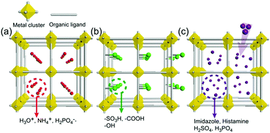 |
| | Fig. 1 Classification of proton sources in metal–organic frameworks: (a and b) intrinsic proton sources and (c) extrinsic proton sources. | |
In general, the ionic conductivity (σ) of MOFs is estimated by the alternating current (AC) impedance measurement of a pelletized microcrystal powder or single crystal in a wide frequency range. The ionic conductivity can be expressed by eqn (1), where z, e, n, and μ mean the valence of the ion, elementary charge, charge carrier concentration, and carrier mobility, respectively. In addition, the proton conduction mechanisms are evaluated through the relationship of conductivity and temperature in eqn (2), where A, kB, and Ea are the pre-exponential factor, Boltzmann constant, and activation energy, respectively.
| | σT = A![[thin space (1/6-em)]](https://www.rsc.org/images/entities/char_2009.gif) exp(−Ea/kBT) exp(−Ea/kBT) | (2) |
Considering eqn (1), proton conductivity can be enhanced by the control of charge carrier concentration and mobility with an improved conduction pathway. Herein, we examine the selective examples of water (hydronium or hydroxide)- and ammonia (ammonium)-mediated degenerate H-bond systems in MOFs. In particular, their design, conduction properties, and diffusion mechanisms are discussed.
2. Water-based degenerate system for proton conduction in MOFs
2.1. Additional protons with water molecules
A water-based degenerate system consisting of H3O+ and H2O (H3O+–H2O system), where these species are connected through H bonds, is important for showing high proton conductivity. Efficient proton transport using the H3O+–H2O system can be described by a combination of a proton jump from H3O+ to a neighboring H2O and molecular rotations, and is named the Grotthuss mechanism.11 Kreuer et al. reported a more detailed conduction mechanism using molecular dynamics (MD) simulations,44 showing that the additional proton in the H3O+–H2O system migrates through a recombination of two species of H5O2+ (Zundel ion) and H9O4+ (Eigen ion) through a proton jump within an H bond. The efficient transportation in H3O+–H2O is also thought to be the origin of the abnormally high mobility of the proton (H+: 36.2 (×10−8 m2 s−1 V−1)) in water solvent compared with other ions (Li+: 4.0 and Na+: 5.2 (×10−8 m2 s−1 V−1)).45 Solid materials showing high proton conductivity at ambient temperature usually have the H3O+–H2O system, as in the case of Nafion.46 However, the structure of the inner H-bonding system in such amorphous organic materials could not be visualized. By contrast, MOFs were recently studied as a platform for visualization of the H-bonding system in a solid state because of its highly crystalline properties. We present an overview of the structure and proton conductivity of water and additional protons, i.e., the H3O+–H2O system, included in MOFs. An oxalate-bridged two-dimensional (2-D) MOF, (NH4)2(H2adp) [Zn2(ox)3]·3H2O (H2adp = adipic acid), showing the coexistence of a carboxylic acid group and a water molecule in the interlayer space, was reported in 2009.47 As shown in Fig. 2, the carboxylic acidic groups, water molecules, and ammonium ions formed 2-D H-bonding networks, where the dicarboxylic acid group of H2adp is expected to give additional protons through partial dissociation. There are several short H bonds between H2adp and ox ions (2.688(4) Å), O(10), and O(9) atoms of water molecules (2.638(12) Å), and N(1) atoms of ammonium ions and O(10) atoms of water molecules (2.789(7) Å), implying that the additional protons should momentarily form the H3O+–H2O system in the pores and could migrate through the Grotthuss mechanism. This compound shows a high proton conductivity of 0.8 × 10⁻² S cm−1 (25 °C, 98% relative humidity (RH)), which is comparable to that of Nafion. From the results of the temperature dependence of proton conductivity, the activation energy was estimated to be 0.63 eV, whereas the conduction mechanism in this compound was expected to be the Grotthuss mechanism because of its closely packed guest molecules. The reason for the relatively high activation energy might be attributed to some direct diffusion process in the proton transfer in this compound, which is implied by the 50% occupancy of O(10) atoms with a remarkably short distance between O(10) and O(10)′ (2.189 Å). The crystalline character of MOFs gave us the opportunity to discuss such a relationship between the structure of the H-bonding network and additional acid groups in the solid.
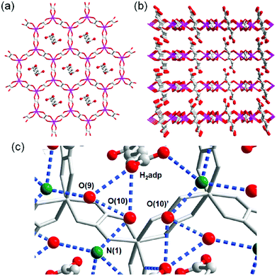 |
| | Fig. 2 (a) Honeycomb layer structure of (NH4)2(H2adp)[Zn2(ox)3]·3H2O. (b) Perspective view along the b-axis. Guest molecules are omitted. (c) H-bond arrangements of –COOH, H2O, and NH4+ in the interlayer. H bonds are shown as blue dotted lines. The colors of red, green, gray, and blue correspond to O, N, C, and Zn atoms, respectively. Reproduced from ref. 47 with permission from American Chemical Society, Copyright 2009. | |
This compound also shows two different hydrated states of dihydrate (10–90%) and anhydrate (0%) in addition to the trihydrate state described above.48 The crystal structures of the other states were determined using single-crystal X-ray diffraction (SCXRD) analysis (Fig. 3). The dihydrate and anhydrate states showed different space groups of P21/c (trihydrate: P![[1 with combining macron]](https://www.rsc.org/images/entities/char_0031_0304.gif) ) because of a change in the orientation of H2adp molecules by tilting in the opposite direction, whereas the fundamental structure was the same as that of the trihydrate (Fig. 4). There is no structural difference between the dihydrate and anhydrate states except for the absence of water molecules. The H-bonding networks of these phases are shown in Fig. 4. The 2-D H-bonding network between ammonium ions, water molecules, and the carboxylic acid group in the trihydrate was changed into a localized H bond in the anhydrate state because of dehydration. In the dihydrate, there also exists a 2-D H-bonding network. However, the averaged distances of the H bonds in the dihydrate became longer than those in the trihydrate. Additionally, the number of H bonds also decreased. These different states showed different conductivities. The anhydrate exhibited an insulating character (∼10−12 S cm−1, 25 °C). The conductivity gradually increases with increasing RH (≤95%) to show a moderately high proton conductivity of around ∼10−4 S cm−1 in the dihydrate state. Finally, the trihydrate showed a superprotonic conductivity of around 10−2 S cm−1 at 98% RH. The proton conductivity in this system was consecutively controlled over the range from 10−12 to 10−2 S cm−1 because of the change in the H-bonding networks in the pores.48
) because of a change in the orientation of H2adp molecules by tilting in the opposite direction, whereas the fundamental structure was the same as that of the trihydrate (Fig. 4). There is no structural difference between the dihydrate and anhydrate states except for the absence of water molecules. The H-bonding networks of these phases are shown in Fig. 4. The 2-D H-bonding network between ammonium ions, water molecules, and the carboxylic acid group in the trihydrate was changed into a localized H bond in the anhydrate state because of dehydration. In the dihydrate, there also exists a 2-D H-bonding network. However, the averaged distances of the H bonds in the dihydrate became longer than those in the trihydrate. Additionally, the number of H bonds also decreased. These different states showed different conductivities. The anhydrate exhibited an insulating character (∼10−12 S cm−1, 25 °C). The conductivity gradually increases with increasing RH (≤95%) to show a moderately high proton conductivity of around ∼10−4 S cm−1 in the dihydrate state. Finally, the trihydrate showed a superprotonic conductivity of around 10−2 S cm−1 at 98% RH. The proton conductivity in this system was consecutively controlled over the range from 10−12 to 10−2 S cm−1 because of the change in the H-bonding networks in the pores.48
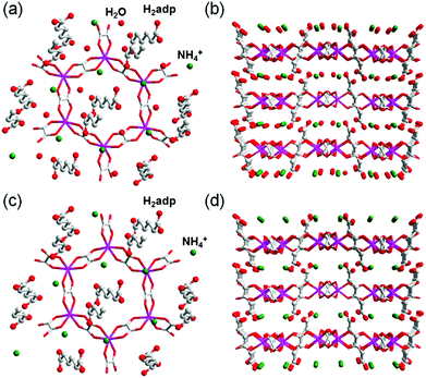 |
| | Fig. 3 Crystal structures of dihydrate and anhydrate phases. Honeycomb layer structure of (a) dihydrate and (c) anhydrate. The layered structure of (b) dihydrate and (d) anhydrate. Red, gray, green, and blue colors correspond to O, C, N, and Zn atoms, respectively. Reproduced from ref. 48 with permission from American Chemical Society, Copyright 2014. | |
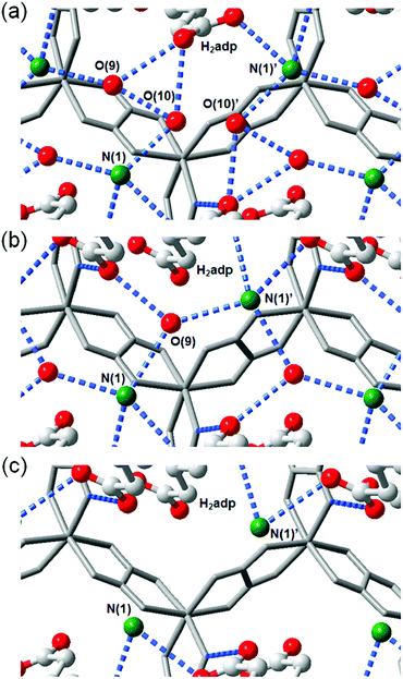 |
| | Fig. 4 Representation of H-bonding networks in (a) trihydrate, (b) dihydrate, and (c) anhydrate. Reproduced from ref. 48 with permission from American Chemical Society, Copyright 2014. | |
Another example of an oxalate-bridged MOF including a carboxylic acid group and water molecules, {NR3(CH2COOH)}–[MaMb(ox)3]·nH2O (R = Et (ethyl) or Bu (n-butyl), MaMb = MnCr, FeCr, or FeFe, abbreviated as R–MaMb) was reported by Ōkawaet al. in 2012 (Fig. 5).49 On the cationic components, the carboxylic acid group was located in the interlayer space to give additional protons. Adsorption measurements revealed that the water molecules (n = 0.5–4, depending on the hydrophilicity of the cationic component) were also present in the pores of the MOF (Fig. 5), but the positions of the water molecules were not determined using SCXRD. The effect of the hydrophilicity of the cationic components on the proton conduction properties was systematically studied. The proton conductivity completely depended on the type of cation (Fig. 6). According to the adsorption measurements, the hydrophilic compounds, i.e., those with a large number of water molecules in the interlayer space, showed a higher proton conductivity than the others. The most hydrophilic compound, Et–FeCr, showed the highest proton conductivity above 10−4 S cm−1 (25 °C, 80% RH). By contrast, the hydrophobic compound, Bu–FeCr, does not show high proton conduction under the same conditions. The relationship between water adsorption and proton conductivity in the same framework structure clearly suggested that the H-bonding network in the pore plays a critical role for high proton conduction.
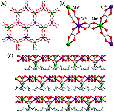 |
| | Fig. 5 The crystal structure of {NR3(CH2COOH)}–[MCr(ox)3]·nH2O. (a) Representation of the coordination geometry around MnII and CrIII, (b) the honeycomb layer structure, and (c) stacking view along the layers. Reproduced from ref. 49 with permission from American Chemical Society, Copyright 2012. | |
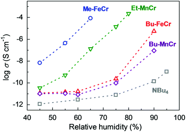 |
| | Fig. 6 Humidity dependence of the proton conductivity at 298 K. The blue, green, red, purple, and gray colors correspond to the proton conductivity of Me–FeCr, Et–MnCr, Bu–FeCr, Bu–MnCr, and NBu4, respectively. Reproduced from ref. 49 with permission from American Chemical Society, Copyright 2012. | |
Shigematsu et al. reported on the proton conductivity of MIL-53 derivatives, [M(OH)(bdc–R)] (M3+ = Al3+ or Fe3+; bdc2− = 1,4-benzenedicarboxylate; –R = –COOH, –H, –NH2, –OH), having different functional groups such as carboxylic acid, amino, and hydroxyl groups.37 Other derivatives of the 1,4-benzenedicarboxylic acid (bdc) ligands, having various functional groups, can be introduced without major structural changes of the MIL-53 framework. These functional groups are arranged along the one-dimensional (1-D) channels of MIL-53, which can include water molecules (Fig. 7). Then, in the 1-D channel, an additional proton from the acidic functional group, such as –COOH, can be accepted by the included water molecules to form the H3O+–H2O system in the pores. These compounds show proton conductivity in range of 10−8–10−5 S cm−1 under high humidity (95% RH) at ambient temperatures (298–353 K). The conductivity completely depends on the functional groups. The carboxylic acid-functionalized MIL-53 showed the highest conductivity, around 10−5 S cm−1, suggesting that the concentration of the additional protons in the pores depends on the pKa of the functional groups. The activation energies of these compounds are estimated to be 0.47–0.21 eV, which suggests that the proton conduction in these compounds mainly occurs through the Grotthuss-type mechanism.
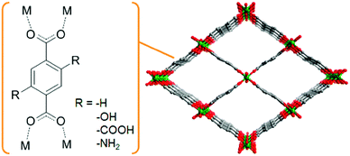 |
| | Fig. 7 Schematic view of the basic framework structure of MIL-53. | |
The sulfonic acid group is one of the most acidic functional groups, having a relatively low pKa of less than 0, meaning that if water molecules coexist, H3O+ ions are stoichiometrically formed from the sulfonic acid group. Because the concentration of additional protons in H3O+–H2O is directly related to proton conductivity, the introduction of sulfonic acid is an ideal way to increase proton conductivity compared with a weak acid such as carboxylic or phosphonic acid. Phang et al. reported the introduction of the sulfonic acid group into the pores of a UiO-66 framework in 2015 (Fig. 8).36 A post-synthetic method was used to obtain the sulfonic acid-functionalized UiO-66 (UiO-66–(SO3H)2). Oxidation of thiol-functionalized UiO-66 (UiO-66–(SH)2) was performed with H2O2 under hydrothermal conditions to give UiO-66–(SO3H)2. Note that UiO-66 and its derivatives are quite stable even under highly acidic conditions.50 UiO-66–(SH)2 shows a moderate proton conductivity of 2.5 × 10⁻⁵ S cm−1. However, after the post-synthetic reaction, UiO-66–(SO3H)2 shows a superprotonic conductivity of 0.84 × 10⁻¹ S cm−1 at 80 °C under humidified conditions (90% RH), which is much higher than that of other proton conductors having carboxylic acid (∼10−3 S cm−1) and phosphoric acid groups (∼10−2 S cm−1). The activation energy of UiO-66–(SO3H)2 is estimated to be 0.32 eV, suggesting the existence of the Grotthuss-type mechanism in this system, while the exact positions of the adsorbed water molecules were not determined.
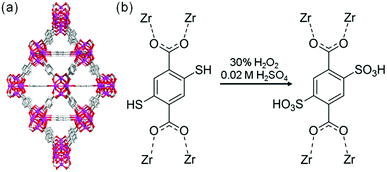 |
| | Fig. 8 (a) Crystal structure of UiO-66. (b) Scheme of the post-synthetic modification of UiO-66(SH)2 to introduce sulfonic acid groups. | |
2.2. Hydroxide ions with water molecules
The hydroxide ion (OH−) also has potential for constructing a degenerate system with water molecules (the OH−–H2O system) because of the capability of proton “back” transfer from H2O to OH− for the migration of the OH− ionic carrier. In fact, the existence of the OH−–H2O degenerate system in the water solvent was revealed by Tuckerman et al. in 2002 using MD simulation (Fig. 9).51 The OH− ion shows abnormally high mobility in water (20.6 m2 s−1 V−1),45 which is slightly lower than that of a proton (H+: 36.2) and much higher than that of other ions (e.g., Li+: 4.0), meaning that the OH− ion carrier potentially shows high ionic conductivity with water molecules. In the field of MOFs, OH− ion inclusion was believed to be difficult because of the corrosive nature of the OH− ions. Thus, MOFs seemed not to be good host materials for OH− ions. However, recently, OH− ions were successfully incorporated using some alkaline-stable MOFs, and their conductivity has been studied.52,56
 |
| | Fig. 9 Schematic illustration of the migration of OH− ions with water solvent. Reproduced from ref. 51 with permission from Nature Publishing Group, Copyright 2002. | |
In 2014, Sadakiyo et al. reported a basic design of OH ion-conductive MOFs. They proposed different types of MOFs that include the OH− ion. Type A introduces the OH− ions using cationic frameworks, while type B introduces hydroxide salts into the pores. They demonstrated a type B hydroxide ion-conducting MOF, (NBu4)m(A)n{Zn(mim)2}6 (Hmim = 2-methylimidazole; A = anions) (e.g., OH−(NBu4-ZIF-8-OH)), synthesized through a salt inclusion reaction using an alkaline-stable MOF (Fig. 10).52 ZIF-8 (ref. 53) was used as a mother framework to incorporate the hydroxide ion salt of NBu4OH into the pore of the MOF. NBu4-ZIF-8-OH has an ionic conductivity of 2.3 × 10⁻⁸ S cm−1 (99% RH, 25 °C), with 10−12 S cm−1 for the blank ZIF-8. From water adsorption measurements, the conductivity of NBu4-ZIF-8-OH is derived from both OH− and H2O, suggesting the existence of an OH−–H2O system in the pore. The activation energy was estimated to be 0.7 eV, which is much higher than that of hydrated OH− ions (<0.2 eV),54 and might be attributed to the small apertures in ZIF-8. A type A hydroxide-ion conductor was also reported by Nagarkar et al. in 2016.55 They reported a cationic MOF [Ni2(m-pymca)3]OH·nH2O that includes OH− ions as a counter ion together with water molecules in the pores (Fig. 11). The crystalline O atoms of H2O or OH− ions in the 1-D channel were determined by SCXRD, showing an H-bonding network between them. Thus, the OH−–H2O system should exist in the 1-D channel. This MOF showed a high ionic conductivity of 0.8 × 10⁻⁴ S cm−1 (99% RH, 27 °C) at ambient temperatures. They also showed a large difference in conductivities under H2O and D2O, which indicates that a proton transfer process is included in the ionic conduction in this system. The activation energy was estimated to be 0.19 eV, which is quite a low value as in the case of proton conduction by the Grotthuss mechanism, implying that the OH− ion conduction in this system occurs by a Grotthuss-like mechanism, i.e., a proton “back” transfer along the H-bonding network.
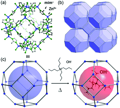 |
| | Fig. 10 Representation of the crystal structure of ZIF-8 (ref. 53) and a schematic image of salt inclusion. (a) Cage and (b) 3-D porous SOD structures of ZIF-8. (c) Schematic view of the preparation procedure for NBu4-ZIF-8-OH. Reproduced from ref. 52 with permission from American Chemical Society, Copyright 2014. | |
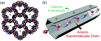 |
| | Fig. 11 (a) Crystal structure of [Ni2(m-pymca)3]OH·nH2O along the channel. (b) Schematic representation of a cationic MOF with an anionic supramolecular chain of hydroxide anions and water molecules inside the MOF pore for efficient hydroxide ion conduction. Reproduced from ref. 55 with permission from Royal Society of Chemistry, Copyright 2016. | |
Another example was reported by Li et al. in 2017.56 Free OH− ions together with various cations (i.e., NBu4 and [EVIm] (EVIm = 1-ethyl-3-vinylimidazolium)) were incorporated into a charge-neutral MOF (Fig. 12), [Cu6(NDI)3]·guest (FJU-66, H2NDI = 2,7-bis(3,5-dimethyl)dipyrazol-1,4,5,8-naphthalene-tetracarboxydiimide). FJU-66 showed extremely high stability under alkaline conditions at around pH 14 and thus could be used as an alkaline-stable mother framework. The conductivity of FJU-66 with the hydroxide salt completely depends on the included salts and is in the range from 10−7 to 10−2 S cm−1 at 30 °C under 95% RH. FJU-66[EVIm]OH showed the highest conductivity of 5.7 × 10⁻² S cm−1 with a very low activation energy of 0.11 eV, suggesting that ionic conduction occurs through a Grotthuss-like mechanism using the proton back transfer.
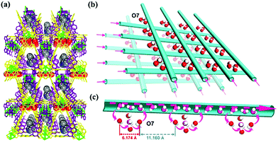 |
| | Fig. 12 Ionic transport pathway of FJU-66[EVIm]OH. (a) Packing view of FJU-66[EVIm]OH along the a direction. (b) Packing view of the available water pathways in FJU-66 along the a and b directions. (c) Possible supramolecular chain formed by OH− anions and water molecules inside the channel of FJU-66 for efficient OH ion conduction. Reproduced from ref. 56 with permission from American Chemical Society, Copyright 2017. | |
3. Ammonia-based degenerate system for proton conduction in MOFs
The pore of MOFs is a useful space for the encapsulation of small molecules such as gases, organic molecules, and proton-conducting media. In particular, NH3 adsorption in MOFs has been investigated for the storage of a renewable energy source with a high energy density, as well as removal of corrosive and toxic gases. In general, however, the presence of NH3 species is detrimental to most MOF compounds because NH3 can replace the existing ligand, resulting in structural decomposition. Nevertheless, the NH3 (NH4+) encapsulated in a pore can serve as an efficient proton conducting medium in MOFs because of its H-bonding ability. In addition, NH3 is able to generate a NH4+–OH− system with water molecules because of its high solubility. Meanwhile the degenerate system of NH4+–NH3 can be described as a coexistence of protonated NH3 and pure NH3. The mobility of NH4+ in the presence of NH3 is 0.94 ± 0.35 cm2 s−1 V−1,57 which is a lower value than that for other ions (H+, OH−, and Li+)45 in water. However, its H-bonding ability facilitates long range proton diffusion through the H-bond network. In this section, we deal with the stability of MOFs against NH3 and NH3 (NH4+)-mediated proton conductivity, and the dynamic behavior of NH3 (NH4+) in the pores of MOFs for proton conduction.
3.1. Stability of metal–organic frameworks against NH3
The structural stability of MOFs has been widely investigated with respect to thermal, chemical, and mechanical aspects because it is an important factor for various applications.50,51,58 In particular, the stability in the presence of water species is a crucial issue for real-world applications because water vapor exists in process environments such as natural gas streams, industrial flue gas, or pollutant separation.59 Moreover, the stability of MOFs toward hydrolysis is one of the key factors for proton-conductive MOFs. Like in a water system, NH3-mediated proton conductivity in MOFs can be affected by structural stability under the NH3 atmosphere because NH3 is able to work not only as a conducting medium, but also as a coordinating ligand. Fundamentally, the structural stability of MOFs against NH3 is estimated by the gas sorption isotherm and powder X-ray diffraction (PXRD) pattern analysis. The unstable MOFs indicate decreased porosity and surface areas with degradation of crystallinity, including peak broadening in PXRD patterns during the repeated NH3 adsorption–desorption process. Previously, MOFs constructed from Zn4O or Cu-paddlewheels as secondary building units (SBUs) have been reported to be unstable in NH3.60,61 By contrast, in most cases, there is no mention of structural stability for MOFs in NH3 sorption experiments. In 2014, Kajiwara et al. reported on a systematic stability study of various types of MOFs against NH3 gas (Table 1).62 They considered the effects of the metal cation species and type of organic linker. To check the stability of MOFs against NH3, degassed samples were loaded into an NH3 exposure system for 2 h at various temperatures and PXRD patterns were compared before and after NH3 exposure. Some MOFs that had high thermal stability decomposed at room temperature under the NH3 atmosphere. The metal center of MOFs is strongly related to stability. Specifically, the divalent metal cation is unstable under NH3, except for MOF-74 and ZIF-8. In addition, MOFs constructed from oxophilic metal cations, such as MIL-125(TiIV), UiO(ZrIV), MIL-103(TbIII), and MOF-76(LnIII), show a high stability toward NH3, whereas the less oxophilic InIII center is kinetically labile and reacts easily with the N of NH3. The most stable MOFs were derived from Al(III) and Cr(III) metal cations because of the inertness of the metal cation and oxophilicity. Furthermore, the ligand length and the metal–ligand bond strength are stability factors. Longer ligands weaken the structural stability because of the high void space generation. For ZIF-8, the anionic mim linker with a formal charge of −0.5 on each N atom has a stronger basicity than NH3 and is strongly bound to the metal center. Consequently, seven types of MOFs, such as MIL-53(Al), Al-BTB, MOF-76(M) (M = Y, Yb), MIL-101(Cr), ZIF-8, and MOF-74(Mg), which have an oxophilic MII center, chemically inert MIII center, chelate-type coordinating ligand, or anionic linker, showed high stability with NH3 up to 350 °C. These materials are also highly stable in water,63,64 which implies that the stability of MOFs against NH3 has a similar trend toward water. Considering the predictions for the deconstruction of MOFs by NH3, the decomposition mechanism is similar to that of water.60,65
Table 1 The results of the ammonia stability test for MOFs62
| Compounds |
Chemical formula (*)a |
T
d
[°C] |
Metal ion oxidation state |
Thermal stability with NH3c |
| RT |
200 °C |
300 °C |
350 °C |
|
MOFs with open metal sites are denoted with *.
Thermal decomposition temperature determined by TGA.
+, the structure is maintained; ±, partially decomposed; −, completely decomposed. Abbreviations of ligands: bpy = 4,4′-bipyridine (ND), for = formate (OD), mim = 2-methylimidazolate (ND), bdc = benzene-1,4-dicarboxylate (OD), bdpc = biphenyl-4,4′-dicarboxylate (OD), btc = benzene-1,3,5-tricarboxylate (OD), dobdc = 2,5-dioxidobenzene-1,4-dicarboxylate (OD), and btb = benzene-1,3,5-tris(4-benzoate) (OD). OD: oxygen donor; ND: nitrogen donor.
|
|
|
Cu2(bpdc)2(bpy) |
310 |
II |
− |
|
|
|
|
|
Zn3(bpdc)3(bpy) |
380 |
II |
− |
|
|
|
| HKUST-1 |
Cu3(btc)2* |
340 |
II |
− |
|
|
|
| MOF-5 |
Zn4O(bdc)3 |
420 |
II |
− |
|
|
|
|
|
Mg(for)2 |
430 |
II |
− |
|
|
|
| MIL-68(In) |
In(OH)(bdc) |
450 |
III |
− |
|
|
|
| MIL-125 |
Ti8O8(OH)4(bdc)6 |
360 |
IV |
+ |
+ |
− |
|
| UiO-66 |
Zr6O4(OH)4(bdc)6* |
470 |
IV |
+ |
+ |
− |
|
| UiO-67 |
Zr6O4(OH)4(bpdc)6* |
490 |
IV |
+ |
+ |
− |
|
| MIL-103(Tb) |
Tb(btb)* |
490 |
III |
+ |
+ |
− |
|
| MOF-74(Ni) |
Ni2(dobdc)* |
340 |
II |
± |
± |
± |
± |
| MOF-74(Mg) |
Mg2(dobdc)* |
390 |
II |
+ |
+ |
+ |
+ |
| MOF-74(Zn) |
Zn2(dobdc)* |
430 |
II |
+ |
+ |
± |
± |
| MOF-76(Tb) |
Tb(btc)* |
470 |
III |
+ |
+ |
+ |
− |
| MOF-76(Y) |
Y(btc)* |
>500 |
III |
+ |
+ |
+ |
+ |
| MOF-76(Yb) |
Yb(btc)* |
>500 |
III |
+ |
+ |
+ |
+ |
| DUT-5 |
Al(OH)(bpdc) |
>500 |
III |
+ |
+ |
± |
− |
| MIL-53(Al) |
Al(OH)(bdc) |
>500 |
III |
+ |
+ |
+ |
+ |
| MIL-101(Cr) |
Cr3O(OH)(bdc)3* |
390 |
III |
+ |
+ |
+ |
+ |
| Al-BTB |
Al(btb) |
>500 |
III |
+ |
+ |
+ |
+ |
| ZIF-8 |
Zn(mim)2 |
>500 |
II |
+ |
+ |
+ |
+ |
Rieth and Dinca reported in 2018 on NH3 adsorption capacity, kinetics, and structural stability against NH3 for isoreticular MOFs.66 They synthesized M2Cl2BTDD and M2Cl2BBTA, which have different pore sizes achieved by ligand extension (Fig. 13, M = Co, Ni, Cu; BTDD = bis(1H-1,2,3-triazolo[4,5-b],[4′,5′-i])dibenzo[1,4]dioxin; BBTA = 1H,5H-benzo(1,2-d),(4,5-d′)bistriazole). Among the three metal species, Ni2+ compounds are most stable toward NH3. Ni2Cl2BBTA with a small pore (13 Å) is only an example that retains its surface area after 1 bar of NH3 treatment, and Ni2Cl2BTDD with a large pore (23 Å) withstands pore filling with NH3 exhibiting a diminished surface area. However, Co2+ compounds cannot withstand pore filling of NH3 (1 bar of NH3), and both Cu2+ compounds are unstable even at low NH3 concentrations. This stability trend is attributed to the kinetic metal–aquo substitution rate because Ni2+ is approximately kinetically four orders of magnitude more inert than Cu2+ and two orders of magnitude more inert than Co2+ (Ni2+ > Co2+ > Cu2+). As a relevant stability parameter, this type of kinetic stability has been applied in a previous study to explain the robustness of isostructural frameworks such as MIL-100(Cr3+), MIL-54 (Al3+), and −47 (V4+) MOFs. The robustness was in the order of Cr3+ > Al3+ > V4+.67 According to previous studies, undoubtedly, the structural stability of MOFs toward NH3 has a strong relationship with their stability in water. Therefore, an increased metal–ligand bond strength provides the chemical robustness of MOFs. One of the strategies for improving stability—although it is synthetically challenging—is the incorporation of kinetically inert and oxophilic metal species into the framework. Future endeavors in this direction are expected to be beneficial for producing durable MOFs materials to NH3. The next section describes and discusses the proton conductivity of NH3 (NH4+) encapsulated in a representative set of MOFs.
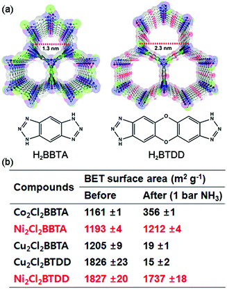 |
| | Fig. 13 (a) MOF structures based on H2BTDD (left) and H2BBTA (right) ligands. (b) Brunauer–Emmett–Teller (BET) surface area change after NH3 exposure. Reproduced from ref. 66 with permission from American Chemical Society, Copyright 2018. | |
3.2. NH3 (NH4+) as a proton-conducting medium in MOFs
For water molecules, known as the most efficient conducting medium, the conjugate acid (H3O+) and base (H2O) play a crucial role in the proton diffusion path. Likewise, the conjugate acid–base of NH3 is an interesting proton conduction path. In general, the proton conductivity of NH3 has been investigated at a low temperature (<bp: 240 K) because of the gas phase problem. However, the use of porous frameworks allows NH3-mediated conductivity to be studied in a wide temperature range above and below room temperature, where NH3 can be encapsulated in pores as NH4+ or NH3 forms. The major examples of NH3-based proton conduction systems reveal NH4+–H2O-mediated proton conductivity rather than a NH4+–NH3 degenerate system. In this section, therefore, the proton conductivity in MOFs through NH3 (NH4+) species is discussed focusing on the incorporation methods of NH3 (NH4+) species for proton conductivity.
3.2.1 Encapsulation of NH4+ in MOFs as a counterion.
For structural neutrality, some MOFs incorporate a counter ion species as a lattice component during the synthetic process.32–35,47,68–70 In particular, protic counterions (H3O+ or NH4+) included in pores for charge compensation can serve as proton carriers. As mentioned above, oxalate-bridged 2-D honeycomb sheets of [Zn2(ox)3]2−, (NH4)2(H2adp)[Zn2(ox)3]·3H2O (H2adp = adipic acid) show a superprotonic conductivity of 10−2 S cm−1 with NH4+ species.47
The role of NH4+ species in proton conductivity has been proven by metal cation substitution (Fig. 14).71 Sadakiyo et al. reported in 2014 on K2(H2adp)[Zn2(ox)3]·3H2O, where the NH4+ of (NH4)2(H2adp)[Zn2(ox)3]·3H2O was replaced by K+ without an apparent structural change. For K2(H2adp)[Zn2(ox)3]·3H2O, the H bonds in the ox ion and H2adp (O(1)⋯O(7), 2.678(2) Å); between H2adp and water molecules (O(7)⋯O(10), 3.043(4) Å and O(7)⋯O(9), 3.122(3) Å); and between water molecules (O(9)⋯O(10), 2.711(7) Å) are closed to those of (NH4)2(H2adp)[Zn2(ox)3]·3H2O. This implied that the counterion exchange is not affective in a guest molecule arrangement. However, a remarkable difference is the non-hydrogen bonding of the K+ ion instead of the H-bonding NH4+, despite the nearly identical position (Fig. 14). The absence of H-bonding associated with NH4+ provided a lower proton conductivity (1.2 × 10⁻⁴ S cm−1 at 25 °C, under 98% RH) by approximately two orders of magnitude compared with that of NH4+. These results strongly suggest that the NH4+ medium is crucial not only for increasing proton carrier concentration by acidic character (pKa = 9.2), but also for facilitating proton transfer by forming H bonding with neighboring molecules.
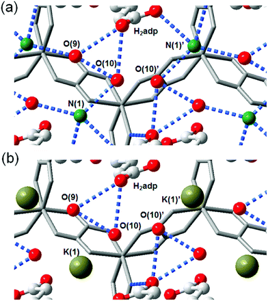 |
| | Fig. 14 Comparison of H-bonding networks by ion substitution. (a) (NH4)2(H2adp)[Zn2(ox)3]·3H2O. (b) K2(H2adp)[Zn2(ox)3]·3H2O. Reproduced from ref. 71 with permission from American Chemical Society, Copyright 2014. | |
In 2011, Pardo et al. reported an oxalate-bridged bimetallic 3-D chiral anionic network including NH4+ species with the formula (NH4)4[MnCr2(ox)6]·4H2O (Fig. 15).72 In the framework, two types of oxalate ligands are observed. One of them shows the uncoordinated O of the oxalate ligand, which is directed toward ordered water molecules in channel A along the helical c-axis. Another oxalate ligand links Cr(III) to Mg(II) ions in a bis-bidentate way. The counterions (NH4+) and the guest molecules (H2O) are located around the oxalate network in the A channel, giving rise to high proton conductivity at room temperature. In the two types of channels (A and B), the A channel, decorated by the terminal O of oxalate, has a well-defined helical chain of ammonium cations [N⋯N = 2.839(7)–2.892(6) Å], indicating H-bonding networks with the O atoms of the terminal oxalates [N⋯O = 2.795(6)–2.960(8) Å]. Although water molecules are present in both pores, the water molecules in channel A, stabilized by the terminal oxalate O with an H-bonding network, are only refined. As humidity increases, the σ value is enhanced by five orders of magnitude from 2.4 × 10⁻⁹ S cm−1 at 9% RH to 1.1 × 10⁻³ S cm−1 at 96% RH, which improved to 1.7 × 10⁻³ S cm−1 at 313 K. The activation energy (Ea) for the ionic conductivity estimated from the Arrhenius plot is 0.23 eV (Fig. 15b inset). These results imply that the high proton conductivity is derived from an efficient H-bonding network through the Grotthuss mechanism. They believed that the A channel that included H-bonding networks among the terminal oxalate, NH4+ cations, and ordered H2O molecules is an attractive potential pathway for the proton conduction triggered by humidity.
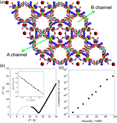 |
| | Fig. 15 (a) Structure of (NH4)4[MnCr2(ox)6]·4H2O. NH4+ counterion and H2O guest molecules are represented as a sphere. Red, green, gray, cyan, and blue correspond to oxygen, chromium, carbon, manganese, and nitrogen atoms, respectively. (b) Cole–Cole semicircle plot at 295 K and 96% RH. (c) RH dependence of σ for (NH4)4[MnCr2(ox)6]·4H2O at 295 K. Reproduced from ref. 72 with permission from American Chemical Society, Copyright 2011. | |
3.2.2 Aqueous-NH3 inclusion in MOFs.
Aqueous NH3 (ammonia water) is a solution of NH3 in water. Recently, a few results have been reported for the proton conductivity of MOFs using various concentrations of aqueous NH3 solution vapor instead of pure water vapor.73–75 In 2014, Bazaga-García et al. reported the enhanced proton conductivity of a calcium phosphonate framework through post-synthetic modifications using aqueous NH3.73 The calcium phosphonate framework was constructed from Ca2+ ions and the rigid polyfunctional ligand 5-(dihydroxyphosphoryl) isophthalic acid (PiPhtA), giving the formula Ca2[(HO3PC6H3COOH)2]2[(HO3PC6H3(COO)2H)(H2O)2]·5H2O, Ca-PiPhtA-I. Ca-PiPhtA-I has a high water content in the Ca2+ metal centre (two water molecules coordinated) and a 1-D channel (five lattice water molecules). In this pillared layered structure, the hydrophilic 1-D channel is observed along the b-axis, which is filled with five lattice water molecules per unit cell. The lattice water molecules exhibit water-to-water interactions providing an extended H-bond network along the 1-D channels as a potential proton transfer pathway. The removal of the five lattice water molecules at 75–130 °C indicated a partially dehydrated structure (Ca-PiPhtA-II, Fig. 16b). To include the NH3 species in the pore, Ca-PiPhtA-I was exposed to 28% aqueous NH3 solution, resulting in the inclusion of 7NH3 and 16H2O molecules in Ca-PiPhtA-NH3. However, a detailed structural analysis of Ca-PiPhtA-NH3 is impossible because of the lack of crystallinity with a partial structure decomposition. The IR spectrum of Ca-PiPhtA-NH3 reveals that the water stretching vibrational signal shifts to a lower wave number, implying the presence of a strong H bond. Interestingly, the dehydrated sample does not take up NH3 in NH3-temperature programmed desorption (TPD) measurements, which means that NH3–H2O adsorption occurred through the cooperative mechanism of H-bonding interactions. The proton conductivity values for Ca-PiPhtA-I and Ca-PiPhtA-II were 5.7 × 10⁻⁴ and 3.6 × 10⁻⁴ S cm−1 at 24 °C and 98% RH, respectively. These values increased up to 1.3 × 10⁻³ S cm−1 at 40 °C (water-equilibrated state was called Ca-PiPhtA-III). However, the conductivity value was not retained at high temperatures (>45 °C) because of the dehydration process. Ca-PiPhtA-NH3 represented a maximum value of σ (6.6 × 10⁻³ S cm−1) at 24 °C and 98% RH. The activation energies (Ea) for the proton transfer in Ca-PiPhtA-I (0.32 eV), Ca-PiPhtA-III (0.23 eV), and Ca-PiPhtA-NH3 (0.40 eV) are in the range of those of the Grotthuss mechanism.
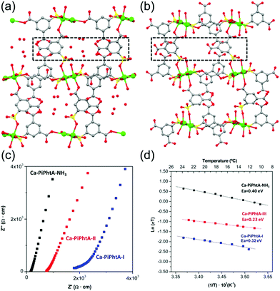 |
| | Fig. 16
b-axis view (a-axis horizontal) of the crystal structures of Ca-PiPhtA-I (a) and Ca-PiPhtA-II (b) showing the slightly different conformation of the 1-D channels along the c axis. (c) Plot of the complex impedance plane of Ca-PiPhtA compounds at 24 °C and 98% RH. (d) Arrhenius plots vs. T−1 from 10 to 24 °C. Reproduced from ref. 73 with permission from American Chemical Society, Copyright 2014. | |
Liang et al. investigated in 2014 the difference in proton conductivity in water and various concentrations of the aqua NH3 medium. They used two 3-D CoII MOFs, {[Co3(m-ClPhIDC)2(H2O)6]·2H2O}n [1; m-ClPhH3IDC = 2-(m-chlorophenyl)imidazole-4,5-dicarboxylic acid] and {[Co3(p-ClPhHIDC)3(H2O)3]·6H2O}n (2; p-ClPhH3IDC = 2-(p-chlorophenyl)imidazole-4,5-dicarboxylic acid) (Fig. 17).74 The two compounds have a similar 1-D channel system and different water contents (coordinating six and two free water molecules for 1 and coordinating three and six free water molecules for 2). Furthermore, these compounds are highly stable while soaking in water and in boiling water, or under treatment with 7.4 M NH3·H2O solution vapor without structural change. However, the crystal structures and guest composition of the aqueous NH3-treated samples were not given. The conductivity of compound 1 under humid conditions (98% RH, 30 °C) was 2.73 × 10⁻⁶ S cm−1 and increased to 7.62 × 10⁻⁴ S cm−1 at 100 °C with an activation barrier of 1.58 eV. By contrast, compound 2 showed a maximum proton conductivity of 2.47 × 10⁻⁴ S cm−1 at 90 °C and 98% RH. For further enhanced proton conductivity, the two MOFs were exposed to different concentrations of aqua-NH3 vapor from 2.11 to 7.40 M. As the NH3 concentration increased to 7.40 M, the conductivity values of the two MOFs increased by two orders of magnitude, from 7.44 × 10⁻⁷ to 4.39 × 10⁻⁵ S cm−1 for 1 and from 5.71 × 10⁻⁷ to 4.23 × 10⁻⁵ S cm−1 for 2. At 100 °C with a concentration of 7.4 M, these MOFs have a superionic conductivity of 2.89 × 10⁻² and 4.25 × 10⁻² S cm−1, respectively. Obviously, both factors, a high concentration of aqua NH3 vapor and temperature, are beneficial for proton conduction. The activation energy barrier of compound 1 at an NH3–H2O concentration of 4.93 M was changed from 0.25 eV at 30–60 °C to 0.73 at 70–100 °C, which means that proton-hopping diffusion is favorable through the H-bonding networks at low temperatures (<60 °C), and that the vehicular transfer motion of NH4+ and H3O+ is dominant at high temperatures (>60 °C). The enhanced conductivity triggered by the aqueous–NH3 vapor originated from protonation of the conducting medium and the H-bonding ability of NH4+ with a synergistic effect on the proton conduction process. However, for an intuitive understanding of the proton conduction mechanism, obtaining a convincing structure for NH3 confined in MOFs remains challenging.
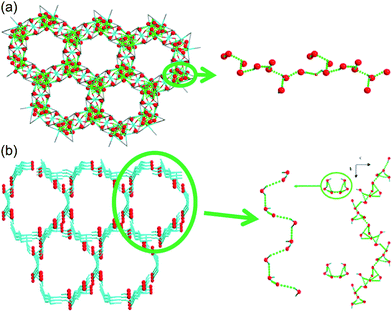 |
| | Fig. 17 1-D channels with water molecules in (a) {[Co3(m-ClPhIDC)2(H2O)6]·2H2O}n (1) and (b) {[Co3(p-ClPhHIDC)3(H2O)3]·6H2O}n (2). Red spheres represent O atoms in water, and green dots present H-bonding networks. Reproduced from ref. 74 with permission from American Chemical Society, Copyright 2017. | |
3.2.3 Additional protonation to anhydrous NH3 in MOFs.
Previous studies have demonstrated NH3 (NH4+)-mediated proton conductors through the simultaneous introduction of the NH4+ counterion during MOF synthesis or aqueous-NH3 vapor loading exhibiting an improved proton conductivity. Anhydrous NH3-mediated proton conductivity was reported recently using MIL-53(Al) derivative MOFs through pure NH3 gas adsorption.76 MIL-53 (Al) derivatives that are well known for their high stability are synthesized from AlIII ions and H2bdc ligands with various functional groups, (H2bdc–(COOH)2, 1), (H2bdc–(NH2), 2), (H2bdc–(OH), 3), and (H2bdc, 4), indicating the difference in proton-donating ability (pKa). All samples are stable under 100 kPa of NH3. In NH3 adsorption–desorption measurements, compound 1 adsorbed two more additional equivalents of NH3 than the other compounds because of the acid–base reaction by the dangling two carboxylic acid groups in the ligand (Fig. 18a). This implies that NH3 can exist as NH4+ species, which is confirmed by IR spectroscopy, XPS, and solid-state 2H NMR. The crystal structures incorporating NH3 molecules were determined by Rietveld refinement analysis of PXRD, which shows the formation of an H-bonding network among the NH3, the framework (μ-OH and the functional group of the ligand), and the adjacent NH3 (Fig. 18c and f). The confined NH3 guests are aligned in a zigzag shape along the 1-D channels, and the distance of adjacent NH3 was shortened with decreased acidity of the functional group because of the reduced attraction from the pore wall. Meanwhile, NH3 molecules confined in MIL-53(Al)–(COOH)2 are well distributed in the overall framework with a strong interaction supported by NH3-TPD. Proton conductivity was measured by using an in situ system with controlled pure NH3 gas pressure. The initial low conductivity values of the four compounds under vacuum at 298 K (1.2 × 10⁻¹², 2.8 × 10⁻¹³, 1.1 × 10⁻¹³, and 6.6 × 10⁻¹³ S cm−1) markedly increased up to 4.9 × 10⁻⁷, 1.0 × 10⁻⁹, 4.2 × 10⁻⁹, and 9.1 × 10⁻¹¹ S cm−1 for 1, 2, 3, and 4, respectively, as the NH3 pressure increased to 100 kPa (Table 2). The small change in the NH3 pressure and pore environment by the functional group triggers a large change in the conductivity. As expected, the acid functional group in the ligand strongly affects the proton conductivity and the simultaneous formation of NH4+ species plays a key role in a degenerate NH4+ + NH3 ⇔ NH3 + NH4+ proton diffusion pathway. Under the saturated NH3 pressure at 290 K, the conductivity of compound 1 became 2.56 × 10⁻⁵ S cm−1, which is comparable to the anhydrous proton conductivity in MOFs. The activation energy for proton conduction in compound 1 estimated by using the Arrhenius plot under NH3 saturated pressure at various temperatures is 0.46 eV. These results are the first report of anhydrous NH3-mediated proton-conductive MOFs with crystallographic analysis.
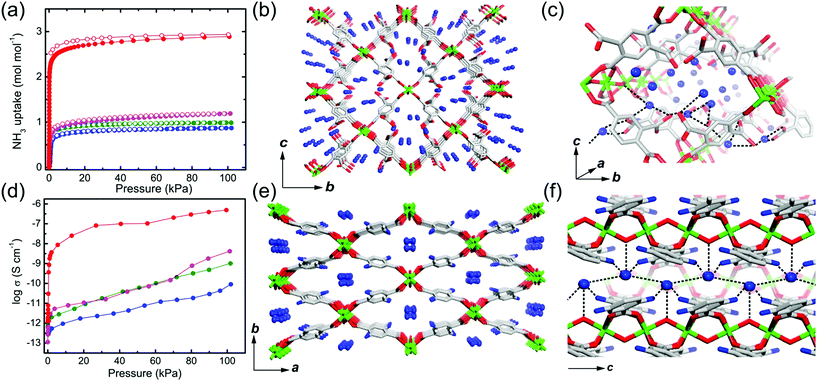 |
| | Fig. 18 NH3 adsorption–desorption isotherm, structure of NH3@MIL-53(Al) derivatives, and proton conductivity. (a) NH3 adsorption–desorption profiles at 298 K and 100 kPa. The different colors represent MIL-53(Al) derivatives (–(COOH)2, red; –NH2, green; –OH, pink; –H, blue). (b and c) Crystal structures of NH3@MIL-53(Al)–(COOH)2 and (e and f) NH3@MIL-53(Al)–(NH2). (d) NH3 pressure dependence of proton conductivity in MIL-53(Al) derivatives. Reproduced from ref. 76 abiding by the terms of the license from Chemrxive, Copyright 2018. | |
Table 2 NH3-mediated proton conductivity of MIL-53(Al) derivatives76
| Compounds |
NH3 uptake amountsa (mole per mole) |
Conductivity (S cm−1) |
| In a vacuum |
100 kPa NH3 |
|
298 K and 100 kPa.
|
| MIL-53(Al)–(COOH)2 |
2.9 |
1.2 × 10⁻¹² |
4.9 × 10⁻⁷ |
| MIL-53(Al)–NH2 |
1.0 |
2.8 × 10⁻¹³ |
1.0 × 10⁻⁹ |
| MIL-53(Al)–OH |
1.2 |
1.1 × 10⁻¹³ |
4.2 × 10⁻⁹ |
| MIL-53(Al) |
1.0 |
6.6 × 10⁻¹³ |
9.1 × 10⁻¹¹ |
3.3. Dynamic behavior of NH4+ for proton conductivity in MOFs
Molecular dynamics (MD) is one of the interesting topics regarding porous MOFs. Molecules located in the pore interact with a framework and exhibit a unique behavior. Indeed, the dynamic behavior of the conducting medium incorporated in porous materials helps in understanding the proton conduction mechanism. In particular, quasi-elastic neutron scattering (QENS) and solid-state NMR are powerful tools for investigating the dynamic molecular motion of protic species because the H atom has a larger incoherent neutron-scattering cross section (σinc = 80b, 1 b = 10−24 cm2) compared with other atoms such as C (σinc = 0b), N (σinc = 0.5b), O (σinc = 0b), and D (σinc = 2.1b), and NMR is a selectively sensitive probe for local MD. Therefore, the dynamic motions of all species containing an H atom can be selectively detected through incoherent neutron scattering and NMR.
In 2014, Miyatsu et al. clarified the relationship between proton conductivity and the phase transition associated with the dynamic behavior of NH4+ and water molecules in 2-D (NH4)2(H2adp)[Zn2(ox)3]·3H2O and K2(H2adp)[Zn2(ox)3]·3H2O.77 To measure neutron scattering, the methylene H atoms of adipic acid in (NH4)2(H2adp)[Zn2(ox)3]·3H2O and K2(H2adp)[Zn2(ox)3]·3H2O were deuterated to reduce their contribution to the scattering signal. Therefore, the major signals originated from NH4+, H2O, and carboxylic acid. QENS measurements were carried out using three neutron spectrometers (AGNES, IRIS, and HFBS) with different energy resolutions to cover a time range between 0.1 ps and 10 ns. In the adiabatic calorimetry experiment, (NH4)2(H2adp)[Zn2(ox)3]·3H2O and K2(H2adp)[Zn2(ox)3]·3H2O showed different phase transition temperatures at 86 and 138 K, respectively. Neutron powder scattering showed changes in the Bragg peaks located at Q = 1.60–1.64 A−1 and Q = 1.67–1.70 A−1 at the transition temperatures (Fig. 19). Compared with K2(H2adp)[Zn2(ox)3]·3H2O, (NH4)2(H2adp)[Zn2(ox)3]·3H2O indicated a more dramatic change. We note that SCXRD did not provide a significant structural change between 50 and 100 K because of the difficulty of detecting H atoms in X-rays. This means that the phase transition originated from H atoms. Relaxational dynamics were studied by QENS measurements. The dynamic structure factor S(Q, ω) was fitted to the following equations (Fig. 20a):
| | | S(Q, ω) = R(Q, ω) ⊗ {δ(ω) + ∑Li(Q, ω)} + BG | (3) |
| |  | (4) |
where
Li(
Q,
ω) describes the relaxation of H atoms and
Γ(
Q) is the half-width at half-maximum of the Lorentz function. The relaxation
Γ(
Q) is independent of
Q, which means that the motions of H atoms had a local origin. The Arrhenius plot of the relaxation time in
Fig. 20b shows four relaxation modes (
Ea = 2.3, 4.5, 7.7, and 12.9 kJ mol
−1 for L
1, L
2, L
3, and L
4, respectively) in (NH
4)
2(adp)[Zn
2(ox)
3]·3H
2O and only two relaxation modes (L
K1 and L
K2) in K
2(adp)[Zn
2(ox)
3]·3H
2O. The L
K1 and L
K2 modes were observed around L
3 and L
4, which means that four modes (L
3, L
4, L
K1, and L
K2) were derived from water molecules, whereas the L
1 and L
2 motions having a low activation energy are associated with NH
4+. The H bonds of NH
4+ were weaker than that of water and indicated low activation energy. The geometrical information of the two relaxation modes for NH
4+, L
1, and L
2 was studied through the relative integrated intensities of the elastic incoherent structure factor (EISF) (
Fig. 20c). The incoherent scattering reflects only the H atom motion in NH
4+ with a tetrahedral geometry because of the negligible incoherent scattering of the N atom. Among the several dynamic models, such as
C3 jump,
Td jump, and continuous rotation about the
C3 axis and
C2 axis, NH
4+ ions continuously rotate around the
C3 axis during the jumping motion between two preferred orientations. From these results, the phase transition and unique dynamic motion of NH
4+ for proton conduction could be clearly observed.
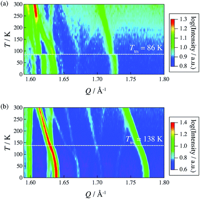 |
| | Fig. 19 2-D intensity maps obtained by neutron powder diffraction on IRIS for (a) (NH4)2(adp)[Zn2(ox)3]·3H2O and (b) K2(adp)[Zn2(ox)3]·3H2O. The intensity is given on a logarithmic scale. The white dashed line represents each transition temperature. Reproduced with permission from ref. 77 with permission from Royal Society of Chemistry, Copyright 2014. | |
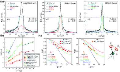 |
| | Fig. 20 (a) QENS profiles of (NH4)2(adp)[Zn2(ox)3]·3H2O obtained by using AGNES, IRIS, and HFBS spectrometers. (b) Arrhenius plot for the relaxation times of (NH4)2(adp)[Zn2(ox)3]·3H2O (filled symbols) and K2(adp)[Zn2(ox)3]·3H2O (open symbols) at Qav = 1.25 Å−1. (c) EISF of (NH4)2(adp)[Zn2(ox)3]·3H2O for the L1 mode measured by AGNES (left) and the L2 mode measured by IRIS (right). Solid curves represent the calculated EISF based on several model functions. Reproduced from ref. 77 with permission from Royal Society of Chemistry, Copyright 2014. | |
The dynamic motion and proton conduction mechanism of NH4+ confined in MIL-53(Al)–(COOH)2 were investigated by 2H solid-state NMR through line shape and spin-relaxation time analysis at various temperatures (Fig. 21).76 As mentioned above, pure NH3 molecules are converted to NH4+ by protonation from the dangling –(COOH)2 in the ligand. Furthermore, one of the NH3 molecules has an interaction with the μ2-OH bridge. These results are reflected in an anisotropic signal (Ia: coupling parameters, Qeff = 73 kHz, ηeff = 0; and Ib: Q0 = 223 kHz, η = 0.1, static ND4+) and an isotropic one (II, mobile ND4+). The anisotropic signal exhibits rapid rotational motion of static NH3 molecules around their C3 symmetry axis. In addition, restricted librations between μ-O–D–ND3 contributed to the larger coupling constant in the anisotropic signal. The isotropic signal originated from the complex isotropic reorientation and local internal rotational motion of mobile ND4+ with two distinct rotation mechanisms. All dynamic motions are shown in Fig. 21c. Although the major species of ND3 confined in the pore are the mobile ND4+ in the overall temperature range, a small fraction of static ND3 is present even at 313 K, implying a slow exchange rate between both species (<0.5 kHz). The equilibrium constant (Keq) derived from exp(ΔS/R)![[thin space (1/6-em)]](https://www.rsc.org/images/entities/char_2009.gif) exp(−ΔH/RT), where ΔS = 30.34 J mol−1 K−1 and ΔH = 3.4 kJ mol−1, coincides with the quantitative analysis of a relative population of two species through line-shape analysis. The T1 relaxation of the anisotropic signal shows a clear minimum (region a), whereas T1 of the isotropic signal exhibits flat-like behavior and a drastic increase in the high-temperature region (regions a′ and b′). This means that the mobile ND4+ has complex multiple motions in isotropic reorientation and an activation process mechanism change with the same geometrical motion. Considering the proton conduction mechanism, the local internal rotational motion of mobile ND4+ is responsible for the Grotthuss mechanism, resulting in the diffusion coefficient (D) evaluated from C3 axis rotation motion being 3.3 × 10⁻¹⁰ m2 s−1 with a 20 kJ mol−1 activation barrier. Furthermore, the high activation energy for proton conduction (0.46 eV) estimated from AC impedance measurements can account for the isotropic reorientation motion with random rotations, as well as the jump–diffusion process observed in region c′. The activation barrier of the related motion is 50 kJ mol−1, with a slow correlation time (τ = 3.6 × 10⁻⁵ s), which gives a low diffusion coefficient (1 × 10⁻¹⁵ m2 s−1) at 300 K. Although this is a lower diffusion coefficient value than that of the hopping mechanism, the value is acceptable considering the observed conductivity. The solid-state NMR measurement strongly supports the proton conduction mechanism predicted from the crystallographic analysis.
exp(−ΔH/RT), where ΔS = 30.34 J mol−1 K−1 and ΔH = 3.4 kJ mol−1, coincides with the quantitative analysis of a relative population of two species through line-shape analysis. The T1 relaxation of the anisotropic signal shows a clear minimum (region a), whereas T1 of the isotropic signal exhibits flat-like behavior and a drastic increase in the high-temperature region (regions a′ and b′). This means that the mobile ND4+ has complex multiple motions in isotropic reorientation and an activation process mechanism change with the same geometrical motion. Considering the proton conduction mechanism, the local internal rotational motion of mobile ND4+ is responsible for the Grotthuss mechanism, resulting in the diffusion coefficient (D) evaluated from C3 axis rotation motion being 3.3 × 10⁻¹⁰ m2 s−1 with a 20 kJ mol−1 activation barrier. Furthermore, the high activation energy for proton conduction (0.46 eV) estimated from AC impedance measurements can account for the isotropic reorientation motion with random rotations, as well as the jump–diffusion process observed in region c′. The activation barrier of the related motion is 50 kJ mol−1, with a slow correlation time (τ = 3.6 × 10⁻⁵ s), which gives a low diffusion coefficient (1 × 10⁻¹⁵ m2 s−1) at 300 K. Although this is a lower diffusion coefficient value than that of the hopping mechanism, the value is acceptable considering the observed conductivity. The solid-state NMR measurement strongly supports the proton conduction mechanism predicted from the crystallographic analysis.
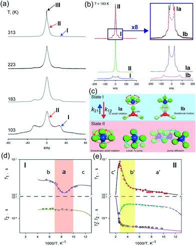 |
| | Fig. 21 (a) The temperature dependence 2H NMR of ND3 confined in the framework with three main components marked by arrows. (b) Line shape analysis for the ND3-saturated framework at 183 K: (top) experimental (black solid line) and full simulation (red dashed line); 8-times magnified spectra–experimental (black solid line) and full simulation (red dashed line); (bottom) simulation deconvolution into two main fractions: I (anisotropic) and II (isotropic); simulation deconvolution of the anisotropic fraction: Ia and Ib. (c) Dynamic motion of Ia: fast axial rotation, Ib: restricted libration, and II: isotropic reorientation including internal rotation, local Td jump and jump diffusion. (d and e) Spin–relaxation time (T1 and T2) for I and II. Reproduced from ref. 76 abiding by the terms of the license from Chemrxive, Copyright 2018. | |
3.4. Theoretical/computational study for the proton conduction mechanism
Understanding of the conduction mechanism is a key for rational designing of proton conductors. In general, polymer based-electrolytes have a lack of long range-order resulting in difficulty to characterize their conduction mechanism. However, MOFs are able to provide fundamental insight into the conduction mechanism due to their crystalline properties. Nevertheless, unlike a lot of experimental observations for proton conduction in MOFs, the theoretical and computational studies to elucidate the proton mobility inside the pore are still quite scarce. In 2013, Paesani reported molecular dynamic simulation of proton mobility in water-mediated proton transfer of flexible MIL-53(Cr), constructed from CrO4(OH)2 clusters with terephthalate linkers forming 1 D channels.78 They employed the anharmonic multistate empirical valence bond (aMS-EVB)79 model in a 32 unit cell of a framework with a function of the loading number (N) of water molecules (N = 0 to 20H2O) per unit cell and temperature (300, 350, and 400 K). The model describes not only a hydrated structure but also a charge defect related to the presence of an excess proton in the H-bond network. The excess proton was randomly added to one H2O molecule and equilibrated for 1 ns. The radial distribution function (RDF) indicated the relationship between a center of excess charge (CEC) and bridge hydroxy group (μ2-OH). At a loading of N ≤ 10H2O, two broad and structured peaks are located at R = 3.0 and 5.5 Å which are indicative of strong interaction between the excess proton and μ2-OH in the framework, whereas a higher H2O loading inducing pore opening by breathing shows fewer structured RDF peaks due to the screening of direct interaction by the solvation of the excess proton with water molecules. In addition, the hydrated proton structure in the pores was determined by analysis of the two dimensional probability distribution P(δ, RO0O1) which is a difference of distance between the center of the excess charge (CEC) and the adjacent oxygen atoms (O0 and O1) of the H2O molecule (δ = RO0-CEC − RO1-CEC). According to the analysis, the hydrated proton structure is favorable to form a distorted Eigen-like cation as N increases. In other words, Zundel-like structures of the hydrated proton are present in the narrow pore of MIL-53 with a low H2O content. The transition free energy indicating proton transfer between two adjacent water molecules is expressed as ΔF = −kT![[thin space (1/6-em)]](https://www.rsc.org/images/entities/char_2009.gif) ln(qreac), qreac = c12 − c22 (c12 and c22 being the probabilities of the two EVB states) (Fig. 22a). The central point (qreac = 0.0) means that the excess proton has symmetric hydrogen bonding with donor and acceptor water molecules. As shown in Fig. 22a, the free energy barrier is lower than that of bulk water excluding N = 10 where MIL-53 undergoes a pore transition from narrow to a large pore. Moreover, the increased temperature reduces the barrier height. Overall, the relatively low free energy barrier clearly reflects that the confined environment facilitates more proton conduction than bulk water. The lifetimes, τpc, evaluated from the fitting of the long-time decay of Cpc(t) are short with tens of picoseconds for N = 3, 5, 10, which are longer than that of bulk water (τpc = 1.7 ps).80 It is implied that long distance proton transfer through the confined water in MIL-53 is suppressed compared to that in the bulk system. This result is coincident with the diffusion coefficient (Fig. 22d and e). As a result, the confined water-mediated proton conduction in MIL-53 shows a low free energy barrier for proton transfer with slow proton diffusion suggesting a slow rearrangement of hydrogen bonding in the pore.
ln(qreac), qreac = c12 − c22 (c12 and c22 being the probabilities of the two EVB states) (Fig. 22a). The central point (qreac = 0.0) means that the excess proton has symmetric hydrogen bonding with donor and acceptor water molecules. As shown in Fig. 22a, the free energy barrier is lower than that of bulk water excluding N = 10 where MIL-53 undergoes a pore transition from narrow to a large pore. Moreover, the increased temperature reduces the barrier height. Overall, the relatively low free energy barrier clearly reflects that the confined environment facilitates more proton conduction than bulk water. The lifetimes, τpc, evaluated from the fitting of the long-time decay of Cpc(t) are short with tens of picoseconds for N = 3, 5, 10, which are longer than that of bulk water (τpc = 1.7 ps).80 It is implied that long distance proton transfer through the confined water in MIL-53 is suppressed compared to that in the bulk system. This result is coincident with the diffusion coefficient (Fig. 22d and e). As a result, the confined water-mediated proton conduction in MIL-53 shows a low free energy barrier for proton transfer with slow proton diffusion suggesting a slow rearrangement of hydrogen bonding in the pore.
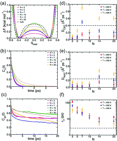 |
| | Fig. 22 (a) Free energy profiles of proton transfer in MIL-53(Cr) calculated as a function of the MS-EVB reaction coordinate qreac = c12 − c22. The results for bulk water are taken from ref. 78. (b) Continuous time correlation function, Cc(t). (c) Pseudocontinuous time correlation function, Cpc(t). All results for MIL-53(Cr) were obtained at T = 300 K as a function of the number of water molecules (N) adsorbed per unit cell. (d) Proton diffusion coefficient, DCEC, (e) water diffusion coefficient, DWAT, and (f) water orientational relaxation time, τ2, calculated MIL-53(Cr) as a function of both temperature and number of water molecules (N) adsorbed per unit cell. The dashed lines indicate the corresponding values calculated for bulk water at 300 K.78 Reproduced from ref. 79 with permission from American Chemical Society, Copyright 2012. | |
Borges et al. reported a joint experimental (QENS)/molecular dynamics (MD) simulation study of water-mediated proton transfer in UiO-66(Zr)–(CO2H)2.81 The structure of UiO-66(Zr)-(CO2H)2is constructed by Zr6O4(OH)4 cluster connected by six terepthalic acid functionalized with carboxylic acid.. This compound has two types of cages, tetrahedral (5.2 Å) and octahedral (7.0 Å) connected by a triangular window. It shows a high conductivity value (2.3 × 10⁻³ S cm−1) at RH 95% and 90 °C with a low activation energy of 0.17 eV. The result from the fitting of QENS at low and high Q indicated that there are two dynamic species. One is free protons diffusing to long distance and another is rotating water molecules. Proton diffusion happened predominantly from jumping between the solvated protons through local reorientational motion. The self-diffusion coefficients (Ds) of the proton and water are 3.5 × 10⁻⁹ m2 s−1 and 1.4 × 10⁻¹⁰ m2 s−1 at 373 K, respectively. Both exhibit lower values than those of bulk water (Ds(H2O) = 2.3 × 10⁻⁹ m2 s−1 and Ds(H+) = 9.4 × 10⁻⁹ m2 s−1 at 300 K)82,83 The computational approach of Ds for water is in good agreement with QENS data, whereas the simulated Ds(CEC), faster than that of H2O, was an underestimated QENS value (Fig. 23a). This observation means that proton transfer is dominated by the Grotthuss mechanism rather than the vehicle mechanism. Interestingly, MD trajectories proved that water molecules are positioned in a tetrahedral cage at 300 K having a strong interaction with the free –CO2H functional group. In addition the residence time of water molecules in the tetrahedral cage is quite long (ca. 3 ns) and few of them migrate to the octahedral cage exhibiting a stagnant H-bonding network in the tetrahedral cage. At high temperature, however, all cages are equally occupied by water molecules showing a longer H-bond network connected to two cages and a significantly decreased residence time (ca. 125 ps). The connection of cages through the longer H-bond network offers a path for proton jumping from one cage to another. Therefore, the high conductivity of UiO-66(Zr)–(CO2H)2 is attributed to the fast diffusivity over a long distance. The further in-depth exploration of MD simulation was carried out with dependence on the loading amounts of water molecules for the solvated proton structure, thermal dynamics and dynamics of hydrated protons in the 3D cage of UiO-66(Zr)–(CO2H)2.84 As the water loading increases, Ds(CEC) and Ds(H2O) present different trends (Fig. 24a). The former substantially increases with high loading of water corresponding to high conductivity. In contrast, Ds(H2O) has a maximum at the intermediated loading and decreases with high loading, where the guest diffusion suffers from a predominant steric hindrance effect. In addition, RDF shows a first peak around 2.5–2.6 Å which corresponds to the Zundel cation (2.5 Å). The small size (<3 A) of first coordination sphere for pivot-hydronium ion means the deficient solvation by water molecules. The average number of hydrogen bonds per water molecules (1.1, 1.5, 1.7, 2.0, and 2.15 for 20, 40, 50, 70, and 80H2O/(unit cell, uc) is lower than that of bulk water (3.6),85 which can be attributed to the confinement effect and hydrogen bonding with the –CO2H group. In addition, hydrogen bonding (HB) lifetimes (τHB) decrease and increase sequentially as loading amounts increase (low (93 ps), intermediate (23 ps), and high water loading (52 ps)). This can be explained by the strong trapping by –CO2H at low water loading, favorable interactions with more freedom at intermediate loading, and the static HB network induced by steric hindrance at high loading. The residence time of water in the cage at high loading is approximately 1.5 ns due to slow translation and rotation motion by the static HB network (Fig. 24b). The evaluation of excess proton migration from one cage to another cage shows a distinct number of cages crossing depending on the level of water loading. The high loading facilitates proton migration toward at least three tetrahedral cages and four octahedral cages. Therefore, high relative humidity is beneficial to create a conduction path between cages with high conductivity. Although MD simulation is beneficial for fundamental understanding of the conduction mechanism at the molecular level, the related studies are still scarce. Future endeavors for computational study toward the various MOF structures and conducting media are required.
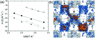 |
| | Fig. 23 (a) Arrhenius plot of Ds for protons (squares) and water molecules (circles) in the fully hydrated UiO-66(Zr)–(CO2H)2: QENS (open symbols) and aMS-EVB3-MD simulations (full symbols). (b) Illustration of simulation result for the water (blue)-mediated pathway with proton (orange) along the tetrahedral (A) and octahedral cages (B) of UiO-66(Zr)-(CO2H)2 at 450 K. Reproduced from ref. 81 with permission from Wiley-VCH, Copyright 2016. | |
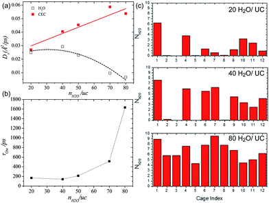 |
| | Fig. 24 (a) Self-diffusivities of water (empty symbols and dashed lines) and the center of excess charge (full symbols and solid lines) simulated at 400 K in UiO-66(Zr)–(CO2H)2 as a function of water loading defined as the number of water molecules (nH2O) per unit cell (uc). (b) Residence time of water molecules in the cages of UiO-66(Zr)–(CO2H)2 averaged over aMS-EVB3 trajectories obtained at 400 K as a function of water loading. (c) Simulated distribution of water in the tetrahedral (from 1 to 8) and octahedral (from 9 to 12) cages of UiO-66(Zr)–(CO2H)2 at 400 K. Reproduced from ref. 84 with permission from American Chemical Society, Copyright 2017. | |
4. Conclusions and prospects
A H-bonded degenerate system of a conducting medium through acid–base chemistry is an interesting platform to design efficient solid-state proton conductors. In particular, H2O and NH3 having an attractive conjugate acid–base system (H3O+–H2O, OH−–H2O, and NH4+–NH3 systems) are efficient conducting media because of their competent H-bonding ability. Recently, numerous reports have dealt with the proton conductivity of MOFs in various structural designs and strategies. In general, the proton conductivity of pristine MOFs is insignificant, whereas the incorporation of a proton conducting medium in a void space of MOFs considerably enhances the proton conductivity with the formation of a complete H-bonding network between the framework and the confined conducting medium. The major conducting medium of MOFs is water with additional acid molecules or functional groups for improved conductivity. In addition, NH3 as a conducting medium, which is either an alternative or a companion of water, has also attracted interest. The NH3 uptake in MOFs enhances the proton conduction properties and the coexistence with water facilitates protonation between the conducting media (NH3–H2O). However, the structural stability of MOFs in the presence of H2O and NH3 with a high proton conductivity is still challenging and indispensable for practical applications in energy carriers with high-performance proton conduction. In particular, the intuitive understanding of the conduction mechanism in NH3 mediated MOF proton conductors through the structural analysis is still scarce due to the structural stability problem.
To date, the investigation of proton conductivity in MOFs has focused on the discovery of a new proton-conducting pathway through the conducting medium; the scientific progress indicates a conductivity value comparable to that of Nafion. The accumulated experimental knowledge suggests that (1) a hydrophilic channel or (2) acid species contained in the pore and framework and (3) defect and disordered sites are the major factors for high proton conductivity in MOFs. Moreover, the proton donation by acidic species to the conducting medium expedites the development of a degenerate proton-conduction system with increased conductivity. For practical applications of proton-conductive MOFs to FCs, future endeavors for bulk protonic conductivity, stability of MOFs in the redox reaction process, and computational mechanism analysis are required. In conclusion, with consideration of all challenges, the development of potential MOF materials for high proton conductivity should be directed toward the use of inert and oxophilic metal species with a low pKa functional group of ligands. Furthermore, the expansion of materials to organic and inorganic species for composites is expected to achieve practical proton-conductive MOFs.
Conflicts of interest
There are no conflicts to declare.
Acknowledgements
This research was supported by the ACCEL program, Japan Science and Technology Agency (JST), JPMJAC1501.
References
- K. D. Kreuer, Chem. Mater., 1996, 8, 610–641 CrossRef CAS.
- G. Alberti, M. Casciola, U. Costantino and M. Leonardi, Solid State Ionics, 1984, 14, 289–295 CrossRef CAS.
- H. Iwahara, Solid State Ionics, 1996, 86–88 Search PubMed.
- E. Skou, P. Kauranen and J. Hentschel, Solid State Ionics, 1997, 97, 333–337 CrossRef CAS.
- K. A. Mauritz and R. B. Moore, Chem. Rev., 2004, 104, 4535–4586 CrossRef CAS PubMed.
- K. D. Kreuer, J. Membr. Sci., 2001, 185, 29–39 CrossRef CAS.
- A. I. Baranov, L. A. Shuvalov and N. M. Shchagina, JETP Lett., 1982, 36, 459 Search PubMed.
- S. M. Haile, D. A. Boysen, C. R. I. Chisholm and R. B. Merle, Nature, 2001, 410, 910–913 CrossRef CAS PubMed.
- T. Norby, M. Friesel and B. E. Mellander, Solid State Ionics, 1995, 77, 105–110 CrossRef CAS.
- X. Meng, H.-N. Wang, S.-Y. Song and H.-J. Zhang, Chem. Soc. Rev., 2017, 46, 464–480 RSC.
- N. Agmon, Chem. Phys. Lett., 1995, 244, 456–462 CrossRef CAS.
- K.-D. Kreuer, A. Rabenau and W. Weppner, Angew. Chem., Int. Ed., 1982, 3, 208–209 CrossRef.
- P. Ramaswamy, N. E. Wong and G. K. H. Shimizu, Chem. Soc. Rev., 2014, 43, 5913–5932 RSC.
- F. Hincal and P. Erkekoglu, FABAD J. Pharm. Sci., 2006, 31, 220–229 Search PubMed.
- Y. Brems, A. Lapkin and J. Baeyens, Int. J. Sustainable Eng., 2013, 6, 344–351 CrossRef.
- B. O. Bolaji and Z. Huan, Renewable Sustainable Energy Rev., 2013, 18, 49–54 CrossRef CAS.
- R. Lan and S. Tao, Front. Energy Res., 2014, 2, 1–4 Search PubMed.
-
United States Geological Survey, Nitrogen Statistics and Information, http://minerals.usgs.gov/minerals/pubs/commodity/nitrogen Search PubMed.
- W. C. Johnson and W. C. Fernelius, J. Chem. Educ., 1929, 6, 20–35 CrossRef CAS.
- C. J. Nyman, S.-C. Fung and H. W. Dodgen, J. Am. Chem. Soc., 1950, 72, 1033–1034 CrossRef CAS.
- A.-M. Goncalves, C. Mathieu, M. Herlem and A. Etcheberry, J. Electroanal. Chem., 1997, 477, 140–145 CrossRef.
- D. R. Clutter and T. J. Swift, J. Am. Chem. Soc., 1968, 90, 601–607 CrossRef CAS.
- V. F. Hnizda and C. A. Kraus, J. Am. Chem. Soc., 1949, 71, 1565–1575 CrossRef CAS.
- O. M. Yaghi, M. O'Keeffe, N. W. Ockwig, H. K. Chae, M. Eddaoudi and J. Kim, Nature, 2003, 423, 705–714 CrossRef CAS PubMed.
- S. Kitagawa, R. Kitaura and S. Noro, Angew. Chem., Int. Ed., 2004, 43, 2334–2375 CrossRef CAS PubMed.
- G. Férey and C. Serre, Chem. Soc. Rev., 2009, 38, 1380–1399 RSC.
- H.-C. Zhou, J. R. Long and O. M. Yaghi, Chem. Rev., 2012, 112, 673–674 CrossRef CAS PubMed.
- S. Kanda, K. Yamashita and K. Ohkawa, Bull. Chem. Soc. Jpn., 1979, 52, 3296–3301 CrossRef CAS.
- M. Sadakiyo, T. Yamada and H. Kitagawa, ChemPlusChem, 2016, 81, 691–701 CrossRef CAS.
- T. Yamada, K. Otsubo, R. Makiurac and H. Kitagawa, Chem. Soc. Rev., 2013, 42, 6655–6669 RSC.
- S. Horike, D. Umeyama and S. Kitagawa, Acc. Chem. Res., 2013, 46, 2376–2384 CrossRef CAS PubMed.
- M. Sadakiyo, T. Yamada and H. Kitagawa, J. Am. Chem. Soc., 2011, 133, 11050–11053 CrossRef CAS PubMed.
- M. Sadakiyo, T. Yamada and H. Kitagawa, J. Am. Chem. Soc., 2014, 136, 7701–7707 CrossRef CAS PubMed.
- Y.-S. Wei, X.-P. Hu, Z. Han, X.-Y. Dong, S.-Q. Zang and T. C. W. Mak, J. Am. Chem. Soc., 2017, 139, 3505–3512 CrossRef CAS PubMed.
- M. Inukai, S. Horike, T. Itakura, R. Shinozaki, N. Ogiwara, D. Umeyama, S. Nagarkar, Y. Nishiyama, M. Malon, A. Hayashi, T. Ohhara, R. Kiyanagi and S. Kitagawa, J. Am. Chem. Soc., 2016, 138, 8505–8511 CrossRef CAS PubMed.
- W. J. Phang, H. Jo, W. R. Lee, J. H. Song, K. Yoo, B. S. Kim and C. S. Hong, Angew. Chem., Int. Ed., 2015, 54, 5142–5146 CrossRef CAS PubMed.
- A. Shigematsu, T. Yamada and H. Kitagawa, J. Am. Chem. Soc., 2011, 133, 2034–2036 CrossRef CAS PubMed.
- J. M. Taylor, K. W. Dawson and G. K. H. Shimizu, J. Am. Chem. Soc., 2013, 135, 1193–1196 CrossRef CAS PubMed.
- P. Ramaswamy, R. Matsuda, W. Kosaka, G. Akiyama, H. J. Jeon and S. Kitagawa, Chem. Commun., 2014, 50, 1144–1146 RSC.
- S. Bureekaew, S. Horike, M. Higuchi, M. Mizuno, T. Kawamura, D. Tanaka, N. Yanai and S. Kitagawa, Nat. Mater., 2009, 8, 831–836 CrossRef CAS PubMed.
- D. Umeyama, S. Horike, M. Inukai, Y. Hijikata and S. Kitagawa, Angew. Chem., Int. Ed., 2011, 50, 11706–11709 CrossRef CAS PubMed.
- F.-M. Zhang, L.-Z. Dong, J.-S. Qin, W. Guan, J. Liu, S.-L. Li, M. Lu, Y.-Q. Lan, Z.-M. Su and H.-C. Zhou, J. Am. Chem. Soc., 2017, 139, 6183–6189 CrossRef CAS PubMed.
- V. G. Ponomareva, K. A. Kovalenko, A. P. Chupakhin, D. N. Dybtsev, E. S. Shutova and V. P. Fedin, J. Am. Chem. Soc., 2012, 134, 15640–15643 CrossRef CAS PubMed.
- K. D. Kreuer, S. J. Paddison, E. Spohr and M. Schuster, Chem. Rev., 2004, 104, 4637–4678 CrossRef CAS PubMed.
-
P. W. Atkins, Physical Chemistry, 6th edn, 1 Jan. 1998, p. 806 Search PubMed.
- R. C. T. Slade, A. Hardwick and P. G. Dickens, Solid State Ionics, 1983, 9–10, 1093–1098 CrossRef CAS.
- M. Sadakiyo, T. Yamada and H. Kitagawa, J. Am. Chem. Soc., 2009, 131, 9906–9907 CrossRef CAS PubMed.
- M. Sadakiyo, T. Yamada, K. Honda, H. Matsui and H. Kitagawa, J. Am. Chem. Soc., 2014, 136, 7701–7707 CrossRef CAS PubMed.
- M. Sadakiyo, H. Ōkawa, A. Shigematsu, M. Ohba, T. Yamada and H. Kitagawa, J. Am. Chem. Soc., 2012, 134, 5472–5475 CrossRef CAS PubMed.
- J. H. Cavka, S. Jakobsen, U. Olsbye, N. Guillou, C. Lamberti, S. Bordiga and K. P. Lillerud, J. Am. Chem. Soc., 2008, 130, 13850–13851 CrossRef PubMed.
- M. E. Tuckerman, D. Marx and M. Parrinello, Nature, 2002, 417, 925–929 CrossRef CAS PubMed.
- M. Sadakiyo, H. Kasai, K. Kato, M. Takata and M. Yamauchi, J. Am. Chem. Soc., 2014, 136, 1702–1705 CrossRef CAS PubMed.
- K. S. Park, Z. Ni, A. P. Cote, J. Y. Choi, R. Huang, F. J. Uribe-Romo, H. K. Chae, M. O'Keeffe and O. M. Yaghi, Proc. Natl. Acad. Sci. U. S. A., 2006, 103, 10186–10191 CrossRef CAS PubMed.
- N. Agmon, Chem. Phys. Lett., 2000, 319, 247–252 CrossRef CAS.
- S. S. Nagarkar, B. Anothumakkool, A. V. Desai, M. M. Shirolkar, S. Kurungot and S. K. Ghosh, Chem. Commun., 2016, 52, 8459–8462 RSC.
- Z. Li, Z. Zhang, Y. Ye, K. Cai, F. Du, H. Zeng, J. Tao, Q. Lin, Y. Zheng and S. Xiang, J. Mater. Chem. A, 2017, 5, 7816–7824 RSC.
- M. Krishnamurthy, J. A. de Gouw, L. N. Ding, V. M. Bierbaum and S. R. Leone, J. Chem. Phys., 1997, 106, 530–538 CrossRef CAS.
- M. Kandiah, M. H. Nilsen, S. Usseglio, S. Jakobsen, U. Olsbye, M. Tilset, C. Larabi, E. A. Quadrelli, F. Bonino and K. P. Lillerud, Chem. Mater., 2010, 22, 6632–6640 CrossRef CAS.
- N. C. Burtch, H. Jasuja and K. S. Walton, Chem. Rev., 2014, 114, 10575–10612 CrossRef CAS PubMed.
- D. Saha and S. Deng, J. Colloid Interface Sci., 2010, 348, 615–620 CrossRef CAS PubMed.
- G. W. Peterson, G. W. Wagner, A. Balboa, J. Mahle, T. Sewell and C. J. Karwacki, J. Phys. Chem. C, 2009, 113, 13906–13917 CrossRef CAS PubMed.
- T. Kajiwara, M. Higuchi, D. Watanabe, H. Higashimura, T. Yamada and H. Kitagawa, Chem.–Eur. J., 2014, 20, 15611–15617 CrossRef CAS PubMed.
- P. Küsgens, M. Rose, I. Senkovska, H. Fröde, A. Henschel, S. Siegle and S. Kaskel, Microporous Mesoporous Mater., 2009, 120, 325–330 CrossRef.
- K. A. Cychosz and A. J. Matzger, Langmuir, 2010, 26, 17198–17202 CrossRef CAS PubMed.
- C. Petit and T. J. Bandosz, Adv. Funct. Mater., 2010, 20, 111–118 CrossRef CAS.
- A. J. Rieth and M. Dinca, J. Am. Chem. Soc., 2018, 140, 3461–3466 CrossRef CAS PubMed.
- I. J. Kang, N. A. Khan, E. Haque and S. H. Jhung, Chem.–Eur. J., 2011, 17, 6437–6442 CrossRef CAS PubMed.
- S. Yang, X. Lin, A. J. Blake, G. S. Walker, P. Hubberstey, N. R. Champness and M. Schröder, Nat. Chem., 2009, 1, 487–493 CrossRef CAS PubMed.
- H. J. Park and M. P. Suh, Chem. Sci., 2013, 4, 685–690 RSC.
- A. Chakraborty, S. Bhattacharyya, A. Hazra, A. C. Ghosh and T. K. Maji, Chem. Commun., 2016, 52, 2831–2834 RSC.
- M. Sadakiyo, T. Yamada and H. Kitagawa, J. Am. Chem. Soc., 2014, 136, 13166–13169 CrossRef CAS PubMed.
- E. Pardo, C. Train, G. Gontard, K. Boubekeur, O. Fabelo, H. Liu, B. Dkhil, F. Lloret, K. Nakagawa, H. Tokoro, S. Ohkoshi and M. Verdaguer, J. Am. Chem. Soc., 2011, 133, 15328–15331 CrossRef CAS PubMed.
- M. Bazaga-García, R. M. P. Colodrero, M. Papadaki, P. Garczarek, J. Zoń, P. Olivera-Pastor, E. R. Losilla, L. León-Reina, M. A. G. Aranda, D. Choquesillo-Lazarte, K. D. Demadis and A. Cabeza, J. Am. Chem. Soc., 2014, 136, 5731–5739 CrossRef PubMed.
- X. Liang, B. Li, M. Wang, J. Wang, R. Liu and G. Li, ACS Appl. Mater. Interfaces, 2017, 9, 25082–25086 CrossRef CAS PubMed.
- R. L. Liu, L. L. Zhao, W. Dai, C. L. Yang and G. Li, Inorg. Chem., 2018, 57, 1474–1482 CrossRef CAS PubMed.
-
D.-W. Lim, H. Tsukada, A. Shigematsu, T. Yamada, K. Otsubo, A. E. Khudozhitkov, A. G. Stepanov, D. I. Kolokolov, M. Maesato and H. Kitagawa, DOI:10.26434/chemrxiv.7319273.v1.
- S. Miyatsu, M. Kofu, A. Nagoe, T. Yamada, M. Sadakiyo, T. Yamada, H. Kitagawa, M. Tyagi, V. G. Sakai and O. Yamamuro, Phys. Chem. Chem. Phys., 2014, 16, 17295–17304 RSC.
- F. Paesani, J. Phys. Chem. C, 2013, 117, 19508–19516 CrossRef CAS.
- K. Park, W. Lin and F. Paesani, J. Phys. Chem. B, 2012, 116, 343–352 CrossRef CAS PubMed.
- T. C. Berkelbach, H. S. Lee and M. E. Tuckerman, Phys. Rev. Lett., 2009, 103, 238302 CrossRef PubMed.
- D. D. Borges, S. Devautour-Vinot, H. Jobic, J. Ollivier, F. Nouar, R. Semino, T. Devic, C. Serre, F. Paesani and G. Maurin, Angew. Chem., Int. Ed., 2016, 55, 3919–3924 CrossRef CAS PubMed.
- K. Krynicki, C. D. Green and D. W. Sawyer, Faraday Discuss. Chem. Soc., 1978, 66, 199–208 RSC.
- N. K. Roberts and L. N. Helen, J. Chem. Soc., Faraday Trans., 1974, 70, 253–262 RSC.
- D. D. Borges, R. Semino, S. Devautour-Vinot, H. Jobic, F. Paesani and G. Maurin, Chem. Mater., 2017, 29, 1569–1576 CrossRef CAS.
- W. L. Jorgensen and C. Jenson, J. Comput. Chem., 1998, 19, 1179–1186 CrossRef CAS.
|
| This journal is © The Royal Society of Chemistry 2019 |
Click here to see how this site uses Cookies. View our privacy policy here.  Open Access Article
 a,
Masaaki
Sadakiyo
 b and
Hiroshi
Kitagawa
 *a
*a


![[thin space (1/6-em)]](https://www.rsc.org/images/entities/char_2009.gif) exp(−Ea/kBT)
exp(−Ea/kBT)
![[1 with combining macron]](https://www.rsc.org/images/entities/char_0031_0304.gif) ) because of a change in the orientation of H2adp molecules by tilting in the opposite direction, whereas the fundamental structure was the same as that of the trihydrate (Fig. 4). There is no structural difference between the dihydrate and anhydrate states except for the absence of water molecules. The H-bonding networks of these phases are shown in Fig. 4. The 2-D H-bonding network between ammonium ions, water molecules, and the carboxylic acid group in the trihydrate was changed into a localized H bond in the anhydrate state because of dehydration. In the dihydrate, there also exists a 2-D H-bonding network. However, the averaged distances of the H bonds in the dihydrate became longer than those in the trihydrate. Additionally, the number of H bonds also decreased. These different states showed different conductivities. The anhydrate exhibited an insulating character (∼10−12 S cm−1, 25 °C). The conductivity gradually increases with increasing RH (≤95%) to show a moderately high proton conductivity of around ∼10−4 S cm−1 in the dihydrate state. Finally, the trihydrate showed a superprotonic conductivity of around 10−2 S cm−1 at 98% RH. The proton conductivity in this system was consecutively controlled over the range from 10−12 to 10−2 S cm−1 because of the change in the H-bonding networks in the pores.48
) because of a change in the orientation of H2adp molecules by tilting in the opposite direction, whereas the fundamental structure was the same as that of the trihydrate (Fig. 4). There is no structural difference between the dihydrate and anhydrate states except for the absence of water molecules. The H-bonding networks of these phases are shown in Fig. 4. The 2-D H-bonding network between ammonium ions, water molecules, and the carboxylic acid group in the trihydrate was changed into a localized H bond in the anhydrate state because of dehydration. In the dihydrate, there also exists a 2-D H-bonding network. However, the averaged distances of the H bonds in the dihydrate became longer than those in the trihydrate. Additionally, the number of H bonds also decreased. These different states showed different conductivities. The anhydrate exhibited an insulating character (∼10−12 S cm−1, 25 °C). The conductivity gradually increases with increasing RH (≤95%) to show a moderately high proton conductivity of around ∼10−4 S cm−1 in the dihydrate state. Finally, the trihydrate showed a superprotonic conductivity of around 10−2 S cm−1 at 98% RH. The proton conductivity in this system was consecutively controlled over the range from 10−12 to 10−2 S cm−1 because of the change in the H-bonding networks in the pores.48


![[thin space (1/6-em)]](https://www.rsc.org/images/entities/char_2009.gif) exp(−ΔH/RT), where ΔS = 30.34 J mol−1 K−1 and ΔH = 3.4 kJ mol−1, coincides with the quantitative analysis of a relative population of two species through line-shape analysis. The T1 relaxation of the anisotropic signal shows a clear minimum (region a), whereas T1 of the isotropic signal exhibits flat-like behavior and a drastic increase in the high-temperature region (regions a′ and b′). This means that the mobile ND4+ has complex multiple motions in isotropic reorientation and an activation process mechanism change with the same geometrical motion. Considering the proton conduction mechanism, the local internal rotational motion of mobile ND4+ is responsible for the Grotthuss mechanism, resulting in the diffusion coefficient (D) evaluated from C3 axis rotation motion being 3.3 × 10⁻¹⁰ m2 s−1 with a 20 kJ mol−1 activation barrier. Furthermore, the high activation energy for proton conduction (0.46 eV) estimated from AC impedance measurements can account for the isotropic reorientation motion with random rotations, as well as the jump–diffusion process observed in region c′. The activation barrier of the related motion is 50 kJ mol−1, with a slow correlation time (τ = 3.6 × 10⁻⁵ s), which gives a low diffusion coefficient (1 × 10⁻¹⁵ m2 s−1) at 300 K. Although this is a lower diffusion coefficient value than that of the hopping mechanism, the value is acceptable considering the observed conductivity. The solid-state NMR measurement strongly supports the proton conduction mechanism predicted from the crystallographic analysis.
exp(−ΔH/RT), where ΔS = 30.34 J mol−1 K−1 and ΔH = 3.4 kJ mol−1, coincides with the quantitative analysis of a relative population of two species through line-shape analysis. The T1 relaxation of the anisotropic signal shows a clear minimum (region a), whereas T1 of the isotropic signal exhibits flat-like behavior and a drastic increase in the high-temperature region (regions a′ and b′). This means that the mobile ND4+ has complex multiple motions in isotropic reorientation and an activation process mechanism change with the same geometrical motion. Considering the proton conduction mechanism, the local internal rotational motion of mobile ND4+ is responsible for the Grotthuss mechanism, resulting in the diffusion coefficient (D) evaluated from C3 axis rotation motion being 3.3 × 10⁻¹⁰ m2 s−1 with a 20 kJ mol−1 activation barrier. Furthermore, the high activation energy for proton conduction (0.46 eV) estimated from AC impedance measurements can account for the isotropic reorientation motion with random rotations, as well as the jump–diffusion process observed in region c′. The activation barrier of the related motion is 50 kJ mol−1, with a slow correlation time (τ = 3.6 × 10⁻⁵ s), which gives a low diffusion coefficient (1 × 10⁻¹⁵ m2 s−1) at 300 K. Although this is a lower diffusion coefficient value than that of the hopping mechanism, the value is acceptable considering the observed conductivity. The solid-state NMR measurement strongly supports the proton conduction mechanism predicted from the crystallographic analysis.
![[thin space (1/6-em)]](https://www.rsc.org/images/entities/char_2009.gif) ln(qreac), qreac = c12 − c22 (c12 and c22 being the probabilities of the two EVB states) (Fig. 22a). The central point (qreac = 0.0) means that the excess proton has symmetric hydrogen bonding with donor and acceptor water molecules. As shown in Fig. 22a, the free energy barrier is lower than that of bulk water excluding N = 10 where MIL-53 undergoes a pore transition from narrow to a large pore. Moreover, the increased temperature reduces the barrier height. Overall, the relatively low free energy barrier clearly reflects that the confined environment facilitates more proton conduction than bulk water. The lifetimes, τpc, evaluated from the fitting of the long-time decay of Cpc(t) are short with tens of picoseconds for N = 3, 5, 10, which are longer than that of bulk water (τpc = 1.7 ps).80 It is implied that long distance proton transfer through the confined water in MIL-53 is suppressed compared to that in the bulk system. This result is coincident with the diffusion coefficient (Fig. 22d and e). As a result, the confined water-mediated proton conduction in MIL-53 shows a low free energy barrier for proton transfer with slow proton diffusion suggesting a slow rearrangement of hydrogen bonding in the pore.
ln(qreac), qreac = c12 − c22 (c12 and c22 being the probabilities of the two EVB states) (Fig. 22a). The central point (qreac = 0.0) means that the excess proton has symmetric hydrogen bonding with donor and acceptor water molecules. As shown in Fig. 22a, the free energy barrier is lower than that of bulk water excluding N = 10 where MIL-53 undergoes a pore transition from narrow to a large pore. Moreover, the increased temperature reduces the barrier height. Overall, the relatively low free energy barrier clearly reflects that the confined environment facilitates more proton conduction than bulk water. The lifetimes, τpc, evaluated from the fitting of the long-time decay of Cpc(t) are short with tens of picoseconds for N = 3, 5, 10, which are longer than that of bulk water (τpc = 1.7 ps).80 It is implied that long distance proton transfer through the confined water in MIL-53 is suppressed compared to that in the bulk system. This result is coincident with the diffusion coefficient (Fig. 22d and e). As a result, the confined water-mediated proton conduction in MIL-53 shows a low free energy barrier for proton transfer with slow proton diffusion suggesting a slow rearrangement of hydrogen bonding in the pore.


