 Open Access Article
One metal is enough: a nickel complex reduces nitrate anions to nitrogen gas†
Jinseong
Gwak
 a,
Seihwan
Ahn
 ab,
Mu-Hyun
Baik
 *ba and
Yunho
Lee
 *a
*a
aDepartment of Chemistry, Korea Advanced Institute of Science and Technology (KAIST), Daejeon 34141, South Korea. E-mail: yunholee@kaist.ac.kr; mbaik2805@kaist.ac.kr
bCenter for Catalytic Hydrocarbon Functionalizations, Institute for Basic Science (IBS), Daejeon 34141, South Korea
First published on 9th April 2019
Abstract
A stepwise reduction sequence from nitrate to dinitrogen gas at a single nickel center was discovered. A PNP nickel scaffold (PNP− = N[2-PiPr2-4-Me-C6H3]2) emerged as a universal platform for the deoxygenation of NOx substrates. In these reactions carbon monoxide acts as the oxygen acceptor and forms CO2 to provide the necessary chemical driving force. Whereas the first two oxygens are removed from the Ni-nitrate and Ni-nitrite complexes with CO, the deoxygenation of NO requires a disproportionation reaction with another NO molecule to form NO2 and N2O. The final deoxygenation of nitrous oxide is accomplished by the Ni–NO complex and generates N2 and Ni–NO2 in a relatively slow, but clean reaction. This sequence of reactions is the first example of the complete denitrification of nitrate at a single metal-site and suggests a new paradigm of connecting CO and NOx as an effective reaction pair for NOx removal.
Introduction
The production of hazardous nitrogen oxides (NOx) from human industrial activity is a serious environmental concern.1 While both nitrogen dioxide (NO2) and nitric oxide (NO) are hazardous pollutants found in automobile exhaust,2 nitrate (NO3−) has also recently been scrutinized as a water pollutant. Nitrate is utilized in large quantities in the agricultural industry as fertilizers and is leaked into surface and underground water reservoirs, where it has a significant impact on aquatic life. Being stable and highly soluble, this pollutant cannot be removed easily from water supplies.3 The most desirable solution for the removal of nitrate is to chemically reduce it to more benign products such as nitrogen and oxygen or water. In nature, enzymatic denitrification requires a multi-step process to reduce nitrate to N2 in the biological nitrogen cycle, as summarized in Fig. 1.4 Although these enzymatic reactions occur under mild conditions, four different metalloenzymes are needed to reduce nitrate in the sequence NO3− → NO2− → NO → N2O → N2, highlighting the difficulty of carrying out the 5-electron reduction from nitrate to nitrogen.Industrially, most efforts on NOx reduction are focused on NO and NO2 to meet stringent governmental emission requirements for the automobile industry. The technical solution currently implemented for these pollutants relies on thermolysis by fuel reburning or selective catalytic reduction with ammonia added as a reaction partner.5 The current consecration catalyst mainly utilizes noble metals such as Pt and Rh embedded on a ceramic support but the energy cost and inefficiencies of these technologies remain problematic.6
To overcome these inefficiencies, new chemical strategies for NOx reduction must be developed. In 1962, Chatt suggested an unconventional NOx conversion strategy,7 where the addition of CO to metal-nitrate and -nitrite species produces metal-nitrosyl and CO2, representing a potential technology for NOx reduction. Despite the attractiveness of this route, synthetic systems that operate through such a reaction sequence have not been realized.8 Inspired by this work, we developed a complete reaction cycle that sequentially removes oxygen from NO3− to finally afford N2 gas, using a nickel pincer complex.
Results and discussion
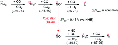
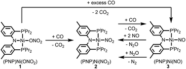
Fig. 2 summarizes the free energy change of the nitrate reduction series estimated using high-level quantum chemical calculations at the ccCA-CC(2,3) level of theory.9 Not surprisingly, the sequential reductions of nitrate to NO2− and NO− using CO are downhill with a Gibbs free energy of −56.7 and −15.6 kcal mol−1, respectively. The removal of the last oxygen atom from NO− to formally afford the nitrogen mono anion is understandably not favorable and uphill by 35.7 kcal mol−1. Thus, a more realistic plan for removing the oxygen atom from NO− is to first remove an electron, i.e. oxidize it to form the neutral NO, which our calculations estimate to be associated with a reasonable oxidation potential of ∼0.5 V vs. NHE, then engage two NO and one CO molecules to form nitrous oxide (N2O) and release CO2. Previously, the disproportionation of three equivalents of NO to afford NO2 and N2O was observed10 and several first-row metal complexes have been shown to facilitate such disproportionation.11 In good agreement with these observations, the analogous reaction of 2NO + CO → N2O + CO2 is calculated to be highly exergonic with a Gibbs free energy of −84.6 kcal mol−1. The final reduction of N2O to form N2 is even more exergonic at −88.0 kcal mol−1 and has also been observed previously.12 Although the reaction pathway described above is plausible conceptually, carrying out the full reaction series from NO3− to N2 at a single metal-center proved exceedingly difficult and is not known to date. Given that nature has chosen to use different metalloenzymes for each of the reductions, one may question whether the complete denitrification at a single reactive site is fundamentally possible. Herein, we report the first example of a full denitrification sequence promoted by a single metal complex. Utilizing a tridentate PNP ligand (PNP− = N[2-PiPr2-4-Me-C6H3]2), a square-planar Ni(II)-complex was prepared13 with an empty coordination site that we envisioned may constitute a versatile binding site for various NOx substrates, Scheme 1.Nickel nitrate to nitrosyl
A nickel nitrate species (PNP)Ni(ONO2) (1) was prepared by an anion metathesis reaction of (PNP)Ni(OTf),14 (OTf− = trifluoromethanesulfonate) with sodium nitrate and isolated as a green powder in good yield (31P NMR: δ 35.79 ppm, 84.5%). A 15N substituted nickel nitrate complex, 1-O15NO2 exhibits a singlet 15N NMR signal at −12.42 ppm and the nitrate based vibration can be recognized by isotope shift (νNO2: 1482, 1280 cm−1, Δ(15NO2) = 40, 23 cm−1, νNO: 1000 cm−1, Δ(15NO) = 17 cm−1). The solid-state structure of 1 (Fig. 3a) shows that one of the oxygen atoms of a NO3− moiety is coordinated to a square planar nickel(II) center with the bond length of 1.897(2) Å. Interestingly, 1 exhibits a remarkable reactivity towards CO and oxygen atom transfer reactions can be observed starting from the nickel nitrate to the corresponding nickel nitrosyl species. The addition of CO (1 atm) to a green C6D6 solution of 1 resulted in a rapid and clean conversion in less than 1 hour at room temperature to the nitrosyl complex (PNP)Ni(NO) (3), which was followed by 31P NMR spectroscopy (31P NMR: δ 52.57 ppm, 87.0%). A 15N labeled nickel nitrosyl species, 3-15NO was also prepared by the same synthetic method using 1-O15NO2 revealing a triplet 15N NMR signal at 241.44 ppm (J = 14.64 Hz) and a doublet 31P NMR signal (J = 14.58 Hz). The expected side product CO2 was detected by gas chromatography (Fig. S17†). The solid-state structure of 3 (Fig. 3c) reveals a four coordinate nickel species possessing a single nitrosyl ligand. 3 is a {Ni(NO)}10 complex in the Enemark–Feltham notation, as there are 10 electrons in the metal d and NO π* orbitals. If the deoxygenation of nitrate to the nitric oxide proceeds in a stepwise manner traversing the nitrite stage, we expect to observe either the Ni-nitrito or the Ni-nitro intermediate. 31P NMR spectroscopy studies indicated that a single new intermediate displaying a singlet at 42.29 ppm was formed. In order to confirm the identity of this species, (PNP)NiCl was reacted with sodium nitrite in THF and the formation of the diamagnetic nickel-nitrite complex, (PNP)Ni(NO2) (2) was observed, which was isolated as a purple powder in good yield (82.1%). 2 exhibits the identical 31P NMR signal as the intermediate found in the reaction mixture. A 15N labeled nickel nitrite complex, 2-15NO2 exhibits a triplet 15N NMR signal at 89.89 ppm (J = 7.93 Hz) and a doublet 31P NMR signal (J = 8.10 Hz). IR data of 2 exhibit an asymmetric stretching vibration of a nitro moiety at 1361 cm−1 (Δ(15NO2) = 19 cm−1) and a symmetric stretching vibration at 1334 cm−1 (Δ(15NO2) = 25 cm−1) which is consistent with other nickel(II) nitro complexes.15 Solid-state XRD data shows that 2 is a nickel(II)-nitro complex (Fig. 3b) with a Ni–N distance of 1.860(4) Å as shown in Table 1. These observations strongly support the assignment that the Ni-nitro complex is formed as an intermediate and reacts readily to afford the Ni-nitrosyl complex under the given conditions liberating another equivalent of CO2. To further support this conclusion, we reacted the independently prepared sample of 2 with CO and observed the formation of 3 and CO2, as expected (Fig. S16†). Finally, the addition of one equivalent of CO to 1 also gave 2 cleanly. | ||
| Fig. 3 Displacement ellipsoid (50%) representation of (a) (PNP)Ni(ONO2) (1), (b) (PNP)Ni(NO2) (2) and (c) (PNP)Ni(NO) (3). Hydrogen atoms and molecules of cocrystallization are omitted for clarity. | ||
| Ni–N1 (Å) | Ni–P1, 2 (Å) | Ni–La (Å) | N1–Ni–La (°) | P1–Ni–P2 (°) | τ 4 | |
|---|---|---|---|---|---|---|
a L = O(1) for 1, N(2) for 2 and 3.  α, β = the two largest angles in the four-coordinate species. α, β = the two largest angles in the four-coordinate species.
|
||||||
| (PNP)Ni(ONO2) (1) | 1.887(3) | 2.215(1), 2.220(1) | 1.897(2) | 175.4(1) | 169.3(4) | 0.11 |
| (PNP)Ni(NO2) (2) | 1.907(4) | 2.192(1), 2.193(1) | 1.860(4) | 176.1(2) | 170.5(2) | 0.10 |
| (PNP)Ni(NO) (3) | 1.999(4) | 2.223(1), 2.244(1) | 1.694(4) | 148.5(2) | 142.5(5) | 0.49 |
| 1.997(4) | 2.248(1), 2.218(1) | 1.698(4) | 148.7(2) | 142.7(5) | 0.49 | |
Mechanism
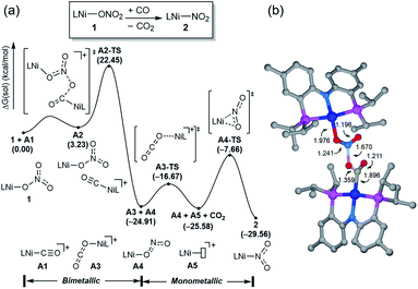
Having observed the initial reactivity of the nickel nitrate complex 1, its ability to engage in an oxygen atom transfer reaction with CO and the mechanism of the reaction were studied using density functional theory (DFT) calculations. And these calculations reveal that although nickel acts as the single reactive site for the removal of all three oxygen atoms, the mechanisms of removing each of them are completely and fundamentally different. This finding is perhaps not surprising given how chemically different each of the oxygen atoms are in the nitrate, nitrite and nitric oxide moieties.Our calculations indicate that removing the first oxygen atom from nitrate is most problematic. Exhaustive efforts did not result in any reaction pathway with a reasonable barrier that would enable a direct attack of the CO on the Ni-nitrato complex to give CO2. The lowest barrier we were able to locate for such a simple process was 37.6 kcal mol−1, which is not consistent with a reaction that occurs readily at room temperature, as depicted in Fig. S42.† This finding is counterintuitive at first sight, since the driving force for the removal of the first oxygen via CO2 formation is greatest at nearly −57 kcal mol−1, as mentioned above. This finding highlights that the core problem of deoxygenating nitrate is a kinetic and not necessarily a thermodynamic challenge. The only possible reaction mechanism associated with a reasonable barrier involves the reaction of the Ni-nitrato complex with a Ni-carbonyl species that may be formed by a nickel center reacting with a CO as described in Fig. 4a.16 The transition state A2-TS for this bimetallic mechanism was located at 22.5 kcal mol−1 and the structure of the transition state is shown in Fig. 4b. The transition state is relatively late with respect to the O2N–O bond breaking and O–CO formation at calculated bond lengths of 1.67 and 1.36 Å, respectively, i.e. at the transition state the O2N–O bond is mostly broken and the O–CO has been formed mostly. Because this step involves the transfer of an oxygen atom, carbon dioxide and the nitrite anion are produced in nickel-bound forms initially, but CO2 is quickly released traversing transition state A3-TS with a negligible barrier of 8.2 kcal mol−1. The nickel-nitrito complex rearranges readily to the nickel-nitro intermediate 2viaA4-TS. These calculations show that free CO is not oxophilic enough to extract an oxygen atom directly from nitrate and requires a Ni(II)-center to enhance its oxophilicity.
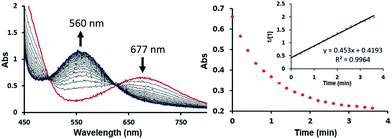
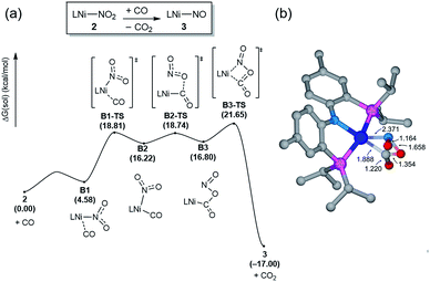
The bimetallic mechanism described above was not anticipated and, thus, a new set of experiments was conducted to test this hypothesis. Kinetic experiments using UV-vis spectroscopy were carried out to determine the reaction order as a function of nickel concentration as shown in Fig. 5. If the proposed mechanism is correct, the rate of this reaction step should show a second order dependence on the concentration of the Ni-complex. Upon addition of CO at 273 K to a THF solution of 1 (2.80 mM) shows a complete conversion within 5 min to an violet solution of 2 exhibiting an UV-vis absorption decrease at 677 nm and increase at 560 nm. The kinetic plots clearly show a pseudo-second-order decay monitored by the consumption of 1. During the measurements in 0.2 min intervals, an isosbestic point appears, indicating that no observable intermediate or side product is formed. These experiments lend strong support to the proposed bimetallic mechanism. Fig. 6 summarizes the proposed mechanism for the deoxygenation of the nitro moiety. Unlike what was described above, CO does not need a second nickel center. Instead, it coordinates directly to the (PNP)Ni(NO2) complex 2 to give intermediate B1, which is slightly higher in energy than 2. Next, CO migrates from the axial to the equatorial position viaB1-TS and forms intermediate B2, which is located at 16.2 kcal mol−1. Intermediate 3 is generated by the migration of the nitro group to CO viaB2-TS and extracts the oxygen atom from the nitro group via the transition state B3-TS with a barrier of 21.6 kcal mol−1. In addition, at the transition state B3-TS, the ON–O bond is almost broken and the O–CO has been formed which has calculated bond lengths of 1.66 and 1.35 Å, respectively, as shown in Fig. 6b. Whereas this mechanism is pertinent, we considered plausible alternatives, such as the bimetallic pathway. Our calculations show that the bimetallic pathway is associated with a higher barrier of ∼39 kcal mol−1 and maybe therefore not operative (Fig. S44†). Thus, our calculations suggest a very different, much simpler mechanism for this second deoxygenation, which is possible because the nitrogen is directly bound to the nickel center and the N–O bond can be influenced more easily by the metal. The difficulty described above for the deoxygenation of nitrate where the nitrogen is not directly bound to the metal contrasts this effect and highlights that for effective reactivity, the metal must be engaged in close contact.
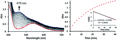
To test this mechanistic proposal, we sought to determine the reaction order for this step by monitoring the reaction progress using UV-vis spectroscopy, as we did for the first step, as described in Fig. 7. Since only a single metal-center is involved, the reaction rate should show a first order dependence on the concentration of the Ni-complex. Upon addition of CO to a THF solution of 2 (1.13 mM) at room temperature complete conversion was observed within 1 hour to a brown solution of 3, indicated by a characteristic UV-vis absorption increase at 479 nm. The rate law is pseudo-first-order determined by monitoring the decay of 2. These findings suggest strongly that the rate determining step of the second deoxygenation involves only a single nickel complex, as is proposed by the DFT-calculations. The calculated barrier of 21.7 kcal mol−1 is also compatible with a moderately fast reaction at room temperature.
Oxidation state of Ni in 3
Because nitric oxide is well-known to be redox non-innocent, determining the exact oxidation state of the metal nitrosyl species is difficult. In particular, late transition metal nitrosyl complexes often feature complicated electronic structures that introduce significant ambiguity in assigning the formal oxidation state of the metal. In principle, there are three possible resonance structures, as indicated below.There is no ambiguity about 2 containing a Ni(II) center and, thus, we may leave the metal-oxidation state unchanged at +2, which assigns the NO ligand to be formally anionic in this Ni(II)-d8 16-electron complex, where the nickel-nitrosyl functionality is expected to be significantly bent in structure. Alternatively, the nitrosyl may reduce the nickel-center to Ni(I) and become a neutral ligand, in which case a notable radical character should reside on the nitrosyl moiety. The NO ligand is also expected to show a non-linear arrangement in this case. Finally, one may write down a Ni(0) configuration in principle, in which the nitrosyl is a cationic isolobe of a carbonyl ligand in linear arrangement. This last case is highly unlikely, as a Ni(0)-d10 species is not compatible with the PNP framework. Thus, the main question is whether the nickel center in 3 is in +2 or +1 oxidation state. This question is highly relevant for the deoxygenation mechanism. As pointed out above, the deoxygenation series requires the oxidative transition into the neutral ligand domain to remove the oxygen atom from NO. If the nitrosyl is already in the formally neutral state, the deoxygenation protocol can proceed, but if the (PNP)Ni(II) fragment is not able to support the oxidation, we must induce the oxidation externally.
To shed light on this question, we first inspected the IR spectrum to determine if the nitrosyl vibration can offer some clue about the oxidation state of nickel. The nitrosyl vibration of 3 appears at 1646 cm−1 (Δ(15NO) = 30 cm−1),17 which does not allow for unambiguously assigning it to a NO− or NO0 moiety because this value lies in the middle of the classical metal nitrosyl vibration range. Thus, the nitrosyl vibrational spectrum cannot be used as diagnostic tool for the electronic structure in solution. Structurally, a significant distortion away from a square planar geometry about the nickel center (τ4 = 0.49) and the non-linear binding of NO with the Ni–N–O bond angle of 145° in the crystal structure is observed, as expected for either the Ni(II) or Ni(I) case. For a Ni(II)-center interacting with a formally anionic NO, we expect to observe a more acute binding angle. Thus, the crystal structure suggests that complex 3 may contain a Ni(I)-center. The metrical parameters with dNi1–N2 = 1.694(4) Å and dN2–O1 = 1.174(6) Å and the aforementioned vibrational frequency compare well with a previous reported four-coordinate nickel nitrosyl complex, (PNP*)Ni(NO) (PNP* = (tBu2PCH2SiMe2)2N) by Caulton and coworkers (νNO = 1654 cm−1, dNi–N = 1.692(4) Å, dN–O = 1.185(5) Å, ∠Ni–N–O = 149.3(4)°).18 The nickel in this complex was assigned to be a Ni(I)-center.18
The electronic structure of 3 can be further examined by DFT-calculations. We obtained several optimized structures and probed for different spin states that are plausible. First, the structural data from calculation showed excellent agreement with experimental metrical parameters (dNi–N = 1.701 Å, dN–O = 1.191 Å, ∠Ni–N–O = 140.8°) when the closed-shell singlet is chosen, as described in Table 2. There are four occupied frontier orbitals that are primarily 3d in character, and the HOMO−1 (Fig. S40†) is heavily dominated by the nitrosyl π* fragment orbital, which is responsible for the binding seen for the Ni–NO moiety. The LUMO and LUMO+1 (Fig. S40†) of 3 are composed of the two orthogonal π* orbitals of the NO ligand. This is the electronic signature of a complex where a Ni(II)-center engages a formally anionic NO− ligand.
| Open-shell singlet | Closed-shell singlet | Triplet | Experimental | |
|---|---|---|---|---|
| Ni–P1/2 (Å) | 2.280/2.333 | 2.253/2.315 | 2.265/2.311 | 2.244(1)/2.223(1) |
| Ni–N1 (Å) | 2.025 | 2.008 | 1.961 | 1.999(4) |
| Ni–N2 (Å) | 1.740 | 1.701 | 1.894 | 1.694(4) |
| N2–O1 (Å) | 1.187 | 1.191 | 1.222 | 1.174(6) |
| P1–Ni1–P2 (°) | 136.7 | 137.4 | 166.5 | 142.5(5) |
| N1–Ni1–N2 (°) | 151.9 | 153.6 | 177.6 | 148.5(2) |
| Ni1–N2–O1 (Å) | 142.7 | 140.8 | 128.7 | 145.4(4) |
| ν NO (cm−1) | 1675.8 | 1662.6 | 1498.6 | 1646 |
| ΔG (kcal mol−1) | 0.00 | 1.99 | 6.79 |
The alternative to the closed-shell singlet state, which enforces a Ni(II) configuration is an open-shell resonance form, which gives access to an unconventional Ni(I)-d9 center with a radicaloid NO functionality, where the unpaired electrons on the metal and the ligand adopt opposite spins to each other. The calculated unpaired spin densities are Ni: 0.57, N: −0.43, O: −0.31 with the minus sign denoting β-spin densities. Energetically, this electronic structure is the lowest in energy with the closed-shell singlet being only 2 kcal mol−1 higher in energy. The triplet state yields a small spin density on nickel and a large spin density on the nitrosyl moiety, namely Ni: 0.29, N: 0.98, O: 0.62 and shows a remarkably different geometry compared to the singlet states. The nickel-center is much more planar and the Ni–NO shows a much more acute angle (dNi1–N2 = 1.894 Å, dN–O = 1.222 Å, ∠Ni–N–O = 128.7°) and is 6.8 kcal mol−1 higher in energy than the open-shell singlet state. Taken together, these experimental and computational data suggest that the nickel center in 3 is best characterized as Ni(I) and the NO ligand is formally a neutral ligand, as was planned originally for the deoxygenation series.
Disproportionation
To complete the denitrification sequence, the disproportionation of NO was envisioned, because the simple minded deoxygenation of NO to give the nitride anion is unwise, as explained above. Previously, various metal complexes including Co, Mn, Fe or Cu have been reported to be capable of promoting this reaction.11 Especially, the nickel nitrosyl [(bipy)(Me2phen)Ni(NO)][PF6] reported by the Hayton group mediates NO disproportionation in the presence of gaseous nitric oxide to give N2O via a cis-hyponitrite species.11j In addition, a significant amount of spin density at the nitrosyl N atom brings NO coupling. The Warren group reported a {Ni(NO)}11 species, [iPr2NNF6]Ni(μ-η2:η2-NO)K(18-crown-6)(THF) reveals a facile coupling with NO to give the cis-hyponitrite which releases N2O upon protonation.19 After some experimentation we found that this strategy can be implemented by letting intermediate 3 react with exogenous nitric oxide. Treating the brown solution of 3 with two equivalents of NO (1 atm) in benzene at room temperature resulted in a slow color change to a violet solution over 2 hours. The resulting solution contains 2 recognized again by its 31P NMR signature at 42.3 ppm and we were able to isolate it as a purple solid (87.8%). The gaseous product N2O was detected by gas chromatography in 54% yield from the headspace analysis (Fig. S18†). As a control experiment, the same reaction was conducted in the absence of 3 and, as expected, no nitrous oxide was detected. The uncatalyzed disproportionation of NO in gas phase (3NO → N2O + NO2) is known to be kinetically challenged and exceedingly slow.10 Consequently, we were unable to detect any N2O in the NO gas supply, but we still wished to confirm that the disproportionation really takes place at the Ni-center and, thus, we utilized tritylthionitrite as an organic NO source. Treatment of 3 with 2 equivalents of tritylthionitrite in benzene results in the formation of 2 in 91.0% and N2O in 56% yield, respectively (Fig. S19†). Therefore, the reaction of 3 with two molecules of NO produces Ni(II)–NO2 and N2O, as conceptually imagined.The DFT-calculated reaction energy profile and the mechanism for this step is shown in Fig. 8. First, the exogenous nitric oxide radical approaches intermediate 3, directly attacking the nitrogen and readily forms a N–N bond to give the intermediate C2 which is located at −2.7 kcal mol−1. Next, the dioxohydrazine fragment rearranges from the N-bound to an O-bound isomer C3 traversing the transition state C2-TS with a barrier of 23.6 kcal mol−1. Not surprisingly, dioxohydrazine is not tightly bound and many conformational isomers exist in equilibrium. Among them, intermediate C4 in which one oxygen and one distal nitrogen atoms are engaged by the nickel center to form a four-membered metallacycle, is important for the reaction. A second equivalent of exogenous nitric oxide radical is consumed and it attacks the nickel-bound O of the dioxohydrazine to form N2O via an SN2-like transition state C5-TS, which is the most difficult step in this reaction sequence and is associated with a reasonable barrier of 25.8 kcal mol−1 measured from C2. Release of N2O gives the nickel-nitrito complex A4, which can quickly rearrange viaA4-TS with a barrier of 17.9 kcal mol−1 to form the nickel-nitro complex 2. In addition, we investigated a five-membered metallacycle pathway as illustrated in Fig. S46.† The computed results indicate that the five-membered metallacycle formation with a slightly higher barrier of 29.1 kcal mol−1 needs relatively harsher conditions. Thus, we surmised that the four-membered metallacycle pathway is the lowest energy pathway.
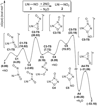 | ||
| Fig. 8 Proposed reaction pathways (B3LYP-D3/B2//B3LYP-D3/B1) of the N2O generation and the catalyst regeneration step. | ||
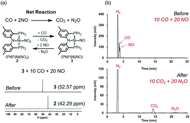
The regeneration of 2 after release of nitrous oxide suggests that a catalytic cycle can be designed where NO will be reduced while CO is oxidized to produce CO2 and N2O as described in Fig. 9a. Given that both gases are often encountered together for example in the automobile exhaust gas,1,5 this finding is particularly interesting and suggests a potential alternative to selective catalytic reduction process that is currently used in the automobile industry.5 Efforts towards exploiting this feature and developing such a technology for removing NO is currently underway in our laboratory. To confirm that a catalytic cycle can be established with the current system, 10 equivalents of CO and 20 equivalents of NO were added to the solution of 3 in benzene at room temperature. Headspace analysis of gas products confirmed that all gaseous reagents were converted to N2O and CO2 within 140 minutes at room temperature with at least 80% of the Ni-catalyst remaining intact as shown in Fig. 9a and b. In the final step, the oxygen atom must be removed from the N2O reactant to afford N2. Interestingly, complex 3, which contains the nickel-nitrosyl fragment, was found to be reactive to nitrous oxide. Exposure of a benzene solution of 3 at 60 °C to an N2O atmosphere yielded 2 in 36 hours with minor impurities. Most likely, the nitrous oxide attacks the Ni–NO fragment to transfer the last oxygen to NO forming Ni–NO2 (2) and N2.12 Compared to the other steps of the reaction, this last step is slow. Nonetheless, we were able to detect the gas product N2 in the headspace by gas chromatography in 41% yield (Fig. S21†).
Conclusions
In conclusion, we present for the first time a stepwise transformation of NO3− all the way to N2 by a single reaction site, a (PNP)Ni-complex. The driving force for these remarkable sequence of transformations is provided by CO, which serves as the ultimate recipient of the oxygen atoms to form CO2. We demonstrate therefore that although nature has chosen to use different metalloenzymes for each of the deoxygenation steps, it is in principle possible to design a single transition metal catalyst that can moderate the entire reaction. But we also demonstrate that the internal mechanism of each deoxygenation steps are vastly different. The first step requires a bimetallic mechanism, where CO must be activated by a second nickel-site to accept the oxygen atom, the second deoxygenation is the least problematic step with the Ni-nitro functionality readily affording the Ni-nitrosyl complex and CO2. To remove the last oxygen from NO, we must add NO to initially form the dioxohydrazine, which then liberates nitrous oxide, N2O. This part of the reaction is catalytic and offers potential solutions for removing hazardous NO and CO gas at the same time. The nickel-nitrosyl complex is surprisingly versatile, as it can also perform the final deoxygenation, whereby the NO acts as oxygen acceptor and produces NO2 and the final product N2.Conflicts of interest
There are no conflicts to declare.Acknowledgements
Y. L. and J. G. acknowledge the support from C1 Gas Refinery Program (NRF 2015M3D3A1A01064880) and the KAIST High Risk High Return Project (HRHRP). M.-H. B. and S. A. acknowledge support from the Institute for Basic Science (IBS-R10-A1) in Korea.Notes and references
- (a) D.-H. Lee, B. Mondal and K. D. Karlin, Activation of Small Molecules: Organometallic and Bioinorganic Perspectives, Wiley-VCH, New York, 2006 Search PubMed; (b) A. R. Ravishankara, Chem. Rev., 2003, 103, 4505 CrossRef CAS PubMed; (c) P. Granger and V. I. Parvulescu, Chem. Rev., 2011, 111, 3155 CrossRef CAS PubMed; (d) Q. Schiermeier, Nature, 2015 DOI:10.1038/nature.2015.18426.
- (a) M. V. Twigg, Appl. Catal., B, 2007, 70, 2 CrossRef CAS; (b) G. Whiteman and H. Hoster, Nature, 2015, 527, 38 CrossRef CAS PubMed.
- (a) W. L. Zhang, Z. X. Tian, N. Zhang and X. Q. Li, Agric., Ecosyst. Environ., 1996, 59, 223 CrossRef CAS; (b) K. R. Burow, B. T. Nolan, M. G. Rupert and N. M. Dubrovsky, Environ. Sci. Technol., 2010, 44, 4988 CrossRef CAS PubMed; (c) C. L. Ford, Y. J. Park, E. M. Matson, Z. Gordon and A. R. Fout, Science, 2016, 354, 741 CrossRef CAS PubMed.
- (a) I. M. Wasser, S. de Vries, P. Moënne-Loccoz, I. Schröder and K. D. Karlin, Chem. Rev., 2002, 102, 1201 CrossRef CAS PubMed; (b) B. A. Averill, Chem. Rev., 1996, 96, 2951 CrossRef CAS PubMed; (c) K. Inatomi and L. I. Hochstein, Curr. Microbiol., 1996, 32, 72 CrossRef CAS; (d) A. C. Merkle and N. Lehnert, Dalton Trans., 2012, 41, 3355 RSC; (e) S. R. Pauleta, S. Dell'Acqua and I. Moura, Coord. Chem. Rev., 2013, 257, 332 CrossRef CAS; (f) L. B. Maia and J. J. G. Moura, Chem. Rev., 2014, 114, 5273 CrossRef CAS PubMed.
- I. A. Reşitoğlu, K. Altinişik and A. Keskin, Clean Technol. Environ. Policy, 2015, 17, 15 CrossRef.
- (a) V. Rosca, M. Duca, M. T. de Groot and M. T. M. Koper, Chem. Rev., 2009, 109, 2209 CrossRef CAS PubMed; (b) S. Roy, M. S. Hegde and G. Madras, Appl. Energy, 2009, 86, 2283 CrossRef CAS.
- G. Booth and J. Chatt, J. Chem. Soc., 1962, 2099 RSC.
- (a) O. A. Heperuma and R. D. Feltham, J. Am. Chem. Soc., 1976, 98, 6039 CrossRef CAS; (b) R. D. Feltham and J. C. Kriege, J. Am. Chem. Soc., 1979, 101, 5064 CrossRef CAS; (c) J. Kriege-Simondsen, G. Elbaze, M. Dartiguenave, R. D. Feltham and Y. Dartiguenave, Inorg. Chem., 1982, 21, 230 CrossRef CAS; (d) J. Kriege-Simondsen, T. D. Bailey and R. D. Feltham, Inorg. Chem., 1983, 22, 3318 CrossRef CAS.
- (a) C. Peterson, D. A. Penchoff and A. K. Wilson, Annu. Rep. Comput. Chem., 2016, 12, 3 Search PubMed; (b) In these conceptual energy calculations, the NO− anion is assumed to be a triplet, which is the lowest energy state in gas phase.
- (a) G. B. Richter-Addo and P. Legzdins, Metal Nitrosyls, Oxford University Press, New York, 1992 Search PubMed; (b) P. P. Paul and K. D. Karlin, J. Am. Chem. Soc., 1991, 113, 6331 CrossRef CAS; (c) S. Mahapatra, J. A. Halfen and W. B. Tolman, J. Chem. Soc., Chem. Commun., 1994, 1625 RSC; (d) T. W. Hayton, P. Legzdins and W. B. Sharp, Chem. Rev., 2002, 102, 935 CrossRef CAS PubMed.
- (a) D. Gwost and K. G. Caulton, Inorg. Chem., 1974, 13, 414 CrossRef CAS; (b) C. E. Ruggiero, S. M. Carrier and W. B. Tolman, Angew. Chem., Int. Ed., 1994, 33, 895 CrossRef; (c) J. L. Schneider, S. M. Carrier, C. E. Ruggiero, V. G. Young and W. B. Tolman, J. Am. Chem. Soc., 1998, 120, 11408 CrossRef CAS; (d) K. J. Franz and S. J. Lippard, J. Am. Chem. Soc., 1998, 120, 9034 CrossRef CAS; (e) K. J. Franz and S. J. Lippard, J. Am. Chem. Soc., 1999, 121, 10504 CrossRef CAS; (f) G. G. Martirosyan, A. S. Azizyan, T. S. Kurtikyan and P. C. Ford, Chem. Commun., 2004, 1488 RSC; (g) F. Roncaroli, R. van Eldik and J. A. Olabe, Inorg. Chem., 2005, 44, 2781 CrossRef CAS PubMed; (h) G. G. Martirosyan, A. S. Azizyan, T. S. Kurtikyan and P. C. Ford, Inorg. Chem., 2006, 45, 4079 CrossRef CAS PubMed; (i) A. M. Wright, G. Wu and T. W. Hayton, J. Am. Chem. Soc., 2012, 134, 9930 CrossRef CAS PubMed; (j) A. M. Wright, H. T. Zaman, G. Wu and T. W. Hayton, Inorg. Chem., 2014, 53, 3108 CrossRef CAS PubMed; (k) A. M. Wright and T. W. Hayton, Inorg. Chem., 2015, 54, 9330 CrossRef CAS PubMed.
- (a) V. N. Parmon, G. I. Panov, A. Uriarte and A. S. Noskov, Catal. Today, 2005, 100, 115 CrossRef CAS; (b) W. B. Tolman, Angew. Chem., Int. Ed., 2010, 49, 1018 CrossRef CAS PubMed; (c) K. Severin, Chem. Soc. Rev., 2015, 44, 6375 RSC; (d) V. N. Cavaliere, M. G. Crestani, B. Pinter, M. Pink, C.-H. Chen, M.-H. Baik and D. J. Mindiola, J. Am. Chem. Soc., 2011, 133, 10700 CrossRef CAS PubMed; (e) B. Horn, C. Limberg, C. Herwig, M. Feist and S. Mebs, Chem. Commun., 2012, 48, 8243 RSC; (f) A. G. Tskhovrebov, E. Solari, R. Scopelliti and K. Severin, Organometallics, 2012, 31, 7235 CrossRef CAS.
- (a) C. Yoo, J. Kim and Y. Lee, Organometallics, 2013, 32, 7195 CrossRef CAS; (b) C. Yoo, S. Oh, J. Kim and Y. Lee, Chem. Sci., 2014, 5, 3853 RSC.
- L. Fan and O. V. Ozerov, Chem. Commun., 2005, 35, 4450 RSC.
- (a) J. Kriege-Simondsen and R. D. Feltham, Inorg. Chim. Acta, 1983, 71, 185 CrossRef CAS; (b) S. Supriya and S. K. Das, Inorg. Chem. Commun., 2009, 12, 364 CrossRef; (c) J. R. Zimmerman, B. W. Smucker, R. P. Dain, M. J. V. Stipdonk and D. M. Eichhorn, Inorg. Chim. Acta, 2011, 373, 54 CrossRef CAS PubMed.
- As an alternative pathway, the reaction of [(PNP)Ni(CO)][BF4] with sodium nitrate was conducted. No reaction occurs at 60 °C for 12 h in THF and elevated temperature shows the formation of unknown species instead of any nickel nitrite or nitrosyl species.
- In solid-state IR data, two peaks are seen due to the two different structures identified in XRD studies. These peaks collapse to a single feature in the solution IR spectrum.
- (a) B. C. Fullmer, M. Pink, H. Fan, X. Yang, M.-H. Baik and K. G. Caulton, Inorg. Chem., 2008, 47, 3888 CrossRef CAS PubMed; (b) Both Ni–NO complexes reveal the Ni–N bond length of ∼1.69 Å, which is clearly shorter than the Ni(II)–L bond length of 1.86–1.90 Å for 1 and 2. This is due to the significant back-bonding and geometrical distortion of a Ni(I) complex.
- S. Kundu, P. N. Phu, P. Ghosh, S. A. Kozimor, J. A. Bertke, S. C. E. Stieber and T. H. Warren, J. Am. Chem. Soc., 2019, 141, 1415 CrossRef CAS PubMed.
Footnote |
| † Electronic supplementary information (ESI) available. CCDC 1867435, 1867437 and 1867438. For ESI and crystallographic data in CIF or other electronic format see DOI: 10.1039/c9sc00717b |
| This journal is © The Royal Society of Chemistry 2019 |


