3D-Printed highly stretchable conducting polymer electrodes for flexible supercapacitors†
Jiayu
Yang
a,
Qinghe
Cao
a,
Xiaowan
Tang
a,
Junjie
Du
a,
Tao
Yu
 *a,
Xi
Xu
 a,
Dongming
Cai
b,
Cao
Guan
 *a and
Wei
Huang
a
aFrontiers Science Center for Flexible Electronics, Institute of Flexible Electronics, Northwestern Polytechnical University, Xi'an 710072, P. R. China. E-mail: iamtyu@nwpu.edu.cn; iamcguan@nwpu.edu.cn
bCollege of Chemical Engineering, Hubei University, Wuhan 430062, P. R. China
First published on 7th May 2021
Abstract
Recent advances in the development of wearable, implantable, and bio-integrated electronic devices have increased the demand for stretchable and flexible energy storage devices that can deliver high degrees of mechanical deformability. However, the fabrication of fully flexible electronics with both satisfactory electrochemical performance and mechanical stretchability remains a significant technological hurdle. In this work, by synergistically combining theoretical structural design and 3D printing, additive-free free-standing stretchable electrodes with different negative Poisson's ratio (NPR) structures have been developed based on a poly(3,4-ethylenedioxythiophene):polystyrene sulfonate (PEDOT:PSS) ink. Through tensile tests and finite element analyses (FEA), the stretchable electrode with a well-designed arc-shaped NPR structure can effectively reduce the peak strain, resulting in excellent flexibility (up to 180°) and stretchability (maximum elongation 150%). Through further integration of carbon nanotubes (CNTs), the 3D printed hybrid polymer/CNT electrode exhibits enhanced electrochemical performance with a high area capacitance of 990 mF cm−2. The as-fabricated quasi-solid-state symmetric supercapacitor not only achieves a satisfactory energy density and maintains excellent capacitance retention of 74.7% after 14![[thin space (1/6-em)]](https://www.rsc.org/images/entities/char_2009.gif) 000 cycles, but also shows promising mechanical properties by maintaining stable power output even when being extremely deformed. The strategy proposed here offers promising opportunities in developing novel deformable electrodes for integrated wearable energy storage devices in various applications.
000 cycles, but also shows promising mechanical properties by maintaining stable power output even when being extremely deformed. The strategy proposed here offers promising opportunities in developing novel deformable electrodes for integrated wearable energy storage devices in various applications.
Introduction
Over the past few decades, wearable systems that can sense and respond to environmental stimuli have been causing a paradigm shift in consumer electronics such as wearable sensors, artificial organs, prosthetics, smart electronic skin, human-activity monitoring, and continuous health monitoring.1–3 The development of smart wearable systems has ignited tremendous interest in the realization of next-generation stretchable electronic devices with an elastic mechanical response and high performance. To ensure sustainable operation of such advanced electronic systems on non-planar and dynamic surfaces such as the human body, the corresponding energy storage devices must output stable and continuous electrical energy even when deformed into arbitrary complex shapes, such as compressing,4,5 twisting,6 folding,7 and stretching.8,9 As one of the most mainstream personalized electronics, supercapacitors with intriguing characteristics of not only high-power density, and fast rates of charge–discharge but also long cycling lifetimes, are regarded as promising smart and portable electronics.10–12A key challenge for designing an independent flexible and stretchable supercapacitor is developing stretchable electrodes that can maintain structural integrity during repeated severe deformations that is beyond what is possible with rigid conventional devices.13–18 Currently, several types of conventional strategies have been proposed to achieve stretchable electrodes. Among them, the most common strategy is to deposit active materials on stretchable elastic substrates such as polyurethane (PU), polydimethylsiloxane (PDMS), and thermoplastic copolyester (Ecoflex). However, these conventional stretchable electrodes are limited by the deformability of the substrate during the stretching or deformation process.19,20 Moreover, most of these substrates are subject to the drawbacks of low capacitance and high resistance, which may result in poor electrochemical performance.21 Another approach to achieve stretchable electrodes is applying structural engineering techniques to reduce the stresses placed on the material, e.g. modifying the geometric structure of non-stretchable materials into helical, serpentine, sponge, wavy and net configurations.22 Similarly, fabrics with specific patterns prepared by fiber-shaped electrodes can also adapt to the strain in the stretching deformation process.23 The application of structural engineering technology usually relies on the structural design of electrodes.24,25 The specific geometric structure can convert the linear strain received by the electrode into bending or buckling strain, providing good opportunities to construct stretchable electrodes based on rigid materials.26
Electrodes with a NPR structure have demonstrated significantly improved stretchability and flexibility.27,28 Under vertical tension, conventional materials tend to expand in the vertical direction and contract in the lateral direction, while auxetic materials with a NPR structure will expand in all directions when pulled in only one direction.29,30 When a material with a well-designed NPR cell topology is subjected to compressive or tensile loads, the expansion structure caused by the rotation of the elastic cell reduces the bulk modulus, thus prohibits the generation of volume expansion and effectively alleviates the fracture of the material.31 However, electrodes with complex NPR structures can be hardly achieved through conventional fabrication techniques, such as coating, screen printing, photolithography, and inkjet printing.32–35 In this regard, ink-based 3D printing, a powerful additive manufacturing technology, has shown unparalleled advantages in the rational structure design of materials and devices with accuracy and efficiency even in micro and macro scales.36–39 A series of extrusion-based 3D printing supercapacitor electrode strategies have been proposed; however, such electrodes are limited to conventional structures including the microlattice, mesh and interdigitation structures, which limits their application for wearable and skin-attached electronic devices.40
Herein, we propose an economical and efficient strategy to prepare a free-standing stretchable electrode with multidimensional property tunability and a NPR structure, where a high-concentration, viscoelastic, and additive-free high-performance conductive polymer PEDOT:PSS ink is prepared and direct ink writing (DIW) technology and structural patterning design are utilized. With the deformable pattern design, the arc-shaped microstructure is introduced into the conventional NPR structure, which overcomes the limitations of non-tunable mechanical behavior and broadens the narrow strain ranges of traditional supercapacitor electrodes. The diversity of microstructures provides a wider range of effective strain and stress relief for the electrodes, which shows a great degree of freedom in the design of stretchable electrodes. FEA results confirm that the well-designed arc-shaped microstructure provides a uniform stress area and reduces the peak strain in the electrode that leads to a “super” performance including excellent flexibility, and extreme stretchability (maximum elongation 150%). In addition to mechanical flexibility, the all-polymer electrode also delivers a favorable area capacitance. To further improve the performance, CNTs were added to the ink formulation and the optimized hybrid polymer/CNT electrode achieves a high area capacitance of 990 mF cm−2. A quasi-solid-state symmetric supercapacitor is further assembled and exhibits a high energy density of 0.065 mW h cm−2 and maintains excellent capacitance after 14![[thin space (1/6-em)]](https://www.rsc.org/images/entities/char_2009.gif) 000 cycles.
000 cycles.
Experimental section
Preparation of inks
In order to formulate high-concentration printable conductive polymer inks, it is necessary to immerse a commercially available PEDOT:PSS aqueous solution in liquid N2, and then freeze-dry for 36 h to form PEDOT:PSS nanofibrils. The detailed preparation process of conductive polymer printable ink was as follows: 0.5 g of PEDOT:PSS nanofibrils were dispersed in 8 mL deionized water or a binary solvent mixture (DMSO![[thin space (1/6-em)]](https://www.rsc.org/images/entities/char_2009.gif) :
:![[thin space (1/6-em)]](https://www.rsc.org/images/entities/char_2009.gif) DI = 15
DI = 15![[thin space (1/6-em)]](https://www.rsc.org/images/entities/char_2009.gif) :
:![[thin space (1/6-em)]](https://www.rsc.org/images/entities/char_2009.gif) 85 v/v) followed by thorough mixing and homogenization with constant stirring, and then a sonication bath with the temperature maintained at 10 °C was used to further mix the inks for 2 h. PEDOT:PSS nanofibrils dispersed in a binary solvent is represented as PEDOT:PSS-D. The preparation of PEDOT:PSS/CNT ink was similar to the above process. Typically, 20 mL of modified CNT paste (Chengdu Organic Chemicals Co., Ltd.) was mixed with 0.5 g PEDOT:PSS nanofibrils to obtain a homogeneous printable ink. The mass ratio of PEDOT:PSS/CNT in the inks was 5
85 v/v) followed by thorough mixing and homogenization with constant stirring, and then a sonication bath with the temperature maintained at 10 °C was used to further mix the inks for 2 h. PEDOT:PSS nanofibrils dispersed in a binary solvent is represented as PEDOT:PSS-D. The preparation of PEDOT:PSS/CNT ink was similar to the above process. Typically, 20 mL of modified CNT paste (Chengdu Organic Chemicals Co., Ltd.) was mixed with 0.5 g PEDOT:PSS nanofibrils to obtain a homogeneous printable ink. The mass ratio of PEDOT:PSS/CNT in the inks was 5![[thin space (1/6-em)]](https://www.rsc.org/images/entities/char_2009.gif) :
:![[thin space (1/6-em)]](https://www.rsc.org/images/entities/char_2009.gif) 4.
4.
3D printing of suitably patterned electrodes
The printable conductive polymer-based ink was transferred into a 3 mL disposable plastic syringe which was attached by a Luer lock to a stainless-steel nozzle whose inner diameter is 100 μm. Different three-dimensional NPR patterns were realized by a 3D robotic dispenser system (Fisnar F4200N). The prepared ink was then extruded using a high precision pressure controller (Fisnar DSP501N) which provides a constant extruding pressure of 30 psi to extrude filaments smoothly on a glass substrate under ambient conditions, and the nozzle's moving speed was kept at 2 mm s−1 for all the NPR patterns. Printing paths of different NPR patterns were generated by CAD drawings, which converts the model information into G-code to regulate the x–y–z motion of the pneumatic syringe. In order to avoid structural deformation or cracking due to evaporation of water, soon after printing, the 3D-printed conducting polymer architectures were immersed in liquid nitrogen, followed by freeze drying for 10 h in a vacuum to yield the electrodes. PEDOT:PSS-D and PEDOT:PSS/CNT electrodes were constructed under the same preparation conditions.Assembly of the 3D-printed quasi-solid-state supercapacitor
The quasi-solid-state symmetric supercapacitor was fabricated using 3D-printed PEDOT:PSS or 3D-printed PEDOT:PSS/CNT electrodes with PVA-H2SO4 gel as the electrolyte. The polymer gel electrolyte was obtained by slow addition of 2 g PVA (Mw = 67![[thin space (1/6-em)]](https://www.rsc.org/images/entities/char_2009.gif) 000) to 20 mL of deionized water with vigorous magnetic stirring at 90 °C until the solution became clear. Then, it was mixed with 2 g H2SO4 and stirred for another 1 h. Subsequently, the gel electrolyte was cast onto the surfaces of the 3D-printed electrodes. After evaporation of excess water under ambient conditions, the as-prepared electrodes were allowed to be assembled face-to-face. The assembled quasi-solid-state symmetric supercapacitor was then packed and further tested.
000) to 20 mL of deionized water with vigorous magnetic stirring at 90 °C until the solution became clear. Then, it was mixed with 2 g H2SO4 and stirred for another 1 h. Subsequently, the gel electrolyte was cast onto the surfaces of the 3D-printed electrodes. After evaporation of excess water under ambient conditions, the as-prepared electrodes were allowed to be assembled face-to-face. The assembled quasi-solid-state symmetric supercapacitor was then packed and further tested.
FEA calculations
The uniaxial tensile behavior of the printed electrodes with different geometric shapes was analysed by FEA simulation with the ABAQUS/Standard. The elastic properties of PEDOT:PSS were derived from the experiment. The results demonstrated that the Poisson's ratio of PEDOT:PSS is 0.38, and the elastic modulus is 750 MPa. Four different NPR structures were investigated, each of which was arranged periodically. The thickness of the electrode is 0.1 mm in cross-section, and the width of the filaments forming the multi-structured electrode is 0.4 mm. To obtain a precise direction of the tensile behavior of the four patterns, the left boundary of each pattern was fixed in the initial step with four freedom degrees remaining except for the x and z direction. Then the right boundary was stretched in the x direction and fixed in the z direction to prevent intense out-of-plane deformations. The patterns were meshed by C3D20H elements based on the medial axis algorithm and the mesh size was 0.1 mm. The calculations were implemented by nonlinear general static analysis.Materials characterization experiments
The morphology of the prepared 3D-printed electrodes was studied by transmission electron microscopy (TEM, FEI Talos F200) and scanning electron microscopy (SEM, Zeiss, 5.0–20.0 kV) with an EDX detector. The structural properties of the prepared electrodes were studied by X-ray diffraction (XRD, Bruker D8 advance), X-ray photoelectron spectroscopy (XPS, Kratos, Axis Supra) and Raman spectroscopy (WITec Alpha300R, 532 nm). All rheological properties of formulated ink were measured at 25 °C by using a stress-controlled Rheometer (Thermo Fisher MARS60) with a 20 mm-flat plate geometry and a gap of 500 μm. The mechanical properties tests were conducted by using a flexible device test system (FlexTest-S-P2).Electrochemical measurements
The resistance of the stretchable electrodes with different structures was measured by using a Keithley 2450 digital multimeter. All the electrochemical characterization studies including cyclic voltammetry (CV), galvanostatic charge–discharge (GCD) measurements, and electrochemical impedance spectroscopy (EIS) which performed with the frequency range from 100 kHz to 0.01 Hz were assessed utilizing an electrochemical workstation (CHI 760E, CH Instruments Inc., Shanghai). For three-electrode system tests, directly using the 3D-printed electrode in 1 M H2SO4 electrolyte solution as the working electrode, a Ag/AgCl electrode and Pt foil served as the reference electrode and the counter electrode, respectively. For two-electrode system tests, the two same 3D-printed electrodes served as the cathode and anode, respectively. The cycle stability performance was studied using a LANHE battery testing system.The areal capacitance (CA) and specific capacitance (C) of the 3D-printed electrodes and the devices were calculated based on the GCD curves according to the following equations:
 | (1) |
 | (2) |
 | (3) |
 | (4) |
Results and discussion
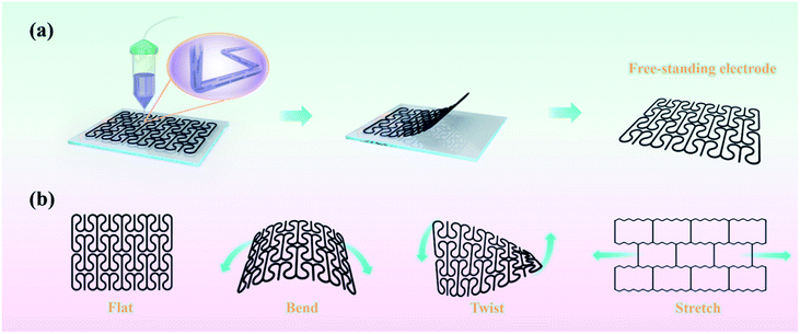
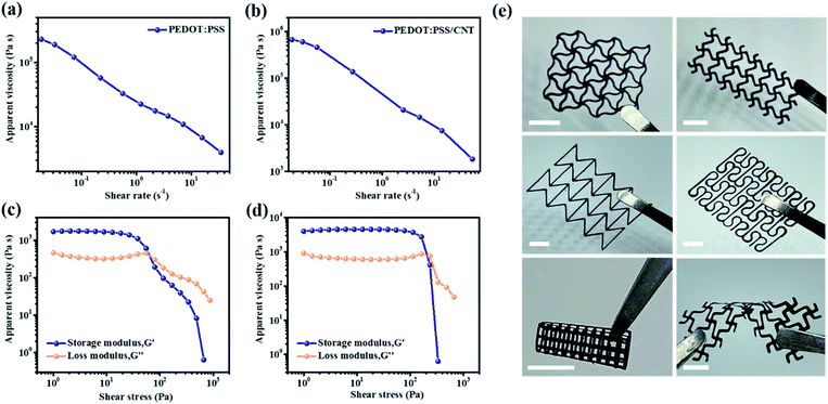
Fig. 1a schematically demonstrates the fabrication process of stretchable electrodes with arc-shaped NPR patterns via 3D printing technology. By re-dispersing PEDOT:PSS nanofibrils with deionized water, the dispersion of PEDOT:PSS nanofibrils gradually transforms from a low-viscosity liquid to a printable conductive polymer-based ink as the concentration of PEDOT:PSS nanofibers increases (Fig. S2a–d, ESI†). The homogeneous conductive polymer-based ink then extruded through a 100 μm diameter moveable nozzle to construct multilayer, program-controlled 3D NPR structures (Video S1, ESI†). Although the filament will expand within a controllable range when passing through the nozzle, the PEDOT:PSS filament still exhibited accurate and stable 3D characteristics due to the excellent rheological properties of the conductive polymer-based ink. In addition, the PEDOT:PSS/CNT composite ink was formulated by simply adding PEDOT:PSS nanofibrils into a CNT suspension. After freeze-drying, the printed 3D microstructure can be easily lifted to become a freestanding electrode. This eliminates the necessity of employing noble metals or other conductive materials as current collectors. Fig. 1b schematically depicts the excellent deformability and flexibility of the electrode with well-designed arc-shaped NPR pattern.The rheological behavior of the ink has a significant influence on the 3D printing process. Under high shear stress, the printable ink for DIW should exhibit a relatively low elastic shear modulus so that it can pass through the nozzle smoothly. In addition, the static elastic modulus of the as-prepared ink is supposed to be large enough to allow the filament to maintain its shape on the substrate without collapsing due to self-weight and surface tension. For this purpose, conducting polymer-based inks with suitable rheological properties were designed for extrusion-based 3D printing. As shown in Fig. 2a, b and S3a (ESI†), the three inks show the same shear thinning characteristics, indicating that they are non-Newtonian fluids which is essential for a printable ink to flow continuously. At a shear rate of 1 s−1, each ink shows an apparent viscosity ranging from 104 to 105 Pa s, which enables excellent printability of the conducting polymer-based inks to form complex 3D architectures. To further evaluate the viscous properties of conductive polymer-based inks, oscillatory measurements were conducted to measure the storage (G′) and loss modulus (G′′), as shown in Fig. 2c, d and S3b.† The storage modulus plateaus of both PEDOT:PSS an PEDOT:PSS/CNT are located between 103 and 104 Pa, and is approximately one order of magnitude higher than the loss modulus. The predominant elastic behavior (G′ > G′′) indicates a stiffer ink with structural robustness. After the crossover point between G′ and G′′, with the increase of shear stress, G′ decreases more drastically, which is helpful for smooth extrusion of ink. Meanwhile, the high yield stress and plateau moduli indicate better stacking of the material in the vertical direction. To demonstrate the printability of the ink, electrodes with different thicknesses and various complicated patterns (Fig. S4, ESI†) were prepared by continuous layer-by-layer extrusion of conductive polymer-based inks without any additives. The precise and stable 3D features shown by the filaments on the substrate verified the suitability of the ink for the high productivity and accuracy 3D printing process. Due to the low shrinkage of freeze-drying and the ability to preserve the internal integrity and external shape of the structure, the wet 3D structures were subsequently freeze-dried to obtain freestanding electrodes with well-defined shapes (Fig. 2e).
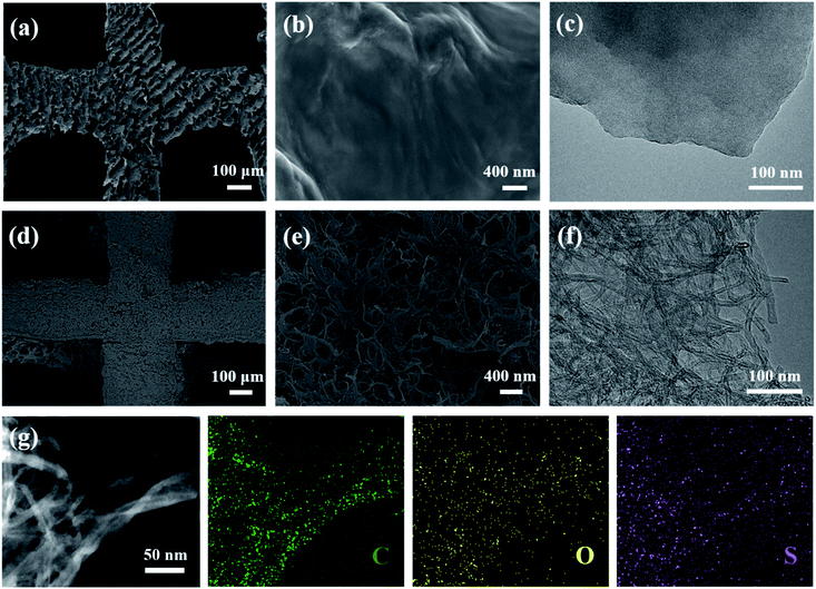
The morphology and detailed microstructure of the 3D-printed PEDOT:PSS and PEDOT:PSS/CNT electrodes were investigated using SEM and TEM, as shown in Fig. 3a–g. From Fig. 3a, d and S5a, b (ESI†), one can see that the multilayer PEDOT:PSS, PEDOT:PSS-D and PEDOT:PSS/CNT electrodes are composed of continuous and uniform filaments, which stacked on top of each other with a diameter of about 200–300 μm. As observed from the SEM images at high magnification (Fig. 3b, e and S5c†), numerous CNTs are densely and uniformly incorporated in the conductive polymer framework, and the CNTs are also interconnected with each other, which is favourable for fast electron transfer. In addition, plenty of nanogaps and microchannels are formed between the entangled CNTs, which is beneficial for electrolyte penetration and facilitates fast ion diffusion. The nanostructures of the 3D-printed PEDOT:PSS and PEDOT:PSS/CNT electrodes were further characterized by TEM. Compared to Fig. 3c and S5d,† it is evident that the framework of PEDOT:PSS is completely filled with CNTs (Fig. 3f), which is consistent with the results of SEM. It can be observed that the CNTs were highly aligned with each other along the extrusion direction due to the shear flow conditions in the 3D printing process (Fig. S5f†), which was different from the random distribution of CNTs in the conventional preparation method. The arrangement and compact structure of CNTs can efficiently improve the mechanical properties of composite electrodes. The EDS mapping result further confirms the uniform distribution of CNTs in the PEDOT:PSS framework (Fig. 3g and S5e†).
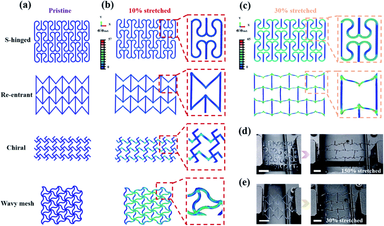
Different network topologies are proved to be the vital factor influencing the stretchability of the electrodes. In this work, four NPR structures are studied, which are S-hinged, re-entrant, chiral, and wavy mesh. Both the stress and strain behavior of the electrode was studied by combining the uniaxial tensile with FEA. First, the uniaxial tensile deformation behavior of the varied configurations was simulated using FEA. Fig. 4b and S6 (ESI†) show the deformed configurations and stress distribution of electrodes with four different topologies (as shown in Fig. 4a) under 10% tensile simulation along the x direction. The probability of fracture of these four patterns decreases with the reduction of the red zone. Obviously, the electrode with a wavy mesh structure exhibits the highest maximum stress in contrast to the lowest maximum stress in S-hinged geometry electrodes. In order to further explore the ability of different NPR structures to disperse stress, a higher stretch rate was simulated in electrodes with re-entrant and S-hinged structures. Fig. 4c shows a 30% stretch simulation of the two structures in the x direction. By comparing the two electrodes with different structures, it can be found that for the electrode with the re-entrant structure, the stress is concentrated at the corner of the whole structure. When the strain reaches 30%, the local stress at the corner of the joint reached the critical stress, that is, the electrode was likely to break in the maximum stress locations which were concentrated at the corner. In contrast, the S-hinged structure minimizes the stress concentration by distributing stress over the entire length of the hinge, and the maximum local stress can be significantly reduced in the same tensile state. This delocalization of stress enables the structure with promising elastic macroscopic strain. The axial tensile test data of the printed electrodes with different NPR structures are consistent with the simulation results, where the ultimate tensile rates of the electrodes with S-hinged, re-entrant, chiral and wavy mesh structures are 150%, 30%, 18% and 11.5%, respectively (Fig. 4d, e and S7†). The values of the electrode with the S-hinged structure are better than those of many previously reported stretchable electrodes (Fig. S8†). To investigate the stability of the electrode with the S-hinged structure in response to repeated stretching, a fatigue test was carried out. The experimental results showed that the electrode was able to recover almost all its initial strain after 100 repetitive stretchings (Video 2, ESI†).
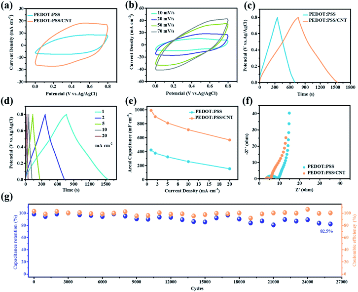
The electrochemical characterization of the 3D-printed PEDOT:PSS and PEDOT:PSS/CNT electrodes was further investigated (Fig. 5). The CV curve of the 3D-printed PEDOT:PSS/CNT electrode exhibits a better rectangular shape and larger integral area than the 3D-printed PEDOT:PSS electrode (Fig. 5a), reflecting improved capacitance after the addition of the CNT. As shown in Fig. 5b and S9a,† even at a high scan rate of 70 mV s−1, the CV curve of the 3D-printed electrode maintains a quasi-rectangular shape, which proves the high rate properties of the electrode. Fig. 5c, d and S9b† show almost linear charge–discharge curves of the electrodes, and the resulting areal capacitances are shown in Fig. 5e. Notably, at the same current density of 1 mA cm−2, the PEDOT:PSS/CNT electrode shows a high areal capacitance of 990 mF cm−2, which is 2.33 times that for PEDOT:PSS. The Nyquist plots in Fig. 5f show that the PEDOT:PSS/CNT electrode has a shorter intercept and a steeper slope, indicating that the addition of the CNT significantly increases the conductivity of the electrode. As shown in Fig. 5g, the PEDOT:PSS/CNT electrode maintains an excellent capacitance retention of 82.5% and nearly 100% coulombic efficiency after 25![[thin space (1/6-em)]](https://www.rsc.org/images/entities/char_2009.gif) 000 cycles. The electrical stability as a function of cycling was tested by measuring the resistance when applying 10–30% uniaxial strain to electrodes of different NPR structures in repeated stretching-relaxation cycles. It is noted that the resistance of the stretchable electrodes with different structures remains small during the stretching-relaxation process (Fig. S9c, d and Video 3, ESI†). The low resistance of the electrodes indicates that the electrodes appropriately patterned have relatively stable electrochemical properties.
000 cycles. The electrical stability as a function of cycling was tested by measuring the resistance when applying 10–30% uniaxial strain to electrodes of different NPR structures in repeated stretching-relaxation cycles. It is noted that the resistance of the stretchable electrodes with different structures remains small during the stretching-relaxation process (Fig. S9c, d and Video 3, ESI†). The low resistance of the electrodes indicates that the electrodes appropriately patterned have relatively stable electrochemical properties.
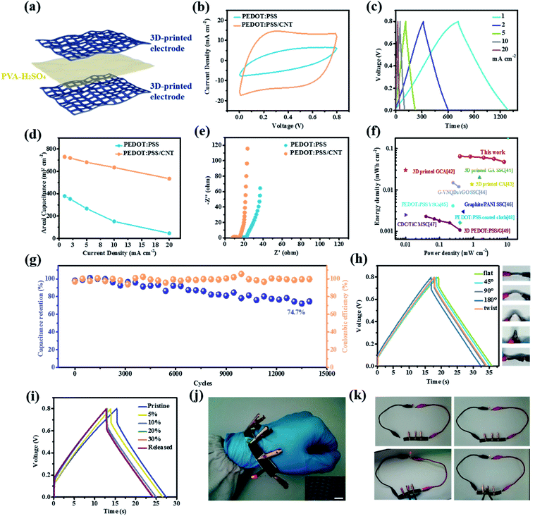
To prove the practical application of the 3D printed electrodes, a quasi-solid-sate PEDOT:PSS/CNT symmetric supercapacitor (SSC) was assembled. Fig. 6a shows the schematical diagram of a quasi-solid-sate PEDOT:PSS/CNT SSC, in which the PEDOT:PSS/CNT electrode was used as both the positive and negative electrode using PVA/H2SO4 as gel electrolyte. Based on the intrinsic capacitance behavior of PEDOT:PSS, the quasi-solid-sate SSC based on pristine PEDOT:PSS exhibits good electrochemical performance (Fig. 6b and S10a†). After the addition of the CNT, the capacitance of the quasi-solid-sate SSC was further increased. Fig. S10c† reveals that the PEDOT:PSS/CNT SSC presents an ideal capacitive behavior, with quasi-rectangular CV curves at different scan rates ranging from 10 to 70 mV s−1. In addition, the triangular shape of GCD curves also reveals the typical capacitive characteristics and efficient charge storage ability of the two devices (Fig. 6c and S10b†). Based on the GCD curves, the PEDOT:PSS/CNT SSC achieves high area capacitance of 730 mF cm−2 at 1 mA cm−2 and 535 mF cm−2 at 20 mA cm−2 (Fig. 6d), which are better than those for PEDOT:PSS SSC (379 mF cm−2 at 1 mA cm−2 and 47 mF cm−2 at 20 mA cm−2). The PEDOT:PSS/CNT SSC also shows superior electrical conductivity with a smaller semicircular curve in the EIS results in Fig. 6e. As shown in Fig. 6f, the PEDOT:PSS/CNT SSC exhibits an energy density of 0.065 mW h cm−2 at a power density of 0.4 mW cm−2, and maintains an energy density of 0.048 mW h cm−2 at a power density of 8 mW cm−2. The values are better than those of many previously reported supercapacitors based on conducting polymer materials or prepared by 3D printing technology.41–49 As shown in Fig. 6g, the PEDOT:PSS/CNT SSC also exhibits ultra-long stability that it can maintain 74.7% of its initial capacitance even after 14![[thin space (1/6-em)]](https://www.rsc.org/images/entities/char_2009.gif) 000 cycles of charge and discharge. The mechanical properties of such a 3D-printed electrode are essential for their practical application in the field of wearable electronics. Therefore, the electrochemical performance of the PEDOT:PSS/CNT SSC under different stress states was further investigated. As shown in Fig. 6h, although the capacitance will be affected by external deformation conditions, PEDOT:PSS/CNT SSC can still maintain 93% of its initial capacitance at the bending state of 180°, and 97% of the initial capacity under twisting conditions. In addition, the supercapacitor still maintains its electrochemical performance when it is subjected to different stretching strains (Fig. S10d†). As depicted in Fig. 6i, during the stretch-relaxation cycle in which the strain was gradually increased from 10% to 30%, the capacitance of the stretchable supercapacitors exhibits little variation. The SSCs are able to maintain energy output for a LED without difficulty (Fig. 6j). Four PEDOT:PSS/CNT SSCs connected in series were used to light up a LED (Fig. 6k), and the brightness of the LED remains unchanged during the various deformation process (Video 4, ESI†).
000 cycles of charge and discharge. The mechanical properties of such a 3D-printed electrode are essential for their practical application in the field of wearable electronics. Therefore, the electrochemical performance of the PEDOT:PSS/CNT SSC under different stress states was further investigated. As shown in Fig. 6h, although the capacitance will be affected by external deformation conditions, PEDOT:PSS/CNT SSC can still maintain 93% of its initial capacitance at the bending state of 180°, and 97% of the initial capacity under twisting conditions. In addition, the supercapacitor still maintains its electrochemical performance when it is subjected to different stretching strains (Fig. S10d†). As depicted in Fig. 6i, during the stretch-relaxation cycle in which the strain was gradually increased from 10% to 30%, the capacitance of the stretchable supercapacitors exhibits little variation. The SSCs are able to maintain energy output for a LED without difficulty (Fig. 6j). Four PEDOT:PSS/CNT SSCs connected in series were used to light up a LED (Fig. 6k), and the brightness of the LED remains unchanged during the various deformation process (Video 4, ESI†).
Conclusions
In summary, a stretchable conducting polymer electrode has been prepared using extrusion 3D printing technology in combination with rational structural patterning. As demonstrated by both tensile tests and mechanical simulations, the optimised arc-shaped NPR structure provided effective strain and stress relief for the electrodes. The 3D-printed conducting polymer electrode can still maintain structural integrity when stretched to 150% or bent to 180°. Apart from mechanical flexibility, the optimized electrodes also exhibited satisfactory electrochemical performance with a high areal capacitance of 990 mF cm−2. The quasi-solid-state symmetric supercapacitor assembled from 3D-printed electrodes also demonstrated promising areal capacitance and unprecedented long-term cycling stability (74.7% capacity retentions after 14![[thin space (1/6-em)]](https://www.rsc.org/images/entities/char_2009.gif) 000 cycles). The facile and highly scalable fabrication process, together with the excellent mechanical and electrochemical performance of the stretchable conducting polymer electrodes would provide a promising step towards the application of various flexible electronic devices.
000 cycles). The facile and highly scalable fabrication process, together with the excellent mechanical and electrochemical performance of the stretchable conducting polymer electrodes would provide a promising step towards the application of various flexible electronic devices.
Conflicts of interest
There are no conflicts to declare.Acknowledgements
The authors acknowledge the support by the National Natural Science Foundation of China (Grant No. 51902265), Key Research and Development Program of Shaanxi (Program No. 2020KWZ-001), Fundamental Research Funds for the Central Universities, and Project for Graduate Innovation Team of Northwestern Polytechnical University. The authors also acknowledge the support by the Analytical and Testing Center of Northwestern Polytechnical University for SEM and TEM.References
- S. Zhang, H. Ling, Y. Chen, Q. Cui, J. Ni, X. Wang, M. C. Hartel, X. Meng, K. Lee, J. Lee, W. Sun, H. Lin, S. Emaminejad, S. Ahadian, N. Ashammakhi, M. R. Dokmeci and A. Khademhosseini, Adv. Funct. Mater., 2019, 30, 1906016 Search PubMed
.
- E. Davoodi, H. Montazerian, R. Haghniaz, A. Rashidi, S. Ahadian, A. Sheikhi, J. Chen, A. Khademhosseini, A. S. Milani, M. Hoorfar and E. Toyserkani, ACS Nano, 2020, 14, 1520–1532 Search PubMed
.
- A. Muhulet, F. Miculescu, S. I. Voicu, F. Schütt, V. K. Thakur and Y. K. Mishra, Mater. Today Energy, 2018, 9, 154–186 Search PubMed
.
- J. Du, Q. Cao, X. Tang, X. Xu, X. Long, J. Ding, C. Guan and W. Huang, Chem. Eng. J., 2021, 416, 127885 Search PubMed
.
- Q. Cao, J. Du, X. Tang, X. Xu, L. Huang, D. Cai, X. Long, X. Wang, J. Ding, C. Guan and W. Huang, Research, 2020, 2020, 7304767 Search PubMed
.
- Y. Wang, Q. Cao, C. Guan and C. Cheng, Small, 2020, 16, 2002902 Search PubMed
.
- C. Guan, W. Zhao, Y. Hu, Q. Ke, X. Li, H. Zhang and J. Wang, Adv. Energy Mater., 2016, 6, 1601034 Search PubMed
.
- X. Li, H. Li, X. Fan, X. Shi and J. Liang, Adv. Energy Mater., 2020, 10, 1903794 Search PubMed
.
- C. R. Chen, H. Qin, H. P. Cong and S. H. Yu, Adv. Mater., 2019, 31, 1900573 Search PubMed
.
- K. Xu, H. Shao, Z. Lin, C. Merlet, G. Feng, J. Zhu and P. Simon, Energy Environ. Mater., 2020, 3, 235–246 Search PubMed
.
- Q. Dou and H. S. Park, Energy Environ. Mater., 2020, 3, 286–305 Search PubMed
.
- F. Chen, H. Wang, S. Ji, V. Linkov and R. Wang, Mater. Today Energy, 2019, 11, 211–217 Search PubMed
.
- B. Yao, S. Chandrasekaran, J. Zhang, W. Xiao, F. Qian, C. Zhu, E. B. Duoss, C. M. Spadaccini, M. A. Worsley and Y. Li, Joule, 2019, 3, 459–470 Search PubMed
.
- B. Yao, S. Chandrasekaran, H. Zhang, A. Ma, J. Kang, L. Zhang, X. Lu, F. Qian, C. Zhu, E. B. Duoss, C. M. Spadaccini, M. A. Worsley and Y. Li, Adv. Mater., 2020, 32, 1906652 Search PubMed
.
- Z. Lyu, G. J. H. Lim, R. Guo, Z. Kou, T. Wang, C. Guan, J. Ding, W. Chen and J. Wang, Adv. Funct. Mater., 2019, 29, 1806658 Search PubMed
.
- P. Wu, Z. Fang, A. Zhang, X. Zhang, Y. Tang, Y. Zhou and G. Yu, Research, 2019, 2019, 8393085 Search PubMed
.
- Z. Qi and H. Wang, Research, 2020, 2020, 2969510 Search PubMed
.
- T. Meng, J. Gao, J. Zhu, N. Li, M. Xu, C. M. Li and J. Jiang, J. Mater. Chem. A, 2020, 8, 11976–11985 Search PubMed
.
- J. Zhao, Y. Zhang, X. Zhao, R. Wang, J. Xie, C. Yang, J. Wang, Q. Zhang, L. Li, C. Lu and Y. Yao, Adv. Funct. Mater., 2019, 29, 1900809 Search PubMed
.
- L. V. Kayser and D. J. Lipomi, Adv. Mater., 2019, 31, 1806133 Search PubMed
.
- K. Keum, J. W. Kim, S. Y. Hong, J. G. Son, S. S. Lee and J. S. Ha, Adv. Mater., 2020, 32, 2002180 Search PubMed
.
- T. Li, Y. Chen, X. Hu, Y. Li and L. Wang, Mater. Des., 2018, 142, 247–258 Search PubMed
.
- K. Chatterjee and T. K. Ghosh, Adv. Mater., 2020, 32, e1902086 Search PubMed
.
- S. Huang, Y. Liu, Y. Zhao, Z. Ren and C. F. Guo, Adv. Funct. Mater., 2018, 29, 1805924 Search PubMed
.
- Y. Bao, Y. Liu, Y. Kuang, D. Fang and T. Li, Energy Storage Mater., 2020, 33, 55–61 Search PubMed
.
- E. Khare, S. Temple, I. Tomov, F. Zhang and S. K. Smoukov, Front. Mater., 2018, 5, 45 Search PubMed
.
- L. Weng, C. Xu, B. Chen, J. Zhou, R. Cai and Y. Shi, Mech. Mater., 2020, 150, 103567 Search PubMed
.
- C. Huang and L. Chen, Adv. Mater., 2016, 28, 8079–8096 Search PubMed
.
- Y. Wen, E. Gao, Z. Hu, T. Xu, H. Lu, Z. Xu and C. Li, Nat. Commun., 2019, 10, 2446 Search PubMed
.
- Y. Fan, Y. Xiang and H. S. Shen, Research, 2020, 2020, 5618021 Search PubMed
.
- P. Chang, H. Mei, Y. Tan, Y. Zhao, W. Huang and L. Cheng, J. Mater. Chem. A, 2020, 8, 13646–13658 Search PubMed
.
- H. Yuk, B. Lu, S. Lin, K. Qu, J. Xu, J. Luo and X. Zhao, Nat. Commun., 2020, 11, 1604 Search PubMed
.
- Y. Zhou, K. Maleski, B. Anasori, J. O. Thostenson, Y. Pang, Y. Feng, K. Zeng, C. B. Parker, S. Zauscher, Y. Gogotsi, J. T. Glass and C. Cao, ACS Nano, 2020, 14, 3576–3586 Search PubMed
.
- Y. Z. Zhang, Y. Wang, T. Cheng, L. Q. Yao, X. Li, W. Y. Lai and W. Huang, Chem. Soc. Rev., 2019, 48, 3229–3264 Search PubMed
.
- Y. Yan, X. Liu, J. Yan, C. Guan and J. Wang, Energy Environ. Mater., 2020 DOI:10.1002/eem2.12146
.
- C. J. Zhang, L. McKeon, M. P. Kremer, S. H. Park, O. Ronan, A. Seral-Ascaso, S. Barwich, C. O. Coileain, N. McEvoy, H. C. Nerl, B. Anasori, J. N. Coleman, Y. Gogotsi and V. Nicolosi, Nat. Commun., 2019, 10, 1795 Search PubMed
.
- V. Egorov, U. Gulzar, Y. Zhang, S. Breen and C. O’Dwyer, Adv. Mater., 2020, 32, 2000556 Search PubMed
.
- T. Gao, Z. Zhou, J. Yu, J. Zhao, G. Wang, D. Cao, B. Ding and Y. Li, Adv. Energy Mater., 2019, 9, 1802578 Search PubMed
.
- J. Zhu, Q. Zhang, T. Yang, Y. Liu and R. Liu, Nat. Commun., 2020, 11, 3462 Search PubMed
.
- J. Orangi, F. Hamade, V. A. Davis and M. Beidaghi, ACS Nano, 2020, 14, 640–650 Search PubMed
.
- X. Tang, H. Zhou, Z. Cai, D. Cheng, P. He, P. Xie, D. Zhang and T. Fan, ACS Nano, 2018, 12, 3502–3511 Search PubMed
.
- C. Zhu, T. Liu, F. Qian, T. Y. Han, E. B. Duoss, J. D. Kuntz, C. M. Spadaccini, M. A. Worsley and Y. Li, Nano Lett., 2016, 16, 3448–3456 Search PubMed
.
- K. Shen, J. Ding and S. Yang, Adv. Energy Mater., 2018, 8, 1800408 Search PubMed
.
- S. Yuan, W. Fan, D. Wang, L. Zhang, Y.-E. Miao, F. Lai and T. Liu, J. Mater. Chem. A, 2021, 9, 423–432 Search PubMed
.
- D. Yuan, B. Li, J. Cheng, Q. Guan, Z. Wang, W. Ni, C. Li, H. Liu and B. Wang, J. Mater. Chem. A, 2016, 4, 11616–11624 Search PubMed
.
- B. Yao, L. Yuan, X. Xiao, J. Zhang, Y. Qi, J. Zhou, J. Zhou, B. Hu and W. Chen, Nano Energy, 2013, 2, 1071–1078 Search PubMed
.
- C. L. P. Huang, S. Pinaud, K. Brousse, R. Laloo, V. Turq, M. Respaud, A. Demortière, B. Daffos and P. L. Taberna, Science, 2016, 351, 691–695 Search PubMed
.
- L. Manjakkal, A. Pullanchiyodan, N. Yogeswaran, E. S. Hosseini and R. Dahiya, Adv. Mater., 2020, 32, 1907254 Search PubMed
.
- W. Yan, J. Li, G. Zhang, L. Wang and D. Ho, J. Mater. Chem. A, 2020, 8, 554–564 Search PubMed
.
Footnote |
| † Electronic supplementary information (ESI) available. See DOI: 10.1039/d1ta02617h |
| This journal is © The Royal Society of Chemistry 2021 |

