 Open Access Article
Creative Commons Attribution 3.0 Unported Licence
Water electrolysis: from textbook knowledge to the latest scientific strategies and industrial developments†
Marian
Chatenet
 a,
Bruno G.
Pollet
 bc,
Dario R.
Dekel
 de,
Fabio
Dionigi
 f,
Jonathan
Deseure
 a,
Pierre
Millet
 gh,
Richard D.
Braatz
 i,
Martin Z.
Bazant
 ij,
Michael
Eikerling
 kl,
Iain
Staffell
 m,
Paul
Balcombe
 n,
Yang
Shao-Horn
 o and
Helmut
Schäfer
 *p
*p
aUniversity Grenoble Alpes, University Savoie Mont Blanc, CNRS, Grenoble INP (Institute of Engineering and Management University Grenoble Alpes), LEPMI, 38000 Grenoble, France
bHydrogen Energy and Sonochemistry Research group, Department of Energy and Process Engineering, Faculty of Engineering, Norwegian University of Science and Technology (NTNU) NO-7491, Trondheim, Norway
cGreen Hydrogen Lab, Institute for Hydrogen Research (IHR), Université du Québec à Trois-Rivières (UQTR), 3351 Boulevard des Forges, Trois-Rivières, Québec G9A 5H7, Canada
dThe Wolfson Department of Chemical Engineering, Technion – Israel Institute of Technology, Haifa, 3200003, Israel
eThe Nancy & Stephen Grand Technion Energy Program (GTEP), Technion – Israel Institute of Technology, Haifa 3200003, Israel
fDepartment of Chemistry, Chemical Engineering Division, Technical University Berlin, 10623, Berlin, Germany
gParis-Saclay University, ICMMO (UMR 8182), 91400 Orsay, France
hElogen, 8 avenue du Parana, 91940 Les Ulis, France
iDepartment of Chemical Engineering, Massachusetts Institute of Technology, Cambridge, Massachusetts 02139, USA
jDepartment of Mathematics, Massachusetts Institute of Technology, 77 Massachusetts Avenue, Cambridge, Massachusetts 02139, USA
kChair of Theory and Computation of Energy Materials, Division of Materials Science and Engineering, RWTH Aachen University, Intzestraße 5, 52072 Aachen, Germany
lInstitute of Energy and Climate Research, IEK-13: Modelling and Simulation of Materials in Energy Technology, Forschungszentrum Jülich GmbH, 52425 Jülich, Germany
mCentre for Environmental Policy, Imperial College London, London, UK
nDivision of Chemical Engineering and Renewable Energy, School of Engineering and Material Science, Queen Mary University of London, London, UK
oResearch Laboratory of Electronics and Department of Mechanical Engineering, Massachusetts Institute of Technology, Cambridge, Massachusetts 02139, USA
pInstitute of Chemistry of New Materials, The Electrochemical Energy and Catalysis Group, University of Osnabrück, Barbarastrasse 7, 49076 Osnabrück, Germany. E-mail: helmut.schaefer@uos.de
First published on 16th May 2022
Abstract
Replacing fossil fuels with energy sources and carriers that are sustainable, environmentally benign, and affordable is amongst the most pressing challenges for future socio-economic development. To that goal, hydrogen is presumed to be the most promising energy carrier. Electrocatalytic water splitting, if driven by green electricity, would provide hydrogen with minimal CO2 footprint. The viability of water electrolysis still hinges on the availability of durable earth-abundant electrocatalyst materials and the overall process efficiency. This review spans from the fundamentals of electrocatalytically initiated water splitting to the very latest scientific findings from university and institutional research, also covering specifications and special features of the current industrial processes and those processes currently being tested in large-scale applications. Recently developed strategies are described for the optimisation and discovery of active and durable materials for electrodes that ever-increasingly harness first-principles calculations and machine learning. In addition, a technoeconomic analysis of water electrolysis is included that allows an assessment of the extent to which a large-scale implementation of water splitting can help to combat climate change. This review article is intended to cross-pollinate and strengthen efforts from fundamental understanding to technical implementation and to improve the ‘junctions’ between the field's physical chemists, materials scientists and engineers, as well as stimulate much-needed exchange among these groups on challenges encountered in the different domains.
1 Introduction
All our environmental problems are compounded with a growing population.1,2 Population increases the greenhouse gas production due to increasing livestock husbandry and the gigantic hunger of the population for electrical energy, the production of which releases carbon dioxide (Fig. 1a).3 The world energy demand is predicted to double by 2050 and triple by the end of the 21st century.4 The accelerated depletion of fossil fuels and ecological consequences associated with their use are a major concern of both policy makers and the public. Thus, the global energy consumption by energy source will have to change drastically in the next decades (Fig. 1b) and scientists and engineers are forced to search for green energy carriers, i.e., produced using zero-carbon renewable energy resources like wind, solar, hydropower or geothermal.5,6 Solar energy however suffers from intermittent availability due to regional or seasonal factors – a drawback that makes it difficult to adapt to the demands of a modern society.7,8 Energy conversion, and in particular energy storage, will therefore be an essential pillar in allowing energy to be harvested where and when needed. Compared to electrochemical storage (e.g., in Li-ion batteries), storing energy in the bonds of molecules such as hydrogen does not suffer from self-discharge (energy loss) during the storage period. Hydrogen (H2) has future potential as an energy carrier due to its high energy content and harmless burning products. The energy can be subsequently regenerated by fuel cells. In addition, H2 could be easily integrated to existing distribution systems for gas and oil.9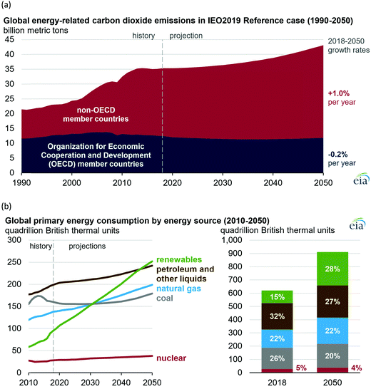 | ||
| Fig. 1 (a) Global carbon dioxide emissions; (b) global primary energy consumption by energy source. Source: ref. 19. | ||
However, hydrogen can only be seen as a green energy carrier when its generation is not fraught with the release of greenhouse gases. Hydrogen is currently produced almost entirely from fossil fuels, with 6% of global natural gas and 2% of global coal being used for hydrogen, and therefore it is responsible for CO2 emissions of around 830 million tonnes of carbon dioxide per year.10
A sustainable energy industry based on hydrogen is currently only being implemented slowly by society. National and international efforts are necessary and are already ongoing to pave the way for hydrogen as the main energy carrier of the future.10 Several countries and regions now have ambitious targets for the share of electricity coming from low-carbon sources, with South Australia aiming for 100% by 2025, Fukushima Prefecture by 2040, Sweden by 2040, California by 2045, and Denmark by 2050.10
Splitting of water into hydrogen and oxygen by exploiting solar energy transforms water into an inexhaustible and environmentally friendly fuel source.11–16 Among the known strategies, water electrolysis is the easiest technology to be transferred to large-scale industry.17,18
Electricity-driven water splitting comprises two half-cell reactions, the hydrogen evolution reaction (HER) and the oxygen (O2) evolution reaction (OER). Oxygen-evolving electrodes contribute mainly to the surplus of cell voltage which must be applied in addition to the theoretical decomposition voltage (1.229 V in standard conditions) of water electrolysis. Fig. 2 shows the Pourbaix diagram of water (potential pH diagram at standard conditions). HER and OER fundamentals are discussed in Section 2 of this review.
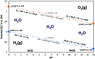 | ||
| Fig. 2 Water electrolysis electrode potentials with pH at standard conditions. Reproduced with permission from ref. 86. Wiley 2020. | ||
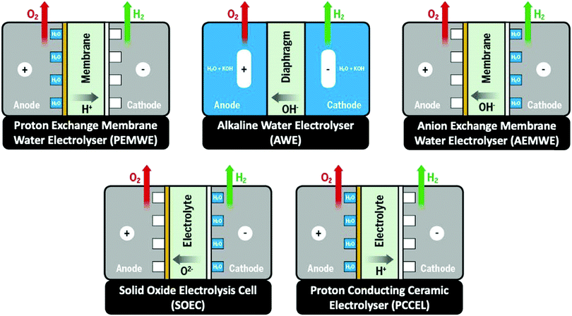
Besides alkaline water electrolyser (AWE),17 proton-exchange membrane (PEM) water electrolysers20 (PEMWE) and most recently anion-exchange membrane (AEM) water electrolysers21 (AEMWE) are currently well-developed and commercially available. Section 3 gives an overview of the water electrolyser technologies. Unlike AWE, PEMWE is compatible with frequent changes of the current load, a crucial characteristic when converting energy from a renewable source of electricity. All these technologies have their advantages and disadvantages, and the challenges for reducing the costs of produced hydrogen really are technology-depending. The membrane material represents an enormous cost driver for PEM technology;however, for PEMWE developing earth-abundant, durable electrode materials capable of replacing noble electrodes is currently the most effective way to reduce capital costs (capital expenditure, CAPEX). For AEMWE electrolysers, the maintenance costs caused by the poor stability of the membranes are the main cost factor. To bring clarity here, the different approaches are compared based on a (in-depth) techno-economic and SWOT (Strengths, Weakness Opportunities, and Threats) analysis (Sections 4 and 14), while Section 5 focuses on the materials of these water electrolysers’ technologies.
The usefulness of electrocatalytically-driven H2/O2 production stands and falls with complementary properties that must be met by the electrolyzer system. The efficiency, the rate and the stability of the system and its core materials are pivotal to its practical implementation. From an engineering standpoint, a system operated at a low overpotential (and low rate) would exhibit a high efficiency (low operating cost), combined with a low productivity (little hydrogen production in comparison to the total cost of the construction: high capital cost), maintenance and operation of the system, so that it will not always be economically competitive. On the contrary, a system running at higher rate (and a lower efficiency), could be more economically-viable per produced kg of hydrogen. In addition, the system stability must be considered, as long-lasting electrodes would enable to lower the maintainence/replacement costs. So, it is not only the electrodes/electrocatalysts’ efficiency which drive the electrolyser's practicability. However, one can admit that more efficient electrodes/electrocatalysts are still desperately needed; the electrocatalytic efficiency is directly determined by the overpotentials (η) occurring on both half-cell sides.22,23 It is therefore not surprising that optimisation of hydrogen-evolving and oxygen-evolving electrodes remains a hard-fought battlefield on which scientists and engineers currently cavort.
Especially of interest is the development of OER electrodes that consist of cheap, non-noble earth-abundant elements capable of replacing the noble, rarely occurring components such as iridium (Ir), platinum (Pt), or ruthenium (Ru) known to be highly active oxygen evolving electrodes. We would like to point out here that the periphery of the as-prepared electrode, i.e., the as prepared catalyst, is usually not identical with the active catalytic surface that is formed under operation. Today's materials discovery strategies based on first-principles calculations (e.g., DFT), machine learning, and optimisation approaches (aka the materials-by-design approach) for reducing the overpotential for metal-based and metal-free OER and HER electrocatalysts are evaluated in Sections 6–8.
For a general assessment of the quality of water electrolysis electrodes, it is not enough to consider only the pure electrocatalytic performance of the materials from which the electrodes are made. The number of active sites and the activity of the active site (the latter being defined as the intrinsic catalyst activity24) of the exploited materials play a major role in terms of the overall catalyst's performance and are influenced by particle size,25 by engineering catalyst morphology,26 and by surface reconstruction into more active site species.27–31 For tailored electrocatalytic properties and advantageous mass-transfer behaviour, optimised electrode preparation techniques and options for post-treatment of electrode materials and ready-to-use electrodes are essential (Section 9).
Water-splitting approaches that can be classified as being heterogenous catalysis are the most promising. Molecular catalysts originally intended to support photocatalytic water-splitting are also gradually implemented in water electrocatalysis (heterogenisation of molecular catalysts). Metal complexes can help not only in the understanding of the sequential steps of water oxidation but also have promise for their putative integration in functional devices, particularly for the hydrogen production reaction32 (Section 10).
A knowledge-based optimisation of electrodes would have been impossible without the development of ever finer characterisation methods, some of which being applied under potential control (i.e. in situ or even operando). X-ray photoelectron spectroscopy (XPS), Extended X-Ray Absorption Fine Structure (EXAFS), and X-ray Absorption Near Edge Structure (XANES) analysis helped to understand the characteristics that affect OER activity and are therefore vital for determining the OER mechanism and developing OER electrocatalysts. Often catalysts that appeared to be initially promising have failed when used at conditions approaching normal industrial operation. To evaluate the value of electrode materials or complete water-splitting devices in terms of practical application, intensive ex situ/in situ testing and durability (long-term) testing under conditions ranging from classical laboratory operating settings (current density loads, temperature, load change behaviour) to industrial settings are an indispensable prerequisite. It is widely agreed that dynamic conditions (e.g., cycling the electrode potential or current density) accelerate the degradation relative to galvanostatic testing which led to the so-called accelerated durability tests (ADT).33,34 In terms of the durability of fuel cells, steady progress has been made towards the Department of Energy (DOE) MYRD&D 2020 target of 5000 hours with less than 10% loss of performance (with an ultimate target of 8000 hours at 10% loss of performance).35 The challenge today is to have PEMFCs (proton exchange membrane fuel cells) for heavy-duty vehicles with 40![[thin space (1/6-em)]](https://www.rsc.org/images/entities/char_2009.gif) 000–50
000–50![[thin space (1/6-em)]](https://www.rsc.org/images/entities/char_2009.gif) 000 hours of service.36 PEM (proton exchange membrane) electrolyser components also degrade upon usage, but this is less of a concern as ∼60
000 hours of service.36 PEM (proton exchange membrane) electrolyser components also degrade upon usage, but this is less of a concern as ∼60![[thin space (1/6-em)]](https://www.rsc.org/images/entities/char_2009.gif) 000 hours lifetime has been reported in commercial stacks without any detected voltage decay.37 To provide evidence-based scientific support to the European policymaking process, EU harmonised test protocols have been developed.38,39 The characterisation methods of water electrolysers and their constitutive materials are addressed in Section 11.
000 hours lifetime has been reported in commercial stacks without any detected voltage decay.37 To provide evidence-based scientific support to the European policymaking process, EU harmonised test protocols have been developed.38,39 The characterisation methods of water electrolysers and their constitutive materials are addressed in Section 11.
Thinking outside the box can be worthwhile if the problems of classical approaches that have existed for years cannot be completely or not satisfactorily solved. Non-classical water-splitting approaches such as ultrasound and magnetic field-assisted water electrolysis29 are reviewed in Section 12.
In order to avoid expensive pre-treatment of the water (depending on country specifications), the electrolyser technology must be adaptable to the water that is directly available in nature. The savings originating from not using a purification step could however be counterbalanced by the depreciated performances of the water electrolyzer when fed with impure water. Problematic ingredients of water from the sea, lakes, and rivers as well as wastewater pose major challenges for electrodes and membranes. This research field is addressed in Section 13, while market and cost issues are focused on in Section 14.
Water splitting is a research field of activity that is developing at breath-taking speed. Consequently, the number of papers that can be assigned to water splitting published per time has increased dramatically. This area of research must not lose sight of a critical review of the research approaches. The authors try at every point in the article to identify opportunities in approaches – including around basic research such as electrode development, approaches to developing theoretical explanations, and the technical implementation of newer research approaches – and perhaps even to uncover possible wrong turns.
2 Basic concepts in OER and HER electrocatalysis
A typical water electrolyser comprises three (main) components: an electrolyte, a cathode, and an anode. Energy supplied with an externally generated voltage that must exceed the equilibrium voltage of water splitting, decomposes water molecules into hydrogen gas in the hydrogen evolution reaction (HER) at the cathode and oxygen gas in the oxygen evolution reaction (OER) at the anode. The net reaction of water electrolysis is 2H2O → 2H2 + O2. The standard equilibrium voltage of the water electrolysis cell is U0 = 1.229 V (at T = 298 K, P = 1 atm and pH 0). It is related to the standard reaction Gibbs energy by the well-known relation ΔG0R = −nFU0, with the Faraday constant F = 96![[thin space (1/6-em)]](https://www.rsc.org/images/entities/char_2009.gif) 485 C mol−1 and the number of electrons converted per H2 molecule, n = 2. Here, U0 = E0,OER − E0,HER is the difference between standard electrode potentials at anode, E0,OER, and cathode, E0,HER, that would be measured under standard conditions, if the net reaction rate and the corresponding cell current density were exactly equal to zero. When conditions deviate from the standard conditions, the equilibrium voltage, Ueq is determined by U0 and an additional term that generally depends on the temperature as well concentrations, activities or partial pressures of reactant and product species, as described by the Nernst equation. In order to achieve a certain decomposition rate (current density) the cell voltage U should exceed the equilibrium voltage (U > Ueq). Because of the sluggishness of the OER, a significant departure (U − Ueq > 0.5 V) is required in order to attain technically relevant current densities on the order of 0.3 to 10 A cm−2, depending on the water electrolysis technology employed.
485 C mol−1 and the number of electrons converted per H2 molecule, n = 2. Here, U0 = E0,OER − E0,HER is the difference between standard electrode potentials at anode, E0,OER, and cathode, E0,HER, that would be measured under standard conditions, if the net reaction rate and the corresponding cell current density were exactly equal to zero. When conditions deviate from the standard conditions, the equilibrium voltage, Ueq is determined by U0 and an additional term that generally depends on the temperature as well concentrations, activities or partial pressures of reactant and product species, as described by the Nernst equation. In order to achieve a certain decomposition rate (current density) the cell voltage U should exceed the equilibrium voltage (U > Ueq). Because of the sluggishness of the OER, a significant departure (U − Ueq > 0.5 V) is required in order to attain technically relevant current densities on the order of 0.3 to 10 A cm−2, depending on the water electrolysis technology employed.
The electrode potential values required to achieve a certain net rate or current density of the water decomposition reaction depends strongly on the pH value. Oxygen-evolving electrodes, in particular, incur a significantly higher overpotential (ηOER = EOER − Eeq,OER) under neutral or acidic conditions than under alkaline conditions.40,41 The overpotential at hydrogen-evolving electrodes (ηHER = EHER − Eeq,HER) is higher in neutral and alkaline environments.42 The overall water decomposition reaction is the reverse process of the water production reaction in a hydrogen fuel cell, in which H2 flows around the anode to be oxidised in the hydrogen oxidation reaction (HOR) and O2 flows around the cathode to be reduced in the oxygen reduction reaction (ORR). The maximal terminal voltage Ut (under equilibrium condition at zero current) or equilibrium voltage of an oxyhydrogen fuel cell is identical to the minimal decomposition voltage of water electrolysis (Ut = U0 = 1.229 V under standard conditions). Depending upon the solution pH, different OER and HER water electrolysis half-cell reactions and different HOR and ORR fuel-cell half-cell reactions can be defined.43
Under acidic conditions for the OER, two water molecules are converted into four protons (H+) and one oxygen molecule. In neutral and alkaline media, the OER involves the oxidation of four hydroxide ions to water. The direct oxidation of hydroxide anions on the electrode might be favoured over that of neutral water molecules, due to attractive interactions between anions and the positive anode – an effect that depends on the surface charging relation of the (supported) electrocatalyst material and the corresponding local reaction environment established.44–46
The HER takes place at the negatively-charged cathode. When hydrated extra protons (hydronium ions) are available in significant concentrations in acidic electrolytes, they are the preferred reactant and are reduced, eventually leading to the formation of a hydrogen molecule from two protons and two electrons. However, in neutral and alkaline media, the concentration of protons is negligible compared to that of water, and the reduction of H2O molecules prevails. The HER requires two-electron transfer steps, whereas the OER comprises at least four steps, typically proton-coupled electron transfer (PCET) steps, and three reaction intermediates. The more complex reaction pathway of the OER causes a higher overall activation energy, thus resulting in the more sluggish reaction kinetics. Rationalising the complex reaction behaviour of the OER requires detailed mechanistic models and analytical concepts that will be discussed below.47,48
The energy efficiency of the water splitting reaction is defined as the ratio of the thermodynamic equilibrium cell voltage, Ueq = 1.229 V in standard conditions, to the real cell voltage, Ucell, measured at T,P,j operating conditions. Ucell is the sum of the thermodynamic equilibrium cell voltage, the overpotentials that stem from charge transfer reactions on anode and cathode sides, and ohmic losses due to ion migration in the electrolyte phase, and from other parasitic losses, e.g., via convection or diffusion or other metallic cell components, i.e., overall  .49 For example, when Ucell = 1.8 V, this yield an efficiency e = 1.229 V/1.8 V × 100 = 68.3% at the operating conditions of interest (assuming that the effect of operating temperature and pressure on Ueq can be neglected). Note: The specific energy consumption at U0 (under standard equilibrium conditions) is equal to 2.94 kW h m−3 H2′, and the one at Ucell = 1.8 V (a usual PEMWE cell voltage at beginning of life; j = 1 A cm−2, 60 °C)), is equal to 4.31 kW h m−3 H2. The efficiency can also be defined as ε = 2.94/4.31 × 100 = 68.3%.23,50 Although the assessment of energy consumption and efficiency of an electrolyser cell can be quite easily determined by the overvoltage beyond the theoretical equilibrium voltage (assuming 100% faradaic efficiency), knowing the overpotential losses from different cell components (anode, cathode, electrolyte) and energy loss processes (HER, OER, ion migration, diffusion) is a more precise methodology, that would enable to isolate/mitigate the cell limitations.
In the following, we will briefly discuss basic concepts and important parameters that determine the response functions between the electrode potentials, EOER (anode) or EHER (cathode) or total electrode overpotential, ηOER/HER = EOER/HER − Eeq,OER/HER, and the cell current density, j. This response function, also referred to as polarisation curve, is the characteristic function of an electrochemical cell.
The condition of electrochemical equilibrium for individual electrode configurations or electrochemical cells can be developed from the very basic concepts of electrochemical thermodynamics that are well-covered in numerous textbooks.43,51,52 The interested reader could find a concise treatment of the equilibrium thermodynamics of electrochemical cells in the chapter “Basic Concepts” of ref. 53 and recent extensions for nonequilibrium thermodynamics at high currents in ref. 54.
The flow of electric current influences the electrode potentials at anode and cathode for three reasons. Firstly, the kinetics of charge transfer at electrochemical interfaces is kinetically hindered and thus proceeds at a finite rate. A sufficient overvoltage must be applied to accelerate the charge transfer rate to the value required for achieving the target current density. Secondly, in order to supply electroactive species to the interface at the rate, at which they are being consumed, mass-transport limitations or resistances must be overcome. In water electrolysis, relevant transport processes involve charged ionic species, i.e., hydronium ions or hydroxide anions, and the voltage loss incurred by their transport requirements in liquid electrolyte, or polymer electrolyte membranes (AEM or PEM) and ionomer-impregnated electrodes, is described by Ohm's law that implies a linear relation between voltage loss and current density. Thirdly, the electronic conductors present on both sides of the interface cause further ohmic potential losses.
Depending on the value of the electrode potential relative to the equilibrium electrode potential, either the forward reaction or the reverse reaction of each electrode reaction is slowed down or accelerated. In this way, at the anode, the oxidation half-reaction will be accelerated by an electrode potential that exceeds the equilibrium potential of the OER, ηOER = EOER − Eeq,OER > 0, and at the cathode the reduction half-reaction will be accelerated by an electrode potential that is smaller than the equilibrium electrode potential of the HER, ηHER = EHER − Eeq,HER < 0. For an electrolysis cell, the terminal cell voltage is increased relative to the equilibrium cell voltage, Ut(I) > Ueq, by a sum that includes the absolute values of the electrode overpotentials, terms due to ohmic transport of ions and electrons, and other transport losses.
At practically-relevant current densities of water electrolysis, the evolution of oxygen and hydrogen involve the nucleation, growth, detachment and transport of gas bubbles. These processes cause further increases in the voltage losses associated with the reaction kinetics and ion transport. Bubbles that are attached to the catalyst surface diminish the effective activity and bubbles present in the electrolyte increase the ohmic losses associated with ionic transport in the electrolyte.
As stated above, the overpotential is connected to both the kinetics of charge-transfer and mass-transport. In the most rudimentary form, overvoltage's associated with the electrode kinetics can be related to the current density at an electrode by the Butler–Volmer equation,
 | (1) |
It should be noted, that albeit being well-known and widely used, the form of the BV equation provided above, is valid only for single outer-sphere electron transfer processes with complete elimination of any mass-transport effects – conditions that are hardly ever encountered in any technogically relevant electrochemical cell. In the more general case that applies to complex multistep reactions and to conditions with significant mass transport effects, which come into play when the absolute value of the overpotential η is large (η ≫ RT/F), the form of the BV equation could be – in principle – retained, but only the term with positive argument of the exponential function needs to be considered at the particular electrode considered (corresponding to the so-called Tafel behaviour). Moreover, due to mass transport effects, local concentrations of reactants (electroactive species) at the electrode surface must be accounted for, which depart significantly from the bulk values or the concentrations provided in external reservoirs. The relations between current density and overpotential in these general cases are:
 | (2) |
Looking deceptively simple in the form of eqn (2), the multistep character of reactions of interest in water electrolysis, especially the OER, will be hidden in two effective parameters (only considering the anode side here): the effective exchange current density, ja0,eff, and the effective transfer coefficient, αaeff. For the latter parameter, we may also introduce the Tafel slope,  . A microkinetic model of the ORR was solved in ref. 48 and the solution was cast into the form of eqn (2). The formalism was generalised in ref. 47, where the concept of a rate-determining term was presented and applied to the case of the OER. The detailed analyses provided in these recent works unravel the impact of the multistep character of ORR and OER and they reveal the price paid by casting the relation between current density and overpotential into the form of an “effective BV” equation: the two effective parameters ja/c0,eff and
  exhibit strong dependencies on electrode potential (or overpotential), cf.Fig. 6 in ref. 48. In the case of jc0,eff for the ORR, this dependence amounts to a variation by 10 orders of magnitude over the potential range relevant for the ORR. The Tafel slopes needed in eqn (2) vary in the range between 24 mV dec−1 at small overpotential and 120 mV dec−1 at large overpotential, as revealed by the analyses based on microkinetic modelling and also found in good agreement with experimental observations for ORR48 and OER.47 Any student or scholar who is beginning to scrutinise the vast experimental literature on the ORR (or OER) is likely to make a confusing experience: reported values for the exchange current density for this reaction seem to be inconsistent and varying by large factors across the literature screened. Ultimately, the multistep nature of the reaction and the oversimplification involved in forcing the complex kinetics of such a process into the form of eqn (2) is responsible for this frustrating experience. Given the strong dependence on the potential of the effective exchange current density and Tafel slope, it is expected that the values found from a Tafel-analysis will be highly sensitive to the range of electrode potentials considered for the fitting of experimental data.
To summarise, the HER and, to a very certain degree, OER are defined by charge transfer kinetics more than by thermodynamic restrictions and contribute mainly to the surplus of cell voltage which must be supplied by an external power source in addition to the theoretical decomposition voltage.55 The reactions are not severely mass-transport limited in a well-designed cell, except if bubbles are poorly managed, in particular in AWE.56,57 Besides compensation of activation barriers at the anode and cathode side caused by charge-transfer limitations, the overall overpotential results from solution and contact resistances. Activation barriers can be reduced by exploiting improved electrocatalysts suitable for OER and HER, whereas a clever cell design can substantially reduce Ohmic and mass-transport resistances.
Several reviews are discussing mechanisms of OER and HER.58–61 Different preparation methods for the generation of the same metal oxide may lead to different metal oxide structures, leading to other pathways for the OER and HER. The following section discusses reaction pathways and mechanistic details of OER and HER for heterogeneous water electrocatalysis. They are not easily transferable to homogeneous catalysts (molecular systems)62 or atomically-dispersed catalysts.63
2.1 Basic mechanisms of the oxygen evolution reaction
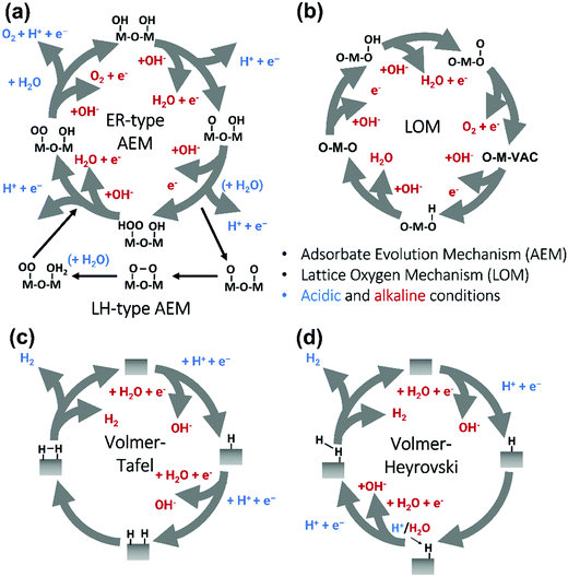
Pioneering studies by the groups of Hoare, Bard, Bockris, Conway, and several others64–68 showed that the voltage necessary to produce oxygen on a metal surface is related to the redox potential of the metal/metal oxide couple. In other words, even in the case of noble metals, no oxygen can be released from the surface if the corresponding metal oxide is not formed. As was confirmed by recent studies, the OER generally occurs on the hydroxide, oxyhydoxide or oxide layer formed in situ on the surface of the electrocatalyst.69The two generally accepted pathways for the OER in acidic conditions are the Eley–Rideal (ER)-type and the Langmuir–Hinshelwood (LH)-type adsorbate evolution reaction (AEM) mechanisms, illustrated in Scheme 1(a). The difference between the former (aka acid–base OER) and the latter (aka direct coupling OER) is in the O–O bond formation step.70,71 The OER reaction sequence is in all aqueous media initiated by the formation of metal hydroxide intermediates (MOH) subsequently converted to metal oxide species (MO). The formation of dioxygen starting from MO can occur through two different pathways. Either two MO centers are involved, directly splitting off dioxygen, or one MO intermediate reacts with water (acidic condition) or with OH− (alkaline or neutral condition) to give a hydroperoxide species that decompose under release of dioxygen.72 The nature of the OER mechanism strongly depends on the nature and structure of the catalyst at stake and any “easy generalisation” appears awkward, the same holding (if not more so) for the kinetics of the reaction. Both ER- and LH-type OER mechanisms involve four steps starting from the transformation of adsorbed OH (OH*) to O*, which results in the oxidation of the metal site.
The ER-type AEM mechanism assumes single metal cation active sites; thus, in the second step, O* undergoes the nucleophilic attack of the active first water molecule, resulting in the formation of OOH*. In the third step, OOH* further oxidises to OO*, which is released in the last step in the form of O2, providing the free surface site for the next cycle, starting with the adsorption of another water molecule. The LH-type AEM mechanism, on the other hand, assumes two adjacent metal cation active sites. Therefore, in the second step, OO* is formed between two O* species via the direct coupling of two neighbouring oxidised surface metal sites. Likewise, in alkaline conditions, the ER-type AEM involves the evolution from OH− reactant to OH*, O*, OOH*, OO* intermediates to O2 product on a single active metal site, while the LH-type AEM assumes that two adjacent metal sites are involved.73 As reviewed in ref. 71 the ER-type mechanism is reported for Ru-based catalysts,71,74 while there have been reports on LH-type mechanisms for Co-based catalysts,71,75
Pathways in AEM assume proton-coupled electron transfer (PCET) for all steps. For catalysts favouring these routes, the OER overpotential becomes pH-independent in the RHE scale, the case reported for Ir oxide catalysts.76 In contrast, the lattice oxygen mechanism (LOM) proceeds via non-concerted proton–electron transfer steps involving both the metal cation active site and the lattice oxygen. One proposed path for LOM involves five intermediates, viz. M–OH, M–O, M–OOH, M–OO, and M–ϒ (O represents the lattice oxygen), as illustrated in Scheme 1(b). In this picture, LOM is like LH-type AEM because both bypass the OOH* formation step. However, it differs from AEM in generating a vacant oxygen site upon the desorption of molecular oxygen from the surface. The non-concerted proton–electron transfer in LOM gives rise to pH-dependent OER kinetics, the phenomena observed in certain perovskite electrocatalysts77 as well as Ni oxyhydroxides.78,79 On the other hand, for RuO2 (110), the lattice oxygen is not involved in the OER.80
2.2 Basic mechanisms of the hydrogen evolution reaction
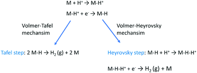
The HER is one of the most extensively studied electrochemical reactions due to its relative simplicity and its direct industrial relevance, not only in water electrolysis but also in chlor-alkali operations. In contrast to the sluggish kinetics of the OER and ORR,81,82 the kinetics of the HER on noble metal (platinum group metals, PGM) electrodes are much faster so that practical current densities (>1 A cm−2) are possible at a few tens of millivolts overpotential.83–85 The only exception is HER in an alkaline media (even on PGM surfaces42,86). The first investigations that aimed to clarify the mechanism of the HER on metal-based surfaces focused on nickel and date back to the early 1950s.87 The reaction sequence of the HER begins with the adsorption of a proton in case of acidic conditions (M–H+) or a water molecule in neutral or alkaline environment (M–HOH), followed by reduction of adsorbed water molecule/proton to form M–H* (and release OH− in case of the reduction of chemisorbed water). From this point onwards, two possible follow-up steps can be distinguished:88 (1) the combination of the chemisorbed Had with another chemisorbed H*, referred to as the Tafel step, which leads to the chemical desorption of H2,ad, or (2) electrochemical reaction of the chemisorbed proton with another proton or water molecule from solution, referred to as the Heyrovsky step, followed by further electrochemical discharge and desorption of H2. The former sequence of steps corresponds to the Volmer–Tafel mechanism89 whereas the latter is known as the Volmer–Heyrovsky mechanism.90,91Scheme 1(c) and (d) illustrates the two pathways for the HER under acidic and alkaline conditions, i.e., the Volmer–Tafel and the Volmer–Heyrovsky mechanisms, respectively.92,93 Both pathways start with the Volmer step, in which an electron transfer from the electrode is coupled with proton adsorption on the catalyst site to form an adsorbed H atom,
| H+ + e− → H* (in acidic electrolyte) | (3) |
| H2O + e− → OH− + H* (in alkaline electrolyte) | (4) |
Hydronium ions (H3O+) and water molecules are the source of protons in acidic and alkaline electrolytes, respectively. Next, in the Volmer–Tafel mechanism, the Tafel step combines two H* on adjacent sites to form H2, i.e.,
| H* + H* → H2 (in acidic and alkaline electrolytes) | (5) |
In the Heyrovsky step of the Volmer–Heyrovsky mechanism, H2 is formed via direct interaction of the H* atoms with protons (in acidic) and water molecules (in an alkaline environment),
| H* + H+ + e− → H2 (in acidic electrolyte) | (6) |
| H2O + e− → H2 + OH− (in alkaline electrolyte) | (7) |
Based on Scheme 2, one can easily understand that the M–H* bond strength will influence the catalytic activity of metal towards the HER. On the one hand, a substantial strength is required to support the formation of the M–H* bond, the first step that initiates the reaction sequence (Volmer). On the other hand, too strong M–H bonding is counterproductive, as chemisorbed intermediates or product species will not be easily released from the surface, thereby causing a surface blocking effect. This is the case for reduced Ni surfaces, which bind Had too strongly,91 whereas oxidised Ni surfaces present an intermediate and thus more “optimised” Ni–H bond strength that is beneficial for fast HER/HOR. Investigations confirmed that the catalytic activity toward the HER is correlated with the strength of the interaction between the catalyst surface and adsorbed hydrogen. At low overpotentials (at which HER usually occurs), the slope of the current–voltage curve is proportional to the exchange current density j0. Exchange current densities for the HER on pure metals in acidic media have been reported in a plethora of experimental studies, as collected and famously reported by Trasatti in ref. 98. Plotting these values against the metal-hydrogen bond strength revealed a characteristic behaviour that is known as the “volcano” curve (Fig. 3) and expected based on the Sabatier principle:99,100 the HER activity increases to a peak value obtained at medium bond strengths (Pt, Rh, Ir) then decreases again towards higher bond strengths. It should be mentioned at this point that the Trasatti volcano is only applicable to acidic media and requires an exchange current density correction for Pt.101
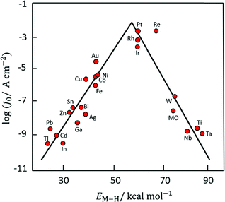 | ||
| Fig. 3 A common phenomenon in chemical catalysis is the volcano relationship between the catalytic activity of a particular reaction on the ordinate (on a log scale) and an activity descriptor on the abscissa. It is found that for a given reaction carried out on a variety of catalysts, the rates on each catalyst can be plotted so that they pass through a maximum. What is plotted on the abscissa varies, but it is always a function that includes a property of the catalyst (e.g., heat of sublimation, bonding strength of a reaction intermediate to the catalyst material). The volcano behaviour of the exchange current density of the hydrogen oxidation reaction vs. M–H bonding strength is generally valid for pure metals in acidic solution and was first determined by Trasatti 97. The noble metals Pt and Pd demonstrate exceptionally high activity, with Ni as the most active non-precious metal. Reproduced with permission from ref. 98 Copyright 1972 Elsevier. | ||
Pt group metals (PGM) are the most effective materials to catalyse the HER in acidic and alkaline conditions. Among the non-PGM class, sulphides, phosphides, carbides, and borides have shown promising HER activity, and these will be reviewed in the forthcoming sections.
In alkaline electrolysers, non-precious-transition metal oxides such as Co-, Ni-, and Fe-based materials are stable and active towards the OER (see Section 7), with Ni-based oxyhydroxides (NiOxHy) being among the best-performing OER catalysts under alkaline conditions. In situ surface spectroscopy study by Diaz-Morales et al. suggests a pH-dependency of the OER at NiOxHy materials, based upon which a mechanism was proposed that involves a non-concerted proton–electron transfer step. pH-Dependence at RHE scale is linked to surface deprotonation and formation of negatively-charged surface oxygen species, NiOO–, that are involved in the OER. DFT studies of the OER mechanism on β-NiOOH(0001) revealed the involvement of lattice oxygen in the mechanism; however, despite the experimental observation, PCET was assumed for all steps. A more recent experimental investigation by Koper et al. reported the effect of electrolyte alkali metal cations on the OER activity of these materials:79 the interaction of cations with negatively-charged surface oxygen species (NiOO−) stabilises cations on the surface. A thorough modelling investigation by Huang et al. explains the decrease in OER activity with the increasing effective size of electrolyte cations by a cation overcrowding-effect near the negatively-charged electrode surface.102
Incorporating Fe into NiOxHy materials, either intentionally via doping or incidentally due to iron ions formed during fabrication or operation of the electrochemical cell and entering the catalyst layer as impurities, significantly increase their OER activity.103,104 Controversial explanations were proposed to understand the role of Fe. From the simulation point of view, the controversy can originate at different levels. As an example, the well-known experimental-theoretical investigation by Friebel et al. observed the OER dependence on the Fe content and proposed Fe3+ as an active site in γ-FeNiOOH(01![[1 with combining macron]](https://www.rsc.org/images/entities/char_0031_0304.gif) 2).105 First, the choice of surface termination for the DFT study was explained based on its high activity; however, the (0001) facet is known to be the thermodynamically most stable facet; unlike on the high index facet, the mechanism of OER on the (0001) facet involves lattice oxygen.106 The calculations were performed in the gas phase; it is, however, known from studies using the DFT+U approach that water strongly interacts with NiOOH surfaces.107,108 The calculations in ref. 106, were performed at the PBE+U level, although it was shown that the PBE+U does not correctly describe the electronic structure of NiOOH and significantly underestimates the bandgap of the material.109 The γ-phase of FeNiOOH under OER conditions involves intercalated water and ionic species; Friebel et al. approximated the γ-phase with 50% dehydrogenated β-phase to obtain an average oxidation state of +3.5 consistent with γ-phase. Most importantly, the computational hydrogen electrode scheme was used to generate the OER energy diagram assuming that all steps involve PCET. However, there is experimental evidence against this assumption for this material. For example, similar to the conclusion by Koper et al.,78 Görlin et al. proposed a decoupled proton transfer–electron transfer scheme involving negatively-charged oxygenate ligands generated at Fe centers.110 In another study, Trotochaud et al. explored the activity-dependence of FeNiOOH on the film thickness. They proposed that Fe induces a partial charge on Ni activating it for the OER.104 At variance, Xiao et al. presented that O–O coupling at Ni-sites is involved, which requires the synergy from the mixed Ni–Fe site.111 Mössbauer spectroscopy study indicated the formation of Fe4+, but its role on OER is not clear.112 Finally, Qiu et al. suggested that Fe in NiFe LDHs acts as an agent that creates higher valence Ni in the created oxyhydroxides under OER conditions, resulting in enhanced OER properties.113 These studies suggest that the phenomenon driving the enhancement of the activity of FeNiOOH are probably linked to the interplay between Fe and Ni moieties, even though complete understanding is not fully reached yet.
2).105 First, the choice of surface termination for the DFT study was explained based on its high activity; however, the (0001) facet is known to be the thermodynamically most stable facet; unlike on the high index facet, the mechanism of OER on the (0001) facet involves lattice oxygen.106 The calculations were performed in the gas phase; it is, however, known from studies using the DFT+U approach that water strongly interacts with NiOOH surfaces.107,108 The calculations in ref. 106, were performed at the PBE+U level, although it was shown that the PBE+U does not correctly describe the electronic structure of NiOOH and significantly underestimates the bandgap of the material.109 The γ-phase of FeNiOOH under OER conditions involves intercalated water and ionic species; Friebel et al. approximated the γ-phase with 50% dehydrogenated β-phase to obtain an average oxidation state of +3.5 consistent with γ-phase. Most importantly, the computational hydrogen electrode scheme was used to generate the OER energy diagram assuming that all steps involve PCET. However, there is experimental evidence against this assumption for this material. For example, similar to the conclusion by Koper et al.,78 Görlin et al. proposed a decoupled proton transfer–electron transfer scheme involving negatively-charged oxygenate ligands generated at Fe centers.110 In another study, Trotochaud et al. explored the activity-dependence of FeNiOOH on the film thickness. They proposed that Fe induces a partial charge on Ni activating it for the OER.104 At variance, Xiao et al. presented that O–O coupling at Ni-sites is involved, which requires the synergy from the mixed Ni–Fe site.111 Mössbauer spectroscopy study indicated the formation of Fe4+, but its role on OER is not clear.112 Finally, Qiu et al. suggested that Fe in NiFe LDHs acts as an agent that creates higher valence Ni in the created oxyhydroxides under OER conditions, resulting in enhanced OER properties.113 These studies suggest that the phenomenon driving the enhancement of the activity of FeNiOOH are probably linked to the interplay between Fe and Ni moieties, even though complete understanding is not fully reached yet.
In addition to NiOx-based electrocatalysts, bimetallic cobaltite oxy-/thio-spinels114,115 as well as perovskite oxides with tuneable electronic structure properties, have recently attracted interest due to their promising OER activities.27 For the latter class, the OER proceeds via the LOM, and the structural changes under OER conditions lead to the formation of an oxy(hydroxide) surface layer that is highly OER-active.77 In contrast to the conventional explanations of OER activity based on the correlations in adsorption energies of intermediates, understanding the LOM mechanism on perovskites requires identifying correlations with surface reconstruction phenomena.
2.3 Challenges for theory and computation
In the context of PEMWE technology, the key practical question being asked is: how can the precious metal loading, concerning mainly Ir as a key component, and the corresponding cost of this scarce material in anodes for the OER be drastically reduced while meeting or exceeding performance, durability and lifetime targets?116–119 This specific problem, entails two general, closely-intertwined challenges: (i) to find a catalyst material with an ideal combination of high intrinsic electrocatalytic activity and chemical stability that is also inexpensive and environmentally-benign,20 and (ii) to optimise the design of the porous composite electrode that accommodates the catalyst120 to maximise the statistical utilisation (on a per-atom basis) of the catalyst and ensure uniform reaction conditions over the entire catalyst surface dispersed inside of this medium. Using experimental and modelling-based analyses of electrocatalytic performance and stability, candidate materials to be used as electrocatalyst and support can be identified. These pre-selected materials can be passed on for in-device testing and fabrication scale-up.There is thus an intricate interplay of intrinsic catalytic activity and multicomponent transport that is controlled by the selection and specifically tuned properties of catalyst and support materials and the electrode design. Theory and computation are needed to contribute fundamental understanding as well as modelling-based analytical tools to deconvolute and quantify different voltage loss contributions caused by ohmic transport of ions (hydronium or hydroxide ions), electrocatalytic activation, and gas removal from active catalyst surface sites. Complicating matters, all of these processes and associated voltage losses are affected by the dynamics of gas bubble nucleation, growth, coalescence, detachment, and transport.121,122 In particular, the latter aspect calls for game-changing progress in the rational design of gas-evolving electrodes with rapid gas bubble detachment and removal, as emphasised by Zeradjanin123,124 and Bernt et al.20
This section of the review article is not intended as a detailed review of the field of theory and computation in electrolysis research. Recent reviews and perspectives with a strong emphasis on atomic-scale simulations exist.125–133 The Sabatier principle and the volcano-type relationships that result from it, are concepts borrowed from the field of heterogeneous catalysis (i.e., dealing with solid-gas interfaces). Early atomistic simulations in the field of electrocatalysis (i.e., dealing with solid-liquid electrolyte interfaces) have essentially transferred these concepts over from heterogeneous catalysis. Such approaches have been remarkably successful126,127,129,134 considering the fact that they neglected essential physics of electrochemical interfaces. Aspects of surface morphology, i.e., addressing differences between idealized flat surfaces and those that have terraces and kinks are similar for heterogeneous catalysis and electrocatalysis. However, in the latter field a detailed theoretical understanding of the (sub-)nanoscale structure and properties of the electrochemical interface is needed.45,46,148 To evaluate, compare and select electrocatalyst materials for the OER (or the HER), it is of utmost importance to understand the local reaction environment that prevails at the interface (reaction plane) when the electrolysis cell is operated at a certain voltage. This local reaction environment is affected by the atomic-scale surface configuration of the catalyst, by the potential and pH-dependent formation of surface oxides (as rationalized in the form of Pourbaix diagrams),108 by the surface charging relation46 and by specific ionic effects.102,108
This section provides a perspective on what this field currently can or cannot contribute and along which directions it is advancing. It will survey efforts to devise a theoretical-computational framework that comprehensively rationalises potential-induced surface charging phenomena, local reaction conditions, and microkinetic mechanisms at heterogeneous electrochemical interfaces and links such efforts with the modelling of transport and reaction in porous composite electrodes.
2.4 What to expect from theory and computation in the field of water electrolysis
Theory and computation can support the development of highly-performing and durable electrocatalyst materials and electrode media for water electrolysis in the following three areas: (i) devise a set of theory-based activity and stability descriptors to steer efforts in materials discovery and inverse design,134–137 (ii) employ efficient computational tools based on artificial intelligence to rapidly search the complex parameter space138–144 in conjunction with advances in autonomous or self-driving laboratories144–146 and (iii) implement smart approaches in electrode design and fabrication based on knowledge of reaction mechanisms, pathways and local reaction conditions.147,148The local reaction environment (LRE) that prevails at the catalyst's surface under real operating conditions plays a central role in this endeavour. On the one hand, it is crucial to understand how the LRE depends on the operating regime, i.e., cell current density or cell voltage, and the externally-controlled parameters such as pressure and temperature – this is the challenge that porous electrode theory and modelling must address. On the other hand, the impact of the LRE on electrocatalytic reaction mechanism and pathways as well as kinetic rate constants must be rationalised – this task calls for concerted efforts in interface theory, microkinetic modelling, and quantum-mechanical (DFT-based) calculations of energy and interactions parameters that control surface adsorption states as well as reactive transformations between them.
Once the optimal LRE has been determined by connecting these aspects, electrode design and fabrication will aim to provide these conditions uniformly over all available catalyst surface sites dispersed in a porous composite electrode. The departure from optimally-uniform conditions can be quantified by calculating the effectiveness factor of catalyst utilisation, as demonstrated for cathode catalyst layers (CCLs) in PEM fuel cells.149–153 For CCLs in PEM fuel cells, well-established hierarchical models describe the interplay of transport and reaction at different structural levels, viz. (i) single pore, (ii) mesoscopic agglomerate of Pt nanoparticles, carbon-based support and dispersed ionomer aggregates, and (iii) macroscopic porous composite layer. This interplay determines distributions of reaction conditions and rates and the net activity of the CCL for the ORR.53,154 Using these approaches, the effectiveness factor of catalyst utilisation was found to lie in the range of 5 to 10%; it decreases with increasing current density of operation, corresponding to higher non-uniformity of reaction conditions and rate distributions.
An overall effectiveness factor of Pt utilisation in PEM fuel cells that accounts for statistical utilisation effects was determined to be even smaller, lying in the range of 1 to 4%.153 For PEMWE, a similar model-based calculation and assessment of effectiveness factors in Ir-based anodes have not been made, as electrode models that account for a hierarchy of transport and electrokinetic effects in porous electrodes have not been developed to a sufficient level of sophistication. However, it can be expected that the overall effectiveness factor of Ir-utilisation will be about as small, most likely even smaller, due to the less extensive efforts in CL design for PEMWE and to the fact that (at least present) IrO2 OER catalysts are unsupported and of larger particle size than present PtM/C-based ORR catalysts in PEMFCs.
The OER activity in the PEMWE anode is highly dependent on electronic interactions between the electrode material and reaction intermediates. Binding energies of reaction intermediates can thus be employed as viable descriptors for the comparative assessment or “screening” of electrocatalyst materials in terms of their activity for the OER. These energies can be calculated with quantum-mechanical simulations based on density functional theory (DFT).155–158
However, other effects related to the electrolyte composition, i.e., the type of solvent and the types and concentrations of ions, must be factored in when attempting to rationalise or predict catalytic activities computationally. These effects determine the local surface state and the near-surface conditions in the electrolyte and thereby exert crucial impacts on electrocatalytic activities of OER and HER.79,159–165 DFT-based studies rationalised the importance of cation effects on the HER activity of transition metal electrodes,166 and more recently for the OER activity of oxide electrodes.102,108
2.5 Understanding of the local reaction environment
In electrochemistry, theory and simulation of the structure and dynamics at electrified interfaces between a solid electrode and an electrolyte are of central importance.167 The main challenges are concerned with understanding how the metal-based electrode material, the water-based electrolyte, and the complex boundary region in-between these two media impact the energetics and dynamics of adsorption and charge-transfer processes, as considered in a recent review.195 Specific questions in this context focus on the following aspects: (i) how do adsorbed intermediates determine or affect pathways of multistep reactions and reactivity125 (ii) How do solvent species and ions in the near-surface region modulate interfacial properties and local reaction environment?148The theory of electrified interfaces168–170 is closely interwoven with theoretical electrocatalysis and charge-transfer theory.171–173 It draws upon large inventories of condensed matter physics, surface science, heterogeneous catalysis, and chemical kinetics.
First-principles computational methods in electrochemistry, with density functional theory (DFT) at their core, strive to decipher the complex relations among the atomic structure and composition of an electrocatalyst material, the energetics, and the reaction kinetics of electrochemical processes. Important steps reveal how surface impurities and chemisorbed species, including reaction intermediates, affect the pathways of multistep reactions and how solvent molecules and ions modulate interfacial properties and the LRE. Theoretical and computational approaches are required to provide distributions of the electric potential, ion concentrations, and solvent orientation or alignment in the near-surface region of the electrolyte that is termed the electrochemical double layer. The key response function or fingerprint of a particular interface configuration is the surface-charging relation, i.e., the relation between the excess surface charge density at the metal denoted σM, and the metal phase potential, ϕM, as explored in ref. 44–46.
Various innovative catalyst designs have helped improve Ir-based catalysts, the most important element for PEMWEs. Ir–Ir oxide core–shell concepts,174 alloys/bimetallic mixed oxides175 and inexpensive support materials176,177,1428 that prolong the lifetime178 have been explored. The crucial idea is to enhance the IrOx nanoparticle dispersion and the ratio of the active surface to the total mass of catalyst.179
For supported catalysts, the mechanism and strength of bond formation between nanoparticle and support material must be investigated. The bond strength between these subsystems can be tuned by support doping. Electrochemical conditions at the interface are modulated by the size, shape, and density of nanoparticles on the support. For systems of IrO2 nanoparticles deposited on antimony-doped tin oxide (ATO), a significant increase in OER activity has been observed.176,178,1428 This gain in OER activity cannot simply be explained as a geometric surface area enhancement effect achieved with the nanoparticle dispersion of the catalyst.179–181,1420 Understanding the impact of the oxide support's physical properties on the nanoparticles’ electrocatalytic activity is of crucial importance in this context. Explanations found in the literature often invoke a so-called metal support “interaction”.178,182–185 Charge transfer properties at the junction between active catalyst particle and electronic support may also be affected by a Schottky-type barrier. This resistive effect could exert a significant impact on the electrocatalytic activity.186
The origin of this MSI effect has remained poorly understood and thus controversial.178,183 Electronic equilibration in the catalyst-support system is supposed to play an important role.183–185 However, a consistent explanation should also account for simultaneous electrochemical equilibria at interfaces between metal, support material, and electrolyte.187 To date, the complex problem of the coupled electronic and electrochemical equilibria at the heterogeneous particle-support surface has not been solved.
2.6 Theoretical-computational workflow to decipher the OER
Over the last two decades, the DFT-based method, known as the Computational Hydrogen Electrode (CHE),82 has found wide application in the electrocatalysis community as a convenient tool to identify activity trends within a certain class of catalyst materials, including those for transition metals, alloys, or oxides for the OER,135,189,421 and the HER.190–192 Despite its assumptions and drastic simplifications to the real electrocatalytic system, this scheme has also been the standard approach to determine the stable interface structure under varying electrochemical environments, i.e., for generating surface Pourbaix diagrams under the OER/HER conditions,108,193,194 as well for the identification of active sites105 and the mechanistic understanding of reaction mechanisms.125However, the main challenge in theoretical and computational electrocatalysis is to move beyond commonly-made simplifying assumptions of the interface problem, such as those made in the CHE scheme. A systematic workflow to proceed in studying OER/HER is illustrated and described in Fig. 4.195 The approach combines DFT calculations with microkinetic modelling and the electric double layer theory to address the major complexities at the interface, including the nonlinear solvent polarisation and ion size effects, chemisorption and induced surface dipole effect and surface charging relation.46,48,102 The microkinetic modeling explicitly treats all elementary steps of the reaction and it rationalizes the effects of reaction intermediates and their surface coverages on the effective kinetic rate of the overall reaction, as worked out in detail in ref. 47 and 48.
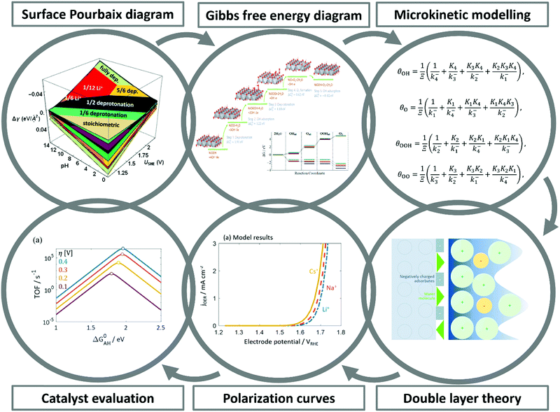 | ||
| Fig. 4 A theoretical-computational workflow to decipher the OER. Step 1. A DFT-based grand-canonical approach is developed to identify the surface adsorption state under relevant electrochemical conditions, i.e., through computing the surface Pourbaix diagram.108 Step 2. The OER reaction mechanism is identified and the Gibbs free energy diagram is generated using periodic DFT calculations.102 Step 3. A microkinetic model is formulated to obtain an expression for the net reaction rate.102 Step 4. The electrochemical interface model is solved to obtain the metal charging relation.46 The fully parameterised approach provides as output mechanistic insights as in Step 5 and 6, e.g., the rate-determining term in the net reaction rate;47 a descriptor-based activity assessment for materials screening; and effective parameters like Tafel-slope or exchange current density to use in porous electrode models.188 | ||
Pinpointing the most stable interface structure under relevant reaction conditions is an essential prerequisite to unraveling the local reaction environment for OER or HER and a requirement in connection with the studies on the kinetic processes involved in surface reactions. Therefore, the first step of the workflow combines the surface slab calculations in periodic DFT with thermodynamics to generate surface Pourbaix diagrams.193 Here, the Gibbs energy change associated with the formation of a specific surface configuration is given by,  where, ΔGad is the change in the Gibbs free energy due to adsorption,
  is the electrochemical potential of ions in the electrolyte, and ni is the number of adsorbed species of type, i. In this picture, the change in the adsorption Gibbs free energy is approximated by, ΔGad ≈ ΔEad + ΔZPE − TΔS. Here, ΔEad is the adsorbate binding energy calculated from DFT; ΔZPE, and TΔS are the zero-point energy entropy correction terms. ZPE is calculated from the harmonic oscillator approximation of adsorbates, and the total entropies for solvent are typically adopted from standard thermodynamic tables, while only the vibrational entropy contributions are accounted for the adsorbates.196
The grand-canonical variant of the CHE assumes that the electrode and the electrolyte are thermodynamic reservoirs for electrons and ions, respectively, whereas the reference system typically corresponds to the standard hydrogen electrode (SHE). At standard conditions, molecular hydrogen in the gas phase is in equilibrium with the solvated proton and the electron,  .
.
Therefore, for a proton-coupled electron transfer (PCET) step in thermodynamic equilibrium, the corresponding chemical potential of hydrogen in the gas phase is equal to that of a proton–electron pair.82 This way, one could refer the potential to the SHE or RHE scale and use the calculated gas-phase energy of molecular hydrogen to avoid the calculation of the proton solvation energy in water,
The second step of the above scheme entails calculating the Gibbs free energy change of each elementary step of the OER/HER and constructing the most favourable reaction pathway under standard conditions. The reference surface structure for this step should be obtained from the output of the first step. For quasi-equilibrium conditions at zero overpotential, all reaction intermediates forming under electrochemical conditions should have higher energy than the reference surface.198 The theoretical overpotential is then obtained from the step with the highest value of the reaction Gibbs energy,
So-called Volcano-type plots, based on the Sabatier principle, can be obtained by plotting ηth as a function of a simple descriptor like the adsorption energy of the critical intermediate132,410 For the OER, the adsorption energy of OOH* and OH* intermediates are linearly correlated, known as the scaling relation. Due to this universal correlation, the binding energy of these intermediates cannot be varied independently on the catalyst surface.199
The computational approaches described so far have been employed to rationalise the impact of materials modification strategies that aim to break the scaling relation at the interface and thereby reduce the overpotential. Surface alloying or doping the oxide material with a second metal provide different active sites for optimal binding of key intermediates and thus breaks the scaling relation for an increased catalyst activity. In a recent theory-experiment investigation, the cationic substitution of IrO2(100) with Ni was reported to enhance the OER activity of the catalyst.135 Rossmeisl and co-workers have shown this effect on Ru by incorporating Ni or Co into the surface.126 Buvat et al. reported an activity-dependence caused by the orthorhombic distortion of the tetragonal IrO2 due to the mismatch between the substrate and the catalyst thin-film at different temperatures.200 Other strategies include altering the electrolyte by adding promoters like cations,79 engineering the active site by designing novel catalysts like nano-frames,201 or applying interfacial nanoconfinement.202
The fundamental challenge for first principles studies of electrocatalytically active interfaces is to exert control over the electrode potential, as the crucial parameter controlling structure and dynamics at the interface region between electrode and electrolyte. The electrode potential is not an explicit variable in DFT calculations within the CHE scheme.82,155 The electrode potential determines not only the electronic properties of the electrode but also the surface adsorption state and surface charging effects, the orientation of interfacial water (or, generally, solvent) molecules, the local pH, and ion concentration distributions.46 The activation energy of elementary steps typically depends on the electrode potential. However, the CHE scheme and its variants do not account for the dependences of the interface properties mentioned above on electrode potential.203 Moreover, the adsorbate-induced dipole field interaction, which is neglected in the CHE, is critical for identifying the rate-determining step of reactions that involve intermediates with adsorption energies sensitive to the interfacial electric field.204 Additionally, statistical averaging over many electrolyte configurations should also be considered, as proper accounting for the interaction of the adsorbate with solvent is critical in specific reactions.205
Other recently presented first-principles schemes to simulate the local reaction condition at electrified interfaces include extrapolation of the unit-cell in periodic slab-type calculations to infinite size to eliminate finite-size effects on activation and reaction energies of charge-transfer reactions,206,207 compensating charge and explicit consideration of a reference electrode to simulate the applied potential,208 an explicit treatment of electrified interface with ab initio molecular dynamics simulations,205 effective screening medium combining electronic DFT with mean-field theories and continuum solvation for the electrolyte region,209–211 and grand-canonical density functional theory (GC-DFT) that combines electronic and classical DFT for different regions.212,213
However, these methods do not account for polarisation effects induced by chemisorbed partially charged adsorbates and charge delocalisation. At potentials that depart significantly from the nominal potential of zero charge, the electrostatic charging and polarisation properties of the boundary region may respond in a non-linear and, possibly, non-monotonic fashion to changes in electrode potential, invalidating approaches based on linear potential extrapolation. The non-linear charging effects modify surface electronic states, short-range electronic interactions with near-surface species, adsorption strength or orientational ordering of polar solvent molecules.214 For ionic and molecular species in the near-surface region of the interface, ensemble averaging and the choice of the water model are critical aspects to consider, which may require using ab initio molecular dynamics for this specific region.107,205
In the past few years, a concerted theoretical-computational framework for modelling interface properties and electrocatalytic reactions has been developed. It combines DFT-based first-principles calculations, a mean-field type model of the double layer, and a microkinetic model for the multistep kinetics of the particular reaction under investigation. DFT calculations are used by this framework to calculate adsorption energies of intermediates or reaction energies of proton-coupled electron transfer steps in the reaction sequence; moreover, DFT studies yield chemisorption-induced surface dipole moments.215 The mean-field model of the double layer considers dipolar effects due to chemisorption of oxygen species, solvent orientational polarisation, and ionic effects in the electrolyte.46 A more recent, extended theoretical approach explicitly couples the mean-field treatment of electrolyte effects (including solvent, ionic and electronic degrees of freedom) with electronic degrees of freedom in the metal, which are treated at the level of Thomas–Fermi–Dirac–Wigner theory of inhomogeneous electron gas, and it treats the impact of specific ion adsorption at the level of the Anderson–Newns theory.44
The mean-field double layer model yields the local reaction environment (LRE) required for the microkinetic model. In the microkinetic model, the reaction rate of each elementary reaction step is formulated using the Frumkin-Butler–Volmer theory. The microkinetic model is parameterised with conditions that define the LRE, viz. reactant and ion concentrations, pH, and electrolyte-phase potential. The reaction free energy of each elementary reaction step is obtained from DFT calculations, with proper modifications such as considering lateral interactions between reaction intermediates.
The coupled approach described in the preceding paragraph solves in a self-consistent manner for (i) the coverage variables for the reaction intermediates, which are obtained from the solution of the microkinetic model under the steady-state condition; (ii) the chemisorption-induced surface dipole moment, using coverages of reaction intermediates obtained in the previous step and the value of the elementary dipole properties to be obtained from specific DFT calculations; and (iii) the electrolyte properties (LRE) in the interface region (ion density and potential distribution, solvent density and alignment) using the mean-field double layer model. Closing the self-consistency loop, (iv) the LRE obtained as the output of the double-layer model is used as input for the microkinetic model, which in turn defines the boundary condition for the double-layer model. The resulting surface charge density calculated from the double layer model impacts the binding energies of reaction intermediates, defining another coupling effect that the approach solves self-consistently. Solving the coupled model at a series of electrode potentials, one can build a closed system of relations between the microscopic parameter space of catalyst composition and interfacial properties and the macroscopic parameter space of the effective electrocatalytic activity for the reaction of interest.
The capabilities of the concerted approach that self-consistently integrates DFT-based first-principles calculations for parameterisation of microscopic mechanistic parameters, a mean-field type model of the double layer, and a microkinetic model for the multistep kinetics were demonstrated in ref. 48 for the oxygen reduction reaction (ORR) at Pt(111). In ref. 47 and 102, the approach was applied to the OER.
The approach rationalises contributions of terms consisting of different sequences of elementary steps to the net rate of the reaction. This analysis led to the identification of a rate-determining term (RDT) as a new mechanistic concept to assess and compare the activity of electrocatalyst materials.
The RDT concept incorporates detailed microscopic information about the kinetics and thermodynamics of multistep electrochemical reactions. It represents a generalisation over more widely-known albeit simplified reactivity concepts such as the rate-determining step (RDS),216,217 a well-established concept in chemical kinetics, or the potential-determining step (PDS),82,158,218,219 specifically developed for the field of electrocatalysis. Both the RDS and PDS concepts, which have been employed in the past to guide comparative materials assessment and screening, start from a premise that a single elementary step could be identified that determines the net rate of the overall reaction. This premise is, however, usually overly reductionist, and it fails to capture vital details of multistep reactions. Using RDS and PDS concepts could, therefore, mislead searches for the most active electrocatalyst material for a particular reaction, as demonstrated in the volcano plots in Fig. 4 and 6 of ref. 47.
The detailed deconvolution of contributions of microscopic elementary steps and reactions pathways to the overall rate of the multistep reaction allows effective kinetic electrode parameters, such as the Tafel slope and the exchange current density, to be calculated as functions of electrode potential. Predictions for potential dependences of the Tafel slope were found to be in agreement with experimental data for the ORR48 and the OER.47 Exchange current densities calculated from the fully parameterised model in ref. 48 exhibit a variation by more than ten orders of magnitude over the potential range relevant for the ORR.
Lastly, knowledge of the LRE obtained as the self-consistent loop that solves the theoretical-computational framework model should be the basis for comparative assessment or screening of electrocatalysts in terms of their activity for the reaction of interest, e.g., OER or HER. This means that a single descriptor based on the chemisorption energy of a reaction intermediate or the d-band center of the metal, as employed in computational approaches based on the CHE, is not sufficient for catalyst screening. Clearly, the LRE that is related to the charging or capacitive response of the interface must be accounted for. Moreover, it should be noted that knowing the LRE is also an essential prerequisite for assessing catalyst stability, i.e., predicting rates of catalyst degradation.
3 Overview of electrolyser technologies
Water electrolysis – literally the decomposition of water under the action of electricity – was first performed by using static electricity by Deiman and van Troostwijk 1789220 and then in a “more actual manner” by Nicholson and Carlisle, using a Volta pile, in the early 19th century.221 Since then, many electrolysis processes have been discovered, optimised and industrially implemented; for example, the Hall-Héroult process to produce aluminium in molten-salt-based cells222,223 or the Castner–Kellner process of alkaline salt electrolysis to produce alkali-hydroxides (e.g., NaOH and KOH).224 In this section, the principal water electrolysis technologies are reviewed, covering their main advantages and drawbacks. Special emphasis is given to their critical core materials, which would benefit from further research to make these technologies an industrial reality, or to enhance their present performance (for already-industrialised systems).Water electrolysis is the most significant primary electrochemical method for molecular hydrogen, and its importance will increase rapidly with renewable energy production. Depending on the electrolytes, separators, working temperatures and pressures employed, five main types of water electrolysers (summarised in Scheme 3 and Table 1) are encountered, namely:
| AWE | PEMWE | AEMWE | SOEC | PCCEL | |
|---|---|---|---|---|---|
| Operating temperature | 70–90 °C | 50–80 °C | 40–60 °C | 700–850 °C | 300–600 °C |
| Operating pressure | 1–30 bar | <70 bar | <35 bar | 1 bar | 1 bar |
| Electrolyte | Potassium hydroxide (KOH) 5–7 mol L−1 | PFSA membranes | DVB polymer support with KOH or NaHCO3 1 mol L−1 | Yttria-stabilised zirconia (YSZ) | (Y,Yb)-Doped-Ba(Ce,Zr)O3−δ |
| Separator | ZrO2 stabilised with PPS mesh | Solid electrolyte (above) | Solid electrolyte (above) | Solid electrolyte (above) | Solid electrolyte (above) |
| Electrode/catalyst (oxygen side) | Nickel coated perforated stainless steel | Iridium oxide | High surface area nickel or NiFeCo alloys | Perovskite-type (e.g., LSCF, LSM) | Perovskite-type (e.g., LSCF, LSM |
| Electrode/catalyst (hydrogen side) | Nickel coated perforated stainless steel | Platinum nanoparticles on carbon black | High surface area nickel | Ni/YSZ | Ni/YSZ, Ni-BZY/LSC, BCFYZ |
| Porous transport layer anode | Nickel mesh (not always present) | Platinum coated sintered porous titanium | Nickel foam | Coarse nickel-mesh or foam | Coarse nickel-mesh or foam |
| Porous transport layer cathode | Nickel mesh | Sintered porous titanium or carbon cloth | Nickel foam or carbon cloth | None | None |
| Bipolar plate anode | Nickel-coated stainless steel | Platinum-coated titanium | Nickel-coated stainless steel | None | None |
| Bipolar plate cathode | Nickel-coated stainless steel | Gold-coated titanium | Nickel-coated stainless steel | Cobalt-coated stainless steel | Cobalt-coated stainless steel |
| Frames and sealing | PSU, PTFE, EPDM | PTFE, PSU, ETFE | PTFE, silicon | Ceramic glass | Ceramic glass |
(1) Alkaline water electrolyser (AWE)
(2) Proton exchange membrane water electrolyser (PEMWE)
(3) Anion exchange membrane water electrolyser (AEMWE)
(4) Solid oxide electrolysis cell (SOEC)
(5) Proton conducting ceramic electrolyser (PCCEL)
3.1 Near ambient temperature electrolysers
3.1.1.1 Alkaline water electrolyser (AWE). Alkaline water electrolysis is the most mature hydrogen production technology via electrochemical water splitting. It is implemented for industrial hydrogen production since several decades226 (as a matter of fact, that there were over 400 industrial water electrolyzers in use already in 1902227), notably with hydrogen production units coupled to hydroelectric power (dam), e.g. in Trail (Canada), Nangaï (India), Aswan (Egypt – it is part of the Aswan Dam project), Norsk (Norway),228 and many other plants. In these facilities, the hydrogen produced has a renewable origin (hydroelectric power) and is, therefore, a ‘green’ endeavour for (alkaline) water electrolysis. Hydrogen production uses electricity produced in off-peak (low-demand) times, or at times of large river flows in the spring, enabling electricity storage in the form of chemical bonds (power-to-hydrogen). When the peak electricity generation is needed, hydrogen can be converted back to electricity via fuel cells,229 although hydrogen is typically used locally as a chemical, notably in plants producing fertilisers (Aswan, Nangaï, Trail), but also in metallurgy and for the production of heavy water. At present, another technology of alkaline electrolysis produces a wealth of pure hydrogen: the brine electrolysis process. In this case, the reaction at the positive electrode is not the evolution of oxygen, but the evolution of chlorine, the hydrogen rarely been utilised as a fuel for fuel cells, but instead as a chemical (e.g., to produce hydrogen peroxide)230 or for heat generation. This technology will not be further addressed herein.
The basic architecture of an alkaline water electrolyser is as simple as one can expect for an electrochemical system: 2 electrodes separated by a porous separator impregnated with an alkali electrolyte, usually KOH). It is this inherent simplicity that has enabled the early and consequent deployment of industrial AWE cells worldwide. Alkaline water electrolyser cells consist of two metallic electrodes that are immersed in an aqueous liquid electrolyte (generally 25–40 wt% aqueous solutions of KOH or NaOH); the working temperature range is 70–90 °C in order to provide maximum electrical conductivity: KOH has a specific conductivity of 0.184 S cm−1 at 25 °C.231 The reduction of water in an AWE (at pH 14) takes place at the cathode (eqn (8)):
 | (8) |
 | (9) |
Several designs/constructions are used for industrial alkaline water electrolysers.236 Either the individual cells are connected in parallel (monopolar assembly), or in series (bipolar assembly). In the former case, all anodes (resp. cathodes) are connected in parallel, usually on copper (or aluminium) conduction bars to lower Ohmic drop and ensure homogeneous current feeding/collection. In the latter case, the current is collected via endplates at the two extremities of the assembly, the cathode and anode of neighbouring unit cells being electrically connected. The monopolar and bipolar assemblies have their own advantages and drawbacks (Table 2), the bipolar configuration being more efficient from an energetic viewpoint.
| Configuration | Monopolar assembly | Bipolar assembly |
|---|---|---|
| Advantages | • Smaller electrolysis voltage due to the parallel stacking, resulting in larger electrical safety of operation | • More homogeneous current feeding |
| • Absence of current leaks | • Gain in voltage due to minored Ohmic drop in connectors/wires | |
| • Impossibility of electrical shorts between anodes and cathodes | • Smaller current intensity, resulting in less expensive electrical transformer/rectifier | |
| Drawbacks | • Less homogeneous current feeding | • Larger installation voltage, inducing electrical safety issues |
| • Larger number of electrical contacts/wires | • Possible current leaks between the inlets/outlets of electrolyte, feeding the cells in parallel (high potential differences applied to the same channel) | |
| • Larger current intensity, resulting in more expensive electrical transformer/rectifier | • Risk of contact failure between two neighbouring anodes/cathodes |
Whatever the configuration, the main drawback of AWE cells is linked to the generation of H2 and O2 bubbles at the cathode and anode, respectively17 Firstly, bubbles in the liquid electrolyte alter its ionic conductivity, hence heightening the cell Ohmic-drop and the operating cost of AWE. Secondly, because the separator is porous, intermixing between H2 and O2 bubbles is possible if the mass-transport is not well-balanced, which has adverse consequences in terms of safety of operation, but also of gas purity.237,238 In practice, AWE cells need several hours to reach their steady-state, in terms of electrolyte flow, temperature and current density (hence of bubbles generated),57,239 which means that AWE can usually not be operated in transient regime, making their coupling to renewable sources of solar/wind electricity awkward (although this coupling is being studied).240 For the same reasons, operation under pressure is awkward. These drawbacks are not encountered with water electrolysis cells using a dense separator, like a PEM or an AEMs.
3.1.1.2 Alkaline membrane-based water electrolysis. To further decrease the internal resistance of the electrolysers and to operate the cells at high pressure, the possibility of using a non-porous membrane with high anionic conductivity has also been studied. Porous catalyst layers are deposited on each side of the polymeric membrane to form a membrane electrode assembly (MEA) very similar to what is currently used in PEMWE. The main requirements of OH−-conducting membranes are as follows:
(1) excellent mechanical and thermal stability in contact with water and during operations;
(2) insulator regarding electronic conductivity;
(3) efficient transfer of OH− ions from one electrode to the other (high ionic conductivity);
(4) very low permeability to gases to minimise or even eliminate gas crossover between the anodic and cathodic compartments;
(5) low cost.
AEM are described in detail in Section 5.2. In AEMWE, the alkaline environment allows a great variety of catalyst material selection, which could permit the use of non-precious metals for the HER and OER. The ability to use cheaper non-platinum or non-precious metal-based catalysts in AEMWEs is the reason why research is actively addressing the issues hindering AEM commercialising for AEMWE.
 | (10) |
 | (11) |
 | (12) |
Importantly, there is no net consumption of the electrolyte and only water is consumed. Provided that water is supplied at the rate at which it is consumed, the concentration of the ions remains constant. During the electrolysis, mobile proton species remain confined with the highly-acidic polymer membrane. Due to this, noble metal catalysts that are resistant to such acidity are required at both the cathode and the anode.
Modern PEMWEs contain perfluorinated sulphonic acid copolymer membranes because of their relatively high ionic conductivity (as compared to other membrane materials), high mechanical strength, and fairly strong chemical stability. The most widely used membrane material is Nafion® by DuPont de Nemours Co. (USA). Nafion® membranes are thin, elastic and transparent. However, swelling and dissociation of the ion-exchange groups of the membrane can occur when in contact with water, resulting in the free movement of protons from one electrode to another. The resistivity of perfluorinated sulphonic acid membranes is significantly larger than that of alkali solutions (i.e., 11–12 Ω cm at 20 °C and 5–6 Ω cm at 80–90 °C). Thin membranes having a thickness in the 100–300 μm range are used to reduce ohmic losses. However, using thin membranes increase the permeability of gases through the membrane, reducing the efficiency of the system. Since liquid electrolytes are not used in PEMWEs, the electrodes are pressed tightly against the membrane in a zero-gap configuration. The catalysts used in PEMWEs are deposited on the surface of the ion-conducting membrane (to form a CCM – catalyst coated membrane) to achieve high surface contact between the catalyst and the electrolyte. Porous current collectors are then pressed against these CCMs, adjacent electrolysis cells being stacked together and separated by metallic bipolar plates. The intimate contact between the porous transport layer (PTL) is critical to reach high performance PEMWE. The HER electrode morphology can essentially be kept similar to that of PEMFC anodes (where H2 oxidation occurs). Pt-based catalysts supported on high surface area carbon in contact with a conventional gas diffusion layer (GDL) encompassing a microporous layer (mixture of high surface area carbon and PTFE binder) is appropriate,241,242 and further refinements are possible (fluorinated carbons improve the performance243). On the OER side, the issue is more complex, because carbon is not stable; hence, titanium-based PTL are usually employed as the porous current collector. Because they are complex to nanostructure, Ti-based PTL usually display coarser structures than carbon-based ones, enabling poorer distribution of the electrical contact points to the OER catalyst layer. As a result, the OER preferentially occurs at the regions of the catalyst layer near to good conducting paths (contact points) of the PTL, resulting in very heterogeneous OER within the catalyst layer119,244 especially with alteration of the PTL/catalyst layer conductivity, owing to unavoidable increase of the interfacial contact resistance of the Ti PTL upon gradual passivation in OER regime.245 PTL with finer structures improve the situation, resulting in more numerous electrical contact points between the PTL and the catalyst layer246 opening the way to more tailored designed GDSs for the OER in PEMWE.247,248 The catalysts used in PEMWEs are generally platinum group metals (PGMs). Ruthenium (Ru) is one such PGM that has high catalytic activity in the O2 evolution reaction when in oxide form. However, it must be noted that Ru-based electrodes can have poor stability in acidic conditions. The most commonly used anode catalyst is iridium (Ir) with loadings of around 1.0–2.0 mg cm−2, whereas platinum (Pt) or palladium (Pd) are the main catalysts used at the cathode, with the anode current collectors being constructed of a porous titanium (Ti) material and the cathode current collectors being constructed of carbon material.
When compared to other water electrolysers, the main advantages of a PEMWEs are as follows (see also Table 1):
(1) Possibility of operating at high current densities (high power);
(2) High energy efficiency;
(3) High purity of generated gases; and
(4) A high dynamic range (ideal for use with intermittent renewable energy).
The main drawbacks are:
(1) High initial capital investment; and
(2) Requirement for high-temperature electrolysers
3.2 High-temperature electrolysers
 | (13) |
 | (14) |
SOEC technologies have been driven by the possibility to operate at high current densities (e.g., 3.6 A cm−2 at 1.48 V and 950 °C) and efficiencies. In addition, the electrochemical processes are highly efficient and reversible, because SOECs are run at high operating temperatures, which allows a single SOEC unit to operate as either a fuel cell or electrolysis cell. Challenges for current research include understanding and controlling electrochemical degradation and thermo-mechanical stability,257 in order to meet the demands of producing H2 from (intermittent) renewable electricity.
4. Key performance indicators (KPI) and technology targets
According to the International Energy Agency's Net Zero by 2050 report,258 achieving global net-zero emissions by 2050 would require to produce around 306 million tonnes of green hydrogen from renewable energy sources each year. This would also require a global electrolyser capacity of ca. 3600 GW, up from about 300 MW today, and ca. 14![[thin space (1/6-em)]](https://www.rsc.org/images/entities/char_2009.gif) 500 TW h of electricity—about 20% of the world's electricity supply (∼71
500 TW h of electricity—about 20% of the world's electricity supply (∼71![[thin space (1/6-em)]](https://www.rsc.org/images/entities/char_2009.gif) 000 TW h). The IEA predicts that blue hydrogen from natural gas will cost around US$1–2 per kg, with green hydrogen at U$1–2.50 kg−1 by 2050. In the same report, the IEA estimates a substantial increase in renewable and other energy sources of installed capacities (Table 3).
000 TW h). The IEA predicts that blue hydrogen from natural gas will cost around US$1–2 per kg, with green hydrogen at U$1–2.50 kg−1 by 2050. In the same report, the IEA estimates a substantial increase in renewable and other energy sources of installed capacities (Table 3).
| Energy sources | 2020 installed capacity/GW | 2050 projected installed capacity/GW |
|---|---|---|
| Solar PV | 737 | 14![[thin space (1/6-em)]](https://www.rsc.org/images/entities/char_2009.gif) 458 458 |
| Wind | 737 | 8265 |
| Hydro | 1327 | 2599 |
| Hydrogen power plants | 0 | 1867 |
| Nuclear | 415 | 812 |
| Bioenergy | 171 | 640 |
| Coal-fire with carbon capture sequestration (CCS) | 1 | 222 |
| Gas-fire with carbon capture sequestration (CCS) | 0 | 171 |
| Concentrating solar power (CSP) | 6 | 426 |
| Geothermal | 15 | 126 |
| Marine (wave and tidal) | 1 | 55 |
| Total | 3410 | 29![[thin space (1/6-em)]](https://www.rsc.org/images/entities/char_2009.gif) 641 641 |
On 8th July 2020, the European Union (EU) launched “A hydrogen strategy for a climate-neutral Europe”259 as part of its Green Deal but also announced two other important initiatives – the Energy System Integration plan and the European Clean Hydrogen Alliance (E2CH2A). The overall objective is to establish a European hydrogen economy and to make of euro the currency of choice on the global market. The industry led E2CH2A intends to promote investments in hydrogen production and application.259
All three initiatives offer a unique opportunity for using wind- and PV-sourced renewable hydrogen (RH2) to supply fuel and chemical feedstock throughout Europe and to store energy in salt caverns. Clean hydrogen production capacity is projected to grow to 1 million tonnes by 2024 and 10 million by 2030 – meaning 6 and 40 GW by 2024 and 2030, respectively. Adding in 40 GW produced in neighbouring countries, 2030 capacity will reduce CO2 emissions by 100 million tonnes.
The total cost of kick-starting a European hydrogen economy is estimated at €430 billion, with initial EU investments coming to €96 billion. The funding will be split between electrolysers (13%), offshore (47%) and onshore wind (25%) and solar PV (15%). The aim is to produce 4.4 million tonnes of RH2 in the EU. An additional €91.5 billion will be spent producing 4 million tonnes in Ukraine and North Africa.
The European electrolyser industry will create an estimated 170![[thin space (1/6-em)]](https://www.rsc.org/images/entities/char_2009.gif) 000 jobs. As for the hydrogen infrastructure, €120 billion will need to be invested in the EU and North Africa to supply RH2 for fuel and materials production, e.g., for producing kerosene and steel, and to fund hydrogen manufacture in the transportation, heat and power markets. Natural gas pipelines and storage systems are expected to serve an important electricity interconnector function across Europe, while hydrogen could provide more grid flexibility.
000 jobs. As for the hydrogen infrastructure, €120 billion will need to be invested in the EU and North Africa to supply RH2 for fuel and materials production, e.g., for producing kerosene and steel, and to fund hydrogen manufacture in the transportation, heat and power markets. Natural gas pipelines and storage systems are expected to serve an important electricity interconnector function across Europe, while hydrogen could provide more grid flexibility.
The European Commission's strategy for rapid market growth involves three stages:259
– Stage 1 (2020 to 2024): produce 1 million tonnes of RH2 and kick-start electricity generation.
– Stage 2 (2025 to 2030): increase energy production capacity, produce 10 million tonnes, and decarbonise most of Europe's energy markets and industry.
– Stage 3 (2030 to 2050): modernise and transform hard-to-abate sectors, e.g., shipping and aviation.
Overall, an EU-wide market for hydrogen promises significant value-adds within a multi-billion-euro high-tech environment. Hydrogen production, storage and distribution will drive innovation, growth, jobs, trade and transportation throughout the EU. The technology's competitiveness will hinge on the swift delivery of new, innovative and sustainable solutions promising efficient, on-demand power. These solutions will be vital to meet societal demand for reliable, clean and efficient energy generation through smart, green and integrated networks. By 2050, a continent-wide hydrogen market could generate €820 billion in revenues, provide 5.4 million jobs, and avoid 560 million tonnes of CO2 a year. Supporting innovative production techniques is thus crucial to facilitate the establishment of a hydrogen economy.
In order to achieve these ambitious economic and production targets, stringent technology targets and key performance indicators (KPIs) have been implemented. Table 4 lists KPIs for the four-electrolysis technologies considered, both for the state-of-the-art in 2020 and as targets for 2050.
| 2022 | Target 2050 | R&D focus | |
|---|---|---|---|
| PEM electrolysers | |||
| Nominal current density | 1–3 A cm−2 | 4–6 A cm−2 | Design, membrane |
| Voltage range (limits) | 1.4–2.3 V | <1.7 V | Catalyst, membrane |
| Operating temperature | 50–80 °C | 80 °C | Effect on durability |
| Cell pressure | ≤50 bar | >70 bar | Membrane, rec. catalysts |
| Load range | 5–130% | 5–300% | Membrane |
| H2 purity | 99.9–99.9999% | Same | Membrane |
| Voltage efficiency (LHV) | 50–68% | >80% | Catalysts |
| Electrical efficiency (stack) | 47–66 kW h kgH2−1 | <42 kW h kgH2−1 | Catalysts/membrane |
| Electrical efficiency (system) | 50–83 kW h kgH2−1 | <45 kW h kgH2−1 | Balance of plant |
| Lifetime (stack) | 50![[thin space (1/6-em)]](https://www.rsc.org/images/entities/char_2009.gif) 000–80 000–80![[thin space (1/6-em)]](https://www.rsc.org/images/entities/char_2009.gif) 000 h 000 h |
100![[thin space (1/6-em)]](https://www.rsc.org/images/entities/char_2009.gif) 000–120 000–120![[thin space (1/6-em)]](https://www.rsc.org/images/entities/char_2009.gif) 000 h 000 h |
Membrane, catalysts, PTLs |
| Stack unit size | 1–2 MW | 10 MW | MEA, PTL |
| Electrode area | ≤3000 cm2 | >10![[thin space (1/6-em)]](https://www.rsc.org/images/entities/char_2009.gif) 000 cm2 000 cm2 |
MEA, PTL |
| Cold start (to nom. load) | <20 min | <5 min | Insulation (design) |
| Capital costs (stack) min 1 MW | 400 USD kW−1 | <100 USD kW−1 | MEA, PTLs, BPs |
| Capital costs (system) min 10 MW | 700–1400 USD kW−1 | <200 USD kW−1 | Rectifier, water purification |
| Alkaline electrolysers | |||
| Nominal current density | 0.2–0.8 A cm−2 | >2 A cm−2 | Diaphragm |
| Voltage range (limits) | 1.4–3 V | <1.7 V | Catalysts |
| Operating temperature | 70–90 °C | >90 °C | Diaphragm, frames, BoP components |
| Cell pressure | <30 bar | >70 bar | Diaphragm, cell, frames |
| Load range | 15–100% | 5–300% | Diaphragm |
| H2 purity | 99.9–99.9998% | >99.9999% | Diaphragm |
| Voltage efficiency (LHV) | 50–68% | >70% | Catalysts, temp. |
| Electrical efficiency (stack) | 47–66 kW h kgH2−1 | <42 kW h kgH2−1 | Diaphragm, catalysts |
| Electrical efficiency (system) | 50–78 kW h kgH2−1 | <45 kW h kgH2−1 | Balance of plant |
| Lifetime (stack) | 60![[thin space (1/6-em)]](https://www.rsc.org/images/entities/char_2009.gif) 000 h 000 h |
100![[thin space (1/6-em)]](https://www.rsc.org/images/entities/char_2009.gif) 000 h 000 h |
Electrodes |
| Stack unit size | 1 MW | 10 MW | Electrodes |
| Electrode area | 10![[thin space (1/6-em)]](https://www.rsc.org/images/entities/char_2009.gif) 000–30 000–30![[thin space (1/6-em)]](https://www.rsc.org/images/entities/char_2009.gif) 000 cm2 000 cm2 |
30![[thin space (1/6-em)]](https://www.rsc.org/images/entities/char_2009.gif) 000 cm2 000 cm2 |
Electrodes |
| Cold start (to nom. Load) | <50 min | <30 min | Insulation (design) |
| Capital costs (stack) min 1 MW | 270 USD kW−1 | <100 USD kW−1 | Electrodes |
| Capital costs (system) min 10 MW | 500–1000 USD kW−1 | <200 USD kW−1 | Balance of plant |
| AEM electrolysers | |||
| Nominal current density | 0.2–2 A cm−2 | >2 A cm−2 | Membrane, rec., catalyst |
| Voltage range (limits) | 1.4–2.0 V | <2 V | Catalyst |
| Operating temperature | 40–60 °C | 80 °C | Effect on durability |
| Cell pressure | <35 bar | >70 bar | Membrane |
| Load range | 5–100% | 5–200% | Membrane |
| H2 purity | 99.9–99.999% | >99.9999% | Membrane |
| Voltage efficiency (LHV) | 52–67% | >75% | Catalysts |
| Electrical efficiency (stack) | 51.5–66 kW h kgH2−1 | <42 kW h kgH2−1 | Catalysts/membrane |
| Electrical efficiency (system) | 57–69 kW h kgH2−1 | <45 kW h kgH2−1 | Balance of plant |
| Lifetime (stack) | >5000 h | 100![[thin space (1/6-em)]](https://www.rsc.org/images/entities/char_2009.gif) 000 h 000 h |
Membrane, electrodes |
| Stack unit size | 2.5 kW | 2 MW | MEA |
| Electrode area | <300 cm2 | 1000 cm2 | MEA |
| Cold start (to nom. Load) | <20 min | <5 min | Insulation (design) |
| Capital costs (stack) min 1 MW | Unknown | <100 USD kW−1 | MEA |
| Capital costs (system) min 1 MW | Unknown | <200 USD kW−1 | Rectifier |
| Solid oxide electrolysers | |||
| Nominal current density | 0.3–1 A cm−2 | >2 A cm−2 | Electrolyte, electrodes |
| Voltage range (limits) | 1.0–1.5 V | <1.48 V | Catalysts |
| Operating temperature | 700–850 °C | <600 °C | Electrolyte |
| Cell pressure | 1 bar | >20 bar | Electrolyte, electrodes |
| Load range | 30–125% | 0–200% | Electrolyte, electrodes |
| H2 purity | 99.9% | >99.9999% | Electrolyte, electrodes |
| Voltage efficiency (LHV) | 75–85% | >85% | Catalysts |
| Electrical efficiency (stack) | 35–50 kW h kgH2−1 | <35 kW h kgH2−1 | Electrolyte, electrodes |
| Electrical efficiency (system) | 40–50 kW h kgH2−1 | <40 kW h kgH2−1 | Balance of plant |
| Lifetime (stack) | <20![[thin space (1/6-em)]](https://www.rsc.org/images/entities/char_2009.gif) 000 h 000 h |
80![[thin space (1/6-em)]](https://www.rsc.org/images/entities/char_2009.gif) 000 h 000 h |
All |
| Stack unit size | 5 kW | 200 kW | All |
| Electrode area | 200 cm2 | 500 cm2 | All |
| Cold start (to nom. Load) | >600 min | <300 min | Insulation (design) |
| Capital costs (stack) min 1 MW | >2000 USD kW−1 | <200 USD kW−1 | Electrolyte, electrodes |
| Capital costs (system) min 1 MW | Unknown | <300 USD kW−1 | All |
5 Materials: focus, challenges, and solutions
It is clear that green hydrogen production (coupling renewable energy systems with electrolysers) is witnessing an exponential increase. According to the Hydrogen Council, hydrogen could help meet almost a quarter of the global energy demand by 2050, creating a US$10 trillion addressable market. These projections are supported by the recent strong hydrogen-focused national hydrogen strategies, for example in Germany, France, Spain, Portugal, the EU, Japan, South Korea, Australia, New Zealand, Canada, Chile and the USA. Moreover, Aurora Energy Research predicts that a 1000-fold increase in electrolyser units is expected by 2040.260,261Overall, most green hydrogen projects involve the installation of PEMWEs and AWEs as they are well-established technologies, although AEMWE (e.g., Enapter) and SOEC (e.g., Haldor Topsoe) technologies are currently being chosen as potential candidates for large-scale hydrogen production. Water electrolysis is the most significant primary electrochemical method for hydrogen production, and its importance will increase rapidly with renewable energy production.
However, water electrolysis technologies strongly depend upon the materials used i.e., catalysts, electrolytes, separators, working temperatures and pressures. Currently, hydrogen production via electrolysis is more expensive than via other methods due to the capital costs and dependence on electricity costs. Although the CAPEX and OPEX of electrolysers have been reduced noticeably since 2012, further improvements are required, especially when operated solely on renewable energy sources; limited utilisation increases the impact of the CAPEX and OPEX on commercial viability. A second objective is to improve the electrolyser system's efficiency to reduce cost and the electricity consumed.
As a “rule of thumb” for all electrolysers, new materials which are low-cost, highly performing, and durable with a particular focus on thinner membranes (electrolytes), more active and durable catalysts and less critical raw materials, are required.
5.1 Alkaline water electrolyser
AWE is a mature and commercial technology which uses mainly nickel based material although some systems contain platinum (and cobalt). IRENA (the International Renewable Energy Agency) highlights that further R&D in AWE materials is required to drastically improve performance and durability.225Table 5 highlights the degree of challenges in material properties development and makes clear that new development in OER and HER catalyst is required.| AWE component: AWE material properties | Degree of challenges | Degree of improvement |
|---|---|---|
| Catalyst: high catalyst surface area > 50 m2 g−1 | E | M |
| Catalyst: high catalyst utilisation > 80% | M | M |
| Catalyst: improved kinetics for both OER and HER with novel nickel-based alloys | M | H |
| Catalyst: mitigate catalyst poisoning/deactivation by foreign elements from electrolyte, and components present in the system | M | M |
| Catalyst: design, create, and integrate forms of recombination catalysts for gas permeation (crossover) | M | M |
| Catalyst: mitigate critical degradation of catalysts on the anode side to avoid loss of surface area | D | H |
| Catalyst: mitigate nickel hydride (NiH) formation on the cathode side | D | L |
| Catalyst layer: eliminate mechanical degradation of catalyst layers (delamination, dissolution) | D | H |
| Catalyst layer/porous transport layer: identify and reduce interface resistances from catalyst layer to PTLs | D | H |
| Diaphragm: identify stable polymer chemistry that can be used as ionomer (OH− transport) to be used to fabricate electrodes for alkaline electrolysers | D | H |
5.2 Anion exchange membrane water electrolysers
The concept of AEM water electrolysis has been the subject of numerous reports in recent years in the scientific literature. A search of the academic literature (Web of Science) in the field in the past decade shows a remarkable increasing number of publications in AEMs as well as AEMs for water electrolysers (Fig. 5) clearly underpinning a growing interest in the research community, caused by the many advantages of the AEMWE over the PEMWE technology.
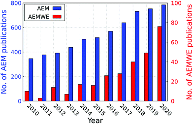 | ||
| Fig. 5 The annual number of publications in the field of AEMs (from Web of Science (access 29.07.2021)). Search terms: “Anion exchange membrane”, “water” and “electrolysis”. | ||
AEM electrolysers work with an alkaline environment at the membrane interface provided by an anion-conducting polymeric membrane, called Hydroxide-Exchange Membrane (HEM), or generically, Anion-Exchange Membrane (AEM). Generally, AEMs are formed by a polymer backbone with anchored cationic groups that confer anion conductivity and selectivity (Fig. 6). The most common relevant backbones cited in the literature used for AEMs are: polysulphone type262–266 poly(ether ketone) type,267–270 poly(ether imide) type,271–273 poly(ether oxadiazole) type,275–277 and poly(phenylene oxide) type,274,278–282 polyphenylene type,283–285 fluorinated type,286–291 polybenzimidazole type,292–298 polyethylene type,299–306 and polystyrene type.264,307–313
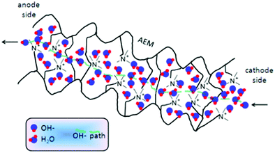 | ||
| Fig. 6 Scheme of hydroxide ion transport through an AEM. Reproduced with permission from ref. 314 Copyright Springer 2014. | ||
A few cationic functional group chemistries have been studied (Fig. 7), most of which involve N-based groups296,315–322 whereby piperidinium323 and spirocyclic280 are currently state-of-the-art. Besides non-N-based cationic groups like phosphonium,269,324–327 phosphatranium,328 S-based functional groups such as sulphonium329–331 and metal-containing anion-conducting groups, such as complexes of ruthenium(II),332,333 Cobaltocenium,334–338 ferrocenium,339 copper(II),340 Nickel(II)341,342 and gold(II)343 have been described (Fig. 7). Alternative anion-conducting groups were also exploited, such as guanidinium.265,328,344–347
These cationic functional groups can be an integral part of the backbone (e.g., polybenzimidazolium-based polymers) or attached to the polymer backbone in different ways (Fig. 8).348 The cationic moieties can also consist of mono-cations or multi-cations.341,349–351 Besides hyper-branched cations (and pendant groups),313,352,353 can also be found.
 | ||
| Fig. 8 Schematic representation for (a) main chain type, (b) comb-shaped, (c) side chain type with multi-cationic head groups, and (d) hyper-branched AEMs. | ||
There are two main synthetic approaches to incorporate the cation functional groups into AEMs for AEMWE (and other electrochemical applications) – the direct polymerisation of cationic monomers and the post-polymerisation functionalisation of the cationic functional groups onto pre-formed polymer backbones.354,355 The most important performance characteristics of AEMs for water electrolysis applications are hydroxide conductivity (ideally, >100 mS cm−1) and water mobility, both of which are directly linked to each other. Zheng et al.297 have summarised conductivity and water uptake (WU) data that have been collected on AEMs submerged in liquid water (e.g., not in contact with water vapor) (Fig. 9).
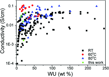 | ||
| Fig. 9 Conductivity as a function of water uptake (WU) from liquid water of AEMs at room temperature (RT, 20–30 °C), 60 °C, and 80 °C. Reproduced with permission from ref. 297. Copyright American Chemical Society 2018. | ||
The conductivity, mechanical properties, and the physical dimensions of an AEM are functions of such water content, making this an important parameter for AEM design for water electrolysers.356Fig. 10a and b summarise hydroxide conductivity and water uptake of highly conducting AEMs reported in the past few years.
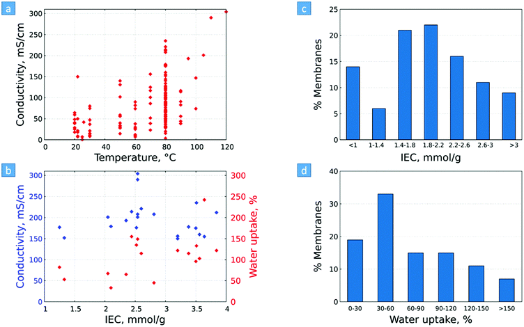 | ||
| Fig. 10 (a) AEM hydroxide conductivity vs. temperature, and (b) hydroxide conductivity and water uptake of selected AEMs (with conductivities ≥150 mS cm−1). (c) Fraction of AEMs at different levels of (c) IEC range and (d) water uptake range. Water uptake values are given in different temperatures. Represented data and the underlying sources are given in Table S1 (ESI†). | ||
Alkaline AEMs (AAEMs) with hydroxide conductivity exceeding 200 mS cm−1 (e.g.,357,358) and as high as ∼300 mS cm−1 working durably at measured at temperatures close, or even above 100 °C were reported,302,303 values which only a few years ago seemed far from possible. These recent data show not only the potential of AEMs to be used in AEMWEs, but also suggest that they can be used in high-temperature AEM fuel cells (HT-AEMFC).303,359,360
High hydroxide conductivity is primarily enabled by a high density of cationic functional groups, e.g., high ion exchange capacity (IEC). Fig. 10c and d show that most of the lately developed AEMs exhibit a mid-range of IEC of 1.4–2.2 mmol g−1, with relatively low water uptake (<60%) making them suitable for their use for AEMWE application.
Similar to what has been observed for the case of AEMFCs,361 the progress achieved in the AEMWE performance is also remarkable; thus the AEMWE cell performance (mostly achieved with PGM-free catalysts) increased from 0.4 (2012) to 5 A cm−2 at 1.8 V reached in 2020 (Fig. 11).
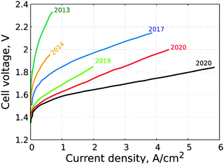 | ||
| Fig. 11 Selected high performance (polarisation curves) of AEMWEs reported in the literature. KOH solutions are fed to the AEMWEs. PGM-catalysts were used in these studies.307,362–368 | ||
Liquid electrolyte (in addition to polymer electrolytes) not only reduces the ohmic resistance of the AEM and the catalyst layer, but also improves the reaction kinetics, increasing in turn, the AEMWE performance369 (Fig. 12).
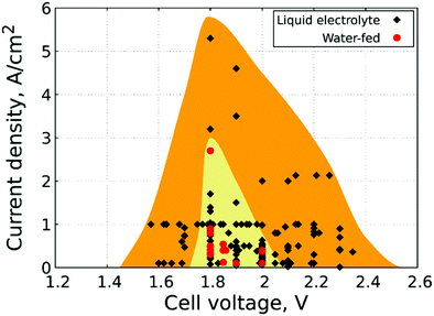 | ||
| Fig. 12 Performance summary of AEMWEs: comparison of current densities achieved at cell voltages in the 1.5–2.4 V range, extracted from different polarisation curves with different feed types. Yellow and orange areas represent AEMWE performance data with (KOH addition) and without liquid electrolyte (pure water). Operating temperature ranges from 22 to 90 °C. Main design parameters, operating conditions and underlying sources are provided in Tables S3 and S4 (ESI†). | ||
Several commercially available AEMs have appeared in recent years.370Fig. 13 compares the performance and performance stability of AEMWEs based on AEMs from both research and industrial groups.
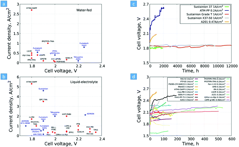 | ||
| Fig. 13 Selected AEMs and their operando performance stability data reported in the literature. AEMs under development (research in universities) are marked in red, and commercially available AEMs are marked in blue, for (a) pure water fed (no liquid electrolyte) and (b) liquid electrolyte. AEMs and their operando performance stability of selected AEMWE cells showing the long-term tests (c) and a zoom in into the 0–600 h range (d). Main design parameters, operating conditions and underlying sources are provided in Tables S3–S5 (ESI†). | ||
Very good performance has been reported with both research and industrial AEMs. Worth noting the outstanding performance of the HTMA-DAPP AEM46 and Sustainion® AEM.371
Despite the numerous reports presenting AEMWE performance data, studies on cell performance stability remain rare: most of the performance stability tests for AEMWE at constant current density showed a substantial reduction in performance in the first 200 h of operation (Fig. 13d), probably owing to chemical degradation of the anion conducting polymers used both as AEMs (and ionomers) at high pH value. Only a few AEMs relatively withstand performance above 1000 h such as Sustainion.368,372 Besides ionomer-catalyst detachment, ionomer poisoning, and catalyst degradation are further issues.373
Mechanical failure of the membrane can contribute to the failure of the entire device; thus, membrane durability is critical to overall system design. Fig. 14 gives an overview of the mechanical properties of selected AEMs. In general, for AEMs to be used in AEMWEs, high Young's modulus, a high tensile strength, and high elongation at break are desired. These properties are usually reported for AEM in their dry halide form at room temperature, which is, unfortunately, not relevant for AEMWE. Higher tensile strength of the catalyst ionomer improves the electrode-membrane adhesion and reduces electrode crack formation, which positively influences the device performance.376 For AEMs, benchmark values of >10 MPa stress at break, >100% elongation at break, and a Young's modulus between 75–400 MPa are proposed as being essential to obtain robust membranes.377
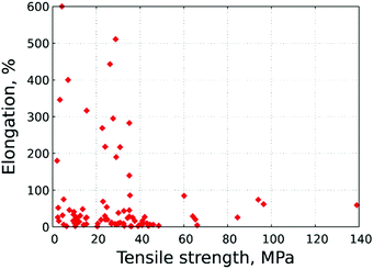 | ||
| Fig. 14 Elongation [%] vs. tensile strength [MPa]. In case there is a range of values, the lower value was considered. Represented data and underlying sources are given in Table S1 (ESI†). | ||
Overcoming degradation caused by the alkaline electrolyte is still challenging. The molecular structure of the anion-conducting polymers (both for AEMs and ionomers in the electrodes) breaks down due to the strong reactivity of the hydroxide ions with the quaternary ammonium (QA) cation leading to a detrimental reduction of the membrane IEC, which, in turn, reduces the anion conductivity (increases cell resistance), causing a rapid decay in the AEMWE performance. Among the different mechanisms of degradation, Hofmann elimination (E2), SN2, N-Ylide formation, ring-opening, deprotonation, SET, and benzyne mechanisms were identified for the ammonium,378 imidazolium,296,320 piperidinium,317,379 carbazolium,321,322 and phosphonium378 groups (Fig. 15).
AEM degradation rate was found to be affected by the concentration of the alkali hydroxide as well as the temperature (Fig. 16). It can be seen that (i) most of the available data is in the 0–2000 h range, significantly lower than the targeted lifetime of the desired AEMWEs; (ii) the degradation rate increases when the temperature increases from 60 to 80 °C or above (Fig. 16). Unfortunately, there are very scarce data published on stability tests longer than 5000 h. Table S1 (ESI†) summarises all details of the stability tests of AEMs.
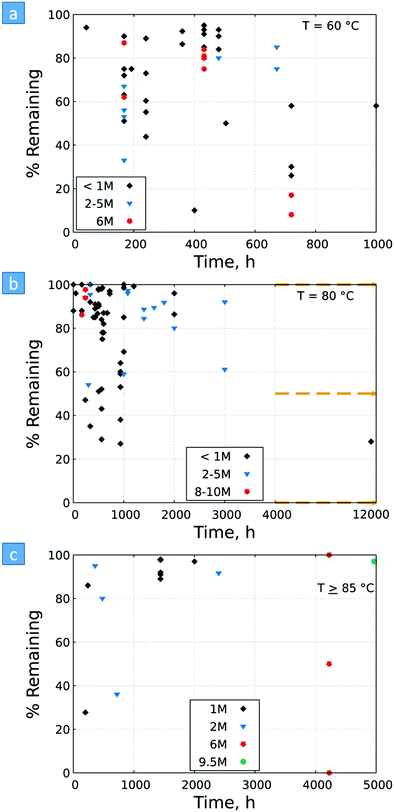 | ||
| Fig. 16 Ex situ alkaline stability data of AEMs. The stability is reported as % QA cation remaining vs. time of stability test, performed in various base concentrations at constant temperatures of (a) 60 °C, (b) 80 °C, and (c) ≥85 °C. Represented data and underlying sources are given in Table S2 (ESI†). | ||
Despite recent improvements in ex situ alkaline stability,296,320,339,380–382 AEM in situ alkaline stability in operando AEMWE is still a major concern, suggesting that maybe more than one single factor should be taken into account.
Ex situ long-term tests do not adequately simulate the liquid-electrolyte-free environment of AEMWEs, yielding false or misleading indications of degradation rates. The combination of two effects explains how an anion-conducting ionomer can be ‘stable’ in alkaline solution ex situ stability tests, but rapidly degrades during operation.383 A new ex situ technique to measure AEM degradation in conditions that mimic an operando cell environment384 as well as new stable cationic groups were recently proposed.296,321,342
Concerning the durability of the backbone, Mohanty et al. showed that aryl ether bonds in the repeating unit have poor chemical stability in alkaline solutions; backbones without aryl ether bonds [e.g., poly(biphenyl alkylene)s and polystyrene block copolymers] remained stable.385 AEM backbone degradation could be triggered by the type of cation functional group, while the cation functional group can be destabilised by the type of backbone used in the AEM.385–389 Müller et al. recently reported a practical and reproducible ex situ method to measure the true alkaline stability of AEMs (interaction between backbone and functional groups)384 that simulates the most severe environment inside an operando AEM-based device (with combined alkaline, temperature, and controlled hydration environment).
AEMs need to be stable towards dissolved oxygen (DO). DO may indeed promote (through ORR in AEMFCs and OER in AEMWEs, respectively) the reactive oxygen species (ROS) formation,390 which in turn, may degrade the AEM polymer.391,392 However current methods cannot reasonably mimic operating AEMWE environment, and new methods need to be developed.
5.3 Proton exchange membrane water electrolyser
As stated earlier PEMWE uses expensive and scarce materials such as iridium (Ir) and platinum (Pt) at the anode and at the cathode respectively, as well as titanium-based materials in the porous transport layer (PTL). The current PGM loading is 2–5 mgIrO2 cm−2 and 1–2 mgPt cm−2 at the anode and cathode respectively, and 100 MW PEMWE would require ca. 50 kg of Ir (assuming a typical Ir loading of 2 mgIr cm−2 active area and operation @ 4 W cm−2). At today's Ir price of US$203 g−1![[thin space (1/6-em)]](https://www.rsc.org/images/entities/char_2009.gif) 393 this would correspond to a staggering US$10.15 million for a 100 MW PEMWE, not to speak from the scarcity of Ir and Pt in the Earth's crust.394
393 this would correspond to a staggering US$10.15 million for a 100 MW PEMWE, not to speak from the scarcity of Ir and Pt in the Earth's crust.394
According to a study from Minke et al.395 current iridium and platinum production rates are estimated at 7–8 and 200 tonnes per annum respectively,37 mined mainly in Canada, Russia, South Africa, United States of America and Zimbabwe, South Africa being the leading producer (70% of the global reserve396).
According to Minke et al.,395 if iridium loading is not significantly reduced and the PGM is not fully recycled (at least 90%), a possible bottleneck in iridium supply is expected as PEMWE installation rates ramp up over a 50 year project (at a linear growth of 2 GW year−1 of installed capacity). As an example, if it is assumed that the 2030 EU target of 40 GW of electrolysers are mainly PEMWE with a current loading of 0.50 gIr kW−1 (0.5 kgIr MW−1 or 500 kgIr GW−1), then 20 tonnes of iridium would be required. Table 6 shows Ir and Pt loading, current and power density and electrode area targets for PEMWE.
| Parameter | 2020 status | 2020 target | 2035 target | Future |
|---|---|---|---|---|
| Ir (mg cm−2) | 2–5 | 1 | 0.2–0.40 | 0.05–0.2 |
| Ir (g kW−1) | <2.5 (0.33/0.5/0.67) | 0.40 | 0.05–0.4 | 0.01–0.4 |
| Pt (mg cm−2) | 1–2 | 1 | 0.5 | 0.05 |
| Pt (g kW−1) | 0.5–1 | 0.5 | 0.25 | 0.1 |
| Current density (A cm−2) | 2 | 2 | 3 | 5 |
| Power density (W cm−2) | 3 | 3 | 8 | 10 |
| Electrode area (m2) | 0.12 | — | — | 0.50 |
Due to price volatility and scarcity of PGM's, one major objective is to drastically reduce their loading by a factor of at least 40, in the case of Ir, and in the long-term to replace them with PGM-free catalysts. The former can be achieved by developing (i) non-carbonaceous high surface area (HSA) supported catalyst, (ii) alloy PGMs with other abundant materials (e.g., other transition metals), or increasing the (iii) catalyst surface area by using better manufacturing methods, and the (iii) catalyst utilisation in membrane electrode assemblies by using better dispersion and deposition techniques.1424
Fig. 17 shows the evolution of platinum and iridium cost (US$ g−1) in the period of 2000–2020. Historically Pt has been more expensive than iridium. However, since 2017, Ir price surpassed that of Pt (since 2015 the price of Ir has increased by ca. 500%; in May 2021, the price of Ir had increased by 20-fold since 2013).
5.4 Solid oxide electrolysis cell
SOEC commonly requires high operating temperatures (≥700 °C), because the yttria-stabilised zirconia (YSZ) electrolyte only displays excellent ionic conductivity at these temperatures. However, during long-term operations, YSZ suffers from thermomechanical and thermochemical issues, particularly under shutdown and temperature ramping conditions, which lead to increased degradation rates and shorter stack and system lifetimes. There are also other issues related to SOEC stack degradation e.g., sealing failure at higher differential pressure, electrode contamination originating from external components (e.g., piping), interconnects and sealing. SOECs are today only deployed at the <1 MW scale, although some current demonstration projects have already reached 1 MW. Deploying SOEC at large scale would require larger SOEC cells than currently used e.g., up from 300 cm2 to over 1000 cm2, which makes them more susceptible to failure.SOEC is mainly made of abundant and low-cost minerals (e.g., Y, Zr, Sr, La, Mn, Ni) and ceramic materials (no rare metals/critical raw minerals are employed). However, SOEC could experience supply risk, as roughly 95% of the supply for all their materials currently originates from China.225 Exact minerals amount per 1 MW cannot be found in the literature but as an example, 1 TW of SOEC would require 1 months and 21 months’ worth of global ZrO2 and Y2O3 production, respectively.
Therefore, the R&D focuses on improving the electrolyte conductivity matching the thermal expansion coefficient of both electrodes, ensuring minimal reactant crossover and optimising chemical and mechanical stability. Decreasing the operating temperatures (≤600 °C) is also an option, opening the way to proton-conducting ceramic electrolysers.
5.5 Proton conducting ceramic electrolyser
Proton conducting ceramic electrolysers (PCCEL) exhibit significant proton conductivity at intermediate temperatures in the range of 300–600 °C397 which was firstly demonstrated in 1981, by Iwahara et al.398 Recently, some research groups399,400 proved that the technology could be scaled up. Like in SOEC, the electrolyte material is crucial. ABO3 perovskites (e.g. Y,Yb-doped-Ba(Ce,Zr)O3−δ) are the most widely-used electrolytes, because they are chemically stable and exhibit high proton conductivity. Examples of perovskites developed include Y and Yb-doped barium zirconate (BZY and BZYb), Y and Yb-doped barium cerate (BCY and BCYb), Y and Yb-doped zirconate-cerate solid solution (BCZY and BCZYb), (iv) Y and Yb-codoped zirconate-cerate solid solution (BCZYYb).401,402In general, PCCELs have similar issues to that of SOECs i.e., problems in cell fabrication and material integrity. As an example, the electrode support structural and compositional homogeneities are critical for large-size cell fabrication; developing novel materials possessing (i) high proton and electronic conductivities, (ii) chemical compatibility and stability with the electrolyte, and (iii) similar thermal expansion coefficients with the electrolyte is the current challenge.397
The overall strategy is to decrease both the ohmic and polarisation resistance component, so as to improve (i) the electrolyte conductivity, (ii) the chemical and mechanical stability, (iii) the understanding of material properties at basic levels (in order to achieve “ideal” microstructures), (iv) the manufacturability (at low-cost), (v) match the thermal expansion coefficient of both electrodes, and (vi) optimise the operating conditions.
In summary for this section, key success factors for water electrolysers are as follows: (i) lower costs, (ii) higher performance, (iii) higher efficiency, (iv) higher durability and (v) lower OPEX. High volumes will definitely decrease the cost of electrolysers and governmental support for R&D in supporting the development of new low-cost highly performing and durable materials is key.
6. Status of PGM-based HER and OER electrocatalysts and their alloys
Due to the importance of water electrolysis and related electrocatalysis, many in-depth and excellent reviews on PGM-based HER and OER electrocatalysts have been recently published.133,403–405 This section will attempt to capture general findings in recent advances in developing strategies to improve HER and OER noble metal-based electrocatalysts.Generally, one of the most critical barriers for electrochemical water splitting is to use high-performance and durable electrocatalytic material that allow both fast HER and OER reaction kinetics and low overpotentials. The choice of HER and OER catalysts in acidic, neutral and alkaline electrolytes is important as the HER and OER reaction kinetics and overpotential will differ. For example, the HER activity in acidic electrolytes is usually 2 to 3 orders of magnitude higher than in alkaline ones, because the water dissociation step is unnecessary in an acidic environment and the high concentration of H+ ions results in faster H–H coupling than at high pH.
6.1 PGM-based HER and their alloys
HER activity is related to hydrogen adsorption (Had) in acidic media, which is composed of either Volmer/Heyrovsky (eqn (6)) or Volmer/Tafel (eqn (5)) steps. In alkaline electrolytes, the Heyrovsky (eqn (4)) and Volmer (eqn (7)) steps occur involving hydroxyl adsorption (OHad), and water dissociation, breaking the strong covalent H–O–H bond. In acidic electrolytes, H3O+ adsorption is much stronger than water adsorption for alkaline conditions. The HER kinetics are highly dependent on various parameters such as the electrode material, the nature of the electrolyte and the crystalline nature and orientation of the electrode (i.e., single-crystal, polycrystalline or amorphous).406 Hydrogen adsorption and desorption on the electrode surface are two successive steps in HER electrocatalysis. However, these two steps compete in nature: a catalyst surface with insufficient bonding strength to hydrogen atoms cannot efficiently adsorb the reactant to initiate the HER; whereas a catalyst surface having too high bonding strength would have difficulty in releasing the product toward the completion of the HER. Therefore, the ideal HER electrocatalysts should have well-balanced hydrogen adsorption and desorption properties.407 This is entirely in line with the Sabatier principle, which states that to have high catalytic activity, the interaction between reactants and catalysts should neither be too strong nor too weak.408 If the interaction is too weak, the catalyst surface will hardly bind the M–H intermediate species, resulting in slow reaction kinetics. If the interaction is too strong, the catalyst active sites will be blocked by intermediate species, leaving no active sites available for new reactant molecules that would continue the reaction.407,409 The Sabatier principle usually yields a “volcano” curve when plotting the activity versus the M–H bonding energy for different metals.98Fig. 3 (Section 2.2) illustrates the relationship between the logarithm of the exchange current density (log(jo)) and the energy of hydride formation (EM–H), which was observed by Trasatti98 in the form of a “volcano” curve:409,410 the HER exchange current density changes by the electrode material, with Pt-group materials on the top of the volcano plot. For alkaline electrolytes, the objective is to increase the M–H2O bond energies to help water adsorption and water dissociation, leading to effective HER kinetics. In alkaline electrolytes, the HER kinetics are sluggish when compared to acidic solutions, and four parameters need to be considered when designing the HER catalysts: (a) water adsorption, (b) water dissociation capability, (c) M–H binding energy, and (d) aqueous OH− on the active sites.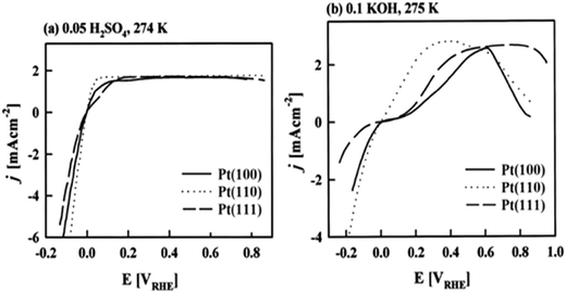 | ||
| Fig. 18 Polarisation curves for hydrogen evolution/oxidation on Pt(hkl), with scan rate of 20 mV s−1, in (a) acid and (b) alkaline media. Reproduced with permission from ref. 409 (copyright MDPI 2020), 410 (copyright American Chemical Society 1997),412 (copyright RSC 1996). | ||
The dependency of the HER rate on the crystallographic orientation of Pt in acidic media is also shown in Table 7.409 For platinum polycrystalline, experiments in acid solutions show that at low overpotentials the recombination reaction, or Tafel step, is rate-determining following the fast-initial discharge reaction or Volmer step. A Tafel slope b ∼30 mV dec−1 is measured at this potential range. As the overpotential is increased, the coverage of absorbed hydrogen atoms approaches saturation. This leads to accelerated atom–atom recombination. As a result, the discharge reaction or Volmer step becomes rate-determining with a measured Tafel slope b ∼ 120 mV dec−1.407 HER is also surface-sensitive on Pt in alkaline solutions. This feature has been shown in Fig. 18. According to Marković et al.,412 Pt(100) exhibits a two-step Tafel slope, starting from 55 mV dec−1 shifting to 150 mV dec−1, Pt(110) exhibits a slope of 75 mV dec−1 that shifts to 140 mV dec−1, and Pt(111) is reported to exhibit a Tafel slope of 140–150 mV dec−1 with no transition in a 0.1 M KOH solution.413
Conway et al.414 illustrated that the Tafel slopes and mechanisms of the HER at Pt in acid and alkaline solutions are rationalised in terms of the observed overpotential-deposited (OPD) H coverage behaviour in relation to a parallel pathway of electrochemical and recombination-controlled desorption steps. The best electrocatalytic activity of Pt electrodes for the HER arises in acid solutions where the nominal extent of measured OPD H coverage is found to correspond to the apparent formation of 8 equivalent monolayers; one possible interpretation of that result is in terms of hydride formation in the near-surface region of Pt. As a result, the OPD M–H adsorption bond can be weakened so that the recombination step with low Tafel slope becomes the favoured desorption step and characterises the kinetics at active Pt electrodes. Based on Conway et al.,414 Tafel slopes of 36–68 mV dec−1 at low overpotentials (η ≤ 0.05) followed by 125 mV dec−1 at high overpotentials ∼η > 0.075 V in a 0.5 M H2SO4 electrolyte for bulk Pt disc electrode have been reported. This indicates the Tafel slope is indeed potential-dependent and, in turn, coverage dependent. Conway et al.414 also showed that the Pt electrode becomes a poorer electrocatalyst for the HER as the cathodic polarisation time increases. In the same paper, the Tafel plot for the same Pt electrode after 30 min cathodic polarisation at ∼η = 0.050 V in 0.5 NaOH is a straight line with a slope of 125 mV dec−1 throughout the potential range measured. According to Conway et al.,414 the decrease of activity of the Pt electrode with time in alkaline solution is appreciably more rapid than in acid solution. Shinagawa et al.413 confirmed that the Tafel slope measured for Pt electrodes in alkaline solutions is around 120 mV dec−1, indicating that the Volmer or the Heyrovsky step is the RDS.
To improve the slow HER kinetics, dual-active electrocatalytic sites i.e., bifunctional HER catalysts need to be engineered allowing better water adsorption/dissociation, hydrogen adsorption/desorption, and OH− desorption. This is often achieved by developing hybrid structures, such as PGM (Pt/Ir/Ru) on Ni(OH)2 surface, PGM (Pt)-decorated Ni3/N nanosheets, NiOx/Pt3Ni interfaces, PGM (Ru)@C2N, Co-decorated PGM (Ru) nanosheets, and PGM (Pd)–CNx composites.
Strncnik et al.417 found that Li+–Ni(OH)2–Pt interface exhibited excellent HER activity in alkaline conditions. It was observed that (i) the edges of the Ni(OH)2 cluster promote water dissociation and the Pt surface adsorbs the hydrogen intermediates for recombining into molecular hydrogen, and (ii) the introduction of Li+ further strengthens the water dissociation ability because of the distributed HO–H bond. The same research group also found that 3D transition metals (Ni, Ti and V) exhibited similar HER activity in both alkaline and acidic electrolytes due to surface oxides aiding water dissociation.418
Another strategy is to dope PGM-based alloy catalyst with N, such as PtNi(N). Xie et al.420 showed that PtNi(N) exhibited superior kinetics when compared to Pt–Ni and Pt/C with Tafel slopes of ca. 29 mV dec−1, ∼η = 0.013 V (@ 10 mA cm−2) and with no potential changes at j = 40 mA cm−2 for 10 hours in 1.0 M KOH. They attributed the excellent water dissociation kinetics to N decreasing the electron density around Ni site, yielding strong interaction between N and Ni.
6.2 PGM-Based OER and their alloys
The OER is the key process that controls the overall efficiency of electrochemical water splitting. This is because the OER is more kinetically sluggish as this reaction is a four-electron transfer process, while the HER needs only two electrons. Binding energy (M–O, M–OH, and M–OOH) is mainly the rudimentary benchmark for OER performance that is usually tuned by electronic and geometric structural “engineering”. Overall, PGM play crucial roles because of their high activities and good selectivity.419 Under acidic environments, the PGM catalytic activities decrease in the order of Ru > Ir > Rh > Pd > Pt > Au, while the structural durability follows the order of Pd > Pt > Rh > Ir > Au > Ru. The most efficient OER catalysts are so far combined Ir and Ru electrocatalysts as it possesses excellent dissolution resistance in acidic conditions. Their oxides such as RuO2 and IrO2, are considered as state-of-the-art electrocatalysts for the OER. To date, many Ir and Ru-based metals, alloys, and oxides have been developed for the OER under acidic environments.419![[double bond, length as m-dash]](https://www.rsc.org/images/entities/char_e001.gif) O), which is a thin oxide layer, participates in the OER, while Pt(II) and/or Pt(IV) oxide layer does neither take part in the acidic nor alkaline OER. In 1991, Damjanovic et al.423 proved that the OER activity of Pt strongly depends on the Pt oxide film thickness. They also confirmed the OER Tafel slopes are always greater than 120 mV dec−1 in acidic solutions at all thicknesses and potentials. Reier et al.424 investigated the OER activity of Pt bulk and Pt nanoparticles in 0.10 M HClO4 and obtained Tafel slopes of 145 mV dec−1 and 210 mV dec−1 for Pt bulk and Pt nanoparticles, respectively, results in excellent agreement with Damjanovic et al.'s findings. The experimentally observed high Tafel-slope illustrates additional contributions from processes with exponential current–potential dependency, probably related to the formation of Pt oxide layers.423,424
O), which is a thin oxide layer, participates in the OER, while Pt(II) and/or Pt(IV) oxide layer does neither take part in the acidic nor alkaline OER. In 1991, Damjanovic et al.423 proved that the OER activity of Pt strongly depends on the Pt oxide film thickness. They also confirmed the OER Tafel slopes are always greater than 120 mV dec−1 in acidic solutions at all thicknesses and potentials. Reier et al.424 investigated the OER activity of Pt bulk and Pt nanoparticles in 0.10 M HClO4 and obtained Tafel slopes of 145 mV dec−1 and 210 mV dec−1 for Pt bulk and Pt nanoparticles, respectively, results in excellent agreement with Damjanovic et al.'s findings. The experimentally observed high Tafel-slope illustrates additional contributions from processes with exponential current–potential dependency, probably related to the formation of Pt oxide layers.423,424
In 1992, Damjanovic et al.425 reported that the OER at Pt in alkaline solutions follows two E–log(j) relationships (Tafel behaviour). At low current densities, the Tafel slope of Pt is close to 60 mV dec−1, and at high current density to 120 mV dec−1. In the high current density region where the Tafel slope is 120 mV dec−1, the reaction rates are strongly affected by the thickness of the anodically formed oxide film during electrode pre-treatment at high current density or at high electrode potentials.424 In contrast, in the low current density region where the slope is 60 mV dec−1, the rates are not affected by the film thickness. In alkaline and acid solutions, an 8–15 Å thick anodic oxide or hydroxide film was found to cover the Pt electrode in the potential region of the OER.424 These oxide films are electronic insulators424–426 and electrons required for the OER are transferred through the films by electron tunnelling process.424 They also observed a decrease with the thickness of the oxide film in the rates in alkaline solutions at high current densities.424 Experimental parameters at high and low current densities based on Damjanovic et al.'s observations are summarised in Table 8.425
Bizzotto et al.427 investigated the OER structure sensitivity on Pt(111) and Pt(100) in 0.10 M HClO4 solution. According to their findings, Pt is structure-sensitive and Pt(100) is significantly more active than Pt(111) towards OER. In their study, the OER activity was evaluated based upon a series of polarisation curve experiments, and the current density values were monitored at a potential of +1.65 V vs. RHE, i.e., j+1.65V. They considered two different potential regions (Fig. 19). In the first potential region ranging from +0.80 V to +1.30 V vs. RHE, j+1.65V was found to be 4 to 5 times larger on Pt(100) than on Pt(111). They estimated the onset potentials of +1.4 V vs. RHE and +1.5 V vs. RHE for Pt(100) and Pt(111), respectively. Tafel slopes of 116 mV dec−1 for Pt(100) and 132 mV dec−1 for Pt(111) were calculated in the potential range of +1.40 to +1.60 V vs. RHE; the higher slope for Pt(111) was related to additional (overlapping) processes to the OER, possibly due to surface oxidation.423–427 They concluded that a potential region exists where the OER is structure sensitive, and no insulating oxide layer is growing. In this potential region, the Pt(100) surface is significantly more active than the Pt(111) surface, although at very high oxidative potentials, i.e. +1.70 V vs. RHE, the structure sensitivity disappears, and the activity of the two single crystals becomes the same (Fig. 19).427
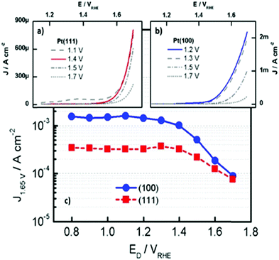 | ||
| Fig. 19 LSV curves of (a) Pt(111), (b) Pt(100) in 0.1 M HClO4 with scan rate of 50 mV s−1. (c) Plot of the current density at +1.65 V vs. RHE (j+1.65V) in the LSV as a function of the applied potential. Reproduced with permission from ref. 427. Copyright Wiley 2019. | ||
In another study by Lopes et al.,428 the relationships between atomic level structure and stability/activity of Pt surface atoms in both acidic (0.1 M HClO4) and alkaline media (0.1 M KOH) was investigated. They found that the degree of stability of Pt(hkl) surfaces (Pt(110) ≪ Pt(100) < Pt(111)) at early stages of oxide formation is proportional to the coordination of surface atoms, as expected from oxophilicity trends. They also investigated functional links between the activity of the OER and the stability of Pt(hkl) surface atoms. According to their studies, the amount of dissolution was directly proportional to the OER activity i.e. the OER activity increased in the order of Pt(100) > Pt(110) > Pt(111) which is the same order of instability.428 These findings were in excellent agreement with those from Bizzotto et al.,427 as the least stable surface is the most active towards the OER.
For example, for acidic media, well-developed structures containing Ir and Ru such as nanosheets, nanotubes and nanoparticles, as well as alloys (containing non-PGMs) and oxides (e.g., as amorphous, perovskite, pyrochlore and hollandite) on carbonaceous/non-carbonaceous substrates have exhibited excellent catalytic activity, catalyst utilisation and durability towards the OER.419,429–440 In general, the catalytic activity towards the OER in acidic electrolytes strongly depend on the electrocatalyst size, surface area, porosity, and the crystal and electronic structure arrangements with other elements to create heterostructures. Chen et al.419 reviewed the current state-of-the art OER catalysts in acidic environments (Fig. 20).
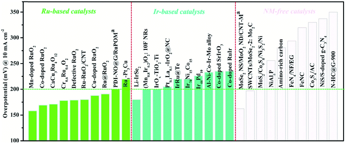 | ||
| Fig. 20 Comparison of OER overpotentials at 10 mA cm−2 for the ten most promising catalysts in each category (Ir-, Ru- and PGM-free based catalysts) in acidic media. (a: the overpotential @ 20 mA cm−2). Reproduced with permission from ref. 419. Copyright Elsevier 2020. | ||
As a matter of fact, the very harsh environment of the OER anode in a PEMWE leaves very little hope to discover catalysts alternative to IrO2 that would be durable and active. Implementing iridium oxide (IrOx) nanoparticles at PEMWE anodes requires developing electron-conductive supports, that are stable in OER conditions, and exhibit high specific surface area and porous structure adapted to gas–liquid flows. Of course, in this seek, carbon can play no role as it will be irremediably oxidised into CO2. That's why, metal oxides are under intense focus since a decade, more specifically substoechiometric (e.g., Magnely-phases: Ti4O7, Ti5O9) or doped metal oxides (e.g., Sb-doped SnO2 or Nb-doped TiO2). Previously used in PEMFC for ORR applications441–444 these metal oxides (e.g., TiO2 and SnO2) have shown some robustness versus oxidation/metal leaching/dissolution. Their Hachille heel however laid in their propensity to passivate at their surface (becoming less electron conductive) and to dissolve/degrade upon incursions to reducing potential. In particular, the doping element was found fairly unstable in operation.
For OER applications, incursions to reducing potentials are avoided, which leaves hope to obtain more stable (doped) metal oxide structures. For example, Claudel et al. evaluated several doped SnO2 aerogels (IrOx/doped SnO2), and assessed their electrocatalytic activity and electrochemical stability towards the OER.34,445 Using a flow cell connected to an inductively-coupled mass spectrometer (FC-ICP-MS), they revealed that the corrosion-resistance of the doping element controls the long-term OER activity of the material. In addition, the doping element concentration in the host SnO2 matrix controls the electron conductivity of the material, hence its propensity to be practically active. The study further demonstrated that Sb-doped SnO2 type supports continuously dissolve in OER operation. On the contrary, Ta-doped or Nb-doped SnO2 supports are more stable under acidic OER conditions, provided their doping concentration is appropriate. Although these studies open a door to nanostructured IrOx OER catalysts (hence to large depreciation of the materials’ cost of a PEMWE MEA), there is still large room for practical improvements. Developing active and durable nanostructured IrOx catalysts for OER in acidic media is therefore still a mandatory research topic if one wants to deploy PEMWE at large scale.
The previous paragraphs showed that PGM-based catalysts are still the norm in PEMWE (and the (almost) only ones that are active and durable in practical acidic operation). In the search for alternative catalyst materials, the present review will focus specifically on catalysts for alkaline systems, for which the available chemistries are far richer (see following sections). Of course, some of these chemistries can find applications in PEMWE cells, as will be specified as well.
7 Status of PGM-free based HER and OER electrocatalysts and their alloys
Due to the low cost and (in most cases) large presence of non-PGM's in the earth's crust, non-PGM-based water-splitting electrocatalysts are of particular interest.71,446–451 The essential groups of non-precious metal-based compound classes (transition metal dioxides, spinels, perovskites, transition metal layered double hydroxide, metal-non-metal-based compounds with the main group elements of groups 3, 4, 5 and 6) are discussed in the following subsections. Water splitting promoted on steel surfaces is considered separately (subsection 7.6). Tables 9–11 summarise the OER key data of some recently-developed PGM-free OER electrocatalysts, HER electrocatalysts respectively.| Catalyst | Substrate | Catalyst loading (mg cm−2) | Electrolyte | η (mV) @ Jgeo = 10 mA cm−2 | Ref. (year) |
|---|---|---|---|---|---|
| GC: glassy carbon; CFP: carbon fiber paper; NF: nickel foam; CNT: carbon nanotube; GP: graphite paper. | |||||
| CoFe LDH | GC | 0.21 | 1 M KOH | 331 (±3) | 823 (2016) |
| Gelled-FeCoW oxyhydroxide | GC | 0.21 | 1 M KOH | 223 (±2) | 823 (2016) |
| Co5Fe3Cr2 (oxy)hydroxide | GC | 0.2 | 1 M KOH | 232 | 895 (2021) |
| CoCuFeMo (oxy)hydroxides | Cu foil | 1 | 1 M KOH | 199 | 896 (2021) |
| Ni6Fe2Cr1 LDH | GC | 0.2 | 1 M KOH | 280 | 897 (2018) |
| Ni3Fe0.5V0.5 | CFP (0.2 cm2) | — | 1 M KOH | 200 | 899 (2018) |
| Ni–Fe–Mo (oxy)hydroxides | NF | 1.6 | 1 M KOH | 238 | 900 (2018) |
| NiFeCe-LDH/CNT | GC | 0.2 | 1 M KOH | 227 | 901 (2018) |
| NiFeMn-LDH | CFP | 0.2 | 1 M KOH | 310 | 902 (2016) |
| NiFe | CFP | 1.67 | 1 M KOH | 248 | 906 (2020) |
| NiFeMo | CFP | 1.67 | 1 M KOH | 201 | 906 (2020) |
| NiFeMoW | CFP | 1.67 | 1 M KOH | 205 | 906 (2020) |
| FeCo | CFP | 1.67 | 1 M KOH | 266 | 906 (2020) |
| FeCoMo | CFP | 1.67 | 1 M KOH | 233 | 906 (2020) |
| FeCoMoW | CFP | 1.67 | 1 M KOH | 212 | 906 (2020) |
| Pororus monolayer NiFe LDH | GP | 0.35 | 1 M KOH | 230 | 846 (2019) |
| NiFe LDH | GC | 0.1 | 1 M KOH | 270 | 894 (2019) |
| NixFe1−xSe2 derived | NF (0.2 cm2) | — | 1 M KOH | 195 | 861 (2016) |
| Ni3FeN | GC | 0.35 | 1 M KOH | 280 | 866 (2016) |
| Fe–Ni–F | GC | 0.714 | 1 M KOH | 225 | 859 (2019) |
| NiFe LDH | GC | 0.1 | 0.1 M KOH | 348 | 1775 (2020) |
| CoFe LDH | GC | 0.1 | 0.1 M KOH | 404 | 1775 (2020) |
| Ni2.5Co0.5Fe LDH | NF | 0.3 | 0.1 M KOH | 275 | 905 (2016) |
| NiFeS | GC | 0.25 | 0.1 M KOH | 286 | 858 (2017) |
| NiFe LDH (pristine) | NF | — | 1 M KOH | 182 | 113 (2019) |
| Aged–NiFe LDH | NF | — | 1 M KOH | 184 | 113 (2019) |
| OER catalyst | Type of activation | Average overpotential at current density (mA cm−2) | Tafel slope (pH) | Faraday efficiency at current density (mA cm−2) | Ref. |
|---|---|---|---|---|---|
| Mild steel | Ex situ inco type 123 paint | 200 mV (100) in 30 wt% KOH at 80 °C | 35–40 mV dec−1 (>14) | — | 1274 |
| AISI 316L | In situ | 500 mV (20) in 5 M LiOH | 40 mV dec−1 (>14) | — | 1277 |
| AISI 316L | Unmodified | 370 mV (10) at pH 14 | 30 mV dec−1 (14) | 96% (10) at pH 14 | 1238 |
| S235 steel | Ex situ | 347 mV (2) at pH 13 | 58.5 mV dec−1 (13) | 67% (2) at pH 13 | 1288 |
| Chem. Oxidation with air/chlorine | 462 mV (1) at pH 7 | 68.7 mV dec−1 | 82% (10) at pH 13 | 1304 | |
| Phosporisation | 326 mV (10) at pH 13 | ||||
| AISI 302 steel | Unmodified | 400 mV (6.3) at pH 14 | 33 mV dec−1 (14) | — | 1275 |
| AISI 304 steel | Ex situ | 500 mV (0.65) at pH 7 | — | — | 1281 |
| Chem. Oxidation with air/chlorine | 260 mV (1.5) at pH 13 | ||||
| AISI 304 steel | Ex situ | 260 mV (10) at pH 14 | 41 mV dec−1 (14) | 366 | |
| Chem. Oxidation with KOH/OCl− | 288 mV (50) at pH 14 | ||||
| AISI 304 steel | Ex situ | 269 mV (10) at pH 13 | 49 mV dec−1 (13) | 75,5% (10) at pH 13 | 1286 |
| Electro-oxidation | 212 mV (12) at pH 14 | ||||
| AISI 304 steel | Ex situ | 504 mV (10) at pH 6.7–7.3 | 138 mV dec−1 | 97% (10) at pH | 1287 |
| Electro-oxidation | 7 | ||||
| AISI 304 steel | Ex situ | 360 mV (100) at pH 14 | 46 mV dec−1 (14) | — | 1298 |
| Etching + electro-oxidation in KRuO4 | |||||
| AISI 316L | Ex situ | 330 mV (100) at pH >14 | 35 mV dec−1 | — | 1454 |
| Electro-oxidation | |||||
| AISI 316L | Ex situ | 270 mV (100) at pH >14 | 40 mV dec−1 (>14) | — | 1289 |
| Electro-oxidation | |||||
| AISI 316L | Ex situ | 290 mV (10) at pH 14 | 35 mV dec−1 (14) | 100% (10) | 1295 |
| Electro/chem-oxidation | |||||
| AISI 302 | Ex situ | 300 mV (10) at pH 14 | 35 mV dec−1 | 1222 | |
| Chem-oxidation | |||||
| AISI 304 | Ex situ | 293 mV (500) at pH 14 | 36 mV dec−1 | 98.5% | 1229 |
| Thermoselenisation | |||||
| AISI 304 mesh | Ex situ | 230 mV (20) at pH 14 | 36 mV dec−1 | — | 1228 |
| Hydrothermal treatment | 173 mV (100) at pH 14 | 65.7 mV dec−1 | 1308 | ||
| Electro-oxidation | |||||
| AISI 316 mesh | Ex situ | 319 mV (100) at pH 14 | 70 mV dec−1 at pH 13 | — | 1307 |
| Electrochem. | |||||
| X20CoCrWMo10-9 | Electro-oxidation | 298 mV (10) at pH 7 | 141 mV dec−1 (7) | 75,6% (10) at pH 7 | 40 |
| Electro-oxidation | 230 mV (10) at pH 13 | 47 mV dec−1 (13) | 83% (5) at pH 7 | 1324 | |
| Oxidation + Li+ inter-calation | 574 mV (10) at pH 1 | 36 mV dec−1 | 95,2% (10) at pH 1 | ||
| 40 mV (10) at pH 7 | 88.7% (10) at pH 7 | ||||
| Ni42 steel | Electro-oxidation | 491 mV (4) at pH 7 | 151 mV dec−1 (7) | 99,4% (2) at pH 7 | 1239 |
| 254 mV (10) at pH 13 | 72 mV dec−1 (13) | 79% (10) at pH 1 | 1327 | ||
| 215 mV (10) at pH 14 | 127 mV dec−1 (1) | ||||
| 445 mV (10) at pH 0 | |||||
| Ni42 steel | Modified in hematite/H2SO4 suspension | 31 mV (30) at pH 0 | 188.7 mV dec−1 (0) | 93% (30) at pH 0 | 1328 |
| HER catalyst | Overpotential (η) in mV HER (j in mA cm−2; pH) | Tafel slope (pH) | Faraday efficiency HER (pH) | Ref. |
|---|---|---|---|---|
| Pt on glassy carbon | 65 (20; 0) | — | 92 (0) | 1257 |
| Commercial Pt/C | 40 (20; 14) | — | — | 910 |
| 50 (100; 14) | ||||
| 100 (15; 9,5) | ||||
| NiO/Ni CNT on Ni foam | 100 (100; 14) | 51 mV dec−1 (14) | — | 910 |
| NiO/Ni core shell NP on CNT | 100 (10; 14) | 82 mV dec−1 (14) | — | 910 |
| 100 (2.5; 9.5) | ||||
| Ni2P | 100 (10; 0) | 81 mV dec−1 (0) | 100 (0) | 1259 |
| Fe | 360 (10; 13) | 105.2 (13) | 911 | |
| NiSe | 185 (50; 14) | 64 mV dec−1 (14) | 100 (14) | 912 |
| CoP | 110 (10; 0) | 64 mV dec−1 (14) | 1260 | |
| 41 mV dec−1 (0) | ||||
| Co2P | 110 (10; 0) | 52 mV dec−1 (14) | 100 (14) | 1260 |
| 45 mV dec−1 (0) | ||||
| Pt–MoS2 | 35 (10; 0) | 54 mV dec−1 (0) | 913 | |
| NiCo2S2 | 305 (100; 14) | 89 mV dec−1 (14) | 914 | |
| 141 mV dec−1 (14) | ||||
| Modified steel Ni42 | 189 (10; 0) | 198 mV dec−1 (7) | 101.8 (13) | 1237 |
| 268.4 (10; 1) | 72 mV dec−1 (13) | |||
| 333 (10; 13) | 118 mV dec−1 (0) | |||
| 299 (10; 14) | 81 mV dec−1 (1) | |||
| 275 (10; 14.6) (at 343.15 K) | ||||
| Steel Ni42 anode in hematite/H2SO4 suspension | 370 (30; 0) | — | 83.1 (0) | 1328 |
| Steel AISI 434 | 315 (10; 14) | 121 mV dec−1 (14) | — | 1266 |
| Sulphurised steel AISI 316 | 136 (10; 14) | 147 mV dec−1 (14) | 100 (14) | 1262 |
| 280 (50; 14) | ||||
| Steel 316L | 340 (1.3; 4) | — | 91.4 (4) | 1249 |
| N,P-Doped AISI 304 steel mesh | 230 (12; 14) | 36 mV dec−1 (14) | 1263 | |
| N-Doped anodised AISI 304 steel mesh | 146 (10; 14) | 60.1 mV dec−1 (14) | 1264 | |
| Fe3C modified AISI 304 | 290 (10; 14) | 38 mV dec−1 (14) | 98 (14) | 1267 |
| Chem.- + electrochem oxidation | 550 (200; 14) | 90. mV dec−1 (14) | 1271 | |
| AISI 304 | 484 (100; 14) | |||
| NiFe LDH (pristine) on NF | 204 (10; 14) | 78.39 mV dec−1 (14) | 113 | |
| Aged–NiFe LDH on NF | 59 (10; 14) | 62.30 mV dec−1 (14) | 113 |
A detailed discussion of possible reaction pathways through which OER occurs when in particular non-PGM-based electrocatalysts are involved would go beyond the scope of this work and we refer instead to the common articles that have been published on the subject.133,452–456,880
A significant technological advance in the development of oxygen evolving electrodes came with H. Beer's 1965 patent on the dimensionally stable anode (DSA), which usually consists of an active metal oxide such as RuO2, thermally decomposed on an inert carrier such as Ti. These electrodes are highly active in supporting electrocatalytic oxidation reactions and are also resistant to chemical and electrochemical degradation.457
7.1 Metal dioxides as OER and HER electrode materials
PbO2, MnO2, MoO2, TiO2 (with restrictions) and SnO2 were investigated as potential water-splitting electrocatalysts. To somehow keep the amount of literature within manageable limits, we will concentrate on MeO2 material in this subsection and hardly consider composite materials containing MeO2458 species.The usual method of forming a lead dioxide containing electrode is to oxidise lead first to PbSO4 and then to PbO2. Oxygen evolution in the lead acid battery occurs as a side reaction on the anode side during charging and as a partial anodic reaction during self-discharge of the positive plate. This is certainly the main reason why the OER properties of PbO2 have been intensively studied for decades.461–465 In one of the first publications dealing with OER on PbO2-based electrodes in sulphuric acid, the OER overpotential to current density relationship was investigated.461 A more detailed investigation of the composition and crystallographic phase of the products formed upon electrochemical oxidation of lead metal in 3.5 M H2SO4 was for the first time reported in 1978 by Pavlov and Rogachev.463 Lead oxidation takes place at the lead|oxide interface yielding tetragonal PbO and then either α-PbO2 or β-PbO2, while the evolution of oxygen (and as we know today not limited to lead metal) takes place at the oxide|solution interface.463,466,467 Oxygen (O2) evolution on PbO2 surfaces follows Tafel behaviour up to current densities of j = 50 mA cm−2 in sulphuric acid with slope values between 90 and 140 mV dec−1,463–465 whereas at higher current densities ozone evolves with a Tafel dependence.464,468–471 First works that report on a reduction of the OER overpotentials determined for PbO2 in H2SO4 were carried out in the late 1980s:466 Sb doped PbO2 significantly reduces the oxygen overvoltage.466 Investigations related to PbO2 concern e.g. detailed kinetic experiments,472,473 elucidation of the electrochemical reactions occurring whilst OER or ozone evolution reaction,474 the influence of ion doping on the ratio of O3/O2 produced,469–471,475 its suitability for wastewater treatment476,477 or the properties as an electrode in the lead-acid battery.478,479 With respect to lead-acid batteries, oxygen evolution is a parasitic reaction that needs to be suppressed rather than accelerated and reducing the OER overpotential is counterproductive.480 Therefore, much effort has been made to increase the overpotential of oxygen evolution of PbO2, which acts as an anode in sulphuric acid.481,482
In addition, experiments on PbO2-based electrode materials aimed rather on lowering the onset potential for ozone formation than for dioxygen formation.475 Deviations from the stoichiometry 1![[thin space (1/6-em)]](https://www.rsc.org/images/entities/char_2009.gif) :
:![[thin space (1/6-em)]](https://www.rsc.org/images/entities/char_2009.gif) 2 in the Pb–O system significantly influence its conductivity and thus also its OER activity. The first publication, which reports specifically on overpotential values at a defined current density for the electrocatalytically initiated OER on PbO2, appeared in 2000.483 Anodes comprise PbO2 doped with Co exhibit an overpotential η of 535 mV for the OER in 1 M NaOH at a current density of j = 100 mA cm−2; the tafel slope amounted to 59 mV dec−1.483 Unfortunately, the study lacks long term polarisation experiments. An enhancement of the OER activity of PbO2 electrodes upon Co doping was later on confirmed by Velichenko et al.475 To the best of the authors' knowledge, the first studies specifically aimed at lowering the OER potential of PbO2-based electrode materials in order to make them a more active oxygen evolving electrode for water electrolysis was not published until 2007.458,484,486,487
2 in the Pb–O system significantly influence its conductivity and thus also its OER activity. The first publication, which reports specifically on overpotential values at a defined current density for the electrocatalytically initiated OER on PbO2, appeared in 2000.483 Anodes comprise PbO2 doped with Co exhibit an overpotential η of 535 mV for the OER in 1 M NaOH at a current density of j = 100 mA cm−2; the tafel slope amounted to 59 mV dec−1.483 Unfortunately, the study lacks long term polarisation experiments. An enhancement of the OER activity of PbO2 electrodes upon Co doping was later on confirmed by Velichenko et al.475 To the best of the authors' knowledge, the first studies specifically aimed at lowering the OER potential of PbO2-based electrode materials in order to make them a more active oxygen evolving electrode for water electrolysis was not published until 2007.458,484,486,487
Abaci et al. and Cao et al. found that the OER activity of PbO2 is enhanced considerably for sub-stoichiometric oxides.485,486 Besides doping with cobalt, doping with Ce or P enables to obtain PbO2 electrodes with increased OER activity.484,487 Phosphorous-doped PbO2 synthesised by co-deposition was investigated by Li et al. The OER activity (η = 615 mV at j = 0.174 mA cm−2) is improved when compared to pure PbO2 generated via a similar approach but, remains substantially lower compared with PbO2 classically-generated via Pb metal electrooxidation.473
A composite material based on titanium used as conductive substrate modified with TiO2 NT/PbO2 exhibited a reasonable low overpotential (η = 630 mV at j = 50 mA cm−2 in 1.53 M H2SO4).488
Since TiO2-NT was created by simple anodisation, the overall process seems straightforward (Fig. 21).
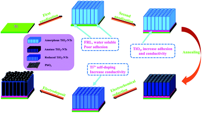 | ||
| Fig. 21 Schematic representation of the generation of Ti/TiO2-NTs/PbO2. Reproduced with permission from ref. 488. Copyright Royal Society of Chemistry 2021. | ||
Thus, all in all, one can say that the overpotentials required to result in reasonable OER-based current densities for lead-based electrode materials are in the range of a few hundred millivolts, which is not on benchmark level.
Alpha MnO2 is regarded as one of the most promising bifunctional catalysts for use in secondary metal–air batteries due to the advantageous OER494,495 and ORR496,497 activity. The unique feature of α-MnO2 is the large cavities (2V2 tunnel) surrounded by edge and corner-linked MnO6 octahedra. The first studies that are dealing with MnO2 anodes for application in aqueous solutions were carried out by Kokhanov and Shembel et al.498,499
Studies that particularly focused on OER on MnO2-coated electrodes were carried out in Japan starting in the middle of the 1970s.500–502 In their first contribution, Morita et al. report on MnO2 electrodes evaluated as oxygen-evolving electrode in 0.5 M H2SO4 and 1 M KOH.500 An active zone comprising a mixture of β-MnO2 and α-MnO2 was achieved on Pt or Ti substrate via thermal decomposition of Mn(NO3)2. The Pt–MnO2 samples turned out to be more active than the Ti-MnO2 ones (η = 650 mV, j = 1 mA cm−2, 0.5 M H2SO4; η = 480 mV, j = 1 mA cm−2, 1 M KOH). Manganese oxide-coated electrodes or electrodes which are coated with mixed oxides containing manganese oxide have found particular interest for seawater electrolysis, since it is known that they somewhat suppress the formation of chlorine.503,504,1853
An active bifunctional electrocatalyst for ORR and OER comprising Mn oxide electrodeposited on glassy carbon was introduced by Gorlin et al.:505 its OER activity (η = 520 mV at j = 10 mA cm−2) in 0.1 M KOH is almost on par with that of Ir or Ru (Fig. 22). XPS results did neither 100% confirm the existence of α-Mn2O3 nor did they unequivocally rule-out the existence of MnO2, though it must be stated that the extreme surface and core of the crystallites may consist of different oxides, especially upon OER.
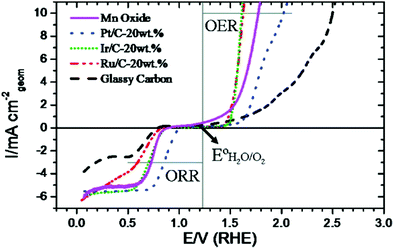 | ||
| Fig. 22 OER activities of the Mn-oxide electrode compared with the ones from Pt, Ir and Ru. Reproduced with permission from ref. 505 Copyright American Chemical Society 2010. | ||
Fekete et al.506 deposited upstream-prepared manganese oxide catalysts using screen-printing, a widely used technique for e.g., circuit boards. The screen-printed films although consisting mostly of the less active pyrolusite phase (β-MnO2) exhibited promising overall OER efficiency (η = 500 mV at j = 10 mA cm−2 in 1.0 M NaOH), suggesting that even materials traditionally considered less active can be activated by the choice of an appropriate deposition method and/or by an appropriate electrochemical activation. In that regard, the work of Moureaux et al. (for the ORR) demonstrated that the activity of nanostructured MnOx/C compounds can be significantly modulated by the nature of the counter cation of the hydroxide-based electrolyte;493 this likely also proceeds for the OER.
α-MnO2 exhibits better OER + ORR properties than β-MnO2 does.495 Selvakumar et al., by hydrothermal procedures, synthesised nano-scaled (wires, tubes, particles) phase-pure α-MnO2.;495 their OER activity based on CV scans is mediocre (η = 570 mV at j = 1 mA cm−2 in 0.1 M KOH) which might be caused by insufficient catalyst loading (0.14 mg cm−2).
MnO2, although in general electrochemically stable, dissolves at high OER overpotentials in acidic media and at low potential values (MnIII is non-negligibly soluble, including in base). Frydendal stabilised MnO2 upon modification with TiO2 or GeO2.507 By DFT, the authors demonstrated that the termination of undercoordinated sites on MnO2 is favourable for guest oxides with lower surface formation energies than MnO2. The calculations exhibit that GeO2 and TiO2 should indeed improve the stability of MnO2.
As mentioned, β-MnO2 shows lower OER activity owing to inaccessibility to the inner Mn centers, in sharp contrast to alpha MnO2. This disadvantage can be overcome via a specific synthesis strategy allowing to achieve highly porous β-MnO2 nanoplates with surface-bound catalytic Mn sites508 (η = 450 mV at j = 10 mA cm−2 in 1.0 M KOH). Zheng et al. investigated the influence of the morphology on the electrocatalytic activity of α-MnO2.509 Two different types of 3D radial a-MnO2 (dandelion- and urchin-like) have been synthesised through a hydrothermal route starting from MnSO4 upon exploitation of two different oxidants (K2S2O8 → dandelion-like; KClO3 → urchin-like)509 (Fig. 23).
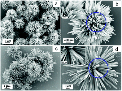 | ||
| Fig. 23 SEM images of dandelion-like- (a and b) and urchin-like α-MnO2 (c and d). Reproduced with permission from ref. 509. Copyright Elsevier 2017. | ||
The MnO2 based OER electrocatalysts listed so far required an overpotential in the 500 mV range to promote anodic water electrolysis with a current density of 10 mA cm−2 in 1 M alkaline. Ye et al. studied transition metal-ion doped MnO2 ultrathin nanosheets electrodeposited on carbon fiber in 2017.510 Transition metal ion doping into MnO2 is capable to increase the conductivity of the MnOx structures511 but also to stabilise the MnIII/MnIV redox shuttle, at least for the ORR.490,512 Anodic co-deposition was exploited to prepare a composite electrode comprising multi (Fe, V, Co, Ni) doped MnO2 nanosheet/carbon fiber paper (Fig. 24): η = 500 mV measured from galvostatic measurements in 1.0 M KOH electrolyte at j = 20 mA cm−2.
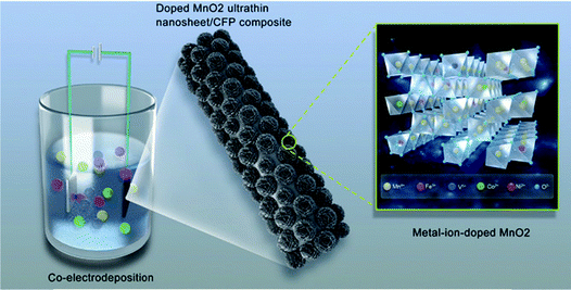 | ||
| Fig. 24 Schematic representation for the preparation of the metal-ion (Fe, V, Co, Ni)-doped MnO2 ultrathin nanosheet/CFP composite. Reproduced with permission from ref. 510, Copyright Wiley 2017. | ||
Tripkovic et al. carried out an in-depth evaluation of (single) doped α-MnO2 in terms of structural stability, catalytic activity and electronic conductivity using DFT calculations.513 To the author's knowledge, the best OER performance determined for MnO2-based electrocatalysts was recently presented by Fang et al.514 Ni doped δ-MnO2 nanosheet array hydrothermally grown on Ni foam (Ni–MnO2/NF) and modified with amorphous mixed-metal (oxy)hydroxide overlayers exhibited a large (active) surface area and high electron conductivity. Short-time treatment of Ni–MnO2/NF with aqueous FeSO4 solution led to the deposition of the mixed metal(oxy)hydroxide layers via galvanic replacement leading to ammo@MnO2 (Fig. 25). The modified OER catalyst reached j = 10 mA cm−2 at only η = 232 mV overpotential in 1 M KOH. However, it is uncertain whether these properties can be maintained in the long-term.
 | ||
| Fig. 25 Process of the surface-guided formation of ammo@MnO2via the galvanic replacement reaction. Reproduced with permission from ref. 514 Copyright Wiley 2017. | ||
Recent theoretical studies provide detailed insights into the requirements that must be met for high OER efficiency of MnO2-based catalysts. The increased OER activity of MnO2 polymorphic OER catalysts is known to be caused by the presence of Mn3+ ions whereby the suppression of the Mn3+ oxidation to Mn4+ by structural constraints was suggested as an important step to enable the accumulation of oxygen holes and the reductive elimination of O2.515In situ electrochemical and X-ray absorption spectroscopic studies revealed that that (i) Mn3+ is kinetically stabilised in tetrahedral centers and (ii) its presence strains the oxide lattice, which leads to a favourable arrangement of oxide-based versus metal-based energy levels, favoring improved OER.516 In general, the overall OER activity (OER-based current per projected area) of MnO2-based material depends on many individual factors like crystal structure,517 Mn517,518 oxidation state, lattice strain,516 the existence of structural fragments (μ-oxo-bridges,815,819 pseudo-cubane fragments519), coordinatively-unsaturated metal cations,520 oxygen vacancies,521 specific surface area,522,523 crystallinity or the electric conductivity of the oxide phase, explaining the richness of the literature about electrochemical properties of MnO2 compounds.
In a sense brought into conversation by nature itself MnO2 is still a promising water splitting electrocatalyst even if it is not one of the current favorites due to the limited performance and durability.
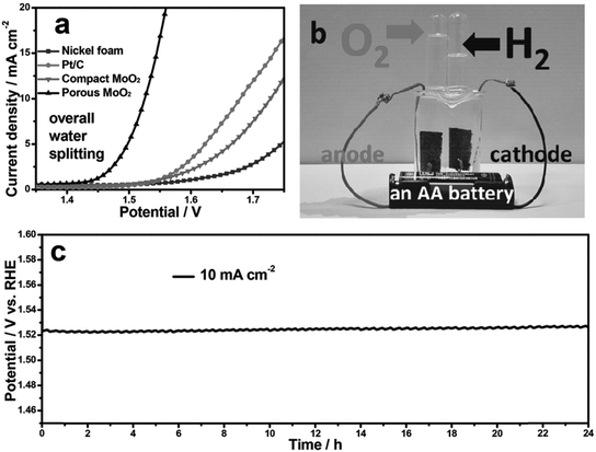 | ||
| Fig. 26 Steady-state polarisation curves for overall water splitting of Ni foam, commercial Pt/C, compact MoO2, and porous MoO2 in a two-electrode configuration. (b) Demonstration of water-splitting device. (c) Chronopotentiometric curve of water electrolysis for porous MoO2. Reproduced with permission from ref. 529 Copyright Wiley 2016. | ||
Oxygen vacancies created in MoO2 by post-treatment using N2H4 solution resulted in good HER (η = 200 mV; j = 10 mA cm−2) and OER (η = 371 mV; j = 85 mA cm−2) properties in 1.0 M KOH.530
Guha et al. synthesised MoO2via reduction of MoO3 upon annealing in hydrogen atmosphere.531 The post-grown MoO2 has OH− occupancy after 7 h annealing in hydrogen (MoO2+OH−) and after 9 h of heat-treatment oxygen vacancies have been created (MoO2−x+OH−). With these defects, MoO2 was durable and active (h = 300 mV; j = 20 mA cm−2; 1.0 M KOH) for OER (Fig. 27).
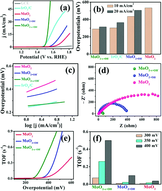 | ||
| Fig. 27 Polarisation curves toward the OER for as-grown MoO2+OH− (7 h case), MoO2–x+OH− (9 h case), commercially available MoO2, and IrO2/C electrocatalysts on GCE in 1 M KOH electrolyte. Reproduced with permission from ref. 531. Copyright American Chemical Society 2020. | ||
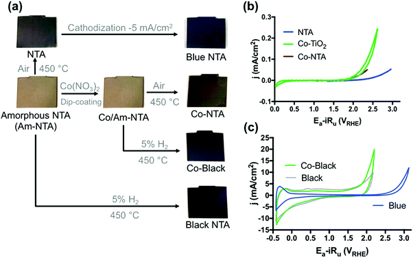 | ||
| Fig. 28 NTA electrode preparation procedures. (b and c) Cyclic voltammograms of NTA electrodes in 100 mM KPi buffer at pH 7.2. Reproduced with permission from ref. 539. Copyright American Chemical Society 2018. | ||
The OER onset potential on pure SnO2 electrodes in aqueous solutions is shifted positive compared to PbO2-based electrodes480 explaining why (pure) SnO2 attracted significantly less attention for water electrolysis.
There are however several contributions that report on SnO2-based composite materials or doped –SnO2 for application in water electrolysis.550,555–559 For instance, Sreekanth et al.559 recently described the synthesis and investigation of SnO2 quantum dots decorated on spinel cobalt ferrite nanoparticles to give SnO2 QDs@CoFe2O4 NPs nanocomposites. In combination with Ni foam, this composite gave an average-active water electrolysis anode for alkaline OER (η = 290 mV; j = 10 mA cm−2; 1.0 M KOH).
However, to the best of the authors' knowledge, water electrolysis with reasonably satisfactory efficiency, which is promoted by a solid (pure) SnO2 electrode or by undoped SnO2 as active species which is only adapted to a conductive carrier, has not yet been described.
7.2 Perovskite-based electrode materials for oxygen and hydrogen evolution
Perovskite is a relatively common mineral from the mineral class of “oxides and hydroxides” with the chemical composition CaTiO3. Due to flexibility in composition (type of metal ions) and electronic structure, the properties of perovskite materials (commonly referred to as ABO3) cover a wide range, explaining their use in various fields.There are already many brilliant reviews that deal exclusively or partially with perovskite oxide-based materials as water-splitting catalysts. Some of these published articles deal with perovskite oxides for photocatalysis purposes560–571 but some of them provide an overview of the knowledge of water electrolysis on perovskite-based materials.24,86,451,572–589 Numerous advanced theoretical and experimental studies have been published, leading to a variety of perovskite-type oxides as potential ORR,590 OER591–597,611 and HER598–600,619 electrocatalysts. Because of the severe oxidative conditions experienced at OER anodes, and the highly-reductive conditions at the HER cathode, metal oxides have traditionally been found more adapted for the OER. This is also reflected in the position of the metal oxides within the Pourbaix diagram (Fig. 29): the number of contributions to perovskite-based OER catalysts far exceeds the number that can be ascribed to HER electrocatalysis. Due to the drastically-increased research output of transition metal-based materials for energy applications, we are unable to give a detailed overview of all known structure-activity relationships or all existing articles that mention perovskite-mediated OER or HER electrocatalysis. We shall therefore limit ourselves to investigations which cover the mile stones and the last stage reached.
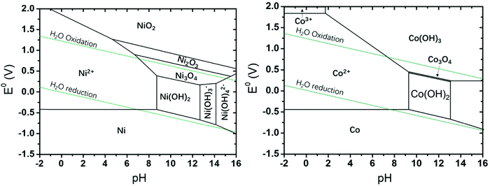 | ||
| Fig. 29 Pourbaix diagrams (potential-pH) calculated for the nickel/water and cobalt/water system. Reproduced with permission from ref. 577. Copyright Wiley 2018. | ||
The first work on perovskite-based OER catalyst dates back to the late 1970s.601 The electrocatalytic properties of oxides of 3d TM have been intensively investigated,602,1309 and it is known that their OER activity depends on the so-called electronic structure.603,604
Various factors of the electronic structure have been used as descriptors for the OER efficiency, including features (energy, filling and width) of the electronic states,605 the M-O coordination state,606,607 covalent part of the TM–O bond,608 and the number of electrons with specific symmetry.609 Such descriptors enable predicting their efficiency. Due to the structural differences of metal oxides, most of the descriptors based on electronic structure are limited to certain specific structural groups. There exist for instance a reliable relation between observed OER activities of perovskites (denoted as ABO3) and the number of e.g., symmetry electrons610,665 of the transition metal (B in ABO3)611 as can be derived from the corresponding volcano plot (Fig. 30).
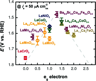 | ||
| Fig. 30 Relation between observed OER activities of perovskites (ABO3) and the number of eg symmetry electrons of the transition metal (B in ABO3). Reproduced with permission from ref. 611. Copyright AAAS 2011. | ||
On both sides of the volcano according to perovskites with too little/too much e.g., orbital occupancy, the too strong/weak interaction with oxygen species is responsible for a lower OER activity. At the top of the volcano, perovskites with eg filling close to unity plot exhibit appropriate binding with reaction intermediates and high OER performance.
Moreover, it was shown that the perovskite family with its chemical tunability of various substituting metals can exhibit excellent catalytic performance.611
In perovskite oxides (ABO3; Fig. 31), the B site is occupied with smaller transition metal ions octahedral (corner shared) surrounded by oxygen (BO6 octaeders). The A position is suitable for larger ions (alkali metal or rare-earth) with 12-fold coordination. On the surface the exposed B sites have BO5 coordination with the vertical oxygen removed, i.e., this geometry would bring the orbital splitting of eg and t2g states to distinct energy levels and this surface can be considered as the active site.612 Synchronised eg electron filling can be disturbed by strong on-site coulomb repulsive interaction between neighbouring eg orbitals which can be up to some extent controlled by introducing high-valence transition metal- or rare earth ions.613 Especially for double perovskite (AA′)B2O6 or A(BB′)O6 the eg orbital filling and thus also the OER properties can be changed in a targeted manner by substitution at certain positions.591,614
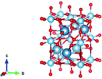 | ||
| Fig. 31 Schematic structure of CaTiO3 perovskite. Reproduced with permission from ref. 580. Copyright Wiley 2019. | ||
Up to now a high number of reasonable- and highly active perovskite-based OER electrocatalysts have been developed.613,615–619
Typically, perovskites are accessible via conventional synthesis methods like for instance high temperature solid state reactions with stoichiometric amounts of solid starting materials synthesis, sol–gel process and high-pressure synthesis. Perovskites synthesised this way are usually characterised by large particle sizes, small surface area (typically below 4 m2 g−1) combined with good intrinsic OER activity.620–625 Suntivic and Shao-Horn611 described a strategy for rationally-designing perovskite-based materials for OER: Ba0.5Sr0.5Co0.8Fe0.2O3−δ (BSCF) catalyses the OER with intrinsic activity that is at least an order of magnitude higher than that of the state-of-the-art iridium oxide catalyst in alkaline media.611 The intrinsic OER activity of the investigated binary-, ternary-, quaternary- and pentanary oxides strictly depends on the occupancy of the 3d electron with an eg symmetry of surface transition metal cations in an oxide leading to a volcano-shaped (electronic) structure-activity relationship.611 In an update Shao-Horn et al. examined the performance of 14 descriptors of the metal-oxygen bond strength using statistical approaches;626 they divided these descriptors into five groups and identified electron occupancy and metal-oxygen covalency as the dominant influences on the OER activity. Durability and performance of perovskites upon OER electrocatalysis have been studied in detail: some of the perovskites are leached by either A or B metal cations and surface amorphisation subject to OER conditions.627,1773,1781
A strategy that aims in improving the overall OER activity is based on increasing the specific surface area and the surface-to-volume ratio by reducing the particle size (down to nm dimension) without compromising the morphology (porosity).628 Nano-scaled perovskites have been accessible by fine adjustment of synthesis conditions of wet chemical routes (sol–gel processes,629–632 hydrothermal procedures.628 Nano-scaled perovskites have been accessible by fine adjustment of synthesis conditions of wet chemical routes (sol–gel processes,629–632 hydrothermal procedures633–641) deposition approaches (chemical precipitation642–652 physical-,653–657 or chemical vapor deposition,658–660 electrodeposition617,661–663), electrospinning,664–667 and template-based approaches.668–679 Nanorods comprising SNCF are also accessible upon a facile electrospinning method (Fig. 32) and showed very good bifunctionality (HER + OER) with respect to water electrolysis (1.68 V cell voltage; j = 10 mA cm−2; 0.1 M KOH).619
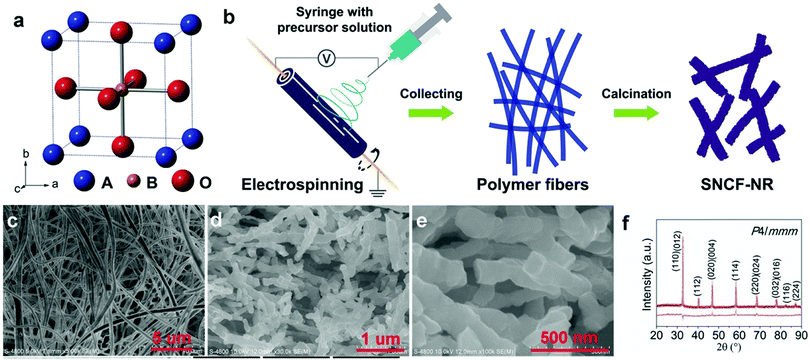 | ||
| Fig. 32 (a) ABO3 perovskite structure. (b) Schematic illustration of the preparation process of SNCF-NR by electrospinning. (c) Scanning electron microscopy (SEM) image of as-spun precursory polymer nanofibers before calcination. (d and e) Low/high-magnification SEM images of SNCF-NR. (f) Refined XRD pattern of SNCF-NR. Observed (purple circles), calculated (red solid line), and differences (orange line, bottom) are presented. Reproduced with permission from ref. 619. Copyright Wiley 2017. | ||
In addition to controlling the particle size of the synthesis product while the synthesis is actually being carried out, top-down approaches to generate small particles using mechanical grinding of bulk materials represent an alternative route to small particles.618,680
Notably; reducing size dimensions to nm scale does not simply increase the surface to volume ratio but can lead to novel physical properties and make nano-sized perovskite different from their bulk counterparts.665,681
Many composite materials developed as potential water-splitting electrocatalysts bear perovskite as the active electrocatalytic phase. Park et al. reported on the synthesis and properties of an electrospun graphene oxide-based composite, baring La0.5Sr0.5Co0.8Fe0.2O3 perovskite nanorods as a catalytically-active phase and exhibiting bifunctional properties for oxygen evolution (η = 570 mV at j = 15 mA cm−2) and oxygen reduction667 (Fig. 33).
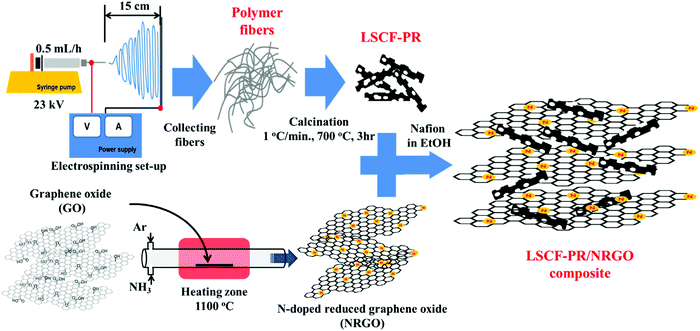 | ||
| Fig. 33 Schematic presentation of the preparation route leading to perovkite-grapheneoxid composite with special morphology. Reproduced with permission from ref. 667. Copyright Elsevier 2014. | ||
Non-noble element-containing perovskites need not shy away from a comparison with highly established and highly-active PGM-containing water splitting electrocatalysts like e.g., IrO2. Chen et al. synthesised nano-scaled oxygen-deficient BaTiO3−x perovskites by sol–gel-based chemistry630 and obtained a reasonable active bifunctional (OER + ORR) electrocatalyst: at relatively low overpotentials (η < 370 mV), it proved more efficient than IrO2 for OER in 0.1 M NaOH.630
In recent years the OER performance of perovskite-based electrode materials was enormously improved.596,682–684 A heterostructured catalyst comprising La0.5Sr0.5CoO3−δ (LSC) perovskite as the OER active part and K+ bonded molybdenum diselenide (K-MoSe2) as the active HER part was very recently shown by Oh et al.684
The LSC/K-MoSe2 system characterises the multidirectional charge transfer phenomenon, with a two-way charge transfer from K to MoSe2 and from LSC to MoSe2 (Fig. 34a and b), which is claimed to be responsible for the good (full-) water electrolysis performance (1.75 V cell voltage; j = 50 mA cm−2; 1 M KOH).
 | ||
| Fig. 34 (a) Schematic of the atomic structure and charge transfer effect for K-MoSe2 and LSC/K-MoSe2. Complementary charge transfer in LSC/K-MoSe2 can modulate the electronic structure of MoSe2, increasing the 1T-MoSe2 ratio in the heterostructure. (b) Charge transfer from K and LSC to MoSe2 in the optimised LSC/K-MoSe2 heterostructure. Reproduced with permission from ref. 684. Copyright Nature Publishing 2021. | ||
Many recently-published papers report on composite materials that contain perovskite as an active part of the OER. For instance, dual-phase perovskite oxide composites comprising Ruddlesden-Popper (RP) perovskite and a La0.33Sr0.67Co0.5Fe0.5O3 single perovskite (SP), each of which self-assembled from perovskite precursors with strongly-interacting interfaces have been synthesised through a cation-deficiency strategy by Xu et al.596 (Fig. 35). The composite with optimised phase composition and structure exhibited competitive overall OER performance (η = 270 mV; j = 10 mA cm−2; 0.1 M KOH).
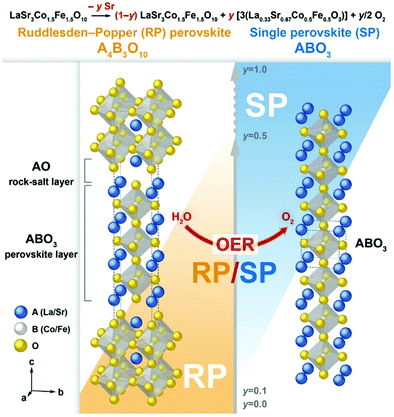 | ||
| Fig. 35 Design of RP/SP composites. Schematic for the RP/SP composites showing RP and SP phase crystal structures. The unit cell of the SP structure is duplicated along the c-axis, to suggest a difference in the material's dimensionality, that is, 2D for RP versus 3D for SP. Reproduced with permission from ref. 596. Copyright Wiley 2021. | ||
7.3 Spinel-based electrode materials for oxygen and hydrogen evolution
Their diverse compositions, electron configurations and valence states, yield a wide range of magnetic-,688–690 optical-691,692–694 electrical-690,695–699 and catalytic-700,701–711 properties.
Many review papers have already been published and deal exclusively712,713,1318 or in part451,575,576,579,581,584,585,588,714–716 with spinel materials for oxygen electrocatalysis.
After briefly working out some general characteristics, the present section will focus on illuminating the publications that can be considered pioneering work both for the development of design principles and for the successful application of these design principles to water oxidation, i.e., work that deals with fascinatingly-active and stable OER electrocatalysts. In addition, very current, promising results will be highlighted.
In an AB2X4 spinel metal A ions (in +2 or +4 oxidation state) occupy the centers of tetrahedral-coordinated positions, metal B ions (in +3 or +2 oxidation state) occupy the centers of octahedral coordinated positions, and the anion (e.g., O2−) is located at the polyhedral vertexes (for normal spinels see Fig. 36a). The tetrahedral spaces are usually smaller than the octahedral ones. Cations with smaller radii preferentially occupy the A sites, while larger cations preferentially occupy the B sites.
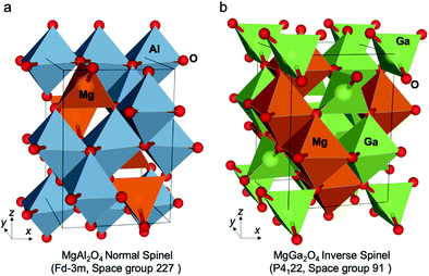 | ||
| Fig. 36 Normal and inverse spinel structures. (a) MgAl2O4 normal and (b) MgGa2O4 inverse ground state atomic configurations. In each case the unit cell is shown by solid black lines. Octahedral and tetrahedral atomic coordination environments are also identified by the coordination polyhedra in each case. Reproduced with permission from ref. 717. Copyright Nature Publishing 2020. | ||
One type of cation may occupy different positions, i.e., tetrahedral and octahedral interstices. Depending on their distribution, spinels are therefore distinguished into three classes: normal, inverse (Fig. 36a and b)717 and complex spinels In normal spinels AB2X4, cations A solely occupy octahedral centers and B tetrahedral centers. This is valid for the “original type of spinel” MgAl2O4. For inverse spinels (B(AB)X4), half of the B cations occupy tetrahedral positions and the remaining half, the octahedral-coordinated centers: MgGa2O4 or NiFe2O4 are typical representatives’ inverse spinels (Fig. 36b). In complex spinels, both sort of metal ions partially occupies both the tetrahedral and octahedral interstices: CuAl2O4 is an example of complex spinel.
Defects are crucial to the spinel's properties, and in particular can significantly increase their catalytic activity.709,718–721
Like perovskites, spinels are an important class of widely available,722 thermodynamically stable,723 relatively cost- and environmental-friendly724 OER electrocatalysts with a well-known good efficiency.709 Spinels are accessible via a number of methods: high-temperature solid-phase synthesis starting from metals, metal oxides, -halides, hydroxides or other salts;725 spray pyrolysis;706 vapor phase methods at lower temperature;726,727 low-temperature methods are also feasible, like solution phase (sol–gel, hydrothermal- or solvothermal-) approaches721,728–732 or wet-deposition-based techniques like e.g. electrodeposition,733 electrospinning,702,734,735 or dip-coating.736
Landon et al.736 reported on the synthesis of spinel-phase based Fe–Ni Oxides with different Ni to Fe ratio by using three different synthesis strategies: evaporation-induced self-assembly, hard templating and dip-coating (sample names = EISA, hard template and Ni mesh, respectively). Regardless of the selected synthesis method, the Ni–Fe oxide catalysts comprising a mixed NiO/NiFe2O4 phase exhibited substantially higher activity than pure oxides, the activity peaking near 10 mol% Fe (Fig. 37a). Reasonable OER activities, although not competitive to recently-developed OER electrocatalysts were shown (η = 440 mV; j = 2 mA cm−2; 1 M KOH; Fig. 37b).
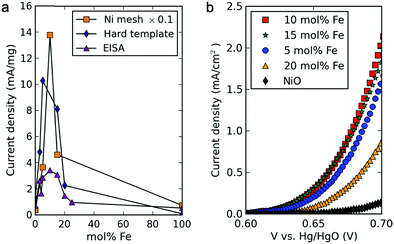 | ||
| Fig. 37 (a) Electrochemical oxygen evolution activity at a fixed overpotential of 360 mV for the varying synthesis methods and compositions of mixed metal oxide electrocatalysts. (b) Geometric area-normalised polarisation (scan rate = 1 mV s−1) data of mixed Ni–Fe oxide catalysts (synthesised by the EISA method) showing the highest activity for 10 mol % Fe oxide. Reproduced with permission from ref. 736 Copyright American Chemical Society 2012. | ||
Crystalline and amorphous films of Co3O4 are accessible via a low-temperature route comprising electrodeposition, e.g., on stainless steel. Koza et al.733 demonstrated convincing overall OER properties of such steel-supported spinel films (η = 400 mV at j = 10 mA cm−2; pH = 13; Fig. 38).
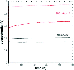 | ||
| Fig. 38 Plot of the overpotential as a function of time at current densities of 10 mA cm−2 (black) and 100 mA cm−2 (red) measured in 1 M KOH for films deposited at 50 °C (dashed lines) and 103 °C (full lines). Reproduced with permission from ref. 733. Copyright American Chemical Society 2020. | ||
The high-temperature solid-state method is useful for large-scale applications, but requires long reaction times.737 In general, all synthesis strategies allow creating defects in spinel structures using specific settings for the respective synthesis method.738–740 All processes discussed so far are also suitable to produce spinel-based nanoparticles,721,730,731,741 whereas vapor-phase processes are particularly suited to synthesise 2d-structured materials.726 In view of their practical application in real water electrolysers, the vast majority of recently published papers in the field of spinel-based water electrocatalysis rely on nanocrystalline systems,727e.g. generated via sol–gel-based methods742–746 as demonstrated by Chakrapani et al. who synthesised uniform and highly dispersed CoV2−xFexO4 (x = 0–2) spinel nanoparticles703 (Fig. 39).
 | ||
| Fig. 39 High-resolution images of spinel-type CoV2–xFexO4 (x = 0–2) nanoparticles: (A) CoFe2O4, (B) CoFeVO4, and (C) CoV2O4. Reproduced with permission from ref. 703. Copyright American Chemical Society 2018. | ||
However, it was found that well-dispersed spinel-structured nanoparticles are also accessible by hydrothermal synthesis using additional surfactants such as ethylenediamine,731 polyvinylpyrrolidone and polyethylene glycol,747 cetyltrimethylammonium bromide or ethanol748 or upon solvothermal routes749 based on e.g. dimethylforamide (DMF),749,750 alcohols102,751 or polyethylenglycole.752 Although even highly faceted nanoparticles can be elaborated via template-free hydrothermal approaches753 the exploitation of hard-672 or soft templates754 still represents the method of choice, when regularly-shaped nanoparticles are desired.
In addition, spinel-based nano-scaled materials are accessible by precipitation- based strategies755–757 or upon an oxidation-precipitation routes.707 The precipitation route might be expanded by templates: transition metal (e.g. Fe) hydroxides can be precipitated in alkaline solution; if Al3+ is simultaneously present in solution Al(OH)3 is precipitated as well, which in principle allows the generation of mesoporous spinel oxides via this hard template-based strategy.758 In general, porous structures are available via the usage of templates754,759 or are accessible by carbonate and oxalate-based precipitants, which will form CO2 upon thermal decomposition.760,761 Small (20 < particle size < 30 nm) but agglomerated cobalt manganese (CoMnO) spinels have been synthesised via a solution-oxidation-precipitation route.707 The tailored generation of cubic and tetragonal-phase material was achieved by simply reordering the addition of Co2+ and Mn2+-containing metal salts in the oxidation/precipitation step (Fig. 40). A hybrid material comprising carbon-supported CoMnO spinel particles synthesised this way exhibied reasonable alkaline OER activity (η = 500 mV; j = 10 mA cm−2, pH 13), though the use of carbon as a conductive additive presents issue in terms of long-term durability (it will irremediably corrode upon OER) and may bias the OER activity measurement as shown by Poux et al. for perovskite oxides during ORR-OER.762
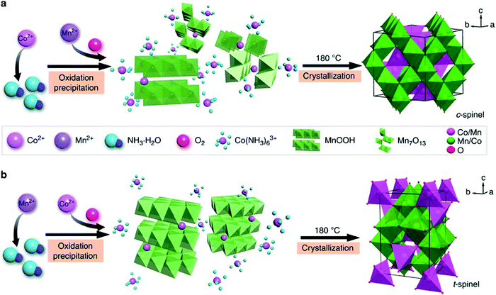 | ||
| Fig. 40 Schematic synthesis of cubic (a) and tetragonal (b) spinel phases, involving two steps of oxidation precipitation and crystallisation. Reproduced with permission from ref. 707. Copyright Nature Publishing 2015. | ||
Cheng et al. introduced a particular synthesis route which takes advantage of oxidation and precipitation to generate a Mn-based spinel precursor, followed by reduction and renewed precipitation (reduction-recrystallisation route).763 Depending on the type of reducer (NaH2PO4 or NaBH4) cubic-phase- (CoMnO-P) or tetragonal-phase CoxMn3−xO4 (CoMnO-B) was obtained (Fig. 41). The OER activity of electrodes prepared with the CoMnO-B-based spinels exhibited reasonable catalytic activity (η = 635 mV at j = 2.5 mA cm−2; pH = 13). DFT calculations provided insight into the capability of the material towards oxygen adsorption, a usual descriptor of ORR activity. OER being the reverse process of the ORR, one predicts that the tetragonal material should provide higher OER activity, in agreement with experimental finding.
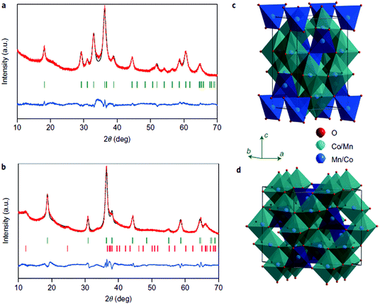 | ||
| Fig. 41 Structural analysis of the synthesised nanocrystalline spinels. (a and b) Rietveld- refined XRD patterns of CoMnO-B (a) and CoMnO-P (b) with experimental data (red dots), calculated profiles (black line), allowed Bragg diffraction positions (vertical bars) and difference curve (blue line). (c and d) Schematic representation of tetragonal (c) and cubic (d) spinels. Reproduced with permission from ref. 763. Copyright Nature Publishing 2015. | ||
Bajdich et al. performed an in-depth evaluation of the activity of spinel-phase cobalt oxides which covers (i) the determination of the stability (under anodic electrode conditions) – and (ii) of the OER activity of selected surfaces in bulk material.711 The investigations resulted in a calculated Pourbaix diagram clearly unmasking β-CoOOH as the OER catalytic active phase for alkaline water electrolysis; its OER activity can be enhanced by surface substitution of Co by Ni (Fig. 42), as experimentally confirmed by the well-known highly-active NiyCo1−yOx.
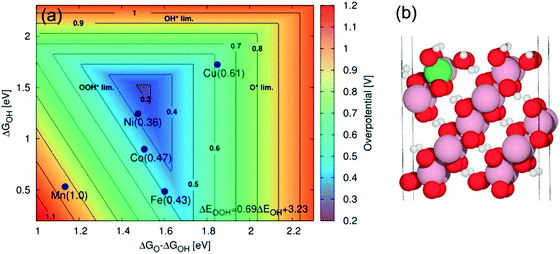 | ||
Fig. 42 (a) 2D map of theoretical overpotentials η for the doped 10![[1 with combining macron]](https://www.rsc.org/images/entities/char_0031_0304.gif) 4 surface of β-CoOOH as function of ΔGO − ΔGOH and ΔGOH. The individual values of η are indicated in brackets. Improvement in activity relative to undoped surface is obtained in the case of Ni with η = 0.36 V and Fe with 0.43 V. Reproduced with permission from ref. 711. Copyright American Chemical Society 2013. 4 surface of β-CoOOH as function of ΔGO − ΔGOH and ΔGOH. The individual values of η are indicated in brackets. Improvement in activity relative to undoped surface is obtained in the case of Ni with η = 0.36 V and Fe with 0.43 V. Reproduced with permission from ref. 711. Copyright American Chemical Society 2013. | ||
As with perovskites,611 descriptors for oxygen electrocatalysis (ORR + OER) have also been developed for spinels.704 For MnCo2O4 species with different electronic structures, the Mn in octahedral centers is identified as the active site. Plotting the ORR/OER activity against the Mn valence state in octahedral site, results in a volcano curve, whose summit locates at the Mn valency of ∼+3. This finding was transferred to other transition-metal-spinels and the active cation eg occupancy in octahedral sites was found the dominating descriptor for spinels ORR/OER activity as well (Fig. 43).
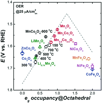 | ||
| Fig. 43 OER activity on various spinels as a function of eg occupancy of the active element at octahedral site. Reproduced with permission from ref. 704. Copyright Wiley 2017. | ||
Several strategies to improve the electrocatalytic properties of spinel electrocatalysts have been considered, including fine-tuning the phase and composition (doping of well-known spinels with metal ions or the combination of spinels with other compounds in a hybrid material strategy)764–771,1324), the introduction of core–shell architectures or general crystal engineering on the nano- or micron-scale.772–778 In one of these exciting works, Bell et al.771 showed how metals like Au, Pt, Pd, Cu, Co can be used to enhance the OER activity of metal oxides (Co3O4 in this study). The electrochemical activity is influenced by the increase in the Co(IV) proportion following the increased oxidation of cobalt oxide by gold (Au has greater electronegativity than Pt or Pd).
Latest efforts aimed in further incrementing the activity of spinel-based OER electrocatalysts.779–785 A nano-scaled oxide hybrid material comprising CoFe2O4 spinel modified by CeO2 (CeO2@CoFe2O4) displayed outstanding OER activity in 1 M KOH: a very low overpotential (η = 213 mV) was enough to reach j = 100 mA cm−2.780 A strategy to increase the number of octahedral OER active sites on the surface of spinel oxides was recently shown by Yue et al.:784 a solid solution comprising MoFe2O4 and CoFe2O4 nanosheets supported on iron foam was synthesised through a hydrothermal route + annealing step (Fig. 44a–c). Additional cation vacancies induced by oxidation of Mo led to cations filling into unoccupied octahedral interstices (cationic misalignment) and to high occupation of octahedral sites, hence to an increased number of OER active sites. The OER activity of the material is convincing, with j = 250 mA cm−2 at E = 1.49 V vs. RHE in 1 M KOH (Fig. 44d).
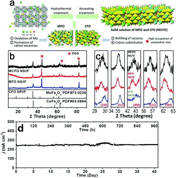 | ||
| Fig. 44 (a) Scheme of synthesis route for MCFO NS/IF. (b and c) XRD patterns of MCFO NS/IF, MFO NS/IF and CFO NP/IF. (d) The chronoamperometric plot of OER on MCFO NS/IF at 1.49 V versus RHE in 1.0 M KOH for 1000 h (25 °C). Reproduced with permission from ref. 784. Copyright Wiley 2021. | ||
10–20 years ago, spinel-based materials were investigated for their photocatalytic properties to promote hydrogen evolution.789,790 Thus, for years, the trend was to use complex spinels for HER electrodes.
Ternary Copper-cobalt-oxide spinels (CuxCo3−xO4) were tested for OER and HER under close-to-real industrial water electrolysis conditions (j = 1 A cm−2; 1.0 M NaOH):787 (i) doping of Co3O4 with copper significantly increased the coating conductivity (maximum at x = 0.3), (ii) accelerated life test showed larger durability of electrodes with x = 0.3 (cathode life = ca. 518 h, versus 190 h for Co3O4).
Zhu et al. reported astonishing HER activity (η = 400 mV; j = 400 mA cm−2) for Co3O4 microtube arrays (Co3O4-MTA) that even outperformed the HER activity of Pt/C.791 However, never before and never again afterwards could Co3O4 be attested to such a high level of activity. One notices that the electrocatalytic HER testing was carried out with a Pt counter-electrode. Obviously, during the HER experiments (continuous cyclic voltammetry scanning for 2000 cycles in aggressive medium: 1 M KOH) Pt from the counter-electrode could have been transferred to the working electrode.1269 So, these experiments should be reproduced/verified, with the nature of the counter-electrode and cell geometry more compatible to best practices.792,1744
All spinel-based materials (M3O4) that proved efficient and stable HER electrodes are altered by doping,789,793–799 or are otherwise modified spinels e.g., hybrid materials that contain pure spinel M3O4 (binary metal oxides)800 besides another e.g., inorganic compound or contain or represent more complex spinels e.g. AB2X4.801–806
Peng et al. studied a spinel-based nanowire electrode system for full water electrolysis.796 NiCo2O4 nanowires, subjected to sulphuration to yield Ni0.33Co0.67S2 nanowires (Fig. 45), showed good alkaline HER performance (η = 100 mV, j = 10 mA cm−2, pH 14). However, upon sulphuration, NiCo2O4 loses its spinel structure and the pyrite structure can be assigned to Ni0.33Co0.67S2.
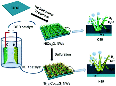 | ||
| Fig. 45 Schematic illustration of the synthesis of NiCo2O4 and Ni0.33Co0.67S2 nanowires, and the utilisation of these homologous Ni–Co based nanowires as OER and HER catalysts for water splitting. Reproduced with permission from ref. 796. Copyright Wiley 2015. | ||
In 2018, complex spinel transition metal oxides (TMO's such as NiCo2O4, CoMn2O4 or NiMn2O4) with a multi–shell hollow structure (necklace-like) were introduced, which were reduced with NaBH4 in aqueous solution (Fig. 46).797 The reduction treatment contributed to their bifunctionality and resulted in reasonable OER alkaline activity (η = 250 mV; j = 10 mA cm−2) and good HER activity (η = 300 mV; j = 200 mA cm−2) combined with good durability in 1 M KOH.
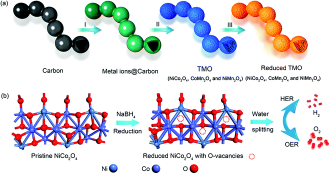 | ||
| Fig. 46 (a) Schematic illustration of the formation process of R-TMO with a necklace-like multishelled hollow structure for water splitting. (I) The absorption of metal ions on the carbon, (II) calcination of the absorbed carbon, and (III) reduction of the TMO to obtain R-TMO with a necklacelike multishelled hollow structure. (b) Schematic illustration of creating oxygen vacancy defects on the surface of NCO after reduction. Reproduced with permission from ref. 797. Copyright American Chemical Society 2018. | ||
Insertion of non-metals like S, P into transition metal-based spinels has become an established strategy to improve their HER electrocatalytic properties.799,800,807–809 Wang et al.799 also demonstrated that P-doping of Co3O4 spinel leads to improved OER activity (η = 260 mV; j = 20 mA cm−2) paired with good HER activity (η = 140 mV; j = 100 mA cm−2) in 1 M KOH.
Muthurasu et al. recently presented a hybrid material comprising Co3O4/MoS2 heterostructure capable to act as anode and cathode in alkaline water electrolysis.800 An OER current density of j = 20 mA cm−2 was obtained at η = 230 mV (HER: η = 205 mV, j = 10 mA cm−2) in 1 M KOH. Williamson et al. recently reported the synthesis of small thiospinel CoNi2S4 nanocrystals with an average size of 4.8–10.7 nm.810
Among spinel-structured NiCo2O4, NiCo2S4 and NiCo2Se4, NiCo2Se4 was found to demonstrate higher oxygen and hydrogen evolution reaction activities (245 mV and 122 mV for j = 10 mA cm2) respectively) compared to those of NiCo2O4 and NiCo2S4.809
Oxygen-defect density is a useful control tool to adjust the electrocatalytic properties that are relevant for water splitting.811 The work covers multi pH water-splitting (alkaline-, neutral and acidic pH) and in addition seawater electrolysis. CoFe2O4 NPs have been generated by precipitation and the as-prepared material (AP-CoFe2O4) was calcinated at 350 °C, 550 °C and 650 °C (samples CoF-1, CoF-2 and CoF-3), which resulted in an increase of the particle size from 8 nm (AP-CoFe2O4), 10 nm, 20 nm and 55 nm (samples CoF-1, CoF-2 and CoF-3; Fig. 47). Sample CoF-2 showed the best intrinsic HER activity (η = 218 mV, j = 10 mA cm−2) for water electrolysis carried out at pH 14 (Fig. 48).
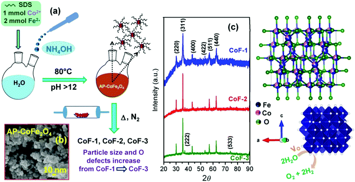 | ||
| Fig. 47 (a) Schematic illustration of the formation of AP-CoFe2O4 through the coprecipitation method followed by thermal treatment under N2 to obtain CoF-1, CoF-2, and CoF-3. (b) Field-emission (FE) SEM image of AP-CoFe2O4. (c) XRD patterns of CoF-1, CoF-2, and CoF-3 NPs. Reproduced with permission from ref. 811. Copyright Wiley 2020. | ||
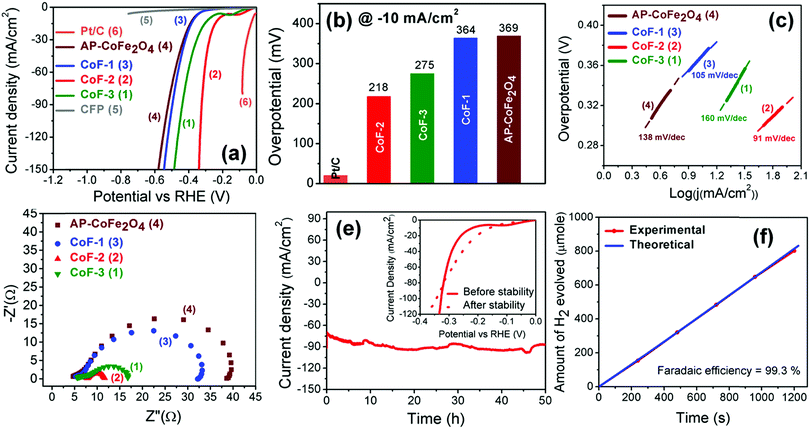 | ||
| Fig. 48 (a) LSV polarisation curves for the HER. (b) Overpotential values reach a current density of 10 mA cm−2. (c) Tafel and (d) Nyquist plots of CoFe2O4 NPs for the HER recorded at 0.4 V versus RHE. (e) Chronoamperometric stability test for CoF-2 performed at 0.35 V versus RHE. Inset shows the LSV polarisation curves before and after stability tests. (f) Experimental and theoretical gas evolution at 0.764 V versus RHE for the HER of CoF-2. Reproduced with permission from ref. 811. Copyright Wiley 2020. | ||
In summary, spinel-based materials are more predestined to act as oxygen-evolving electrodes than as hydrogen-evolving electrodes (a large number of papers are dedicated to spinel-structured materials for the OER), which stems from the intrinsically-larger oxide materials stability in oxidising (OER) than in reducing (HER) conditions. However, recent efforts clearly show that, upon suitable design strategy based on e.g., oxygen vacancy engineering to increase the density of catalytic active sites or doping that may end in better electrical conductivity, highly active and durable spinel structured HER electrocatalysts can also be achieved.
7.4 Transition metal layered double hydroxide OER catalysts for alkaline electrolytes
Late 3d transition metal-based (Ni, Fe, Co, Mn) hydroxides and oxyhydroxides (generally indicated in the following as (oxy)hydroxides) comprise highly active catalysts for the OER in alkaline and neutral pH electrolytes.812 Besides their direct synthesis, surface reconstruction of metal or metal oxide nanoparticles and electrodes in alkaline electrolyte might also result in formation of surface metal oxyhydroxides acting as the OER catalysts (see for example the section related to OER on steels, the surface of which can be close to (oxy)hydroxides). For this reason and the very high activity reported for some of these catalysts (Table 9), they represent an interesting area of research for both fundamental insights into the OER mechanism and practical application as anode catalysts in water electrolysers.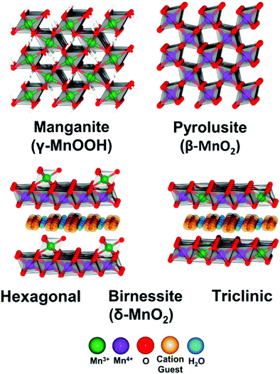 | ||
| Fig. 49 Typical structures of selected Mn-oxides and oxyhydroxides. Reproduced with permission from ref. 820. Copyright ACS 2016. | ||
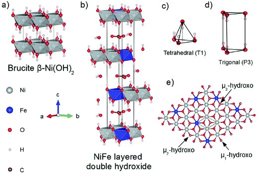 | ||
| Fig. 50 Typical structure of Brucite type Ni(OH)2 and hydrotalcite-like NiFe LDH. Reproduced with permission from ref. 812. Copyright Wiley 2016. | ||
Ternary and multiple metal-based (oxy)hydroxides have also been investigated, where the additional metals have been introduced as dopants into the synthesis of the binary metal LDHs,823 and by systematic compositional studies, for example, by high through-put methods.824,825 Selected examples are discussed in the following section.
A thorough purification of the alkaline electrolyte is important when benchmarking these catalysts, since trace amounts of Fe impurities in the electrolyte significantly enhances the activity of Ni-based and Co-based (oxy)hydroxides significantly.104,828 Consequently, Fe-activated Ni hydroxide catalysts and, in general, NiFe (oxy)hydroxides are among the most active OER electrocatalysts at alkaline pH (Fig. 51a). CoFe oxyhydroxides are also more active than Co oxyhydroxides.103 To evaluate the catalytic activity of transition metal (oxy)hydroxides the OER overpotentials are typically compared at a fixed geometric current density, i.e., j = 10 mA cm−2 (different types of intrinsic activity metrics were proposed in the literature (see Section 7.2). However, determining the intrinsic activity for these catalysts is challenging, since the nature of the active sites is often unknown, and their surface concentration is also difficult to estimate due to rough surface morphologies. This affects the calculation of turn over frequencies (TOF). Also, the evaluation of the electrochemical surface area (ECSA) to calculate surface specific activities must be performed with care, since the electrical conductivity of LDHs changes with the applied potentials829 resulting in a narrow or non-existing potential window that is free of faradaic current in the conductive regime. This limits the range of potentials where certain electrochemical techniques can be applied, such as the ones based on cyclic voltammetry or electrochemical impedance spectroscopy (EIS). Furthermore, metal oxidation peaks in cyclic voltammograms often overlap with the OER faradaic current and model catalysts with smooth planar surfaces for the conversion of the calculated values, i.e., capacitances, in the unit of an area are not always available.830 Recently, a method to calculate the ECSA based on the capacitance of the adsorbed OER intermediates (Ca), instead of the more commonly used double layer capacitance, was proposed for a series of transition metal based LDH catalysts.831Ca was calculated by EIS at 1.6 VRHE, and normalised by the specific unit area capacitance that was obtained from a smooth Ni(OH)2 surface from ref. 832. This method surpasses most of the mentioned limitations, providing surface-based intrinsic activities and calls for new experiments that provide specific unit area capacitances for the different LDHs. The general intrinsic activity trend was NiFe LDH > CoFe LDH > Fe-free Co-containing catalysts > Fe-Co-free Ni-based catalysts (Fig. 51b).
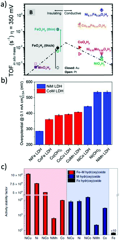 | ||
| Fig. 51 Transition metal (oxy)hydroxides and LDHs OER performance trends. (a) Activity trend as effective turnover frequencies (TOF) at overpotential η = 350 mV and based on the total mass of the electrodeposited catalyst films calculated from quartz crystal microbalance measurements and ordered based on the atomic number of the host/primary metal cation. Electrolyte: 1 M KOH. Reproduced from ref. 826. Copyright American Chemical Society 2015. (b) Intrinsic activity trend as OER overpotentials at ECSA-normalised current densities of 0.1 mA cm−2ECSA for crystalline transition metal LDHs. Electrolyte: 0.1 M KOH. Reproduced from ref. 831. Copyright Wiley 2021. (c) Activity stability factor (ASF) trend for Fe containing (red bars) and Fe-free (blue bars) transition metal hydroxy oxide clusters. The Fe containing catalysts were obtained by adding Fe nitrate to the 0.1 M KOH electrolyte. Reproduced with permission from ref. 827. Nature Publishing 2020. | ||
In contrast to the activity, these catalysts stability has been less systematically investigated. The most commonly performed stability tests range from short term stability tests (2 hours) at low current densities of (j = 10 mA cm−2)833 mostly used for preliminary screening, to galvanostatic stability tests over longer time, for example hundreds of hours,834,835 as well as at higher current densities (>100 mA cm−2).835,836 Chronoamperometry measurements, for example at the applied cell potential of 1.6 V,835 have been also used as well as protocols simulating the natural day-night light cycle,835 and stability tests at higher temperatures (>80 °C)837 and high KOH concentration (>1 M).835,836 Most of these studies were performed on NiFe (oxy)hydroxide catalysts. At room temperature, stability tests of NiFe (oxy)hydroxide catalysts generally show very promising results with the stability of dozens of hours, and in some cases even more. However, stability tests must be ran also at operation-relevant temperatures for alkaline electrolysers, i.e., ∼80 °C.838 Recently, Chung et al. extended to late 3d transition metal (oxy)hydroxide catalysts a previously proposed metrics called activity-stability factor (ASF)839 that takes into account both activity and stability (Fig. 51c).827 This was obtained by the evaluation of both the OER activity, in terms of current densities at 1.7 V vs. RHE, and the stability, as the rates of metal dissolution. Finally, the ASF was calculated as activity/stability ratio and expressed the amount of O2 that is produced per dissolved active site. Ni-based and Co-based (oxy)hydroxide clusters that incorporated Fe, which were prepared by adding Fe nitrate to the electrolytes, showed higher ASF than their Fe-free analogues. In these Fe-containing catalysts the authors found higher Fe dissolution than the metal host dissolution, suggesting that the poor activity retention in Fe-free electrolytes was related to the dissolution of Fe active sites. Finally, they suggested that Fe dissolution and electrochemical re-deposition yields dynamically stable Fe active sites, providing a strategy for designing better catalysts.
In the following sections, we will focus mostly on Ni-based (NiFe) LDH and (oxy)hydroxide catalysts, which have been the most investigated in alkaline electrolytes, and on their activity (for their stability we refer to the discussion in this section). Later, selected results obtained with the other transition metal LDH and (oxy)hydroxide catalysts will be summarised.
In particular, the electrochemical conditioning in alkaline electrolyte that leads to activation of an NiFe oxyhydroxide surface allowed the investigations of NiFe-based pre-catalysts with different electrical conductivity and structural properties, such as metal alloys,850,1752 phosphides,855 sulphides,856–858 (oxy)fluoride859,860 and selenides.861,862 A detailed review of these materials can be found in ref. 863. In addition, NiFe-based nitrides have also been investigated.864–866 Furthermore, composite and hybrid catalyst materials employing NiFe (oxy)hydroxide and nanocarbon materials were also prepared to achieve better active sites utilisation and improve the electrical conductivity.844,867–871 Besides carbon, different supports have also been investigated, and gold has been found to affect the intrinsic activity of NiFe (oxy)hydroxide thin films.104,851,872–875 However, the authors note that carbon cannot be considered a stable support for OER operation, according to its unavoidable corrosion in such alkaline oxidising conditions, in particular in presence of metal (-oxide) catalysts.876,877,1361,1363–1365,1367
The OER activity of NiFe (oxy)hydroxides was found to depend on many parameters, including Fe content, electrolyte pH, cations, and structural disorder, among others. Fe incorporation in Ni-based (oxy)hydroxides catalysts821,878,879,1244,1771 decreases in the overpotentials by 200–300 mV with respect to Fe-free Ni(OH)2 and generally a maximum in activity is reached for 10–50% Fe metal content.812 Fe metal sites at the high index surfaces of Fe doped γ-NiOOH have been suggested as the OER active sites by a combination of operando X-ray absorption spectroscopy (XAS) and DFT+U calculations (Fig. 52a).878 The classical OER mechanism where the adsorbed OH*, O*, OOH*, intermediates form on top of the active site was considered.127,880 Several works and results supported this hypothesis,842,851 while others considered alternative mechanisms and sites.881–883 For example, the electronic effect of Fe atoms on Ni sites, which acted as superior Lewis acid and promoted the formation of tetravalent Ni, was discussed by Li et al.884 In their proposed mechanism, the increased population of Ni4+ leads to greater Ni–O covalency, and thus greater oxyl character by Ni(III)–O˙ resonant contribution, with the oxyl radical finally promoting O–O formation. Drevon et al. performed in situ XAS at the oxygen K-edge and their results are consistent with the presence of an electron deficient oxygen site prior to O–O formation.885 This observation might be related to the superoxo species (NiOO−) or “negatively charged oxygen” ligands that were previously proposed to participate to the OER mechanism on NiFe and Ni (oxy)hydroxide catalysts.78,110,886 Recently, DFT calculations by Dionigi and Zeng et al. confirmed that Fe sites are more active than Ni sites, but revealed that O-bridged Fe–Ni reaction centers and the synergy between the two metals stabilise OER intermediates that are unfavourable on single Fe sites or on O-bridged metal-metal sites of the same metal (Fig. 52b).1775 Therefore, they proposed that the bridging oxygen between Ni and Fe atoms in the γ-phase of NiFe LDH is the active sites. The OER mechanism starts from the deprotonation of that bridging O site, which is saturated by H under OER conditions according to the calculated surface phase diagrams and follows a Mars-van-Krevelen mechanism involving the surface lattice oxygen. With the O2 release, a vacancy is formed that will be refilled in the next cycle by OH− from the electrolyte.
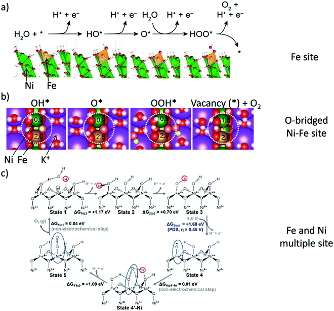 | ||
Fig. 52 NiFe (oxy)hydroxide active site and OER mechanism by DFT calculations. (a) Proposed OER pathway involving the HO*, O* and HOO* intermediates and with a Fe atom site that was substituted in the (01![[1 with combining macron]](https://www.rsc.org/images/entities/char_0031_0304.gif) 2) surface of γ-NiOOH as the active site. Reproduced with permission from ref. 878. American Chemical Society. (b) A second proposed OER mechanism and intermediates on the H-saturated O-bridged Ni–Fe site as active site at the (01–10) surface of γ-NiFe LDH. The reaction centers are highlighted by large dotted white circles, the vacancy by a small pink dashed circle. The magnetic moments of Ni and Fe during OER are also given. Reproduced with permission from ref. 1775. Copyright Nature Publishing 2020. (c) A third example of proposed mechanism for OER on Ni1−xFexOOH catalyst. Blue ovals highlight the synergistic role of Ni and Fe sites in forming key reaction intermediates. Reproduced with permission from ref. 888. Copyright American Chemical Society 2018. 2) surface of γ-NiOOH as the active site. Reproduced with permission from ref. 878. American Chemical Society. (b) A second proposed OER mechanism and intermediates on the H-saturated O-bridged Ni–Fe site as active site at the (01–10) surface of γ-NiFe LDH. The reaction centers are highlighted by large dotted white circles, the vacancy by a small pink dashed circle. The magnetic moments of Ni and Fe during OER are also given. Reproduced with permission from ref. 1775. Copyright Nature Publishing 2020. (c) A third example of proposed mechanism for OER on Ni1−xFexOOH catalyst. Blue ovals highlight the synergistic role of Ni and Fe sites in forming key reaction intermediates. Reproduced with permission from ref. 888. Copyright American Chemical Society 2018. | ||
The hypothesis of lattice oxygen involvement into the OER mechanism (LOER) was also investigated by isotope labelling experiments.847,850,887 Roy et al. investigated electrochemically activated NiFe alloy nanoparticles using isotope-labelling experiments with an electrochemical mass spectrometry setup and concluded that the OER is only limited to the near-surface region and does not proceed via lattice oxygen exchange.850 Following a different experimental approach, Lee et al. performed 18O-labeling experiments in combination with in situ Raman spectroscopy:847 lattice oxygen participation in the OER for Fe-free NiOOH was proposed, probably via formation of NiOO− intermediates. However, while oxygen exchange was observed in ultrathin NiFe LDH if the catalyst was in the reduced state (Ni atoms in Ni2+ state), the experiments with oxidised ultrathin NiFe LDH catalyst agreed with Roy et al.850 Recently, LOER was directly confirmed for Fe-free Ni(OH)2/NiOOH by Ferreira et al. by using a novel differential electrochemical mass spectrometry (DEMS) cell interface and isotope labelling experiments.887 Furthermore, the authors observed evidences of LOER also for NiFe LDH, supporting previous hypothesis of a Mars-Van-Krevelen mechanism.850,1775 Differences in the literature regarding the detection of LOER on NiFe oxyhydroxide catalysts may be caused by rapid ligand exchange prior to LOER detection, different pre-treatment protocols or arising from structural differences among the investigated catalysts.
The synergy between Ni and Fe as the origin of the enhanced activity was also proposed by Goddard and co-workers.111,888 Their proposed mechanism involved multiple sites and their DFT calculations revealed that the formation of a key O˙ intermediate is stabilised on the high spin d4 Fe4+ site, while the subsequent O–O coupling is catalysed on low spin d6 Ni4+ site (Fig. 52c). The deprotonation of the OOH adsorbed on Ni4+ forms O2− on the Ni4+ site, in agreement with previous experimental findings that suggested a NiOO− species78 before the final release of O2. Despite no universally accepted mechanism is agreed on, these works highlight the importance of Fe and especially its interaction and synergy with Ni, as the origin of the enhanced (and stabilised) OER activity of NiFe (oxy)hydroxides.
Another important factor affecting the activity of NiFe oxyhydroxides is the pH of the electrolyte, as revealed by the super-Nernstian behaviour on the NHE scale.844,889,1864
Electrolyte alkaline cations have also been observed to have an effect on the activity of NiFe oxyhydroxide catalysts, following generally the trends of increasing activity from smaller to larger cations, i.e. Cs+ > Na+ ≈ K+ > Li+,79,889 and K+ ≈ Mg2+ ≥ Na+ ≫ Ca2+.890 Such a trend was suggested to result from intrinsic effects due to modification of the adsorption energies of OER intermediates (*OH, *O, *OOH) on Ni(Fe)OOH,890 and to better stabilisation by larger cations of the superoxo OER intermediate (NiOO−) in Fe-free NiOOH.79 Recently, it has been highlighted that intrinsic cation effects should be carefully decoupled from indirect pH effects:889 at parity of cation concentration, the electrolyte pH increases from small to large alkali metal cations in the order LiOH < NaOH < KOH< RbOH < CsOH. After taking into account pH differences, the intrinsic promoting effect of alkaline cations on the activity was found to be minor, when compared to Fe substitution and pH differences,889 but still revealed that a lower activity is obtained with Li+ in respect, for example, to K+, as also previously observed with 316L activated steel, which presents a near similar surface structure as NiFe LDHs and (oxy)hydroxides.1277
Besides cations, anions have also been the subject of experimental and theoretical studies. Many intercalated anions have been shown to quickly exchange to carbonate when the electrolyte is in equilibrium with ambient conditions.891 However, by carefully employing carbonate-free electrolyte, Hunter et al. found that the activity correlates with the pKa of the conjugate acid of the interlayer anions.891 Zhou et al. showed by DFT calculations that the intercalated anions affect the electronic structure of surface metal atoms, which may lead to higher activity.892
The impact of structural disorder on the activity was also investigated. Fe incorporation in NiOOH was found to lead to higher structural disorder.893,1279 From XAS observation, Smith et al. reported structural distortions on the oxidised form of a series of NiFe oxyhydroxide catalysts that were induced by Fe incorporation854 and proposed the introduction of localised structural distortions as strategy to improve the Ni-based (oxy)hydroxide activity. Lattice distortion and introduction of tensile strain into NiFe-LDH was also obtained by Zhou et al. by ball milling and correlated with improved performance.894 Recently, Lee et al. found a volcano-type correlation with the structural disorder and the TOF of Fe sites as a function of Fe content.893 Therefore, they suggested that structural disorder should be optimised to improve NiFe LDH activity.
For CoFe (oxy)hydroxides, Zhang et al. reported a CoFeW oxyhydroxide catalyst in which tungsten modulated the electronic structure of the catalyst, resulting in enhanced activity.823 Cr was also reported to enhance the activity of CoFe (oxy)hydroxides, and Chen et al. found an optimal composition of Co5Fe3Cr2 (oxy)hydroxide, with Cr affecting the Co electronic structure, resulting in higher TOF.895 Among Co-based quaternary metal oxyhydroxides, Zhang et al. reported ultrathin CoCuFeMo (oxy)hydroxides nanosheets with enhanced OER performance.896
Cr addition was also investigated for NiFe (oxy)hydroxides:897,898 electrodeposited NiFeCr (oxy)hydroxide thin film catalyst where Cr was found to dissolve and re-deposit on the surface898 showed higher activity than the bimetallic NiFe oxyhydroxide catalyst and the authors suggested Cr6+ sites as the active sites, which was supported by DFT calculations. Iron and vanadium co-doped nickel (oxy)hydroxide was reported by Jiang et al.:899 the metal composition of Ni3Fe0.5V0.5 resulting in highest activity and the authors suggested combining DFT and XAS that the V site with neighbouring Fe atoms is the active site. Other investigated metal additions to NiFe oxyhydroxides include Mo,900 Ce,901 and Mn.902 Chung et al. proposed Fe–NiCu oxyhydroxide as a new promising catalyst, showing higher activity than the Cu-free Fe–Ni catalyst and a remarkable stability, leading to the highest ASF among the investigated catalysts.827
Many researchers also studied the possible synergies arising from Ni–Co–Fe compositions, and the results generally pointed to a small enhancement versus binary NiFe (oxy)hydroxide catalysts, which suggested a minor but positive synergistic effect.903–905,1752,1794 High-throughput mapping methods screening generally metal oxides, highlighted metal combinations such as Ni–Fe–Co–Ce,824 Ni–Fe–Al, Ni–Fe–Ga, and Ni–Fe–Cr,825 which, on the basis of possible surface reconstruction, are also promising for metal (oxy)hydroxides.
Zhang et al. performed DFT calculations on both NiFeX and NiCoX series, where X (X = W, Mo, Nb, Ta, Re and MoW) consisted in a high-valence transition-metal dopant and acted as modulator of the electronic structure:906 for both NiFeX and CoFeX oxyhydroxides, the presence of Mo and W significantly enhances the activity. Furthermore, the quaternary CoFeMoW oxyhydroxide is expected to be slightly more active than the ternary CoFeW and CoFeMo based catalysts, while the same is not expected for the NiFe-based series. Experiments in 1.0 M KOH agreed with the calculation results. The stability was high: the NiFeMo oxyhydroxide catalyst was stable in an electrolyser anode that delivered 300 mA cm−2 at ∼1.7 V consistently over 120 h in 30% KOH electrolyte at 85 °C.
Finally, it is worth to mention that NiFe LDH when employed as HER/OER bifunctional catalyst is able to reach very low overpotentials.113,907 For this catalyst a dynamical self-optimization mechanism was reported, which involved an increased crystallinity at the cathode during HER, resulting in a significantly lower HER overpotential than the pristine catalyst.113 Further bifunctional electrocatalysts will be discussed in Section 8.3. Fig. 53 displays a comparison of the OER activity determined in 1 M KOH of commercially available OER materials, i.e., currently used in electrolyzers (RuO2, IrO2, stainless steels) together with the corresponding data of the materials discussed in Section 7.4.
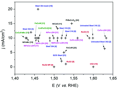 | ||
| Fig. 53 A comparison of the OER activity of commercially available OER electrode materials like RuO2, IrO2 (highlighted in red), steel based OER materials (highlighted in blue), transition metal layered double hydroxides (pink), oxyhydroxides (black) and other state of the art OER electrocatalysts (green). The displayed OER materials are unmodified AISI 316 steel (1),1238 unmodified AISI 302 steel (2),1275ex situ modified steel 304 (3),1286ex situ modified steel 304 (4),370ex situ modified steel 316 (5),1295ex situ modified steel 302 (6),1222 RuO2 (7),908 RuO2 (8),908 RuO2 nanoparticles (9),26 IrO2908 (10), NiCeO on gold (11),909 CoFe LDH (12),823 gelled FeCoW oxyhydroxide (13),823 Co5Fe3Cr2 (oxy)hydroxide (14),895 CoCuFeMo(oxy)hydroxide (15),896 Ni6Fe2Cr LDH (16),897 NiFeCe LDH (17),901ex situ modified steel 304 mesh (18),1228 NiFeMo (19),906 Porous monolayer NiFe LDH (20),846 NiFe LDH (21),894 CoFe LDH (22),1775ex situ modified steel S235 (23),1288 PrBaCoO3 (24),591 FeCoW oxyhydroxide (25).823 | ||
To summarise this section, typical metals introduced to boost the catalytic performance of binary NiFe and CoFe (oxy)hydroxides, consist mainly in non-3d high-valence transition-metal cations, such as Mo6+, and W6+, the Co–Ni–Fe combination and other 3d transition-metals such as Cr, V and Cu, while Ce, Ga, and Al are also considered promising dopants.
Other examples incorporating non-metallic elements such as P, N, S, Se and F, as well as composite catalysts involving nanocarbon materials, have been briefly discussed in the case of NiFe (oxy)hydroxide in the corresponding section. For these catalysts, often a surface reconstruction to oxyhydroxides is expected. Nonetheless, improvements in electrical conductivity and catalyst site accessibility have been observed.827,1752
7.5 Compounds of metals and group 3, 4, 5, 6 non-metals as HER electrocatalysts
To avoid a broad content-related overlap with other sections, Section 7.5 is exclusively devoted to compounds that consist of metal elements and non-metal elements, whereby the non-metallic elements should be limited to elements of main groups 3, 4, 5 and 6 with the exception of oxygen. The reader will find a solid number of review articles dealing in whole915–919 or in part920–927 with the subject of Section 7.5, and is directed to these articles and additional information on these subjects. The compounds discussed in this subsection are divided into five classes (i) metal borides (Section 7.5.1), (ii) metal carbides (Section 7.5.2), (iii) metal pnictides (Section 7.5.3), (iv) metal chalcogenides (7.5.4) and (v) metal-nonmetal compounds bearing different nonmetal elements (Section 7.5.5). Section 7.5 is in principle restricted to compounds that are noble elements-free, except for Rh2C and RuB2 which fit better here than in Section 6.The HER intermediate being the H-adsorbed active site after electrochemical discharge of a proton, an efficient HER electrocatalyst is characterised by neither too high nor too low M–Hads bond strengths. The HER efficiencies of a series of catalysts can be estimated by calculating the standard free energies of H adsorption, e.g., by DFT calculations. These enable to construct volcano-shape relations e.g., between ΔGH* and the exchange current density, the compounds present at or near the top of the diagram being considered HER active: typical representatives of compounds assigned to Section 7.5 are arranged relatively high in such plots (Fig. 54).928 This theoretical-analytical approach clarifies why e.g., binary metal-non-metal species are promising HER electrocatalysts. When comparing binary metal oxides with binary metal-sulphur or metal-phosphorus compounds, one expects oxides to be more sensitive to reductive potentials than metal-sulphur or metal-phosphorus compounds, since the negative charge density (localised at the central metal ion in the metal-S or metal-P species) is higher than for the metal oxides (oxygen is more electronegative than S or P). As mentioned in Sections 7.2 and 7.3, metal oxides are (due to reductive conditions that occur on the HER side) less durable upon HER operation. This qualitative reasoning explains why metal chalcogenides with the heavier elements from main group 6 are better-suited than metal oxides for HER electrocatalysis. This agrees very well with the observation that phosphide-, sulfide- and selenide- based surfaces in many cases are transformed into their corresponding oxides during catalysis, with only their core intact with the pre-catalyst (at least under oxidative conditions).
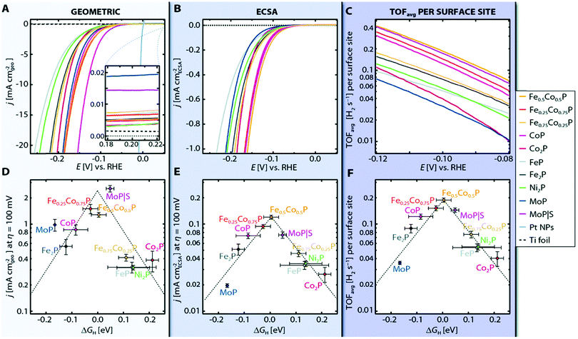 | ||
| Fig. 54 (a–c) HER activity of TMPs. (A) Linear sweep voltammograms (LVSs) per geometric area of representative TMP electrodes. The HER activity of Pt nanoparticles (NPs) is displayed for comparison. (d) Activity volcano for the HER showing the geometric current density from (A) at an overpotential of Z = 100 mV as a function of hydrogen adsorption free energy (DGH). (e) Activity volcano for the HER showing the ECSA normalised current density from (B) at Z = 100 mV as a function of DGH. (f) Activity volcano for the HER showing the average TOF from (C) at Z = 100 mV as a function of DGH. Reproduced with permission from ref. 928. Copyright RSC 2015. | ||
Amorphous nickel boride (Ni2B) as well as heterogeneous mixtures of nickel boride and nickel were checked for their electrocatalytic HER properties in 1 M NaOH solution at 70 °C by Los et al.931 At only 113 mV overpotential a current density of 250 mA cm−2 was reached, which is a fantastic performance, assuming the simplicity of the electrode preparation procedure.
Nickel boride, with which the development of HER electrodes based on metal boride was started, is still being discussed and further developed.932–937 Thus, electroless plated NiB0.54 film exhibited high activity for electrocatalytic H2 evolution (j = 10 mA cm−2 at overpotentials (η) of 45 mV in 0.5 M H2SO4, 54 mV in 1.0 M pH 7 phosphate buffer solution (PBS), and 135 mV in 1.0 M KOH).933
MoB, purchased from commercial sources, was used as a working electrode supporting hydrogen evolution upon using a Pt counter electrode in alkaline (pH 14) and acidic regime (pH 0) by Vrubel et al.938 MoB was found reasonably-active (η = 195 mV, j = 10 mA cm−2, pH 0; η = 200 mV, j = 10 mA cm−2, pH 14) and very stable for the HER. In addition, the HER activity of MoB derived from repeated CV measurements, improves as the number of repeated scans increases. Moreover, the activity determined at pH 0 and pH 14 is almost equal, which seldom happens (Pt is one such catalyst939). The authors explain the increasing HER efficiency of MoB electrodes by progressive reductive removal of surface oxides from the surface upon HER. The increase in efficiency could, however, also be caused by the Pt transfer from the counter to the working electrode, as already discussed above. The experiments conducted by Vrubel et al.938 should therefore be reproduced/verified and all electrochemical experiments should be carried out in accordance with established protocols of best electrochemical practice.1744
Commercially available powders of TiB2, WB and ZrB2 as prospective hydrogen evolution electrocatalysts in 0.1 M sulphuric acid have been evaluated by Wirth et al.940 The HER activity (derived from Tafel measurements) was rather mediocre with overpotentials of 800 mV required for j = 20 mA cm−2.
Powder consisting of amorphous CoB nanoparticles generated through a precipitation route was pressed to obtain pellets that have directly been used as HER electrodes.941 Highly active Co sites are, created by electronic transfer from B to Co obviously responsible for the very good HER activity and the robustness of the electrode at pH 1, 4.4 and 9.2 (Fig. 55). The catalyst performed best at pH 9.2 resulting in j = 20 mA cm−2 current density at an overpotential of η = 170 mV.
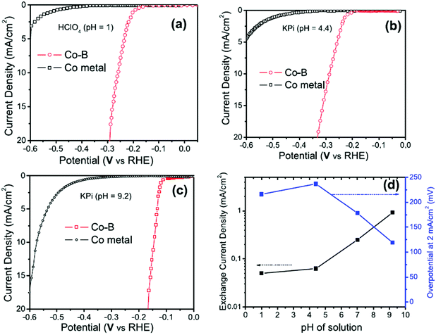 | ||
| Fig. 55 Linear polarisation curves with iR correction for CoB catalyst compared with Co metal in (a) pH 1 (0.1 M HClO4), (b) pH 4.4 (0.5 M KH2PO4) and (c) pH 9.2 (0.4 M K2HPO4) obtained with scan rate of 10 mV s−1. (d) Plot of overpotential (at 2 mA cm−2) and exchange current density values as a function of pH values of the solution used to test the CoB catalyst. Reproduced with permission from ref. 941. Copyright Wiley 2019. | ||
Amorphous cobalt boride with a stoichiometry close to 1.9![[thin space (1/6-em)]](https://www.rsc.org/images/entities/char_2009.gif) :
:![[thin space (1/6-em)]](https://www.rsc.org/images/entities/char_2009.gif) 1 (Co1.9B) was synthesised via reduction of CoCl2 with NaBH4 in aqueous solution by Masa et al.942 The heat-treated material exhibited reasonable activity for HER activity: j = 30 mA cm−2 at η = 300 mV in 1 M KOH.
1 (Co1.9B) was synthesised via reduction of CoCl2 with NaBH4 in aqueous solution by Masa et al.942 The heat-treated material exhibited reasonable activity for HER activity: j = 30 mA cm−2 at η = 300 mV in 1 M KOH.
Three different categories of boride-based materials have been investigated in the last 4 years as highly active compounds for electrocatalysis of hydrogen evolution: (i) hybrid materials with binary metal borides;943,944 (ii) ternary945-, quaternary946,947 metal borides; (iii) noble metal borides.948,949
From the point-of-view of HER efficiency (determined in acidic regime) the most convincing results were achieved with Pd2B.948 Pd2B nanosheets supported on carbon were synthesised via a two-step sol–gel/solvothermal approach using Pd(II) acetylacetonate as Pd precursor (Fig. 56). Pd–B forms a stable alloy; hcp phase is the thermodynamically most favored structure with B in the octahedral sites of the Pd lattice (Fig. 56a and b) and is reached at 120 °C (Fig. 56f); with only 15.3 mV overpotential at j = 10 mA cm−2 Pd2B even surpassed Pt/C (η = 30.1 mV; j = 10 mA cm−2; 0.5 M H2SO4).
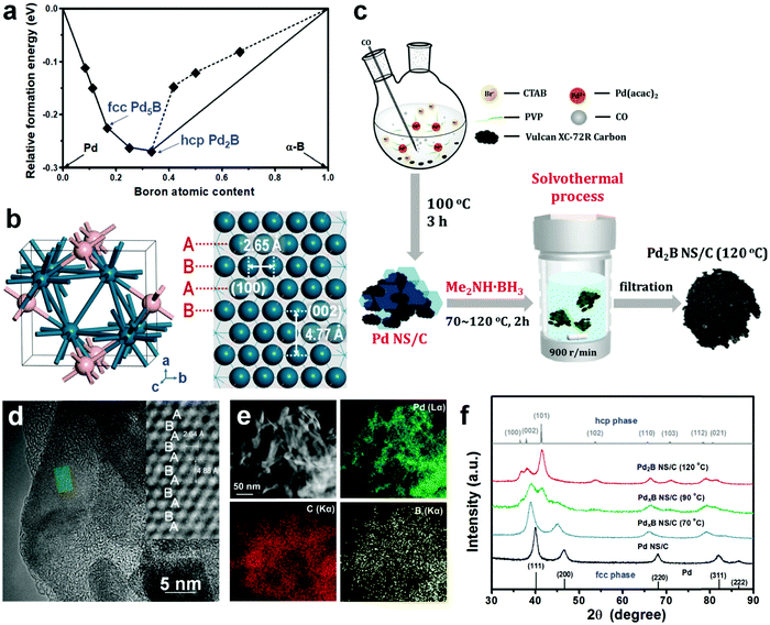 | ||
| Fig. 56 (a and b) DFT results for Pd–B alloy formation energy convex hull and hcp Pd2B crystal.22 (c) Schematic representation of the synthetic route for Pd2B NS/C. (d) HRTEM image of Pd2B NS. The inset is the magnified image of the rectangular region in (d). (e) STEM image and STEM-EDS element mapping Pd2B. (f) XRD patterns illustrating the phase transformation from Pd (fcc) to Pd2B (hcp) at different reaction temperatures. Reproduced with permission from ref. 948. Copyright RSC 2019. | ||
Rutheniumboride (RuB2) was proven a good HER electrocatalyst at pH 0, too (η = 100 mV; j = 50 mA cm−2) and its bifunctionality (Fig. 57) allows full water splitting at a low cell voltage of 1.525 V (j = 10 mA cm−2).949
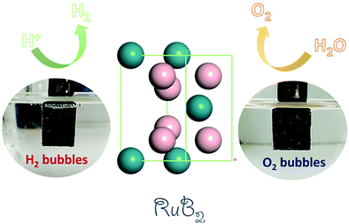 | ||
| Fig. 57 Schematic representation of the use of RuB2 as an anode and cathode in a water electrolysis approach. Reproduced with permission from ref. 949. Copyright American Chemical Society 2020. | ||
If high HER current densities (>100 mA cm−2) are sought, a ternary metal boride was shown advantageous over competitors (Fig. 58a):945 the HER activity of Cr1−xMoxB2 (x = 0, 0.25, 0.4, 0.5, 0.6, 0.75) follows the same canonic-like behaviour as the c lattice parameter (Fig. 58b), i.e. the ternary representatives of the sample series showed higher HER activity (Fig. 58a), the maximum being achieved with Cr0.4 Mo0.6B2 (Fig. 58a, c and d). Remarkably, Cr0.4 Mo0.6B2 even outperformed Pt/C at high HER current densities (>500 mA cm−2, Fig. 58c).
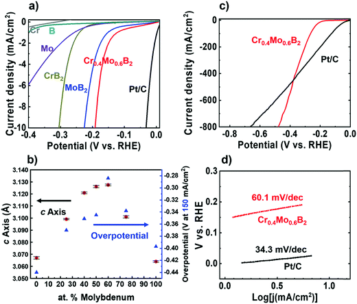 | ||
| Fig. 58 Linear sweep polarisation curves of different materials recorded in 0.5 M H2SO4 (current density normalised with the electrode's geometric surface area). (b) Plots of the lattice parameter c and the overpotential (at 150 mA cm−2 current density) as a function of molybdenum content. (c) Linear sweep polarisation curves showing the high current density behaviours of Cr0.4Mo0.6B2 and 20% Pt/C. (d) Tafel plots of Cr0.4Mo0.6B2 and 20% Pt/C. Reproduced with permission from ref. 945. Copyright Wiley 2020. | ||
Very recently quaternary borides (e.g., nickel-cobalt-molybdenum-boride: Ni-CMB) were considered;946 nickel incorporation on Co sites being claimed to significantly increase the conductivity. Convincing alkaline HER catalytic activity was shown from long-term chronopotentiometry (η = 130 mV; j = 100 mA cm−2; 1.0 M KOH).
The results shown above clearly demonstrate that borides can be amongst the best HER electrocatalysts in terms of both activity and durability.
The HER electrocatalysis via carbides was later on taken up by Harnisch et al.966 A mixture of different tungsten carbide species WC and W2C together with W and WO2 has been synthesised via reductive carburisation.981 It turned out that WC was the part of the mixture with the highest HER activity (η = 400 mV; j = 30 mA cm−2; pH 7). In addition to MoB,
In addition to MoB, Vrubel's report also includes the corresponding carbide (Mo2C).938 Whereas in acidic (pH 0) MoB and Mo2C exhibited the same HER activity (Fig. 59a) with an overpotential of 195 mV for j = 10 mA cm−2 (Fig. 59b), in base (pH 14), Mo2C was significantly more efficient than MoB (η = 160 mV; j = 27 mA cm−2; pH 14).
 | ||
| Fig. 59 (a) Polarisation curves (10th) of MoB and Mo2C at pH 0 and 14. Scan rate = 1 mV s−1. MoB, pH 0, 2.5 mg cm−2 (- - - -); MoB, pH 14, 2.3 mg cm−2 (—●—); Mo2C, pH 0, 1.4 mg cm−2 (—); Mo2C, pH 14, 0.8 mg cm−2 (—▲—). The iR drop was corrected. (b) Time dependence of catalytic currents during electrolysis over 48 h for MoB and Mo2C at pH 0 and 14. The iR drop was corrected. MoB, pH 0, −195 mV (- - - -); MoB, pH 14, −200 mV (—●—); Mo2C, pH 0, −195 mV (—); Mo2C, pH 14, 0.8 mg cm−2 (—▲—). Reproduced with permission from ref. 938. Copyright Wiley 2012. | ||
Adzic et al. investigated molybdenum carbide (β-Mo2C) nanoparticles supported either by carbon nanotubes (CNT) or carbon black (XC-72).1348 Mo2C/CNT performs best in the HER in 0.1 M HClO4 within the sample series (η = 63 mV; j = 1 mA cm−2), followed by Mo2C/XC-72 and Mo2C and Mo metal (Fig. 60).
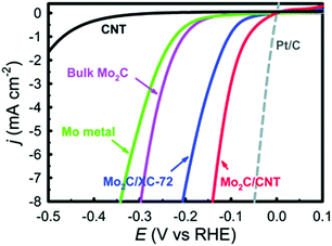 | ||
| Fig. 60 The polarisation curves of nanostructured Mo2C/CNT, Mo2C/XC, bulk Mo2C, Mo metal, Pt/C and CNT in 0.1 M HClO4. Reproduced with permission from ref. 1348. Copyright RSC 2013. | ||
Mo2C nanoparticles stabilised by a carbon layer on reduced graphene oxide (RGO) sheets turned out to be a durable HER electrocatalyst (η = 140 mV; 13.8 mA cm−2; 0.5 M H2SO4).982 A comparable HER activity determined in 0.5 M sulphuric acid was obtained by Girault et al. for Mo2C nanowires.983 Nanosised Mo2C is also accessible via a reactive template route based on C3N4 however pure carbides (nitrogen free) require high decomposition temperatures (>1500 K).984
Youn et al. investigated Mo2C, MoS2 and Mo2N nanoparticles anchored on carbon nanotube (CNT)-graphene hybrid support and found that the carbide-type hybrid is the best HER catalyst (Fig. 61a and b).985
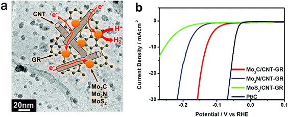 | ||
| Fig. 61 (a) Schematic illustration of Mo2C-, Mo2N-, and MoS2-nanoparticles anchored on carbon nanotubes (in turn) attached to graphene and the corresponding discharging of H+ ions leading to HER. (b) Polarisation curves derived from the nanoparticle-CNT-graphene hybrid electrocatalyst. Measurements were performed in 0.5 M H2SO4. Reproduced with permission from ref. 985. Copyright American Chemical Society 2014. | ||
Besides beta phase Mo2C (Fe2N structure) the synthesis and catalytic testing of three other phases (α-MoC1−x, η-MoC and γ-MoC) was shown by Leonard et al.986 γ-MoC was the most stable for acidic HER. However, as confirmed by other researchers, β-Mo2C has the highest HER activity Fig. 61b.
In order to further improve the overall HER properties, metal ion doping of metal carbides was attempted, producing, for example, ternary metal carbides. Hybrid materials with a more complex architecture, which include (binary) metal carbides, were also generated as potential HER electrocatalysts.987–1001
Due to the large number of publications in this area, we have selected three recently-published articles which, regardless of the number of citations they received, guarantee a certain variety in terms of novelty, catalytic activity, synthesis strategy, design criteria and the type of material examined.
A catalyst made from renewable raw materials fulfill sustainability criteria in a perfect way. Humagain et al. recently reported on porous Mo2C HER electrocatalyst, synthesised using forestry residue biochar as a carbon source1002 (Fig. 62).
 | ||
| Fig. 62 Schematic representation of biochar formation. Reproduced with permission from ref. 1002. Copyright Wiley 2018. | ||
Reduction of a Mo/biochar composite by Mg at 650 °C followed by purification steps resulted in β-Mo2C (Fig. 63). This catalyst material designed from regrowable resources turned out to highly actively and stably supporting HER in 0.5 M H2SO4 (η = 35 and 60 mV, j = 10 mA cm−2, 100 mA cm−2 respectively).
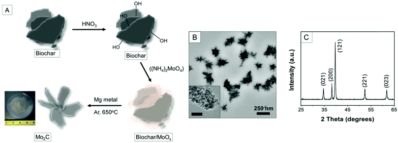 | ||
| Fig. 63 (A) Schematic representation of synthesis of Mo2C nanostructures. (B) TEM image (inset: scale bar = 25 nm) and (C) the powder XRD pattern of Mo2C derived from biochar. Reproduced with permission from ref. 1002. Copyright Wiley 2018. | ||
Precious metal carbides do not appear in the precious metal-carbon phase diagrams and a sensible synthetic method to generate precious metal carbides has not been established until recently. Two years ago, rhodium carbide (Rh2C) was synthesised through a sol–gel synthesis route at high temperatures using Rh(III) acetylacetonate as metal precursor and tetracyanoethylene (TCNE)1003 (Fig. 64 and 65). Fig. 65b shows the free energy diagram of H* on OH*pre-covered surfaces. The catalyst-H adduct shows a free energy close to zero and such species are regarded as highly active towards promoting the HER. Indeed, Rh2C exhibits a comparable HER activity to Pt (Fig. 65a).
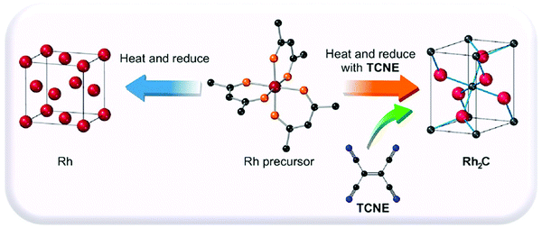 | ||
| Fig. 64 Schematic presentation of the synthesis of Rh2C. Reproduced with permission from ref. 1003. Copyright American Chemical Society 2020. | ||
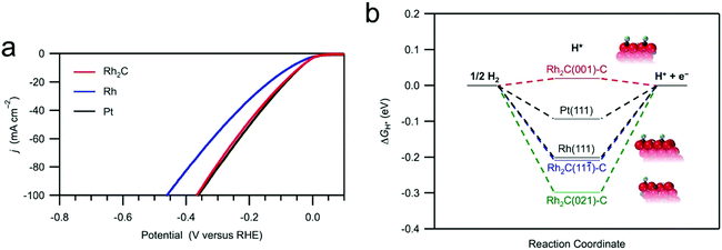 | ||
| Fig. 65 (a) The HER polarisation curves of 20 wt% Rh2C/C (red), Pt/C (black), and Rh/C (blue). The data were recorded in a 1.0 M KOH electrolyte with a scan rate of 50 mV s−1. (b) The 3-state free energy diagram for HER. The structural models show the OH* pre-covered surfaces used for calculations. The blue spheres are hydrogen atoms, and the gray spheres are oxygen atoms. Reproduced with permission from ref. 1003. Copyright American Chemical Society 2020. | ||
Although nano-scaled transition metal carbides have become an emerging class of HER active materials,1004 conventional phase diagrams fail to precisely describe the phase stability of nanocrystalline materials. DFT calculations were used to determine the volume and surface energies for known Mo and W carbide phases, and the results of all efforts were combined by creating particle size-dependent phase diagrams1005 (Fig. 66a): bigger particles are more likely to end up in β-Mo2C and γ-MoC. Fig. 66b presents the inverse average particle size vs. (synthesis) temperature diagram derived from experimental reports. Generally high synthesis temperature will lead to bigger particles; bulk material is very often achieved through high-temperature solid-state reactions and if (T > 600 K) more frequently led to beta phased Mo2C or reports dedicated to bigger particles are more frequently based on beta-phased material. The theoretical predictions (Fig. 66a) are confirmed by the experimental findings (Fig. 66b and c).
 | ||
| Fig. 66 (a) Lowest energy 2-D phase diagram by projecting 3-D diagram onto ΔμC − 1/d axis. (b) Inverse average particle size vs. temperature for experimental reports. For clarity, plasma-based syntheses were omitted from Fig. 66b. (c) Stacked bar graph for percentage of experimental reports at given average particle sizes. Reproduced with permission from ref. 1005. Copyright American Chemical Society 2020. | ||
A huge number of scientific papers are dedicated to studies that deal with HER on metal-carbide-based compounds: more than 2000 articles can be assigned to this content (ISI-Thomson-Reuters). The content of this work can be aptly summarised with the statement that the catalytic activity of metals can be increased by alloying with C and is on par with that of the reference material Pt or platinum on carbon (Pt/C).
7.5.3.1 Metal nitrides as electro catalysts to support the hydrogen evolution reaction. All readers of this article have certainly seen at least one representative of the transition metal nitride, less in a laboratory than in a hardware store: the gold-coloured TiN coated twist drills. Transition metal nitrides are accessible by high-temperature metals nitriding with N2,940 by nitriding metal precursors with ammonia1007,1008 (less often) by high-frequency plasma treatment in N2,1009via high vacuum-supported approaches like chemical vapor deposition,1009via high vacuum supported approaches like chemical vapor deposition1010,1011 or via physical vapor deposition directly from the metal in nitrogen atmosphere upon reactive sputtering.1012,1013 The high-temperature approaches to some extent suffer from O and C contaminations, which may affect the catalytic properties.
Similar to carbides, formatting early transition-metal nitrides modifies the nature of the d-band of the base metals and leads to different catalytic properties than for the parent metals (that more closely resemble those of Group VIII noble metals).918,1014 In addition, the electric conductivity of transition metal nitrides is in the metallic range. In general, early transition metal nitrides exhibit excellent activities for catalysing diverse reactions:1015,1016 for example, molybdenum nitride acts near-similarly to platinum for hydrocarbons hydrogenolysis. Although already used 15 years ago for the photocatalytically-initiated hydrogen evolution,11,1017,1018 metal nitrides were only used for the electrocatalytical HER since 2011.1347 We already tried to reasonably explain why metal oxides are more sensitive to negative electrode potentials than sulphides, with the consequence that oxides are used more as OER electrode materials than as HER electrode materials. This could also explain why some metal nitrides (CoN,1026 Co4N,1019 Fe3N/Fe4N1020) have amazing activity for the OER rather than for the HER (N is electronegative). Recently, several reviews have been published that deal with transition metal nitrides as potential electrode material for water electrolysis purposes.1021–1025
Among the binary metal nitrides molybdenumnitride stands out in some ways as this type of material has been more intensively investigated as a potential HER electrocatalyst.1026–1029
The HER activity of carbon-supported Nickel-Molybdenum nitride (NiMo4.7Nx/C) was determined in 0.1 M HClO4 and found adequate (η = 200 mV; j = 3.5 mA cm−2) but not competitive with current HER electrocatalysts, e.g., of the carbide family.1347 Wirth et al. investigated besides borides, carbides, sulphides and carbonitrides a series of transition metal nitrides (AlN, Ta3N5, TiN) derived from industrial manufacturing routes as potential HER electrodes in 0.1 M sulphuric acid;940 the nitrides did not prove show active (η = 763 mV (Ta3N5)–973 mV (AlN); j = 20 mA cm−2.
Khlaifah and co-workers achieved a breakthrough with respect to the development of transition metal-based nitrides with at least reasonable HER catalytic activity.1030 Cobalt molybdenum nitride (Co0.6Mo1.4N2) exhibited, as revealed from neutron powder diffraction data, a layered structure with alternating layers of trigonal prismatic and octahedral coordination for the Mo and Co (Fig. 67) and was found to reasonably catalyse the HER (η = 250 mV; j = 10 mA cm−2; 0.1 M HClO4).
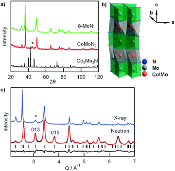 | ||
| Fig. 67 (a) Lab X-ray powder diffraction patterns of Co3Mo3N, CoMoN2, and δ-MoN. Asterisk marks the impurity peak of cobalt metal. (b) Four-layered crystal structure of CoMoN2. (c) Rietveld refinements of neutron diffraction for CoMoN2 showing observed data (black line), calculated pattern (red line) and difference curve (bottom line). Lab X-ray diffraction data (blue line) in same Q (= 2π/d) range between 2 and 7 Å−1 do not clearly show superstructure peaks such as the 013 and 015 reflections which are intense in neutron diffraction data. Reproduced with permission from ref. 1030. Copyright American Chemical Society 2013. | ||
Co-Mo5N6, at first sight a similar-composed material, turned out to be a composite with coexisting metallic cobalt and a nitrogen-rich molybdenum nitride phase.1031 It's HER performance is among the best ever published (η = 19 mV; j = 10 mA cm−2; Tafel slope = 29.0 mV dec−1; 1.0 M KOH, Fig. 68).
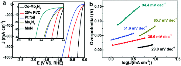 | ||
| Fig. 68 Electrochemical measurements. (a) HER polarisation curves of the samples in 1.0 M KOH. (b) Corresponding Tafel plots. Reproduced with permission from ref. 1031. Copyright Wiley 2020. | ||
In general, there is no deep evidence that nitrogen atoms act as the HER active sites; one rather assumes that N centers in nitrides are simple spectators.1014 To more easily study HER mechanism, some scientists rather did a U-turn and investigated (again) binary metal nitrides.1032
The first work that reports on molybdenum nitride that has proven good characteristics for HER catalysis appeared in 2014.1032 Atomically thin molybdenum nitride (MoN) nanosheets prepared by liquid exfoliation of the bulk material in N-methyl-pyrrolidone (NMP) via ultrasonication. Apical Mo atoms on the surface of the nanosheets present the catalytic active sites which feeds the assumption that through nitriding Mo behaves like precious metals. However, from a performance standpoint, MoN (η = 300 mV; j = 37 mA cm−2; 0.5 M H2SO4) is still a long way from platinum. Youn et al.985 and Ma et al.1033 confirmed that in direct comparison with carbides, nitrides of the same family (Mo2C, Mo2N) cannot keep up in terms of efficiency.
Substantially better HER performance was shown by Shalom et al. for Ni3N grown on Ni foam1034 (η = 500 mV; j = 100 mA cm−2; 1 M KOH). The capability of Ni3N to efficiently promote HER was later confirmed by different groups.1035–1037
Bimetallic nickel-based nitrides, i.e., ternary metal nitrides comprising nickel were found slightly more efficient compared to binary nickel nitride species:866,1038–1043 Ni3FeN nanoparticles866 are on par with Pt/C, in particular at high current densities (η = 300 mV, j = 100 mA cm−2), and similar for Ni2Mo3N nanoparticles grown on nickel foam (Fig. 69).1042
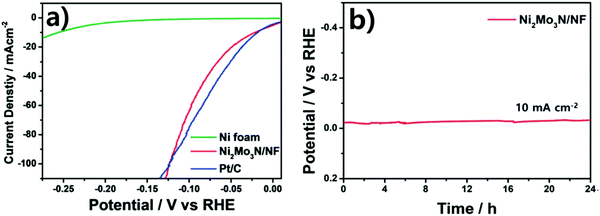 | ||
| Fig. 69 Electrochemical characterisation for the prepared catalysts. (a) Polarisation curves. (b) Stability measurement. Reproduced with permission from ref. 1042. Copyright RSC 2021. | ||
A very consistent implementation of the strategy to use bimetallic nitrides was recently shown by Yu et al.1044 NiFeN core NiMoN shell-architectured nanoparticles (NiMoN@NiFeN) as well as NiMoN core only particles (Fig. 70) were described as being even more efficient than Pt/C in HER experiments in 1 M KOH: η = 127 mV for j = 500 mA cm−2.
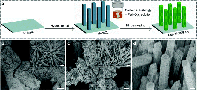 | ||
| Fig. 70 Synthesis and microscopic characterisation of the as-prepared NiMoN@NiFeN catalyst. (a) Schematic illustration of the synthesis procedures for the self-supported 3D core–shell NiMoN@NiFeN catalyst. (b–d) SEM images of (b) NiMoN and (c and d) NiMoN@NiFeN at different magnifications. Reproduced with permission from ref. 1044 Copyright Nature Publishing 2019. | ||
Another way that appears promising for the production of highly active transition metal nitrides for HER electrocatalysis is to choose those that contain noble elements to a certain extent.1045
We do not want to close this subsection until we have introduced another compound. Hexagonal boron nitride efficiently supports ORR1046 and has considerable hydrogen adsorption capability.1047 In fact, it was demonstrated by Uosaki et al.1048 that HER proceeds very efficiently on a nanosheet of hexagonal boron nitride (BNNS) on gold substrate.
As a summary the HER performance of most of the nitride-based electrocatalysts discussed so far is slightly below that of typical representatives of the boride or carbide type. However, some of the bimetallic nitrides and intelligently structured composites, including transition metal nitrides, in particular, have HER activities that are definitely among the best performances ever identified. Some publications claim that the metal centers act as catalytically active centers; however, solid confirmation of this hypothesis has not yet been published, making further optimisation difficult.
7.5.3.2 Metal phosphides as electro catalysts to support the hydrogen evolution reaction. Due to the enormous number of articles published on this topic, concision is awkward and can only be achieved by focusing on the pioneering work, and on groundbreaking results (heavily cited) results. Additional literature is also accessible, which summarises the collected results very well in the form of review articles,.58,1049–1053
Several decades ago, metal phosphides, at that time basically synthesised starting from highly reactive elemental phosphorus, were used in the field of metallurgy, hydrodesulphurisation, pesticides and for photocatalytic degradation.1054,1055 Photocatalytically-initiated hydrogen evolution on the phosphide-solution interface has been the topic of several papers published in the 1970 s.1056,1057
Pioneering work by Paseka and Burchardt showed that amorphous phosphides are able to promote HER in alkaline medium at low overpotentials.1058,1059
Rodriguez and co-workers proposed that the (001) surface of Ni2P combines the favourable H-bonding of the hydrogenase systems with the thermal stability of a heterogeneous catalyst.1060 Other researchers noticed the potential mechanistic analogy between hydrodesulphurisation (HDS), the catalytic process by which sulphur impurities are removed from hydrocarbon fuels, and HER. Ni2P, one of the most active HDS catalysts,1061 should therefore be a promising HER electrocatalyst which was experimentally confirmed by the groups of Lewis and Schaak.1259 Ni2P nanoparticles (Fig. 71) highly actively and durably supports HER in 0.5 M H2SO4 (Fig. 72): η = 130 mV for j = 20 mA cm−2. Shortly after, Hu's group confirmed the ability of Ni2P for HER catalysis.1062
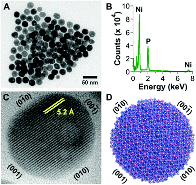 | ||
| Fig. 71 (A) TEM image and (B) EDX spectrum of Ni2P nanoparticles. (C) HRTEM image of a representative Ni2P nanoparticle, highlighting the exposed Ni2P(001) facet and the 5.2 Å lattice fringes that correspond to the (010) planes. (D) Proposed structural model of the Ni2P nanoparticles. Reproduced with permission from ref. 1259 Copyright 2013 American Chemical Society. | ||
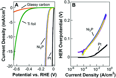 | ||
| Fig. 72 (A) Polarisation data for three individual Ni2P electrodes in 0.5 M H2SO4, along with glassy carbon, Ti foil, and Pt in 0.5 M H2SO4, for comparison. (B) Corresponding Tafel plots for the Ni2P and Pt electrodes. Reproduced with permission from ref. 1259 Copyright 2013 American Chemical Society. | ||
The field of metal phosphide HER catalysts has expanded since then rapidly. A variety of binary, ternary and higher order metal phosphides with e.g., high-symmetry ionic crystal structures like NaCl type or more complex structures have been synthesised and checked for their electrocatalytic properties. The electrical conductivity differs depending on the composition and M-P bond (ionic, metallic or covalent) and ranges from semiconducting to metallic to superconducting.
Depending on the composition, the chemical properties also vary, which, for example, leads to an inertia in relation to the dissolution in acids/bases or which makes them easily soluble (Cd- or Zn phosphide) thereby affecting its suitability to act as an HER electrocatalyst. Basically Fe, Ni, Co, Cu, W and Mo phosphides were found promising cathode materials for water electrolysis. Based on DFT approaches, the P atom plays a major role for the catalytic activity of metal phosphide in metal phosphides. The ability of metal phosphides to act as proton-reducing species (to initiate HER) stands and falls with the trend of the negatively-charged P atom to donate electrons. Thus, for the same metal phosphide, increasing the percentage of P in the total number of atoms is known to enhance the HER activity (Ni5P4 > Ni2P)1063 and an increased P content leads to better corrosion resistance.1064 On the other hand, if P is continuously doped in metals, the conductivity decreases.926
Metal phosphides have been prepared in various forms (bulk, single crystals, films, nanoscaled solids) and, depending which form is intended, are accessible via various synthesis routes comprising solid state reaction of the elements and red phosphorous at high temperature,1065 solid state reaction of reactive metal phosphides with transition metals,1066 phosphidation of metal oxides,-hydroxides or reduction of metal phosphates,1067 solvothermal approaches,1068 organometallic precursor-based routes performed in high boiling solvents1069 and high vacuum CVD or PVD-based techniques.1070–1072
Originally the HER properties of Ni2P were checked in alkaline-1062 and in acidic regime.1259 Meanwhile transition metal phosphides have also been shown to be active HER supporting catalysts under neutral pH conditions.1073 Several strategies have been exploited to further enhance the electrocatalytic activity of phosphide-based HER electrocatalysts. Among them (i) developing HER active compounds with hydrophilic and aerophobic surfaces; (ii) increasing the conductivity of the electrocatalyst by firmly attaching the HER active (phosphide-based compound) phase to e.g., CNTs, graphite, graphene;1074–1076 (iii) doping metal phosphides with other metals to bimetallic phosphides;1077 (iiii) doping of metal phosphides with other nonmetals.1078 The most widely studied materials in relation to phosphide-based-electrode materials for water electrolysis include nickel phosphides (Ni2P;1062,1079,1253 Ni5P4;1080,1081 Ni12P5,1082,1083 cobalt phosphides (CoP,1084–1088 Co2P,1064,1079,1089 CoP21090,1091), molybdenum phosphides (MoP,1092,1093 Mo3P,1093 MoP21094), tungsten phosphides (WP,1095,1096 WP21097,1098), iron phosphides (FeP,1099–1104 Fe2P,1079,1105 FeP21100,1106). The best results collected up to 2016 for binary nickelphosphides for HER electrocatalysis in 0.5 M H2SO4 were achieved with Ni5P4 (η = 23 mV; j = 10 mA cm−2),1080 (η = 62 mV; j = 20 mA cm−2).1081 CoP showed the best HER efficiencies that were achieved with the help of binary cobalt phosphides (η = 48 mV; 10 mA cm−2),1087 (η = 59 mV; 20 mA cm−2) in the same electrolyte. Among the binary iron phosphides FeP turned out to be superior to Fe2P or FeP2 based HER electrocatalysts (η = 34 mV; j = 10 mA cm−2 and η = 43 mV; j = 20 mA cm−2).1104 A much lower HER efficiency was obtained when acidic HER was catalysed by binary molybdenum, tungsten- or copper1107 phosphides. Among this type of electrocatalysts, MoP exhibited the best results in 0.5 M H2SO4 (η = 90 mV; j = 10 mA cm−2 and η = 105 mV; j = 20 mA cm−2).1092
It can generally be said that binary transition metal phosphides perform worse for alkaline HER than in acids: at pH 14, FeP1108 and CoP1073 required overpotentials in the 200 mV range for j = 10 mA cm−2. Metal doping, i.e., conversion of binary metal phosphides to ternary- or quaternary metal phosphides, was found efficient to increase the metal phosphide efficiency for alkaline HER electrocatalysis: (Ni0.33Fe 0.67)2P leads to η = 214 mV at j = 50 mA cm−2 in 1 M KOH.1109 HER electrocatalysis at pH 14 upon the ternary phosphide MoCoP was actively and durably promoted as well (η = 40 mV; j = 10 mA cm−2).1110 One of the best HER performances determined for HER electrocatalysis in alkaline medium upon phosphides was achieved with WniCoP: η = 30 mV for j = 10 mA cm−2.1111
Composites with coexisting phases that differ in terms of their chemical nature and that are in close contact present unique interfacial interactions.1112
In 2018 Zhang et al. reported on Ni5P4 nested on NiCo2O4 (Ni5P4@NiCo2O4, Fig. 73) as a heterogeneous structured HER electrocatalyst generated by phosphating of NiO firmly attached to NiCo2O4: Ni5P4@NiCo2O4 exhibited very good HER activity (η = 27 mV for j = 10 mA cm−2; 1.0 M KOH).
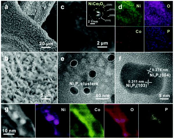 | ||
| Fig. 73 (a) SEM image showing the uniformly distributed Ni5P4@NiCo2O4 nanoflakes on graphene/Ni foam. (b) High-magnification SEM image of Ni5P4@NiCo2O4 nanoflakes. (c) Low-magnification TEM image and (d) corresponding energy dispersive spectroscopy (EDS) elemental mapping images of Ni5P4@NiCo2O4 nanoflakes. (e) High-resolution TEM image showing that nanometric Ni5P4 clusters are nested on the nanoflakes. (f) HRTEM image of one single Ni5P4 nanocluster. (g) HRTEM image and corresponding elemental mapping images of Ni5P4@NiCo2O4. Reproduced with permission from ref. 1112 Copyright Wiley 2018. | ||
In 2020 and 2021, more than 1000 articles were found with the search terms “phosphide hydrogen evolution” (ISI web of knowledge). Extremely active phosphide-based-HER electrocatalysts were very recently developed for acidic1113–1116 and alkaline HER electrocatalysis.1117–1119
Duan et al. investigated the special role of phosphorous vacancies in nickel phosphide to boost the HER efficiency in alkaline solution by two orders of magnitude1119 (Fig. 74). Possible P-defective sites are obtained using high resolution TEM (Fig. 74g). Ni12P5 with vacancies (v-Ni12P5) outperformed non-defective Ni12P5 (p-Ni12P5) as well as Pt/C with respect to HER efficiency in polarisation measurements carried out in 1 M KOH (Fig. 75).
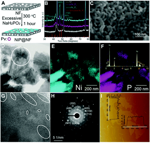 | ||
| Fig. 74 Synthesis and characterisation of catalysts. (A) Synthesis procedure. (B) XRD patterns. (C) SEM image. (D) TEM image. (E and F) TEM EDS elemental mapping images of Ni and P; inset: EDS spectrum. (G) High-resolution TEM image; white circles mark the possible Pv areas. (H) SAED of the white circle area in panel (D). (I) AFM image; insets: height distribution curves; note that (C–I) all show images/data for v-Ni12P5. Reproduced with permission from ref. 1119 Copyright Wiley 2020. | ||
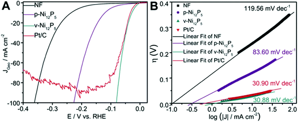 | ||
| Fig. 75 Electrochemical measurements. (A) Polarisation curves. (B) Tafel plots. Reproduced with permission from ref. 1119 Copyright Wiley 2020. | ||
As a summary of Section 7.5.3.2, it can be said that the latest findings impressively confirm the outstanding efficiency of phosphide based HER electrocatalysts.
Transition metal chalcogenides are accessible through solvothermal aproaches,1155 electrodeposition,1783 high-vacuum-supported deposition methods (PVD and CVD1129), exfoliations (top-down approaches), e.g. realised through sonication1130 and intercalation1131,1132 as well as upon bottom-up strategies (e.g. injection of a precursor solution to a (hot) metal precursor solution (hot injection method)).1133
From the late 1970s onwards, transition metal chalcogenides began to be considered as HER electrode material in water electrolysis,1134 while use for photocatalytic water splitting began about 4 years later.1135
Vandenborre et al. published the first journal report dealing with electrocatalytic HER on pure metal chalcogenides appeared in 1984: NiS2 led to j = 30 mA cm−2 at around η = 100 mV in 1 M NaOH, which is a respectable efficiency value.1136
Little research has been undertaken in the following years on this field. This research received a kind of initial spark with the in-depth investigation of MoS2 material, widely used in industry for the hydrodesulphurisation of petroleum, which was identified as an efficient HER catalyst in acidic media based on the theoretical and experimental results of Nørskov and co-workers1137 and Chorkendorff and co-workers.1703 The computational results predicted that graphite-supported MoS2 should be a good HER electrocatalyst.1137 This was experimentally confirmed upon using MoS2 nanoparticles supported on carbon (η∼200 mV; j = 50 mA cm−2; Fig. 76).1137 MoS2 remained in the focus of interest of numerous researchers.1140
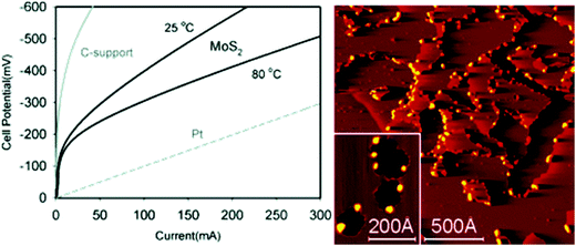 | ||
| Fig. 76 Polarisation curve for hydrogen evolution on Pt, daihope C-support, and MoS2 cathodes. The potentials are measured with respect to a carbon-supported Pt anode in a proton exchange membrane electrode assembly. (Right) STM images of MoS2 nanoparticles on modified graphite. Reproduced with permission from ref. 1137 Copyright 2005 American Chemical Society. | ||
Li et al. showed that S-vacancies in MoS2 create gap states that allow favourable hydrogen adsorption.1139 Strained MoS2 with S vacancies proved to be a competitive HER electrode material η = 200 mV; j = 20 mA cm−2; pH 0.2). Long before appearance of this work lattice strain engineering proved to be a powerful tool to tune the electronic structure hence the electrocatalytic properties.1152
To date many transition sulphides, selenides and some tellurides exhibited competitive HER: MoS2,1138–1140 MoS3,1141 MoSe2,1142 CoS,1143 Co9S81144 CoSe2,1145 Co7Se8,1146 NiMo3S4,1147 CoSe2-SnSe2,1148 NiS2,1149 Ni3S2,1149 Ni3Se2,1150 NiS, NiSe,1151 NiS0.5Se0.5,1152 Ni3 S2-CdS,1153 MoS2 in Cu2S matrix,1154 FeS,1155 FeS2,1156,1157 FeSe,1158 Co doped FeSe21159 Ni3Bi2S2,1160 Bi2Te3,1161 MX2 (M = V, Nb, and Ta; X = S, Se, and Te),1162 TaS2,1163 CoTe2,1164 NiTe2,1164 MoTe2,1165 WS2,1166 WSe21167–1170 NiCo2S4,1455 MoS2-CuS,1171 CuS,1172 Cu2Se,1173 CoTe2-CdTe.1174
This list shows that sulphides and selenides are the most frequently investigated metal chalcogenides for water electrolysis (only some tellurides (MoTe21165) have been included in this investigation so far).
That is rather surprising because, from a theoretical point-of-view tellurides (in general) should not be less active than the lighter homologues of the sixth main group. Huang et al.1138 compared the reaction energy (ΔGH2) for the rate-determining Volmer step [MX2]H to [MoX2]H2 (for X = S–Te and M = Mo, W) and calculated the voltage required to obtain ΔGH2 = 0 (Voltage to balance [MX2]H and [MoX2]H2; Fig. 77): the voltage minimum of approximately 90 mV is reached for X = Te (MoTe2).
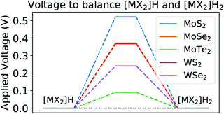 | ||
| Fig. 77 Required applied potential to obtain a zero-reaction energy for the rate determining Volmer step from [MX2]H to [MX2]H2. Reproduced with permission from ref. 1138 Copyright 2018 American Chemical Society. | ||
Different approaches are currently employed to increase the number of active sites and to improve the electrocatalytic properties of metal chalcogenides. For instance, the optimisation of the chemical composition leads to an increase in the intrinsic electrocatalytic activity, which in turn is based on a reduction in the free hydrogen adsorption energy ΔGH (intrinsic).1139 The optimisation of the structure leads to an increase in the number of catalytic active sites, hence an increase in the extrinsic catalytic activity.1152
A special realisation of the structure optimisation results from the creation of heterostructured systems, in which e.g., identically composed compounds are in close contact with each other such as nanorods and sheets (of the same material); or different crystalline phases of materials with identical stoichiometry form a nanostructured composite. In addition, lattice strain engineering (see above) is a powerful tool for structure optimisation.
A series of lattice-strained homogeneous NiSxSe1−x nanorod@nanosheet hybrid (homogeneous composed but heterostructured NiSxSe1−x) firmly attached to Ni foam have been synthesised upon a hydrothermal route (Fig. 78):1152 the NiS0.5Se0.5 representative with 2.7% lattice strain is ideally able to support HER + OER at overvoltages of 70 mV (HER) or 257 mV (OER) (j = 10 mA) cm−2; 1 M KOH).
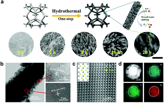 | ||
| Fig. 78 Synthesis and structural characterisations. (a) Schematic illustration of the synthetic procedures of NiSxSe1−x nanocomposites. The scale bars for SEM images are 2 μm. (b) TEM and HRTEM images of NiS0.5Se0.5. (c) Atomic-resolution HAADF-STEM image (inset shows the corresponding schematic atom arrangement). (d) HAADF-STEM and EDS mapping images of NiS0.5Se0.5 from the cross-section view. Reproduced with permission from ref. 1152. Copyright Wiley 2020. | ||
A common feature of the papers published on this topic over the past two years is the significant increase in HER activity.1175–1180
Metallic vanadium sulphide (VSn) embedded in a MoS2 film (to result in a V-MoS2 film) are highly active HER catalysts, as shown by Kim's group:1178 VSn units are formed in the basal plane of MoS2 (Fig. 79), leading to an impressive HER current density of 1000 mA cm−2 at 600 mV overpotential during water electrolysis experiments.
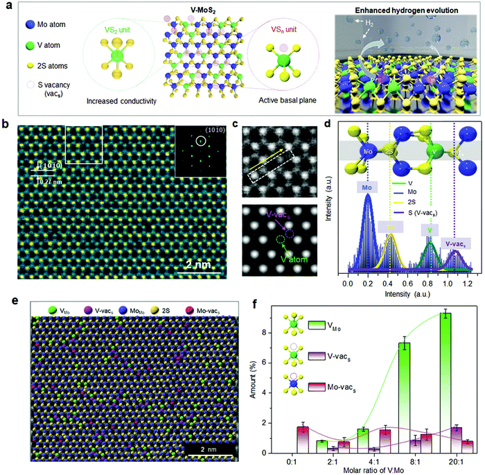 | ||
| Fig. 79 Atomic structure of monolayer V-MoS2. (a) Schematic of V–MoS2 with VS2 and VSn units and hydrogen evolution on V–MoS2via basal-plane activation. (b) ADF-STEM image at 9.3% V concentration, indicating a d-spacing of 0.27 nm for 2H–MoS2 and the corresponding electron-diffraction-pattern of (101–0) plane in the inset. (c) STEM image of white square region in (b) and simulated image and (d) the corresponding intensity profile. (e) False-coloured ADF-STEM image of monolayer V-MoS2 with Mo-substituted V atom (VMo), sulphur-vacancy next to V atom (V-vacs), Mo atom (MoMo), two S atoms (2S), and sulphur-vacancy next to Mo atom (Mo-vacs). (f) Atomic % distribution of VMo, V-vacs, and Mo-vacs as a function of molar ratio of V to Mo precursor. Statistical analysis data were obtained from false-coloured ADF-STEM images. Reproduced with permission from ref. 1178 Copyright Wiley 2021. | ||
A Mo–Ni–Co tri-metallic selenide nanorod arrays-based HER electrode turned out to be able to achieve high current densities (0.3 A cm−2) at acceptable overpotentials (η = 350 mV) as well1175 (Fig. 80).
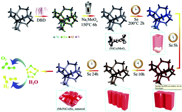 | ||
| Fig. 80 The schematic fabricating processes of MoSe2–NiSe2–CoSe2 nanorods on the PNCF surface. Reproduced with permission from ref. 1175 Copyright Elsevier 2020. | ||
To summarise, metal chalcogenides are without a doubt some of the most promising electrodes to promote the HER. However, most of them are not yet at the absolute benchmark level and need to be (further) modified. For example, materials that contain metal chalcogenide as part of a composite, e.g., in combination with metal phosphides or nitrides, achieve the efficiency of Pt/C or the best species discussed so far in Section 7.
WCN-based electrodes were found to highly actively and stably catalyse HER as shown by Zhao et al.1181 or by Chen et al.1182 A series of binary NiP2, NiSe2 and ternary NiPxSey compounds have been synthesised and checked for their HER catalytic capabilities:1183 NiP1.93Se0.07 exhibited the best HER performance (η = 84 mV; j = 10 mA cm−2; 0.5 M H2SO4). HER efficiency experienced a real boost from work that was published very recently.1179,1184–1189
Phosphorisation of NiSe2 nanoplate arrays delivered a self-supported electrocatalyst comprising a nickel chalcogenide (NiSe2) and a nickel pnictide (Ni2P) phase1188 (Fig. 81) and turned out to highly efficiently and stably support HER electrocatalysis in 1 M KOH (η = 66 mV; j = 10 mA cm−2).
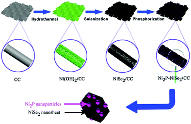 | ||
| Fig. 81 Schematic illustration of synthesis of Ni2P–NiSe2/CC heterostructure catalyst. Reproduced with permission from ref. 1188 Copyright Elsevier 2020. | ||
A very recently-published work aimed at improving the interface between a transition metal chalcogenide-based- and a transition metal phosphide-based phase.1185 Materials comprising MoS2/NiS2 phases (Fig. 82) were found to support HER electrocatalysis efficiently and stably with the MoS2/NiS2 material performing slightly better. In particular in alkaline media, these two-phase multi-element species significantly outperform Pt/C (Fig. 83).
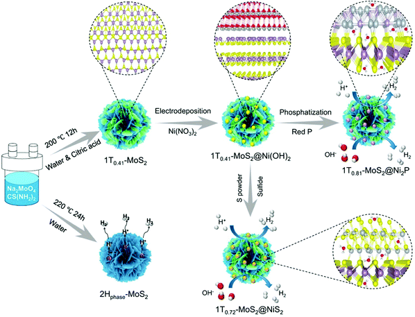 | ||
| Fig. 82 Schematics of the 1T0.72-MoS2@NiS2 and 1T0.81-MoS2@Ni2P synthesis steps. Reproduced with permission from ref. 1185 Copyright Nature Publishing 2021. | ||
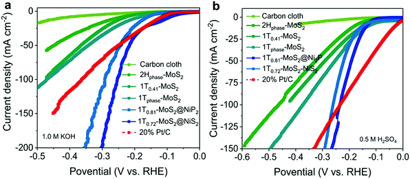 | ||
| Fig. 83 The electrocatalytic HER performance of 1T0.72-MoS2@NiS2 and 1T0.81-MoS2@Ni2P hybrid materials in comparison with MoS2, carbon cloth and Pt/C. (a) LSV curves in 1 M KOH. (b) LSV curves in 0.5 M H2SO4. Reproduced with permission from ref. 1185 Copyright Nature Publishing 2021. | ||
Even slightly better HER activity (h = 280 mV; j = 400 mV, 1 M KOH) was recently measured for phosphorous doped CoNi2S41179 particles with yolk–shell architecture (P-CoNi2S4 YSS, 570 nm in diameter); a spherical interior solid CoNi2S4 core is surrounded by a porous shell made of the same material and separated from the core by a void space, Fig. 84).
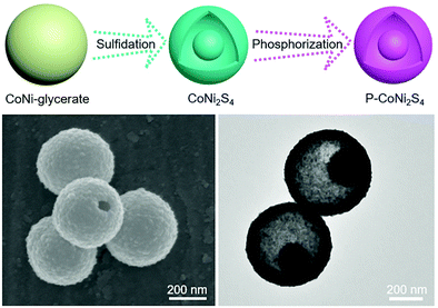 | ||
| Fig. 84 Schematic presentation of the synthesis steps leading to P-CoNi2S4 YSS particles and TEM images of these particles. Reproduced with permission from ref. 1179 Copyright Wiley 2021. | ||
This selected literature search confirms that metal-nonmetal compounds bearing different nonmetal elements belong to the most promising hydrogen evolution catalysts.
7.6 Steel-based HER and OER electrocatalysts
According to the EN 10020 standard established by the European Committee for Standardisation, steel is a material in which the mass fraction of iron is greater than that of any other element present in the material and the carbon content is generally less than 2%. Mild steel is the most common form of steel due to its low price. Corrosion-resistant steel can be achieved by coating procedures, e.g., applied to mild steel,1190,1191 or by the chosen ingredients leading to so-called stainless steels.Maurer and Strauss from the Krupp company registered two patents on stainless steel in autumn 1912, which were issued in 1918.1192,1193 In the Strauss-Maurer phase diagram, three main families of nickel-chromium based steels are isolated: martensitic (low nickel and low chromium content), austenitic (higher nickel content), and ferritic (high chromium content) steels.
The first reports of electrocatalytically initiated water splitting on steel surfaces were rather fundamental research studies, concerning the kinetic study (particularly) of HER1194–1202 and OER revealing that, 40–50 years ago, water splitting was not seriously taken into consideration as a technique suitable for the production of alternative fuels. Later steel has been intensively investigated as a conductive support for OER or HER active species1203–1235,1238 as well as for OER or HER catalytic active alloys.1236 In one of the latest published articles dedicated to the exploitation of steel as a conductive substrate for HER active electrocatalysts, Jothi et al.1213 describes a very interesting approach that uses scrap stainless steel wires to construct very active hydrogen-evolving electrodes under industrial conditions.1213
However, this subsection focuses on the use of steel as a real electrocatalyst, thus presenting the catalytic active species itself. It is very difficult to distinguish between approaches that take advantage of steel just as a conductive substrate (classical substrate-layer architecture) and approaches that are based on doping the outer sphere of the steel without completely or partly destroying the role of steel to act as the active catalyst itself, i.e., ingredients of steel as well as embedded atoms or ions are both active for catalytic promotion. This topic is the subject of a recent review article.22
It is a common knowledge that untreated steels basically show reasonable OER activity1238 but quite poor HER activity1239–1241 for electrocatalytically initiated water splitting in aqueous solutions. Advanced tools were developed to unmask activity composition relationships that allow a knowledge-based tailoring of the composition and structure of the catalytically active outer sphere.1240
Studies that use steel-based materials to promote light-driven or photoelectrocatalytic hydrogen evolution are still rare.1242–1247 The electrocatalytically driven HER on (mild) steel surfaces in aqueous solution was first examined by Leach and Saunders in 19651194 and the first time that stainless steel was reported as a hydrogen-evolving electrode in an alkaline medium dates back to 1970,1195 or to 19761196 (acid) and 19771197 (neutral). These early studies lacked any kind of investigation of the HER efficiency as, for instance, determination of the long-term current–voltage behaviour or the Faraday efficiency.
Decades later Olivares-Ramirez et al.1248 compared the HER behaviour of three different steel types: 304, 316, and 430![[thin space (1/6-em)]](https://www.rsc.org/images/entities/char_2009.gif) :
:![[thin space (1/6-em)]](https://www.rsc.org/images/entities/char_2009.gif) 316 steel was the best, owing to its highest Ni content. A more detailed investigation of efficiency aspects of the HER on 316 steel surfaces was presented in 2010 by De Silva Munoz et al.:1249 equal performance was reached in phosphate solution (1 M KH2PO4) and in 25 wt% KOH solution, with the advantage of working at milder pH 4. However, the overall efficiency of untreated stainless steels for HER is rather low (η = 340 mV; j = 1.3 mA cm−2; pH 4).1249 Steel 316 samples, mechanically or chemically surface-modified, were checked for their full water-splitting capabilities in 30 wt% KOH in 2016.1250 The sum of the overpotentials for full water splitting at j = 175 mA cm−2 occurring on both sides amounted to 1270 mV for mechanically-treated steel electrodes.1250
316 steel was the best, owing to its highest Ni content. A more detailed investigation of efficiency aspects of the HER on 316 steel surfaces was presented in 2010 by De Silva Munoz et al.:1249 equal performance was reached in phosphate solution (1 M KH2PO4) and in 25 wt% KOH solution, with the advantage of working at milder pH 4. However, the overall efficiency of untreated stainless steels for HER is rather low (η = 340 mV; j = 1.3 mA cm−2; pH 4).1249 Steel 316 samples, mechanically or chemically surface-modified, were checked for their full water-splitting capabilities in 30 wt% KOH in 2016.1250 The sum of the overpotentials for full water splitting at j = 175 mA cm−2 occurring on both sides amounted to 1270 mV for mechanically-treated steel electrodes.1250
Some of the authors evaluated Ni42 steel as a potential HER electrode material for water electrolysis at pH between 0 and 14.6.1239 Electro-oxidised samples obtained after hard anodisation in 7.2 M NaOH showed superior HER properties (η = 333 mV at j = 10 mA cm−2; pH 13). However, the performance did not even come close to that of state-of-the-art, noble HER electrocatalysts.1239 In addition, a Pt counter-electrode was used, which can falsify the results, since positive potentials applied to the Pt counter-electrode (oxygen development takes place) can lead to the dissolution of Pt and consequently to its deposition on the working electrode.1251–1255 It has been shown that this is a serious problem at least for long-term polarisation experiments in strong acids.1744 As shown later in the manuscript, the drawing of OER active components from the inside of the material to the surface of the material by electrochemical measures that goes along with corrosion-engineering applied to the steel, represents one essential strategy to increase the OER activity of steels. However, the transition-metal hydroxides obtained through corrosion engineering exhibit weak surface hydrogen adsorption at alkaline conditions leading to sluggish HER kinetics1256versus noble metals electrocatalysts.1257 It is therefore reasonable to assume that the apparently naturally low activity of steel to promote HER at negative electrode potentials has its origin in the absence of adequate noble ingredients.
Therefore, without doping with known HER active ingredients, steel-based HER electrocatalysts, whose HER performance is comparable to that of the current state-of-the-art HER electrocatalysts, such as carbon-supported platinum (Pt/C),906,1258 or transition metal phosphides,1259,1260 can hardly be synthesised. Doping might be realised through addition of noble metals or, in case non-metal doping is intended, through reaction of the metal-surface with nonmetals or nonmetal-containing compounds e.g., at higher temperature.
Non-metal doping of steel, for example, nitriding, is highly established to improve mechanical properties.1261 Enhanced HER activity of 316 steel was obtained by surface modification of 316 steel upon a sulphurisation, phosphorisation, and nitridation procedures in early 2017.1262 Sulphurisation turned out to be the most effective modification procedure (η = 136 mV; j = 10 mA cm−1; 1.0 M KOH).1262 Shortly thereafter, simultaneous nitridation and phosphorisation were applied to 304-type steel mesh, leading to self-supported HER catalysts stably and efficiently supporting alkaline HER (η = 230 mV; j = 12 mA cm−1; 1 M KOH).1263 Later, mono (nitrogen)-doped anodised stainless-steel mesh exhibited slightly better activity and high stability towards HER in 1 M KOH (η = 146 mV; j = 10 mA cm−1; 1 M KOH).1264 Besides wet electrochemical approaches, a nitrogen glow discharge plasma has been found to be capable for nitrogen-doping into the surface of steel 316 and resulted in a substantial enhancement of the HER activity of 316 steel (η = 220 mV at j = 10 mA cm−2, 20 wt% KOH).1265
Also in 2017, Anantharaj1266 reported on stainless steel scrubber (AISI 434 steel) used as working electrodes directly for OER and HER electrocatalysis.
The creation of metal carbides on the surface of steel essentially serves the purpose of increasing the surface hardness. The first example of carbide-modified steel as a potential HER electrocatalyst was published in early 2019:1267 Graphene-encapsulated Fe3C nanoparticles obtained on the surface of stainless steel 316L samples (Fig. 85) exhibited substantially improved HER activity in 1.0 M KOH.
 | ||
| Fig. 85 Schematic illustration of the fabrication procedure of SS-based electrodes. Reproduced with permission from ref. 1267. Copyright Elsevier 2019. | ||
Austenitic stainless steel 304, wet-chemically treated in boiling NaNO3/NiCl2 solution followed by phosphorisation (Ni-P doped) exhibited an increased HER activity (j = 10 mA cm−2 at η = 149 mV; 1 M KOH) and were found to be stable towards HER for 25 h.1268
We mentioned the borderline cases that do not just take advantage of steel as a conductive support based on classical coating strategies (like electrodeposition, physical vapor deposition, …) and steel ingredients still take actively part in the catalysed chemical reaction but in interaction with substances applied to the steel from the outside. This latter procedure can be realised through fine doping at a low level. Ring et al.1269 found that the HER activity of a Ni42 steel electrode drastically increases when using a Pt counter electrode. Simultaneously to hydrogen evolution occurring on the Ni42 working electrode, a platinum transfer from the counter electrode to the Ni42 electrode takes place, thereby substantially improving the HER activity of the Ni42 alloy (η = 140 mV at j = 10 mA cm−2; pH 1). Upon repetitive cycling of the potential of a steel 316 electrode between −0.2 V vs. RHE and +1.4 V vs. RHE in 6.0 M NaOH, Fe/Ni-oxide species are formed on the steel electrode.1270 Decoration of the conditioned surface with low level of gold completed the surface modification procedure and resulted in an enhancement of the HER activity.
Surface engineering consisting of chemical oxidation (KOH + NaClO) and electrochemical potentiostatic resurfacing applied to AISI 304 steel resulted in enhanced HER activity (η = 550 mV; j = 200 mA cm−2; 1.0 M KOH); (Fig. 86)1271 due to Ni(OH)2 formation.
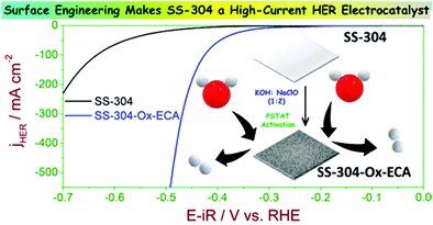 | ||
| Fig. 86 The HER activity of stainless steel 304 was enhanced in a two-step activation process comprising chemical oxidation (KOH + NaClO). Reproduced with permission from ref. 1271. Copyright American Chemical Society 2020. | ||
In a three-step procedure comprising chemical etching in HCl, electrochemical anodisation followed by thermal treatment the HER properties of steel 304 were substantially improved.1272 The etching step creates a rough surface and remove of chromium oxide. The anodisation leads to tubular iron oxide-based nanostructures and thermal annealing reduces the oxide layer.
Based on the results described above, the steel based HER electrocatalysts produced by various surface modification processes have a bright future, particularly when taking into consideration the low investment costs due to the low price and cheap mass-production.
7.6.2.1 Oxygen evolution on untreated or in situ treated Ni-Cr-based stainless steels. Around 40 years ago mild steel was pre-treated with Inco Type 123 nickel powder containing paint and afterwards sintered for 10 min in NH3 atmosphere at 870 °C:1274 substantial interdiffusion of nickel and iron occurs upon heat-treatment, leading to an OER electrocatalyst with convincing activity and durability (>1000 h) for water electrolysis in 30 wt% KOH at 80 °C (η = 200 mV at j = 100 mA cm−2). No data from electrolysis tests under normal laboratory conditions were shown, making it difficult to compare these early results with more recent ones. AISI 302 steel turned out to be an efficient and durable oxygen-evolving electrode in strong alkaline environment (η ≈ 400 mV at j = 6.3 mA cm−2; pH 14).1275 However, changes of the morphology whilst long-term usage and characterisation of the catalytic active species/determination of the faradaic efficiency were not shown. A study that is rather dedicated to unmask the mechanism of the layer formation on steel 430, 304 and 316 than with determining the ability to split water was presented by Abreu et al. in 2006.1276
The use of AISI 316L stainless steel as a simple, stable and competitive oxygen-evolution electrode in alkaline media for aqueous lithium–air batteries has been reported by Moureaux et al.1277 Long term (>3000 h) polarisation was performed in 5 M LiOH (η ≈ 500 mV) at an averaged current density of j ≈ 20 mA cm−2. The changes of the catalyst regarding, for example, crack formation and composition of the surface in operation were investigated in detail. After 500 h of activation via polarisation the steel electrode outperforms many non-PGM (and even noble) OER electrocatalysts in alkaline environments. Remarkably, the electrode shows self-healing capabilities as the “active layer” is formed in situ from the components of the bulk stainless steel. Would this layer detaches or degrades, it would reform in situ using the bulk components of the stainless steel according to the same mechanisms as for the first layer.
Three years later Sun et al. investigated the same material exploited for OER electrocatalysis in more diluted alkaline medium.1238 Without any pre-treatment, steel 316 showed satisfying OER electrocatalytic capability (at eye level with pure Nickel):1278,1279η = 370 mV at j = 10 mA cm−2 and sufficient durability (20 h of chronopotentiometry-CP. This presents the first study in which the charge-to-oxygen-conversion rate whilst OER electrocatalysis was quantified for 316 steel-based catalysts. Heterolayered Ni–Fe hydroxide/oxide nanostructures created on 316 steel upon constant current density electrolysis through dealloying plus surface oxidation.1280 Thickness, morphologies and compositions of the nanostructures did strongly depend on the electrolysis time. Under optimised preparation conditions, the anode proved active and stable under near-industrial electrolysis conditions (η = 380 mV; j = 400 mA cm−2; T = 348 K; 1.0 M KOH).
7.6.2.2 Oxygen evolution on ex situ treated Cr–Ni-based stainless steels. This subsection covers materials treated (activated) in a different medium from their medium of usage.
The first example of a series of studies in which steel was for the first time intentionally surface modified (without bringing heteroelements) prior to electrocatalysis in order to improve the electrocatalytic water-splitting properties was shown in 2015.1281
AISI 304 stainless steel was, upon a very straightforward surface oxidation in an air/chlorine mixture at room temperature, converted into a durable OER electrocatalyst with acceptable OER activity at pH 13 (η ≈ 260 mV at j = 1.5 mA cm−2) and pH 7 (η ≈ 500 mV at j = 0.65 mA cm−2).
X-ray photoelectron spectroscopy (XPS) analyses showed that a thin film of FeCr oxide was formed on the stainless steel treated with chlorine/air. The use of iron chromium oxide-based catalysts is not limited to water electrolysis but has received general attention for catalysis (reforming of ethylene glycol in aqueous phase,1282 pyrolysis of diesel fuel,1283 H2 formation from biomass1284). Anantharaj et al. used a combination of KOH and hypochlorite as the corroding agent and promoted the OER, enhancing NiO incorporated Fe2O3 nanocrystals whilst removing Cr on the surface.1285 This strategy substantially enhanced the OER activity of stainless steel AISI 304 (Fig. 87).
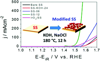 | ||
| Fig. 87 Fe2O3//NiO nanocrystals were formed on the surface of corroded AISI 304 steel and significantly improved the capability of the material to act as an OER electrode. Reproduced with permission from ref. 1285 Copyright American Chemical Society 2017. | ||
The best OER performance (η = 212 mV, j = 12 mA cm−2, 1.0 M KOH) determined for flat AISI 304 electrodes were achieved when the steel was pre-electrooxidised under harsh electrochemical conditions (j = 1.8 A cm−2 in 7.2 M NaOH).1286 The aim of this study was to mimic the composition (67 at % Ni, 33-at % Fe) of recently developed advanced- and highly active Fe–Ni-based OER electrocatalysts (Ni(2/3)Fe(1/3)) made by the Bell and Boettcher groups.104,1279
Anodic water-splitting in neutral medial is considered to be more challenging than in alkaline regime and the overpotentials obtained at pH 7 required for comparable OER current densities are substantially higher.1281 Lee et al. reported in 2017 about a 304-steel-based electrode that sufficiently supports oxygen evolution at pH 6.7–7.3;1287 after electrochemical oxidation in strong alkaline medium, the samples exhibited good performances (η = 504 mV at j = 10 mA cm−2) in a CO2-saturated bicarbonate electrolyte. Spectroscopic analyses unmasked NiOOH as the active species.
As mentioned, mild steel was investigated as potential HER electrode in the late 1960s.1194 Schäfer et al. found that pre-oxidation with Cl2/air treatment of S235 steel before performing OER electrocatalysis at pH 13 and pH 7 can significantly improve its electrocatalytic activity.1288 The OER kinetics at pH 13 were moderate (η = 347 mV at j = 2 mA cm−2); however, the one determined at pH 7 (η = 462 mV at j = 1 mA cm−2) is comparable to that of the CoPi catalyst introduced by Nocera and Kanan in 2008.1309
In an update of their initial work1277 the group around Chatenet intended to extend the developed concepts to more widely used electrolytes and reported in 2019 on ex situ (in 5.0 M LiOH or in 5 M KOH) activated steel of the same austenitic steel type 316L for use in KOH electrolyte.1454 The steel-based anodes generated this way were compared to in situ (in 5 M KOH or in 5 M LiOH) activated steel 316 L with respect to OER: (i) ex situ-activated electrodes perform comparable to in situ-activated ones (the latter being a much more time-consuming procedure), the resulting OER activities in KOH electrolytes being high compared to other non-precious metal electrocatalysts; (ii) KOH(aq) is a better electrolyte for activation than LiOH(aq), whatever the final alkaline electrolyte used. (iii) 316 L electrodes did not show significant degradation in performance and surface over a few 100 h of OER operation, which should be highlighted given the very large current densities experienced (a few 100s of mA cm−2).
Very often electro-activation of austenitic stainless steel was carried out in strong alkaline media upon applying relatively high current densities whereas the OER properties have been checked thereafter in more diluted alkalines.1286 Very recently a group from Japan has taken a different path;1289 using 1.0 M KOH for the anodisation-based electroactivation of 316 stainless steel carried out at j = 30 mA cm−2 followed by the evaluation of the OER properties in 7 M KOH, basically done at j = 100 mA cm−2. This soft electroactivation resulted in the formation of a 50 nm thick nanofiber layer comprising Ni–Fe hydroxide (catalyst layer). However, through applying 20![[thin space (1/6-em)]](https://www.rsc.org/images/entities/char_2009.gif) 000 potential scans the outer sphere (catalyst layer) was found to be unchanged whereas an NiFe-hydroxide interlayer was formed in between substrate and catalyst layer. The overall OER efficiency was comparable to the ones usually achieved with activated austenitic stainless steels.
000 potential scans the outer sphere (catalyst layer) was found to be unchanged whereas an NiFe-hydroxide interlayer was formed in between substrate and catalyst layer. The overall OER efficiency was comparable to the ones usually achieved with activated austenitic stainless steels.
Austenitic stainless steels like AISI 316 or 304 show after long tern usage as OER electrode in alkaline media exhibit cracks on their surface1277,1287,1867 which, were more a sign of self-healing power than of limited stability.
As a catalytic active material, binary Fe–Ni systems are of great general importance (they are known Fischer-Tropsch catalysts1290); they catalyse the selective conversion of furfural to methylfuran,1291 of m-cresol to toluene1292 and have been used for the catalysis of the steam reforming reaction (tar → syngas)1293 or the partial oxidation of methane to syngas.1294
Both chemical- and electrochemical activation have been applied to a stainless steel plate.1295 The stainless steel was corroded in ammonium solution at 200 °C under pressure, resulting in reasonable activity (η = 290 mV at j = 10 mA cm−2; 1.0 M KOH) and durability. A different austenitic stainless steel, namely AISI 302 was chemically activated using peroxydisulphates leading to a uniform brown film comprising Fe(Ni)OOH with rippled sheet structure:1222 this material outperforms pure nickel (η = 300 mV at j = 10 mA cm−2; Tafel slope = 34 mV dec−1).
Selenisation was found to be a very good method to increase the OER activity of stainless steels.1229,1296,1297 When high-temperature is applied to austenitic steels, a ternary phase NiFeSe forms, i.e., Se in the nickel iron selenide directly bonds to iron through a covalent bonding, hence steel does not simply act as a conductive substrate. Recently, Xiao et al.1229 reported on 304 stainless steel with a modified surface by thermo-selenisation and subsequent acid etching (enlargement of the surface): SexNi0.75Fe0.25OOH is claimed to be the catalytic active phase showing sufficient activity (η = 293 mV; j = 500 mA cm−2; 1.0 M KOH). The number of papers dealing with noble-metal-doped steel surfaces,1269 or noble metal doped surface modified steels1298 is still rather limited. Very recently Kim et al.1298 reported on a straightforward surface modification strategy applied to stainless steel AISI 304 (Fig. 88) comprising an etching procedure followed by anodisation. A Ni–Fe oxide containing periphery with trace amounts of Ru was created that converts the steel into an effective full water splitting electrocatalyst (RuNiFe-O@SS; cell voltage of 1.83 V in 1.0 M KOH, j = 100 mA cm−2).
 | ||
| Fig. 88 Schematic of the formation mechanism of RuNiFe-O@SS electrocatalyst. Reproduced with permission from ref. 1298 Copyright RSC 2021. | ||
7.6.2.3 3D-Steel-based OER electrocatalysts. To increase the catalytic active surface per projected area, 3D steel-based electrode materials have been developed. Huang et al.1299 have chosen a quite time consuming, unusual approach; a 3D stainless steel electrode designed via CAD technique was generated via selective LASER melting of stainless steel powder (Fig. 89). The authors think that the high current densities (η = 332 mV at j = 40 mA cm−2 at pH 14) are basically due to the electrode geometry and are not solely based on the electrode material itself.
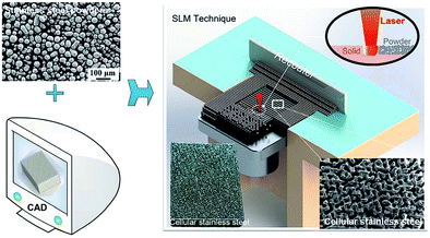 | ||
| Fig. 89 Schematic representation of the fabrication process of the CESS. Reproduced with permission from ref. 1299. Copyright RSC 2017. | ||
Assuming that 3D structures based on steel like stainless steel sponges,1300 felts,1301 mats,1296 tantangles, scrubbers1266 and different sorts of meshes1223,1228,1302 are omnipresent and are already exploited as electrodes for water electrolysis, the usefulness of a time-consuming generation is at least worthy of discussion.
Transforming rusty stainless-steel mesh into stable cathodes for batteries applications was shown.1303 Generally, surface modified steel meshes have become popular as 3D electrodes for water splitting purposes exhibiting a high current density and relatively low electrode potential (η = 230 mV at j = 20 mA cm−2)1228 outperforming Ni metal-based catalysts like Ni foam.
Fast removal of gas bubbles is a prerequisite for an efficient splitting of water into its gaseous cleavage products. It was found that Nonwoven stainless-steel fabrics are suitable for increased gas bubble escape rate during the water electrolysis process.1210
In an update of their initial work Schäfer et al. applied a phosporisation procedure to S235 steel1304 capable to convert the starting material into a quite active and stable OER electrocatalyst (η = 326 mV at j = 10 mA cm−2; 1 M KOH). Recently-published studies focused either on increasing the OER efficiency or on further increasing the long-term stability of the steel-based anode with respect to oxygen evolution:1296,1305 modified stainless steel (316L) fiber felt1306 through an electrooxidation-based approach ended up in Fe/Ni/Cr hydroxides/oxides exhibiting good long-term durability (550 h of chronopotentiometry at j = 100 mA cm−2; E = 1.54 V vs. RHE).
The most commonly-used strategy to activate austenitic stainless steel for better OER properties involves polarisation at positive potentials, which yields Ni-based species enrichment on the surface.1277,1286,1295 Etzold's group reported on a cathodisation-activation process carried out at potentials down to −0.6 V vs. RHE applied to stainless steel (316L) mesh in 0.1 M KOH (Fig. 90).1307 Obviously, Ni diffusion occurs through HER mediated adsorption induced surface segregation. The reduced Ni-species are then oxidised to NiOOH/Ni(OH)2 during OER, converting stainless steel mesh into an active OER electrocatalyst (η = 319 mV at j = 100 mA cm−2; 1.0 M KOH).
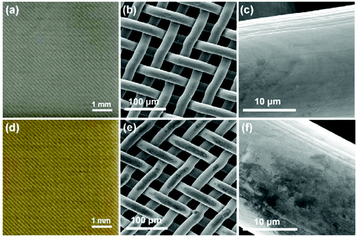 | ||
| Fig. 90 Digital photos (a and d) and SEM images (b, c, e and f) of SSM-Pristine (a–c) and SSM-Cathodisation (d–f). Reproduced with permission from ref. 1307. Copyright Elsevier 2020. | ||
Commercial 304 stainless steel mesh has recently been converted into a highly active and stable OER electrocatalyst (for more than 2 months of operation in 1.0 M KOH electrolyte).1308 The strategy comprises oxygen gas bubble formation that acts together with the release of Cr as a co-template. Conductivity and active site density are then increased by a co-sulphuration/phosphorisation step (Fig. 91).
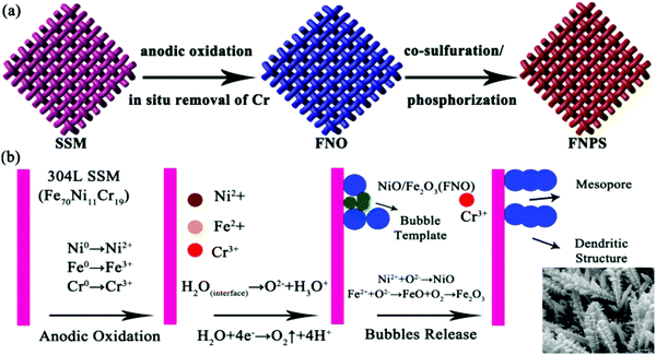 | ||
| Fig. 91 An OER-based current density of j = 100 mA cm−2 was achieved at an overpotential of η = 173 mV in 1 M KOH. Reproduced with permission from ref. 1308. Copyright Elsevier 2020. | ||
7.6.2.4 Oxygen evolution on ex situ-treated co-based steels. Cobalt-based electrode materials that actively support anodic water splitting, particularly under neutral conditions, have been known for more than ten years when Nocera and Kanan reported on the Co-Pi OER electrocatalyst.1309 Among them are Co-based cobalt borate/graphene,1310 nano-scaled cobalt oxide-based catalysts like Co3O4 nanowire arrays,1311 and graphene Co3O4 nanocomposites.1519 Some steels contain a considerable amount of cobalt.1312 Schäfer et al. reported in 2016 on the possible use of a cobalt-containing hot-work steel as an electrode for water electrolysis.40 The cobalt content on the surface of X20CoCrWMo10-9 was substantially enhanced following chromium and iron depletion whilst electro-oxidation in alkaline media. An intrinsically-grown, Co3O4-based ceramic–alloy composite with absolute benchmark OER activity at pH 7 was generated this way (η = 298 mV at j = 10 mA cm−2), significantly outperforming IrO2–RuO2,40 Co–Pi,1309 or graphene Co3O4 nanocomposites1518 in neutral electrolyte. Co3O4 is one of the most favoured compounds in inorganic materials science with advanced functionality (sensor applications,1313–1315 lithium storage,1316 supercapacitor1317). It has been investigated in depth for various applications in the broader context of heterogeneous catalysis (OER-1512 and ORR1318–1320 photocatalysis1321). It sufficiently catalyses the oxidation of CO,1322 which plays a major role in cleaning air and car emissions1323 and represents one of the most extensively investigated material in heterogeneous catalysis.
In an update, Schäfer et al. applied lithium ion doping to the Co3O4 comprising the outer sphere of the electro-oxidised tool steel X20CoCrWMo10-9.1324 XPS investigation carried out for the nonlithiated (Co-300) and lithiated samples (Co-300/Li) revealed an energy gap between the oxidation-state of the weakest and strongest oxidised cobalt ion that becomes significantly more pronounced upon lithiation. This suggests Li intercalation into the cobalt-containing layers, resulting in a valence mixture of Co(IV) and Co(II). Two distinct Li+ sites located at fixed positions within the Co-containing steel–ceramic framework can be unmasked via solid state NMR spectroscopy due to their different interaction with the paramagnetic Co(II) or Co(IV) centers (Fig. 92a). The lithiated steel exhibited substantial oxygen evolution at pH-neutral conditions close to the thermodynamic limit (Fig. 92b) and therefore outperforms all other materials compared to what is published in earlier contributions with respect to the voltage–current behaviour.
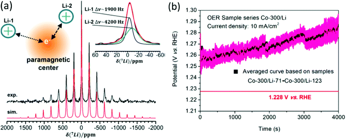 | ||
| Fig. 92 (a).7Li MAS NMR spectrum of (as-prepared) Co-300/Li recorded at 11.7 T and a MAS frequency of 25.0 kHz, showing a broad, asymmetric spinning sideband pattern characteristic of a strong electron-Li dipolar interaction. (b). Averaged chronopotentiometry curve based on 53 samples of the sample series Co-300/Li (blacksquares) with standard error bars (magenta). Reproduced with permission from ref. 1324. Copyright American Chemical Society 2018. | ||
However, the unique OER properties only last about 2 h (j = 10 mA cm−2) or 5 h (j = 5 mA cm−2) in 0.1 M KH2PO4/K2HPO4 mixtures.
7.6.2.5 Oxygen evolution on ex situ-treated steels at low pH Values. A few papers report on steel-based oxygen evolving electrodes used for water electrolysis at low pH value. As iron is the main compound of steel, it is fully understandable that creation of corrosion-resistant (protecting) layers on steel substrate is a prerequisite to successfully design reasonably-stable steel-based anodes working in acidic regimes. The first report on anodic water splitting realised by steel-based electrodes appeared in 2017:41 cobalt-based tool steel X20CoCrWMo10-9 was converted though electrooxidation in LiOH electrolyte into a reasonably active and stable OER electrode (39 μg mm−2 weight loss after 50
![[thin space (1/6-em)]](https://www.rsc.org/images/entities/char_2009.gif) 000 s of chronopotentiometry at j = 10 mA cm−2 in 0.05 M H2SO4; η = 574 mV at j = 10 mA cm−2). The OER mechanism is believed significantly impact the material removal associated with the release of oxygen from or near the surface.
000 s of chronopotentiometry at j = 10 mA cm−2 in 0.05 M H2SO4; η = 574 mV at j = 10 mA cm−2). The OER mechanism is believed significantly impact the material removal associated with the release of oxygen from or near the surface.
The so-called “oxide route” is used for materials that release oxygen out of the metal oxide-containing surface1325,1326 whereas for a different group of materials, adsorbed water molecules represent the oxygen source responsible for the OER (solution route).422
Typically, the oxide route leads to dominating dissolution process upon disruption of the surface, i.e., yields instability. Electrochemical oxidation of Ni42 steel in LiOH (sample Ni42Li205) is believed to result in the formation of a metal oxide-containing outer zone that supports solution route-based OER in acidic regime accompanied by good stability:1327 stable overpotentials down to 445 mV are required for j = 10 mA cm−2 in 0.5 M sulphuric acid.
The first example of water electrolysis of a suspension was reported in 2020;1328 the basic idea of this approach was being to completely relocate the oxygen-evolving centers from the electrode to the bulk electrolyte, which should ideally be accompanied by a substantial reduction in the weight loss of the electrode during operation. An electrolysis set up, that consisted of a Ni42 stainless steel anode and of Fe2O3 (hematite) which is suspended in high concentration in sulphuric acid and acted as the electrolyte, exhibited oxygen evolution electrocatalysis at extremely low potential (1.26 V vs. RHE; 0.5 M H2SO4, j = 30 mA cm;2Fig. 92b and 93a).
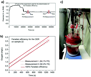 | ||
| Fig. 93 Faradaic efficiency measurements of the OER on Ni42 (sample 22) in a sulphuric acid/Fe2O3 suspension during chronopotentiometric measurements at 30 mA cm−2. Electrode area: 2 cm2. The areas where the FE measurements begin and end are highlighted. (b) Correlation of oxygen evolution (black dotted curve: measurement 1; blue dotted curve: measurement 2) with the charge passed through the electrode system (the red line corresponds to 100% faradaic efficiency). Reproduced with permission from ref. 1328. Copyright Royal Society of Chemistry 2020. | ||
The anode mass loss was negligible, and consisted exclusively of metals from the non-PGM during 100 h of operation. Experiments to clarify the mechanism suggest that Fe2O3 is converted to an Fe(II)/Fe(III) oxide species at the cathode, which is then converted back to Fe2O3, releasing molecular oxygen upon contact with the anode (Scheme 4).
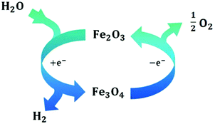 | ||
| Scheme 4 A cyclic process ensures electrocatalytically initiated splitting of water mediated through two different oxide species. Reproduced with permission from ref. 1328. Copyright Royal Society of Chemistry 2020. | ||
An almost quantitative charge to oxygen conversion (>92%) was confirmed by faradaic efficiency measurements (Fig. 93b and c).
A potential around 1.26 V vs. RHE (corresponding to η = 30 mV) for j = 30 mA cm2 determined in 0.5 M sulphuric acid is currently unparalleled is still unparalleled in water electrolysis. The already mentioned steel-based approaches for acidic water splitting require overpotentials that are least 25 times higher41,1327 than the ones derived from suspension-based approaches. Thus, for instance ternary iridium-based systems are known to be a potential candidate as an anode material that ensures reasonable activity and stability for the splitting of acids.1329 However, the overpotentials derived from these mixed oxides are 15 times higher than the one derived from the sulphuric acid/hematite electrolyte system.
To clarify why the water splitting reaction mediated by means of an electrocatalytically driven cycle with suspended iron oxide species is advantageous in comparison to classic electrolysis (clear electrolyte), the energy balances for the assumed electrochemical half-cell reactions must be drawn up. Under the assumption that HER and reduction of Fe(II) to Fe(III) simultaneously occurs the cathodic half-cell reaction can be defined as:
| Fe3+ + 3e− + 2H+ → Fe2+ + H2 | (15) |
| Fe3O4 + 2H+ → Fe2O3 + Fe2+ + 0.5O2 + H2 | (16) |
8 Research into carbon-based HER and OER electrocatalysts
This section is dedicated to carbon-based OER and HER electrocatalysts, preferably working in aqueous media, that do not contain any “bulk” metal at all, and thus go beyond the classifications of noble-metal-free or precious-metal-free.1330 Metal-free catalysts that promote water- splitting upon radiation (photocatalytic water splitting)1331 will not be discussed here. Some reviews are entirely devoted to metal-free OER and HER catalysts.1332 Generally, metal-free electrocatalysts can be seen as cost-effective and environmental-friendly.1333 Some approaches even convert natural substances like cellulose1334 or clay1381 into water-splitting catalysts. Carbon, the main component of almost all metal-free catalysts, is the most abundant element in the world and can be produced with low manufacturing costs on a large scale. Few papers describe metal-free water-splitting catalysts which are not based on carbon or in which carbon is not the main component: semiconductor-based materials can be seen as a metal-free and carbon-free catalysts, for example antimonene nanosheets, which were identified as a potential catalyst for water electrocatalysis.1335 When used as water-splitting electrodes, non-metallic electrocatalysts are often chemically modified, at least on the surface. In particular, when used as oxygen-evolving electrodes, they are converted e.g., to hydroxides or oxyhydroxides.8.1 Catalysts with a carbon skeletal structure
The development of (non-metal-containing) conducting polymers goes back to 1977, when Heeger and MacDiarmid discovered that oxidation with chlorine, bromine, or iodine increases the conductivity of vapour-made polyacetylene by a factor of 109 in the groups of.1336 The low stability and conductivity remained fundamental disadvantages of early forms of so-called inherently conducting polymers.1337,1338 The development of organic materials that are reasonably resistant, particularly towards oxidative potentials poses a special hurdle. For understandable reasons, organic materials are more suitable to act as reductive electrodes. Winther-Jensen et al.1339 reported a polymer composite composed of poly 3,4-ethylenedioxy-thio-phene (PEDOT) and a nonconductive polymer of the polyethylene glycol (PEG) family that was found to electrocatalyse proton reduction. The PEDOT-PEG based electrocatalyst coated on porous Goretex® membrane (Fig. 94 left side) was stable towards long-term HER in 1 M H2SO4, with decent HER properties: j = 2.5 mA cm−2 at η = 60 mV (Fig. 94 right side). However, rather weak HER efficiency was found in neutral media.1340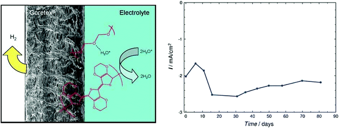 | ||
| Fig. 94 Schematic of PEDOT-based HER electrode (left side). Long-term performance of PEDOT–PEG on Goretex/Au in 1 M H2SO4 under N2 at −0.35 V vs. SCE. Reproduced with permission from ref. 1339. Copyright 2010 Wiley. | ||
Recent studies showed that nitrogen-doped or nitrogen and B or S or P-codoped carbon nanomaterials (nanotubes, graphene) can be alternative to PGM materials for ORR1341–1345 and HER1346 exhibiting an activity at least comparable to that of some traditional metal-based catalysts like Mo- or Ni-based systems.1347,1348
These results are in stark contrast to the ones reported so far: ORR and OER electrocatalysts were based on metal oxides, and the conductive substrate consisted of carbon-based materials at best.1349
The work based on (N(5)-ethlyflavinium ion Et-Fl+) published by Mirzakulova et al.1350 presents the first example of water oxidation electrocatalysis on a metal-free catalyst. Although the OER activity shown is weak, the work has opened a new category of water oxidation electrocatalysts.
Carbon cloth,1351 a cheap textile characterised by high mechanical strength, low weight, flexibility and high electric conductivity, has been intensively investigated as a conductive substrate to support various electrocatalysts for HER,1352 OER-1353,1354 or alcohol oxidation.1355 The relatively low surface area of carbon cloth made its direct exploitation as water oxidation electrodes a bit more demanding. Acidic oxidation represents one possible approach to substantially increase the overall OER activity of carbon cloth. Cheng et al. performed a chemical oxidation (pretreatment) in alkaline electrolyte yielding groups like COO− upon applying positive potentials:1356η = 477 mV was required for an OER current density of 10 mA cm−2. The OER activity of undoped carbon-based materials developed thereafter (in most cases) remained rather low despite new efforts1357 and it has been found that substantial improvement in the electrocatalytic properties of carbon-based materials is very difficult to achieve without substantial replacement of carbon atoms with heteroatoms. However, at least two recently published papers clearly demonstrate that intelligently structured materials that additionally contain oxygen-based functional groups can exhibit respectable electrocatalytic OER properties (η = 300 mV at j = 10 mA cm−2 in 1 M KOH)1358 (η = 334 mV at j = 10 mA cm−2; 0.5 M H2SO4).1359
However, irreversible carbon oxidation upon OER is thermodynamically favourable, hence unavoidable, and kinetically-accelerated for functionalised carbon surfaces1360 (e.g. graphite which is more resistant, but not corrosion-proof),1361,1362 even moreso in presence of metal-based catalysts, whatever the pH of operation.1363–1368 This issue is already extremely serious in fuel cells (both acidic and alkaline),1369 and is worse in water electrolysers as the OER electrode operates at least ca. 0.5 V higher in potential than the ORR electrode in a fuel cell. Having high-surface area (disorganised and/or functionalised) carbons will have dual consequences: larger area and possibly activity for the desired reaction (OER), but also for the parasitic one (carbon corrosion), leaving little hope to obtain a stable carbon-based OER catalyst, which explains why carbon is essentially ignored by several groups for OER electrodes, both as a catalyst support and active material.
8.2 Heteroatom doping of carbon-based OER electrocatalysts
Heteroatom doping improves the electrical conductivity and catalytic properties, in particular the OER activity of carbons. Paraknowitsch and Sakaushi review how doping with nitrogen, boron, sulphur and phosphorus influences carbons with respect to the suitability for energy applications.1370,1371While boron changes the electronic structures of carbon materials in the opposite way, but just as beneficially as nitrogen does, synergistic effects result when both dopants are used concomitantly at the same time.1370 Especially nitrogen doped carbons turned out to be astonishingly stable towards oxygen, i.e., are able to chemically activate oxygen while not reacting themselves.1372,1373
In professional circles even the designation noble carbons made the rounds for nitrogen doped carbon-based materials.1374
Nakanishi et al.1375 synthesised and investigated nitrogen-doped graphite nanomaterials (N/C) by pyrolysis of a melamine/formaldehyde polymer and nickel nitrate (Fig. 95).1375 An OER-based current density of 10 mA cm−2 was achieved at 1.61 V vs. RHE in 0.1 M KOH.
 | ||
| Fig. 95 Steps: (1) synthesis of melamine formaldehyde (MF) polymer with nickel nitrate and carbon particles; (2) pyrolysing metal-salt/MF-polymer precursor; and (3) acid leaching of the pyrolysed samples. Materials: (a) carbon particles (black dot); (b) carbon particles covered with MF polymer (yellow sphere) and nickel nitrate (green dot); a sample of pyrolysed N/C material that was not subjected to acid leaching was also prepared for a reference and was termed N/C–NiOx (c) N/C–NiOx catalyst (grey dot, NiOx); and (d) N/C catalyst. Reproduced with permission from ref. 1375. Copyright Nature Publishing. | ||
The location of the dopant (e.g., N) within the crystal (edge, corner) influences the catalytic properties for singly-doped carbon-based nanomaterials.1375 Edge-selectively phosphorus-doped graphene (G-P) showed reasonable OER activity (η = 230 mV at j = 10 mA cm−2; 1.0 M KOH); however, the study lacks long term OER stability measurements.1376
Instead of exclusively using non-metal-containing starting materials, metal-free catalysts can also be produced from a metal-containing precursor material or on a metal-containing template if the metal component is completely removed by an etching process,.1377–1383 Balogun et al. infiltrated carbon cloth with a Ni precursor, then removed the metal content, leading to the porous carbon cloth doped with N-heteroatom (NiD-PCC) without traces of Ni (Fig. 96).1377 The NiD-PCC turned out to be a reasonably active anode (η = 360 mV; j = 10 mA cm−2; 1.0 M KOH).
 | ||
| Fig. 96 Schematic illustration of the synthesis of the monolith 3D NiDPCC. Reproduced with permission from ref. 1377. Copyright 2010 Royal Society of Chemistry (RSC). | ||
In the past three years various groups studied heteroatom-doped organic frameworks as potential electrocatalysts for OER.1384–1388 Among the investigated materials are nitrogen doped ones1384–1387 as well as S,N-doped ones.1388 OER catalysis in acid is still demanding for non-noble metal (Fe, Mn, Co, Ni) containing anodes due to the combination of oxidative potentials and aggressive media which causes dissolving of the electrode material. Thus, particularly when OER at low pH value is intended, metal-free electrocatalysts could be a welcome alternative to transition metal based OER catalysts. Two recently reported metal-free OER electrocatalysts were investigated in acidic regime.1385,1386 Amino-rich carbon framework (amino-HNC), synthesised from polyaniline nanofibers, electrochemically grown on carbon paper, showed both good OER activity (η = 281 mV; j = 10 mA cm−2; 0.5 M H2SO4) but also high stability.1386 Core–shell architecture is winning strategy to improve properties of materials of different functionality and dimensionality. Carbon black//nitrogen-doped graphite core–shell structured material exhibited substantially-improved OER properties (η = 472 mV; j = 10 mA cm−2; 0.5 M H2SO4) relative to a nanocarbon-based electrode.1385
8.3 Bifunctional catalysts
To the best of the authors knowledge, the first metal-free bifunctional ORR and OER electrocatalysts were published in 2015.1389 Mesoporous carbon foam co-doped with nitrogen and phosphorous (Fig. 97) exhibits a surface area of 1.66 m2 g−1 with good ORR and OER (η = 270 mV at 5 mA cm−2 current density in 6 M KOH) performance. The most active site was identified to be N-dopant.1390,1391 Calculations revealed that besides N,P co-doping, graphene edges are crucial for their bifunctionality. Sakaushi et al. showed that a mesoporous nitrogen-doped noble carbon based on an ionic liquid can efficiently support OER and ORR in tetraethylene glycol dimethyl ether (TEGDE).1374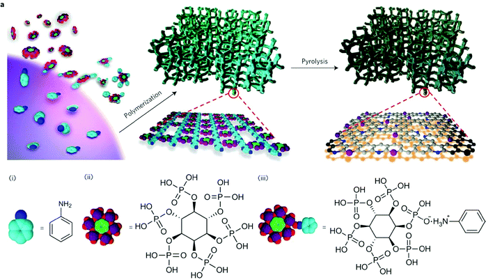 | ||
| Fig. 97 (a) Schematic illustration of the preparation process for the NPMC foams. An aniline (i)–phytic acid (ii) complex (iii) is formed (for clarity, only one of the complexed anilines is shown for an individual phytic acid), followed by oxidative polymerisation into a three-dimensional PANi hydrogel crosslinked with phytic acids. For clarity, only a piece of the two-dimensional network building block is shown in the enlarged view under the three-dimensional PANi hydrogel and only a piece of the two-dimensional NPMC network building block is shown in the enlarged view under the three-dimensional NPMC). Reproduced with permission from ref. 1389 Copyright Nature Publishing 2015. | ||
Template -based methods for the generation of bifunctional (OER/ORR) catalysts have been developed as well1380,1383e.g. by Wang et al. to generate nitrogen-doped mesoporous graphene framework (NMGF).1380 The template synthesis strategy was exploited to prepare a defective nanocarbon with B and N doped nanocarbon):1383 reasonable OER activity (η ≈ 250 mV at j = 10 mA cm−2; 1 M KOH) was achieved and its use in an air cathode resulted in low charge/discharge roundtrip efficiency and reasonable lifetime in a homemade rechargeable Zn–air battery.
Metal-free catalysts which are particularly suitable for catalysing reduction reactions, i.e. HER or ORR have been in the focus lastly.1334,1378,1379,1381,1392 A bifunctional ORR/HER electrocatalyst based on porous graphitic carbons co-doped with nitrogen and phosphorus1392 was developed, presenting the first example of a metal-free electrocatalyst suitable to promote ORR plus HER (Fig. 98), the latter with good activity (η = 210 mV at j = 30 mA cm−2).1392
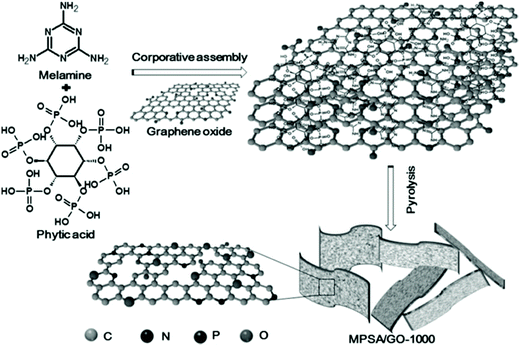 | ||
| Fig. 98 Preparation process of N,P-doped 3D porous graphitic carbon. Reproduced with permission from ref. 1392. Copyright Wiley 2016. | ||
Inexpensive and naturally-abundant cellulose nanofibrils have been converted in a catalyst with reasonable (ORR/HER) bifunctionality comprising an N,S-doped carbon nanofiber network coated with N, P-doped carbon nanoparticles.1334 With optimised composition the catalyst exhibited onset of HER at overpotentials in the 200 mV region and demonstrated good activity: j = 10 mA cm−2 at η = 331 mV (0.5 M H2SO4).
Ws,N-Doped carbon nano tubes were checked for their ORR/HER properties in the same year (2016).1378 MnOx nanorods have been used as a reactive template for generation of the carbon tubes via a wet-chemical route.1378 The annealed material delivered a bifunctional ORR/HER electrocatalyst which exhibited onset of HER (here defined as the overpotential for j = 0.2 mA cm−2) of 95 mV in 0.5 M H2SO4. The development of metal-free ORR/HER electrocatalysts continues to enjoy great popularity.1379,1381,1393 However, there is still a pronounced performance gap between the Pt-C benchmark and some of the recently developed materials.1381 Notably, the very recently developed ORR/HER material showed slightly better activity and stability towards HER.1379,1393 An interesting approach that takes (partly) usage of generally available starting material was shown by Cai et al.1393 Cigarette butts, which are mainly composed of cellulose acetate, were found to easily absorb dicyandiamide dissolved in methanol. After infiltration followed by calcination in nitrogen, porous N-doped carbon with high pyridinic N content was achieved (pyridinic N favoring hydrogen desorption). An optimised material exhibited a cathodic current density of 10 mA cm−2 at around 143 mV overpotential in 0.5 M sulphuric acid.1393 Bifunctional ORR/HER electrocatalysts that exhibit quite good HER performance in alkaline regime are rarely found. Very recently, Huang et al. evaluated N, O and P-doped hollow carbons synthesised using Co2P nanoparticles as both P source and sacrificial template; the HER activity was reasonable: j = 10 mA cm−2 at η = 290 mV in 1 M KOH.
Metal-free Bifunctional catalysts bifunctional HER/OER properties have also been targetted.1335,1394–1399 The relevance of using the same catalyst in such different conditions (strongly reductive at the negative HER electrode and strongly oxidant at the positive OER electrode) remains an open question: why would an optimised HER catalyst in terms of activity/durability would also be optimised for the OER? However, such materials will be briefly discussed below.
O,N,P-doped porous graphite carbon/oxidised carbon cloth (ONPPGC/OCC) has been recently synthesised starting from aniline, phytic acid and oxidised carbon cloth.1399 Full water splitting upon applying ONPPGC/OCC at both anode and cathode resulted in a cell voltage of Ucell = 1.66 V for j = 10 mA cm−2 in 1 M KOH. In addition, ONPPGC/OCC exhibited acceptable activity towards full water splitting in 0.5 M H2SO4: Ucell = 1.75 V at j = 10 mA cm−2.1399
Yue et al.1394 synthesised N,F-doped graphene nanosheets (NFPGNS) starting from D301 anion exchange resin, upon absorption of Na3Co(NO2)6 and KF. Acceptable HER activity (η = 330 mV; j = 10 mA cm−2; 1 M KOH) combined with acceptable OER activity was measured from steady state polarisation measurements. N-enriched polydopamine analogue was used as a carbon precursor for the generation of another OER/HER bifunctional electrocatalyst by using a spherical SiO2 template;1395 the catalyst had high pyridinic N content, and was reasonably active: j = 10 mA cm−2 at Ucell = 1.74 V; pH 14.
Pyrolysing metal-organic framework (zeolitic imidazole framework-8 ZIF-8) enables to prepare metal-free bifunctional catalysts as well. A highly N-doped (8.4 at%) carbon material with a high specific surface area was prepared that way. After cathodic polarisation treatment (CPT), N and O-containing functional groups were formed at the surface, likely explaining the satisfying electrochemical water splitting capabilities (j = 10 mA cm−2; Ucell = 1.82 V; 0.1 M KOH).1396
Commercial graphite powder exfoliated into graphene nanosheets and solvothermally treated in a steel autoclave followed by low temperature annealing exhibited astonishing electrochemical capabilities in 1.0 M KOH1398 (HER: η = 194 mV at j = 10 mA cm−2; OER: η = 304 mV at j = 10 mA cm−2).1398 However, the long-term performance and material's durability were not explored.
Recently, in a nucleophilic substitution reaction, 1,4 phenylenediamine and phlogoglucinol were reacted with cyanuricchloride in the presence of a base the resulting hybrid porous organic polymer (POP)1397 carbonised at 700 °C showed reasonable OER activity in 1.0 M KOH (j = 10 mA cm−2 at η = 430 mV) and samples calcinated at 900 °C exhibited reasonable HER activity (η = 190 mV at j = 10 mA cm−2) in 1 M sulphuric acid, obviously a result of pyridinic and pyrrolic N existing in the polymer.
As already mentioned above most of the metal-free catalysts are carbon-based ones. Exceptions are very seldom. However, profound electrochemical properties have been demonstrated for exfoliated Sb for applications in terms of energy conversion and CO2 fixation.1400–1404
Recently Ren et al. investigated antimonene nanosheets as potential bifunctional water (full water) splitting catalyst.1335 Their HER and OER performances are not satisfying: in 0.5 M KOH, η = 280 mV for jHER = 1 mA cm−2:
It would be advantageous if one and the same electrode material could support different (desired) electrode reaction like OER, ORR and HER, possibly after conversion into different optimised catalytic active species. Recently, triple functional metal-free electrocatalysts, which enable both reduction reactions in aqueous solution (HER and ORR) and oxidation reaction (OER), have been evaluated.1382,1405,1406 N,P,F-Doped graphene capable to support OER, HER and ORR were accessible by pyrolysis of polyaniline-coated graphene oxide in the presence of ammonium hexafluorophosphate.1406 Whereas single wall carbon nanotubes (SWCNT) and C60 fullerene, viewed in isolation do not show any significant catalytic activity, the combination of both compounds, i.e. a connection implemented in a suitable manner, does.1405
Buckminsterfullerene adsorbed onto SWCNT acts as an electron acceptor, ensuring an intermolecular charge transfer; this results in the formation of a triple functional (HER, OER and ORR), solely carbon-based material (Fig. 99) with reasonable activity for OER (η = 460 mV; j = 10 mA cm−2; pH 0) and HER (η = 380 mV; j = 10 mA cm−2; pH 13).
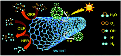 | ||
| Fig. 99 Illustration of charge-transfer process and ORR/OER/HER on C60-SWCNTs. Reproduced with permission from ref. 1405. Copyright American Chemical Society 2019. | ||
8.4 Carbon-nitrogen based catalysts with high N content
Graphitic carbon nitride (g-C3N4) is one of the oldest reported artificial polymers in the scientific literature. The use of g-C3N4 in heterogeneous catalysis began about 15 years ago in 2006.1407 It combines high nitrogen content with high chemical and thermal stability. However, g-C3N4 is known to have extremely low conductivity1408 and bulk samples show a rather low density of catalytic active sites. It was, however demonstrated that g-C3N4 nanosheets/graphene composites or g-C3N4 nanosheets/carbon nanotube composites (Fig. 100) can be OER active1409,1410 (η = 400 mV at j = 20 mA cm−2 in 0.1 M KOH),1410 (η ≈ 800 mV at j = 35 mA cm−2; 0.1 M KOH),1409 respectively. Unfortunately, long-term stability towards OER over a significant period (>10 h duration) has not been proven, and the intrinsic susceptibility for carbon to corrode in OER regime makes the authors suspicious that the catalyst is durable in operation (see above). A more complex hybrid material (S-doped carbon nitride/carbon nanotube/carbon fibre1411) was recently shown1411 with reasonable OER/HER activity in 1.0 M KOH (Ucell = 1.8 V at j = 10 mA cm−2).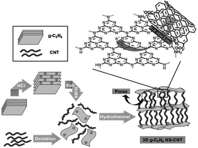 | ||
| Fig. 100 Fabrication of the 3D g-C3N4 NS-CNT porous composite. Reproduced with permission from ref. 1410. Copyright Wiley 2014. | ||
Poor contact between graphitic carbon nitride fragments and carbon and the resulting inhomogeneity may be overcome by choosing alternative routes to C3N4 based polymers, for instance based on a single carbon-nitrogen sources such as guanidine hydrochloride.1412
Doping of graphitic carbon nitride matrix with P or S or P and S was indeed found to be an effective way to manipulate electronic structure and electrochemical properties.1413,1414 In their report Lee et al. describe a theoretical structure-activity relationship in g-C3N4 for OER and ORR electrocatalysis based on an understanding of the effects of dopants considering the possible reaction pathways based on the Eley–Rideal mechanism.1415 For XY-C3N4 (where X and Y indicate the dopant and doping site on C3N4, respectively), PCSC–C3N4 (C3N4 with P and S codoped at the carbon site) shows better bifunctional performance of OER/ORR with competitive overpotentials at 0.42 and 0.27 V, respectively, compared to conventional Pt and RuO2 catalysts.
9 Concepts for electrode preparation
In water electrolysis, as in any electrochemical processes, electrocatalysts are used to increase the charge-transfer kinetics and to maximise the energy efficiency of the redox processes taking place at the interfaces. The electrochemical performance of the catalytic layers essentially depends on three factors: the catalysts’ intrinsic electrochemical activity, deployed electrochemical surface area (ESCA) and accessibility to reactants and products, the latter depending more on active layer engineering than on electrocatalyst engineering. Research into materials with optimised electrocatalytic properties therefore requires, on the one hand, to measure the intrinsic electrochemical activity of each half-cell reactions of interest and, on the other hand, nano-structuring so to maximise the surface area of the electrocatalytic particles|electrolytes interface (and the material texture to make it compatible with fast mass-transport in the active layer). Nano-structuring can be obtained using different manufacturing processes. This section describes methods and techniques to manufacture electrocatalysts and electrodes used in water electrolysis applications: electrodeposition, chemical precipitation, self-assembly, atomic layer deposition, physical vapour deposition, spray pyrolysis, ultrasonic spraying etc., all enable to tailor the materials electrocatalytic and mass-transfer properties.9.1 PEM water electrolysis
9.1.1.1 Conventional OER oxides. Noble metal oxides have been used in electrochemistry since the 1960's. Iridium oxide (IrO2) and ruthenium oxide (RuO2) have been widely employed in the chlor-alkali and chlorine industry, in the so-called dimensionally stable anodes (DSA®). They are also used as electrocatalysts at the anode of PEMWE in the form of unsupported oxide particles (IrO2, RuO2 or their solid solutions1416). They have metal-like electronic conductivity (6 × 10⁻⁵–5 × 10⁻⁵ Ω cm), a feature resulting from their electronic structure.1417 However, the risks associated with the possible formation of higher ruthenium oxides (volatility and toxicity) as well as the poorer stability of Ru and RuO2versus Ir and IrO21796 have so far led to a preference for the use of IrO2 alone in PEMWE. These oxides are synthesised by calcination of precursor salts. The synthesis of PtOx by fusion of chloroplatinic acid and sodium nitrate (300–600 °C) has been first described by R. Adams.1418 The same method can be used to synthesise IrO2 and RuO2 or their solid solutions.1419,1420 In a preferred manner, IrO2 can be synthesised from H2IrCl6·H2O mixed with NaNO3 in aqueous solution, dried, grinded, and preheated at 350 °C for 1 h. The optimum condition for IrO2 synthesis is a calcination temperature of ∼550 °C, using a mass ratio of H2IrCl6·H2O to NaNO3 of 1
![[thin space (1/6-em)]](https://www.rsc.org/images/entities/char_2009.gif) :
:![[thin space (1/6-em)]](https://www.rsc.org/images/entities/char_2009.gif) 20. The resulting IrO2 electrocatalyst has a high OER activity (90 mA cm−2 at +1.5 V vs. RHE), a high crystallinity (90%) and a large specific surface area (126 m2 g−1).1421 Unsupported IrO2 shows high electroactivity and stability (practical applications require operation in the upper range of the 50–80 kh interval). Scanning electron microscopy (SEM) images of nano structured IrO2 are shown in Fig. 101 (left). Fig. 101 (right) shows typical cyclic voltammograms (CVs) measured in situ, using the cathode of the cell as reference and counter electrode simultaneously (see Section 11). The underpotential deposition and desorption of hydrogen ad-atoms takes place at potentials lower than +0.4 V vs. RHE. At potentials above, the peaks are attributed to the Ir(III)/Ir(IV) and the Ir(IV)/Ir(V) redox couples.1422
20. The resulting IrO2 electrocatalyst has a high OER activity (90 mA cm−2 at +1.5 V vs. RHE), a high crystallinity (90%) and a large specific surface area (126 m2 g−1).1421 Unsupported IrO2 shows high electroactivity and stability (practical applications require operation in the upper range of the 50–80 kh interval). Scanning electron microscopy (SEM) images of nano structured IrO2 are shown in Fig. 101 (left). Fig. 101 (right) shows typical cyclic voltammograms (CVs) measured in situ, using the cathode of the cell as reference and counter electrode simultaneously (see Section 11). The underpotential deposition and desorption of hydrogen ad-atoms takes place at potentials lower than +0.4 V vs. RHE. At potentials above, the peaks are attributed to the Ir(III)/Ir(IV) and the Ir(IV)/Ir(V) redox couples.1422
 | ||
| Fig. 101 (left) SEM micrographs of unsupported IrO2 nanoparticles used at the anode of PEM water electrolysis cells. (right) In situ cyclic voltammograms recorded on IrO2 at the anode of a PEM water electrolysis cell, at different scan rates. Reproduced with permission from ref. 116. Copyright Elsevier 2016. | ||
Other synthesis methods have also been reported in the literature. IrO2 nanoparticles (NPs) can be synthesised using wet-chemical processes. For example, the nanoparticles can be prepared by reducing metal chlorides in ethylene glycol using PVP as a capping agent, then annealed in air at 400 °C. In that case,1423 a specific activity of up to 3.5 μA cm−2 of oxide was reported at +1.53 V vs. RHE. Rutile–IrO2 NPs were also prepared by first synthesising metallic Ir NPs in an organic solution followed by air oxidation. An intrinsic OER mass activity (the current per gram of catalyst) of 10 A goxide−1 was reported at +1.48 V vs. RHE.25
9.1.1.2 Supporting oxides. The price of iridium and the significant fluctuations in its price on the raw materials market challenges the development of the PEMWE. Efforts have been made among the scientific community to find OER alternatives to IrO2, but the task is very challenging and, to date, no real solutions to this problem have been proposed. Most research efforts focus on the reduction or Ir loadings (a factor of ten is targeted compared to 2.0 mg cm−2 loadings commonly used; ∼ 1.0 mg cm−2 is already common good practice at the industrial scale). Different approaches have been investigated and reported in the literature. Conventional OER electrocatalysts are made of micrometre sized IrO2 particles. Since 90% of the atoms of a 1 nanometre-sized cuboctahedral Ir particle are exposed at the surface, the cost issue could be alleviated by decreasing the size of the anodic electrocatalyst, assuming that the increased adsorption strength of oxygenated species on the smallest nanocrystallites does not significantly lower their intrinsic OER activity and stability. Decreasing the IrO2 crystallite size to ca. 5–15 nm is required to improve both OER mass activity and stability, while leading to a drastic reduction of the Ir content at the anode of a PEM water electrolyser.
The synthesis and use of self-standing nanometric IrO2 particles cause several problems. Their implementation at the anode of PEM water electrolysis cell can be achieved by using appropriate electron-conducting supports having (i) a large specific surface area to maximise the distribution of the nanoparticles (NPs) while preventing their agglomeration/aggregation, (ii) an optimal pore size distribution to allow easy access of reactants to the electrode and products removal from the electrode. The catalyst support should also withstand high electrochemical potentials (+1.8 to +2.1 V vs. SHE), highly acidic environment and moderate operating temperature (<80–90 °C). Carbon blacks, the usual catalyst support in PEMFCs,1424 and any types of carbonaceous structures are strongly unstable in PEMWE anodes (carbon is oxidised at potentials above +0.207 V vs. SHE) and cannot be used for that purpose. On the contrary, antimony-doped tin dioxide (ATO) substrates (aerogels or nanotubes) have more chances to meet these requirements.444,1420,1425,1426 They offer a large specific surface area and allow fast mass transport at high current density, a field in which PEM electrolysers outperform their alkaline counterparts. Moreover, their morphology is amenable to the specifications of PEM water electrolysis and their electronic conductivity can be tuned depending on the nature and concentration of dopant. This field of research is still very active, and works are in progress to improve the electrochemical stability of such materials, e.g., by tailoring their doping: while Sb-doped SnO2 type supports were shown to non-negligibly dissolve, Ta-doped or Nb-doped SnO2 supports with appropriate dopant concentrations were found more stable under acidic OER conditions.34 Scott et al. showed that the Nb2O5 addition to RuO2 was found to increase the stability of RuO2 and in some cases performance was improved. In this work, a bimetallic RuOx-Nb1−xO2 catalyst was prepared as an anode catalyst for the OER using Adams and hydrolysis methods.1427
Recently, a one-step organometallic chemical deposition (OMCD) method was reported to prepare a crystalline iridium oxide nanoparticle of 2.3 nm on antimony-doped tin oxide. In comparison to a commercial IrO2–TiO2 benchmark, the crystalline IrO2 showed a 7-fold increase in Ir mass-specific activity, as well as excellent stability.1428
The development of core@shell structures composed of a highly active and durable metal oxide (IrO2) shell, covering a cheaper and more abundant transition metal (such as cobalt, nickel, copper), is another option for reducing Ir loadings but stability problems and risks of corrosion and dissolution in PEMWE conditions have led to limited progress so far. An example is described in Fig. 102.1429
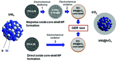 | ||
| Fig. 102 Overview of the protocol used for the synthesis of SO-IrNi@IrOx and DO-IrNi@IrOx hybrid core–shell nanoparticle catalysts. Reproduced with permission from ref. 1429. Copyright. RSC 2014. | ||
In this example, IrOx core–shell nanocatalysts were prepared using a two-step procedure:(i) synthesis of supported IrNix bimetallic nanoparticles (a previously-documented polyol process, involving 1,2-tetradecadiol as a reducing agent and oleylamine and oleic acid as capping ligands, was used to make Ni rich Ir–Ni bimetallic NPs); (ii) preparation of IrNi@IrOx hybrid core–shell catalysts. To make dealloyed metallic core–shell NPs (“D-IrNix”), the IrNix NP precursor alloys (PA-IrNix) were first electrochemically dealloyed. Selective surface-oxidation led to stepwise-oxidised (SO) metal oxide core–shell NPs “SO-IrNi@IrOx” of high mass activity (Fig. 103a). Alternatively (Fig. 103b), DO-IrNi@IrOx NPs were directly obtained by coupling dealloying/oxidation steps (“DO-IrNix”). The SO-IrNix or DO-IrNix nomenclatures emphasise the parent precursor alloy's stoichiometry, while the SO-IrNi@IrOx and DO-IrNi@IrOx nomenclatures emphasise the chemical core–shell structure. The particles thus obtained have an almost pure and nanometre-thick surface layer of IrOx. The inner central zones are more metallic and enriched in Ni. Interestingly (Fig. 103c and d), the OER activity of these core–shell particles is 3 times greater than that measured on the reference catalysts (IrO2 and RuO2). The turnover frequency (TOF) of the most active IrNi@IrOx catalysts is greatly increased. This concept of core–shell nanoparticles is quite general and can potentially be applied to the synthesis of other noble metal nanoparticles, paving the way for nanostructured PEMWE electrodes with significantly-reduced noble metal contents.
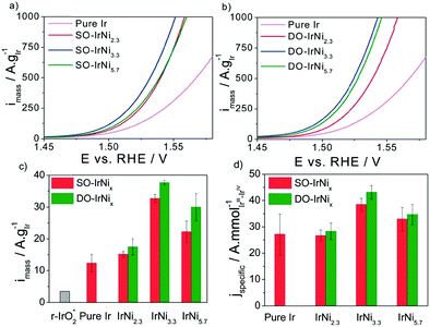 | ||
| Fig. 103 (a and b) sweep voltammetry and catalytic oxygen evolution reaction (OER) activities of stepwise oxidised (SO) IrNix and directly oxidised (DO) IrNix core–shell nanoparticles, compared to pure Ir nanoparticles. (c) Ir mass-based activities and (d) specific activities at 0.25 V overpotential. Reproduced with permission from ref. 1429. Copyright RSC 2014. | ||
 | ||
| Fig. 104 (a) Volcano plots of j0vs. M–H bond energy. (b) SEM micrographs of nano-Pt/C electrocatalysts for the HER. (c) Cyclic voltammograms measured (a) on metallic Pt in 1 M H2SO4; (b) in situ at the cathode of a PEM water electrolysis cell. Reproduced with permission from ref. 1431 Copyright Elsevier 2014. | ||
9.1.2.1 Preparation of Pt/C cathode catalyst. There are several methods to prepare Pt/C catalysts and can be categorised as chemical and physical routes (Fig. 105). The chemical routes usually involve the reduction of Pt(II) or Pt(IV) salts on high surface area carbon substrates (250–1270 m2 g−1, Cabot, Akzo Nobel etc.) by the polyol, borohydride, alcohol, and citrate reduction and metal evaporation, metal condensation, LASER ablation methods as well as electrodeposition and galvanic displacement, whilst the physical methods entails atomic layer deposition, photolytic, radiolytic, sonolytic and sonoelectrolytic reduction.1432
Different carbon substrates, different platinum precursors and different techniques can be used for the synthesis of appropriate Pt/C HER electrocatalysts, which are now commercially available (Johnson Matthey Fuel Cells, Tanaka, Umicore, HySA, etc.). Impregnation/reduction techniques are commonly used. For example, carbon particles can be soaked in Pt(NH3)2(NO3)2 solutions, evaporated to dryness and then decomposed in air (typically at 260 °C for a few hours). Colloidal suspensions of platinum can also be adsorbed on carbon,1433 and there are many techniques to perform the so: Bonnemann,1434 polyol,1435 water-in-oil1436 are typical colloidal methods that are widely employed to elaborate of low-temperature fuel cells and electrolysers catalysts (they are not specific to PEMWE catalysts). Impregnation-reduction, an also widely employed technique to prepare Pt/C for PEMFC applications1437 (in this case with an electrochemical reduction), was used to coat Pt nanoparticles onto multi-wall carbon nanotubes (MWCNT). This was achieved by using hexachloroplatinic acid (H2PtCl6) as precursor Pt salt and formaldehyde as reducing agent. After 20 minutes of impregnation, the mixture was heated to 80 °C and stirred for 3 h. Because of the lower corrosion rate of highly graphitised MWCNT and the improved contact between metal nanoparticles and carbon support, the resulting catalyst exhibited higher electrochemical stability.1438
Atomic layer deposition (ALD) of platinum has also been reported to improve the HER performance of Pt-based catalysts immobilised on functionalised Vulcan carbon. Compared to the industrial 20 wt% Pt/C catalyst, the 7.1 wt% Pt-based composite catalyst exhibited significantly-increased HER activity and stability.1439 Improvements are usually driven by research on PEMFC. Interesting results were obtained by inserting platinum nanoparticles (PtNPs) into shortened hollow graphitised carbon nanofibers (PtNP@SGNF): they achieve unprecedented electrochemical stabilisation for oxygen reduction reactions in fuel cells. Unlike commercial Pt/C electrocatalysts, the basic activity and electrochemical surface area of PtNP@SGNF remains unchanged after 50![[thin space (1/6-em)]](https://www.rsc.org/images/entities/char_2009.gif) 000 potential cycles during durability tests.1440 The stability of highly-graphitised carbon nanotubes supports (heat treatment at 2800 °C) improves the durability of platinum catalysts.
000 potential cycles during durability tests.1440 The stability of highly-graphitised carbon nanotubes supports (heat treatment at 2800 °C) improves the durability of platinum catalysts.
Another approach reported in the literature is to deposit reduced amounts of platinum on cheap (e.g., stainless steel) substrates. The easy contamination of working electrodes with trace amounts of platinum, when Pt counter electrodes are used in three electrode cells, is well-established. This can happen quite easily, during the evaluation of the HER electrochemical activity of non-PGM based materials. However, such experimental setup's flaw can be turned into a beneficial effect to develop highly active and stable HER electrocatalysts. This can be achieved by electrochemical etching of platinum using a platinum anode:1269 electrodeposition of platinum occurred at the surface of Ni42 steel (106a) during repeated HER CV scans in sulphuric acid (Fig. 106), Pt coming from the (desired) progressive dissolution of the Pt counter-electrode (on which OER is the dominant reaction). The HER which forms hydrogen bubbles interferes with the electro-crystallisation of platinum on Ni42 steel and this leads to porous Pt layers of large specific area. The process can be assisted by ultrasonication, which is beneficial in terms of activity and stability.
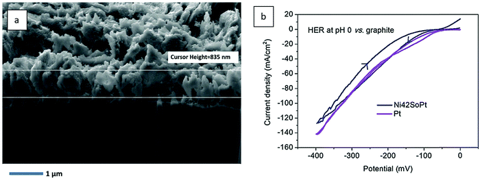 | ||
| Fig. 106 (a) SEM photograph showing the cross-section of the Ni42/Pt interface (Pt thickness ∼800–900 nm); the Pt loading is 1.8 mg cm−2. (b) comparison of the HER performances of Pt and Ni42SoPt at pH = 0. Reproduced with permission from ref. 1269. Copyright Wiley 2019. | ||
Apart from the chemical approach, it has been shown recently that Pt/C can be produced by using ultrasound in the presence and absence of electrochemistry.1432 Ultrasound produces H˙ (and OH˙) radicals in situ acting as reducing agents for the production of Pt NPs1441 and Pt/C in Nafion®.1442
9.1.2.2 Non-conventional HER catalysts. The Pt content used at PEMWE cathodes is low (<0.1–0.2 mgPt cm−2) but nevertheless contributes to the higher cost of PEMWEs compared to A(EM)WEs. In addition, platinum is extremely sensitive to the presence of impurities (organic or inorganic), which imposes severe constraints on the management of the water purity used in PEMWEs. So, the search for alternatives to platinum remains a subject of interest for the scientific community and the industry. The idea is to replace platinum with transition metals (Ni, Co, Fe), the same as those used in alkaline water electrolysis. In alkaline media, passivation of these metals prevents their dissolution. Hence, they cannot be used directly in acid media, where these metal oxides are not sufficient durable. Molecular chemistry offers some interesting solutions to such problem. Cobalt, nickel, and iron ions can be introduced in inorganic cage-like organic structures such as the clathrochelates shown on Fig. 107a.1443 In homogeneous solution, these complexes are chemically stable, and the redox properties of the central metallic center can be tuned by selecting appropriate peripherical radicals of various electro-attractive effects. With cobalt as active center, two redox waves (corresponding to CoIII/CoII and CoII/CoI redox couples) are observed (Fig. 107b). The position of the current peaks along the potential axis can be significantly shifted towards more positive potentials (to favour the HER) when peripheral radicals of increasing electro-attractive strengths are used as substituents.
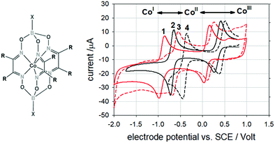 | ||
| Fig. 107 (a) General chemical formulae of cobalt clathrochelates. (b) Cyclic voltammograms recorded on three different cobalt clathrochelates in acetonitrile (10 mV s−1). Complex 1: X = n-butane and R = cyclohexane; complex 2: X = F and R = methyl group; complex 3: X = n-butane and R = phenyl group; complex 4: X = F and R = phenyl group. Reproduced with permission from ref. 1443 Copyright Wiley 2008. | ||
Such complexes and other molecular-type catalysts have been widely studied on the fundamental side (see Sections 10 and 11). They can be implemented at the cathode of PEM water electrolysis cells after adsorption at the surface of appropriate substrates such as carbonaceous compounds, commonly used to support Pt nanoparticles. The main difficulty remains despite everything the functionalisation of these catalysts on these substrates to form practical electrodes. At the laboratory scale, in order to evaluate the electroactivity of these molecular materials, simple functionalisation techniques (e.g. physisorption by impregnation,1444,1445 or by ultrasonics1446) can be used. They generally yield thin layers, which give satisfactory results but do not guarantee lifespans compatible with the targeted applications. More sophisticated functionalisation techniques are needed to produce highly active and stable monolayers. Electro-grafting is an interesting technique to use for that purpose. A two-step procedure consisting of (i) the electro-grafting of a monolayer of a diazonium derivative onto a carbonaceous substrate of interest and (ii) the chemical grafting of the compounds of interest onto the surface by simple chemical reaction, is commonly used. The technique has been used for electro-grafting of a cobalt clathrochelate containing carboxylic end-groups:1447 a monolayer-thick deposit is obtained, corresponding to very low metal loadings (in the pg cm−2 range).
9.1.2.3 Thiomolybdate compounds. In the quest for HER electrocatalysts sufficiently active and stable in acid electrolytes in PEMWE, encouraging results have been obtained with thiomolybdate compounds (molybdenum is a hundred times more abundant in the Earth crust than Pt).1448 MoS2 nanocrystallites were found active towards the hydrogen dissociation reaction in the 1980s (in the field of Hydrodesulphurisation in the oil & gas industry). Molybdenum sulphur-based catalysts were also found active for the reverse hydrogen oxidation reaction (HOR) and over the last years, for hydrogen formation in electro- or photo-catalysis HER processes. Sulphur-enriched clusters (e.g, [Mo3S13]2−), are highly stable in acidic media and have been reported to exhibit a HER activity comparable to those of PGMs such as Pt.1449 Tests and results obtained under real PEMWE conditions are scarce, but the preliminary ones reported in the literature show that replacing platinum induces a cell voltage increase by approximately 250 mV in the activation area: Ucell = 2.0 V is reached at only j = 500 mA cm−2 compared to 1.5 A.cm−2 with Pt. The compounds are chemically stable and reasonably HER electroactive (this is encouraging) but the level of performance obtained with such catalytic systems based on {MoS} is too low to consider them as good candidates to replace Pt for the HER in industrial PEMWEs.
The electrodes used in PEMWEs have the particularity of being very thin (a few microns) and porous (they must allow the gases produced to pass and allow water to access the catalytic sites). In the literature, they are rather designated by the terms “catalytic layers” or sometimes “thin-film electrodes”. This is a porous mixture essentially containing the catalyst particles and the ionomer ensuring their ionic contact with the membrane. The composition and microstructure of these CLs are critical since they dictate the overall cell efficiency, and, to a large extent, its durability. The catalytic ink can be deposited either on both sides of the membrane to form a self-standing CCM, or onto an external substrate (CCS) which is then pressed against the membrane. The term membrane electrode assembly (MEA) is also commonly used.
A large number of processes have been reported in the literature to form or coat catalyst particles directly onto (PFSA) membranes, mainly to perform laboratory tests. Electroless plating has been very popular for a long period of time. For example, hexachloroplatinic acid can be chemically reduced onto the membrane by cross-permeation of a chemical reducer such as sodium borohydride.1450 Alternatively, the membrane can be first soaked into a solution of the chemical reducer for impregnation and then into a solution of the platinum precursor salt or be soaked in an aqueous solution containing a cationic species of platinum precursor before chemical reduction. By adjusting operating conditions, thin Pt layers deeply anchored onto the membrane are obtained.1430 Such processes are less interesting for the coating of iridium-containing anodes, though electrochemical coating has also been reported in that case.1451 CCS manufacturing is widely used in fuel cell technology (Fig. 108).
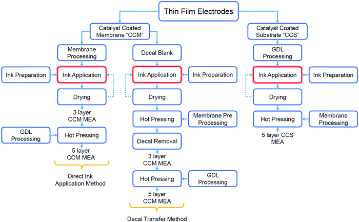 | ||
| Fig. 108 Overview of multi-steps processes used for CLs, CCMs, and MEAs manufacturing for PEM fuel cells. | ||
In early PEMFC applications, the platinum nanoparticles (used at the hydrogen anode and the oxygen cathode) were deposited on carbon GDLs to form GDEs, which are then pressed against the membrane. The need for large volume manufacturing and quality-monitoring has led to the narrowing down of available technologies for the development of automated coating processes, and particularly in the elaboration of CCMs;1452 this even more applies to PEMWE materials. In the latter case, catalyst particles (Pt/C for the cathode and IrO2 for the anode) are usually synthesised ex situ and then coated onto the membrane to form a CCM. There are basically two main options. The catalytic inks (a mixture of catalyst particles and ionomer in a solvent) are sprayed either directly onto the membrane, or onto a PTFE substrate and then transferred onto the membrane by hot pressing (so-called decal or electrode transfer method). This is performed using a catalytic ink printer, usually equipped with an ultrasonication nozzle to maintain the particle of catalyst in suspension, such as the one shown in Fig. 108. Direct spray onto the membrane is simpler (Fig. 109) but care must be taken to avoid solvent impregnation into the membrane and its detrimental swelling, favouring expansion/contraction upon the CCM elaboration process, hence possible destabilisation of the active layer (cracks, delamination). In that context, the decal method is interesting because solvent can be evaporated before transferring the electrodes to the membranes. Alternatively, magnetron-sputtering can also be used to form the particles onto a substrate.1453 Automated and continuous roll-to-roll manufacturing processes now commonly-used in PEMFC technologies are also becoming available for PEMWEs (Fig. 110).
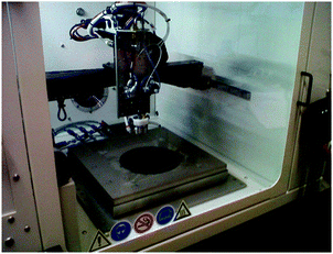 | ||
| Fig. 109 Photograph of a catalytic ink printer used to spray catalytic inks onto PFSA membranes (batch process, lab-scale). Reproduced with permission from Paris-Saclay University. | ||
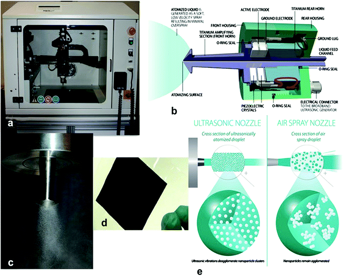 | ||
| Fig. 110 (a) Sono-Tek Ultrasonic Spray system—‘ExactaCoat’; (b) representation of the vibrating nozzle cross-section; (c) mist formation of the liquid schematic; (d) CCMs for PEMFC, DMFC, and PEMWE manufactured by the Sono-Tek system; (e) representation of nanoparticle de-agglomeration via the ultrasonic-spray method vs. the air spray method. Reproduced with permission from ref. 1432. Copyright MDPI 2019. | ||
9.2 Alkaline water electrolysis
Most of the previous techniques and materials can also be used in alkaline water electrolysis,40,1454,1455 (see Sections 3.1.1 and 5.1). However, the alkaline medium renders possible the use of non-PGM catalysts in AWE, for which the preparation methods can sharply differ. The present section highlights some of these differences, being admitted that the huge diversity of A(EM)WE catalyst/electrode materials does not enable isolating standardised strategies for their preparation/assembly.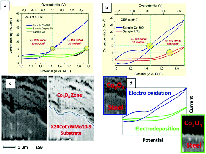 | ||
| Fig. 111 (a) Comparison of the electrochemical OER properties of sample Co-300 with sample Ir/Ru and sample Depos-30 in pH 13 (b) and pH 7. (c) SEM micrograph of a FIB machined cross section of sample Co-300. (d) A diagram represents difference between sample Co-300 (electro oxidation) and sample Depos-30 (electrodeposition) as a function of OER properties. Reproduced with permission from ref. 40. Copyright RSC 2016. | ||
Without the addition of hetero-elements or the inclusion of deposits at their surface, 316L stainless steel (SS) electrodes can be activated for the oxygen evolution reaction (OER).1277 This activation can be either in situ (surface modification during OER operation, a process that is slow and takes time) or accelerated (ex situ: alternating low/high potential steps). Both techniques allow the creation of a catalytic surface from SS bulk components under experimental conditions that are similar to those encountered in real-world applications, ensuring long-term stability and high activity of the surfaces. ex situ-Activated electrodes work similarly to in situ-activated electrodes, with higher OER activities in KOH electrolytes than other noble-metal-free electrodes. In long-term OER activity (>300 h), activated 316L electrodes are remarkably stable1454 (Fig. 112). As a result, activated SS, which is inexpensive and readily available, may be a very competitive OER material for A(EM)WEs, the materials being also compatible with operation as recharge (oxygen) electrode in metal-air batteries.1454
 | ||
| Fig. 112 Comparison of the 316L SS electrodes OER (test conducted at E = +1.75 V vs. RHE) after accelerated activation and the in situ activated 316L SS electrodes OER in 5.0 M LiOH at T = 25 °C (A). SEM of the surface of the 316L SS electrode activated (B). Reproduced with permission from ref. 1454. Copyright Elsevier 2019. | ||
Octahedral coordinated trivalent cobalt cations (CoOh3+) in metal oxyhydroxides are highly active catalytic sites for the OER; however, previous synthetic methods have limited control over these sites. Octahedral-coordinated trivalent cobalt cations (CoOH3+) in metal oxyhydroxides are highly-active catalytic sites for the OER; however, previous synthetic methods have limited control over these sites. A scalable electrodeposition method was developed in conjunction with in situ oxidation to generate amorphous Co–Fe–W trimetallic oxyhydroxides enriched in Co3+ (Fig. 113a and b). Co3+ sites comprise 72% of the Co atoms, according to X-ray absorption and computational studies. The electronic structure of Co is influenced by Fe and W in a synergistic manner, resulting in a favourable coordination environment. With an impressive TOF of 1.96 s−1 at η = 300 mV, a low Tafel slope of 32 mV dec−1, and a small activation energy of 53 kJ mol−1 in alkaline electrolyte, the Co–Fe–W oxyhydroxide exhibits high OER activity. In two-electrode water electrolysers, the catalyst directly deposited on Ni foams acts as a robust alkaline OER electrode: j = 100 mA cm−2 at η = 234 mV, 120 h durability at j = 100 mA cm−2 (Fig. 113b and c), which is ideal for practical water splitting applications.1456
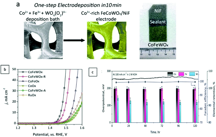 | ||
| Fig. 113 A schematic illustration of the electrodeposition of CoFeWOx on NFs (a), In 1.0 M KOH aqueous electrolyte, catalytic output of catalysts deposited on glassy carbon electrodes (GCEs) for OER in three-electron configuration (b). The electrolyser was tested for stability at 100 mA cm−2 in 1.0 M KOH electrolyte. During electrolysis, the elemental preservation of Co, Fe, and W in FeCoWOx/NiF (c). Reproduced with permission from ref. 1456. Copyright Wiley 2020. | ||
In situ-Grown 1D NiCo2S4 nanowire arrays on 3D Ni foams are effective bifunctional electrocatalysts in strongly alkaline electrolytes: binder-free self-made NiCo2S4 NW/NF electrode delivered j = 10 mA cm−2 at ηOER = 260 mV and ηHER = 210 mV in 1.0 M KOH. These good performances are explained by the material's high surface area, well-separated nanowire structure and uniform length, that was supposed to enhance mass-transport. When used in AWE, the NiCo2S4 NW/NF catalyst maintained continuous evolution of H2 and O2 at j = 10 mA cm−2 and Ucell = 1.63 V (Fig. 114), showing that overall water splitting is possible with a bifunctional electrocatalyst.1455
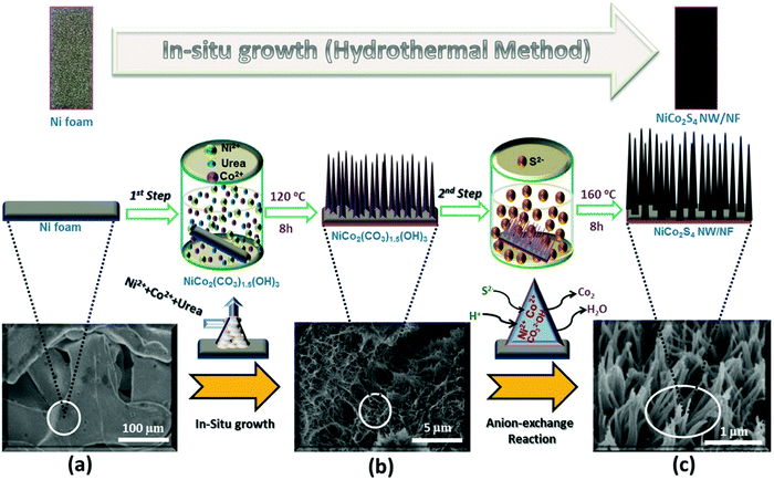 | ||
| Fig. 114 The formation of NiCo2S4 nanowire arrays on Ni foam and their morphology are depicted schematically. (a) Ni foam substrate, (b) in situ growth of NiCo2(Co3)1.5(OH)3 nanowire arrays on Ni foam (1st step), (c) hydrothermal anion exchange reaction with full growth of hierarchical NiCo2S4 nanowire arrays on Ni foam (2nd step) (a). OER polarisation curves (iR-corrected) of NiCo2S4 NW/NF, Ni3S2/NF, NiCo2O4/NF, NiCo2S4, bare Ni foam, and IrO2 with a scan rate of 10 mV s−1 (b). HER polarisation curves (iR-corrected) of NiCo2S4 NW/NF, Ni3S2/NF, NiCo2O4/NF, NiCo2S4, bare Ni foam, and Pt/C (40%) with a scan rate of 10 mV s−1. (c). Reproduced with permission from ref. 1455. Copyright Wiley 2016. | ||
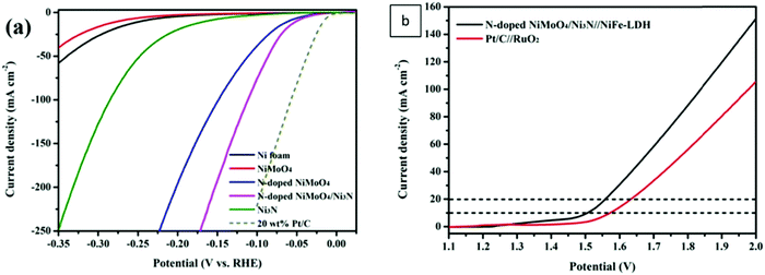 | ||
| Fig. 115 Polarisation curves of Ni foam, NiMoO4, N-doped NiMoO4, Ni3N and N-doped NiMoO4/Ni3N heterostructure (a). LSV curves of N-doped NiMoO4/Ni3N//NiFe-LDH and commercial Pt/C//RuO2 systems in 1.0 M KOH solution without iR correction (b). Reproduced with permission from ref. 1457. Copyright American Chemical Society 2020. | ||
Mo2N–Ni heterostructure on Ni foam was created by reducing NiMoO4 as a precursor during nitridation at different temperatures and for different durations. Such heterostructure between the Mo2N phase and metal Ni was shown to improve H-OH dissociation for hydrogen production and thus greatly accelerated the HER (Fig. 116). In alkaline electrolytes, the catalyst showed activity close to that of Pt surfaces, but further research is required to enhance its efficiency in acidic electrodes for large-scale applications. To account for these impressive catalytic performances, the authors put forth the vicinity between Mo2N and Ni moieties, that improves the adsorption free energy of H* at active sites, according to DFT calculations (Fig. 116d). This article showcases that simple methods can be used to develop composite electrocatalysts with transition metal and transition metal nitrides-based heterostructures, with large HER activity.1458
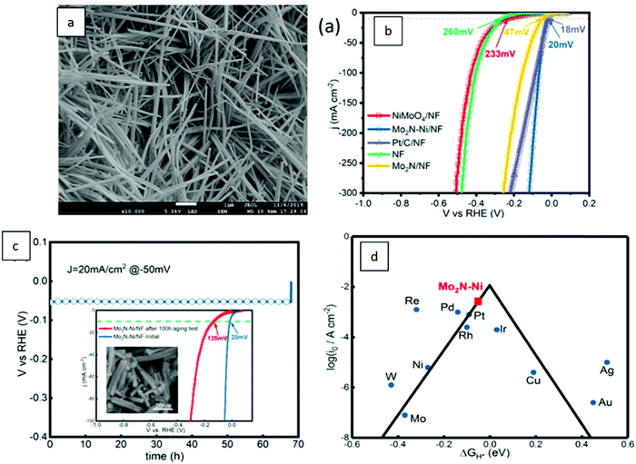 | ||
| Fig. 116 SEM image of Mo2N–Ni/NF(a). LSV curves with iR correction in 1 M KOH (b). LSV curves of Mo2N–Ni/NF before and after a 100 h aging test, and the SEM image of Mo2N–Ni/NF after a 100 h aging test (c). Volcano plot of i0 as a function of ΔGH* for Mo2N–Ni and some typical reported electrocatalysts (d). Reproduced with permission from ref. 1458. Copyright American Chemical Society 2020. | ||
10 Molecular compounds for water electrocatalysis
10.1 Molecular compounds for homogeneous- and heterogeneous water oxidation electrocatalysis
The development of molecular OER catalysts is fundamentally justified, as these are molecular species that enable water to be split via photosynthesis in nature and therefore serve as ideal models to develop artificial OER catalysts.1459–1461 The most efficient molecular water oxidation catalyst is the naturally-occurring Water Oxidising Complex (also known as the Oxygen Evolving Centre) of Photosystem II (PSII-WOC), which is completed by a collector of light energy. The CaMn4Ox core1462 is the active site of Photosystem II1463,1464 (Fig. 117). Besides this genius water oxidation core, the efficient removal of electrons (transferred to the complex through the oxidation step) via a conductive tyrosine residue coupled to the light absorbing oxidative P680 0/+ complex represents the secret of the smart oxidation process. Being inspired from Nature, the water oxidation complex of PSII has led to a couple of model catalysts for photocatalytic water splitting, referred to as bio-inspired molecular catalysts leading to so called artificial photosynthesis.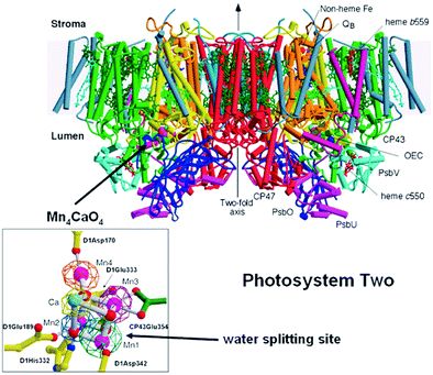 | ||
| Fig. 117 Side view of the structure of Photosystem II, the water splitting enzyme of photosynthesis. This structure was determined by X-ray crystallography. With permission from ref. 1465. Copyright AAAS 2004. | ||
Molecular systems have the advantage of being easier to study and in addition are considered to be more active per metal center.1466 This advantage is however practically attenuated by the imperfect accessibility and low density per unit volume of the active sites, thereby usually resulting into poor surface/volumetric activities versus inorganic metal-based catalysts, not to speak from the (often poor) durability of such catalytic moieties. The detailed knowledge of the composition, structure and mechanism of action of the oxygen evolving centre of photosystem II substantially helped to understand the sequential steps of water oxidation occurring through catalytically-active (inorganic) species on macroscopic electrodes and stimulated researchers in developing more efficient potential heterogeneous (solid state) water oxidation electrocatalysts. In addition, it helped improving water splitting photocatalysts, as treated extensively in review articles.1460–1470 Photocatalyst materials made up e.g., of molecular assemblies can contain additional catalytic components, often called cocatalysts, that catalyse electrochemical redox reactions (also called electrocatalyst).1471
This section deals with molecular OER and HER electrocatalysts (preferably working without sacrificial oxidant) that catalyse water splitting electrochemically, are in the dissolved state or are fixed to macroscopic electrodes (heterogenised) and do not represent a co-catalyst in photocatalyst materials. Water splitting mediated through metal organic framework (MOFs), nanoparticles (not being dissolved in the electrolyte) are at the boundary between molecular and solid-state catalysts and will not be discussed here. Water splitting supported by molecular electrocatalysts can, in principle, be assigned to both heterogeneous catalysis and homogeneous catalysis. When the catalytic active molecular species have been immobilised (heterogenised) by embedding them into a porous macroscopic electrode or by loading them onto a flat metal-oxide or semiconductor oxide-based macroscopic electrode (ITO, FTO), heterogeneous water electrocatalysis is carried out. When the molecular species capable to work as water oxidation electrocatalyst are in the dissolved state in the electrolyte and a macroscopic electrode is used for charge-transfer (namely the regeneration of the reduced form of the molecular species, which was reduced upon oxidising water molecules), homogeneous water electrolysis is performed because catalyst and substrate are in the same phase. The classification of this procedure does not change in case an additional sacrificial oxidant (e.g., Ce(IV) salts) are added. If regeneration of the molecular catalyst is ensured solely chemically by a sacrificial oxidant (see explanation below) homogeneously-catalysed water oxidation, i.e., chemical water oxidation, is carried out. When skimming a paper, it is indeed sometimes not an easy task to decide whether groups have carried out heterogeneous water catalysis or homogeneous water catalysis.1472,1473,1631
It is evident from all investigations that whenever molecular catalysts are immobilised (transition from homogeneous catalysis to heterogeneous catalysis), the electrochemical results, e.g., the OER current density to potential relationship, become significantly better.
Design rules have been postulated to develop effective, molecular-based catalysts.1474 Ligands of a successful water oxidation complex should be able to withstand strong oxidative potentials; finally, high oxidation states of the central metal need to be accessible at moderate potentials.1475
Meyer's blue dimer1476 presents the first reported homogeneous (artificial) water oxidising complex (WOC) which functions upon the exploitation of a sacrificial oxidant (Ce(IV)).
Hydrolysis of (bpy)2RuCl2 (bpy is 2,2′ bipyridine) delivers deep blue solution of (bpy)2Ru(H2O)Cl+ which upon reaction with AgNO3 is converted to the oxo-bridged Ru(III)–Ru(III) dimeric anion 1 (Fig. 118).
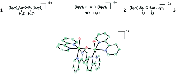 | ||
| Fig. 118 Molecular structure of cis,cis-[(bpy)2Ru(H2O)RuIIIORuIII(OH2)-(bpy)2]4+ (1).1477 Reprinted with permission from ref. 1477 Copyright 1985. American Chemical Society. | ||
Electrochemically initiated oxidation of 1via a glassy carbon electrode may lead to the Ru(IV)–Ru(III) dimeric anion species 2 through proton-coupled electron transfer (PCET) and upon additional single electron transfer steps may end in the oxo bridged Ru(V)–Ru(V) dimeric anion 3 (i.e. a total of a four-electron oxidation process) which is considered to be able to oxidise water into oxygen (OER) as shown in eqn (17). In the absence of dimer, electrolysis upon usage of a glassy carbon electrode did not lead to oxygen evolution.
 | (17) |
Cerium(IV) turned out to be a powerful one electron oxidant which in the role of the sacrificial oxidant regenerates the catalyst (reconversion of the Ru(III)–Ru(III) system to the Ru(V)–Ru(V) system) via stepwise transfer of 4 electrons each of which taken by one Ce(IV) ion.1479 Thus, it was suggested that Ru(V)–Ru(V) dimeric anion 3 act as the active part of the water oxidation catalyst (WOC), i.e., is capable to oxidise water into oxygen. The blue dimer and species derived from blue dimer are still the subject of current investigations and the elucidation of the catalysis mechanism by the blue dimer is still incomplete yet.1480–1486
The mechanism of water oxidation upon a single site ruthenium polypyridine complex carried out with sacrificial oxidising Ce(IV) was elucidated in 20081487,1488 (Fig. 119).
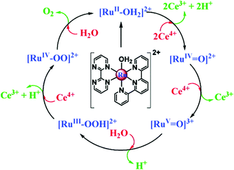 | ||
| Fig. 119 Catalytic cycle for water oxidation by single-site ruthenium-based complexes via water nucleophilic attack (WNA), in 0.1 mol L−1 de HNO3. At pH 0 beyond the steps shown an extra pathway occurs, the [RuIV–OO]2+ is further oxidised to [RuV–OO]3+, the O2 release yields [RuIII–OH]3+ starting another cycle. Reprinted with permission from ref. 1487. Copyright 2008 American Chemical Society. | ||
The catalytic cycle is based on Ce(IV) as sacrificial oxidant (Ox+), which are used in many of the subsequently developed systems in most of which they replace an electrode (as mentioned 3 in eqn (17) can be generated through conversion of 1 chemically by adding Ce(IV) instead of using an electrode) or photoelectrode. Thus, they function as a kind of helping agent for the molecular WOC (homogeneous photocatalyst)1489 (eqn (18). To ensure reasonable practicability sacrificial oxidants are not wanted and the exploitation of an electrocatalyst (indirect) or photocatalyst (direct) is preferred for solar to fuel conversion.
 | (18) |
Ru(tpy)(bpm) (OH2)2+ and Ru(tpy)(bpz) (OH2)2+ (tpy is 2,2′:6′2′′-terydine, bpm is 2,2′-bipyrimidine and bpz is 2,2′-bipyrazine) have proven to undergo hundreds of turnovers without decomposition.1487 The potential -pH diagram of both species is shown in Fig. 120.
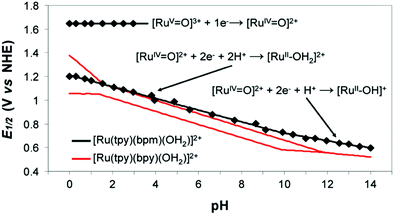 | ||
| Fig. 120 Plots of E1/2 (V vs. NHE) vs. pH for the Ru(V/IV) and Ru(IV/II) redox couples of [Ru(tpy)(bpm)(OH2)]2+ and for the Ru(IV/III) and Ru(III/II) redox couples of [Ru(tpy)(bpy)(OH2)]2+ in aqueous solution (I) 0.1 M; T) 298 K; glassy carbon working electrode). Reprinted with permission from ref. 1479 Copyright 2008. American Chemical Society. | ||
A strategy to enhance (blue dimer based) water oxidation catalysed by Ce(IV) system is to add redox mediators ([Ru (bpy)2LL]2+ (LL = bpy, bpm, bpz), exhibiting substantially faster electron-transfer kinetics when compared to Ce(IV) system.1494
Combining phosphonate surface-binding and mediator-catalyst assembly (electron-transfer mediator and catalyst function in the same molecule firmly attached to FTO or ITO electrode) ensured sustained electrolysis of 1.0 M HClO4 for more than 20 hours (Fig. 1211495).
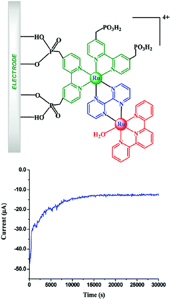 | ||
Fig. 121 Electrolysis of [(4,4′-((HO)2P(O)CH2)2bpy)2RuII(bpm)–RuII(tpy)(OH2)]4+ on FTO at 1.8 V in 1.0 M HClO4: turnovers > 8900; rate) 0.3 s−1; current density ≈ 6.7 μA cm−2; Γ ≈ 7 × 10⁻¹¹ mol cm−2; (A) 1.95 cm2. For [(4,4′-((HO)2P(O)CH2)2bpy)2RuII(bpm)RuII-(Mebimpy)(OH2)]4+ on FTO at 1.8 V in 1.0 M HClO4: turnovers >28![[thin space (1/6-em)]](https://www.rsc.org/images/entities/char_2009.gif) 000; rate) 0.6 s−1; current density ≈ 14 μA cm−2; Γ ≈ 7 × 10⁻¹¹ mol cm−2; (A) 1.95 cm2. Reprinted with permission from ref. 1495 Copyright Wiley 2009. American Chemical Society. 000; rate) 0.6 s−1; current density ≈ 14 μA cm−2; Γ ≈ 7 × 10⁻¹¹ mol cm−2; (A) 1.95 cm2. Reprinted with permission from ref. 1495 Copyright Wiley 2009. American Chemical Society. | ||
However, the current density was rather low and the overall OER efficiency based on voltage–current behaviour and upon similar materials anchored to TiO2, is not close to be competitive versus conventional alloy-based OER electrodes (not to speak from their durability).40,1454,1496 Some very recently-developed ruthenium polypyridine-based OER electrocatalysts for modification of electrodes were found to be somewhat more active and stable towards OER:1497 OER faradaic efficiency values in acid with ruthenium-polypyridine-based materials loaded on FTO or glassy carbon are in between 131498 and 50%.1499 Very rarely values around 90% have been obtained1500,1515 (Table 12), when faradaic efficiencies of e.g., alloy-based OER electrocatalysts are (determined in acids) often >80%.833,1501–1503 The catalyst performance can, in addition, be evaluated in terms of turnover numbers (TONs, defined as moles of produced product per mole of catalyst) and turnover frequencies (TOFs, defined as moles of produced product per mole of catalyst per unit of time). Ruthenium complexes are known to reach TOFs of up to 50![[thin space (1/6-em)]](https://www.rsc.org/images/entities/char_2009.gif) 000 s−1.1500
000 s−1.1500
| Compound | Faradaic efficiency (%) | Ref. |
|---|---|---|
| Poly[{Ru(H2O)(phen)}2(tpy2ph)] | 39 | 1496 |
| [Ru(H2O)(tpy)(PO(OH)2)2-bpy]]2+ | 27 | 1499 |
| poly-[Ru(bda)(4-vinylpyridine)2] | 13 | 1498 |
| [(bpy)2Ru(4-Mebpy-4′-bimpy)Ru(H2O) (tpy)]4+ | 28 | 1504 |
| [Ru(H2O)(Mebimpy)(PO3OH2)2-bpy]]2+ | 50 | 1499 |
| [RuIV(OH)(tda-κ-N3O)(pyridine)2] | 92 | 1500 |
| [RuIII(tPaO-κ-N2OPOC)(py)2]2− | 93 | 1515 |
Improvement of the activity of polypyridine-based molecular OER catalysts has occurred mainly by chosing redox-active metal matching with compatible ligands (first coordination sphere). Coordination of functional groups (weak interaction) of the ligands to the central ruthenium referred to as second coordination spheres was exploited later on to improve the catalytic activity.1505–1507 The oxidation potentials of metal complexes can be reduced by negatively charged ligands.1500,1508,1509
A binuclear ruthenium complex bearing a negatively-charged carboxylate ligand function as the WOC was generated and investigated in Sun's group1510 (Fig. 122). The same group checked ligands with different σ-donor proprieties, i.e., phosphate- and sulphonate-based bipyridine ligands for Ruthenium coordination as well:1511j = 0.7 mA cm−2 at η ≈ 500 mV was reached in bulk electrolysis experiments at in pH 1. Although this consists of poor OER activity when compared to state-of-the-art catalysts, this is an example of true homogeneous water electrocatalysis as the catalyst is dissolved in the electrolyte. Viewed in this light, activity can be considered high. Generally, it seems to be characteristic of many of these studies that great emphasis has been placed on possible reaction mechanisms.1512 However, a throughout electrochemical characterisation underpinning the OER activity in detail (inclusive long-term behaviour at reasonable current density) confirming high activity, stability and practicability is very often missing.
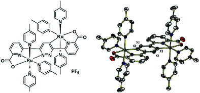 | ||
| Fig. 122 Left side. Structure of a dinuclear ruthenium complex with a negatively charged dicarboxylate ligand. Right side ORTEP view of the cation of the complex with thermal ellipsoids at the 50% probability level. H atoms are omitted for clarity. Reprinted with permission from ref. 1510. Copyright ACS 2009. | ||
The development and in-depth evaluation of ruthenium polypyridine complexes1513,1514 above all with tda based σ-donors has continued1515–1517(Fig. 123 and Table 13). However, the activity e.g., of complex 6 at pH 7 (j = 0.8 mA cm−2 at η = 600 mV) is still very weak when compared to metal (alloy)-based systems.40
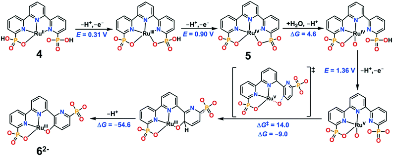 | ||
| Fig. 123 Computed Reaction Pathway at pH 7.0 for the Generation of the Catalytically Active Species [RuIII(tPaO-κ-N2OPOC)(py)2]2−, 62−, from the Precursor Complex [RuII(H2tPa-κ-N3O)(py)2], 2. Redox potentials (E) in units of volts (V) vs. NHE, and ΔGs and ΔG‡ in units of kcal mol−1. Axial pyridyl ligands are omitted for clarity. Reprinted with permission from ref. 1516. Copyright 2020 American Chemical Society. | ||
| Compound | η [μV]/j [mA cm−2] | pH | Type | Ref. |
|---|---|---|---|---|
| [RuIV(OH)(tda-K-N3O)(py2)]+ | 680/0.3 | 7 | Homogeneous | 1500 |
| [RuIII(tPaO-κ-N2OPOC)(py)2]2− | 600/0.8 | 7 | Homogeneous | 1515 |
| [Ru(tda)(4,4′-bipy]n (4,4′-bpy) | 630/30 | 7 | Heterogeneous | 1518 |
| [Ru(NH3)5Cl]2+ in Nafion | 700/0.12 | 5.4 | Heterogeneous | 1530 |
| [Ru(NH3)5Cl]2+ in Pt black | 700/3.8 | 6.8 | Heterogeneous | 1531 |
| [(NH3)5Ru(μ-O)Ru(NH3)4(μ-O)Ru(NH3)5]6+ | 670/8 | 6.8 | Heterogeneous | 1535 |
| Ir-N-Heterocyclic carbene (Ir-NHC) on graphene | 250/2.5 | 7 | Heterogeneous | 1551 |
| Ir-N-Heterocyclic carbene (Ir-NHC) on carbon nanotubes | 800/60 | 7 | Heterogeneous | 1551 |
| Fe(tpfc)Cl) on FTO | 630/0.75 | 10 | Heterogeneous | 1577 |
| Cabalt-b-octafluoro-hangman corrole | 700/0.10 | 7 | Homogeneous | 1586 |
| [NiL](ClO4)2; L = 5,5,7,12,12,14 hexamethyl-1,4,8,11 tetraazacyclotetradecane | 730/0.9 | 7 | Homogeneous | 1601 |
| NiL; L = 2,2′-((1E,1′E)-((4-chloro-5-methyl-1,2-phenylene) bis(azanylylidene)) bis(methanylylidene))diphenolate | 305/5.5 | 11 | Heterogeneous | 1616 |
| (bpy)Cu(OH)2; bpy = bipyridine | 860/6 | 13 | Homogeneous | 1620 |
| CuSO4; boron-doped diamond as WE | 1000/30 | 11 | Homogeneous | 1623 |
| [(TGG4−)CuII–OH2]2−; TGG = triglycylglycine | 700/0.5 | 11 | Homogeneous | 1524 |
Upon anchoring to multiwalled CNTs, the electrocatalytic properties of tda complexes were substantially improved (η = 630 mV; j = 30 mA cm−2, pH 7).1518 However, graphene,1519 graphene oxide,1520 carbon nanotubes1521,1522 or graphene/carbon nanotubes1523 loaded with non- noble transition metal-oxides or with ruthenium directly are, to the best of authors knowledge, not as costly and known to be very active water splitting catalysts as well.
The vast majority of the papers dealing with water splitting mediated through Ru-containing molecular systems are based on Ru-pyridine/polypyridine or Ru-ammine complexes. However, some other non-solid-state-based Ru-containing catalysts have been designed and used for water electrocatalysis.1537–1543
However, no breakthrough in terms of an acceptably high catalytic activity has yet been achieved with ruthenium-containing non solid state electrocatalysts for truly homogeneous electrocatalysis.
Os polypyridyl complexes such as Os(tpy)(bpy)(OH2)2+ are promising as the redox potentials for Os(III/II) couples and couples with higher oxidation states were found to be lower by 0.3–0.4 V relative to their Ru analogs enabling access to e.g. MV![[double bond, length as m-dash]](https://www.rsc.org/images/entities/char_e001.gif) O3+ at relatively low potentials.1544,1545
O3+ at relatively low potentials.1544,1545
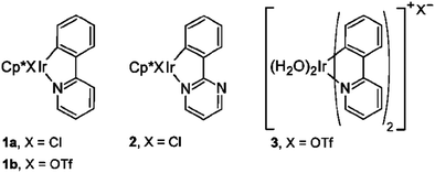 | ||
| Fig. 124 Iridium catalysts for water oxidation. Reprinted with permission from ref. 1547 Copyright 2009. American Chemical Society. | ||
In view of the considerable material costs (Ir metal, expenses for the organic ligands) the overall electrochemical activity with current densities j < 1 mA cm−2 over a wide potential range is very poor. Iridium complexes with differently stabilised triazole-derived carbene ligands for water oxidation catalysis have been evaluated upon using different sacrificial oxidants by Mazloomi et al.1548 Several other works based on homogeneous water electrocatalysis mediated through molecular iridium containing species have appeared.1549,1550 Generally, rather time-consuming approaches and considerable material costs lead to a rather low, achieved catalytic activity.1549,1550
As expected, much higher OER efficiency can be achieved if heterogeneous electrocatalysis is sought. As for instance Iridium, N-heterocyclic carbenes (NHC) immobilised via graphene, exhibited substantially better current voltage behaviour: j = 2.5 mA cm−2 at η = 250 mV1551 in neutral medium.
Carbon nanotube supported Ir-NHC complexes as water oxidation catalysts have been shown recently by Nieto et al.1552 (Fig. 125) up to j = 60 mA cm−2 at η ≈ 800 mV was reached with the best catalyst (CNT-2-Ir, investigated pH 7 (steady-state measurements).
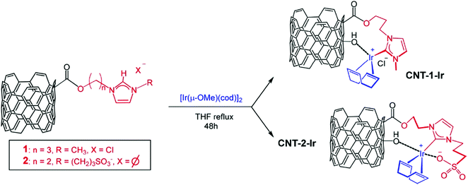 | ||
| Fig. 125 General Procedure for the Synthesis of Hybrid Carbon Nanotubes-Based IrI-NHC Catalysts. Reprinted with permission from ref. 1552. Copyright 2019. American Chemical Society. | ||
The authors believe that the publishing activity on iridium- or ruthenium-containing molecular species for electrocatalysis purposes has recently slowed, most likely due to the scarcity of the element and the recently significantly improved catalytic activity obtained with Fe, Co, or Ni-based molecules.
10.1.4.1 Manganese containing complexes. Inspired in large part by the structure of the oxygen evolving complex in Photosystem II, inorganic clusters, e.g., tetramanganese ones have been considered for water oxidation mediated by molecular systems. Due to the absence of organic ligands, they are intrinsically more stable than the ones discussed so far.
Brudvig and Crabtree reported on a dinuclear manganese complex [(OH2)Mn(tpy)(O)2Mn(tpy)(OH2)] with considerable activity for OER upon using OCl− or HSO5−.1554 However, OER can only partly be assigned to water oxidation and, in addition thermodynamically- favoured formation of MnO4− which is known to be inactive to support OER, is a serious obstacle.1468,1555
A manganese complex capable of oxidising water to oxygen in homogeneous solution when using a single-electron oxidant ([Ru(bpy)3]3+) in neutral phosphate buffer was introduced by Karlsson et al.1556
Tetramanganese (Mn4 fragment containing) clusters have preferably been exploited to drive OER under light illumination,1557 under both light illumination plus an applied potential (photoelectrocatalytic water splitting)1558 or were even found to be unable to catalyse water oxidation.1559,1560
10.1.4.2 Iron containing complexes. Iron-containing complexes have been designed and investigated as potential oxygen evolution centers as well.1561–1570 However, very often, these complexes decompose under the strongly oxidising test conditions and the formed iron ions create iron-oxide, which is the real active species promoting water oxidation with release of oxygen.1571,1572
In 2010, a series of FeIII complexes containing tetraamido macrocyclic ligands (FeIII-TAMLs) were reported as the first example of molecular iron WOCs by Bernhard and Collins.1573
A pentanuclear iron complex ([FeII4FeIII(μ3-O)(μ-L)6]3+; LH = 3,5-bis(2-pyridyl)pyrazole; Fig. 126) was designed by Okamura et al.1574 and, dissolved in an acetonitrile/water mixture, checked for its water oxidation capabilities (homogeneous water electroctatalysis).
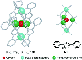 | ||
| Fig. 126 Ball-and-stick representations of the molecular structure (left) and the Fe5O core structure (right) of [FeII4FeIII(μ3-O)(μ-L)6]3+. Three penta-coordinated iron centres are bridged by an oxygen atom in μ3-fashion to form a triangle structure, and two hexa-coordinated iron centres are connected to the triangle structure by six Ls. Reprinted with permission from ref. 1574. Copyright 2016. Nature Publishing. | ||
However, only μA cm−2 were reached at a certain potential, far from solid-state-based electrodes. This group later developed a pentanuclear iron electrocatalyst with electron donating and withdrawing new ligands.1575 However, in practice reasonable current densities were not achieved.
Karim et al. investigated the electrocatalytic activity of a newly synthesised dinuclear oxo-bridged iron complex [(FeLCl)2O](FeCl4)2] (L = (2-(pyrridin-2-yl)oxazolidi-ne-4,4-diyl.1576
During bulk electrolysis in organic solvent/aqueous NaOH mixtures the catalyst showed a TON of 408 in 1 h and TOF of 0.11s−1.
A current study addressed the water-oxidising ability of mononuclear and two types of binuclear iron corroles: μ-oxo bridged and linked through β-pyrrole C atoms (Fig. 127).1577
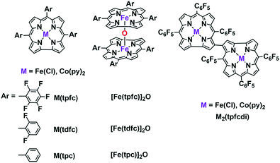 | ||
| Fig. 127 Iron and Cobalt Metallocorroles tested and compared as WOCs in the study presented by Sinha et al.1577 Reprinted with permission from ref. 1577 Copyright 2020. American Chemical Society. | ||
The electrocatalysts were heterogenised (loaded on Nafion films on FTO) and electrochemically fully characterised in pH 10 buffer solution (Fig. 128). Generally, the bimetallic species were not as efficient as their monometallic counterparts. The electrode-adsorbed iron corrole Fe(tpfc)Cl exhibited a faradaic efficiency of >95%; j ≈ 0.75 mA cm−2 at η ≈ 630 mV.
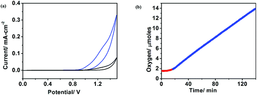 | ||
| Fig. 128 Cyclic voltammograms (V vs. Ag/AgCl) of Nafion films, loaded (blue trace) and not loaded (black trace) with Fe(tpfc)Cl, on FTO electrodes in pH 10 phosphate–KOH buffer (scan rate of 100 mV s−1; catalyst loading 1.6 nmol cm−2). (b) Evolution of oxygen before (red) and after (blue) application of a potential of 1.5 V. Reprinted with permission from ref. 1577 Copyright 2020.American Chemical Society. | ||
10.1.4.3 Cobalt containing complexes. Cobalt salts or simple cobalt complexes have been investigated as potential water oxidation catalysts.1578–1582 Water oxidation was observed on [Co4(H2O)2(PW9O34)2]10− upon adding a stable stoichiometric (sacrificial) oxidant (Fig. 129).1583
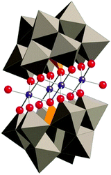 | ||
| Fig. 129 X-Ray structure of Na10[Co4(H2O)2(PW9O34)2] in combined polyhedral ([PW9O34] ligands) and ball-and-stick (Co4O16 core) notation. Co atoms are purple; O/OH2(terminal), red; PO4, orange tetrahedra; and WO6, gray octahedra. Hydrogen atoms, water molecules, and sodium cations are omitted for clarity. Reprinted with permission from ref. 1583 Copyright 2010. AAAS. | ||
A complex with a tetravalent Co centre stabilised by PCET was unknown until 2011.1584 Wasylenko et al. exploited the oxidatively stable pentadentate ligand environment of 2,6-(bis(bis-2-pyridyl)methoxy-methane)-pyridine (Py5) to form the stable coordination compound, [Co(Py5)(OH2)](ClO4)2 (Fig. 130).1585 This compound when converted to a Co(IV) species is capable to function as a (homogeneous) water oxidation catalyst in the presence of a base (Fig. 130).1585
 | ||
| Fig. 130 A structural representation of [CoII(Py5)(OH2)](ClO4)2] (left image). Pourbaix diagram for [CoII(Py5)(OH2)](ClO4)2]. Reprinted with permission from ref. 1585 Copyright 2011 RSC. | ||
Kinetic and electrochemical studies suggests that the complex acts as a molecular catalyst. The OER current density reached at certain overpotential was very low (<1 mA cm−2), limiting the practical interest of such compound.
Cobalt corroles are known to be capable to support water oxidation catalysis1577,1586–1588 (Fig. 131). Faradaic efficiency determinations confirmed in many cases quantitative charge to oxygen conversion. However, the electrochemical OER current density achieved upon applying a certain overpotential was rather weak.
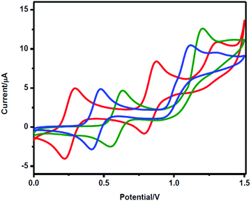 | ||
| Fig. 131 Water oxidation in the presence of Co(tpc)Py2 (red), Co(tdfc)Py2 (blue) and Co(tpfc)Py2 (green) in acetonitrile on adding 4.8% water. Reprinted with permission from ref. 1577 Copyright 2020. American Chemical Society. | ||
Among the cobalt complexes, Co(tpfc)Py2 exhibited the best OER efficiency (FE ≈ 95%) and current-potential ratio (Fig. 132). However, parallel investigations on the corresponding iron analogues uncovered that the iron corroles are better OER catalysts not only in terms of efficiency but also in stability.
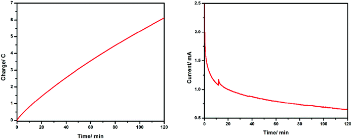 | ||
| Fig. 132 The charge vs. time and current vs. time plots obtained from chronoamperometric measurements at an applied potential of 1.5 V for two hours to the Co(tpfc)Py2 -loaded Nafion film. Reprinted with permission from ref. 1577 Copyright 2020 American Chemical Society. | ||
Molecular species containing cobalt, which can support water oxidation, have not lost any of their attractiveness as a research topic.1589–1599 Just the contrary- when inserting e.g., “cobalt-water-oxidation” into Thomson Reuters ISI Web of knowledge (Advanced search; field tag: TI = cobalt water oxidation) around 20% of the results can be assigned to cobalt containing molecules as either heterogeneous or homogeneous water oxidation catalysts.
10.1.4.4 Nickel containing complexes. Whereas solid-state Ni-based catalysts have been studied intensively in science and technology and are state of the art in many industrial systems, molecular Ni complexes did not receive that much attention for water oxidation, at least until recently.1553
The first Ni-based non-solid-state water oxidation catalyst, sandwich-type tetra nickel polyoxometalate K11Na1[Ni4(H2O)2(SiW9O34)2]·nH2O which is based on a Keggin-type building block (Fig. 133) shows the anion) was reported by Car et al.1600
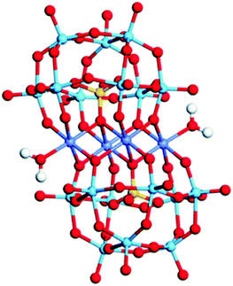 | ||
| Fig. 133 Structural model of [Ni4(H2O)2(SiW9O34)2]12− (M = Ni; W: blue, O: red; S: yellow; H: white; M: dark blue). Reprinted with permission from ref. 1600. Copyright 2012 RSC. | ||
Zhang et al. reported in 2014 about a Ni-containing complex with a cyclam-like meso ligand [Ni(meso-L](ClO4)2 with L = 5,5,7,12,12,14 hexamethyl-1,4,8,11 tetraazacyclotetradecane (Fig. 134)1601 suitable for water oxidation electrocatalysis (η = 730 mV; j = 0.9 mA cm−2).
 | ||
| Fig. 134 The structure of [Ni(meso-L)]2+. Reprinted with permission from ref. 1601. Copyright 2014 Wiley. | ||
The faradaic efficiency amounted to 97.5%. When the bulkiness of the ligands (number of methyl groups of the macrocyclic ligand) is varied, it majorly influences catalyst activity.1602–1604
Many other groups reported about nickel complexes capable to work as water oxidation catalysts upon using porphyrin-, cyclam, oxamidate-, and pyridine-based ligand frameworks.1605–1612 However, one needs to distinguish between the OER activity that originates from nickel oxide particles or nickel salts that have been formed from the nickel complex (follow-up reaction) under water electrolysis condition and the true OER activity of the corresponding nickel complex.1613
Up to now, the investigations of nickel complexes as potential electrocatalysts for water oxidation are extremely popular and many other examples were introduced throughout the last years.1614–1619 It is not a surprise that better catalytic activity (up to j = 5.5 mA cm−2; η = 305 mV; pH 11)1616 was revealed when the molecular species is immobilised on a macroscopic electrode, thus heterogenic catalysis has been performed,1614–1616 although in some case respectable efficient homogeneous electrocatalysis was shown.1619
10.1.4.5 Copper containing complexes. Elizarova et al. were the first to evaluate the OER properties of copper salts and copper containing complexes1579 (CuCl2, [Cu(bpy)2Cl2], [Cu(bpy)3Cl2]) in homogenous water catalysis at pH 10. Faradaic efficiencies in between 32% and 43% were determined, but detailed electrochemical data were not provided.
More than 30 years later three Copper Bipyridinium complexes [(bpy)Cu(μ-OH)]2X2 (X = CH3COO−, CF3SO3−, and SO42−) were checked for their water splitting capabilities by Barnett et al.1620 (Fig. 135).
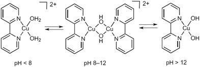 | ||
Fig. 135 The aqueous speciation of a 1![[thin space (1/6-em)]](https://www.rsc.org/images/entities/char_2009.gif) : :![[thin space (1/6-em)]](https://www.rsc.org/images/entities/char_2009.gif) 1 copper(II):bpy solution, observed by EPR. Reprinted with permission from ref. 1620. Copyright 2012 Nature Publishing. 1 copper(II):bpy solution, observed by EPR. Reprinted with permission from ref. 1620. Copyright 2012 Nature Publishing. | ||
A more detailed investigation unmasked (bpy)Cu(OH)2 as the major species present under electrocatalytic conditions at pH 13, which is consistent with earlier findings.1621,1622 The catalyst exhibited a rather moderate activity (η = 860 mV at j = 6 mA cm−2) derived from amperometry measurements.
Meyer et al. reported on simple Cu(II) salts as potential water oxidation catalysts.1623 CuSO4 dissolved in 1 M Na2CO3 is capable to reasonably promote the OER: j = 30 mA cm−2 at η = 1000 mV when boron-doped diamond is the working electrode, a decent activity for real homogenous electrocatalysis, even if the catalyst is not even close to solid-state based electrocatalysts at pH 11. A complete review of Cu-containing molecular complexes is not wanted here, but it is wise to say that substantial less research activity can be assigned to copper-based molecular OER catalysts in direct comparison1624 with their cobalt-, iron- or nickel analogues.1625–1629 Recently there have been reports about activities that are getting somewhat better.1629 However, even in the more recent publications, the activity indicated for heterogeneous catalysis remains significantly higher than that inferred (with identical species) from homogeneous catalysis.1629
10.2 Molecular compounds for homogeneous- and heterogeneous water reduction electrocatalysis
In this section, we will focus on molecular compounds based on metals abundant in the Earth's crust that supports hydrogen evolution via heterogeneous or homogeneous electrocatalysis preferably in aqueous systems. The molecular species catalysing HER may either be attached to an electrode surface to realise heterogeneous catalysis or freely diffusing in the electrolyte (homogeneous catalysis). In the latter case, the electrode solely provides electrons to the molecular catalyst. Many reviews dedicated to HER electrocatalysts have been published16,62,1630–1637 and we will concentrate on the most recent results, limiting ourselves to examples reporting efficient electrocatalysis upon molecular catalysts (Table 14).| Compound | η [mV]/j [mA cm−2] | pH | Type | Ref. |
|---|---|---|---|---|
| Nickel diphosphine complex on multiwalled carbon nanotubes (MWCNTs) | 300/4.5 | 0 | Heterogeneous | 1677 |
| [(PY5Me2)MoO(PF6)2)]; PY5Me2 = 2,6-bis(1,1-bis(2-pyridyl)ethyl)pyridine | 600/2 | 7 | Homogeneous | 1679 |
| Cu polyoxometalate complex embedded into carbon cloth | 95.4/10 | 13 | Heterogeneous | 1687 |
| [Co3(C24S12)]n (Co-PTC complex; PTC = perthiolated coronene) on carbon film | 227/10 | 0 | Heterogeneous | 1688 |
| [Co(Py3Me-Bpy)OH2] (PF6)2 | 1000/10 | 7 | Homogeneous | 1689 |
| Bpy = N,N-bis(2-pyridinylmethyl)-2,2′-bipyridine-6-methanamine | ||||
| Long chain Zr-porhyrine complex | 60/10 | 0 | Heterogeneous | 1700 |
| Ru-tannic acid complex (Ru-TA) on activated carbon cloth | 29/10 | 14 | Heterogeneous | 1701 |
| N,N,N′,N′-Tetramethyl-p-phenylenediamine intercalated between 1T′ phase MoS2 nanosheets | 150/10 | 0 | Heterogeneous | 1708 |
| Ni-Quinazoline-2(1H)-thione on glassy carbon | 250/1.4 | 0 | Heterogeneous | 1647 |
| Co(II)bis(diselenoimidodiphosphinato) | 630/10 | 14 | Heterogeneous | 1648 |
| [Co{(SePiPr2)2N}2] on Au | ||||
| Co(bpbH2)Cl2] (bpbH2: N,N′-bis(20-pyridinecarboxamide)-1,2-benzene) | 1350/1.5 | 7 | Homogeneous | 1649 |
| 1260/1.4 | 8.6 |
A detailed discussion of possible mechanistic ways to reduce protons, in the area of which either experimentally1638–1640,1662,1665,1666 or theoretically1641–1644 significant research activities have been carried out, is dispensed at this point.
Nature provides exquisite examples of catalysts in the form of hydrogenase enzymes which are based on cheaper, abundant metals like iron and nickel for proton to hydrogen catalysis and achieve considerable efficiency.1645,1646
Dinuclear iron1646 or nickel-iron complexes1646,1650–1652 represent the actives sites of the enzymes (Fig. 136). Both classes of hydrogenases can catalyse both proton reduction or hydrogen oxidation, but it is common claims that [Fe] only hydrogenases have a greater activity for the HER, while [NiFe] hydrogenases are more efficient for the conversion of hydrogen to protons (HOR). Thus, inspired by nature functional Fe-Fe hydrogenase were deliberately imitated.1653–1657 Although cobalt has no biological relevance and is significantly less abundant in the Earth crust (∼30 ppm) than Fe (6.3%) or Ni (90 ppm) it is a promising metal centre for molecular and solid state electrocatalysts. Starting more than 40 years ago proton reduction was reported for a series of NiII and Co II tetraazamacrocycles.1658–1660 Fisher and Eisenberg reported on such a cobalt-based species that catalyses hydrogen production from pure water with up to 80% faradaic yield at potentials as low as −1,36 V vs. RHE on a mercury pool electrode.1658 Cyclopentadienyl cobalt complexes were also among the earliest proton reduction catalysts examined in aqueous solutions: Grätzel et al. reported on [Co(Cp-COOH)2]+ to serve as water reduction electrocatalysts at −0.66 V vs. RHE in pH 6.5 phosphate buffer solution.1661 Cobalt complexes with glyoxime-based macrocycles have proven their ability to chemically-1662 or (decades later) electrocatalytically1663–1670 reduce protons in terms of homogeneous catalysis above all in non- aqueous solvents. Cobalt cage complexes were checked for suitability to act as HER electrocatalysts as well by groups of Grätzel and Sargeson.1661,1671 As expected, catalysis experiments resulted either in quite modest current to potential ratios in case homogeneous catalysis was performed1672 or, in case the catalytic active species have been immobilised substantial higher current density was reached at certain overpotential values.1669,1673
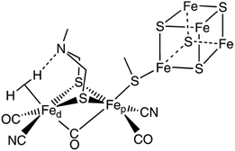 | ||
| Fig. 136 A proposed structure of the active site of the [FeFe] hydrogenase enzyme. Reprinted with permission from ref. 1646 Copyright 2007. American Chemical Society. | ||
Ni bis(phosphine) complexes known to facilitate H2 oxidation1636 have also been deeply investigated for water reduction purposes, above all in the group of Dubois.1636,1674–1676 Nickel diphosphine complexes were later on covalently attached onto multiwalled carbon nanotubes (MWCNTs) and used for heterogeneous HER electrocatalysis in 0.5 M H2SO4: they exhibited onset of hydrogen evolution at η < 50 mV and j = 4.5 mA cm−2 at η = 300 mV, derived from long-term bulk electrolysis (Fig. 137).1677 This represents an outstanding HER efficiency compared to other molecular based HER electrocatalysts. However, a commercial electrode comprising platinum loaded on a membrane still exhibited roughly two orders of magnitude higher HER-based current density at a given potential1677 (not speaking for the consequent durability of Pt electrodes for the HER).
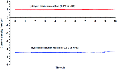 | ||
| Fig. 137 Long-run electrolysis experiments for both hydrogen evolution and oxidation carried out respectively at −0.3 and +0.3 V vs. NHE in H2SO4 (0.5 mol L−1) on a membrane electrode on which MWCNTs have been deposited and further Ni-functionalised. Reprinted with permission from ref. 1677 Copyright 2009 AAAS. | ||
Organometallic oxo derivates that show activity as a catalyst for the water reduction reaction were introduced by Parkin and Bercaw.1678 High valency metal oxo species, namely [(PY5Me2)MoO(PF6)2)] (Fig. 138), right side shows the structure of the cation) with the pentadentate ligand 2,6-bis(1,1-bis(2-pyridyl)ethyl)pyridine (PY5Me2) have been exploited as a robust HER catalyst for real homogeneous water electrocatalysis by Karunadasa et al.1679
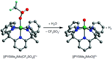 | ||
| Fig. 138 Reaction of [(PY5Me2)Mo(CF3SO3)]1+ with water to form [(PY5Me2)MoO]2+ and release H2. Reprinted with permission from ref. 1679. Copyright 2010. Nature publishing. | ||
Since the metal cores in hydrogenases are in a sulphur-rich environment, the development of complexes using macrocyclic sulphur containing ligands was considered a promising bio-inspired design principle mainly pioneered by Sellmann et al.1680–1683
Moreover, the usefulness of using S-containing ligands, which can be guessed from the catalysts found in nature, was supported by theoretical considerations: synergy between metal- and ligand-based redox activities influences catalysts performance.1684 Especially the redox activity of a dithiolato ligand and a metal centre enables a complex redox behaviour consisting of multi-step electron transfer processes between delocalised π electrons and metal d-electrons.1685 The π back donating (electron rich-) sulphur is ideal to stabilise of low-oxidation-states in the central metal, allowing the existence of different metal hydride intermediates.
However, despite considerable success in the structure modelling of hydrogenases, the new biomimics show only a low level of activity in connection with high overvoltages, so immediate optimisation prospects appear to be quite limited. In addition, the low stability of some molecular species under electrolysis condition naturally questions whether it is purposeful to develop complexes with smartly designed organic ligands if at the end degradation and metal deposition occurs in a variety of aqueous media.1686 Unless it is known exactly whether the newly designed molecular catalyst is the catalytically active species or just the precursor for the active species, it is practically impossible to assign a specific catalytic activity to the metal complex. At the end of this section, the authors would like to go into the research results that have been developed over the last 5–6 years.
Polyoxometallate of the Keggin type has proven ability to work as OER electrocatalysts.1600 Very recently a series of Keggin type polyoxometalate (POM) based Cu containing metal-organic complexes have been synthesised, immobilised upon embedding into carbon cloth and checked as molecular HER electrocatalysts for heterogeneous water catalysis.1687 The organic was varied to evaluate a possible structure-activity relationship and the highest HER performance can be observed in 0.1 M KOH: η = 95 mV at j = 10 mA cm−2. Perthiolated coronene (PTC) ligand for complexation of Co was used leading to a catalyst with the formula [Co3(C24S12)]n exhibiting unusual high conductivity (45 S cm−1). The Co-PTC catalyst deposited on carbon films showed a Tafel slope of 189 mV dec−1: η = 227 mV at j = 10 mA cm−2; pH 0.1688
As mentioned above, many metal organic complexes are prone to substantial degradation under electrocatalysis conditions. Webster et al. suggested to use soft pyridine groups to improve the stability of a low-valent CoI complex during catalysis, thereby leading to higher HER activity.1689 Real homogenously catalysed HER was shown upon [Co(Py3Me-Bpy)OH2] (PF6)2 with Bpy = N,N-bis(2-pyridinylmethyl)-2,2′-bipyridine-6-methanamine (Fig. 139) in neutral phosphate buffered medium (pH 7): j = 10 mA cm−2 at η = 1000 mV was obtained with near-quantitative charge-to hydrogen-conversion rate.
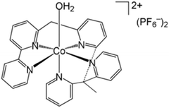 | ||
| Fig. 139 [Co(Py3Me-Bpy)OH2] (PF6)2. Reprinted with permission from ref. 1689. Copyright Wiley VCH. | ||
In several recently published articles1690–1699 brilliant theoretical or experimental investigation of catalytic pathways and characterisation of intermediates, as well as highly-advanced structure-property relationships have been shown, which might guide future catalyst design of metal organic complexes. However, convincing activity and stability at least compatible with practical application, constitutes the vast exception.
Long-chain-like zirconium porphyrin-based coordination complexes were recently successfully fabricated via a two-step strategy.:1700 promising HER properties were measured (η = 60 mV at j = 10 mA cm−2; Tafel slope of 87 mV dec−1; 0.5 M sulphuric acid).
Immobilising a Ru-tannic acid (Ru-TA) coordination complex on activated carbon cloth (ACC) was recently reported;1701 due to the tight coordination between RuIII and tannic acid in alkaline medium, the immobilised molecular Ru-TA/ACC electrocatalyst exhibits quite good HER efficiency (η = 29 mV; j = 10 mA cm2; 1.0 M KOH) which can be seen as a highly-competitive performance. Solid-state transition metal-chalcogenides like e.g. MoS2 are well known to actively support HER.1702,1703 Recent investigations show that metastable, semi-metallic 1T′ (distorted 1T) molybdenum disulphide present a particularly HER active phase.1704–1707 Kwak et al.1708 report on the hydrothermal synthesis of 1T′ phase MoS2 nanosheets that was intercalated with a series of alkylated p-phenylenediamine molecules (p-phenylenediamine (PPD), N,N-dimethyl-p-phenylenediamine (DMPD), and N,N,N′,N′-tetramethyl-p-phenylenediamine (TMPD) see Fig. 140.: intercalation goes hand-in-hand with substantial charge-transfer (0.40e, 0.73e, and 0.84e per molecule for PPD, DMPD, and TMPD), suggesting that the TMPD complex has the best HER activity. Indeed, for tetramethyl PD, one obtains η = 0.15 V at j = 10 mA cm−2 with a Tafel slope of 35 mV dec−1, underpinning the very good HER performance.
 | ||
| Fig. 140 One-step procedure of hydrothermal reaction for the synthesis of MoS2 nanosheets that were intercalated with PPD, DMPD, and TMPD. Reprinted with permission from ref. 1708. Copyright Royal Society of Chemistry. | ||
The coordinated metal centre does not present the catalytic active spot. The most active site is the nitrogen atom next to S vacancies as was shown by first principal calculations. Metal complexes in a way build a scientific bridge between the areas of homogeneous biological and heterogeneous solid-state catalysts. Challenges that scientist had to deal with include the low density of metal active sites compared to the overall size of the macromolecules and limited stability under electrolysis conditions. On the plus side we can mention the easiness regarding fine tuning and studying catalytic mechanism at a molecular level. Particularly when it comes to practical applicability, they fail in most of the relevant aspects. Classical heterogeneous catalysts lead to better apparent activity and durability, hence they are to date the only materials that can cope with practical water electrolysis.
11 Characterisation methods
Water electrolysis reactions are electrochemical reactions, and as such, any electrochemical technique has its own interest to evaluate catalyst materials, electrodes (usually in 3-electrode cell) or full electrolysis cells (2-electrode cell). However, water electrolysis reactions also convey a double specificity. Firstly, the reactions at stake, the HER at the cathode – negative electrode in a water electrolysis cell, and OER at the anode – positive electrode in a water electrolysis cell, are multiple step reactions; hence, reaction intermediates are produced/consumed, which one will need to measure/quantify, to unveil the reaction mechanisms (see Section 2), a prerequisite to the discovery of more active (and durable) electrocatalysts. Hence, a variety of physicochemical methods coupled to electrochemistry are used by the research community to assist mechanism and kinetics understanding. The most relevant, in the authors’ opinion, will be addressed hereafter. Secondly, both the HER and OER do generate gases (molecular hydrogen and molecular oxygen, respectively), which, if the rate of the reaction is sufficiently fast (a target for industrial systems), will not be purely dissolved (oversaturated) in the liquid electrolyte (water) but instead will generated bubbles.822 These bubbles will likely induce considerable difficulties in the electrochemical (and physicochemical) experiments and must therefore be considered, so that the techniques at stake are not biases by them. The present section aims at covering these aspects. Methods that are relevant to evaluate the performance of full electrolysis cells (2-electrode cells) will be addressed in Section 11.1; methods to evaluate individual electrodes (in 3-electrode cells) will be covered in Section 11.2 and finally, more advanced techniques to characterise the constitutive materials of the electrolyser (with special emphasis of the electrocatalysts, but also minorly on the membranes) will be addressed in Section 11.3. This Section 11 will introduce short-term performance characterisations and accelerated degradation tests (ADT) or accelerated stress tests (AST), whereas Section 12 will revisit most of the techniques for long-term durability assessment.11.1 Two-electrode cell characterisations of the full electrolysis cell
The most common and easiest mean to characterise a water electrolysis cell (in a non-destructive manner) is to perform measurements in the actual cell without intruding any external probe (without inserting any device in the cell for the measurement, i.e., no reference electrode for 3-electrode cell measurements). In that case, acquiring polarisation plots, i.e., the [current–cell voltage] characteristics in quasi-stationary conditions, is a widely-used methodology1709,1710 that is readily practicable for industrial cells (Fig. 141a, full symbols). The quasi-stationary conditions correspond to very slow solicitation of the system and enable to avoid any disturbance of the measured currents from capacitive effects that could be overwhelming for large-surface area electrodes (which is often the case in practical systems). The best manner to record a polarisation plot is to impose the current to the cell and measure its stable voltage (which may take a while), or to impose the cell voltage and measure the current drawn by the cell after its stabilisation. This is likely done by successive chronopotentiometric (resp. chronoamperometric) steps, whose duration should be long enough to enable the measured signal stabilisation prior any new jump to another quasi-stationary operating point. Then, longer-term chronopotentiometry (Fig. 141b) or potentiometry, enable to evaluate whether the cell performance can maintain versus time (Fig. 141b),1710 and these durability aspects will be more thoroughly addressed in Section 11.3. Polarisation plots are at the basis of any performance characterisation for studies dealing with water electrolysis, but are not always performed in a correct manner, i.e., at sufficiently slow rate to avoid capacitive effects. There are indeed numbers of studies, where authors apply the measurement by using (cyclic) linear sweep voltammetry (CV/LSV) experiments at too high potential sweep rate, thereby resulting in pronounced capacitive currents. In such conditions, it is not unusual that some authors conclude that water electrolysis is possible below the thermoneutral voltage, which makes no sense, because some of the energy is provided to the water splitting in the form of heat, that is not quantified by the simple electrochemical signals (but that would definitely be consumed in real operation, at a cost). When the polarisation plot is properly acquired, it provides information regarding the various faradaic contributions to the cell characteristics. However, this information is not directly available without extra-analyses. For example, the raw polarisation plot depends on the whole cell (the contributions from the two electrodes cannot be separated) and is non-negligibly affected by the high-frequency resistance of the cell.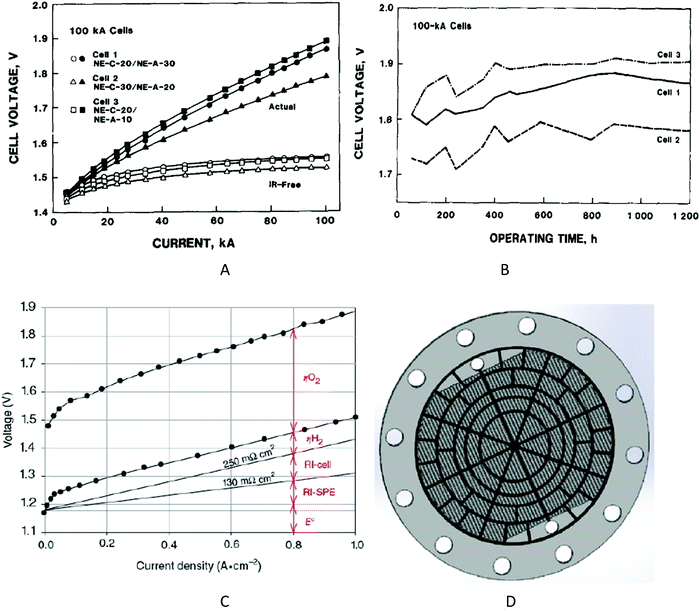 | ||
| Fig. 141 (A) Polarisation analyses of the three 100 kA Generation alkaline water electrolysers (AWE) of the Varennes experimental plant. A current of 100 kA corresponds to a current density of 0.25 A cm−2. (B) Long-term performance of the 100 kA cells of the Varennes experimental plant, monitored at a constant current of 100 kA (0.25 A cm−2). The electrolyte consists of 25% KOH at 70 °C. Reproduced from ref. with permission from Elsevier. (C) Typical PEMWE polarisation plots and corresponding individual voltage terms in the low current density range (0–1 A cm−2), for a temperature T = 90 °C and an overall pressure P = 1 bar. Reproduced from1711 with permission from Wiley-Verlag. (D) Device enabling local current density and temperature measurement during PEMWE operation. Reproduced from ref. 1712 with permission from Elsevier. | ||
High-frequency resistance (HFR) measurement is a usual complement to polarisation plots1713,1714 the best manner to measure the cell HFR is electrochemical impedance spectroscopy (EIS), though other techniques like the current interrupt are also performed on occasion, this latter technique leading to large error if the time-constant of the measuring device is not sufficiently small. The methodology of HFR measurement in a water electrolyser is no different to that regularly applied for fuel cells,242 which has been practically democratised by the team of General Motors:1715 the cell high-frequency resistance can be measured as a function of operating parameters and of core (electrode and electrolyte) materials parameters (Fig. 142a). The intercept of the high-frequency loop with the real axis is the high-frequency resistance (on Fig. 142a), its value is ca. 0.09 Ω cm2, whatever the current density applied in the range surveyed). It is thanks to the measurement of the HFR that the (so called IR-free) polarisation plot can be corrected from the IR-drop, as performed in Fig. 142a (open symbols). The HFR originates from the conductivity and thickness of the electrolyte, the potential presence of bubbles (that not only lower the conductivity of the electrolyte, but also can mask the electrodes,17,1716,1717 not speaking from the fact they can mechanically destabilise the electrodes822), the internal resistance of the electrodes and current collectors and the interfacial contact resistance between these various materials.822 Many authors have attempted to unveil these different contributions,17 like for example the interfacial resistance between the membrane and active layers, and the membrane and electrodes’ contribution to the HFR.1718 Going deeper in the analysis of EIS data, one can evaluate the proton resistance in PEMWE (or PEMFC) electrodes, associated to the hindrance of proton transport within the composite electrodes as a function of electrode parameters and/or of the cell operating parameters. This however requires that the impedance analysis is made in conditions where the electrode that is targeted is the limiting one in the assembly. One manner to do this is to have one electrode maintained under H2 (it will thus play the role of counter electrode and reference electrode, as the HER/HOR are fast reactions) and the other in N2-purged water1714,1719 (it will play the role of the working electrode). In that case, the EIS of the working electrode will give insight into its own limitations, e.g., by the proton-resistance (Fig. 142b). These methodologies, although exemplified for PEMFCs in Fig. 142 (and widely used in these systems1715,1720) can be applied to water electrolysis cells and start to be.1714,1719,1721
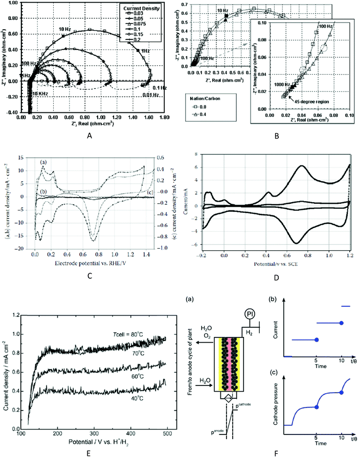 | ||
| Fig. 142 (A) Example of Nyquist plots of electrochemical impedance spectroscopy (EIS) measured on an operating unit proton exchange membrane fuel cell (PEMFC) in H2/O2 operation at several constant current densities. The membrane electrode assembly (MEA) is based on Nafion 112 Catalyst Coated Membrane with anode/cathode loading of 0.4/0.4 mgPt cm−2 and Nafion/carbon weight ratio of approximately 0.8; frequency range of 100 kHz–0.01 Hz; peak-to-peak perturbation of ±0.02 A cm−2. (B) Corresponding, complex-plane impedance for MEAs with Nafion/Carbon weight ratio of 0.8 and 0.4, respectively. Data corrected for pure resistance and inductance calculated from model. The 45° region enables to evaluate the proton resistance using a transmission line model. Reproduced from ref. 1715 with permission from the Electrochemical Society. Cyclic voltammetry of a (C) Pt/C-based cathode of PEMWE and (D) an IrO2-based anode before and after operation. Reproduced from ref. 1720 with permission from CRC press. (E) Example of H2 crossover measurement through the membrane in a PEMFC, as a function of the temperature. Reproduced from ref. 1726 with permission from Elsevier. (F) (a) Schematic view of the high-pressure water electrolyser test cell, (b) applied current profile and (c) resulting pressure profile during the experiment, with θ the characteristic time constant of the system, defined by the fraction of its permeance and its capacity. Reproduced from ref. 1727 with permission from Elsevier. | ||
In Fig. 142c, the various contributions of the polarisation plot are separated for a classical PEMWE unit cell. One naturally sees the effect of the IR-drop, both brought by the solid polymer electrolyte (RI-SPE), the other components of the cell, i.e., the electrodes, porous transport layers and interfaces between these components and the membrane (RI-cell). As the HER and OER are complex reactions, important contributions to the cell voltage depend on the overpotential associated to these reactions, noted ηH2 and ηO2 in Fig. 142c. These are connected to the activation (charge-transfer) overpotential values, i.e., the intrinsic kinetics of the reactions on the considered electrocatalysts weighted by the developed electrochemical surface area (ECSA) of the active layers, and also to the mass-transfer overpotential values, that reflect the mass-transfer hindrance to/from the catalytic sites. These individual overpotential values can hardly be directly measured in 2-electrode cell (except by electrochemical impedance spectroscopy,1722 where the authors particularly evaluate how varying the porous transport layer at the OER electrode affects the mass-transport limitation in their cell) and will be addressed in Section 11.2 related to 3-electrode cell measurements.
Chronometric measurements like those of Fig. 141b enable to evaluate the coulometry of the reactions versus time, and, by combining measurement of the gas flows, one can evaluate the faradaic efficiency (FE) of the gas production.1723 Direct measurement of the H2 content in the O2 flow exiting the anode using a proper sensor (or on-line mass spectrometry20) also enables asserting the FE.242,1724 Usually, this efficiency is close to 100% when pure water is split, a dense separator (membrane) is used, and high current densities applied (like in industrial water electrolysis). Deviation from 100% FE is likely when impure water is electrolysed (see the example of sea water electrolysis in Section 131725), when significant gas cross-over is experienced (likely in membraneless cells17,822,1723 – and this also has consequences in terms of safety of operation) and when the catalysts materials experience major degradation issues (see Section 5), but this is, again, usually not the case in practical state-of-the-art water electrolysis cells.
In conditions where one electrode of the cell plays the role of counter-electrode and reference electrode (which means it is operated under hydrated H2, see above), one can typically evaluate the response of the other electrode (which will play the role of the working electrode), e.g. by cyclic voltammetry1714,1721 This methodology, widely employed in fuel cells,83,1728 also finds applications in water electrolysers. Fig. 142c and d show typical characterisations of PEMWE electrodes,1721 where the active area can be followed in a non-destructive manner before/after PEMWE operation. The active area can simply be derived from the voltametric features of the working electrode in supporting electrolyte, i.e., in absence of faradaic reaction (which is asserted when the working electrode is maintained in inert atmosphere, like N2 or Ar-saturated water). The technique is particularly suited for PGM-based electrodes (Pt/C or IrO2-based), as PGMs have well-defined signatures in supporting electrolytes. Besides, the cyclic voltammetry in such conditions can be employed (in H2/N2 or Ar) to evaluate the hydrogen crossover through the electrolyte (usually the membrane, and specifically performed in PEMFCs)1726 (Fig. 142e); in that case, though, the potential sweep rate must be very slow, so that the capacitive current of the working electrode is decreased (it scales with the potential sweep rate) sufficiently to let the faradaic contribution (e.g. H2 oxidation at the working electrode, following H2 crossover from the counter-reference electrode compartment) overwhelm the capacitive contribution; the working electrode then gives a plateau-like current corresponding to the mass-transfer-limited HOR current, the current at the plateau depending on the amount of H2 crossing over from the counter-reference electrode compartment. It must be noted, though, that IrO2 OER electrocatalysts are not the best suited for such H2-pump measurements.1724,1729,1730 Bensman et al. reviewed techniques that can be used to measure the H2 crossover in operating water electrolysers,1727 and they proposed a refined method (the so-called current compensation technique) to measure the H2 crossover in pressurised electrolysers (Fig. 142f). The permeate flux is compensated by an electrochemical gas evolution reaction at the electrode of the high-pressure side to maintain steady-state conditions, and the required current is measured, leading to a direct quantification of the H2 crossover. Their procedure allows in situ quantification of hydrogen crossover in assembled PEMWE cells under electrolysis conditions, without the need for inert gases or external sensors. One must note that such crossover of H2 plays a non-negligible role on the durability of the water electrolyser catalysts, and in particular of its OER anode.20
When relevantly performed, 2-electrode cell operation enables measuring in a very precise manner the kinetics of water electrolysis (and fuel cell) reactions. In that case, the one electrode (counter and reference, fed with hydrated H2) shall be reasonably loaded in catalyst, not to be limiting versus the other electrode (working), which shall on the contrary be made limiting on purpose, i.e., by having “minimal” loading of catalyst. This mode of operation is valid to evaluate OER/ORR and HER/HOR catalysts, as relevantly performed by Gasteiger et al.42,84 For HER/HOR evaluation, the hydrogen pump mode was used, which enabled to measure the HER/HOR kinetics with minimal limitations from mass-transport hindrance, a usual issue in the characterisations of very fast reactions, as is the HER/HOR.
Whereas these methodologies have mostly been employed to characterise PEMFCs, there is no real limitation for their application to water electrolysis cells. Besides, although they require that the electrolyser is not in normal operation for the measurement, they are fully applicable without dismantling the cell, a great advantage in terms of non-destructive (hence fast, possibly on-site) diagnostics of the electrolysis cell.
In complement, authors recently proposed home-made designed and built segmented unit cells that enable such measurements at the local scale within a MEA.1731,1732 Segmented sensor plates equipped for local current density and temperature measurements (Fig. 141d) are also available for such measurements and have been applied to unit PEMWE.1712 These techniques were firstly proposed for fuel cell characterisations1733–1739 as recently reviewed.1740
Additional measurements are also possible at the scale of a unit water electrolysis cell (or even the stack). For example (and without being exhaustive), compression of the water electrolyser MEA can be evaluated using a pressure-sensitive film, which gives indications on whether the compression is homogeneous (or not) on the whole MEA surface,1712,1741 which has an impact on the cell operation. Using a precision Ohmmeter also enables to quantify the contact resistance between some of the cell components (e.g., the bipolar plate and the porous transport layer) as a function of the stack assembly (compaction) pressure.1741
Whatever their interest and ease of application, two-electrode cell measurement in real electrolyser cells are insufficient if one wants to access the intrinsic activity of the electrocatalysts, so as to properly evaluate the reaction overvoltage values. In that case, one needs to perform 3-electrode cell measurements.
11.2 Three-electrode cell characterisations of individual electrodes
In complement to 2-electrode cell measurements (which are possible at industrial facilities), laboratory researchers usually perform 3-electrode cell measurements, in which they independently control the potential of the working electrode (WE) and counter-electrode (CE) versus a properly chosen reference-electrode (RE). The nature and position of the RE should be optimal to enable noiseless measurements, and not bias the operation of the WE (it shall not mask the surface of the WE to avoid disturbance of the current lines, be sufficiently close of the WE to limit the Ohmic drop, and not lead to the pollution of the electrolyte, which is possible e.g., with Cl− containing references, Cl− being a poison to many electrocatalysts encountered in water electrolysis, e.g., Pt1742). By using a RE, the electrochemical signal of the WE can be isolated from that of the CE, and Ohmic-drop correction can be performed in a dynamic manner (although this can yield difficulties under bubbles evolution regime, where the conductivity of the electrolyte may non-negligibly change in operation, hence rendering awkward precise and direct Ohmic-drop correction). Three-electrode cell measurements are also compatible with experiments in which the CE compartment is separated from the working electrode (by a membrane or a glass frit), thereby limiting the influence of the CE (because it produces by-products in operation) on the behaviour of the working electrode. Nevertheless, it is always required to adopt the “proper” CE, both in terms of nature of its constitutive material, and in terms of surface area (so that the potential difference between the WE and CE is not limited by the compliance of the potentiate, which can become critical if large currents are experienced and/or if the Ohmic drop is non-negligible). The nature of the CE should be chosen to sustain the WE current (not to be counter-electrode limited) and does not pollute the electrolyte by products of its major or side reactions.1743 In that prospect, metallic CE may dissolve, hence favouring deposits at the WE surface, this phenomenon being likely when the working electrode is in reduction (e.g., under HER) and the counter electrode in oxidation (e.g., OER in competition with metal dissolution). This effect is well-known by the community and recalled in several “good practice papers”.1744,1745 It can nevertheless be used as an advantage to “activate” an electrode at minimal materials’ cost1269 (in that case using the dissolution of a Pt CE to provoke subtle deposition of Pt at the WE surface), even though plenty examples of the literature suffer such effect in an uncontrolled manner (not even evoked by their authors).Polarisation plots can be easily measured in 3-electrode cells, usually in the rotating disk electrode (RDE) configuration, that enables to control the mass-transport rate, hence operate in quasi-stationary conditions. However, for water electrolysis reactions, bubbles of H2 or O2 cannot be avoided, leading to issues in the measurements, especially at high current density; for that reason, modified RDE setup have been proposed in the literature, that enable more reliable measurements at high current density.244 Polarisation plots obtained in RDE or modified RDE configuration may be used to isolate “Tafel slopes”, a widely-used marker of the catalytic activity of a given material towards the reaction at stake (Fig. 143a and b). From these, additional activity markers’ can be determined, like onset potential and overvoltage at a given current density,1746 possibly after Ohmic-drop and mass-transport corrections (the latter being usually non-necessary for water electrolysis reactions, owing to the fact that the reactant is water, i.e. the solvent, at least if the generated bubbles are “properly” expelled from the electrode surface, this is normally the case in RDE, except when porous active layers are used-in these, bubbles might be trapped inside the pores of the active layer-see below).20
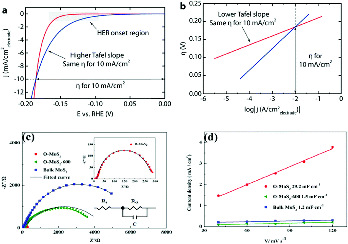 | ||
| Fig. 143 Basics of water electrolysis kinetic markers’ determination, for the example of the HER. (a) HER onset potential and overpotential at a current density of 10 mA cm−2 and (b) corresponding Tafel slopes. The blue electrocatalyst would be better for operation at low current density, while the red one would be better at high current density (i.e., in an industrial water electrolyser). Reproduced from with permission from ref. 1746 with permission from the American Chemical Society. (c) Example of electrochemical impedance spectroscopy measurements (EIS) enabling double layer capacitance measurements and (d) similar determination of the double layer capacitance from cyclic voltammetry measurements. Reproduced from ref. 1755, with permission from Elsevier. | ||
3-Electrode cell measurement are ideal for ECSA characterisations because they enable to really isolate the behaviour of the working electrode. These measurements are possible for PGM-based catalysts, either by hydrogen underpotential deposition (Pt, Pd), CO-stripping (Pt, Ru), metal oxide reduction (all PGM and alloys, as exemplified in1747–1750). When the electrocatalyst is non-PGM, only the latter technique makes sense,1286 but is not necessarily very practical. For Ni-based catalysts, integrating the peaks relative to the NiII/Ni transition enables to assess the developed area of metallic nickel, while that of the NiIII/NiII transition enables to evaluate the active area of oxidised nickel,96,1751,1752 similar measurements being also possible with Co-oxide based catalysts.1753 For materials like MoS2, transition metal oxides, (including noble ones1754) etc., one can simply measure the double layer capacitance of the catalyst material in a potential region where the electrode does not lead to quantitative change of oxidation state (by cyclic voltammetry833 or by EIS,1755Fig. 143c and d), or in a region where a characteristic redox is witnessed by cyclic voltammetry,244,1755 these values possibly being calibrated via sorption isotherm measurements.1756
A very important aspect of electrochemical characterisations of water electrolysis catalysts is to find experimental markers to quantify the initial catalytic activity for the desired reaction (HER or OER), or (better) at the same time the activity and short-term stability of this activity. Indeed, as stated in opening of this section, the operating conditions of water electrolysis are very harsh (highly reducing conditions at the cathode, and highly oxidising conditions at the anode, not speaking from the hindrances connected to the evolution of gas bubbles and the rather high temperature and operating current density of industrial cells). To that goal, authors regularly propose metrics, and some relevant ones are listed hereafter.
An example of figure-of-merit is the electrocatalyst ability to exhibit the lowest overvoltage when delivering a small (not to be limited by mass-transport) but non-negligible (not to be biased by capacitive currents) current (e.g., 10 mA cm−2 in absolute value) of HER or OER (Fig. 144a). Other authors propose to compare the mass or specific activities of the catalyst materials,244,1752,1757 usually evaluated at a relevant electrode potential value. Used in combination with the proper ECSA characterisation of the catalyst, these markers enable to assess the turnover frequency (TOF) or turnover number (TON) of the catalytic sites at stake.1757 A refinement is to evaluate the overpotential value measured at a relevant current density (e.g., +/− 10 mA cm−2) versus the same after 2 h of operation.833,1758 Another metric is the so-called “stability number” which was recently proposed to benchmark electrocatalyst stability from 3-electrode cell measurements; it has been set for Ir-containing catalysts and is defined as the ratio between the amounts of evolved oxygen and dissolved iridium, thereby linking the activity to the stability of the OER materials.1759 Thanks to this methodology, Cherevko et al. proposed that for many OER catalysts, the activity scales inversely to the durability (evaluated in the short-term), which would mean that active catalysts would not be durable in operation.1759 This vision is however not unanimous, others claiming that accelerated degradation tests performed in 3-electrode cell measurements at the lab scale do not necessarily match real water electrolysis data, and that real electrolyser cell experiments only should be used to evaluate the catalysts’ durability.20 One illustration of this drawback of 3-electrode cell measurements was recently provided by the group of Gasteiger: chronopotentimetric measurements performed in the RDE setup, fail to provide information on the long-term stability of nanostructured OER catalysts, as a result of the bubbles build-up in the volume of the thin layer of catalyst immobilised at the RDE tip (Fig. 144), the mass-transport in RDE being incapable to effectively evacuates these trapped bubbles in long-term RDE operation.20,1760,1761 They however remark that (short-term) catalytic activity of HER and OER can be relevantly assessed in RDE configuration.20
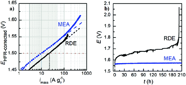 | ||
| Fig. 144 Evaluation of the OER (a) activity and (b) stability versus time at a given representative OER current in MEA (blue) and RDE (black) configuration for a state-of-the-art commercial IrO2 catalyst. Reproduced from ref. 20 with permission from Wiley. | ||
This short literature review shows that bridging the short time scale fundamental experiments to the long-time scale in real operation is therefore still very needed, and indeed, the research community actively addresses the issue nowadays. More insights into this topic will be provided in Section 12.
11.3 Physicochemical techniques coupled to electrochemistry to unveil how water electrolysers and their core materials operate
Several ex situ materials characterisation techniques (electron microscopies, X-ray diffraction, Raman and infra-red spectroscopies, chemical or elemental analyses, etc.) find their interest to determine the (initial or post-test) composition and microstructure of water electrolysis catalysts and evaluate whether these properties are positive or negative with respect their catalytic activity for the HER and OER and/or their durability in operation. When used ex situ, these techniques are common for scientists of the field of fuel cells/electrolysers and are by no means specific to water electrolysis. In that context, they will not be addressed here in more details. Other advanced ex situ techniques enable to probe the surface composition and/or electronic states of catalysts; atomic probe tomography,1762 X-ray emission spectroscopy (XES) and X-ray photoelectron spectroscopy (XPS)1763 are for example encountered in the recent OER literature to explore the fine composition and electronic properties of OER catalysts. Ex situ (and non-necessarily associated with electrochemistry) methods are also used to characterise non-catalytic material of the water electrolysis cell. A few examples are provided hereafter in a non-exhaustive manner. Porosimetry (i.e., mercury intrusion porosimetry1732) enables to assess the gas transport properties of electrodes and porous transport layers (PTL).1711 The wetting properties of the PTL are also of importance since these drive the nucleation and evacuation of the bubbles from the PTL surface in liquid water.1764 Basic corrosion and interfacial contact resistance measurements enable to test potential bipolar (or separator) plate materials.241Now, the real endeavour in characterising water electrolysis materials processes is to perform such characterisations under current load, i.e., in situ or operando. Such methodologies have really been democratised for two decades, from the fast and remarkable development of numerous physicochemical characterisation tools, that are available at synchrotron beamline, or even at the laboratory scale. The most striking of them are listed hereafter, in a non-exhaustive manner, recent reviews providing more depth on this matter.1765,1766
One technique of choice when it comes to water electrolysis is to detect the gas bubbles, using tailored cells with windows and fast video-cameras, when then help to model the hindrance of the bubbles on the cell performances.1717,1767 This is particularly important for membraneless systems (e.g., alkaline water electrolysers) in which bubbles compromise the ionic conduction in the electrolyte, can favour products intermixing, hence decrease of the FE safety issues.240Operando dynamic specific resistance measurement was also proposed to evaluate how gas bubbles do detach during the OER on vanadate-modified surfaces.1768 Such observations are often at the basis of modelling of the electrolyser operation,1769
On-line gas chromatography238 or mass-spectrometry1770 are useful when it comes to analyse the purity of the H2 or O2 gases that exit the cell (two-electrode operation, in real water electrolyser cell); they can also be used in more model conditions (3-electrode cell), to evaluate the capabilities of one material towards the desired reaction and to probe possible (gas-evolving) parasitic reactions (e.g. Cl2 evolution in sea-water electrolysis, CO2 formation from carbon oxidation). Differential electrochemical mass spectrometry (DEMS) enables such measurements and can quantify gaseous or volatile species,110,1771 particularly in transient (non-stationary) conditions, e.g., during accelerated degradation tests. DEMS or on-line EMS can be used with isotopic materials and water, to further shed light on the activity or degradation mechanisms, for example to illustrate whether lattice oxygen from metal oxides is evolved or not during OER.1772
X-ray are unique probes when it comes to in situ or operando characterisation of catalytic materials. X-ray Absorption Spectroscopy (XAS) enables the analysis of the chemical state, oxidation state of water electrolysis catalysts in operation (under potential control), and can enable to reconstruct the surface structure of operating active sites, an endeavour into the elucidation of the complex OER or HER mechanisms.110,1752,1753,1771–1774 XAS has for example been coupled with operando X-ray scattering and density functional theory (DFT) calculations, to unveil the catalytically active phase, reaction center and the OER mechanism of NiFe and CoFe (MFe) layered double hydroxides (LDHs) catalysts for the alkaline OER.1775 High-energy X-ray diffraction can also be performed operando, leading to the fine structure of the nanostructured catalysts upon water electrolysis; performed on IrNi@IrOx core–shell nanoparticles and combined with XAS and DFT calculations, it enabled to assert that lattice vacancies are generated following nickel leaching during the catalyst's activation, thereby producing shortened Ir–O metal ligand bonds and larger number of d-band holes in the iridium oxide shell, which overall increases the materials OER activity.1776Operando wide angle X-ray scattering (WAXS) complements the picture, enabling to access very fine geometric parameters of the catalyst materials’ lattice upon operation1775 (Fig. 145).
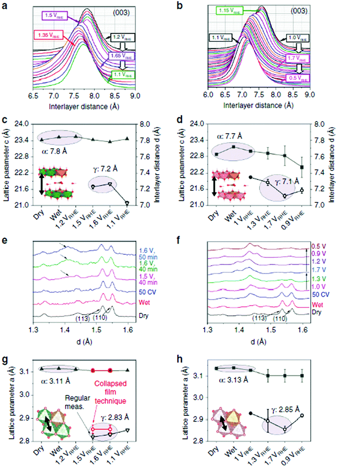 | ||
| Fig. 145 Evolution of the interlayer spacing and intralayer metal–metal distances of NiFe and CoFe LDHs from WAXS measurement. (a and b) Normalized and background-subtracted (003) peak obtained during in situ WAXS in 0.1 M KOH and potential steps for NiFe LDH (a) and CoFe LDH (b). (c and d) Interlayer distances for NiFe LDH (c) and CoFe LDH (d) obtained by Rietveld refinement. (e and f) In situ WAXS patterns for d-values close to the (110) peak of NiFe LDH (e) and CoFe LDH (f). For NiFe LDH, the WAXS patterns at the reported potentials were obtained by the collapsed film technique. In e, the dashed arrows highlight the feature associated to the γ-phase. (g and h) Lattice parameter a, corresponding to the intralayer metal–metal distance in NiFe LDH (g) and CoFe LDH (h) obtained by Rietveld refinement. Full and open symbols are used for different phases. Error bars represent SD provided by Topas for the refined parameters. Reproduced with permission from ref. 1775 Copyright Springer-Nature 2020. | ||
Near-ambient pressure X-ray photoelectron spectroscopy (nap-XPS) cannot be considered a real operando technique for water electrolysis; however, it enables to evaluate the state of surface of catalysts materials when in contact with ca. 20 mbar of gaseous species (e.g., H2, O2, H2O), which can provide insights into the behaviour of the materials in real operation.1765,1777–1781 Like for other operando spectroscopies, these measurements are only possible provided the in situ cell and operating conditions are optimised both for the electrochemical and spectrometric insights, a difficult task at electrified solid|liquid interfaces on which gas bubbles are permanently released.1780,1781
Raman spectroscopy is a powerful tool to characterise oxides and was historically used prior/after electrochemistry to unveil how catalysts changed upon OER operation.1782 Until recently, operando Raman was not conducted to characterise water electrolysis reactions, because of obvious experimental issues induced by the unavoidable bubbles’ evolution. The picture changed starting in 2011 when Yeo and Bell performed in situ Raman spectroscopy to evaluate cobalt oxide OER catalysts.771 Then in 2015, Kornienko et al. combined operando Raman spectroscopy and XAS to characterise CoS2 catalysts under HER regime;1783 their results enabled to build a molecular model in which the cobalt atom is in an octahedral CoS2-like state and is surrounded by a first shell of sulphur atoms, the latter being preferentially exposed to electrolyte relative to bulk CoS2. They proposed that such CoS2-like clusters are generated in cathodic polarisation, thereby exposing a high density of catalytically active sulphur sites for enhanced HER. Other studies using Raman spectroscopy soon followed,1768,1784–1790 demonstrating its clear interest to unveil catalysts’ structural changes upon operation, elucidate their possible active sites and the intermediates formed during (water) electrolysis.
Electrochemical quartz crystal micro/-nanobalance is also a reported technique to survey water electrolysis catalysts.1785 Firstly, demonstrated for very model Pd surfaces,1791 it has since them been used for more practical nanostructured catalysts.1792–1794
Inductively coupled plasma mass spectrometry (ICP-MS), a classical technique for trace analyses, was recently coupled on-line to electrochemistry by the group of Mayrhofer. Initially demonstrated for corrosion applications and then fuel cell catalysis, the technique has been employed with great success to probe the short-time stability of water electrolysis catalysts, upon fast-potential variation experiments.1795–1799 However, this tool is employed, so far, with liquid electrolytes and in operating conditions that may non-negligibly differ from the real application, and therefore it has yet to be demonstrated that the conclusions deriving from such measurements fully apply to the same catalyst materials when operated in real water electrolysers.20
Because the management of bubbles and liquid water is critical in low-temperature water electrolysers, and because this largely depends on the porosity and porous structure of the catalyst layers and porous transport layers, X-ray tomographic microscopy imaging is popular to study PEMWE electrodes and unveil their porous structure/morphology1800,1801(Fig. 146). By measuring the influence of the PTL structure on the mass transport overpotential versus the current density, operating pressure and temperature, the authors1192 demonstrated that the interface properties between the catalyst layer and the PTL had a major influence on the cell performance.
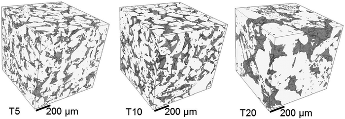 | ||
| Fig. 146 Example of tomographic elucidation of a PTL porous structure. Reproduced with permission from ref. 1801. Copyright Elsevier 2017. | ||
Water management in a water electrolyser is a critical issue, as is in PEMFECs or in AEMFCs. It can be surveyed by Small Angle Neutron Scattering (SANS) in operating cells, as initially demonstrated by Morin et al. in operating PEMFC1802 and lately applied to evaluate water electrolysis membranes.1803 Neutron imaging methodologies now start to be used for two-phase flow investigations in the porous structure of PEMWE electrodes and PTL,1804 which enables unveiling the mass-transport mechanisms.1805
This selected literature review demonstrates that the research community is very active and inventive to finds manner to elucidate complex problems. The techniques listed here have all great interest to improve water electrolyser materials and cells. However, long-term operation and durability in these conditions can only be relevantly assessed by tests performed in real electrolysers, which is the topic of Section 5.
12 Enhanced water splitting with externally applied fields
In general, in electrochemistry, the overpotential (η) of a galvanic and electrolytic cell is made of three important components: the activation overpotential (ηactivation), the Ohmic overpotential (ηOhmic) and the concentration overpotential (ηconcentration), each term having an impact on the cell efficiency. Low-temperature water electrolysers have many assets, although they suffer from molecular hydrogen and oxygen bubble accumulation at the electrode surfaces and in the electrolyte, leading to a high Ohmic voltage drop (IR) and a large reaction overpotential in turns yielding high operational energy consumption and costs.1806,1807H2 and O2 gas bubble evolutions during electrochemical water splitting lead to electrochemical losses, owing to the fact that the electrochemical reaction rates for both reactions are purely controlled by the interfacial phenomenon in the three-phase zone (TPZ) where H2 and O2 gas bubbles, electrolyte and electrode surface are in contact with each other.1808 In first approximation, the practical cell voltage (Vcell) for electrochemical water splitting technologies obeys eqn (19).1806–1808
| Vcell = |Ec − Ea| + I × ∑R = Erev + |ηa| + |ηc| + I × (Rc + Rm + Rb + Re) | (19) |
Eqn (19) shows that Vcell depends greatly upon the overpotential and Ohmic voltage drop and therefore, reducing the anodic and cathodic overpotentials (ηa, ηc) and the total Ohmic resistance (∑R) is paramount to reducing energy consumption. During water electrolysis, Rc and Rm are usually constant and can be reduced by better wiring and membrane/separator optimisation. However, it is not the situation for Rb as many evolved gas bubbles generated on the electrode surfaces act as an insulating layer (similar to “passivation”), which significantly reduces the effective electrode surface area (Aeff). In this case, the bubble coverage (θ) on the electrode surface yields increased bubble resistance, Rb. This fraction of the electrode surface covered with “sticking” i.e., adhering gas bubbles is well-known to affect substantially: (i) the mass (m) and heat (h) transfer, (ii) the limiting current density (jlim), (iii) the overpotential and (iv) the Ohmic resistance (∑R). In other words, when the evolved gas bubbles cover the electrode surface, they cause electrolyte access blockage and lead to reactant starvation resulting to an exponential increase of the cell voltage with the current density (j). Since the Ohmic resistance and the overall cell overpotential depend on bubble surface coverage, θ, effective gas-bubbles removal at the electrode surface should in theory reduce the cell voltage.1808 Additionally, the dispersion of the bubbles in the electrolyte decreases its conductivity and in turns increases Re and thus, the current distribution on the electrode surface increases yielding high cell voltages.1810–1812
In general, hydrogen and oxygen gas bubbles evolving on the electrolyser electrode surfaces and in an electrolyte affect: (i) ηactivation as the adhering bubbles decrease Aeff, (ii) ηOhmic due to a blockage of ionic pathways available for electronic transport, and (iii) ηconcentration due to the dissolved gas products and the decrease in supersaturation levels within the electrolyte. There are several methods for reducing the total overpotential and total Ohmic resistance in water electrolysis, for example, by either increasing the electrolyte movement i.e., mass-transfer, by using gravity,1810,1811 by centrifugal acceleration field,1812 by mechanical stirring,1813,1814 by using a magnetic field,1809,1812–1820 or by employing ultrasound,1821–1836 at the gas-evolving electrodes and electrolyte.
12.1 Mechanical stirring
Many studies have shown that stirring the electrolyte away from/at the electrode surface affects gas-bubble evolution and hence bubble coverage.1813,1814 Eigeldinger and Vogt1813 demonstrated that electrolyte flow past the electrode surface strongly affects the fractional bubble coverage and increasing the flow rate lowers the bubble coverage, increases efficient gas bubble removal at the electrode surface, and in turns reduces the Ohmic resistance, electrode overpotential and the limiting current density. However, as stated in Section 9, mechanical stirring only affects the “surface” of the electrode and not its inner porosity, in which bubbles might remain trapped. This is even the case in small-scaled porous rotating disk electrode layers, as put forth by the group of Gasteiger.1760,176112.2 Magnetic field
Magneto-electrochemistry is a niche area of electrochemistry that has been around for over 40 years, in which magnetic fields are applied to electrochemical systems. It was found that magnetic fields affect mass-transfer, limiting current density and charge-transfer due to Lorentz and Kelvin forces, magneto-hydrodynamics (MHD), chiral-induced spin selectivity, and hyperthermia (local heating of the electrode materials).1815 A recent contribution of some of the authors reviews magnetic effects in electrochemistry.1815In the literature, there are several studies that focus on applying magnetic fields to water electrolysis. Overall, magnetic forces (Lorentz and Kelvin) improve bubbles’ removal at the electrode surface, enhance mass-transfer, reduce cell voltage and electrolyte/electrode Ohmic resistance. Employing ferromagnetic catalysts can yield improved efficiencies than those using paramagnetic and diamagnetic catalytic materials.1809,1816
For example, Iida et al.1817 reported improved water electrolysis efficiencies by reducing the electrode overpotential in a magnetic field under alkaline (4.46 and 0.36 M KOH) and acidic (0.05 M H2SO4) conditions. The OER overpotential was further reduced than the HER overpotential under the presence of a magnetic field, due to the different gas bubble sizes from both processes. They associated the findings to MHD convection, that affects bubbles’ detachment at the electrode surface, leading to a significant reduction of the void fraction and surface coverage by the gas bubbles: MHD convection plays an important role for bubbles’ nucleation, growth and detachment.1818
Using a specially-designed electrode (transparent glass) for AWE, Matsushima et al.1819 showed that the magnetic field (1.0 T) affects gas bubble removal remarkably due to MHD convection. Lin et al.1820 applied simultaneously pulse potentials (up to 4 V) and magnetic fields (up to 4.5 T) to Ni electrodes immersed in KOH. By applying this strategy, they managed to reduce power consumption by 88% with a 38% increase in current compared to conventional DC electrolysis. Kaya et al.1837 showed that by using cost-effective graphite (anode) and high carbon steel (cathode) electrodes immersed in low KOH concentrations (5–15 wt%) and in the presence of a magnetic field, higher hydrogen production rates (up to 17%) when compared to conventional conditions were achieved. They attributed the findings to efficient hydrogen and oxygen gas bubbles removal at the electrode surfaces caused by MHD convection. The same group1838 demonstrated that by applying a magnetic field (0.5 T) on a single PEMWE cell could improve performances up to 56% (@ 2.5 V), particularly at lower flow rates, where Lorenz and buoyancy forces are predominant towards gas bubbles’ removal.
The use of magnetic field to improve water electrolysis is currently seen as a promising method to reduce the so-called “bubble overpotential”, to minimise power consumption and thus to increase electrolyser efficiencies. As an example, in 2021, the European Commission granted a 4 year project (June 2021–May 2025) under the EU Horizon 2020 programme entitled “Spin-polarised Catalysts for Energy-Efficient AEM Water Electrolysis – SpinCat”.1839 SpinCat develops a series of novel magnetic earth-abundant catalysts that can enhance OER catalytic activity by a factor of three via the use of magnetic fields (spin polarisation) as compared to state-of-the-art OER catalysts.
In an alternative approach, some of the authors of the contribution used alternative magnetic field and magnetic@catalytic (FeC@Ni core–shell) nanoparticles to heat the latter to their Currie temperature and promote enhanced HER and OER.29 It is possible that other magnetic effects as those listed above and recalled in ref. 1815 are also at stake in their experiments.
12.3 Ultrasound in water splitting
Another method is to apply power ultrasound,1840 sonochemistry1841 (ultrasound in chemistry) and sonoelectrochemistry1841,1842 (ultrasound in electrochemistry) in the solution and at the gas-evolving electrode. The use and application of ultrasound in chemical, physical and biological sciences can be divided into two distinct groups: (a) low frequency ultrasound or power ultrasound (20 kHz–2 MHz) and (b) high frequency ultrasound or diagnostic ultrasound (2–10 MHz). Power ultrasound (PUS), a process intensification technology, is regarded as the propagation and the effect of an ultrasonic wave when transmitted through a liquid, leading to (i) the creation of cavities (or voids) and cavitation bubbles (acoustic cavitation bubbles) as well as (ii) acoustic streaming.Acoustic cavitation of an ultrasonicated liquid can be defined as the activation of pre-existing nuclei to form stable or transient bubbles in the liquid. These cavitation bubbles usually contain gas molecules such as N2, O2 and other gases as well as vapour from the liquid. When these bubbles grow in size, they become unstable and then violently collapse creating localised transient high temperatures and pressures at STP. The collapsing of these acoustic bubbles on a solid surface also leads to the formation of microjets being directed towards the surface of the solid material at speeds of up to 200 m s−1. It is well-accepted in the field that the cavitation bubble collapse leads to near adiabatic heating of the vapour that is inside the bubble, creating the so-called “hotspot” in the liquid, where: (1) high temperatures (ca. 5000 K) and high pressures (ca. 2000 atms) are generated with a collision density of 1.5 kg cm−2 and pressure gradients of 2 TPa cm−1, with lifetimes shorter than 0.1 μs and cooling rates above 109–10 K s−1 during the collapsing of cavitation bubbles. At the high temperature and pressure generated by bubble collapse, the liquid vapour and gas molecules generate various highly reactive radicals and other species1845 (Fig. 147).1846
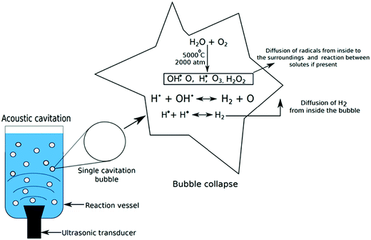 | ||
| Fig. 147 Production of sonolysis species by acoustic cavitation.1846 | ||
In the case of ultrasonicated water, water vapour is ‘pyrolysed’ into these ‘microreactors’ and dissociates to lead to the formation of extremely reactive species such as hydroxyl radicals (˙OH), hydrogen radicals (H˙), and hydroperoxyl radicals (˙OOH) as well as hydrogen peroxide (H2O2) – a process known as water sonolysis.
| H˙ + H˙ → H2 (x) |
| H˙ + ˙OOH → O2 + H2 (x) |
| H˙ + H2O → ˙OH + H2 (x) |
| H˙ + H2O2 → H2 + HO2˙ (x) |
To this day, there are a few reports focusing solely on the application of ultrasound for the production of hydrogen. For example, Sasikala et al.1846 showed that hydrogen produced by water sonolysis can be improved by adding suspended metal oxide microparticles (γ-Al2O3, TiO2 and SiO2) during ultrasonication, due to the increased number of cavitation bubbles caused by the presence of these particles. They also demonstrated that hydrogen production rates significantly increased by adding methanol to water during ultrasonication, as it was found that the alcohol was efficiently scavenging ˙OH radicals and thus thwarting ˙OH and H˙ recombination.
However, since 2015, it has been an upsurge of interest in the area, for example, Merouani and Hamdaoui1847 by using modelling tools, reported in great detail the mechanisms of the sonochemical production of hydrogen. In 2019, Islam et al.1821 reviewed the area followed by Dincer et al.1822,1823 who investigated the challenges and opportunities of the use of ultrasound in hydrogen production.
Moriguchi1841 and Pollet et al.1827 showed that ultrasound decreases the electrode overpotential for the OER and HER on Ag, Pt and SS (stainless steel) electrodes immersed in aqueous solutions. Pollet et al.1827 also showed that the onset potentials for hydrogen and oxygen were both reduced with increasing ultrasonic power; no appreciable change in the Tafel slopes were observed, although the exchange current density (jo) values were different in the absence and presence of ultrasound. They postulated that this decrease in overpotentials could be due to either changes in electrode surface, changes in electrode surface temperature, degassing at the electrode surface or a combination of all.
Budischak et al.1828 also studied the effects of ultrasound on HER in 2.0 M KOH using Pt as a working electrode and found that ultrasound can greatly improve water electrolysis efficiency, especially at intermediate current densities. Li et al.1829 demonstrated that the HER was affected by ultrasound in a pseudo-water electrolyser comprising of two dimensionally stable anodes (DSA, RuO2 and IrO2 plated Ti electrodes) used as working and counter electrodes immersed in weak alkaline solutions (0.1 M, 0.5 M and 1.0 M NaOH). PUS aided in removing the thin layer of bubbles at the electrode surface, especially at lower concentrations, thus yielding energy saving for hydrogen production of up to 25%. In their conditions, no evident effects of ultrasound on the OER were observed. Li et al.1830 investigated the effects of ultrasound (25.3 kHz and 33.3 kHz) on a pure graphite electrode immersed in 0.40 M NaOH electrolytes; the cell voltage was much lower under ultrasonic conditions at the two frequencies employed than under silent conditions (cell voltage reductions at a current density of 200 mA cm−2 for 0.1 M, 0.5 M and 1.0 M NaOH was +320 mV, +100 mV and +75 mV respectively.
Pollet and co-researchers1831–1834 found that ultrasound could practically remove H2 and O2 gas bubbles efficiently from the electrode surfaces and electrolyte in turns improving electrochemical hydrogen and oxygen production rates. They investigated the effects of ultrasound (20 kHz) on hydrogen production from acidic and base electrolytes on several electrode materials used both as anodes and cathodes (316 stainless steel, carbon graphite, POCO carbon, Morganite carbon, nickel, and titanium);1831–1834 PUS increased the hydrogen and oxygen production rates due to the efficient electrode cleaning, electrode surface/solution degassing and enhanced mass-transfer of electroactive species to the electrode surface. Zadeh1833,1834 used ultrasound (20 and 40 kHz) to generate hydrogen from carbon and nickel alloy electrodes immersed in NaOH and KOH electrolytes (up to 15 M): the sonoelectrochemical hydrogen production is enhanced by 14% and 25% for NaOH and KOH respectively, the electrolyte conductivity playing an important role in the hydrogen yield.
Lin and Hourng1835 demonstrated by EIS that PUS (133 kHz @ transmitted powers of 225, 450, 675, and 900 W) enhanced the activity and concentration impedances and greatly improved the removal of hydrogen bubbles at Ni electrode surfaces immersed in a series of concentrations of 10, 20, 30 and 40 wt% KOH electrolytes: (i) at 30 wt% KOH and at low potentials, PUS improved the activation polarisation, and (ii) concentration polarisations were improved under ultrasonic conditions due to efficient degasification at the electrode surface. Under optimum conditions (+4 V, 40 wt% KOH, 2 mm electrode gap, 225 W), the difference in current density was found to be 240 mA cm−2 yielding a power saving of 3.25 kW and a gain in power efficiency of up to 15%.
In 2019, Islam et al.1841 reviewed the area showed that PUS can be a used as a powerful tool to overcome the limitations of electrochemical water splitting technologies for hydrogen production via: (i) electrode surface cleaning and activation, (ii) increased mass-transfer in the bulk electrolyte and near the electrode surface, and (iii) efficient degassing at the electrode surface and electrolyte. They also showed that ultrasound can improve the electrolytic efficiency (up to 15–20%) caused by increased ion concentration and bubble removal at the electrode surface (Fig. 148).
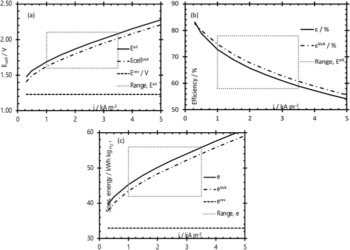 | ||
| Fig. 148 Effect of ultrasound on (a) cell voltage (Ecell), (b) efficiency (ε) and (c) specific energy (e) for hydrogen production (*UsA = ultrasound-assisted).1841 | ||
Very recently, it was observed by Pollet et al.1836 that ultrasound (26 kHz, up to ∼75 W cm−2, up to 100% acoustic amplitude, ultrasonic horn) significantly affects the HER currents with an ∼250% increase in current density achieved at maximum ultrasonic power on a Pt polycrystalline electrode immersed in a weak acidic electrolyte (0.5 M H2SO4; Fig. 149). At j = −10 mA cm−2, a ΔEHER shift of ∼+20 mV was observed, at 26 kHz and at 100% acoustic amplitude. At the same ultrasonic frequency and acoustic power, a nearly 100% increase in the exchange current density and a 30% decrease in the Tafel slope was observed in the low overpotential region, although in the high overpotential region, the Tafel slopes were not significantly affected when compared to silent conditions. Overall, ultrasound did not dramatically change the HER mechanism but instead, increased currents at the Pt surface area through effective hydrogen bubble removal).1836
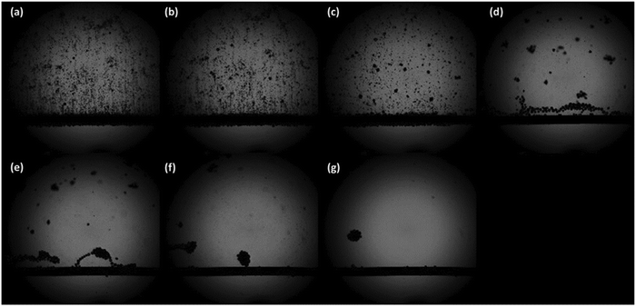 | ||
Fig. 149 Hydrogen evolution on a Pt wire in the absence (top left corner) and presence of ultrasound (26 kHz, 100% ultrasonic amplitude). The applied potential was set at −1.30 V vs. RHE – (a) 0 μs, (b) 100 μs, (c) 200 μs, (d) 300 μs, (e) 400 μs, (f) 500 μs, (g) 600 μs. The time between each image is 10−4 s (100 μs) filmed at 10![[thin space (1/6-em)]](https://www.rsc.org/images/entities/char_2009.gif) 000 frames per second. Reproduced with permission from ref. 1836. Copyright Elsevier 2020. 000 frames per second. Reproduced with permission from ref. 1836. Copyright Elsevier 2020. | ||
Overall, the effects of ultrasound on the HER and OER processes are due possibly due to the following combination of effects: (i) depolarisation mainly due to highly efficient electrolyte stirring, in turns reducing and even eliminating the contribution of concentration gradients to the overpotential, (ii) effective electrode surface activation caused by acoustic cavitation, and (iii) gas bubble removal from the bulk electrolyte and the electrode surface due to efficient degasification induced by intense agitation, acoustic cavitation and acoustic streaming. However, literature indicates that no studies have been undertaken to shed some light on whether power ultrasound affects the HER and OER mechanisms. Table 15 shows a summary of the experimental conditions employed for the sonoelectrochemical production of hydrogen.
| Ultrasonic frequency (kHz) | Ultrasonic power or intensity | Reactions | Electrode material | Electrolyte and concentration | Cell voltage (V) | Current density | Ref. |
|---|---|---|---|---|---|---|---|
| 30 | 1–2 W cm−2 | HER | Carbon rod | 6.0 M NaCl, 6.0 M HCl, 5.0 M NaCl + 1.1 M HCl | 8, 10, 12, 20 | 2.7, 6.5, 7.6 A dm−2 | 1824 |
| ClER | |||||||
| 38 | — | HER | Platinised platinum | 1.0 M H2SO4, 2.5 M NaCl/0.1 M HCl | — | 50 mA cm−2 | 1825 |
| OER | |||||||
| ClER | |||||||
| 20 | 26 W cm−2 | HER | Titanium alloy sonotrode | 0.7 M Na2SO4 (maintained pH at 7 by using 0.1 M NaOH) | — | — | 1826 |
| OER | |||||||
| 20 | 43 W cm−2 | HER | Ag, stainless steel, carbon, platinum | Na2S2O3/NaHSO3 | — | — | 1827 |
| 500 | OER | ||||||
| 42 | 300 W | HER | Platinum | 2.0 M KOH | — | — | 1828 |
| 60 | 50 W cm−2 | OER | DSA–RuO2 and IrO2 plated on titanium | 0.1, 0.5 M, 1.0 M NaOH | — | 20–400 mA cm−2 | 1829 |
| 25.3 | — | OER | Pure graphite | 0.40 M NaOH | — | 20–200 mA cm−2 | 1830 |
| 33.3 | |||||||
| 20 | 139.72, 1186.6, 2349.8 W | HER | Carbon graphite, POCO carbon, platinum | NaOH (0.1, 0.2, 0.3, 0.4, 0.5, 1.0 M) | — | <200 mA cm−2 | 1831 |
| 33 | OER | NaCl (0.1, 0.2, 0.3, 0.4, 0.5, 1.0 M) | |||||
| ClER | H2SO4 (0.1, 0.2, 0.3, 0.4, 0.5, 1.0 M) | ||||||
| 20 | 20.7 W cm−2 | HER | Carbon (Morganite) | NaOH (0.1, 0.2, 0.4, 0.5, 1.0 M) | <3 | <200 mA cm−2 | 1832 |
| 40 | OER | NaCl (0.1, 0.2, 0.4, 0.5, 1.0 M) | |||||
| ClER | H2SO4 (0.1, 0.2, 0.4, 0.5, 1.0 M) | ||||||
| 20 | — | HER | Carbon, nickel alloy (Rolls-Royce) | 0.1 M NaOH | <3 | <200 mA cm−2 | 1833 |
| 40 | OER | 0.1 M, 1.0 M, 10 M, 15 M KOH | |||||
| 20 | — | HER | Nickel | 0.1 M NaOH | <3 | <200 mA cm−2 | 1834 |
| OER | 0.1 M KOH | ||||||
| 133 | 225, 450, 675, 900 W | HER | Pure nickel | 10, 20, 30, 40 wt% KOH | <4 | <2 A cm−2 | 1835 |
| OER | |||||||
| 26 | 75 W cm−2 | HER | Pt | 0.5 M H2SO4 | — | — | 1836 |
As a conclusion to this section, it must be mentioned that, although many different physic-assisted water electrolysis concepts have been successfully demonstrated, the net gain in efficiency has not be precisely quantified, i.e., the cost of generation of the physical signal has not been optimised (and in some case evaluated) versus the gain in electrochemical output. In essence, doing so is not easy, especially at the laboratory scale, and only well-dimensioned setups (production plants) will enable really assessing where the game is worth to be played. So, there is a wealth of technological and industrial studies that need to be achieved prior these physics-assisted water electrolysis processes become an industrial reality.
13 Water splitting from seawater, wastewater and other non-pure sources
The electrochemical splitting of pure water requires substantial electrical input energy, since the resistance of pure water is 18 MΩ cm. In contrast, the resistance of tap water and seawater are up to six orders of magnitude lower (RSeawater = 20 Ω cm) which, viewed from the perspective of conductivity, in principle allows energy efficient splitting of water. Sea water covers nearly 70% of the earth's surface and presents the most abundant aqueous feedstock on earth (∼97% of the total water1848). In areas where fresh water is scarce, the direct use of seawater is advantageous to avoid the costs of water treatment. However, seawater is highly corrosive and contains Cl−![[thin space (1/6-em)]](https://www.rsc.org/images/entities/char_2009.gif) 1849 (3.5% average global salinity) and microorganisms1850 that can impact metal corrosion. Especially the chloride anions (∼0.5 M in seawater) poses serious challenges for the OER electrode that is set to oxidative hence positive potentials. Parasitic electrochemical reactions can occur on the anode and may lead to side products like chlorine or binary Cl–O compounds. Perhaps these reasons are basically responsible that the number of reports dedicated to electrocatalysis of seawater remains till to date within a manageable range.503,1851–1861,1864,1868 Oxygen evolution and chlorine evolution will in general always compete with each other, and since chlorine is a valuable intermediate in industry, it depends on perspective to decide whether OER or CER is the undesirable parasitic reaction.1862,1863 It is therefore understandable that electrocatalysts that are able to selectively support or suppress one or the other reaction are of great interest.1862
1849 (3.5% average global salinity) and microorganisms1850 that can impact metal corrosion. Especially the chloride anions (∼0.5 M in seawater) poses serious challenges for the OER electrode that is set to oxidative hence positive potentials. Parasitic electrochemical reactions can occur on the anode and may lead to side products like chlorine or binary Cl–O compounds. Perhaps these reasons are basically responsible that the number of reports dedicated to electrocatalysis of seawater remains till to date within a manageable range.503,1851–1861,1864,1868 Oxygen evolution and chlorine evolution will in general always compete with each other, and since chlorine is a valuable intermediate in industry, it depends on perspective to decide whether OER or CER is the undesirable parasitic reaction.1862,1863 It is therefore understandable that electrocatalysts that are able to selectively support or suppress one or the other reaction are of great interest.1862
The authors dare to say that, whenever hydrogen is intended to be produced electrochemically, the OER will be (compared to CER) the preferred other water-splitting half-cell reaction because transportation of chlorine is difficult and the projected hydrogen demand is enormous and hard to bring in line with the local chlorine demand.
The water oxidation reaction obeys the Nernst equation and consequently shows strong pH dependence. Unlike OER, the equilibrium potential of the chorine evolution reaction (CER):
| 2Cl− → Cl2 + 2e− | (20) |
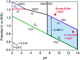 | ||
| Fig. 150 Pourbaix diagram for electrolysis of 0.5 M NaCl. The electrode potential for OER is included as well, assuming oxygen partial pressure of 0.021 MPa. The red square points show the operating potentials (vs. SHE) after 1 h constant current density of 10 mA cm−2 with NiFe LDH catalyst in 0.1 M KOH + 0.5 M NaCl (pH 13) and 0.3 M borate buffer + 0.5 M NaCl (pH 9.2) electrolyte. Reproduced with permission from ref. 1864 Copyright Wiley 2016. | ||
In contrast to the four-electron oxidation reaction OER, CER is a two-electron reaction with only a single intermediate. Due to the faster kinetics, the parasitic CER can become the dominant anodic reaction in acidic electrolytes on several metal oxide-based electrocatalysts.1862,1866,1867 A more substantial broader gap between onset of OER and CER obtained at pH 0 can be expected at somewhat higher pH (up to pH 3). At even higher pH values, a second parasitic, electron-consuming reaction must be considered, namely the hypochlorite formation reaction (HFR):
Cl− + 2OH− → ClO− + H2O + 2e− E0 = +0.89 VNHE,pH![[thin space (1/6-em)]](https://www.rsc.org/images/entities/char_2009.gif) 14 14 | (21) |
All of these considerations inevitably show that water splitting of chloride ion containing media is more advantageous in alkaline media than in the neutral or acidic regime. To the best of the authors knowledge, Bennett et al.503 was the first to report on the direct electrolysis of seawater. Current densities of 155 mA cm−2 in conventional seawater electrolysers equipped with standard electrodes, i.e., TiO2/RuO2-based DSA, PbO2, and graphite electrodes, exhibited a faradaic efficiency for chlorine evolution up to 92% upon exploitation of neutral, unbuffered seawater. OER and CER taking place on the anode led to a substantial drop of the pH of the electrolyte in the immediate vicinity of the electrode based on the equations,
| 2H2O → O2 + 4H+ + 4e− | (22) |
| Cl2 + H2O → HClO + Cl− + H+ | (23) |
A Japanese group took advantage of this material and modified MnO2 (deposited on IrO2-coated titanium substrate) for water electrolysis of seawater, showing high selectivity towards oxygen evolution by doping with molybdenum or tungsten,1851–1853 or by simultaneous addition of both transition metals.1854 This group reported later on more temperature-stable (up to 90 °C) triple oxide-based anodes.1855
Thin films of Nocera's Co–Pi system were also found to be suitable electrocatalysts for selective water oxidation in Pi electrolyte in the presence of 0.5 M NaCl at neutral pH.1868 The buffer solution used by the authors suppresses an acidification of the electrolyte. However, the current density (around 1 mA cm−2) was too low to be of practical importance and most likely chlorine formation was simply not obtained due to the weak oxidative potential applied to the anode (1.30 V vs. NHE).
Taking into consideration both thermodynamics and kinetics, Dionigi et al. defined design criteria for reasonable seawater splitting and chose 480 mV as the upper limit for the OER overpotential (at j = 10 mA cm−2) and 7.5 as the lower pH value of the electrolyte based on the fact that, below pH 7.5, the gap between E0 (HFR) and E0 (OER) becomes smaller than 480 mV (Fig. 150).1864 The authors synthesised NiFe-layered double hydroxide (NiFe LDH) by a solvothermal method.1864 Glassy carbon (GC) with 0.1 mg cm−2 NiFe-LDH loading used as an OER electrode in borate buffer (pH 9.2) and 0.1 M KOH (pH 13), with or without additional NaCl (0.5 M) exhibited 100% oxygen/hydrogen selectivity. Chloride ions did not adversely affect the OER activity of the NiFe LDH catalysts at current densities up to 10 mA cm−2 and, in case of pH 9.2, chloride ions even boost the OER activity (Fig. 151).
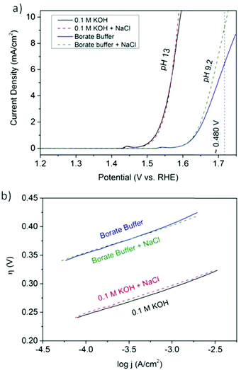 | ||
| Fig. 151 (a) Electrocatalytic OER activities of NiFe LDH nanoplates supported on carbon, measured using LSV in four different electrolytes after CV “break-in” (50 cycles). A potential of approximately 480 mV, corresponding to the design criteria limit, is marked by a dashed vertical line. (b) Corresponding Tafel plot for low current density j. Measurement conditions: room temperature, 1600 rpm, and scan rate of 1 mV s−1. Reproduced with permission from ref. 1864. Copyright Wiley 2016. | ||
Industrially required current densities (0.4 < j < 1 A cm−2) that can be realised in long-term experiments without substantial degradation of the catalytically active compounds are for most of the common electrode materials still very challenging. Kuang et al.1857 recently reported a multilayer (hierarchical) anode consisting of NiFe hydroxide coated on a nickel sulphide (NiSx) layer formed on porous Ni foam (NiFe/NiSx–Ni). They stated that, during anodic activation of NiFe/NiSx–Ni successively in 1 M KOH and in 1 M KOH/0.5 M NaCl, sulphate ions and carbonate ions are formed and intercalated in the NiFe-layered double hydroxide which increased the OER activity (Fig. 152).
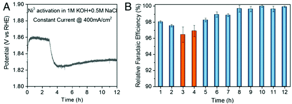 | ||
| Fig. 152 Cation-selective layer generation during anodic activation (A) chronopotentiometry plot whilst second activation step in salty electrolyte. (B) The associated OER relative faradaic efficiency plots for O2 production. Reproduced with permission from ref. 1857 Copyright PNAS 2019. | ||
Obviously polyanion-rich passivating layers are in situ-generated in the anode and lead to a repelling of chloride anions and thus suppress parasitic reactions with chlorine containing reactants.
Full water splitting upon exploitation of an anode designed in this way and a Ni–NiO–Cr2O3 hydrogen evolution reaction cathode was shown at a cell voltage of 1.7 V as delivering j = 400 mA cm−2 current density in 6 M KOH/1.5 M NaCl at 80 °C1857 (Fig. 153).
 | ||
| Fig. 153 Durability tests (1000 h) recorded at a constant current of 400 mA cm−2 of the seawater-splitting electrolyser under 1 M KOH + real seawater at room temperature and 6 M KOH electrolyte at 80 °C, respectively. (h) Reproduced with permission from ref. 1857. Copyright PNAS 2019. | ||
In a more recent work, commercial Ni foam was converted via a one-step surface modification route into a porous, S-doped Ni/Fe (oxy)hydroxide electrocatalyst capable for water oxidation performed in 1![[thin space (1/6-em)]](https://www.rsc.org/images/entities/char_2009.gif) :
:![[thin space (1/6-em)]](https://www.rsc.org/images/entities/char_2009.gif) 1 mixtures of 1 M NaOH and 1 M NaCl at pH 14 reaching a current density of 100 mA cm−2 at around 300 mV overpotential.1859
1 mixtures of 1 M NaOH and 1 M NaCl at pH 14 reaching a current density of 100 mA cm−2 at around 300 mV overpotential.1859
The approaches that scientists developed for splitting salty electrolytes are not solely restricted to metal-based substrates. Song et al.1858 recently developed carbon-coated sodium cobalt-iron pyrophosphate (Na2Co1−xFexP2O7/C; 0 ≤ x ≤ 1) nanoparticles loaded on carbon cloth (NCFPO/C@CC) as a promising OER electrocatalyst for alkaline seawater electrolysis. The catalyst exhibited competitive current density to overpotential relationship (η = 270 mV at j = 10 mA cm−2) in 0.1 M KOH/0.5 M NaCl solution mixtures as well as long term durability. Even at j = 50 mA cm−2, this material showed an OER FE of close to 100% (Fig. 154).
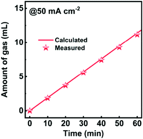 | ||
| Fig. 154 Theoretically calculated and experimentally measured O2 amounts for NCFPO/C@CC as a function of time in the NaCl + KOH electrolyte. Reproduced with permission from ref. 1858. Copyright ACS 2020. | ||
As already mentioned, it is particularly difficult to selectively form O2 gas in the acidic range at the anode in the presence of chloride ions. This is certainly the reason why studies reporting saltwater electrolysis at low pH levels can rarely be found. Ko et al.1860 chose a not very widely used method for the generation of OER electrodes. A series of catalysts have been produced by pyrolysing Ir organometallics in the presence of a Norit® activated carbon as conductive substrate. Tailored heteroatom doping is possible through specific choice of the Ir organometallic compound (Fig. 155). Due to low Ir doping (2–6 wt%), the overall costs can be kept within limits. A respectably low overpotential (η = 283 mV) was required for j = 10 mA cm−2 OER-based current density in 0.1 M HClO4 + 5 wt% NaCl.
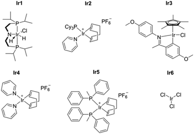 | ||
| Fig. 155 Survey of Ir-based organometallics subject to pyrolysis with activated carbon. Ir1, Ir2, Ir3, Ir4, Ir5, and Ir6 correspond to the following organometallics, respectively: chlorodihydrido[bis(2-diisopropylphosphino)ethylamine]iridium(III), (1,5-yclooctadiene)(pyridine)(tricyclohexylphosphine)-iridium(I) hexafluorophosphate,chloro(5-methoxy-2-{1-[(4-methoxyphenyl)imino-N]ethyl}phenyl-C)(1,2,3,4,5 pentamethylcyclopentadienyl)iridium(III), bis(pyridine)(1,5-cyclooctadiene) iridium(I)hexafluorophosphate, (1,5-cyclooctadiene)bis(methyldiphenylphosphine)iridium(I) hexafluorophosphate, and iridium chloride. Reproduced with permission from ref. 1860 Copyright Wiley 2020. | ||
Also molecular-based approaches have been taken into consideration: Karunadasa et al. checked their molybdenum-oxo catalyst also for suitability to support hydrogen evolution when dissolved in natural salt water and obtained onset of hydrogen evolution at about −0.81 V vs. RHE.1679 On the one hand, this underlines the feasibility in principle, but it also shows the long way to go in order to achieve the practical applicability of homogeneous water catalysis.
Several groups are investigating microbial electrolysis of wastewater for purification1869 or hydrogen gas production purposes.1870,1871 Bio-catalysed electrolysis (microbial electrolysis) for hydrogen production was independently discovered by two research groups.1872,1873 Bacteria can be exploited to generate hydrogen gas upon an electrolysis with electrode reactions similar to the ones occurring in a microbial fuel cell (MFC). The working principle of an MFC is based on oxidation of organic compounds by bacteria under formation of CO2, protons plus electrons.1874 Molecular oxygen present at the cathode will undergo an ORR, resulting in a potential difference between anode and cathode which in turn can lead to the flow of electricity. If the flow of current is forced by applying voltage between anode and cathode, hydrogen gas is produced at the cathode though reduction of protons.
Usually, when using electrochemical approaches for the treatment of salt-containing wastewater, chlorine is generated as the active waste-degrading compound1875,1876 (while also being a pollutant).1877–1880 A non-microbial electrolysis-based approach for purification of organic-polluted wastewaters with high salt loads (mostly NaCl) without chlorine formation has been recently demonstrated,1881 in which real diaminodiphenylmethane-production wastewater (10 wt% NaCl) was electrochemically purified upon using a boron-doped diamond anode and an oxygen-depolarised cathode (ODC). The anodically produced oxidants, which are either hydroxyl radical or ozone, are obviously responsible for the effective degradation of waste materials.
A very recently published report1882 deals with an analysis of seawater electrolysis technologies for the production of green hydrogen based on economic, ecological, and social criteria upon using a multicriteria decision-making (MCDM) approach. Five different MCDM techniques have been used in this study to ensure a consistent ranking (Analytic Hierarchy Process (AHP), Choosing By Advantages (CBA), Simple Additive Weighting (SAW), Complex Proportional Assessment (COPRAS), and Technique for Order of Preference by Similarity to Ideal Solution (TOPSIS). These different MCDM approaches have been applied to a set of different electrolyser technologies.
Direct electrolysis of seawater (DES) was compared with alkaline water electrolysis (AWE), proton exchange membrane (PEM) water electrolysis, and solid oxide electrolysis (SOE) which are used after the demineralisation of seawater. The best economic approach will produce hydrogen at lowest levelised costs, which requires an estimation of investment costs, operation and maintenance costs (O&M), nominal lifetime, costs based on impurities in feed water, and costs caused by power changes. The criteria related to the environmental factor must focus on aspects that could affect the environment in some way and criteria belonging to the social factor assess the risk of harm that could arise for workers and are specific to each technology. With regard to almost all criteria, direct electrolysis of salty water is outperformed by a combination of up-to-date de-ionisation technology plus alkaline water electrolysis (AWE) and proton exchange membrane (PEM) water electrolysis, respectively.
Only in terms of resilience can DES be considered on par with PEM. All the MCDM methods agree on the ranking, with the best option being PEM followed by AWE. As such, there is good reason that, even if salt water is ubiquitous, it is not used as an electrolyte for water electrolysis purposes. Thus, solely demineralised water is used as an electrolyte on board nuclear submarines where water electrolysis technologies are frequently found as life support systems for oxygen production.1883 The authors therefore think that further investing resources in exploration of the direct electrolysis of seawater is at least worthy of discussion.
14 Markets and costs for hydrogen electrolysis
Hydrogen is undergoing a renaissance. Major financial institutes are positioning themselves to advise on hydrogen1884–1886 in anticipation of a growing commercial market. The European Union's 2020 hydrogen strategy signalled a step-change in commitment to the technology, establishing a target for 40 GW of electrolysers installed over the coming decade.259 The industry has responded with manufacturing scale-up and the advent of “gigafactories”1887,1888 – mirroring the GW-scale production plants for lithium-ion batteries.For these plans to materialise and embed hydrogen as a mainstream part of the global energy system, it is critical that hydrogen achieves cost competitiveness against incumbent technologies. The two most important drivers of hydrogen cost are the capital cost (capex) of the electrolyser and the input fuel cost of electricity (opex). Both costs vary widely across regions, between technologies and over time.
This section reviews the markets for hydrogen and anticipated scale-up of the industry. The focus is on current capital costs of electrolysis devices and the influence of components and manufacturing stages. Projected developments in capital costs over time and surveys the drivers for potential cost reduction are reviewed. Finally, the levelised cost of hydrogen production is presented, which factors in all capital and operating costs.
14.1 Commercial status of hydrogen electrolysis
Electrolysis only provides around 1 to 2% of global hydrogen production, or around 7 Mt per year.1889 This share is set to increase though; Fig. 156 shows the global installed hydrogen electrolyser capacity over time, and near-term projections from various sources. Global capacity has grown rapidly over the last decade, by an average of 32% per year since 2010. AWE was the most mature technology, forming over 90% of global capacity as recently as 2010. However, growth since then has only been 19% per year, whereas PEMWE capacity has grown at 80% per year, overtaking the installed capacity of AWE in 2019. Aurora identifies over 200 GW of new electrolysis projects planned for delivery by 2040,1890 of which 85% is located within Europe. This suggests that the market will accelerate over the coming decade with 75% annual growth.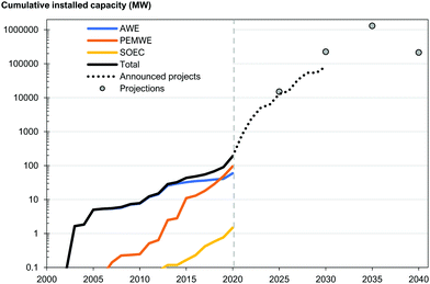 | ||
| Fig. 156 The cumulative installed capacity of modern hydrogen electrolysers, split by technology; with analysts’ projections for future market size. Historical data from Buttler and IEA,18,1891 and future trajectories from Aurora and the ETC.1890,1892 | ||
The potential markets for hydrogen are changing, as competition from other low-carbon technologies intensifies. In previous decades, passenger vehicles36 and home-heating systems1897 were thought of as the leading sectors to be served by hydrogen. Their prospects are now seen as waning, as battery electric vehicles1898 and electric heat pumps1899 have gained early ground in the transition away from fossil fuels.
Fig. 157 shows two examples of analysts’ expectations for where hydrogen will be competitive. The role of hydrogen is less contested for decarbonising specific industrial sectors (e.g., fertiliser and refining), heavy duty transport (shipping, aviation, trucks and buses) and especially for long-duration electricity storage.
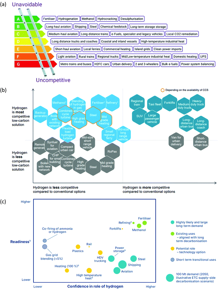 | ||
| Fig. 157 The perceived competitiveness of hydrogen across different market sectors. (a) The ‘hydrogen ladder’ popularised by Liebreich Associates,1900 which ranks applications from uncompetitive to unavoidable. (b) The competitiveness of hydrogen applications versus low-carbon and conventional alternatives, from the Hydrogen Council.1901 (c) The assessment of multiple potential uses of hydrogen performed by SYSTEMIQ for the ETC.1892 | ||
IRENA1903 and the ETC1892 and various market research firms discuss the main technology manufacturers. Some prominent examples are listed by technology in Table 16.
| AWE | PEMWE | SOEC | AEMWE |
|---|---|---|---|
| *Also manufacture alkaline electrolysers. | |||
| Asahi Kesei (Japan) | Cummins (US)* | Ceres (UK) | Enapter (Italy) |
| John Cockerill (France/Belgium) | Elogen (Germany) | Haldor Tøpsoe (Denmark) | |
| McPhy (France) | ITM Power (UK) | Sunfire (Germany) | |
| Teledyne (US) | NEL (Norway)* | Toshiba (Japan) | |
| Thyssenkrupp (Germany) | Siemens (Germany) | ||
| Tianjin Mainland (China) | |||
| Yangzhou Chungdean (China) | |||
14.2 Current capital cost of electrolysers
As with many areas in the energy sector, capex plays a defining role in the overall economic viability of hydrogen electrolysis. The cost of electrolytes will be critically important to their success, and competitiveness against other routes to producing hydrogen and other low-carbon fuels. The cost of electrolysers is relatively difficult to quantify for four reasons:(1) The technology is still at an early stage of commercial development (so data are not readily available);
(2) Costs differ substantially by technology due to design and materials requirements, as well as the maturity and scale of production;
(3) Prices vary strongly based on country of manufacture, with a prominent disparity between China and the rest of the world;
(4) Prices are changing rapidly as manufacturers increase their scale of production.
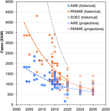 | ||
| Fig. 158 Capex costs of electrolysers, both historical and projections for alkaline, PEM and SOEC technologies. Data compiled from ref. 1903–1906. | ||
It is evident from Fig. 158 that costs have been rapidly falling in recent years. BNEF estimate that the capex of large-scale electrolysers fell by 40–50% in the five years to 2019.1907 Specifically, AWEs fell from $2000 to $1200 kW−1 over the period, while PEMWEs fell from $2800 to $1400 kW−1.
Electrolysis systems consist of more than just the electrolyser stack (Fig. 159). Ancillary equipment, known as the balance-of-plant (BoP) include the power conditioning (transformer and rectifier to condition the DC supply), water treatment (purification and heating), and hydrogen conditioning (separation, drying and pressurisation). All these components are mature technologies and used in a wide array of other industries and settings.
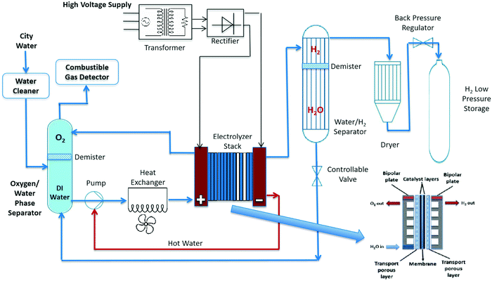 | ||
| Fig. 159 Typcial schematic of a PEMWE system. Source ref. 1908: | ||
The cost contribution of the electrolyser stack itself varies widely across literature, from 27% to 64%. Fig. 160 shows a range of study estimates of the contribution to capex from different electrolyser components.
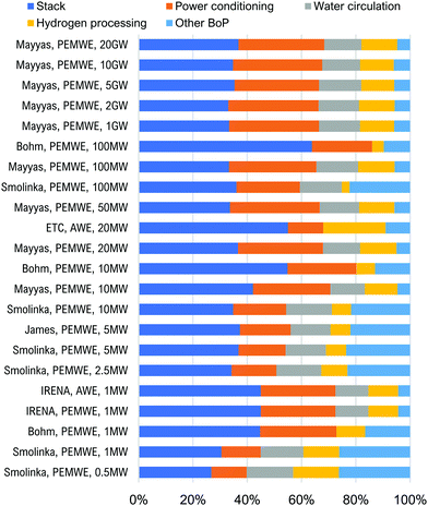 | ||
| Fig. 160 Comparison of the cost contribution of different electrolyser components. Data from ref. 1892, 1903, 1904 and 1909–1911. | ||
For example, IRENA calculates the stack contributes 45% of total system cost.1903 The remainder comes from the balance-of-plant components: power supply (28%), water circulation (12%), hydrogen processing (11%) and cooling (4%).1903 Mayyas and Mann similarly model the stack as contributing 40% of the total system cost,1909 with the BOP share mostly coming from the power supply. The share from balance-of-plant grows with scale of production, from 60% at 10 MW per year to 70% at 1 GW per year due to declining stack production costs.1909 IRENA1903 and ETC1892 also present breakdowns of AWE cost, giving 45% and 55% share respectively to the electrolyser stack. The majority of this cost is from manufacturing the diaphragm/electrode package, and the breakdown of BOP costs is similar to that for PEMWE.
Broadly as the capacity or production levels increase, the contribution from the stack increases. Lower cost estimates are associated with larger capacity installations: Fig. 161 shows a breakdown of system costs for different capacities. Whilst there are some cost reductions associated with the stack cost, their largely modular design lends less favourably to economies of scale. However, substantial cost reductions are achieved with the balance-of-plant, including hydrogen and water conditioning.
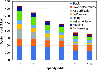 | ||
| Fig. 161 Component contribution to PEMWE electrolysis system cost at different capacities. Data from ref. 1904. | ||
There are very few publicly-available inventories for electrolysis stacks to understand the contributing components of the costs and it is likely that there is a large variation across manufacturers and scales of production. NREL suggest that AWE stacks cost 100 USD kW−1 (1 MW capacity, producing 10 to 20 units per year).
There are differences in the literature on the cost contribution from different stack elements see Fig. 162 for PEMWE. The catalyst-coated membrane is typically the largest cost (23 to 47% of total) due to use of iridium and platinum, whereas bipolar plates represent a high cost (9 to 51%) depending on the material used: higher costs associated with titanium plates, whereas lower costs may be from gold-coated steel manufacture.1908
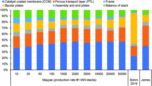 | ||
| Fig. 162 Estimates of cost contribution of different PEM electrolyser stack elements from three studies. Data from ref. 1909–1911. | ||
14.3 Future capital cost of electrolysers
Another complication in assessing the economics of hydrogen electrolysis is that costs are rapidly changing over time. New hydrogen production technologies are being developed and established technologies are undergoing continual refinement. Combined with the rapid scale-up of manufacturing, there is widespread expectation that current prices will continue to fall. This has been observed widely across the energy sector, with prominent examples being solar PV panels,1912 offshore wind farms,1913 electricity storage systems1914 and hydrogen fuels cells.1915 | (7.1) |
Experience curves are well established within the energy sector for modelling future product prices,1916,1917 and can be traced back to Wright's Law1918 from the 1930s. Solar photovoltaic panels are a prime example, with module prices falling by 23% for each doubling of capacity between 1976 and 2019.1919 Experience rates for energy technologies typically lie in the region of 5 to 30%.1914,1915,1920
Neij argues that modular technologies such as electrolysers should experience higher learning rates than monolithic products such as turbines.1921 Malhotra and Schmidt1922 show empirically that simple and standardised products such as solar panels or LED lights have higher learning rates (18–22%) than complex or customised/bespoke technologies such as conventional power plants or building insulation (3–5%). With electrolyser stacks being modular assemblies of standard repeated units, electrolysis would appear to fit the ‘simple and standardised’ group of technologies, which ought to experience the highest of these learning rates.
IRENA1903 and Saba et al.1923 survey previous studies of learning rates for electrolysers (Table 17). As there are relatively few studies to date, these learning rates are compared to estimates for hydrogen fuel cell systems, which “can be adapted also to electrolysers”.1923 Various studies have suggested that fuel cells have comparable learning rate in the region of 15 to 21%.1915,1924–1927
Böhm et al.1910 anticipate that the experience rate for electrolysers will decline over time as cumulative production increases (Fig. 163). This would occur because the core components of the electrolyser (catalyst layers, bipolar plates) are expected to have the higher learning rates than the generic components (flanges and pumps) and, as these core components become cheaper, their impact on the overall system's rate of cost decline will weaken.
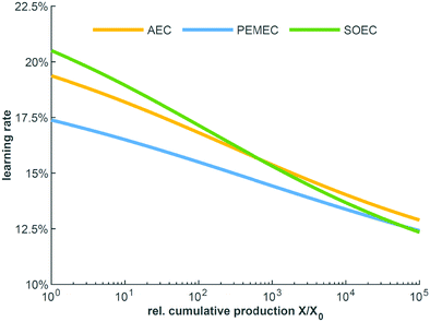 | ||
| Fig. 163 The development of experience rates for electrolysis stack modules as a function of cumulative production. Reproduced from Böhm et al.1910 | ||
These estimated learning rates can be combined with a forecast for the future market size (in terms of GW of capacity installed) to create future cost projections. Schmidt et al.1914 provides an example of this, projecting the price of alkaline electrolysers up to a cumulative capacity of 100 GW. When combined with a market projection, which is conservative in today's terms, this gives prices of $1300 kW−1 in 2030 and $970 kW−1 in 2040.
ETC1892 provides another example yielding much lower costs: attaining $160 kW−1 in 2030 and $80 kW−1 in 2040 in their ‘optimistic scenario’ (Fig. 164). This prediction uses an 18% learning rate, the same as in Schmidt et al., but yields much lower prices due to a lower reference price for electrolysis ($825 kW−1 in 2020 compared to $1340 kW−1 in ref. 1914) and more optimistic scenario for market growth (3300 GW installed by 2040 versus 270 GW in ref. 1914). This comparison highlights the sensitivity of experience curve analyses to their specific assumptions.
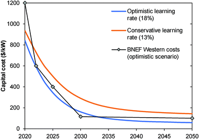 | ||
| Fig. 164 Cost projections from ETC based on optimistic and conservative learning rates for electrolysers (technology-neutral); compared to the BNEF scenario for costs outside of China. Data from ref. 1892. | ||
 | ||
| Fig. 165 Cost projections for alkaline and PEM electrolysers surveyed from the literature. Reproduced from Saba et al.1923 | ||
Bertuccioli et al.1906 provided trajectories for AWE and PEMWE costs out to 2030, using expert elicitation with 22 people from industry and academia. The expert estimates for AWE systems cost fell from $1100 kW−1 ($900–1300 range) in 2015 to $700 ($450–950 range) in 2030. For PEMWE, the estimates were $1.900 kW−1 ($1.450–2.350 range) in 2015 falling to $900 ($300–1.500 range) in 2030.
Similarly, Schmidt et al.1930 conducted an expert elicitation with ten people from industry and academia to gauge opinion on future cost reductions with both increased R&D funding and production scale-up (Fig. 166). These elicitations yielded similar ranges to those from Bertuccioli et al. albeit with narrower ranges in 2030. The experts estimated that increased R&D funding for water electrolysis could lower capital costs by 7–24% by 2030, with the weakest effect seen for AWE due to its maturity. Production scale-up was consistently thought to reduce costs by a further 22–29% across all technologies (Fig. 166).
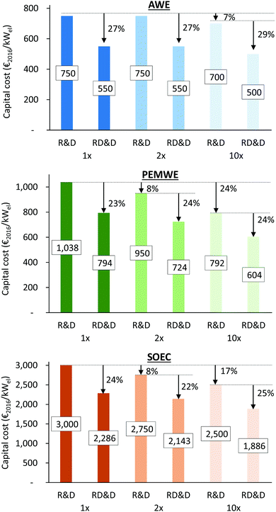 | ||
| Fig. 166 Estimated capital costs for water electrolysis in 2030 from expert elicitations conducted by Schmidt et al.1930 The median cost from all experts is given by technology (top to bottom). Each panel shows the relative impact of increased R&D funding (1x, 2x, 10x) by bars labelled R&D. This impact combined with production scale-up due to increased deployment is shown by bars labelled RD&D. Reproduced from ref. 1930. | ||
14.4 Drivers of cost reduction
Cost reductions are likely to be driven by a quickly maturing and growing market, namely: manufacturing scale-up, plant size increases, design improvements, and shifting production to cheaper world regions.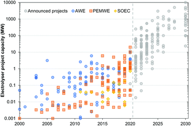 | ||
| Fig. 167 The size of individual electrolysis plants commissioned over the last two decades, and announced by companies for construction during the next decade. Compiled using data from IEA1891 and Aurora.1890 | ||
The impact of increasing plant size reduces system cost via economies of scale. As the capacity of the system increases the material and energy requirement typically reduces per unit of production (Fig. 168).
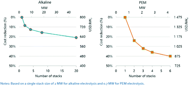 | ||
| Fig. 168 Estimate of cost reduction associated with plant size increases for AWEs and PEMWEs. Reproduced from the IEA.1889 | ||
Increased learning from manufacturing experience will help to de-risk system design and utilise finer margins (e.g., lower material requirements) to optimise cost, efficiency and lifetimes. Costs of capital and building were identified by Mayyas as being large contributors to low-volume-production of stack elements such as the catalyst-coated membrane, bipolar plates and porous transport layer (for PEMWE) and could be all but eliminated at large manufacturing volumes (of over 2000 units per year).1909
For PEMWEs, higher current densities can be achieved, from 0.6–2 up to >3 A cm−2via improved electrode design, catalyst coating and thinner membranes. Reducing the use of iridium and platinum with thinner coatings may reduce cost, as well as a replacement of titanium in bipolar plates and porous transport layers with a high-conductivity/stable coatings on low-cost materials such as steel. The rectifier, which converts AC current to DC, represents a large proportion of capex which could be reduced if a DC supply was used and required only a DC/DC converter.
For SOEC, capex reductions are achievable via reducing operating temperatures to ∼450 °C from reducing electrode polarisation resistance. This would help to avoid the requirement for high-temperature exotic materials and enable the use of lower cost materials such as stainless steel. So far, SOECs are still at an early stage of development and there is a need to prove lifetimes and improve cell and stack designs.
To illustrate the combined potential cost reductions associated with design improvements, increased plant size and manufacturing scale up, Fig. 169 shows an example cost reduction for a PEMWE system. The largest improvements are made from manufacturing economies of scale increasing production from 10 to 100 units per year, but total costs may be reduced from ∼$560 to 270 kW−1.
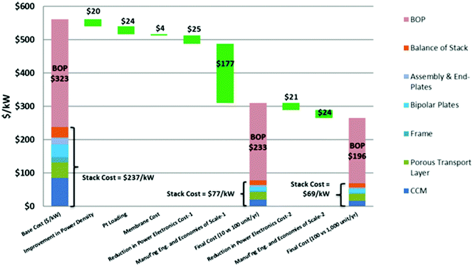 | ||
| Fig. 169 Future cost reductions for PEMWE systems across different production scales. Reproduced from Mayyas and Mann.1909 | ||
BNEF cite three reasons for lower costs in China: lower costs for raw materials and labour, higher utilisation rates for factories, and lower spending on R&D and marketing.1934 Others suggest that production quality is a factor, in particular lower durability and reliability.1935 BNEF announced that Chinese-made AWEs sold for $200 kW−1 in 2019, 83% less than Western-made systems at the time.1934 In addition, the lessons from COVID 19 could also spark a re-industrialising of Europe.
This was more bullish than other sources, as according to the IEA AWEs cost $500 kW−1. BNEF assumes that costs from Western manufacturers could converge with those from Chinese manufacturers over the coming decade.1934 Failing to become more competitive on cost could result in a declining market share for these manufacturers, and ultimately bankruptcy. Agora propose that EU-wide innovation support is key to the success of electrolysis manufacturing in Europe.1935
14.5 Levelised cost of hydrogen production
While capital costs are important, they are only one component of the overall lifetime cost. The total cost of construction and operation – and thus the cost of hydrogen produced – also depends primarily on the cost of electricity purchased, and on technical parameters such as the cell efficiency and lifetime.Just as renewable and conventional power stations can be summarised by their levelised cost of energy (LCOE), the total cost of electrolysis can be summarised by the levelised cost of hydrogen (LCOH), also known as the levelised cost of gas (LCOG). This quantifies the total cost of production discounted over the system's lifetime, per unit of hydrogen generated (e.g., $ kg−1 or $ MW−1)
The LCOH provides a fair comparison by factoring in all technical and economic parameters: capital cost, operating costs, production efficiency, system lifetime, performance degradation and the cost of energy used. This concept can be used to explore important trade-offs, for example the use of better materials to increase the durability or efficiency of the system. This will likely increase the capital cost but reduce operating costs due to less maintenance required or less electricity needing to be purchased.
As with the levelised cost of storage (LCOS), there are various definitions employed which may include or exclude relevant parameters such as end-of-life disposal of the system, electrolyser stack replacement or capacity degradation over the lifetime.1936
The levelised cost of hydrogen1936 is given by:
 | (7.2) |
The latter is governed by the producing technology and the regional environment. A key distinction is whether electricity is purchased from a region's power grid or directly from a low-carbon or renewable generation source. Wholesale power market prices vary around the world due to differences in generation mix and the fuels used, emissions prices and taxation; but a primary driver in most markets is the global or regional price of fossil fuels.1937,1938 Electricity prices also see substantial short-term and long-term volatility, varying diurnally with demand and availability of renewable energy, and seasonally with fluctuating fossil-fuel prices.1939,1940
Many studies1889,1892,1903,1936 consider power prices in the range of $40–60 MW−1 h−1, as this broadly reflects the long-term average seen across Europe and North America, or $20 MW−1 h−1 as a sensitivity to reflect the trend of power prices falling as the share of renewable energy increases.1941Fig. 170 shows the impact of power price on the cost of delivered hydrogen.
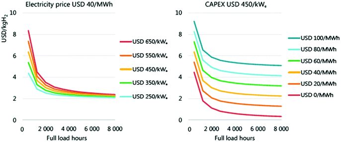 | ||
| Fig. 170 Hypothetical future levelised cost of hydrogen production from electrolysers as a function of capital cost (left) and electricity cost (right). Calculations assume a discount rate of 8% and efficiency of 69% (LHV). Reproduced from IEA.1889 | ||
Given the role of water electrolysis in decarbonising energy systems, there is a key focus on ‘green hydrogen’ produced solely from renewable electricity. The cost of electricity generation from solar PV has fallen by a factor of 7 between 2010 and 2020, and for wind it has halved over the same period.1912 This is primarily due to falling capital costs which are experienced worldwide, but there are also strong regional variations due to the underlying productivity of wind and solar farms.1942,1943
Every region has different solar and wind generation characteristics which would affect hydrogen production and costs if installed (Fig. 171). For regions with high-capacity factors, the cost of electricity generation is cheap, reducing the cost of hydrogen production.
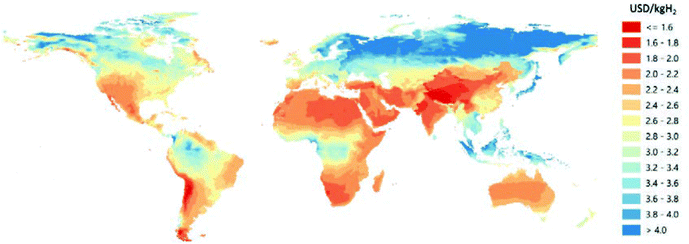 | ||
| Fig. 171 Modelled cost of hydrogen production using solar PV or wind as electricity source. Reproduced from IEA.1889 | ||
If green hydrogen is produced from hard-linking wind or solar PV with an electrolyser, the lowest cost hydrogen production requires consideration of the trade-off between installed solar/wind capacity and installed electrolysis capacity: this governs the average utilisation rate of the electrolyser.
For a 1 MW electrolyser system, 1 MW of installed wind capacity would supply an average of 400 kW (with an average capacity factor of 40%). The utilisation rate of the electrolyser would be the same as the capacity factor of the wind. To achieve higher electrolyser utilisation and to decrease the levelised electrolyser capex, higher quantities of wind must be installed. The increase in utilisation will be governed by the wind output curve and installing extra capacity will yield an oversupply of electricity at some points during the year. This oversupply could be exported if there is an available connection or used on-site, otherwise it would have to be curtailed. Consequently, there may be a trade-off between lowering cost from increased electrolyser utilisation and increasing cost from curtailed wind capacity.
IRENA projects that the levelised cost of gas could fall from around $5 kg−1 today ($2.70–6 kg−1 range depending on conditions) to $1 kg−1 in the future.1903 Most of this saving comes from two key interventions: an 80% reduction in electrolyser capex (from $750 to $150 kW−1) which saves $1.80 kg−1; and a halving of electricity input cost (from $53 to $20 MW−1 h−1) which saves $1.40 kg−1.1903 Similarly, ETC models hydrogen costs in Europe at being €5.10 kg−1 today (assuming $780 kW−1 capital costs).1892 This could fall to €3.60 kg−1 in future with 500 TW h (10 Mt) annual demand for hydrogen, and further to €1.70 kg−1 with 1,100 TW h (22 Mt) annual demand. Again, the main savings come from reducing capital costs ($1.30 kg−1) and abundant cheap renewable electricity ($1.10 kg−1).1892
Agora is more optimistic, suggesting hydrogen could cost $2.60 kg−1 today when using PV in North Africa as the electricity source.1935 This cost could fall to $1.90–2.20 kg−1 in 2025, and further to $1.30 in 2030 if there is convergence towards Chinese manufacturing costs ($115 kW−1), or to $1.90 kW−1 with IEA's assumption for minimum capex.1935 The influence of the key drivers is summarised in Fig. 172.
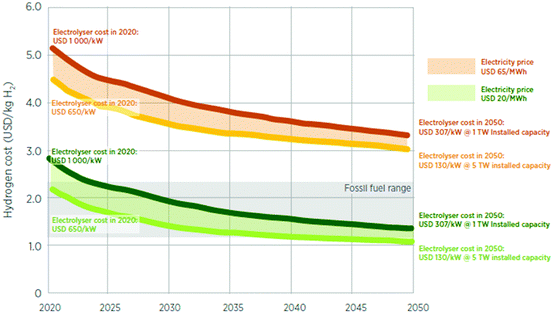 | ||
| Fig. 172 Cost projections for green hydrogen production over time, as a function electrolyser capital cost and electricity price. Reproduced from IRENA.1903 | ||
Academic studies similarly estimate hydrogen production costs of $4.50 kg−1![[thin space (1/6-em)]](https://www.rsc.org/images/entities/char_2009.gif) 1945 when using offshore wind, and $5.00–6.10 kg−1 when using renewable energy;1946 in niche applications, although not yet for industrial-scale $3.48 kg−1.1905 Provided that recent market trends continue the hydrogen production costs are assumed to reduce to $2.7 kg−1. These scenarios also agree with current industry announcements. Areva H2Gen report a cost of $3.90 kg−1 from a fully-utilised 1 MW PEMWE system (8000 operating hours per year) at a power price of $55 MW−1 h−1.1947 Enapter whises to reduce the cost of hydrogen from their household-scale (2.4 kW) AEMWEs from $7.60 in 2020 to $1.60 kg−1 in 2030, plus around $3 kg−1 for electricity consumed.1947
1945 when using offshore wind, and $5.00–6.10 kg−1 when using renewable energy;1946 in niche applications, although not yet for industrial-scale $3.48 kg−1.1905 Provided that recent market trends continue the hydrogen production costs are assumed to reduce to $2.7 kg−1. These scenarios also agree with current industry announcements. Areva H2Gen report a cost of $3.90 kg−1 from a fully-utilised 1 MW PEMWE system (8000 operating hours per year) at a power price of $55 MW−1 h−1.1947 Enapter whises to reduce the cost of hydrogen from their household-scale (2.4 kW) AEMWEs from $7.60 in 2020 to $1.60 kg−1 in 2030, plus around $3 kg−1 for electricity consumed.1947
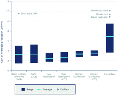 | ||
| Fig. 173 Levelised cost of hydrogen production from different production technologies. Reproduced from ref. 1948 and 1949. | ||
However, the cost of electrolysing hydrogen and then converting it back to electricity is favourable compared to other energy storage technologies. Schmidt et al.1936 calculated the levelised cost of storage for several technologies (including electrochemical, mechanical, pumped hydro) across all major power systems applications, and projected these into the future based on experience rates and market growth scenarios. The most cost-effective storage technology for the full spectrum of applications is shown in Fig. 174.
Hydrogen storage (comprising electrolysis and a fuel cell) was found to be especially effective for long-duration seasonal storage due to its technical characteristics. At present, hydrogen is the lowest-cost technology with more than one month (7000 h) of discharge time; and in regions of the world which cannot use pumped hydro or underground compressed air storage, hydrogen is the lowest-cost solution for discharge durations beyond one day. The operating window in which hydrogen is cost competitive is expected to broaden over time as its costs should fall more rapidly than those for mature pumped hydro.
15 Summary and outlook
In the present contribution, water electrolysis is addressed in a comprehensive manner, with insights spanning from textbook knowledge to the latest scientific strategies and industrial developments. The contribution bases its argumentation on thorough and relevant literature on the topic, and details key aspects of water electrolysis in 14 sections.Firstly, Section 2 gave insight into the fundamentals of the two reactions that take place in water electrolysers: the HER at the negative electrode (where H2 is produced) and the OER at the positive electrode (where O2 is produced). The basic mechanisms of these reactions are given, with special insights into their limiting steps, which enables to pave the way to optimised electrocatalysts discovery and better electrode engineering.
Section 3 overviewed the various water electrolyser technologies; while high-temperature systems (solid oxide electrolyser cell (SOEC), proton conducting ceramic electrolyser cell (PCCEC)) are in-principle more efficient, they are also submitted to harsh materials constraints, which requires a wealth of engineering optimisation and until now prevented their commercialisation. Molten carbonate electrolyser cell (MCEC), although less studied from a scientific perspective (the materials issues seem handleable), received increasing attention on the industrial side recently, and could become commercial in a close future. Low-temperature water electrolysers are now commercial. Alkaline water electrolyser (AWE) are commercialised since decades and AWE systems are robust and do not depend on platinum group metals, but are also less intensive and efficient, incompatible with intermittent operation and H2 compression, unlike their proton exchange membrane counterparts (PEMWE). The latter enable better performances, but are limited by the costs of their constitutive materials. Last, anion exchange membrane water electrolysers (AEMWE), although still at their infancy, could combine the interests of AWE (no PGM catalysts) and of PEMWE (thin membrane for good gas separation, compatibility with intermittency and H2 compression); intense research efforts are presently devoted to PEMWEs and AEMWEs.
Section 4 listed key performance indicators (KPI) and technology targets for these systems, with special emphasis to low-temperature water electrolysers, which have more chance to meet wide-scale commercialisation in the next decade.
Section 5 emphasised the need of research in terms of materials science and electrochemistry for the various technologies evaluated in this review. Then, Sections 6–8 focused on practical research efforts for the various families of electrode materials that are (or could be) employed in low-temperature water electrolysers.
Section 6 starts by a short review of state-of-the-art PGM-based catalysts for the HER and OER. It emphasises the fact that, if their today's performances are acceptable, the target is to keep these performances at smaller PGM-loading, which can be achieved by downsizing the particles/crystallites size, and/or alloying the active material (Pt, Ir) with less costly elements, and/or supporting them on stable conductive substrates (two strategies which may influence the activity and stability of the obtained composite, in good or in bad). The poor abundance of PGM in the Earth's crust motivates the search for alternative (non-PGM-based) catalysts.
Section 7 reported about the very comprehensive literature dealing with PGM-free based HER and OER electrocatalysts; obviously, many of the references are related to materials for AWEs (and AEMWEs), but some of it also addresses PEMWEs. Among this rich literature, some concerns metal dioxides as OER and HER electrocatalysts (PbO2 and MnO2 as electrode material for oxygen evolution). Metal oxides in the perovskite or spinel structure as OER and HER electrocatalysts are also surveyed, as well as transition metal layered double hydroxide OER catalysts for alkaline electrolytes. Finally, a rather recently-investigated class of non-PGM materials will be evaluated as well: steel-based electrodes for both HER and OER electrocatalysis. All these materials (and in particular the transition metal layered double hydroxides and steels) will have a chance to be employed in future A(EM)WE systems. As far as PEMWEs are concerned, durability issues when using non-PGM are a bit harder to handle, and these materials should not be used in such systems in the next decade.
Because metals in general may experience scarcity if used at the large scale (even for the non-PGM) mentioned in Section 7, Section 8 addressed the intense research efforts of the scientific community into metal-free (or with ultra-small metal content) HER and OER electrocatalysts. Catalysts with a carbon skeletal structure are dealt with first, and then heteroatom-doped carbons for OER, bifunctional catalysts and catalysts with a carbon-nitrogen skeletal structure, such as carbon nitride-graphene composites-based catalysts with high N content. Although not deployed industrially, these materials may be part of the solution in the long-term.
Since the performance of a given catalyst in a real water electrolysis cell depends not only on its intrinsic activity but also (and very importantly) on the way it is used in gas generating electrodes, Section 9 provides detailed basic concepts of 2D and 3D-electrode preparation. The section highlighted manners to elaborate HER and OER catalysts, but also how to prepare electrodes and membrane electrode assemblies to be used in practical systems.
Molecular compounds for HER and OER is a topic where the research community is very productive. Inspired by nature, these materials have some assets (selectivity, turnover frequency), but the poor accessibility of their active site and low durability are two real challenges to their practical usage. They were surveyed in Section 10.
Section 11 reviewed methods to characterise both electrocatalysts materials and electrodes. These span from two-electrode cell characterisations of the full electrolysis cell (possible in real system), three-electrode cell characterisations of individual electrodes (usually performed at the laboratory scale in more model conditions); importantly, physicochemical techniques coupled to electrochemistry are also addressed, the literature being extremely rich on the subject, because these are mandatory characterisations to unveil how water electrolysers and their core materials operate, a prerequisite to mechanisms determination and materials/structures optimisation.
Section 12 then evaluated how externally-applied fields like mechanical stirring, magnetic field and ultrasound could enhance water splitting, these strategies usually being applied for low-temperature cells.
Finally, because purified-water is by far not the most abundant and easily-available on the planet, Section 13 focused on water splitting from non-pure water (saline water, seawater, neutral water pH, wastewater), while Section 14 provided a solid cost-analysis.
The wealth of information contained in this review shows how dynamic research is on the topic of water electrolysis. It makes clear that materials science and electrochemistry are at the basis of new discoveries of more efficient electrode/electrolyte materials, but one must not lose sight that engineering of these materials is also mandatory to turn them into long-lasting efficient electrodes for water splitting.
Outlook
The recent abnormal climatic episodes experienced in summer 2021 in Germany/Belgium (extreme flooding) and USA/Canada (severe droughts and subsequent gigantic forest fires) made even clearer the sad reality of major climate disturbance on our planet. It makes no doubt it is caused by global warming, itself related to major release of greenhouse gases in the atmosphere since the industrial revolution. The strategy to mitigate this issue is clear: the greenhouse gases emissions must be (very) significantly cut. One manner to do so is to rely more on renewable energies, which implies that renewable electricity is efficiently stored at the large scale and the long-term. Power-to-hydrogen (and then conversion of hydrogen into electricity in fuel cells) is an obvious strategy to that goal.Water electrolysis when driven by renewable electricity represents a green, i.e., a CO2 footprint free power-to-hydrogen route. To effectively counteract global temperature rise, greenhouse gas reducing techniques must be enforced internationally or, in other words, water electrolysis will only make a substantial contribution to the reduction of greenhouse gases emissions if it is widely deployed. The cross-border application of water electrolysis technologies however presupposes that it can be adapted to the different circumstances of the countries (costs for electricity, global solar radiation, availability of wind-active centers, availability of water). A technology always has the best chance of asserting itself if it is cheaper than competing processes, i.e., in this case water electrolysis needs to become more economical than processes that are based on the exploitation of oil, coal and natural gas, this being completely independent on the fact that the last-mentioned methods counteract the goal of reducing the emission of greenhouse gases. The economy of water electrolysis is not only determined by the physical-chemical efficiency based on the cell voltage necessary to end up in a certain current density in combination with the charge to gas conversion rate. In addition to the durability of the electrode material in particular and the overall maintenance costs, the acquisition costs due to the electrode materials and the device design also play a role. Nevertheless, optimization of water electrolysis electrodes, i.e., the improvement of OER and HER electrocatalysts and the intensification of the electrocatalyst-conductive support interaction is and remains amongst the most important adjustment screw that needs to be turned in order to make a significant leap towards highly efficient electrocatalytic water splitting.
Some of the authors have worked extensively on perovskite-based OER electrode materials. Many recently published articles report on composite materials containing perovskite as the active component for the OER. Although much research effort has been devoted to the development of OER-active perovskites, we believe that the development of composites that support perovskites as the OER electrocatalyst and ensures an intense, synergistic interaction between the electrocatalyst and the conductive support or at the electrocatalyst/interlayer interface, is a sensible strategy worth pursuing. This certainly also applies to spinel-based water-splitting electrodes. More complex spinel-containing hybrid materials have recently emerged as highly efficient supported OER catalysts. Further strategies to increase the number of OER active sites as e.g., cations filling of unoccupied interstices leading to cationic misalignment need to be implemented into a broader spectrum of spinel for OER electrocatalysis. In addition, spinel-type materials are promising HER supporting materials giving them bifunctionality.
A more thorough investigation of effects that occur when nonmetals such as S, P are incorporated into transition-metal based spinels could lead to a more informed knowledge-based development of useful material design strategies and should result in more HER-active spinel's. However, currently metal pnictides, metal carbides, metal borides, metal chalcogenides are more competitive HER-promoting electrocatalysts; binary borides and carbides are among the best binary HER electrocatalysts in terms of both activity and durability. Among the materials that consist of metal elements and non-metal elements (main groups 3, 4, 5 and 6), hybrid composed phases with coexisting metallic and a non-metal rich phase belong to the absolute bench mark species. This has been shown, for example, for molybdenum nitride-based electrode materials. This concept should be extended and successfully transferred to other metal/nonmetal compounds. Besides the further understanding and improvement of well-established metal/non-metal based HER active compounds we recommend the more intensive investigation of up to now less investigated electrocatalytic active metal/non-metal composed compounds as for instance transition metal tellurides. From a theoretical point-of-view tellurides (in general) should not be less active than the lighter homologues of the sixth main group.
Steels have proven to be outstandingly efficient and outstandingly durable as electrode materials for water electrocatalysis. Recently, suspension-based approaches have emerged; e.g., it has been found that transition metal oxides are reasonable additions to sulfuric acid-based electrolytes. Currently, however, the amount of solid material that needs to be added to the clear electrolyte to have the desired effect, i.e., to significantly reduce the overpotential required to achieve a given current density is high and is about 30 g per 100 mL of electrolyte. This means that adapting to current electrolyzer technologies is almost impossible. Therefore, scientists should aim to significantly reduce the required amount of added oxidic solid compound.
Generally, non-metal based electrocatalysts can still not compete with metal-based ones with respect to efficiency for OER or HER electrocatalysis. The improvement of the contact between conductive support and the periphery composed of the real catalytic active phase seems to be a promising route to increase the catalytic activity. Besides doping of the conductive host lattice, e.g., graphitic carbon nitride matrix with P or S or P and S was already found to be an effective way to manipulate electronic structure and electrochemical properties which means not only the increased catalytic efficiency but also the reduction of the intrinsic susceptibility for carbon to corrode in OER regime.
The authors think that the embedding of molecular compounds into conductive support might indeed become a promising strategy to result in effective (heterogeneous) water electrocatalysis. Thus, whenever molecular species are used in solid-state electrocatalysis, at least reasonable catalytic efficiency can be achieved. However, to date, molecular compounds that enable homogeneous water catalysis have not been able to represent a viable strategy to achieve competitive current densities at moderate overpotentials.
Besides the optimisation of the electrode materials there are several methods for reducing the total overpotential and total Ohmic resistance in water electrolysis, for example, by increasing the electrolyte movement (by using gravity, centrifugal acceleration field, mechanical stirring, magnetic field; employing ultrasound at the gas-evolving electrodes and electrolyte). These are promising strategies to further increase the efficiency of water electrolysis and in particular the combination of externally applied fields with newly developed state-of-the-art electrode materials and cell designs should be further investigated.
Among electrolyser technologies, in particular AEMWE is very promising in terms of total cost of ownership. Although this technique has been intensively investigated lately, studies on cell performance stability remain rare. The existing studies that comprise performance stability tests for AEMWE at constant current density showed a substantial reduction in already about 100 hours after commissioning, probably owing to chemical degradation of the anion conducting polymers at high pH value. Thus, on the one hand, further tests examining the durability of the membrane in long-term use are urgently needed, and further improvement of the membrane against base-related degradation must be tackled. Also, the interfacial contact between the anion-exchange membrane (AEM) and the catalytic layers need to be further optimized, as it can simply not be prepared by coupling conventional AWE electrodes with an AEM. These materials and chemical-engineering aspects should without any doubt be seriously handled by the research community in the future, if one wants to have AEMWEs at large for the storage of renewable electricity. The same applies as well for PEMWEs, the goal of engineering being in that case to lower the amount of PGM used in the electrodes and to reach longer service-life in real (renewable electricity storage) operation.
Finally, and although this has not been amongst the primary points of focus of this review, working on system aspects, balance-of-plant and control and command of the water electrolyzer (regardless of the technology used) is not less important.
We encourage the scientists involved in this striking field of research to avoid taking wrong turns. To give an example, water purification techniques have been very well established and with regard to economic criteria, direct saltwater electrolysis is almost always surpassed by a combination of the latest deionization technology plus alkaline water electrolysis (AWE) or proton exchange membrane (PEM) water electrolysis. The authors therefore think that further investing resources in exploration of the direct electrolysis of seawater is at least worthy of discussion.
This shows that, in the present times where hydrogen is called to become a major energy vector in our societies, the research community as a whole as multiple challenges to handle, which should find their solutions be a clever coupling between complementary multidisciplinary approaches spanning from basic materials sciences (electrocatalysis, polymer chemistry and physics), chemical and materials engineering all the way to mechanical and electrical engineering. This is the only solution by which the complex systems that are water electrolyzers will become sufficiently technologically-advanced and economically-viable to be deployed at large (and coupled to fuel cells or other hydrogen-using devices), an endeavor to lower our greenhouse gases emissions.
Author contributions
MC (particularly) wrote Section 2 + Section 6 (partly) as well as Sections 11 and 15. He edited the manuscript as a whole in detail. BGP wrote Section 12 as well as Section 6. MZB wrote Section 3.2.1 and particularly edited Section 2. DD wrote Section 5.2 and edited the manuscript as a whole in detail. FD wrote Section 7.4. JD evaluated Sections 2 and 6 as well as Sections 11 and 15. PM wrote Sections 3, 9 and 5.3 and edited the manuscript as a whole in detail. RDB partly wrote Section 1 and edited the manuscript as a whole in detail. ME wrote Section 2. IS wrote Section 14 and he edited the manuscript as a whole in detail. He was, in addition responsible for finalizing the main text and SI files prior submission. PB wrote/edited Section 14. YSH wrote Section 1 and basically edited sections dedicated to the materials parts. HS wrote Sections 7.1, 7.2, 7.3, 7.5, 7.6, 8, 10, 13 and partly contributed to Section 2.Conflicts of interest
There are no conflicts to declare.Acknowledgements
D. R. D. time in this work was funded by the Mauerberger Foundation Fund (MFF); by the Nancy & Stephen Grand Technion Energy Program (GTEP); and by the Planning & Budgeting Committee/ISRAEL Council for Higher Education (CHE) and Fuel Choice Initiative (Prime Minister Office of ISRAEL), within the framework of “Israel National Research Center for Electrochemical Propulsion (INREP)”. M. C. and J. D. acknowledge funding from the National Research Agency, in the frame of the Hy-WalHy project (ANR-1-CE05-0017). I. S. was funded by the European Union's Horizon 2020 research and innovation programme under grant agreement No. 837089.References
- “Sir David Attenborough: We Must Act on Population”. Population Matters. 5 October 2018. Retrieved 1 December 2019.
- J. Gregus and J. Guillebaud, Eur. J. Contracept. Reprod. Health Care, 2020, 25, 409–416 CrossRef PubMed.
- J. Bongaarts and B. C. O’Neill, Science, 2018, 361(6403), 650–652 CrossRef CAS PubMed.
- M. Dincă, Y. Surendranath and D. G. Nocera, Proc. Natl. Acad. Sci. U. S. A., 2010, 107, 10337–10341 CrossRef PubMed.
- P. Poizot and F. Dolhelm, Energy Environ. Sci., 2011, 4, 2003–2019 RSC.
- R. J. Deetz, J. N.-H. Reek and B. C.-C. van der Zwaan, Energy Environ. Sci., 2018, 11, 1653–1669 RSC.
- M. Beaudin, H. Zareipour, A. Schellenberglabe and W. Rosehart, Energy Sustain. Dev., 2010, 14, 302 CrossRef.
- I. Staffell and S. Pfenninger, Energy, 2018, 145, 65–78 CrossRef.
- A. Hauer, J. Quinnell and E. Lavemann, Energy Storage Technologies – Characteristics, Comparison, and Synergies, in Transfer to Renewable Energy Systems, ed. D. Stolten and V. Scherer, Wiley-VCH Verlag GmbH & Co., Weinheim, Germany, 2013, ch. 27, pp. 555–577 Search PubMed.
- The Future of Hydrogen: Seizing Today's Opportunities, International Energy Agency, Paris, France, June 2019. https://www.iea.org/reports/the-future-of-hydrogen.
- A. Kudo and Y. Miseki, Chem. Soc. Rev., 2009, 38, 253 RSC.
- M. G. Walter, E. L. Warren, J. R. McKone, S. W. Boettcher, Q. Mi, E. A. Santori and N. S. Lewis, Chem. Rev., 2010, 110, 6446 CrossRef CAS PubMed.
- A. J. Bard and M. A. Fox, Acc. Chem. Res., 1995, 28, 141 CrossRef CAS.
- T. R. Cook, D. K. Dogutan, S. Y. Reece, Y. Surendranath, T. S. Teets and D. G. Nocera, Chem. Rev., 2010, 110, 6474–6502 CrossRef CAS PubMed.
- M. W. Kanan, Y. Surendranath and D. G. Nocera, Chem. Soc. Rev., 2009, 38, 109–114 RSC.
- V. Artero, M. Chavarot-Kerlidou and M. Fontecave, Angew. Chem., Int. Ed., 2011, 50, 7238–7266 CrossRef CAS PubMed.
- K. Zeng and D. Zhang, Prog. Energy Combust. Sci., 2010, 36, 307–326 CrossRef CAS.
- A. Buttler and H. Spliethoff, Renewable Sustainable Energy Rev., 2018, 82, 2440–2454 CrossRef CAS.
- U.S. Energy Information Administration, International Energy Outlook 2019.
- M. Bernt, A. Hartig-Weiß, M. F. Tovini, H. A. El-Sayed, C. Schramm, J. Schröter, C. Gebauer and H. A. Gasteiger, Chem. Ing. Tech., 2020, 92, 31 CrossRef CAS.
- J. R. Varcoe, P. Atanassov, D. R. Dekel, A. M. Herring, M. A. Hickner, P. A. Kohl, A. R. Kucernak, W. E. Mustain, K. Nijmeijer, K. Scott, T. Xu and L. Zhuang, Energy Environ. Sci., 2014, 7, 3135–3191 RSC.
- H. Schäfer and M. Chatenet, ACS Energy Lett., 2018, 3, 574–591 CrossRef.
- C. Lamy and P. Millet, J. Power Sources, 2020, 447, 227350 CrossRef CAS.
- C. Wei, R. R. Rao, J. Peng, B. Huang, I. E.-L. Stephens, M. Risch, Z. J. Xu and Y. Shao-Horn, Adv. Mater., 2019, 31, e1806296 CrossRef PubMed.
- Y. Lee, J. Suntivich, K. J. May, E. E. Perry and Y. Shao-Horn, J. Phys. Chem. Lett., 2012, 3, 399–404 CrossRef CAS PubMed.
- B. M. Tackett, W. Sheng and J. G. Chen, Joule, 2017, 1, 253–263 CrossRef CAS.
- E. Fabbri, M. Nachtegaal, T. Binninger, X. Cheng, B. J. Kim, J. Durst, F. Bozza, T. Graule, R. Schaublin, L. Wiles, M. Pertoso, N. Danilovic, K. E. Ayers and T. J. Schmidt, Nat. Mater., 2017, 16, 925–931 CrossRef CAS PubMed.
- B. Han, K. A. Stoerzinger, V. Tileli, A. D. Gamalski, E. A. Stach and Y. Shao-Horn, Nat. Mater., 2017, 16, 121–126 CrossRef CAS PubMed.
- C. Niether, S. Faure, A. Bordet, J. Deseure, M. Chatenet, J. Carrey, B. Chaudret and A. Rouet, Nat. Energy, 2018, 3, 476–483 CrossRef CAS.
- Y. Zhu, G. Chen, Y. Zhong, Y. Chen, N. Ma, W. Zhou and Z. Shao, Nat. Commun., 2018, 9, 2326 CrossRef PubMed.
- V. Gatard, D. De Masi, R. Chattot, I. M. Marin, J. M. A. Revert, P. F. Fazzini, T. Encinas, V. Martin, S. Faure, J. Deseure, J. Carrey, B. Chaudret and M. Chatenet, Electrocatalysis, 2021, 11, 567–577 CrossRef.
- M.-T. Dinh Nguyen, A. Ranjbari, L. Catala, F. Brisset, P. Millet and A. Aukauloo, Coord. Chem. Rev., 2012, 256, 2435–2444 CrossRef CAS.
- E. Pizzutilo, S. Geiger, J. P. Grote, A. Mingers, K. J.-J. Mayrhofer, M. Arenz and S. Cherevko, J. Electrochem. Soc., 2016, 163, F1510–F1514 CrossRef CAS.
- S. Abbou, R. Chattot, V. Martin, F. Claudel, L. Solà-Hernández, C. Beauger, L. Dubau and F. Maillard, ACS Catal., 2020, 10, 7283–7294 CrossRef CAS.
- J. Kurtz, S. Sprik, G. Saur and S. Onorato, Fuel Cell Electric Vehicle Durability and Fuel Cell Performance, National Renewable Energy Laboratory (NREL), Denver, Colorado Technical Report NREL/TP-5400-73011, March 2019. https://www.nrel.gov/docs/fy19osti/73011.pdf.
- B. G. Pollet, S. S. Kocha and I. Staffell, Curr. Opin. Electrochem, 2019, 16, 90–95 CrossRef CAS.
- E. Price, Johnson Matthey Technol. Rev., 2017, 61, 47–51 CrossRef.
- EUR 29267 EN, JRC107053, in EU Harmonised Test Procedure: Electrochemical Impedance Spectroscopy for Water Electrolysis Cells, ed. T. Malkow, A. Pilenga and G. Tsotridis, Publications Office of the European Union, Luxembourg, 2018 DOI:10.2760/67321.
- EUR 29300 EN, JRC112082, in EU Harmonised Terminology for Low Temperature Water Electrolysis for Energy Storage Applications, ed. G. Tsotridis and A. Pilenga, Publications Office of the European Union, Luxembourg, 2018 DOI:10.2760/014448.
- H. Schäfer, D. M. Chevrier, K. Kuepper, P. Zhang, J. Wollschläger, D. Daum, M. Steinhart, C. Hess, U. Krupp and K. Müller-Buschbaum, Energy Environ. Sci., 2016, 9, 2609–2622 RSC.
- H. Schäfer, K. Küpper, K. M. Müller-Buschbaum, D. Daum, M. Steinhart, J. Wollschläger, U. Krupp, M. Schmidt, W. Han and J. Stangl, Nanoscale, 2017, 9, 17829–17838 RSC.
- J. Durst, A. Siebel, C. Simon, F. Hasché, J. Herranz and H. A. Gasteiger, Energy Environ. Sci., 2014, 7, 2255–2260 RSC.
- C. H. Hamann and W. Vielstich, Elektrochemie, Wiley-VCH Verlag GmbH & Co., Weinheim, Germany, 4th edn, 2015 Search PubMed.
- J. Huang, S. Chen and M. Eikerling, J. Chem. Theory Comput., 2021, 17, 2417–2430 CrossRef CAS PubMed.
- R. Tesch, P. M. Kowalski and M. H. Eikerling, J. Phys: Condens. Matter, 2021, 33, 444004 CrossRef CAS PubMed.
- H. Jun, A. Malek, J. Zhang and M. H. Eikerling, J. Phys. Chem. C, 2016, 120, 13587–13595 CrossRef.
- J. Huang, X. Zhu and M. Eikerling, Electrochim. Acta, 2021, 393, 139019 CrossRef CAS.
- H. Jun, J. Zhang and M. Eikerling, Phys. Chem. Chem. Phys., 2018, 20, 11776–11786 RSC.
- D. M.-F. Santos, A. C. Cesar, J. L. Sequeira and J. L. Figueiredo, Quim. Nova, 2013, 36, 1176–1193 CrossRef CAS.
- C. Mittelsteadt, T. Norman, M. Rich and J. W. Giner, PEM Electrolyzers and PEM Regenerative Fuel Cells Industrial View, in Electrochemical Energy Storage for Renewable Sources and Grid Balancing, Elsevier, Waltham, MA, 2015, ch. 11, pp. 159–181 Search PubMed.
- J. O.'M. Bockris and A. K.-N. Reddy, Modern Electrochemistry 1, Plenum Publishing Corporation, New York, 1977, ch. 1–4, vol. 1, pp. 1–460 Search PubMed.
- J. O.'M. Bockris, A. K.-N. Reddy and M. Gamboa-Aldeco, Modern Electrochemistry 2A, Kluwer Academic/Plenum Publishers, New York, 2nd edn, 2018, ch. 6–7, pp. 771–1216 Search PubMed.
- M. Eikerling and A. A. Kulikovsky, Polymer Electrolyte Fuel Cells – Physical Principles of Materials and Operation, CRC Press, 2014 Search PubMed.
- M. Z. Bazant, Acc. Chem. Res., 2013, 46, 1144–1160 CrossRef CAS PubMed.
- H. A. Bandal, A. R. Jadhav and H. Kim, J. Alloy Comp., 2017, 726, 875–884 CrossRef CAS.
- R. Phillips, W. J. F. Gannon and C. W. Dunnill, Alkaline Electrolysers, Electrochemical Methods for Hydrogen Production, The Royal Society of Chemistry, 2020, ch. 2, pp. 28–58 Search PubMed.
- J. Schillings, O. Doche, M. Tano Retamales, F. Bauer, J. Deseure and S. Tardu, Int. J. Multiph. Flow, 2017, 89, 92–107 CrossRef CAS.
- A. Lasia, Int. J. Hydrogen Energy, 2019, 44, 19484–19518 CrossRef CAS.
- S. Anantharaj, S. R. Ede, K. Karthick, S. S. Sankar, K. Sangeetha, P. E. Karthik and S. Kundu, Energy Environ. Sci., 2018, 11, 744–771 RSC.
- Y. Shi and B. Zhang, Chem. Soc. Rev., 2016, 45, 1529–1541 RSC.
- E. Fabbri, A. Habereder, K. Waltar, R. Kötz, T. J. Schmidt, R. Kotz, T. J. Schmidt, R. Kötz, T. J. Schmidt, R. Kotz and T. J. Schmidt, Catal. Sci. Technol, 2014, 4, 3800–3821 RSC.
- J. R. McKone, S. C. Marinescu, B. S. Brunschwig, J. R. Winkler and H. B. Gray, Chem. Sci., 2014, 5, 865–878 RSC.
- Q. Zhang and J. Guan, J. Power Sources, 2020, 471, 228446 CrossRef CAS.
- B. E. Conway, M. A. Sattar and D. Gilroy, Electrochim Acta, 1969, 14, 677–694 CrossRef CAS.
- B. E. Conway and T. C. Liu, J. Chem. Soc. Faraday Transact, 1987, 83, 1063–1079 RSC.
- J. P. Hoare, in Advances in Electrochemistry and Electrochemical Engineering, ed. P. Delahay and C. W. Tobias, Interscience, New York, 1966, vol. 6, pp. 201–288 Search PubMed.
- C. C. Tseung and S. Jasem, Electrochim. Acta, 1977, 22, 31–34 CrossRef.
- M. Pourbaix, Atlas d‘Équilibres Électrochemiques a 25 °C, Gauthiers-Villars, Paris, 1963 Search PubMed.
- R. L. Doyle, I. L. Godwin, M. P. Brandon and M. E.-C. Lyons, Phys. Chem. Chem. Phys., 2013, 15, 13737–13783 RSC.
- M. G. Mavros, T. Tsuchimochi, T. Kowalczyk, A. McIsaac, L.-P. Wang and T. Van Voorhis, Inorg. Chem., 2014, 53(13), 6386–6397 CrossRef CAS PubMed.
- T. Reier, H. N. Nong, D. Teschner, R. Schlögl and P. Strasser, Adv. Energy Mater., 2017, 7, 1601275 CrossRef.
- R. L. Doyle and M. E.-C. Lyons, Phys. Chem. Chem. Phys., 2013, 15, 5224 RSC.
- X. Li, Z. Cheng and X. Wang, Electrochem. Energy Rev., 2021, 4, 136–145 CrossRef CAS.
- D. E. Polyansky, J. T. Muckerman, J. Rochford, R. Zong, R. P. Thummel and E. Fujita, J. Am. Chem. Soc., 2011, 133, 14649–14665 CrossRef CAS PubMed.
- M. Giuseppe, P. Giannozzi, A. A. Bonapasta and L. Guidoni, J. Am. Chem. Soc., 2013, 135, 15353–15363 CrossRef PubMed.
- T. Nakagawa, C. A. Beasley and R. W. Murray, J. Phys. Chem. C, 2009, 113, 12958–12961 CrossRef CAS.
- Y. Pan, X. Xu, Y. Zhong, L. Ge, Y. Chen, J.-P. M. Veder and D. Guan, Nat. Commun., 2020, 11, 1–10 CrossRef PubMed.
- O. Diaz-Morales, D. Ferrus-Suspedra and M. T.-M. Koper, Chem. Sci., 2016, 7, 2639 RSC.
- A. C. Garcia, T. Touzalin, C. Nieuwland, N. Perini and M. T.-M. Koper, Angew. Chem., Int. Ed., 2019, 58, 12999 CrossRef CAS PubMed.
- K. A. Stoerzinger, O. Diaz-Morales, M. Kolb, R. R. Rao, R. Frydendal, L. Qiao and X. R. Wang, ACS Energy Lett., 2017, 4, 876–881 CrossRef.
- E. M. Fernandez, P. G. Moses, A. Toftelund, H. A. Hansen, J. I. Martinez, F. Abild-Pedersen, J. Kleis, B. Hinnemann, J. Rossmeisl, T. Bligaard and J. K. Norskov, Angew. Chem., 2008, 47, 4683–4686 CrossRef CAS PubMed.
- J. K. Norskov, J. Rossmeisl, A. Logadottir, L. Lindqvist, J. R. Kitchin, T. Bligaard and H. Jonsson, J. Phys. Chem. B, 2004, 108, 17886–17892 CrossRef CAS.
- H. A. Gasteiger, S. S. Kocha, B. Sompalli and F. T. Wagner, Appl. Catal., B, 2005, 56, 9–35 CrossRef CAS.
- K. C. Neyerlin, W. Gu, J. Jorne and H. A. Gasteiger, J. Electrochem. Soc., 2007, 154, B631–B635 CrossRef CAS.
- C. M. Zalitis, D. Kramer and A. R. Kucernak, Phys. Chem. Chem. Phys., 2013, 15, 4329–4340 RSC.
- S. Anantharaj and S. Noda, Small, 2020, 16, 1905779 CrossRef CAS PubMed.
- J. O. ’M. Bockris and E. C. Potter, J. Chem. Phys., 1952, 20, 614–628 CrossRef CAS.
- B. E. Conway and M. Salomon, Electrochim. Acta, 1964, 9, 1599–1615 CrossRef CAS.
- B. V. Tilak and C. P. Chen, J. Appl. Electrochem., 1993, 23, 631–640 CrossRef CAS.
- L. Chen, J. Electrochem. Soc., 1996, 143, 3576–3584 CrossRef CAS.
- J. Jaksic, M. Vojnovic and N. Krstajic, Electrochim. Acta, 2000, 45, 4151–4158 CrossRef CAS.
- N. Mahmood, Y. Yao, J. W. Zhang, L. Pan, X. Zhang and J. J. Zou, Adv. Sci., 2018, 5, 1700464 CrossRef PubMed.
- Z. Yao, J. Yan, V. Anthony and S. Z. Qiao, Angew. Chem., Int. Ed., 2018, 57, 7568–7579 CrossRef PubMed.
- A. G. Oshchepkov, A. Bonnefont, V. N. Parmon and E. R. Savinova, Electrochim. Acta, 2018, 269, 111–118 CrossRef CAS.
- A. G. Oshchepkov, A. Bonnefont, V. A. Saveleva, V. Papaefthimiou, S. Zafeiratos, S. N. Pronkin, V. N. Parmon and E. R. Savinova, Top. Catal., 2016, 59, 1319–1331 CrossRef CAS.
- A. G. Oshchepkov, G. Braesch, A. Bonnefont, E. R. Savinova and M. Chatenet, ACS Catal., 2020, 10, 7043–7068 CrossRef CAS.
- A. G. Oshchepkov, A. Bonnefont and E. R. Savinova, Electrocatalysis., 2020, 11, 133–142 CrossRef CAS.
- S. Trasatti, J. Electroanal. Chem. Interfacial Electrochem., 1972, 39, 163–184 CrossRef CAS.
- P. Sabatier, Ber. Deut. Chem. Ges., 1911, 44, 1984–2001 CrossRef CAS.
- A. A. Balandin, Zh. Obshei Khimii, 1946, 16, 793–804 CAS.
- J. N. Hansen, H. Prats, K. K. Toudahl, N. M. Secher, K. Chan, J. Kibsgaard and I. Chorkendorff, ACS Energy Lett., 2021, 6(4), 1175–1180 CrossRef CAS PubMed.
- H. Jun, M. Li, M. J. Eslamibidgoli, M. Eikerling and A. Groß, J. Am. Chem. Soc., 2021,(1), 1752–1765 Search PubMed.
- M. S. Burke, M. G. Kast, L. Trotochaud, A. M. Smith and S. W. Boettcher, J. Am. Chem. Soc., 2015, 137, 3638 CrossRef CAS PubMed.
- L. Trotochaud, S. L. Young, J. K. Ranney and S. W. Boettcher, J. Am. Chem. Soc., 2014, 136, 6744 CrossRef CAS PubMed.
- D. Friebel, M. W. Louie, M. Bajdich, K. E. Sanwald, Y. Cai, A. M. Wise, M.-J. Cheng, D. Sokaras, T.-C. Weng, R. Alonso-Mori, R. C. Davis, J. R. Bargar, J. K. Nørskov, A. Nilsson and A. T. Bell, J. Am. Chem. Soc., 2015, 137, 1305–1313 CrossRef CAS PubMed.
- A. J. Tkalych, L. Houlong and E. A. Carter, ACS Catal., 2017, 7, 5329–5339 CrossRef CAS.
- M. J. Eslamibidgoli, A. Groß and M. Eikerling, Phys. Chem. Chem. Phys., 2017, 19(34), 22659–22669 RSC.
- M. J. Mohammad, J. Huang, P. M. Kowalski, M. H. Eikerling and A. Groß, Electrochim. Acta, 2021, 398, 139253 CrossRef.
- G. R. Ananth, J. M.-P. Martirez and E. A. Carter, J. Am. Chem. Soc., 2020, 142(7), 3600–3612 CrossRef PubMed.
- M. Gorlin, J. F. De Araujo, H. Schmies, D. Bernsmeier, S. Dresp, M. Gliech, Z. Jusys, P. Chernev, R. Kraehnert, H. Dau and P. Strasser, J. Am. Chem. Soc., 2017, 139, 2070 CrossRef PubMed.
- H. Xiao, H. Shin and W. A. Goddard, PNAS, 2018, 115, 5872–5877 CrossRef CAS PubMed.
- Z. Lu, W. Xu, W. Zhu, Q. Yang, X. Lei, J. Liu, Y. Li, X. Sun and X. Duan, Chem. Commun., 2014, 50, 6479–6482 RSC.
- Z. Qiu, C.-W. Tai, G. A. Niklasson and T. Edvinsson, Energy Environ. Sci., 2019, 12, 572–581 RSC.
- Z. Liu, G. Wang, X. Zhu, Y. Wang, Y. Zou, S. Zang and S. Wang, Angew. Chem., 2020, 132(12), 4766–4772 CrossRef.
- H.-W. Lee, P. Muralidharan, R. Ruffo, C. M. Mari, Y. Cui and D. K. Kim, Nano Lett., 2010, 10, 3852–3856 CrossRef CAS PubMed.
- C. Rozain, C. Rozain, E. Mayousse, N. Guillet and P. Millet, Appl. Catal., B, 2016, 182, 153–160 CrossRef CAS.
- C. Rozain, C. Rozain, E. Mayousse, N. Guillet and P. Millet, Appl. Catal., B, 2016, 182, 123–131 CrossRef CAS.
- F. Hegge, F. Lombeck, E. Cruz Ortiz, L. Bohn, M. von Holst, M. Kroschel, J. Hübner, M. Breitwieser, P. Strasser and S. Vierrath, ACS Appl. Energy Mater., 2020, 3, 8276–8284 CrossRef CAS.
- J. Mo, Z. Kang, G. Yang, S. T. Retterer, D. A. Cullen, T. J. Toops, J. B. Green and F.-Y. Zhang, Appl. Energy, 2016, 177, 817–822 CrossRef CAS.
- J. Schröder, V. A. Mints, A. Bornet, E. Berner, M. Fathi Tovini, J. Quinson, G. K.-H. Wiberg, F. Bizzotto, H. A. El-Sayed and M. Arenz, J. Am. Chem. Soc., 2021, 1, 247–251 Search PubMed.
- T. Kadyk, D. Bruce and M. Eikerling, Sci. Rep., 2016, 6, 38780 CrossRef CAS PubMed.
- A. R. Zeradjanin, P. Narangoda, I. Spanos, J. Masa and R. Schlögl, Curr. Opin. Electrochem., 2021, 30, 100797 CrossRef CAS.
- A. R. Zeradjanin, A. A. Topalov, Q. Van Overmeere, S. Cherevko, X. X. Chen, E. Ventosa, W. Schuhmann and K. J.-J. Mayrhofer, RSC Adv., 2014, 4, 9579–9587 RSC.
- A. R. Zeradjanin, Curr. Opin. Electrochem., 2018, 9, 214–223 CrossRef CAS.
- M. J. Eslamibidgoli and M. H. Eikerling, ACS Catal., 2015, 5, 6090–6098 CrossRef CAS.
- N. B. Halck, V. Petrykin, P. Krtil and J. Rossmeisl, Phys. Chem. Chem. Phys., 2014, 16, 13682–13688 RSC.
- I. C. Man, H.-Y. Su, F. Calle-Vallejo, H. A. Hansen, J. I. Martínez, N. G. Inoglu, J. Kitchin, T. F. Jaramillo, J. K. Nørskov and J. Rossmeisl, Chem. Cat. Chem., 2011, 3, 1159–1165 CAS.
- M. J. Craig, G. Coulter, E. Dolan, J. Soriano-López, E. Mates-Torres, W. Schmitt and M. García-Melchor, Nat. Commun., 2019, 10, 4993 CrossRef PubMed.
- S. Divanis, T. Kutlusoy, I. M.-I. Boye, I. C. Man and J. Rossmeisl, Chem. Sci., 2020, 11, 2943–2950 RSC.
- Axel Groß and Sung Sakong, Curr. Opin. Electrochem., 2019, 14, 1–6 CrossRef.
- H. Ooka, J. Huang and K. S. Exner, Front. Energy Res., 2021, 9, 654460 CrossRef.
- Z.-F. Huang, J. Song, S. Dou, X. Li, J. Wang and X. Wang, Matter, 2019, 1, 1494–1518 CrossRef.
- J. Song, C. Wei, Z.-F. Huang, C. Liu, L. Zeng, X. Wang and Z. J. Xu, Chem. Soc. Rev., 2020, 49, 2196–2214 RSC.
- F. Calle-Vallejo, M. T.-M. Koper and A. S. Bandarenka, Chem. Soc. Rev., 2013, 42, 5210–5230 RSC.
- G. Buvat, M. J. Eslamibidgoli, S. Garbarino, M. Eikerling and D. Guay, ACS Appl. Energy Mater., 2020, 3, 5229–5237 CrossRef CAS.
- G. T. Kasun Kalhara Gunasooriya and J. K. Nørskov, ACS Energy Lett., 2020, 5, 3778–3787 CrossRef.
- D. Yeon Kim, M. Ha and K. S. Kim, J. Mater. Chem. A, 2021, 9, 3511–3519 RSC.
- S. Back, K. Tran and Z. W. Ulissi, ACS Appl. Mater. Interfaces, 2020, 12, 38256–38265 CrossRef CAS PubMed.
- K. Tran and Z. W. Ulissi, Nat. Catal., 2018, 1, 696–703 CrossRef CAS.
- K. Alberi, M. B. Nardelli, A. Zakutayev, L. Mitas, S. Curtarolo, A. Jain, M. Fornari, N. Marzari, I. Takeuchi, M. L. Green and M. Kanatzidis, J. Phys. D: Appl. Phys., 2018, 52, 013001 CrossRef PubMed.
- P. De Luna, J. Wei, Y. Bengio, A. Aspuru-Guzik and E. Sargent, Nature, 2017, 552, 23–27 CrossRef CAS PubMed.
- T. Zhou, Z. Song and K. Sundmacher, Engineering, 2019, 5, 1017–1026 CrossRef CAS.
- J. G. Freeze, H. R. Kelly and V. S. Batista, Chem. Rev., 2019, 119, 6595–6612 CrossRef CAS PubMed.
- A. Malek, Q. Wang, S. Baumann, O. Guillon, M. Eikerling and K. Malek, Front. Energ. Res., 2021, 9, 52 Search PubMed.
- D. P. Tabor, L. M. Roch, S. K. Saikin, C. Kreisbeck, D. Sheberla, J. H. Montoya, S. Dwaraknath, M. Aykol, C. Ortiz, H. Tribukait and C. Amador-Bedolla, Nat. Rev. Mater., 2018, 3, 5–20 CrossRef CAS.
- F. Häse, L. M. Roch and A. Aspuru-Guzik, Trends Chem., 2019, 1, 282–291 CrossRef.
- M. K. Debe, Nature, 2012, 486, 43–51 CrossRef CAS PubMed.
- M. J. Eslamibidgoli, J. Huang, T. Kadyk, A. Malek and M. Eikerling, Nano Energy, 2016, 29, 334–361 CrossRef CAS.
- F. Gloaguen, F. Andolfatto, R. Durand and P. Ozil, J. Appl. Electrochem., 1994, 24, 863–869 CrossRef CAS.
- F. Gloaguen and R. Durand, J. Appl. Electrochem., 1997, 27, 1029–1035 CrossRef CAS.
- Y. Bultel, L. Genies, O. Antoine, P. Ozil and R. Durand, J. Electroanal. Chem., 2002, 527, 143–155 CrossRef CAS.
- K. Chan and M. Eikerling, J. Electrochem. Soc., 2012, 159, B155–B164 CrossRef CAS.
- E. Sadeghi, A. Putz and M. Eikerling, J. Electrochem. Soc., 2013, 160, F1159–F1169 CrossRef CAS.
- Y. Bultel, P. Ozil and R. Durand, J. Appl. Electrochem., 1998, 28, 269–276 CrossRef CAS.
- J. K. Nørskov, T. Bligaard, A. Logadottir, J. R. Kitchin, J. G. Chen, S. Pandelov and U. Stimming, J. Electrochem. Soc., 2005, 152, J23–J26 CrossRef.
- K. S. Exner, Electrochim. Acta, 2021, 375, 137975 CrossRef CAS.
- A. S. Bandarenka and M. T.-M. Koper, J. Catal., 2013, 308, 11–24 CrossRef CAS.
- J. K. Nørskov, T. Bligaard, J. Rossmeisl and C. H. Christensen, Nat. Chem., 2009, 1, 37–46 CrossRef PubMed.
- D. Strmcnik, K. Kodama, D. van der Vliet, J. Greeley, V. R. Stamenkovic and N. M. Marković, Nat. Chem., 2009, 1, 466–472 CrossRef CAS PubMed.
- S. Xue, B. Garlyyev, S. Watzele, Y. Liang, J. Fichtner, M. D. Pohl and A. S. Bandarenka, ChemElectroChem, 2018, 5, 2326–2329 CrossRef CAS.
- E. Liu, J. Li, L. Jiao, H. T.-T. Doan, Z. Liu, Z. Zhao, Y. Huang, K. M. Abraham, S. Mukerjee and Q. Jia, J. Am. Chem. Soc., 2019, 141, 3232–3239 CrossRef CAS PubMed.
- M. M. Waegele, C. M. Gunathunge, J. Li and X. Li, J. Chem. Phys., 2019, 151(16), 160902 CrossRef PubMed.
- J. Suntivich, E. E. Perry, H. A. Gasteiger and Y. Shao-Horn, Electrocatal, 2013, 4, 49–55 CrossRef CAS.
- J. Tymoczko, V. Colic, A. Ganassin, W. Schuhmann and A. S. Bandarenka, Catal. Today, 2015, 244, 96–102 CrossRef CAS.
- S. Zhu, X. Hu, L. Zhang and M. Shao, J. Phys. Chem. C, 2016, 120, 27452–27461 CrossRef CAS.
- J. N. Mills, I. T. McCrum and M. J. Janik, Phys. Chem. Chem. Phys., 2014, 16, 13699–13707 RSC.
- O. M. Magnussen and A. Groß, J. Am. Chem. Soc., 2019, 141(12), 4777–4790 CrossRef CAS PubMed.
- A. A. Kornyshev, J. Phys. Chem. B, 2007, 111, 5545–5557 CrossRef CAS PubMed.
- M. Bazant, B. D. Storey and A. A. Kornyshev, Phys. Rev. Lett., 2011, 106, 046102 CrossRef PubMed.
- B. B. Damaskin and O. A. Petrii, J. Solid State Electrochem, 2011, 15, 1317–1334 CrossRef CAS.
- A. M. Kuznetsov, Charge Transfer in Physics, Chemistry and Biology: Physical Mechanisms of Elementary Processes and an Introduction to the Theory, Gordon and Breach, Amsterdam, 1995 Search PubMed.
- A. M. Kuznetsov and J. Ulstrup, Electrochim. Acta, 2000, 45, 2339–2361 CrossRef CAS.
- M. C. Henstridge, E. Laborda, N. V. Rees and R. G. Compton, Electrochim. Acta, 2012, 84, 12–20 CrossRef CAS.
- Y.-T. Kim, P. P. Lopes, S.-A. Park, A. Y. Lee, J. Lim, S. Back, Y. Jung, N. Danilovic, V. Stamenkovic, J. Erlebacher, J. Snyder and N. M. Markovic, Nat. Commun., 2017, 8, 1449 CrossRef PubMed.
- V. A. Saveleva, L. Wang, W. Luo, S. Zafeiratos, C. Ulhaq-Bouillet, A. S. Gago, K. A. Friedrich and E. R. Savinova, J. Phys. Chem. Lett., 2016, 7, 3240–3245 CrossRef CAS PubMed.
- A. Hartig-Weiss, M. Miller, H. Beyer, A. Schmitt, A. Siebel, A. T.-S. Freiberg, H. A. Gasteiger and H. A. El-Sayed, ACS Appl. Nano Mater., 2020, 3, 2185–2196 CrossRef CAS.
- L. Sol.-Hernandez, F. Claudel, F. Maillard and C. Beauger, Int. J. Hydrogen Energy, 2019, 44, 24331–24341 CrossRef.
- V. A. Saveleva, L. Wang, O. Kasian, M. Batuk, J. Hadermann, J.-J. Gallet, F. Bournel, N. Alonso-Vante, G. Ozouf, C. Beauger, K. J.-J. Mayrhofer, S. Cherevko, A. S. Gago, K. A. Friedrich, S. Zafeiratos and E. R. Savinova, ACS Catal., 2020, 10, 2508–2516 CrossRef CAS.
- D. Böhm, M. Beetz, M. Schuster, K. Peters, A. G. Hufnagel, M. Döblinger, B. Böller, T. Bein and D. Fattakhova-Rohlfing, Adv. Funct. Mater., 2020, 30, 1906670 CrossRef.
- D. F. Abbott, D. Lebedev, K. Waltar, M. Povia, M. Nachtegaal, E. Fabbri, C. Copéret and T. J. Schmidt, Chem. Mater., 2016, 28, 6591–6604 CrossRef CAS.
- H. S. Oh, H. N. Nong, T. Reier, M. Gliech and P. Strasser, Chem. Sci., 2015, 6, 3321–3328 RSC.
- H.-S. Oh, H. N. Nong, H. N. T. Reier, T. A. Bergmann, A. M. Gliech, J. Ferreira de Araujo, E. Willinger, R. Schlögl, D. Teschner and P. Strasser, J. Am. Chem. Soc., 2016, 138, 12552–12563 CrossRef CAS PubMed.
- T. Binninger, T. J. Schmidt and D. Kramer, Phys. Rev. B, 2017, 96, 165405 CrossRef.
- G. Pacchioni, Phys. Chem. Chem. Phys., 2013, 15, 1737–1757 RSC.
- G. Pacchioni and H. J. Freund, Chem. Soc. Rev., 2018, 47, 8474–8502 RSC.
- İ. Bayrak Pehlivan, M. A. Arvizu, Z. Qiu, G. A. Niklasson and T. Edvinsson, J. Phys. Chem. C, 2019, 123(39), 23890–23897 CrossRef.
- J. Huang, J. Zhang and M. Eikerling, J. Phys. Chem. C, 2017, 121, 4804–4815 CrossRef PubMed.
- Y. Zhang, J. H. Yufan, J. Huang and M. Eikerling, Electrochim. Acta, 2021, 400, 139413 CrossRef CAS.
- J. Greeley, I. E.-L. Stephens, A. S. Bondarenko, T. P. Johansson, H. A. Hansen, T. F. Jaramillo, J. Rossmeisl, I. Chorkendorff and J. K. Nørskov, Nat. Chem., 2009, 1, 552–556 CrossRef CAS PubMed.
- J. Greeley, T. F. Jaramillo, J. Bonde, I. B. Chorkendorff and J. K. Norskov, Nat. Mater., 2006, 5, 909–913 CrossRef CAS PubMed.
- Y. Ma, Z. He, Z. Wu, B. Zhang, Y. Zhang, S. Ding and C. Xiao, J. Mater. Chem. A, 2017, 5, 24850–24858 RSC.
- Z. D. He, J. Wei, Y.-X. Chen, E. Santos and W. Schmickler, Electrochim. Acta, 2017, 255, 391–395 CrossRef CAS.
- H. A. Hansen, J. Rossmeisl and J. K. Nørskov, Phys. Chem. Chem. Phys., 2008, 10, 3722–3730 RSC.
- F. Gossenberger, F. Juarez and A. Groß, Front. Chem., 2020, 8, 634 CrossRef CAS PubMed.
- M. J. Eslamibidgoli and M. H. Eikerling, Curr. Opin. Electrochem., 2018, 9, 189–197 CrossRef CAS.
- F. Calle-Vallejo and M. T.-M. Koper, Electrochim. Acta, 2012, 84, 3–11 CrossRef CAS.
- A. Groß, Curr. Opin. Electrochem., 2021, 27, 100684 CrossRef.
- H. Over, ACS Catal., 2021, 11, 8848–8871 CrossRef CAS.
- B. You, M. T. Tang, C. Tsai, F. Abild-Pedersen, X. Zheng and H. Li, Adv. Mater., 2019, 31, 1807001 CrossRef PubMed.
- G. Buvat, J. M. Eslamibidgoli, A. H. Youssef, S. Garbarino, A. Ruediger, M. Eikerling and D. Guay, ACS Catal., 2019, 10, 806–817 CrossRef.
- J. Park, Y. J. Sa, H. Baik, T. Kwon, S. H. Joo and K. Lee, ACS Nano, 2017, 11, 5500–5509 CrossRef CAS PubMed.
- N. Abidi, K. R.-G. Lim, Z. W. Seh and S. N. Steinmann, WIREs Comput Mol Sci., 2021, 11, e1499 CAS.
- Q. Li, Y. Ouyang, S. Lu, X. Bai, Y. Zhang, L. Shi, C. Ling and J. Wang, Chem. Commun., 2020, 56, 9937–9949 RSC.
- S. Ringe, E. L. Clark, J. Resasco, A. Walton, B. Seger, A. T. Bell and K. Chan, Energy Environ. Sci., 2019, 12, 3001–3014 RSC.
- S. Sung, K. Forster-Tonigold and A. Groß, J. Chem. Phys., 2016, 144, 194701 CrossRef PubMed.
- J. Rossmeisl, E. Skúlason, M. E. Björketun, V. Tripkovic and J. K. Nørskov, Chem. Phys. Lett., 2008, 466, 68–71 CrossRef CAS.
- K. Chan and J. K. Nørskov, J. Phys. Chem. Lett., 2015, 6, 2663–2668 CrossRef CAS PubMed.
- A. Y. Lozovoi, A. Alavi, J. Kohanoff and R. M. Lynden-Bell, J. Chem. Phys., 2001, 115, 1661–1669 CrossRef CAS.
- M. Otani and O. Sugino, Phys. Rev. B, 2006, 73, 115407 CrossRef.
- M. Otani, I. Hamada, O. Sugino, Y. Morikawa, Y. Okamoto and T. Ikeshoji, Phys. Chem. Chem. Phys., 2008, 10, 3609–3612 RSC.
- R. Jinnouchi and A. B. Anderson, Phys. Rev. B, 2008, 77, 245417 CrossRef.
- R. Sundararaman, K. Letchworth-Weaver, K. A. Schwarz, D. Gunceler, Y. Ozhabes and T. A. Arias, SoftwareX, 2017, 6, 278–284 CrossRef PubMed.
- K. Letchworth-Weaver and T. A. Arias, Phys. Rev. B, 2012, 86, 075140 CrossRef.
- S. Schnur and A. Groß, New J. Phys., 2009, 11, 125003 CrossRef.
- A. Malek and M. H. Eikerling, Electrocatalysis, 2018, 9, 370–379 CrossRef CAS.
- J. Laidler, Pure Appl. Chem., 1996, 68, 149–192 CrossRef.
- K. S. Kozuch and J. M.-L. Martin, ChemPhysChem, 2011, 12, 1413–1418 CrossRef PubMed.
- J. K. Nørskov, T. Bligaard, B. Hvolbæk, F. Abild-Pedersen, I. Chorkendorff and C. H. Christensen, Chem. Soc. Rev., 2008, 37, 2163–2171 RSC.
- M. T. M. Koper, J. Solid State Electrochem, 2013, 17, 339–344 CrossRef CAS.
- J. R. Deiman, A. P. van Troostwijk and Lettre a M. de la Metherie, J. Phys. Chim. L'hist. Nat., 1789, 35, 369–378 Search PubMed.
- S. Lilley, Ann. Sci., 1948, 6, 78 CrossRef.
- C. M. Hall, Process of reducing aluminium from its fluoride salts by electrolysis, patent, US400664A, 1886 Search PubMed.
- P. L.-T. Héroult, Procédé électrolytique pour la préparation de l’aluminium, patent, FR175711, 1886 Search PubMed.
- H. Y. Castner, Process of and experimental apparatus for electrolytic decomposition of alkaline salts, patent, FR528322, 1894 Search PubMed.
- IRENA, Green Hydrogen Cost Reduction: Scaling up Electrolysers to Meet the 1.5 °C Climate Goal, International Renewable Energy Agency, Abu Dhabi, 2020, https://www.irena.org/publications/2020/Dec/Green-hydrogen-cost-reduction.
- C. T. Bowen, H. J. Davis, B. F. Henshaw, R. Lachance, R. L. LeRoy and R. Renaud, Int. J. Hydrogen Energy, 1984, 9, 59–66 CrossRef CAS.
- W. Kreuter and H. Hofmann, Int. J. Hydrog. Energy, 1998, 23, 661 CrossRef CAS.
- D. S. Tarnay, Int. J. Hydrogen Energy, 1985, 10, 577–584 CrossRef CAS.
- I. Staffell, D. Scamman, A. Velazquez Abad, P. Balcombe, P. E. Dodds, P. Ekins, N. Shah and K. R. Ward, Energy Environ. Sci., 2019, 12, 463–491 RSC.
- J.-C. Millet, Cellules d'électrolyse chlore-soude, in Technique de l'ingénieur, Technique de l'ingénieur, Paris, 2008, vol. J 4 804, pp. 1–16 Search PubMed.
- P. Millet and S. Grigoriev, in Renewable Hydrogen Technologies: Production, Purification, Storage, Applications and Safety, ed. L. M. Gandía, G. Arzamendi and P. M. Diéguez, Elsevier Science, Netherlands, 2013, ch. 2, pp. 19–41 Search PubMed.
- S. Marini, P. Salvi, P. Nelli, R. Pesenti, M. Villa, M. Berrettoni, G. Zangari and Y. Kiros, Electrochim. Acta, 2012, 82, 384–391 CrossRef CAS.
- D. E. Hall, J. Electrochem. Soc., 1981, 128, 740–746 CrossRef CAS.
- D. E. Hall, J. Electrochem. Soc., 1982, 129, 310–315 CrossRef CAS.
- D. E. Hall, J. Electrochem. Soc., 1983, 130, 317–321 CrossRef CAS.
- A. Damien, Hydrogène par électrolyse de l’eau, in Technique de l'ingénieur, Technique de l'ingénieur, Paris, 1992, vol. J 6 366, pp. 1–9 Search PubMed.
- J. Brauns, J. Schönebeck, M. R. Kraglund, D. Aili, J. Hnát, J. Žitka, W. Mues, J. O. Jensen, K. Bouzek and T. Turek, J. Electrochem. Soc., 2021, 168, 014510 CrossRef CAS.
- P. Haug, M. Koj and T. Turek, Int. J. Hydrogen Energy, 2017, 42, 9406–9418 CrossRef CAS.
- J. Schillings, O. Doche and J. Deseure, Int. J. Heat Mass Transfer, 2015, 85, 292–299 CrossRef CAS.
- J. Brauns and T. Turek, Processes, 2020, 8, 248 CrossRef CAS.
- M. Carmo, D. L. Fritz, J. Mergel and D. Stolten, Int. J. Hydrogen Energy, 2013, 38, 4901–4934 CrossRef CAS.
- M. Stähler, A. Stähler, F. Scheepers, M. Carmo, W. Lehnert and D. Stolten, Int. J. Hydrogen Energy, 2020, 45, 4008–4014 CrossRef.
- X. Xie, S. Chen, Y. Zhou and X. Hu, Int. J. Electrochem. Sci., 2020, 15, 2191–2204 CrossRef CAS.
- M. Kroschel, A. Bonakdarpour, J. T.-H. Kwan, P. Strasser and D. P. Wilkinson, Electrochim. Acta, 2019, 317, 722–736 CrossRef CAS.
- C. Liu, M. Shviro, A. S. Gago, S. F. Zaccarine, G. Bender, P. Gazdzicki, T. Morawietz, I. Biswas, M. Rasinski, A. Everwand, R. Schierholz, J. Pfeilsticker, M. Müller, P. P. Lopes, R.-A. Eichel, B. Pivovar, S. Pylypenko, K. A. Friedrich, W. Lehnert and M. Carmo, Adv. Energy Mater., 2021, 11, 2170031 CrossRef CAS.
- T. Schuler, J. M. Ciccone, B. Krentscher, F. Marone, C. Peter, T. J. Schmidt and F. N. Büchi, Adv. Energy Mater., 2020, 10, 2070009 CrossRef CAS.
- M. Bühler, P. Holzapfel, D. McLaughlin and S. Thiele, J. Electrochem. Soc., 2019, 166, F1070–F1078 CrossRef.
- M. Yasutake, D. Kawachino, Z. Noda, J. Matsuda, S. M. Lyth, K. Ito, A. Hayashi and K. Sasaki, J. Electrochem. Soc., 2020, 167, 124523 CrossRef CAS.
- M. A. Laguna-Bercero, J. Power Sources, 2012, 203, 4–16 CrossRef CAS.
- Y. Bo, Z. Wenqiang, X. Jingming and C. Jing, Int. J. Hydrogen Energy, 2010, 35, 2829–2835 CrossRef.
- Q. Cai, A. W.-V. Haw, C. S. Adjiman and N. P. Brandon, Comput. Aided Chem. Eng., 2012, 30, 257–261 CAS.
- P. Arunkumar, A. Uthayakumar, R. Subrayan, S. W. Cha and S. B.-K. Moorthy, Nanomater. Energy, 2019, 8, 2–22 CrossRef.
- R. Wang, E. Dogdibegovic, G. Y. Lau and M. C. Tucker, Energy Technol., 2019, 7, 1801154 CrossRef.
- J. Banner, A. Akter, R. Wang, J. Pietras, S. Sulekar, O. A. Marina and S. Gopalan, J. Power Sources, 2021, 507, 230248 CrossRef CAS.
- Y. S. Fu, S. Poizeau, A. Bertei, C. Qi, A. Mohanram, J. D. Pietras and M. Z. Bazant, Electrochim. Acta, 2015, 159, 71–80 CrossRef CAS.
- Y. Fu, Y. Jiang, S. Poizeau, A. Dutta, A. Mohanram, J. D. Pietras and M. Z. Bazant, J. Electrochem. Soc., 2015, 162, F613–F621 CrossRef CAS.
- Y. Wang, W. Li, L. Ma, W. Li and X. Liu, J. Mater. Sci. & Technol., 2020, 55, 35–55 CrossRef.
- IEA, 2021, “Net Zero by 2050: A Roadmap for the Global Energy Sector”. International Energy Agency.
- European Commission, 2020. “A hydrogen strategy for a climate-neutral Europe” https://ec.europa.eu/energy/sites/ener/files/hydrogen_strategy.pdf.
- D. Snieckus, Hydrogen electrolyser market booms with '1,000-fold' growth in frame by 2040: Aurora, 2021, https://www.rechargenews.com/energy-transition/hydrogen-electrolyser-market-booms-with-1-000-fold-growth-in-frame-by-2040-aurora/2-1-1009199.
- E. Woodward, O. Han and C. Forbes, Enabling the European hydrogen economy, Aurora Energy Research, 2021 Search PubMed.
- T. Huang, G. He, J. Xue, O. Otoo, X. He, H. Jiang, J. Zhang, Y. Yin, Z. Jiang, J. C. Douglin, D. R. Dekel and M. D. Guiver, J. Membr. Sci., 2020, 597, 117769 CrossRef CAS.
- J. Zhou, M. Unlu, J. A. Vega and P. A. Kohl, J. Power Sources, 2009, 190, 285–292 CrossRef CAS.
- A. Amel, N. Gavish, L. Zhu, D. R. Dekel, M. A. Hickner and Y. Ein-Eli, J. Membr. Sci., 2016, 514, 125–134 CrossRef CAS.
- Y. Liu, J. Dai, K. Zhang, L. Ma, N. A. Qaisrani, F. Zhang and G. He, Ionics, 2017, 23, 3085–3096 CrossRef CAS.
- X. Li, Y. Yu and Y. Meng, ACS Appl. Mater. Interfaces, 2013, 5, 1414–1422 CrossRef CAS PubMed.
- X. Yan, S. Gu, G. He, X. Wu and J. Benziger, J. Power Sources, 2014, 250, 90–97 CrossRef CAS.
- J. Han, H. Peng, J. Pan, L. Wei, G. Li, C. Chen, L. Xiao, J. Lu and L. Zhuang, ACS Appl. Mater. Interfaces, 2013, 5, 13405–13411 CrossRef CAS PubMed.
- M. Kumari, J. C. Douglin and D. R. Dekel, J. Membr. Sci., 2021, 626, 119167 CrossRef CAS.
- X. Lin, Y. Liu, S. D. Poynton, A. L. Ong, J. R. Varcoe, L. Wu, Y. Li, X. Liang, Q. Li and T. Xu, J. Power Sources, 2013, 233, 259–268 CrossRef CAS.
- B. H. Oh, A. R. Kim and D. J. Yoo, Int. J. Hydrogen Energy, 2019, 44, 4281–4292 CrossRef CAS.
- G. Wang, Y. Weng, D. Chu, D. Xie and R. Chen, J. Membr. Sci., 2009, 326, 4–8 CrossRef CAS.
- G. Wang, Y. Weng, J. Zhao, D. Chu, D. Xie and R. Chen, Polym. Adv. Technol., 2010, 21, 554–560 CrossRef CAS.
- V. Yadav, A. Rajput, P. P. Sharma, P. K. Jha and V. Kulshrestha, Colloids Surf., A, 2020, 588, 124348 CrossRef CAS.
- W. Wang, S. Wang, W. Li, X. Xie and Y. Lu, Int. J. Hydrogen Energy, 2013, 38, 11045–11052 CrossRef CAS.
- Q. Hu, Y. Shang, Y. Wang, M. Xu, S. Wang, X. Xie, Y. Liu, H. Zhang, J. Wang and Z. Mao, Int. J. Hydrogen Energy, 2012, 37, 12659–12665 CrossRef CAS.
- G. Liu, Y. Shang, X. Xie, S. Wang, J. Wang, Y. Wang and Z. Mao, Int. J. Hydrogen Energy, 2012, 37, 848–853 CrossRef CAS.
- S. Willdorf-Cohen, A. N. Mondal, D. R. Dekel and C. E. Diesendruck, J. Mater. Chem. A, 2018, 6, 22234–22239 RSC.
- B. Lin, F. Xu, F. Chu, Y. Ren, J. Ding and F. Yan, J. Mater. Chem. A, 2019, 7, 13275–13283 RSC.
- J. Xue, X. Liu, J. Zhang, Y. Yin and M. D. Guiver, J. Membr. Sci., 2020, 595, 117507 CrossRef.
- J. Pan, J. Han, L. Zhu and M. A. Hickner, Chem. Mater., 2017, 29, 5321–5330 CrossRef CAS.
- A. Zhegur, N. Gjineci, S. Willdorf-Cohen, A. N. Mondal, C. E. Diesendruck, N. Gavish and D. R. Dekel, ACS Appl. Polym. Mater., 2020, 2, 360–367 CrossRef CAS.
- G. Das, B. J. Park, J. Kim, D. Kang and H. H. Yoon, Sci. Rep., 2019, 9, 9572 CrossRef PubMed.
- R. Janarthanan, J. L. Horan, B. R. Caire, Z. C. Ziegler, Y. Yang, X. Zuo, M. W. Liberatore, M. R. Hibbs and A. M. Herring, J. Polym. Sci., Part B: Polym. Phys., 2013, 51, 1743–1750 CrossRef CAS.
- C. Fujimoto, D. S. Kim, M. Hibbs, D. Wrobleski and Y. S. Kim, J. Membr. Sci., 2012, 423–424, 438–449 CrossRef CAS.
- X. Liu, D. Wu, X. Liu, X. Luo, Y. Liu, Q. Zhao, J. Li and D. Dong, Electrochim. Acta, 2020, 336, 135757 CrossRef CAS.
- P. J. McHugh, A. K. Das, A. G. Wallace, V. Kulshrestha, V. K. Shahi and M. D. Symes, Membranes, 2021, 11, 425 CrossRef CAS PubMed.
- J. Y. Chu, K. H. Lee, A. R. Kim and D. J. Yoo, Polymers, 2018, 10, 1400 CrossRef PubMed.
- M. A. Vandiver, J. L. Horan, Y. Yang, E. T. Tansey, S. Seifert, M. W. Liberatore and A. M. Herring, J. Polym. Sci., Part B: Polym. Phys., 2013, 51, 1761–1769 CrossRef CAS.
- A. Bosnjakovic, M. Danilczuk, S. Schlick, P. N. Xiong, G. M. Haugen and S. J. Hamrock, J. Membr. Sci., 2014, 467, 136–141 CrossRef CAS.
- A. L.-G. Biancolli, S. Bsoul-Haj, J. C. Douglin, A. S. Barbosa, R. R. de Sousa, O. Rodrigues, A. J.-C. Lanfredi, D. R. Dekel and E. I. Santiago, J. Membr. Sci., 2022, 641, 119879 CrossRef CAS.
- D. Henkensmeier, H. Cho, M. Brela, A. Michalak, A. Dyck, W. Germer, N. M.-H. Duong, J. H. Jang, H. J. Kim, N. S. Woo and T. H. Lim, Int. J. Hydrogen Energy, 2014, 39, 2842–2853 CrossRef CAS.
- H. J. Lee, J. Choi, J. Y. Han, H. J. Kim, Y. E. Sung, H. Kim, D. Henkensmeier, E. Ae Cho, J. H. Jang and S. J. Yoo, Polym. Bull., 2013, 70, 2619–2631 CrossRef CAS.
- O. D. Thomas, K. J.-W. Y. Soo, T. J. Peckham, M. P. Kulkarni and S. Holdcroft, J. Am. Chem. Soc., 2012, 134(26), 10753–10756 CrossRef CAS PubMed.
- O. D. Thomas, K. J.-W. Y. Soo, T. J. Peckham, M. P. Kulkarni and S. Holdcroft, Polym. Chem., 2011, 2, 1641–1643 RSC.
- J. Fan, S. Willdorf-Cohen, E. M. Schibli, Z. Paula, W. Li, T. J.-G. Skalski, A. T. Sergeenko, A. Hohenadel, B. J. Frisken, E. Magliocca, W. E. Mustain, C. E. Diesendruck, D. R. Dekel and S. Holdcroft, Nat. Commun., 2019, 10, 2306, DOI:10.1038/s41467-019-10292-z.
- Y. Zheng, U. Ash, R. P. Pandey, A. G. Ozioko, J. Ponce-González, M. Handl, T. Weissbach, J. R. Varcoe, S. Holdcroft, M. W. Liberatore, R. Hiesgen and D. R. Dekel, Macromolecules, 2018, 51, 3264–3278 CrossRef CAS.
- B. Lee, D. Yun, J. S. Lee, C. H. Park and T. H. Kim, J. Phys. Chem. C, 2019, 123, 13508–13518 CrossRef CAS.
- M. Zhang, H. K. Kim, E. Chalkova, F. Mark, S. N. Lvov and T. C.-M. Chung, Macromolecules, 2011, 44, 5937–5946 CrossRef CAS.
- H. A. Kostalic, T. J. Clark, N. J. Robertson, P. F. Mutolo, J. M. Longo, H. D. Abruña and G. W. Coates, Macromolecules, 2010, 43, 7147–7150 CrossRef.
- N. J. Robertson, H. A. Kostalik, T. J. Clark, P. F. Mutolo, H. D. Abruna and G. W. Coates, J. Am. Chem. Soc., 2010, 132, 3400–3404 CrossRef CAS PubMed.
- A. Zhegur-Khais, F. Kubannek, U. Krewer and D. R. Dekel, J. Membr. Sci., 2020, 612, 118461 CrossRef CAS.
- J. C. Douglin, J. R. Varcoe and D. R. Dekel, J. Power Sources Adv., 2020, 5, 100023 CrossRef.
- N. C. Buggy, Y. F. Du, M. C. Kuo, K. A. Ahrens, J. S. Wilkinson, S. Seifert, E. B. Coughlin and A. M. Herring, ACS Appl. Polym. Mater., 2020, 2, 1294–1303 CrossRef CAS.
- G. Gupta, K. Scott and M. Mamlouk, J. Power Sources, 2018, 375, 387–396 CrossRef CAS.
- A. L.-G. Biancolli, A. S. Barbosa, Y. Kodama, R. R. de Sousa, A. J.-C. Lanfredi, F. C. Fonseca, J. F.-Q. Rey and E. I. Santiago, J. Power Sources, 2021, 512, 230484 CrossRef CAS.
- D. Li, E. J. Park, W. Zhu, Q. Shi, Y. Zhou, H. Tian, Y. Lin, A. Serov, B. Zulevi, E. D. Baca, C. Fujimoto, H. T. Chung and Y. S. Kim, Nat. Energy, 2020, 5, 378–385 CrossRef CAS.
- T. H. Tsai, A. M. Maes, M. A. Vandiver, C. Versek, S. Seifert, M. Tuominen, M. W. Liberatore, A. M. Herring and E. B. Coughlin, J. Polym. Sci., Part B: Polym. Phys., 2013, 51, 1751–1760 CrossRef CAS.
- J. Zhou, J. Guo, D. Chu and R. Chen, J. Power Sources, 2012, 219, 272–279 CrossRef CAS.
- R. Vinodh, A. Ilakkiya, S. Elamathi and D. Sangeetha, Mater. Sci. Eng., B, 2010, 167, 43–50 CrossRef CAS.
- D. R. Dekel, ECS Trans., 2013, 50, 2051–2052 CrossRef.
- A. Amel, S. B. Smedley, D. R. Dekel, M. A. Hickner and Y. Ein-Eli, J. Electrochem. Soc., 2015, 162, F1047–F1055 CrossRef CAS.
- Y. Liu, J. Zhou, J. Hou, Z. Yang and T. Xu, ACS Appl. Polym. Mater., 2019, 1, 76–82 CrossRef CAS.
- D. R. Dekel, Alkaline Membrane Fuel Cells, Encyclopedia of Applied Electrochemistry, Springer New York, NY, 2014 DOI:10.1007/978-1-4419-6996-5.
- E. Agel, J. Bouet and J. F. Fauvarque, J. Power Sources, 2001, 101, 267–274 CrossRef CAS.
- A. D. Mohanty and C. Bae, J. Mater. Chem. A, 2014, 2, 17314–17320 RSC.
- M. G. Marino and K. D. Kreuer, ChemSusChem, 2015, 8, 513–523 CrossRef CAS PubMed.
- A. Katzfuß, V. Gogel, L. Jörissen and J. Kerres, J. Membr. Sci., 2013, 425–426, 131–140 CrossRef.
- B. S. Ko, J. Y. Sohn and J. Shin, Polymer, 2012, 53, 4652–4661 CrossRef CAS.
- K. M. Hugar, H. A. Kostalik and G. W. Coates, J. Am. Chem. Soc., 2015, 137, 8730–8737 CrossRef CAS PubMed.
- N. Gjineci, S. Aharonovich, D. R. Dekel and C. E. Diesendruck, ACS Appl. Mater. Interfaces, 2020, 12, 49617–49625 CrossRef CAS PubMed.
- N. Gjineci, S. Aharonovich, S. Willdorf-Cohen, D. R. Dekel and C. E. Diesendruck, Eur. J. Org. Chem., 2020, 3161–3168 CrossRef CAS.
- J. Wang, Y. Zhao, B. P. Setzler, S. Rojas-Carbonell, C. Ben Yehuda, A. Amel, M. Page, L. Wang, K. Hu, L. Shi, S. Gottesfeld, B. Xu and Y. Yan, Nat. Energy, 2019, 4, 392–398 CrossRef CAS.
- Y. Liu, J. Wang, Y. Yang, T. M. Brenner, S. Seifert, Y. Yan, M. W. Liberatore and A. M. Herring, J. Phys. Chem. C, 2014, 118, 15136–15145 CrossRef CAS.
- X. Yan, S. Gu, G. He, X. Wu, W. Zheng and X. Ruan, J. Membr. Sci., 2014, 466, 220–228 CrossRef CAS.
- S. Gu, J. Skovgard and Y. S. Yan, ChemSusChem, 2012, 5, 843–848 CrossRef CAS PubMed.
- K. J.-T. Noonan, K. M. Hugar, H. A. Kostalik, E. B. Lobkovsky, H. D. Abruña and G. W. Coates, J. Am. Chem. Soc., 2012, 134, 18161–18164 CrossRef CAS PubMed.
- X. Kong, K. Wadhwa, J. G. Verkade and K. Schmidt-Rohr, Macromolecules., 2009, 42, 1659–1664 CrossRef CAS.
- H. Jang, M. A. Hossain, S. C. Sutradhar, F. Ahmed, K. Choi, T. Ryu, K. Kim and W. Kim, Int. J. Hydrogen Energy, 2017, 42, 12759–12767 CrossRef CAS.
- B. Zhang, S. Gu, J. Wang, Y. Liu, A. M. Herring and Y. Yan, RSC Adv., 2012, 2, 12683–12685 RSC.
- M. A. Hossain, H. Jang, S. C. Sutradhar, J. Ha, J. Yoo, C. Lee, S. Lee and W. Kim, Int. J. Hydrogen Energy, 2016, 41, 10458–10465 CrossRef CAS.
- M. L. Disabb-Miller, Y. Zha, A. J. DeCarlo, M. Pawar, G. N. Tew and M. A. Hickner, Macromolecules, 2013, 46, 9279–9287 CrossRef CAS.
- Y. Zha, M. L. Disabb-Miller, Z. D. Johnson, M. A. Hickner and G. N. Tew, J. Am. Chem. Soc., 2012, 134, 4493–4496 CrossRef CAS PubMed.
- N. Chen, H. Zhu, Y. Chu, R. Li, Y. Liu and F. Wang, Polym. Chem., 2017, 8, 1381–1392 RSC.
- T. Zhu, S. Xu, A. Rahman, E. Dogdibegovic, P. Yang, P. Pageni, M. P. Kabir, X. D. Zhou and C. Tang, Angew. Chem., Int. Ed., 2018, 57, 2388–2392 CrossRef CAS PubMed.
- Y. Wang, A. Rapakousiou and D. Astruc, Macromolecules, 2014, 47, 3767–3774 CrossRef CAS.
- T. Zhu, Y. Sha, H. A. Firouzjaie, X. Peng, Y. Cha, D. Dissanayake, M. D. Smith, A. K. Vannucci, W. E. Mustain and C. Tang, J. Am. Chem. Soc., 2020, 142, 1083–1089 CrossRef CAS PubMed.
- S. Gu, J. Wang, R. B. Kaspar, Q. Fang, B. Zhang, E. B. Coughlin and Y. Yan, Sci. Rep., 2015, 5, 11668 CrossRef CAS PubMed.
- X. Liu, N. Xie, J. Xue, M. Li, C. Zheng, J. Zhang, Y. Qin, Y. Yin, D. R. Dekel and M. D. Guiver, Nat. Energy, 2022, 7, 329–339 CrossRef CAS.
- Y. Xu, C. H. Zhao and Q. L. Liu, J. Appl. Polym. Sci., 2013, 130, 1172–1178 CrossRef.
- M. T. Kwasny, L. Zhu, M. A. Hickner and G. N. Tew, J. Polym. Sci., Part A: Polym. Chem., 2018, 56, 328–339 CrossRef CAS.
- K. Aggarwal, S. Bsoul, S. Li, D. R. Dekel and C. E. Diesendruck, Macromol. Rapid Commun., 2021, 42, 1–6 CrossRef.
- K. Aggarwal, S. Bsoul, J. C. Douglin, D. R. Dekel and C. E. Diesendruck, Chem. – Eur. J., 2022, 28, e2021037 CrossRef PubMed.
- X. Lin, L. Wu, Y. Liu, A. L. Ong, S. D. Poynton, J. R. Varcoe and T. Xu, J. Power Sources, 2012, 217, 373–380 CrossRef CAS.
- Q. Zhang, S. Li and S. Zhang, Chem. Commun., 2010, 46, 7495–7497 RSC.
- B. Xue, X. Dong, Y. Li, J. Zheng, S. Li and S. Zhang, J. Membr. Sci., 2017, 537, 151–159 CrossRef CAS.
- D. S. Kim, C. H. Fujimoto, M. R. Hibbs, A. Labouriau, Y. K. Choe and Y. S. Kim, Macromolecules, 2013, 46, 7826–7833 CrossRef CAS.
- Y. Zhu, L. Ding, X. Liang, M. A. Shehzad, L. Wang, X. Ge, Y. He, L. Wu, J. R. Varcoe and T. Xu, Energy Environ. Sci., 2018, 11, 3472–3479 RSC.
- M. Hu, L. Ding, M. A. Shehzad, Q. Ge, Y. Liu, Z. Yang, L. Wu and T. Xu, J. Membr. Sci., 2019, 585, 150–156 CrossRef CAS.
- L. Zhu, X. Yu and M. A. Hickner, J. Power Sources, 2018, 375, 433–441 CrossRef CAS.
- M. T. Kwasny and G. N. Tew, J. Mater. Chem. A, 2017, 5, 1400–1405 RSC.
- Q. Yang, L. Li, C. X. Lin, X. L. Gao, C. H. Zhao, Q. G. Zhang, A. M. Zhu and Q. L. Liu, J. Membr. Sci., 2018, 560, 77–86 CrossRef CAS.
- Q. Ge, Y. Liu, Z. Yang, B. Wu, M. Hu, X. Liu, J. Hou and T. Xu, Chem. Commun., 2016, 52, 10141–10143 RSC.
- G. Merle, M. Wessling and K. Nijmeijer, J. Membr. Sci., 2011, 377, 1–35 CrossRef CAS.
- W. You, K. J.-T. Noonan and G. W. Coates, Prog. Polym. Sci., 2020, 100, 101177 CrossRef CAS.
- Q. Duan, S. Ge and C. Y. Wang, J. Power Sources, 2013, 243, 773–778 CrossRef CAS.
- L. Wang, X. Peng, W. E. Mustain and J. R. Varcoe, Energy Environ. Sci., 2019, 12, 1575–1579 RSC.
- C. Shang, Z. Wang, L. Wang and J. Wang, Int. J. Hydrogen Energy, 2020, 45, 16738–16750 CrossRef CAS.
- J. C. Douglin, R. K. Singh, S. Haj, S. Li, J. Biemolt, N. Yan, J. R. Varcoe, G. Rothenberg and D. Dekel, Chem. Eng. J. Adv., 2021, 8, 100153 CrossRef.
- K. Yassin, I. G. Rasin, S. Willdorf-Cohen, C. E. Diesendruck, S. Brandon and D. R. Dekel, J. Power Sources Adv., 2021, 11, 100066 CrossRef.
- D. R. Dekel, J. Power Sources, 2018, 375, 158–169 CrossRef CAS.
- Y. Leng, G. Chen, A. J. Mendoza, T. B. Tighe, M. A. Hickner and C. Y. Wang, J. Am. Chem. Soc., 2012, 134, 9054–9057 CrossRef CAS PubMed.
- D. Aili, M. K. Hansen, R. F. Renzaho, Q. F. Li, E. Christensen, J. O. Jensen and N. J. Bjerrum, J. Membr. Sci., 2013, 447, 424–432 CrossRef CAS.
- C. C. Pavel, F. Cecconi, C. Emiliani, S. Santiccioli, A. Scaffidi, S. Catanorchi and M. Comotti, Angew. Chem., Int. Ed., 2014, 53, 1378–1381 CrossRef CAS PubMed.
- J. E. Park, M. J. Kim, M. S. Lim, S. Y. Kang, J. K. Kim, S. H. Oh, M. Her, Y. H. Cho and Y. E. Sung, Appl. Catal., B, 2018, 237, 140–148 CrossRef CAS.
- M. R. Kraglund, M. Carmo, G. Schiller, S. A. Ansar, D. Aili, E. Christensen and J. O. Jensen, Energy Environ. Sci., 2019, 12, 3313–3318 RSC.
- M. S. Cha, J. E. Park, S. Kim, S.-H. Han, S.-H. Shin, S. H. Yang, T.-H. Kim, D. M. Yu, S. So and Y. T. Hong, et al. , Energy Environ. Sci., 2020, 13, 3633–3645 RSC.
- Z. Liu, S. D. Sajjad, Y. Gao, H. Yang, J. J. Kaczur and R. I. Masel, Int. J. Hydrogen Energy, 2017, 42, 29661–29665 CrossRef CAS.
- J. Liu, Z. Kang, D. Li, M. Pak, S. M. Alia, C. Fujimoto, G. Bender, Y. S. Kim and A. Z. Weber, J. Electrochem. Soc., 2021, 168, 054522 CrossRef CAS.
- D. Henkensmeier, M. Najibah, C. Harms, J. Zitka, J. Hnat and K. Bouzek, J. Electrochem. Energy Convers. Storage, 2021, 18, 024001 CrossRef CAS.
- Dioxide Materials, Anion Exchange Membranes, 2021. https://dioxidematerials.com/products/anion-exchange-membranes.
- B. Motealleh, Z. Liu, R. I. Masel, J. P. Sculley, Z. Richard Ni and L. Meroueh, Int. J. Hydrogen Energy, 2021, 46, 3379–3386 CrossRef CAS.
- D. Li, A. R. Motz, C. Bae, C. Fujimoto, G. Yang, F. Y. Zhang, K. E. Ayers and Y. S. Kim, Energy Environ. Sci., 2021, 14, 3393–3419 RSC.
- H. Ito, N. Miyazaki, M. Ishida and A. Nakano, Int. J. Microgravity Sci. Appl., 2016, 33, 330305 Search PubMed.
- H. Ito, N. Kawaguchi, S. Someya and T. Munakata, Electrochim. Acta, 2019, 297, 188–196 CrossRef CAS.
- H. J. Park, X. Chu, S. P. Kim, D. Choi, J. W. Jung, J. Woo, S. Y. Baek, S. J. Yoo, Y. C. Chung, J. G. Seong, S. Y. Lee, N. Li and Y. M. Lee, J. Membr. Sci., 2020, 608, 118183 CrossRef CAS.
- K. C. Smith, R. Dmello, J. E. Soc, M. J.-E. Soc, K. C. Smith and R. Dmello, Porous-Electrode, 2016, 530 Search PubMed.
- S. Gottesfeld, D. R. Dekel, M. Page, C. Bae, Y. Yan, P. Zelenay and Y. S. Kim, J. Power Sources, 2018, 375, 170–184 CrossRef CAS.
- C. G. Arges and L. Zhang, ACS Appl. Energy Mater., 2018, 1, 2991–3012 CrossRef CAS.
- T. Weissbach, A. G. Wright, T. J. Peckham, A. Sadeghi Alavijeh, V. Pan, E. Kjeang and S. Holdcroft, Chem. Mater., 2016, 28, 8060–8070 CrossRef CAS.
- J. Zhang, W. Zhu, T. Huang, C. Zheng, Y. Pei, G. Shen, Z. Nie, D. Xiao, Y. Yin and M. D. Guiver, Sci. Adv., 2021, 8, 2100284 CrossRef CAS PubMed.
- W. You, E. Padgett, S. N. MacMillan, D. A. Muller and G. W. Coates, PNAS, 2019, 116, 9729–9734 CrossRef CAS PubMed.
- D. R. Dekel, M. Amar, S. Willdorf, M. Kosa, S. Dhara and C. E. Diesendruck, Chem. Mater., 2017, 29, 4425–4431 CrossRef CAS.
- J. Müller, A. Zhegur, U. Krewer, J. R. Varcoe and D. R. Dekel, ACS Mater. Lett., 2020, 2, 168–173 CrossRef PubMed.
- Y. K. Choe, C. Fujimoto, K. S. Lee, L. T. Dalton, K. Ayers, N. J. Henson and Y. S. Kim, Chem. Mater., 2014, 26, 5675–5682 CrossRef CAS.
- C. G. Arges, L. Wang, J. Parrondo and V. Ramani, J. Electrochem. Soc., 2013, 160, F1258–F1274 CrossRef CAS.
- T. H. Pham, J. S. Olsson and P. Jannasch, J. Mater. Chem. A, 2018, 6, 16537–16547 RSC.
- C. G. Arges and V. Ramani, PNAS, 2012, 110, 2490–2495 CrossRef PubMed.
- S. Miyanishi and T. Yamaguchi, Phys. Chem. Chem. Phys., 2016, 18, 12009–12023 RSC.
- S. Wierzbicki, J. C. Douglin, A. Kostuch, D. R. Dekel and K. Kruczała, J. Phys. Chem. Lett., 2020, 11, 7630–7636 CrossRef CAS PubMed.
- J. Parrondo, Z. Wang, M. S.-J. Jung and V. Ramani, Phys. Chem. Chem. Phys., 2016, 18, 19705–19712 RSC.
- R. Espiritu, M. Mamlouk and K. Scott, Int. J. Hydrogen Energy, 2016, 41, 1120–1133 CrossRef CAS.
- https://www.platinum.matthey.com/prices/price-charts .
- P. C.-K. Vesborg and T. F. Jaramillo, RSC Adv., 2020, 2, 7933 RSC.
- C. Minke, M. Suermann, B. Bensmann and R. Hanke-Rauschebach, Int. J. Hydrogen Energy, 2021, 46, 23581–23590 CrossRef CAS.
- B. G. Pollet, I. Staffell and K. A. Adamson, Int. J. Hydrogen Energy, 2015, 40, 16685 CrossRef CAS.
- H.-I. Ji, J.-H. Lee, J.-W. Son, K. J. Yoon, S. Yang and B.-K. Kim, J. Korean Ceram. Soc., 2020, 57, 480–494 CrossRef CAS.
- H. Iwahara, T. Esaka, H. Uchida and N. Maeda, Solid State Ionics, 1981, 3, 359–363 CrossRef.
- S. Choi, T. C. Davenport and S. M. Haile, Energy Environ. Sci., 2019, 12, 206–215 RSC.
- C. Duan, R. Kee, H. Zhu, N. Sullivan, L. Zhu, L. Bian, D. Jennings and R. O’Hayre, Nat. Energy, 2019, 4, 230–240 CrossRef CAS.
- D. Medvedev, Int. J. Hydrogen Energy, 2019, 44, 26711–26740 CrossRef CAS.
- H. Ghezel-Ayagh, N. Sullivan and R. O’Hayre, Proton-Conducting Ceramic Electrolyzers for High-Temperature Water Splitting, 2019. https://www.hydrogen.energy.gov/pdfs/review19/p177_ghezel-ayagh_2019_p.pdf.
- M. Huynh, T. Ozel, C. Liu, E. C. Lau and D. G. Nocera, Chem. Sci., 2017, 8, 4779–4794 RSC.
- C. Hu, L. Zhang and J. Gong, Energy Environ. Sci., 2019, 12, 2620–2645 RSC.
- S. Wang, A. Lu and C.-J. Zhong, Nano Convergence, 2021, 8, 4 CrossRef CAS PubMed.
- N. Dubouis and A. Grimaud, Chemical Sci., 2019, 10, 9165–9181 RSC.
- M. Zeng and Y. Li, J. Mater. Chem. A, 2015, 3, 14942–14962 RSC.
- A. J. Medford, A. Vojvodic, J. S. Hummelshøj, J. Voss, F. Abild-Pedersen, F. Studt, T. Bligaard, A. Nilsson and J. K. Nørskov, J. Catal., 2015, 328, 36–42 CrossRef CAS.
- S. J. Gutić, A. S. Dobrota, E. Fako, N. V. Skorodumova, N. López and I. A. Pašti, Catalysts, 2020, 10, 290 CrossRef.
- P. Quaino, F. Juarez, E. Santos and W. Schmickler, Beilstein J. Nanotechnol., 2014, 5, 846–854 CrossRef PubMed.
- N. Marković, B. Grgur and P. N. Ross, J. Phys. Chem. B, 1997, 101, 5405–5413 CrossRef.
- N. M. Marković, S. T. Sarraf, H. A. Gasteiger and P. N. Ross, Faraday Trans., 1996, 92, 3719–3725 RSC.
- T. Shinagawa, A. T. Garcia-Esparza and K. Takanabe, Sci Rep., 2015, 5, 13801 CrossRef PubMed.
- B. Conway and L. Bai, J. Electroanal. Chem. Interfacial Electrochem., 1986, 198, 149–175 CrossRef CAS.
- L. Xie, Q. Liu, X. Shi, A. M. Asiri, Y. Luo and X. Sun, Inorg. Chem. Front., 2018, 5, 1365–1369 RSC.
- J. Mahmood, F. Li, S. M. Jung, M. S. Okyay, I. Ahmad, S. J. Kim, N. Park, H. Y. Jeong and J. B. Baek, Nat. Nanotechnol., 2017, 12, 441–446 CrossRef CAS PubMed.
- D. Strmcnik, M. Uchimura, C. Wang, R. Subbaraman, N. Danilovic, D. van der Vliet, A. P. Paulikas, V. R. Stamenkovic and N. M. Markovic, Nat. Chem., 2013, 5, 300–306 CrossRef CAS PubMed.
- N. Danilovic, R. Subbaraman, D. Strmcnik, K. C. Chang, A. P. Paulikas, V. R. Stamenkovic and N. M. Markovic, Angew. Chem., Int. Ed., 2012, 51, 12495–12498 CrossRef CAS PubMed.
- Z. Chen, X. Duan, W. Wei, S. Wang and B.-J. Ni, Nano Energy, 2020, 78, 105392 CrossRef CAS.
- Y. Xie, J. Cai, Y. Wu, Y. Zang, X. Zheng, J. Ye, P. Cui, S. Niu, Y. Liu, J. Zhu, X. Liu, G. Wang and Y. Qian, Adv. Mater., 2019, 31, 1807780 CrossRef PubMed.
- Z.-F. Huang, J. Wang, Y. Peng, C.-Y. Jung, A. Fisher and X. Wang, Adv. Energy Mater., 2017, 7, 1700544 CrossRef.
- J. Willsau, O. Wolter and J. Heitbaum, J. Electroanal. Chem. Interfacial Electrochem., 1985, 195, 299–306 CrossRef CAS.
- A. Damjanovic, V. Birss and D. Boudreaux, J. Electrochem. Soc., 1991, 138(9), 2549–2555 CrossRef CAS.
- T. Reier, M. Oezaslan and P. Strasser, ACS Catal., 2012, 2, 1765–1772 CrossRef CAS.
- A. Damjanovic, Electrochim. Acta, 1992, 37(13), 2533–2539 CrossRef CAS.
- K. Vetter and J. Schultze, J. Electroanal. Chem. Interfacial Electrochem., 1972, 34, 141–158 CrossRef CAS.
- F. Bizzotto, H. Ouhbi, Y. Fu, G. K.-H. Wiberg, U. Aschauer and M. Arenz, ChemPhysChem, 2019, 20, 3154–3162 CrossRef CAS PubMed.
- P. P. Lopes, D. Strmcnik, D. Tripkovic, J. G. Connell, V. Stamenkovic and N. M. Markovic, ACS Catal., 2016, 6, 2536–2544 CrossRef CAS.
- G. Wu, X. Zheng, P. Cui, H. Jiang, X. Wang, Y. Qu, W. Chen, Y. Lin, H. Li, X. Han, Y. Hu, P. Liu, Q. Zhang, J. Ge, Y. Yao, R. Sun, Y. Wu, L. Gu, X. Hong and Y. Li, Nat. Commun., 2019, 10, 4855 CrossRef PubMed.
- J. Zhu, Q. Xue, Y. Y. Xue, Y. Ding, F. M. Li, P. J. Jin, P. Chen and Y. Chen, ACS Appl. Mater. Interfaces, 2020, 12, 14064–14070 CrossRef CAS PubMed.
- L. Fu, X. Zeng, C. Huang, P. Cai, G. Cheng and W. Luo, Inorg. Chem. Front., 2018, 5, 1121–1125 RSC.
- J. A. Arminio-Ravelo, J. Quinson, M. A. Pedersen, J. J.-K. Kirkensgaard, M. Arenz and M. Escudero-Escribano, ChemCatChem, 2020, 12, 1282–1287 CrossRef CAS.
- B. Jiang, T. Wang, Y. Cheng, F. Liao, K. Wu and M. Shao, ACS Appl. Mater. Interfaces, 2018, 10, 39161–39167 CrossRef CAS PubMed.
- S. B. Roy, K. Akbar, J. H. Jeon, S.-K. Jerng, L. Truong, K. Kim, Y. Yi and S.-H. Chun, J. Mater. Chem. A, 2019, 7, 20590–20596 RSC.
- J. Zhang, G. Wang, Z. Liao, P. Zhang, F. Wang, X. Zhuang, E. Zschech and X. Feng, Nano Energy, 2017, 40, 27 CrossRef CAS.
- Q. Xue, W. Gao, J. Zhu, R. Peng, Q. Xu, P. Chen and Y. Chen, J. Colloid Interface Sci., 2018, 529, 325–331 CrossRef CAS PubMed.
- I. Boshnakova, E. Lefterova and E. Slavcheva, Int. J. Hydrogen Energy, 2018, 43, 16897–16904 CrossRef CAS.
- L. A.-D. Faria, J. F.-C. Boodts and S. Trasatti, J. Appl. Electrochem., 1996, 26, 1195–1199 CrossRef.
- L. A.-D. Silva, V. A. Alves, S. Trasatti and J. F.-C. Boodts, J. Electroanal. Chem., 1997, 427, 97–104 CrossRef.
- W. Sun, Z. Wang, Z. Zhou, Y. Wu, W. Q. Zaman, M. Tariq, L.-M. Cao, X.-Q. Gong and J. Yang, Chem. Commun., 2019, 55, 5801–5804 RSC.
- G. Ozouf, G. Cognard, F. Maillard, M. Chatenet, L. Guétaz, M. Heitzmann, P. A. Jacques and C. Beauger, J. Electrochem. Soc., 2018, 165, F3036–F3044 CrossRef CAS.
- G. Cognard, G. Ozouf, C. Beauger, G. Berthomé, D. Riassetto, L. Dubau, R. Chattot, M. Chatenet and F. Maillard, Appl. Catal., B, 2017, 201, 381–390 CrossRef CAS.
- G. Cognard, G. Ozouf, C. Beauger, L. Dubau, M. López-Haro, M. Chatenet and F. Maillard, Electrochim. Acta, 2017, 245, 993–1004 CrossRef CAS.
- G. Cognard, G. Ozouf, C. Beauger, I. Jiménez-Morales, S. Cavaliere, D. Jones, J. Rozière, M. Chatenet and F. Maillard, Electrocatalysis, 2017, 8, 51–58 CrossRef CAS.
- F. Claudel, L. Dubau, G. Berthomé, L. Sola-Hernandez, C. Beauger, L. Piccolo and F. Maillard, ACS Catal., 2019, 9, 4688–4698 CrossRef CAS.
- N. T. Suen, S. F. Hung, Q. Quan, N. Zhang, Y. J. Xu and H. M. Chen, Chem. Soc. Rev., 2017, 46, 337–365 RSC.
- D. Chen, C. Chen, Z. M. Baiyee, Z. Shao and F. Ciucci, Chem. Rev., 2015, 115, 9869–9921 CrossRef CAS PubMed.
- I. Roger, M. Shipman and M. Symes, Nat. Rev. Chem., 2017, 1, 0003 CrossRef CAS.
- B. M. Hunter, H. B. Gray and A. M. Muller, Chem. Rev., 2016, 116, 14120–14136 CrossRef CAS PubMed.
- J. D. Blakemore, R. H. Crabtree and G. W. Brudvig, Chem. Rev., 2015, 115, 12974–13005 CrossRef CAS PubMed.
- J. Gao, H. Tao and B. Liu, Adv. Mater., 2021, 33, 2003786 CrossRef CAS PubMed.
- B. E. Conway and B. V. Tilak, in Advances in Catalysis, ed. D. D. Eley, H. Pines and P. B. Weisz, Academic Press, New York, 1992, vol. 38, p. 18 Search PubMed.
- J. O. 'M. Bockris and T. Otagawa, J. Phys. Chem., 1983, 87, 2960–2971 CrossRef CAS.
- J. O. 'M. Bockris and T. Otagawa, J. Electrochem. Soc., 1984, 131, 290–302 CrossRef CAS.
- X. Rong, J. Parolin and A. M. Kolpak, ACS Catal., 2016, 6(2), 1153–1158 CrossRef CAS.
- L. Bai, S. Lee and X. Hu, Angew. Chem., Int. Ed., 2021, 133, 3132–3140 CrossRef.
- H. B. Beer, Pat. Engl., 1965, Vol. 1, 147–442 Search PubMed.
- S. Cattarin and M. Musiani, Electrochim. Acta, 2007, 52, 2796–2805 CrossRef CAS.
- N. Mohammadi, M. Yari and S. R. Allahkaram, Surf. Coat. Technol., 2013, 236, 341–346 CrossRef CAS.
- X. Li, D. Pletcher and F. C. Walsh, Chem. Soc. Rev., 2011, 40, 3879–3894 RSC.
- P. Jones, R. Lind and W. F.-K. Wynne-Jones, Trans. Faraday Soc., 1954, 50, 972–979 RSC.
- D. F.-A. Koch, Aust. J. Chem., 1959, 12, 127–137 CrossRef CAS.
- D. Pavlov and T. Rogachev, Electrochim. Acta, 1978, 23, 1237–1242 CrossRef CAS.
- E. R. Kötz and S. Stucki, J. Electroanal. Chem., 1987, 228, 407–415 CrossRef.
- M. K. Dimitrov, J. Power Sources, 1990, 31, 121–124 CrossRef CAS.
- T. Rogachev, J. Power Sources, 1988, 23, 331–340 CrossRef CAS.
- I. I. Astachov, E. S. Weisberg and B. N. Kabanov, Dokl. Acad. Nauk., 1964, 154, 1414–1416 Search PubMed.
- P. C. Foller and M. L. Goodwin, Ozone: Sci. Eng., 1984, 6, 29–36 CrossRef CAS.
- A. B. Velichenko, D. V. Girenko, S. V. Kovalyov, A. N. Gnatenko, R. Amadelli and F. I. Danilov, J. Electroanal. Chem., 1998, 454, 203–208 CrossRef CAS.
- A. A. Babak, R. Amadelli, A. De Battisti and V. N. Fateev, Electrochim. Acta, 1994, 39, 1597–1602 CrossRef CAS.
- R. Amadelli, L. Armelao, A. B. Velichenko, N. V. Nikolenko, D. V. Girenko, S. V. Kovalyov and F. I. Danilov, Electrochim. Acta, 1999, 45, 713–720 CrossRef CAS.
- J. C.-K. Ho, G. Tremiliosi Filho, R. Simpraga and B. E. Conway, J. Electroanal. Chem., 1994, 366, 147–162 CrossRef CAS.
- D. Pavlov and B. Monahov, J. Electrochem. Soc., 1998, 145(1), 70–77 CrossRef CAS.
- D. Pavlov and B. Monahov, J. Electrochem. Soc., 1996, 143, 3616–3629 CrossRef CAS.
- A. B. Velichenko, R. Amadelli, E. A. Baranova, D. V. Girenko and F. I. Danilov, J. Electroanal. Chem., 2002, 527, 56–64 CrossRef CAS.
- A. M. Polcaro, S. Palmas, F. Renoldi and M. Mascia, J. Appl. Electrochem., 1999, 29, 147–151 CrossRef CAS.
- M. H. Zhou, Q. Z. Dai, L. C. Lei, C. Ma and D. H. Wang, Environ. Sci. Technol., 2005, 39, 363–370 CrossRef CAS PubMed.
- G.-L. Wei and J.-R. Wang, J. Power Sources, 1994, 52, 25–29 CrossRef CAS.
- B. Monashov, D. Pavlov, A. Kirchev and S. Vasilev, J. Power Sources, 2003, 113, 281–292 CrossRef.
- X. Y. Duan, J. R. Li, L. M. Chang and C. W. Yang, J. Water Reuse Desalin., 2016, 6, 392–398 CrossRef CAS.
- G. Zhao, Y. Zhang, Y. Lei, B. Lv, J. Gao, Y. Zhang and D. Li, Environ. Sci. Technol., 2010, 44, 1754–1759 CrossRef CAS PubMed.
- O. Shmychkova, T. Luk’yanenko, A. Velichenko, L. Meda and R. Amadelli, Electrochim. Acta, 2013, 111, 332–338 CrossRef CAS.
- S. Cattarin, I. Frateur, P. Guerriero and M. Musiani, Electrochim. Acta, 2000, 45, 2279–2288 CrossRef CAS.
- Y. Li, L. Jiang, F. Liu, J. Li and Y. Liu, RSC Adv., 2014, 4, 24020–24028 RSC.
- S. Abaci, K. Pekmez and A. Yildiz, Electrochem. Commun., 2005, 7, 328–332 CrossRef CAS.
- J. Cao, H. Zhao, F. Cao and J. Zhang, Electrochim. Acta, 2007, 52, 7870–7876 CrossRef CAS.
- O. Shmychkova, T. Luk’yanenko, R. Amadelli and A. Velichenko, J. Electroanal. Chem., 2013, 706, 86–92 CrossRef CAS.
- C. Chen, X. Wang, R. Xu, Y. Zhang, S. Fang, A. Ju and W. Jiang, RSC Adv., 2021, 11, 6146–6158 RSC.
- M. Pourbaix, Atlas of electrochemical Equilibria in Aqueous Solutions, Pergamon Press, Bristol, 1966 Search PubMed.
- I. Roche, E. Chainet, M. Chatenet and J. Vondrak, J. Phys. Chem. C, 2007, 111, 1434–1443 CrossRef CAS.
- A. C. Garcia, A. D. Herrera, E. A. Ticianelli, M. Chatenet and C. Poinsignon, J. Electrochem. Soc., 2011, 158, B290–B296 CrossRef CAS.
- A. C. Garcia, F. H. B. Lima, E. A. Ticianelli and M. Chatenet, J. Power Sources, 2013, 222, 305–312 CrossRef CAS.
- F. Moureaux, P. Stevens and M. Chatenet, Electrocatalysis, 2013, 4, 123–133 CrossRef CAS.
- Y. Meng, W. Song, H. Huang, Z. Ren, S.-Y. Chen and S. L. Suib, J. Am. Chem. Soc., 2014, 136, 11452–11464 CrossRef CAS PubMed.
- K. Selvakumar, S. M. Senthil Kumar, R. Thangamuthu, G. Kruthika and P. Murugan, Int. J. Hydrogen Energy, 2014, 39, 21024–21036 CrossRef CAS.
- Y. L. Cao, H. X. Yang, X. P. Ai and L. F. Xiao, J. Electroanal. Chem., 2003, 557, 127–134 CrossRef CAS.
- E. M. Benbow, S. P. Kelly, L. Zhao, J. W. Reutenauer and S. L. Suib, J. Phys. Chem. C, 2011, 115, 22009–22017 CrossRef CAS.
- G. N. Kokhanov, R. A. Anganova and N. G. Milova, Elektrokhimiya, 1972, 8, 862–874 CAS.
- E. M. Shembel, E. A. Kalinovskii, V. L. Moskalevich, O. M. Mazur and V. G. Artamonov, Elektrokhimiya, 1972, 8, 1351–1361 CAS.
- M. Morita, C. Iwakura and H. Tamura, Electrochim. Acta, 1977, 22, 325–328 CrossRef CAS.
- M. Morita, C. Iwakura and H. Tamura, Electrochim. Acta, 1978, 23, 331–335 CrossRef CAS.
- M. Morita, C. Iwakura and H. Tamura, Electrochim. Acta, 1979, 24, 357–362 CrossRef CAS.
- J. E. Bennett, Int. J. Hydrog. Energy, 1980, 5, 401–408 CrossRef CAS.
- F. Jiao and H. Frei, Chem. Commun., 2010, 46, 2920–2922 RSC.
- Y. Gorlin and T. F. Jaramillo, J. Am. Chem. Soc., 2010, 132, 13612–13614 CrossRef CAS PubMed.
- M. Fekete, R. K. Hocking, S. L.-Y. Chang, C. Italiano, A. F. Patti, F. Arena and L. Spiccia, Energy Environ. Sci., 2013, 6, 2222–2232 RSC.
- R. Frydendal, E. A. Paoli, I. Chorkendorff, J. Rossmeisl and I. E.-L. Stephens, Adv. Energy. Mater., 2015, 5, 1500991 CrossRef.
- J. Kim, J. S. Kim, H. Baik, K. Kang and K. Lee, RSC Adv., 2016, 6, 26535–26539 RSC.
- X. Zheng, L. Yu, B. Lan, G. Cheng, T. Lin, B. He, W. Ye, M. Sun and F. Ye, J. Power Sources, 2017, 362, 332–341 CrossRef CAS.
- Z. Ye, T. Li, G. Ma, Y. Dong and X. Zhou, Adv. Funct. Mater., 2017, 27, 1704083 CrossRef.
- M. Nakayama, A. Tanaka, Y. Sato, T. Tonosaki and K. Ogura, Langmuir, 2005, 21, 5907–5913 CrossRef CAS PubMed.
- J. Vondrak, B. Klapste, J. Velicka, M. Sedlarikova, J. Reiter, I. Roche, E. Chainet, J. F. Fauvarque and M. Chatenet, J. New Mater. Electrochem. Syst., 2005, 8, 209 CAS.
- V. Tripkovic, H. A. Hansen and T. Vegge, ChemSusChem, 2018, 11, 629–637 CrossRef CAS PubMed.
- M. Fang, D. Han, W.-B. Xu, Y. Shen, Y. Lu, P. Cao, S. Han, W. Xu, D. Zhu, W. Liu and J. C. Ho, Adv. Energy Mater., 2020, 10, 2001059 CrossRef CAS.
- J. P. Perdew, K. Burke and M. Ernzerhof, Phys. Rev. Lett., 1996, 77, 3865–3868 CrossRef CAS PubMed.
- Z. M. Chan, D. A. Kitchaev, J. N. Weker, C. Schnedermann, K. Lim, G. Ceder, W. Tumas, M. F. Toney and D. G. Nocera, PNAS, 2018, 115, E5261–E5268 CAS.
- P. K. Gupta, A. Bhandari, S. Saha, J. Bhattacharya and R. G.-S. Pala, J. Phys. Chem. C, 2019, 123, 22345–22357 CrossRef CAS.
- T. Takashima, K. Hashimoto and R. Nakamura, J. Am. Chem. Soc., 2012, 134, 1519–1527 CrossRef CAS PubMed.
- Y.-F. Li and Z.-P. Liu, J. Am. Chem. Soc., 2018, 140, 1783–1792 CrossRef CAS PubMed.
- H. B. Tao, L. Fang, J. Chen, H. B. Yang, J. Gao, J. Miao, S. Chen and B. Liu, J. Am. Chem. Soc., 2016, 138, 9978–9985 CrossRef CAS PubMed.
- D. A. Tompsett, S. C. Parker and M. S. Islam, J. Mater. Chem. A, 2014, 2, 15509–15518 RSC.
- V. B.-R. Boppana and F. Jiao, Chem. Commun., 2011, 47, 8973–8975 RSC.
- J. Heese-Gärtlein, D. M. Morales, A. Rabe, T. Bredow, W. Schuhmann and M. Behrens, Chem. – Eur. J., 2020, 26, 12256–12267 CrossRef PubMed.
- A. Katrib, P. Leflaive and L. Hilaire, Catal. Lett., 1996, 38, 95–103 CrossRef CAS.
- Y. Jin and P. K. Shen, J. Mater. Chem. A, 2015, 3, 20080–20085 RSC.
- B. B. Li, Y. Q. Liang, X. J. Yang, Z. D. Cui, S. Z. Qiao, S. L. Zhu, Z. Y. Li and K. Yin, Nanoscale, 2015, 7, 16704–16714 RSC.
- Y. Tang, M. Gao, C. Liu, S. Li, H. Jiang, Y. Lan, M. Han and S. Yu, Angew. Chem., Int. Ed., 2015, 54, 12928–12932 CrossRef CAS PubMed.
- X. Li, J. Yu, J. Jia, A. Wang, L. Zhao, T. Xiong, H. Liu and W. Zhou, Nano Energy, 2019, 62, 127–135 CrossRef CAS.
- Y. Jin, H. Wang, J. Li, X. Yue, Y. Han, P. K. Shen and Y. Cui, Adv. Mater., 2016, 28, 3785–3790 CrossRef CAS PubMed.
- B. Wang, Z. Zhang, S. Zhang, Y. Cao, Y. Su, S. Liu, W. Tang, J. Yu, Y. Ou, S. Xie, J. Li and M. Ma, Electrochim. Acta, 2020, 359, 136929 CrossRef CAS.
- P. Guha, B. Mohanty, R. Thapa, R. M. Kadam, P. V. Satyam and B. K. Jena, ACS Appl. Energy Mater., 2020, 3, 5208–5218 CrossRef CAS.
- O. Carp, C. L. Huisman and A. Reller, Prog. Solid State Chem., 2004, 32(1-2), 33–177 CrossRef CAS.
- M. R. Hoffmann, S. T. Martin, W. Choi and D. W. Bahnemann, Chem. Rev., 1995, 95, 69–96 CrossRef CAS.
- Y. Song, P. Roy, I. Paramasivamm and P. Schmucki, Angew. Chem., Int. Ed., 2010, 49, 351–354 CrossRef CAS PubMed.
- K. Kolbrecka and J. Przyluski, Electrochim. Acta, 1994, 39, 1591–1595 CrossRef CAS.
- F. C. Walsh and R. G.-A. Wills, Electrochim. Acta, 2010, 55, 6342–6351 CrossRef CAS.
- C. Kim, S. Kim, J. Choi, J. Lee, J. S. Kang, Y.-E. Sung, J. Lee, W. Choi and J. Yoon, Electrochim. Acta, 2014, 141, 113–119 CrossRef CAS.
- L. Cai, I. S. Cho, M. Logar, A. Mehta, J. He, C. H. Lee, P. M. Rao, Y. Feng, J. Wilcox, F. B. Prinz and X. Zheng, Phys. Chem. Chem. Phys., 2014, 16, 12299–12306 RSC.
- Y. Ang, L. C. Kao, Y. Liu, K. Sun, H. Yu, J. Guo, S. Y.-H. Liou and M. R. Hoffmamm, ACS Catal., 2018, 8, 4278–4287 CrossRef PubMed.
- M. H. Miles, Y. H. Huang and S. Srinivasan, J. Electrochem. Soc., 1978, 125, 1931–1934 CrossRef CAS.
- V. A. Alves, L. A. Da Silva and J. F.-C. Boodts, Electrochim. Acta, 1998, 44, 1525–1534 CrossRef CAS.
- N. Li, W. Y. Xia, J. Wang, Z. L. Liu, Q. Y. Li, S. Z. Chen, C. W. Xu and X. H. Lu, J. Mater. Chem. A, 2015, 3, 21308–21313 RSC.
- E. Elangovan and K. Ramamurthi, Appl. Surf. Sci., 2005, 249, 183–196 CrossRef CAS.
- H.-X. Zhang, C. Feng, Y.-C. Zhai, K.-L. Jiang, Q.-Q. Li and S.-S. Fan, Adv. Mater., 2009, 21, 2299–2304 CrossRef CAS.
- D. D. Spasov, N. A. Ivanova, A. S. Pushkarev, I. V. Pushkareva, N. N. Presnyakova and R. G. Chumakov, Catalysts, 2019, 9, 803 CrossRef CAS.
- L. Jiang, G. Sun, Z. Zhou, S. Sun, Q. Wang and S. Yan, J. Phys. Chem. B, 2005, 109, 8774–8778 CrossRef CAS PubMed.
- M. Salavati-Niasari and M. Ghiyasiyan-Arani, Inorg. Chem. Front., 2021, 8, 2735–2748 RSC.
- H. Bi, X. Zuo, B. Liu, D. He, L. Bai, W. Wang, X. Li, Z. Xiao, K. Sun, Q. Song, Z. Zang and J. Chen, J. Mater. Chem. A, 2021, 9, 3940–3951 RSC.
- M.-Y. Lee, S. Han, H. Lim, Y. Kwon and S. Kang, ACS Sustainable Chem. Eng., 2020, 8, 2117–2121 CrossRef CAS.
- W. R. Sinclair, F. G. Peters, D. W. Stilling and S. E. Koonce, J. Electrochem. Soc., 1965, 112, 1096–1100 CrossRef.
- E. Shanthi, V. Dutta, A. Banerjee and K. L. Chopra, J. Appl. Phys., 1980, 51, 6243–6251 CrossRef CAS.
- J. Kane, H. P. Schweizer and W. Kern, J. Electrochem. Soc., 1976, 123, 270–277 CrossRef CAS.
- R. Pommier, C. Gril and J. Marucchi, Thin Solid Films, 1981, 77, 91–98 CrossRef CAS.
- G. K. Mor, K. Shankar, M. Paulose, O. K. Varghese and C. A. Grimes, Nano Lett., 2006, 6, 215–218 CrossRef CAS PubMed.
- Y. Xie, Y. Deng, C. Yang, Z. Zeng, Y. Li and G. Chen, J. Alloys Comp., 2017, 696, 257–265 CrossRef CAS.
- J. Y. Xu, G. Y. Liu, J. L. Li and X. D. Wang, Electrochim. Acta, 2012, 59, 105–112 CrossRef CAS.
- X. Wang and M. Z. Gao, Nanoscale, 2018, 10, 12045–12053 RSC.
- Y. Song, H. Liu, W. Dong and M. Li, Int. J. Hydrogen Energy, 2020, 45, 4501–4510 CrossRef CAS.
- T. V.-M. Sreekanth, N. D. Nam, J. Kim and K. Yoo, J. Electroanal. Chem., 2020, 873, 114363 CrossRef CAS.
- P. Kanhere and Z. Chen, Molecules, 2014, 19, 19995–20022 CrossRef PubMed.
- W. Wang, M. O. Tade and Z. Shao, Chem. Soc. Rev., 2015, 44, 5371–5408 RSC.
- J.-W. Lee, H.-S. Kim and N.-G. Park, Acc. Chem. Res., 2016, 49, 311–319 CrossRef CAS PubMed.
- I. A. Rodionov and I. A. Zvereva, Russ. Chem. Rev., 2016, 85, 248–279 CrossRef CAS.
- M. Moniruddin, B. Ilyassov, X. Zhao, E. Smith, T. Serikov, N. Ibrayev, R. Asmatulu and N. Nuraje, Mater. Today Energy, 2018, 7, 246–259 CrossRef.
- S. Yun, N. Vlachopoulos, A. Qurashi, S. Ahmad and A. Hagfeldt, Chem. Soc. Rev., 2019, 48, 3705–3722 RSC.
- M. S. Nasir, G. Yang, I. Ayub, S. Wang, L. Wang, X. Wang, W. Yan, S. Peng and S. Ramakarishna, Appl. Catal., B, 2019, 257, 117855 CrossRef CAS.
- J. Chen, C. Dong, H. Idriss, O. F. Mohammed and O. M. Bakr, Adv. Energy Mater., 2020, 10, 1902433 CrossRef CAS.
- H. Huang, B. Pradhan, J. Hofkens, M. B.-J. Roeffaers and J. A. Steele, ACS Energy Lett., 2020, 5, 1107–1123 CrossRef CAS.
- H. Bian, D. Li, J. Yan and S. Liu, J. Energy Chem., 2021, 57, 325–340 CrossRef.
- W. Wang, M. Xu, X. Xu, W. Zhou and Z. Shao, Angew. Chem., Int. Ed., 2020, 59, 136–152 CrossRef CAS PubMed.
- A. Kumar, Ajay Kumar and V. Krishnan, ACS Catal., 2020, 10, 10253–10315 CrossRef CAS.
- S. Gupta, W. Kellogg, H. Xu, X. Liu, J. Cho and G. Wu, Chem. – Asian J., 2016, 11, 10–21 CrossRef CAS PubMed.
- J. T.-S. Irvine, D. Neagu, M. C. Verbraeken, C. Chatzichristodoulou, C. Graves and M. B. Mogensen, Nat. Energy, 2016, 1, 15014 CrossRef CAS.
- Y. Zhu, W. Zhou and Z. Shao, Small, 2017, 13, 1603793 CrossRef PubMed.
- M.-I. Jamesh and X. Sun, J. Power Sources, 2018, 400, 31–68 CrossRef CAS.
- S. Ghosh and R. N. Basu, Nanoscale, 2018, 10, 11241–11280 RSC.
- A. Li, Y. Sun, T. Yao and H. Han, Chem. – Eur. J, 2018, 24, 18334–18355 CrossRef CAS PubMed.
- X. Xu, W. Wang, W. Zhou and Z. Shao, Small Methods, 2018, 2, 1800071 CrossRef.
- M. Rana, S. Mondal, L. Sahoo, K. Chatterjee, P. E. Karthik and U. K. Gautam, ACS Appl. Mater. Interfaces, 2018, 10, 33737–33767 CrossRef CAS PubMed.
- X. Bo, K. Dastafkan and C. Zhao, ChemPhysChem, 2019, 20, 2936–2945 CrossRef CAS PubMed.
- C. Feng, B. Faheem, J. Fu, Y. Xiao, C. Li and Y. Li, ACS Catal., 2020, 10, 4019–4047 CrossRef CAS.
- R. Khan, M. T. Mehran, S. R. Naqvi, A. H. Khoja, K. Mahmood, F. Shahzad and S. Hussain, Int. J. Energy Res., 2020, 44, 9714–9747 CrossRef CAS.
- J. Wang, S. Choi, J. Kim, S. W. Cha and J. Lim, Catalysts, 2020, 10, 770 CrossRef CAS.
- Z.-P. Wu, X. F. Lu, S.-Q. Zang and X. W. Lou, Adv. Funct. Mater., 2020, 30, 1910274 CrossRef CAS.
- Y. Zhu, Q. Lin, Y. Zhong, H. A. Tahini, Z. Shao and H. Wang, Energy Environ. Sci., 2020, 13, 3361–3392 RSC.
- J.-W. Zhao, Z.-X. Shi, C.-F. Li, Q. Ren and G.-R. Li, ACS Mater. Lett., 2021, 3, 721–737 CrossRef CAS.
- C. Sun, J. A. Alonso and J. Bian, Adv. Energy Mater., 2021, 11, 2000459 CrossRef CAS.
- A. Badreldin, A. E. Abusrafa and A. Abdel-Wahab, ChemSusChem, 2021, 14, 10–32 CrossRef CAS PubMed.
- Y. Wei, Z. Weng, L. Guo, L. An, J. Yin, S. Sun, P. Da, R. Wang, P. Xi and C.-H. Yan, Small Methods, 2021, 5, 2100012 CrossRef CAS PubMed.
- J. Suntivich, H. A. Gasteiger, N. Yabuuchi, H. Nakanishi, J. B. Goodenough and Y. Shao-Horn, Nat. Chem., 2011, 3, 546–550 CrossRef CAS PubMed.
- A. Grimaud, K. J. May, C. E. Carlton, Y.-L. Lee, M. Risch, W. T. Hong, J. Zhou and Y. Shao-Horn, Nat. Commun., 2013, 4, 2439 CrossRef PubMed.
- J. I. Jung, H. Y. Jeong, J. S. Lee, M. G. Kim and J. Cho, Angew. Chem., Int. Ed., 2014, 53, 4582–4586 CrossRef CAS PubMed.
- J. Edgington, N. Schweitzer, S. Alayoglu and L. C. Seitz, J. Am. Chem. Soc., 2021, 143, 9961–9971 CrossRef CAS PubMed.
- T. X. Nguyen, Y.-C. Liao, C.-C. Lin, Y.-H. Su and J.-M. Ting, Adv. Funct. Mater., 2021, 31, 2101632 CrossRef CAS.
- J. Kim, X. Yin, K.-C. Tsao, S. Fang and H. Yang, J. Am. Chem. Soc., 2014, 136, 14646–14649 CrossRef CAS PubMed.
- X. Xu, Y. Pan, L. Ge, Y. Chen, X. Mao, D. Guan, M. Li, Y. Zhong, Z. Hu, V. K. Peterson, M. Saunders, C.-T. Chen, H. Zhang, R. Ran, A. Du, H. Wang, S. P. Jiang, W. Zhou and Z. Shao, Small, 2021, 17, 2101573 CrossRef CAS PubMed.
- Y. Zhao, L. Xu, L. Mai, C. Han, Q. An, X. Xu, X. Liu and Q. Zhang, PNAS, 2012, 109(48), 19569–19574 CrossRef CAS PubMed.
- X. Xu, Y. Chen, W. Zhou, Z. Zhu, C. Su, M. Liu and Z. Shao, Adv. Mater., 2016, 28, 6442–6448 CrossRef CAS PubMed.
- B. Hua, M. Li, Y.-Q. Zhang, Y.-F. Sun and J.-L. Luo, Adv. Energy Mater., 2017, 7, 1700666 CrossRef.
- Q. Sun, Z. Dai, Z. Zhang, Z. Chen, H. Lin, Y. Gao and D. Chen, J. Power Sources, 2019, 427, 194–200 CrossRef CAS.
- Y. Matsumoto, J. Kurimoto and E. Sato, J. Electron. Chem. Interfacial Electrochem., 1979, 102, 77–83 CrossRef CAS.
- J. S. Kim, I. Park, E. S. Jeong, K. Jin, W. M. Seong, G. Yoon, H. Kim, B. Kim, K. T. Nam and K. Kang, Adv. Mater., 2017, 29, 1606893 CrossRef PubMed.
- E. Marelli, J. Gazquez, E. Poghosyan, E. Mgller, D. J. Gawryluk, E. Pomjakushina, D. Sheptyakov, C. Piamonteze, D. Aegerter, T. J. Schmidt, M. Medarde and E. Fabbri, Angew. Chem., Int. Ed., 2021, 60, 14609–14619 CrossRef CAS PubMed.
- H. Liu, J. Lei, S. Yang, F. Qin, L. Cui, Y. Kong, X. Zheng, T. Duan, W. Zhu and R. He, Appl. Catal., B, 2021, 286, 119894 CrossRef CAS.
- Y.-L. Lee, J. Kleis, J. Rossmeisl, Y. Shao-Horn and D. Morgan, Energy Environ. Sci., 2011, 4, 3966–3970 RSC.
- J. T. Mefford, X. Rong, A. M. Abakumov, W. G. Hardin, S. Dai, A. M. Kolpak, K. P. Johnston and K. J. Stevenson, Nat. Commun., 2016, 7, 11053 CrossRef CAS PubMed.
- S. V. Porokhin, V. A. Nikitina, D. A. Aksyonov, D. S. Filimonov, E. M. Pazhetnov, I. V. Mikheev and A. M. Abakumov, ACS Catal., 2021, 11, 8338–8348 CrossRef CAS.
- D. N. Mueller, M. L. Machala, H. Bluhm and W. C. Chueh, Nat. Commun., 2015, 6, 6097 CrossRef CAS PubMed.
- F. Calle-Vallejo, N. G. Inoglu, H.-Y. Su, J. I. Martínez, I. C. Man, M. T. Koper, J. R. Kitchin and J. Rossmeisl, Chem. Sci., 2013, 4, 1245–1249 RSC.
- F. Yang, J. Xie, D. Rao, X. Liu, J. Jiang and X. Lu, Nano Energy, 2021, 85, 106020 CrossRef CAS.
- J. Suntivich, K. J. May, H. A. Gasteiger, J. B. Goodenough and Y. Shao-Horn, Science, 2011, 334, 1383–1385 CrossRef CAS PubMed.
- J. Hwang, R. R. Rao, L. Giordano, Y. Katayama, Y. Yu and Y. Shao-Horn, Science, 2017, 358, 751–756 CrossRef CAS PubMed.
- Y. Guo, Y. Tong, P. Chen, K. Xu, J. Zhao, Y. Lin, W. Chu, Z. Peng, C. Wu and Y. Xie, Adv. Mater., 2015, 27, 5989–5994 CrossRef CAS PubMed.
- O. Diaz-Morales, S. Raaijman, R. Kortlever, P. J. Kooyman, T. Wezendonk, J. Gascon, W. T. Fu and M. T. Koper, Nat. Commun., 2016, 7, 12363 CrossRef CAS PubMed.
- J. G. Lee, J. Hwang, H. J. Hwang, O. S. Jeon, J. Jang, O. Kwon, Y. Lee, B. Han and Y.-G. Shul, J. Am. Chem. Soc., 2016, 138, 3541–3547 CrossRef CAS PubMed.
- J. R. Petrie, V. R. Cooper, J. W. Freeland, T. L. Meyer, Z. Zhang, D. A. Lutterman and H. N. Lee, J. Am. Chem. Soc., 2016, 138, 2488–2491 CrossRef CAS PubMed.
- B.-Q. Li, C. Tang, H.-F. Wang, X.-L. Zhu and Q. Zhang, Sci. Adv., 2016, 2, e1600495 CrossRef PubMed.
- Y. Zhu, W. Zhou, Z. G. Chen, Y. Chen, C. Su, M. O. Tade and Z. Shao, Angew. Chem., Int. Ed., 2015, 54, 3897–3901 CrossRef CAS PubMed.
- Y. Zhu, W. Zhou, Y. Zhong, Y. Bu, X. Chen, Q. Zhong, M. Liu and Z. Shao, Adv. Energy Mater., 2017, 7, 1602122 CrossRef.
- D. Zhang, Y. Song, Z. Du, L. Wang, Y. Li and J. B. Goodenough, J. Mater. Chem. A, 2015, 3, 9421–9426 RSC.
- F. Dong, Y. Chen, D. Chen and Z. Shao, J. Mater. Chem. A, 2014, 6, 11180–11189 CAS.
- S. Yagi, I. Yamada, H. Tsukasaki, A. Seno, M. Murakami, H. Fujii, H. Chen, N. Umezawa, H. Abe, N. Nishiyama and S. Mori, Nat. Commun., 2015, 6, 8249 CrossRef PubMed.
- X. Xu, C. Su, W. Zhou, Y. Zhu, Y. Chen and Z. Shao, Adv. Sci., 2016, 3, 1500187 CrossRef PubMed.
- S. Sengodan, S. Choi, A. Jun, T. H. Shin, Y.-W. Ju, H. Y. Jeong, J. Shin, J. T.-S. Irvine and G. Kim, Nat. Mater., 2014, 14, 205–209 CrossRef PubMed.
- H. Sun, G. Chen, Y. Zhu, B. Liu, W. Zhou and Z. Shao, Chem. – Eur. J., 2017, 23, 5722–5728 CrossRef CAS PubMed.
- W. T. Hong, R. E. Welsch and Y. Shao-Horn, J. Phys. Chem. C, 2016, 120, 78–86 CrossRef CAS.
- B. Han, M. Risch, Y.-L. Lee, C. Ling, H. Jia and Y. Shao-Horn, Phys. Chem. Chem. Phys., 2015, 17, 22576–22580 RSC.
- J.-I. Jung, M. Risch, S. Park, M. G. Kim, G. Nam, H.-Y. Jeong, Y. Shao-Horn and J. Cho, Energy Environ. Sci., 2016, 9, 176–183 RSC.
- M. Niederberger, G. Garnweitner, N. Pinna and M. Antonietti, J. Am. Chem. Soc., 2004, 126, 9120–9126 CrossRef CAS PubMed.
- C. F. Chen, G. King, R. M. Dickerson, P. A. Papin, S. Gupta, W. R. Kellogg and G. Wu, Nano Energy, 2015, 13, 423–432 CrossRef CAS.
- X. Han, Y. Hu, J. Yang, F. Cheng and J. Chen, Chem. Commun., 2014, 50, 1497–1499 RSC.
- S. Zhuang, C. Huang, K. Huang, X. Hu, F. Tu and H. Huang, Electrochem. Commun., 2011, 13, 321–324 CrossRef CAS.
- D. U. Lee, H. W. Park, M. G. Park, V. Ismayilov and Z. Chen, ACS Appl. Mater. Interfaces, 2015, 7, 902–910 CrossRef CAS PubMed.
- J. Zhang, Y. B. Zhao, X. Zhao, Z. L. Liu and W. Chen, Sci. Rep., 2014, 4, 6005 CrossRef CAS PubMed.
- X. Ge, F. W.-T. Goh, B. Li, T. S.-A. Hor, J. Zhang, P. Xiao, X. Wang, Y. Zong and Z. Liu, Nanoscale, 2015, 7, 9046–9054 RSC.
- J. Kim, X. Chen, P.-C. Shih and H. Yang, ACS Sustainable Chem. Eng., 2017, 5, 10910–10917 CrossRef CAS.
- S. Bie, Y. Zhu, J. Su, C. Jin, S. Liu, R. Yang and J. Wu, J. Mater. Chem. A, 2015, 3, 22448–22453 RSC.
- T. D. Thanh, N. D. Chuong, J. Balamurugan, H. V. Hien, N. H. Kim and J. H. Lee, Small, 2017, 13, 1701884 CrossRef PubMed.
- T. V. Pham, H. P. Guo, W. B. Luo, S. L. Chou, J. Z. Wang and H. K. Liu, J. Mater. Chem. A, 2017, 5, 5283–5289 RSC.
- D. Ji, C. Liu, Y. Yao, L. Luo, W. Wang and Z. Chen, Nanoscale, 2021, 13, 9952–9959 RSC.
- T. Wang, H. Chen, Z. Yang, J. Liang and S. Dai, J. Am. Chem. Soc., 2020, 142, 4550–4554 CrossRef CAS PubMed.
- C. Jin, X. Cao, L. Zhang, C. Zhang and R. Yang, J. Power Sources, 2013, 241, 225–230 CrossRef CAS.
- Q. Xu, X. Han, F. Ding, L. Zhang, L. Sang, X. Liu and Q. Xu, J. Alloys Compd., 2016, 664, 750–755 CrossRef CAS.
- W. G. Hardin, D. A. Slanac, X. Wang, S. Dai, K. P. Johnston and K. J. Stevenson, J. Phys. Chem. Lett., 2013, 4, 1254–1259 CrossRef CAS PubMed.
- W. G. Hardin, J. T. Mefford, D. A. Slanac, B. B. Patel, X. Wang, S. Dai, X. Zhao, R. S. Ruoff, K. P. Johnston and K. J. Stevenson, Chem. Mater., 2014, 26, 3368–3376 CrossRef CAS.
- A. Testino, M. T. Buscaglia, V. Buscaglia, M. Viviani, C. Bottino and P. Nanni, Chem. Mater., 2004, 16, 1536–1543 CrossRef CAS.
- J. Ng, S. Xu, X. Zhang, H. Y. Yang and D. D. Sun, Adv. Funct. Mater., 2010, 20, 4287–4294 CrossRef CAS.
- T. Zhu, H. E. Troiani, L. V. Mogni, M. Han and S. A. Barnett, Joule, 2018, 2, 478–496 CrossRef CAS.
- D. J. Donn Matienzo, T. Kutlusoy, S. Divanis, C. Di Bari and E. Instuli, Catalysts, 2020, 10, 1387 CrossRef.
- N. N. Tham, X. Ge, A. Yu, B. Li, Y. Zong and Z. Liu, Inorg. Chem. Front., 2021, 8, 2052–2060 RSC.
- C. B. Gozzo, M. R.-S. Soares, J. C. Sczancoski, I. C. Nogueira and E. R. Leite, Int. J. Hydrogen, 2019, 44, 21659–21672 CrossRef CAS.
- C. Hwang, O. Gwon, H. Jo, K. M. Ok and G. Kim, ChemElectroChem, 2017, 4, 468–471 CrossRef CAS.
- G. Chen, W. Zhou, D. Guan, J. Sunarso, Y. Zhu, X. Hu, W. Zhang and Z. Shao, Sci. Adv., 2017, 3, e1603206 CrossRef PubMed.
- D. Pergolesi, E. Fabbri, A. D’Epifanio, E. Di Bartolomeo, A. Tebano, S. Sanna, S. Licoccia, G. Balestrino and E. Traversa, Nat. Mater., 2010, 9, 846–852 CrossRef CAS PubMed.
- S. Wang, J. Yoon, G. Kim, D. Huang, H. Wang and A. J. Jacobson, Chem. Mater., 2010, 22, 776–782 CrossRef CAS.
- K. A. Stoerzinger, W. S. Choi, H. Jeen, H. N. Lee and Y. Shao-Horn, Phys. Chem. Lett., 2015, 6, 487–492 CrossRef CAS PubMed.
- M. Risch, K. A. Stoerzinger, S. Maruyama, W. T. Hong, I. Takeuchi and Y. Shao-Horn, J. Am. Chem. Soc., 2014, 136, 5229–5232 CrossRef CAS PubMed.
- P. D. Hoat, H.-H. Ha, P. T. Hung, V. X. Hien, S. Lee and Y.-W. Heo, Thin Solid Films, 2021, 732, 138799 CrossRef CAS.
- T. Fang, H. Huang, J. Feng, Y. Hu, Q. Qian, S. Yan, Z. Yu, Z. Li and Z. Zou, Research, 2019, 9, 9282674, DOI:10.34133/2019/9282674.
- H. W. Park, D. U. Lee, M. G. Park, R. Ahmed, M. H. Seo, F. Nazar and Z. W. Chen, ChemSusChem, 2015, 8, 1058–1065 CrossRef CAS PubMed.
- G. H.-A. Therese, M. Dinamani and P. Vishnu Kamath, J. Appl. Electrochem., 2005, 35, 459–465 CrossRef CAS.
- B.-K. Park, R.-H. Song, S.-B. Lee, T.-H. Lim, S.-J. Park, W. C. Jung and J.-W. Lee, J. Power Sources, 2017, 348, 40–47 CrossRef CAS.
- G. Liu, S. K. Karuturi, H. Chen, D. Wang, J. W. Ager, A. N. Simonov and A. Tricoli, Solar Energy, 2020, 202, 198–203 CrossRef CAS.
- A. Vignesh, M. Prabu and S. Shanmugam, ACS Appl. Mater. Interfaces, 2016, 8, 6019–6031 CrossRef CAS PubMed.
- B. Zhao, L. Zhang, D. Zhen, S. Yoo, Y. Ding, D. Chen, Y. Chen, Q. Zhang, B. Doyle, X. Xiong and M. Liu, Nat. Commun., 2017, 8, 14586 CrossRef CAS PubMed.
- D. Zhen, B. Zhao, H. Shin, Y. Bu, Y. Ding, G. He and M. Liu, Adv. Mater. Interfaces, 2017, 4, 1700146 CrossRef.
- H. W. Park, D. U. Lee, P. Zamani, M. H. Seo, L. F. Zazar and Z. W. Chen, Nano Energy, 2014, 10, 192–200 CrossRef CAS.
- Y. Wang, J. Ren, Y. Wang, F. Zhang, X. Liu, Y. Guo and G. Lu, J. Phys. Chem. C, 2008, 112, 15293–15298 CrossRef CAS.
- F. Lu, Y. Wang, C. Jin, F. Li, R. Yang and F. Chen, J. Power Sources, 2015, 293, 726–733 CrossRef CAS.
- Y. C. Lee, P. Y. Peng, W. S. Chang and C. M. Huang, J. Taiwan Inst. Chem. Eng., 2014, 45, 2334–2339 CrossRef CAS.
- Y. Wang, X. Cui, Y. Li, L. Chen, Z. Shu, H. Chen and J. Shi, Dalton Trans., 2013, 42, 9448–9452 RSC.
- J. Wang, T. Qiu, X. Chen, Y. Lu and W. Yang, J. Power Sources, 2014, 268, 341–348 CrossRef CAS.
- J. Wang, Y. Fu, Y. Xu, J. Wu, J.-H. Tian and R. Yang, Int. J. Hydrogen Energy, 2016, 41, 8847–8854 CrossRef CAS.
- D. G. Shchukin, A. A. Yaremchenko, M. G.-S. Ferreira and V. V. Kharton, Chem. Mater., 2005, 17, 5124–5129 CrossRef CAS.
- Y.-F. Sun, Y.-Q. Zhang, Y.-L. Yang, J. Chen, B. Hua, Y.-X. Shi, C.-A. Wang and J.-L. Luo, Appl. Catal., B, 2017, 219, 640–644 CrossRef CAS.
- J.-J. Xu, Z.-L. Wang, D. Xu, F.-Z. Meng and X.-B. Zhang, Energy Environ. Sci., 2014, 7, 2213–2219 RSC.
- P. Sennu, V. Aravindan, K. S. Nahm and Y. S. Lee, J. Mater. Chem. A, 2017, 5, 18029–18037 RSC.
- F. Deganello, D. N. Oko, M. L. Testa, V. La Parola, M. L. Tummino, C. O. Soares, J. G. Rivera, G. Orozco, D. Guay and A. C. Tavares, ACS Appl. Energy Mater., 2018, 1, 2565–2575 CrossRef CAS.
- C. L. McBean, H. Liu, M. E. Scofield, L. Li, L. Wang, A. Bernstein and S. S. Wong, ACS Appl. Mater. Interfaces, 2017, 9, 24634–24648 CrossRef CAS PubMed.
- H. Schäfer, C. Hess, H. Tobergte, A. Volf, S. Ichlmann, H. Eickmeier, B. Voss, N. Kashaev, J. Nordmann, W. Akram, B. Hartmann-Azanza and M. Steinhart, Small, 2015, 11, 931–935 CrossRef PubMed.
- S. Zhou, X. Miao, X. Zhao, C. Ma, Y. Qiu, Z. Hu, J. Zhao, L. Shi and J. Zeng, Nat. Commun., 2016, 7, 11510 CrossRef CAS PubMed.
- P. F. Wang, Q. Cheng, C. Mao, W. Su, L. Yang, G. Wang, L. Zou, Y. Shi, C. Yan, Z. Zou and H. Yang, J. Power Sources, 2021, 502, 229903 CrossRef CAS.
- P. B. Selvadurai, T. Xiong, P. Huang, Q. Tan, Y. Huang, H. Yang and M.-S. Balogun, J. Mater. Chem. A, 2021, 9, 16906–16916 RSC.
- N. K. Oh, J. Seo, S. Lee, H.-J. Kim, U. Kim, J. Lee, Y.-K. Han and H. Park, Nat. Commun., 2021, 12, 4606 CrossRef CAS PubMed.
- F. L. Sutherland, K. Zaw, S. Meffre, G. Giuliani, A. E. Fallick, I. T. Graham and G. B. Webb, Aust. J. Earth Sci., 2009, 56, 1003–1022 CrossRef CAS.
- D. Federman, Consumer Guide To Colored Gemstones, Modern Jeweler Magazine, New York, 1990, p. 214 Search PubMed.
- Sir Thomas Butler (1989). The Crown Jewels and Coronation Ceremony. Pitkin. p. 6. ISBN 978-0-85372-467-4 .
- J. F. Marco, J. R. Gancedo, M. Gracia, J. L. Gautier, E. I. Rios, H. M. Palmer, C. Greaves and F. J. Berry, J. Mater. Chem., 2001, 11, 3087–3093 RSC.
- D. Hun Kim, N. M. Aimon, X. Sun and C. A. Ross, Adv. Funct. Mater., 2014, 24, 2334–2342 CrossRef.
- R. S. Yadav, I. Kuřitka, J. Vilcakova, J. Havlica, J. Masilko, L. Kalina, J. Tkacz, V. Enev and M. Hajdúchová, J. Phys. Chem. Solid, 2017, 107, 150–161 CrossRef CAS.
- M. Allix, S. Chenu, E. Veron, T. Poumeyrol, E. A. Kouadri-Boudjelthia, S. Alahrache, F. Porcher, D. Massiot and F. Fayon, Chem. Mater., 2013, 25, 1600–1606 CrossRef CAS.
- S. K. Sampath and J. F. Cordaro, J. Am. Ceram. Soc., 1998, 81, 649–654 CrossRef CAS.
- E. M.-M. Ewais, D. H.-A. Besisa, A. A.-M. El-Amir, S. M. El-Sheikh and D. E. Rayan, J. Alloys Comp., 2015, 649, 159–166 CrossRef CAS.
- N. Sonoyama, K. Kawamura, A. Yamada and R. Kanno, J. Electrochem. Soc., 2006, 153, H45–H50 CrossRef CAS.
- J. Hemberger, P. Lunkenheimer, R. Fichtl, H.-A. Krug von Nidda, V. Tsurkan and A. Loidl, Nature, 2005, 434, 364–367 CrossRef CAS PubMed.
- O. Padmaraj, M. Venkateswarlu and N. Satyanarayana, Ceram. Int., 2015, 41, 3178–3185 CrossRef CAS.
- S. Scharner, W. Weppner and P. Schmid-Beurmann, J. Electrochem. Soc., 1999, 146, 857–861 CrossRef CAS.
- D. Un Lee, B. J. Kim and Z. Chen, J. Mater. Chem. A, 2013, 1, 4754–4762 RSC.
- Z. Wu, Y. Zhu and X. Ji, J. Mater. Chem. A, 2014, 2, 14759–14772 RSC.
- T. Kessler, A. Visintin, M. R. de Chialvo, W. E. Triaca and A. J. Arvia, J. Electroanal. Chem., 1989, 261, 315–329 CrossRef CAS.
- A. Restovic, G. Poillerat, J. F. Koenig and P. Chartier, Thin Solid Films, 1991, 199, 139–151 CrossRef CAS.
- M. Li, Y. Xiong, X. Liu, X. Bo, Y. Zhang, C. Han and L. Guo, Nanoscale, 2015, 7, 8920–8930 RSC.
- K. Chakrapani, G. Bendt, H. Hajiyani, T. Lunkenbein, M. T. Greiner, L. Masliuk, S. Salamon, J. Landers, R. Schlögl, H. Wende, R. Pentcheva, S. Schulz and M. Behrens, ACS Catal., 2018, 8, 1259–1267 CrossRef CAS.
- C. Wei, Z. Feng, G. G. Scherer, J. Barber, Y. Shao-Horn and Z. J. Xu, Adv. Mater., 2017, 29, 1606800 CrossRef PubMed.
- M. J. Kang, H. Park, J. Jegal, S. Y. Hwang, Y. S. Kang and H. G. Cha, Appl. Catal., B, 2019, 242, 85–91 CrossRef CAS.
- W. Wang, L. Kuai, W. Cao, M. Huttula, S. Ollikkala, T. Ahopelto, A.-P. Honkanen, S. Huotari, M. Yu and B. Geng, Angew. Chem., Int. Ed., 2017, 56, 14977–14981 CrossRef CAS PubMed.
- C. Li, X. Han, F. Cheng, Y. Hu, C. Chen and J. Chen, Nat. Commun., 2015, 6, 7345 CrossRef CAS PubMed.
- Y. Zhou, S. Sun, J. Song, S. Xi, B. Chen, Y. Du, A. C. Fisher, F. Cheng, X. Wang, H. Zhang and Z. J. Xu, Adv. Mater., 2018, 30, 1802912 CrossRef PubMed.
- J. Bao, X. Zhang, B. Fan, J. Zhang, M. Zhou, W. Yang, X. Hu, H. Wang, B. Pan and Y. Xie, Angew. Chem., Int. Ed., 2015, 54, 7399–7404 CrossRef CAS PubMed.
- H. Zhu, S. Zhang, Y.-X. Huang, L. Wu and S. Sun, Nano Lett., 2013, 13, 2947–2951 CrossRef CAS PubMed.
- M. Bajdich, M. García-Mota, A. Vojvodic, J. K. Nørskov and A. T. Bell, J. Am. Chem. Soc., 2013, 135, 13521–13530 CrossRef CAS PubMed.
- Q. Zhao, Z. Yan, C. Chen and J. Chen, Chem. Rev., 2017, 117, 10121–10211 CrossRef CAS PubMed.
- X.-M. Liu, X. Cui, K. Dastafkan, H.-F. Wang, C. Tang, C. Zhao, A. Chen, C. He, M. Han and Q. Zhang, J. Energy Chem., 2021, 53, 290–302 CrossRef.
- Z. W. She, J. Kibsgaard, C. F. Dickens, I. Chorkendorff, J. K. Norskov and T. F. Jaramillo, Science, 2017, 146, 355 Search PubMed.
- J. M. Gonçalves, M. N.-T. Silva, K. K. Naik, P. R. Martins, D. P. Rocha, E. Nossol, R. A.-A. Munoz, L. Angnes and C. S. Rout, J. Mater. Chem. A, 2021, 9, 3095–3124 RSC.
- A. G. Rajan, J. M.-P. Martirez and E. A. Carter, ACS Catal., 2020, 10, 11177–11234 CrossRef.
- G. Pilania, V. Kocevski, J. A. Valdez, C. R. Kreller and B. P. Uberuaga, Commun. Mater., 2020, 1, 84 CrossRef.
- E. Uchaker and G. Z. Cao, Chem. – Asian J., 2015, 10, 1608–1617 CrossRef CAS PubMed.
- A. R. Armstrong, D. W. Tee, F. La Mantia, P. Nova and P. G. Bruce, J. Am. Chem. Soc., 2008, 130, 3554–3559 CrossRef CAS PubMed.
- D. Lim, H. Kong, C. Lim, N. Kim, S. E. Shim and S.-H. Baeck, Int. J. Hydrogen Energy, 2019, 44, 23775–23783 CrossRef CAS.
- J. Sun, N. Guo, Z. Shao, K. Huang, Y. Li, F. He and Q. Wang, Adv. Energy. Mater., 2018, 8, 1800980 CrossRef.
- L. Esposito, A. Piancastelli, P. Miceli and S. Martelli, J. Eur. Ceram. Soc., 2015, 35, 651–661 CrossRef CAS.
- C. Lai, J. Chen, J. C. Knight, A. Manthiram and A. Navrotsky, ChemPhysChem, 2016, 17, 1973–1978 CrossRef CAS PubMed.
- Y. Huang, Y. Dong, S. Li, J. Lee, C. Wang, Z. Zhu, W. Xue, Y. Li and J. Li, Adv. Energy Mater., 2021, 11, 2000997 CrossRef CAS.
- P. G. Radaelli, Y. Horibe, M. J. Gutmann, H. Ishibashi, C. Chen, R. M. Ibberson, Y. Koyama, Y. S. Hor, V. Kiryukhin and S. Cheong, Nature, 2002, 416, 155–158 CrossRef CAS PubMed.
- C. Araujo, B. G. Almeida, M. Aguiar and J. A. Mendes, Vacuum, 2008, 82, 1437–1440 CrossRef CAS.
- P. Silwal, L. Miao, I. Stern, X. Zhou, J. Hu and D. H. Kim, Appl. Phys. Lett., 2012, 100, 032102 CrossRef.
- H. Schroder, Z. Phys. Chem., 1967, 236, 3–4 Search PubMed.
- V. K. Singh and R. K. Sinha, Mater. Lett., 1997, 31, 281–285 CrossRef CAS.
- Z. Chen, C. X. Kronawitter and B. E. Koel, Phys. Chem. Chem. Phys., 2015, 17, 29387–29393 RSC.
- C. X. Guo, S. Chen and X. Lu, Nanoscale, 2014, 6, 10896–10901 RSC.
- L. Reith, K. Lienau, D. S. Cook, R. More, R. I. Walton and G. R. Patzke, Chem. – Eur. J., 2018, 24, 18424–18435 CrossRef CAS PubMed.
- J. A. Koza, Z. He, A. S. Miller and J. A. Switzer, Chem. Mater., 2012, 24, 3567–3573 CrossRef CAS.
- M. Prabu, K. Ketpang and S. Shanmugam, Nanoscale, 2014, 6, 3173–3181 RSC.
- S. Peng, L. Li, Y. Hu, M. Srinivasan, F. Cheng, J. Chen and S. Ramakrishna, ACS Nano, 2015, 9, 1945–1954 CrossRef CAS PubMed.
- J. Landon, E. Demeter, N. İnoglu, C. Keturakis, I. E. Wachs, R. Vasić, A. I. Frenkel and J. R. Kitchin, ACS Catal., 2012, 2, 1793–1801 CrossRef CAS.
- S. Bid, P. Sahu and S. K. Pradhan, Analysis Phys. E, 2007, 39, 175–184 CAS.
- D. Aymes, N. Millot, V. Nivoix, P. Perriat and B. Gillot, Solid State Ion, 1997, 101, 261–264 Search PubMed.
- Y. Nie, L. Li and Z. D. Wei, Chem. Soc. Rev., 2015, 44, 2168–2201 RSC.
- R. Dziembaj and M. Molenda, J. Power Sources, 2003, 119, 121–124 CrossRef.
- P. W. Menezes, A. Indra, A. Bergmann, P. Chernev, C. Walter, H. Dau, P. Strasser and M. Driess, J. Mater. Chem. A, 2016, 4, 10014–10022 RSC.
- H. T. Cui, M. Zayat and D. Levy, J. Sol-Gel Sci. Technol., 2005, 35, 175–181 CrossRef CAS.
- R. Thirunakaran, A. Sivashanmugam, S. Gopukumar, C. W. Dunnill and D. H. Gregory, Mater. Res. Bull., 2008, 43, 2119–2129 CrossRef CAS.
- J. Park, J. Joo, S. G. Kwon, Y. Jang and T. Hyeon, Angew. Chem., Int. Ed., 2007, 46, 4630–4660 CrossRef CAS PubMed.
- S. Zhang, M. Ying, J. Yu, W. Zhan, L. Wang, Y. Guo and Y. Guo, Appl. Catal., B, 2021, 291, 120074 CrossRef CAS.
- J. Massoudi, M. Smari, K. Nouri, E. Dhahri, K. Khirouni, S. Bertaina, L. Bessais and E. K. Hlil, RSC Adv., 2020, 10, 34556–34580 RSC.
- N. Rani and B. S. Dehiya, Ceram. Int., 2020, 46, 23516–23525 CrossRef CAS.
- S. S. Acharyya, S. Ghosh, N. Siddiqui, L. N.-S. Konathala and R. Bal, RSC Adv., 2015, 5, 4838 RSC.
- J. Han, X. Liu, H. Wan, D. Wu, G. Chen, J. Li, Y. Cao and R. Ma, ACS Sustainable Chem. Eng., 2020, 8, 5534–5543 CrossRef CAS.
- J. Yang, G. Zhu, Y. Liu, J. Xia, Z. Ji, X. Shen and S. Wu, Adv. Funct. Mater., 2016, 6, 4712–4721 CrossRef.
- A. Indra, P. W. Menezes, N. R. Sahraie, A. Bergmann, C. Das, M. Tallarida, D. Schmeisser, P. Strasser and M. Driess, J. Am. Chem. Soc., 2014, 136, 17530–17536 CrossRef CAS PubMed.
- X. Gao, H. Zhang, Q. Li, X. Yu, Z. Hong, X. Zhang, C. Liang and Z. Lin, Angew. Chem., Int. Ed., 2016, 55, 6290–6294 CrossRef CAS PubMed.
- X. Han, G. He, Y. He, J. Zhang, X. Zheng, L. Li, C. Zhong, W. Hu, Y. Deng and T.-Y. Ma, Adv. Energy Mater., 2018, 8, 1702222 CrossRef.
- S. V. Devaguptapu, S. Hwang, S. Karakalos, S. Zhao, S. Gupta, D. Su, H. Xu and G. Wu, ACS Appl. Mater. Interfaces, 2017, 9, 44567–44578 CrossRef CAS PubMed.
- C. Jin, F. Lu, X. Cao, Z. Yang and R. Yang, J. Mater. Chem. A, 2013, 1, 12170–12177 RSC.
- J. Zhao, Y. He, Z. Chen, X. Zheng, X. Han, D. Rao, C. Zhong, W. Hu and Y. Deng, ACS Appl. Mater. Interfaces, 2019, 11, 4915–4921 CrossRef CAS PubMed.
- F. Q. Kong, Electrochim. Acta, 2012, 68, 198–201 CrossRef CAS.
- R. Ding, L. L. Lv, L. Qi, M. J. Jia and H. Y. Wang, RSC Adv., 2014, 4, 1754–1760 RSC.
- T. Y. Ma, S. Dai, M. Jaroniec and S. Z. Qiao, Chem. – Eur. J., 2014, 20, 12669–12676 CrossRef CAS PubMed.
- R. Ding, L. Qi, J. M. Jia and H. Y. Wang, Nanoscale, 2014, 6, 1369–1376 RSC.
- X. P. Han, T. R. Zhang, J. Du, F. Y. Cheng and J. Chen, Chem. Sci., 2013, 4, 368–376 RSC.
- T. Poux, F. S. Napolskiy, T. Dintzer, G. Kéranguéven, S. Y. Istomin, G. A. Tsirlina, E. V. Antipov and E. R. Savinova, Catal. Today, 2012, 189, 83–92 CrossRef CAS.
- F. Cheng, J. Shen, B. Peng, Y. Pan, Z. Tao and J. Chen, Nat. Chem., 2011, 3, 79–84 CrossRef CAS PubMed.
- J. Rosen, G. S. Hutchings and F. Jiao, J. Catal., 2014, 310, 2–9 CrossRef CAS.
- L. M. Da Silva, J. F.-C. Boodts and L. A. De Faria, Electrochim. Acta, 2001, 46, 1369–1375 CrossRef CAS.
- H. M.-A. Amin, H. Baltruschat, D. Wittmaier and K. A.-A. Friedrich, Electrochim. Acta, 2015, 151, 332–339 CrossRef CAS.
- D. Pletcher, X. H. Li, S. W.-T. Price, A. E. Russell, T. Sonmez and S. J. Thompson, Electrochim. Acta, 2016, 188, 286–293 CrossRef CAS.
- F. Svegl, B. Orel, I. Grabec-Svegl and V. Kaucic, Electrochim Acta, 2000, 45, 4359–4371 CrossRef CAS.
- Y. Li, P. Hasin and Y. Wu, Adv. Mater., 2010, 22, 1926–1929 CrossRef CAS PubMed.
- S. K. Bikkarolla and P. Papakonstantinou, J. Power Sources, 2015, 281, 243–251 CrossRef CAS.
- B. S. Yeo and A. T. Bell, J. Am. Chem. Soc., 2011, 133, 5587–5593 CrossRef CAS PubMed.
- Y. Cho, S. Lee, Y. Lee, T. Hong and J. Cho, Adv. Energy Mater., 2011, 1, 821–828 CrossRef CAS.
- Z. Zhuang, W. Sheng and Y. Yan, Adv. Mater., 2014, 26, 3950–3955 CrossRef CAS PubMed.
- S. Sirisomboonchai, X. Li, N. Kitiphatpiboon, R. Channoo, S. Li, Y. Ma, S. Kongparakul, C. Samart, A. Abudula and G. Guan, J. Mater. Chem. A, 2020, 8, 16463–16476 RSC.
- R. Appiah-Ntiamoah, A. F. Baye and H. Kim, ChemElectroChem, 2020, 7, 3478–3486 CrossRef CAS.
- R. Jiang, D. R. Baker, D. T. Tran, J. Li, A. C. Leff and S. S. Zhang, ACS Appl. Nano Mater, 2020, 3, 7119–7129 CrossRef CAS.
- B. Rivas-Murias, M. Testa-Anta, P. Torruella, S. Estradé, F. Peiró, B. Rodríguez-Gonzalez, M. Comesana-Hermo and V. Salgueirino, Chem. Mater., 2020, 32, 10435–10446 CrossRef CAS.
- S. Kwon and J. H. Lee, Dalton Trans., 2020, 49, 1652–1659 RSC.
- J. X. Yang, B.-H. Dai, C.-Y. Chiang, I.-C. Chiu, C.-W. Pao, S.-Y. Lu, I.-Y. Tsao, S.-T. Lin, C.-T. Chiu, J.-W. Yeh, P.-C. Chang and W.-H. Hung, ACS Nano, 2021, 15, 12324–12333 CrossRef CAS PubMed.
- Z. Dai, X. Du, Y. Wang, X. Han and X. Zhang, Daltons Trans., 2021, 50, 12301–12307 RSC.
- Y. Konno, T. Yamamoto and T. Nagayama, Nanoscale, 2021, 13, 12738–12749 RSC.
- A. A. Wani, M. M. Bhat, F. A. Sofi, S. A. Bhat, P. P. Ingole, N. Rashid and M. A. Bhat, New J. Chem., 2021, 45, 15544–15554 RSC.
- A. K. Shah, S. Bhowmick, D. Gogoi, N. R. Peela and M. Qureshi, Chem. Commun., 2021, 57, 8027–8030 RSC.
- X. Yue, X. Qin, Y. Chen, Y. Peng, C. Liang, M. Feng, X. Qiu, M. Shao and S. Huang, Adv. Sci., 2021, 8, 2101653 CrossRef CAS PubMed.
- D. Doppelbauer, A. Aljabour, H. Coskun, H. Sun, M. Gusenbauer, J. Lumetzberger, D. Primetzhofer, B. Faina, J. Duchoslav, M. Kehrer, D. Stifter, H. Groiss, V. Ney, A. Ney and P. Stadler, Mater. Adv., 2021, 2, 5494–5500 RSC.
- K. Guo, Y. Wang, J. Huang, M. Lu, H. Li, Y. Peng, P. Xi, H. Zhang, J. Huang, S. Lu and C. Xu, ACS Catal., 2021, 11, 8174–8182 CrossRef CAS.
- J. Jia, X. Li and G. Chen, Electrochim. Acta, 2010, 55, 8197–8206 CrossRef CAS.
- H. B. Sufredini, J. L. Cerne, F. C. Crnkovic, S. A.-S. Machado and L. A. Avaca, Int. J. Hydrogen Energy, 2000, 5, 415–423 CrossRef.
- B. B. Kale, J.-O. Baeg, S. M. Lee, H. Chang, S.-J. Moon and C. W. Lee, Adv. Funct. Mater., 2006, 16, 1349–1354 CrossRef CAS.
- S. Saadi, A. Bouguelia and M. Trari, Renew. Energy, 2006, 31, 2245–2256 CrossRef CAS.
- Y. P. Zhu, T. Y. Ma, M. Jaroniec and S. Z. Qiao, Angew. Chem., Int. Ed., 2017, 56, 1324–1328 CrossRef CAS PubMed.
- M. Chatenet, J. Benziger, M. Inaba, S. Kjelstrup, T. Zawodzinski and R. Raccichini, J. Power Sources, 2020, 451, 227635 CrossRef CAS.
- N. Kristajic and S. Trasatti, J. Electrochem. Soc., 1995, 142, 2675–2681 CrossRef.
- N. Kristajic and S. Trasatti, J. Appl. Electrochem., 1998, 28, 1291–1297 CrossRef.
- L. Huang, D. Chen, G. Luo, Y.-R. Lu, C. Chen, Y. Zou, C.-L. Dong, Y. Li and S. Wang, Adv. Mater., 2019, 31, 1901439 CrossRef PubMed.
- Z. Peng, D. Jia, A. M. Al-Enizi, A. A. Elzatahry and G. Zheng, Adv. Energy Mater., 2015, 5, 1402031 CrossRef.
- S. Peng, F. Gong, L. Li, D. Yu, D. Ji, T. Zhang, Z. Hu, Z. Zhang, S. Chou, Y. Du and S. Ramakrishna, J. Am. Chem. Soc., 2018, 140, 13644–13653 CrossRef CAS PubMed.
- J. Zhang, X. Shang, H. Ren, J. Chi, H. Fu, B. Dong, C. Liu and Y. Chai, Adv. Mater., 2019, 31, 1905107 CrossRef CAS PubMed.
- Z. Wang, H. Liu, R. Ge, X. Ren, J. Ren, D. Yang, L. Zhang and X. Sun, ACS Catal., 2018, 8, 2236–2241 CrossRef CAS.
- A. Muthurasu, V. Maruthapandian and H. Y. Kim, Appl. Catal., B, 2019, 248, 202–210 CrossRef CAS.
- B. Senthilkumar, R. K. Selvan, P. Vonothbabu, I. Perelshtein and A. Gedanken, Mat. Chem. Phys., 2011, 130, 285–292 CrossRef CAS.
- J. X. Flores-Lasluisa, J. Quilez-Bermejo, A. C. Ramirez-Perez, F. Huerta, D. Cazorla-Amoros and E. Morallon, Materials, 2019, 12, 1302 CrossRef CAS PubMed.
- J. Tan, S. Xu, H. Zhang, H. Cao and G. Zheng, Electrochim. Acta, 2021, 381, 138199 CrossRef CAS.
- J. Lee, N. Son, N.-K. Park, H.-J. Ryu, J.-I. Baek, Y. Sohn, J. Y. Do and M. Kang, Electrochim Acta, 2021, 379, 138168 CrossRef CAS.
- A. Zareie-Darmian, H. Farsi, A. Farrokhi, R. Sarhaddi and Z. Li, Phys. Chem. Chem. Phys., 2021, 23, 9539–9552 RSC.
- J. Ge, W. Zhang, J. Tu, T. Xia, S. Chen and G. Xie, Small, 2020, 16, 2001856 CrossRef CAS PubMed.
- C. Ren, Y. Chen, L. Du, Q. Wang, L. Li and G. Tian, ChemElectroChem, 2021, 8, 1134–1140 CrossRef CAS.
- W. Song, M. Xu, X. Teng, Y. Niu, S. Gong, X. Liu, X. He and Z. Chen, Nanoscale, 2021, 13, 1680–1688 RSC.
- G. Janani, S. Yuvaraj, S. Surendran, Y. Chae, Y. sim, S.-J. Song, W. Park, M.-J. Kim and U. Sim, J. Alloys Compd., 2020, 846, 156389 CrossRef CAS.
- E. M. Wiliamson, B. A. Tappan, L. Mora-Tamez, G. Barim and R. L. Brutchey, ACS Nano, 2021, 15, 9422–9433 CrossRef PubMed.
- B. Debnath, S. Parvin, H. Dixit and S. Bhattacharyya, ChemSusChem, 2020, 13, 3875–3886 CrossRef CAS PubMed.
- F. Dionigi and P. Strasser, Adv. Energy Mater., 2016, 6, 1600621 CrossRef.
- J. A. Kurzman, K. E. Dettelbach, A. J. Martinolich, C. P. Berlinguette and J. R. Neilson, Chem. Mater., 2015, 27, 3462–3470 CrossRef CAS.
- S. H. Zou, M. S. Burke, M. G. Kast, J. Fan, N. Danilovic and S. W. Boettcher, Chem. Mater., 2015, 27, 8011–8020 CrossRef CAS.
- A. Bergmann, I. Zaharieva, H. Dau and P. Strasser, Energy Environ. Sci., 2013, 6, 2745–2755 RSC.
- A. Ramirez, P. Hillebrand, D. Stellmach, M. M. May, P. Bogdanoff and S. Fiechter, J. Phys. Chem. C, 2014, 118, 14073–14081 CrossRef CAS.
- J. Melder, P. Bogdanoff, I. Zaharieva, S. Fiechter, H. Dau and P. Kurz, J. Phys. Chem., 2020, 234, 925–978 CAS.
- M. F. Tesch, S. A. Bonke, T. E. Jones, M. N. Shaker, J. Xiao, K. Skorupska, R. Mom, J. Melder, P. Kurz, A. Knop-Gericke, R. Schlogl, R. K. Hocking and A. N. Simonov, Angew. Chem., Int. Ed., 2019, 58, 3426–3432 CrossRef CAS PubMed.
- I. Zaharieva, P. Chernev, M. Risch, K. Klingan, M. Kohlhoff, A. Fischer and H. Dau, Energy Environ. Sci., 2012, 5, 7081–7089 RSC.
- P. F. Smith, B. J. Deibert, S. Kaushik, G. Gardner, S. J. Hwang, H. Wang, J. F. Al-Sharab, E. Garfunkel, L. Fabris, J. Li and G. C. Dismukes, ACS Catal., 2016, 6, 2089–2099 CrossRef CAS.
- P. W. Menezes, C. Walter, J. N. Hausmann, R. Beltran-Suito, C. Schlesiger, S. Praetz, V. Y. Verchenko, A. V. Shevelkov and M. Driess, Angew. Chem., Int. Ed., 2019, 58, 16569–16574 CrossRef CAS PubMed.
- Y. Xu, C. Wang, Y. Huang and J. Fu, Nano Energy, 2021, 80, 105545 CrossRef CAS.
- B. Zhang, X. Zheng, O. Voznyy, R. Comin, M. Bajdich, M. García-Melchor, L. Han, J. Xu, M. Liu, L. Zheng, F. P. García de Arquer, C. T. Dinh, F. Fan, M. Yuan, E. Yassitepe, N. Chen, T. Regier, P. Liu, Y. Li, P. De Luna, A. Janmohamed, H. L. Xin, H. Yang, A. Vojvodic and E. H. Sarge, Science, 2016, 352, 333–337 CrossRef CAS PubMed.
- J. A. Haber, C. X. Xiang, D. Guevarra, S. H. Jung, J. Jin and J. M. Gregoire, Chemelectrochem, 2014, 1, 524–528 CrossRef.
- J. B. Gerken, S. E. Shaner, R. C. Masse, N. J. Porubsky and S. S. Stahl, Energy Environ. Sci., 2014, 7, 2376–2382 RSC.
- M. S. Burke, S. H. Zou, L. J. Enman, J. E. Kellon, C. A. Gabor, E. Pledger and S. W. Boettcher, J. Phys. Chem. Lett., 2015, 6, 3737–3742 CrossRef CAS PubMed.
- D. Y. Chung, P. P. Lopes, P. F.-B. D. Martins, H. Y. He, T. Kawaguchi, P. Zapol, H. You, D. Tripkovic, D. Strmcnik, Y. S. Zhu, S. Seifert, S. Lee, V. R. Stamenkovic and N. M. Markovic, Nat. Energy, 2020, 5, 550, DOI:10.1038/s41560-020-0638-1.
- D. A. Corrigan, J. Electrochem. Soc., 1987, 134, 377–384 CrossRef CAS.
- A. S. Batchellor and S. W. Boettcher, ACS Catal., 2015, 5, 6680–6689 CrossRef CAS.
- S. Watzele, P. Hauenstein, Y. C. Liang, S. Xue, J. Fichtner, B. Garlyyev, D. Scieszka, F. Claude, F. Maillard and A. S. Bandarenka, ACS Catal., 2019, 9, 9222–9230 CrossRef CAS.
- F. Dionigi, J. Zhu, Z. Zeng, T. Merzdorf, H. Sarodnik, M. Gliech, L. Pan, W.-X. Li, J. Greeley and P. Strasser, Angew. Chem., Int. Ed., 2021, 60, 14446–14457 CrossRef CAS PubMed.
- S. Watzele and A. S. Bandarenka, Electroanalysis, 2016, 28, 2394–2399 CrossRef CAS.
- C. C.-L. McCrory, S. Jung, J. C. Peters and T. F. Jaramillo, J. Am. Chem. Soc., 2013, 135, 16977–16987 CrossRef CAS PubMed.
- S. Dresp, F. Dionigi, S. Loos, J. Ferreira de Araujo, C. Spöri, M. Gliech, H. Dau and P. Strasser, Adv. Energy Mater., 2018, 8, 1800338 CrossRef.
- C. Andronescu, S. Barwe, E. Ventosa, J. Masa, E. Vasile, B. Konkena, S. Moller and W. Schuhmann, Angew. Chem., Int. Ed., 2017, 56, 11258–11262 CrossRef CAS PubMed.
- X. Y. Lu and C. A. Zhao, Nat. Commun., 2015, 6, 6616, DOI:10.1038/ncomms7616.
- C. Andronescu, S. Seisel, P. Wilde, S. Barwe, J. Masa, Y. T. Chen, E. Ventosa and W. Schuhmann, Chem. – Eur. J., 2018, 24, 13773–13777 CrossRef CAS PubMed.
- R. Chen, S.-F. Hung, D. Zhou, J. Gao, C. Yang, H. Tao, H. B. Yang, L. Zhang, L. Zhang, Q. Xiong, H. M. Chen and B. Liu, Adv. Mater., 2019, 31, 1903909 CrossRef CAS PubMed.
- Y. T. Kim, P. P. Lopes, S. A. Park, A. Y. Lee, J. Lim, H. Lee, S. Back, Y. Jung, N. Danilovic, V. Stamenkovic, J. Erlebacher, J. Snyder and N. M. Markovic, Nat. Commun., 2017, 8, 1449, DOI:10.1038/s41467-017-01734-7.
- S. Barwe, C. Andronescu, J. Masa and W. Schuhmann, Curr. Opin. Electrochem., 2017, 4, 4–10 CrossRef CAS.
- M. Gong and H. J. Dai, Nano Res., 2015, 8, 23–39 CrossRef CAS.
- O. Diaz-Morales, I. Ledezma-Yanez, M. T.-M. Koper and F. Calle-Vallejo, ACS Catal., 2015, 5, 5380–5387 CrossRef CAS.
- J. Y.-C. Chen, L. N. Dang, H. F. Liang, W. L. Bi, J. B. Gerken, S. Jin, E. E. Alp and S. S. Stahl, J. Am. Chem. Soc., 2015, 137, 15090 CrossRef CAS PubMed.
- M. Gong, Y. Li, H. Wang, Y. Liang, J. Z. Wu, J. Zhou, J. Wang, T. Regier, F. Wei and H. Dai, J. Am. Chem. Soc., 2013, 135, 8452–8455 CrossRef CAS PubMed.
- X. Liu, X. Wang, X. Yuan, W. Dong and F. Huang, J. Mater. Chem. A, 2016, 4, 167–172 RSC.
- X. Zhang, Y. Zhao, Y. Zhao, R. Shi, G. I.-N. Waterhouse and T. Zhang, Adv. Energy Mater., 2019, 9, 1900881 CrossRef.
- S. Lee, K. Banjac, M. Lingenfelder and X. Hu, Angew. Chem., Int. Ed., 2019, 58, 10295–10299 CrossRef CAS PubMed.
- L. Yu, J. F. Yang, B. Y. Guan, Y. Lu and X. W. Lou, Angew. Chem., Int. Ed., 2018, 57, 172–176 CrossRef CAS PubMed.
- L. Demourguesguerlou, J. J. Braconnier and C. Delmas, J. Solid State Chem., 1993, 104, 359–367 CrossRef CAS.
- C. Roy, B. Sebok, S. B. Scott, E. M. Fiordaliso, J. E. Sorensen, A. Bodin, D. B. Trimarco, C. D. Damsgaard, P. C.-K. Vesborg, O. Hansen, I. E.-L. Stephens, J. Kibsgaard and I. Chorkendorff, Nat. Catal., 2018, 1, 820–829 CrossRef CAS.
- S. Klaus, Y. Cai, M. W. Louie, L. Trotochaud and A. T. Bell, J. Phys. Chem. C, 2015, 119, 7243–7254 CrossRef CAS.
- B. M. Hunter, J. D. Blakemore, M. Deimund, H. B. Gray, J. R. Winkler and A. M. Müller, J. Am. Chem. Soc., 2014, 136, 13118–13121 CrossRef CAS PubMed.
- R. D.-L. Smith, M. S. Prévot, R. D. Fagan, Z. Zhang, P. A. Sedach, M. K.-J. Siu, S. Trudel and C. P. Berlinguette, Science, 2013, 340, 60–63 CrossRef CAS PubMed.
- R. D.-L. Smith, C. Pasquini, S. Loos, P. Chernev, K. Klingan, P. Kubella, M. R. Mohammadi, D. Gonzalez-Flores and H. Dau, Energy Environ. Sci., 2018, 11, 2476–2485 RSC.
- B. Zhang, Y. H. Lui, L. Zhou, X. Tang and S. Hu, J. Mater. Chem. A, 2017, 5, 13329–13335 RSC.
- G. Zhang, Y.-S. Feng, W.-T. Lu, D. He, C.-Y. Wang, Y.-K. Li, X.-Y. Wang and F.-F. Cao, ACS Catal., 2018, 8, 5431–5441 CrossRef CAS.
- P. Xu, J. Li, J. Luo, L. Wei, D. Zhang, D. Zhou, W. Xu and D. Yuan, Sci. Rep., 2018, 8, 9425, DOI:10.1038/s41598-018-27477-z.
- B.-Q. Li, S.-Y. Zhang, C. Tang, X. Cui and Q. Zhang, Small, 2017, 13, 1700610 CrossRef PubMed.
- C. Pei, Y. Gu, Z. Liu, X. Yu and L. Feng, ChemSusChem, 2019, 12, 3849–3855 CrossRef CAS PubMed.
- L. Guo, K. Marcus, S. Zhang, Z. Yang, D. E. Perea, L. Zhou, Y. Du and Y. Yang, ACS Catal., 2017, 7, 8406–8412 CrossRef.
- X. Xu, F. Song and X. Hu, Nat. Commun., 2016, 7, 12324, DOI:10.1038/ncomms12324.
- J. Nai, Y. Lu, L. Yu, X. Wang and X. W. Lou, Adv. Mater., 2017, 29, 1703870 CrossRef PubMed.
- D. Li, H. Liu and L. Feng, Energy Fuels, 2020, 34, 13491–13522 CrossRef CAS.
- J. Zhao, J.-J. Zhang, Z.-Y. Li and X.-H. Bu, Small, 2020, 16, 2003916 CrossRef CAS PubMed.
- G. Fu, Z. Cui, Y. Chen, L. Xu, Y. Tang and J. B. Goodenough, Nano Energy, 2017, 39, 77–85 CrossRef CAS.
- X. Jia, Y. Zhao, G. Chen, L. Shang, R. Shi, X. Kang, G. I.-N. Waterhouse, L.-Z. Wu, C.-H. Tung and T. Zhang, Adv. Energy Mater., 2016, 6, 1502585 CrossRef.
- P. Xiong, X. Zhang, H. Wan, S. Wang, Y. Zhao, J. Zhang, D. Zhou, W. Gao, R. Ma, T. Sasaki and G. Wang, Nano Lett., 2019, 19, 4518–4526 CrossRef CAS PubMed.
- C. Tang, H.-S. Wang, H.-F. Wang, Q. Zhang, G.-L. Tian, J.-Q. Nie and F. Wei, Adv. Mater., 2015, 27, 4516–4522 CrossRef CAS PubMed.
- W. Ma, R. Ma, C. Wang, J. Liang, X. Liu, K. Zhou and T. Sasaki, ACS Nano, 2015, 9, 1977–1984 CrossRef CAS PubMed.
- W. Wang, Y. Liu, J. Li, J. Luo, L. Fu and S. Chen, J. Mater. Chem. A, 2018, 6, 14299–14306 RSC.
- X. Yu, M. Zhang, W. Yuan and G. Shi, J. Mater. Chem. A, 2015, 3, 6921–6928 RSC.
- H. Ali-Löytty, M. W. Louie, M. R. Singh, L. Li, H. G. Sanchez Casalongue, H. Ogasawara, E. J. Crumlin, Z. Liu, A. T. Bell, A. Nilsson and D. Friebel, J. Phys. Chem. C, 2016, 120, 2247–2253 CrossRef.
- P. Chakthranont, J. Kibsgaard, A. Gallo, J. Park, M. Mitani, D. Sokaras, T. Kroll, R. Sinclair, M. B. Mogensen and T. F. Jaramillo, ACS Catal., 2017, 7, 5399–5409 CrossRef CAS.
- X. Deng, D. C. Sorescu, I. Waluyo, A. Hunt and D. R. Kauffman, ACS Catal., 2020, 10, 11768–11778 CrossRef CAS.
- H. Gu, G. Shi, H.-C. Chen, S. Xie, Y. Li, H. Tong, C. Yang, C. Zhu, J. T. Mefford, H. Xia, W. C. Chueh, H. M. Chen and L. Zhang, ACS Energy Lett., 2020, 5, 3185–3194 CrossRef CAS.
- A. Zadick, L. Dubau, N. Sergent, G. Berthomé and M. Chatenet, ACS Catal., 2015, 5, 4819–4824 CrossRef CAS.
- C. Lafforgue, M. Chatenet, L. Dubau and D. R. Dekel, ACS Catal., 2018, 8, 1278–1286 CrossRef CAS.
- D. Friebel, M. W. Louie, M. Bajdich, K. E. Sanwald, Y. Cai, A. M. Wise, M. J. Cheng, D. Sokaras, T. C. Weng, R. Alonso-Mori, R. C. Davis, J. R. Bargar, J. K. Norskov, A. Nilsson and A. T. Bell, J. Am. Chem. Soc., 2015, 137, 1305–1313 CrossRef CAS PubMed.
- X. Li, F. C. Walsh and D. Pletcher, Phys. Chem. Chem. Phys., 2011, 13, 1162–1167 RSC.
- J. Rossmeisl, A. Logadottir and J. K. Nørskov, Chem. Phys., 2005, 319, 178–184 CrossRef CAS.
- Y. F. Li and A. Selloni, ACS Catal., 2014, 4, 1148–1153 CrossRef CAS.
- J. Zaffran and M. C. Toroker, ChemistrySelect, 2016, 1, 911–916 CrossRef CAS.
- Z. Cai, D. Zhou, M. Wang, S.-M. Bak, Y. Wu, Z. Wu, Y. Tian, X. Xiong, Y. Li, W. Liu, S. Siahrostami, Y. Kuang, X.-Q. Yang, H. Duan, Z. Feng, H. Wang and X. Sun, Angew. Chem., Int. Ed., 2018, 57, 9392–9396 CrossRef CAS PubMed.
- N. Li, D. K. Bediako, R. G. Hadt, D. Hayes, T. J. Kempa, F. von Cube, D. C. Bell, L. X. Chen and D. G. Nocera, Proc. Natl. Acad. Sci. U. S. A., 2017, 114, 1486–1491 CrossRef CAS PubMed.
- D. Drevon, M. Gorlin, P. Chernev, L. F. Xi, H. Dau and K. M. Lange, Sci. Rep., 2019, 9, 1532, DOI:10.1038/s41598-018-37307-x.
- B. J. Trześniewski, O. Diaz-Morales, D. A. Vermaas, A. Longo, W. Bras, M. T.-M. Koper and W. A. Smith, J. Am. Chem. Soc., 2015, 137, 15112–15121 CrossRef PubMed.
- J. F. de Araújo, F. Dionigi, T. Merzdorf, H. S. Oh and P. Strasser, Angew. Chem., Int. Ed., 2021, 60, 14981–14988 CrossRef PubMed.
- H. Shin, H. Xiao and W. A. Goddard, J. Am. Chem. Soc., 2018, 140, 6745–6748 CrossRef CAS PubMed.
- M. Görlin, J. Halldin Stenlid, S. Koroidov, H.-Y. Wang, M. Börner, M. Shipilin, A. Kalinko, V. Murzin, O. V. Safonova, M. Nachtegaal, A. Uheida, J. Dutta, M. Bauer, A. Nilsson and O. Diaz-Morales, Nat. Commun., 2020, 11, 6181, DOI:10.1038/s41467-020-19729-2.
- J. Zaffran, M. B. Stevens, C. D.-M. Trang, M. Nagli, M. Shehadeh, S. W. Boettcher and M. CaspaCry Toroker, Chem. Mater., 2017, 29, 4761–4767 CrossRef CAS.
- B. M. Hunter, W. Hieringer, J. R. Winkler, H. B. Gray and A. M. Muller, Energy Environ. Sci., 2016, 9, 1734–1743 RSC.
- D. Zhou, Z. Cai, Y. Bi, W. Tian, M. Luo, Q. Zhang, Q. Zhang, Q. Xie, J. Wang, Y. Li, Y. Kuang, X. Duan, M. Bajdich, S. Siahrostami and X. Sun, Nano Res., 2018, 11, 1358–1368 CrossRef CAS.
- S. Lee, L. C. Bai and X. L. Hu, Angew. Chem., Int. Ed., 2020, 59, 8072–8077 CrossRef CAS PubMed.
- D. Zhou, S. Wang, Y. Jia, X. Xiong, H. Yang, S. Liu, J. Tang, J. Zhang, D. Liu, L. Zheng, Y. Kuang, X. Sun and B. Liu, Angew. Chem., Int. Ed., 2019, 58, 736–740 CrossRef CAS PubMed.
- J. Chen, H. Li, S. Chen, J. Fei, C. Liu, Z. Yu, K. Shin, Z. Liu, L. Song, G. Henkelman, L. Wei and Y. Chen, Adv. Energy Mater., 2021, 11, 2003412 CrossRef CAS.
- L. Zhang, W. Cai and N. Bao, Adv. Mater., 2021, 33, 2100745 CrossRef CAS PubMed.
- Y. Yang, L. Dang, M. J. Shearer, H. Sheng, W. Li, J. Chen, P. Xiao, Y. Zhang, R. J. Hamers and S. Jin, Adv. Energy Mater., 2018, 8, 1703189 CrossRef.
- X. Bo, R. K. Hocking, S. Zhou, Y. Li, X. Chen, J. Zhuang, Y. Du and C. Zhao, Energy Environ. Sci., 2020, 13, 4225–4237 RSC.
- J. Jiang, F. Sun, S. Zhou, W. Hu, H. Zhang, J. Dong, Z. Jiang, J. Zhao, J. Li, W. Yan and M. Wang, Nat. Commun., 2018, 9, 2885, DOI:10.1038/s41467-018-05341-y.
- F. Qin, Z. Zhao, M. K. Alam, Y. Ni, F. Robles-Hernandez, L. Yu, S. Chen, Z. Ren, Z. Wang and J. Bao, ACS Energy Lett., 2018, 3, 546–554 CrossRef CAS.
- H. Xu, B. Wang, C. Shan, P. Xi, W. Liu and Y. Tang, ACS Appl. Mater. Interfaces, 2018, 10, 6336–6345 CrossRef CAS PubMed.
- Z. Lu, L. Qian, Y. Tian, Y. Li, X. Sun and X. Duan, Chem. Commun., 2016, 52, 908–911 RSC.
- M. B. Stevens, L. J. Enman, E. H. Korkus, J. Zaffran, C. D.-M. Trang, J. Asbury, M. G. Kast, M. C. Toroker and S. W. Boettcher, Nano Res., 2019, 12, 2288–2295 CrossRef CAS.
- R. D. Smith, M. S. Prévot, R. D. Fagan, S. Trudel and C. P. Berlinguette, J. Am. Chem. Soc., 2013, 135, 11580–11586 CrossRef CAS PubMed.
- X. Zhu, C. Tang, H.-F. Wang, B.-Q. Li, Q. Zhang, C. Li, C. Yang and F. Wei, J. Mater. Chem. A, 2016, 4, 7245–7250 RSC.
- B. Zhang, L. Wang, Z. Cao, S. M. Kozlov, F. P. García de Arquer, C. T. Dinh, J. Li, Z. Wang, X. Zheng and L. Zhang, et al. , Nat. Catal., 2020, 3, 985–992 CrossRef CAS.
- J. S. Luo, J. H. Im, M. T. Mayer, M. Schreier, M. K. Nazeeruddin, N. G. Park, S. D. Tilley, H. J. Fan and M. Grätzel, Science, 2014, 345, 1593–1596 CrossRef CAS PubMed.
- K. A. Stoerzinger, L. Qiao, M. D. Biegalski and Y. Shao-Horn, J. Phys. Chem. Lett., 2014, 5(10), 1636–1641 CrossRef CAS PubMed.
- J. W.-D. Ng, M. Garca-Melchor, M. Bajdich, P. Chakthranont, C. Kirk, A. Vojvodic and T. F. Jaramillo, Nat. Energy, 2016, 1, 16053, DOI:10.1038/nenergy.2016.53.
- M. Gong, W. Zhou, M.-C. Tsai, J. Zhou, M. Guan, M.-C. Lin, B. Zhang, Y. Hu, D.-Y. Wang and J. Yang, Nat. Commun., 2014, 5, 4695, DOI:10.1038/ncomms5695.
- B. C.-M. Martindale and E. Reisner, Adv. Energy Mater., 2016, 6, 1502095 CrossRef.
- C. Tang, N. Cheng, Z. Pu, W. Xing and X. Sun, Angew. Chem., Int. Ed., 2015, 54, 9351–9355 CrossRef CAS PubMed.
- D. Hou, W. Zhou, X. Liu, K. Zhou, J. Xie and G. Li, Electrochim. Acta, 2015, 166, 26–31 CrossRef CAS.
- D. Liu, Q. Lu, X. Sun and A. M. Asiri, Nanoscale, 2015, 7, 15122–15126 RSC.
- B. You and Y. Sun, ChemPlusChem, 2016, 81, 1045–1055 CrossRef CAS PubMed.
- S. Anantharaj, S. R. Ede, K. Sakthikumar, K. Karthick, S. Mishra and S. Kundu, ACS Catal., 2016, 6, 8069–8097 CrossRef CAS.
- A. P. Tiwari, T. G. novak, X. Bu, J. C. Ho and S. Jeon, Catalysts, 2018, 8, 551 CrossRef.
- W.-F. Chen, J. T. Muckerman and E. Fujita, Chem. Commun., 2013, 49, 8896–8909 RSC.
- R. Michalsky, Y.-J. Zhang and A. A. Peterson, ACS Catal., 2014, 4, 1274–1278 CrossRef CAS.
- X. Li, X. Hao, A. Abdula and G. Guan, J. Mater. Chem. A, 2016, 4, 11973–12000 RSC.
- Y. V. Kaneti, J. Tang, R. R. Salunkhe, X. Jiang, A. Yu, K. C.-W. Wu and Y. Yamauchi, Adv. Mater., 2017, 29, 1604898 CrossRef PubMed.
- Y. Zhang, Q. Zhou, J. Zhu, Q. Yan, S. X. Dou and W. Sun, Adv. Funct. Mater., 2017, 27, 1702317 CrossRef.
- A. Indra, T. Song and U. Paik, Adv. Mater., 2018, 30, 1705146 CrossRef PubMed.
- J. Huang, Y. Jiang, T. An and M. Cao, J. Mater. Chem. A, 2020, 8, 25465–25498 RSC.
- Z.-Y. Yu, Y. Duan, X.-Y. Feng, X. Yu, M.-R. Gao and S.-H. Yu, Adv. Mater., 2021, 33, 2007100 CrossRef CAS PubMed.
- C. G. Morales-Guio, L.-A. Stern and X. Hu, Chem. Soc. Rev., 2014, 43, 6555–6569 RSC.
- M. S. Faber and S. Jin, Energy Environ. Sci., 2014, 7, 3519–3542 RSC.
- J. Kibsgaard, C. Tsai, K. Chan, J. D. Benck, J. K. Nørskov, F. Abild-Pedersen and T. F. Jaramillo, Energy Environ. Sci., 2015, 8, 3022–3029 RSC.
- R. Paul, P. Buisson and N. Joseph, Ind. Eng. Chem., 1952, 44, 1006–1010 CrossRef CAS.
- S. Srinivasan, P. W. T. Lu, G. Kissel, F. Kulesa and J. Orehotsky, Report, Brookhaven Natl. Lab., Upton, NY, USA, BNL-25211 (1978) 4.
- P. Los and A. Lasia, J. Electroanal. Chem., 1992, 333, 115–125 CrossRef CAS.
- M. Zeng, H. Wang, C. Zhao, J. Wei, K. Qi, W. Wang and X. Bai, ChemCatChem, 2016, 8, 708–712 CrossRef CAS.
- P. Zhang, M. Wang, Y. Yang, T. Yao, H. Han and L. Sun, Nano Energy, 2016, 19, 98–107 CrossRef CAS.
- X. Chen, Z. Yu, L. Wei, Z. Zhou, S. Zhai, J. Chen, Y. Wang, Q. Huang, H. E. Karahan, X. Liao and Y. Chen, J. Mater. Chem A, 2019, 7, 764–774 RSC.
- X. Xu, Y. Deng, M. Gu, B. Sun, Z. Liang, Y. Xue, Y. Guo, J. Tian and H. Cui, Appl. Surf. Sci., 2019, 470, 591–595 CrossRef CAS.
- J. Lao, D. Li, C. Jiang, R. Luo, H. Peng, R. Qi, H. Lin, R. Huang, G. I.-N. Waterhouse and C. Luo, Int. J. Hydrogen Energy, 2020, 45, 28616–28625 CrossRef CAS.
- C. Han, W. Li, J. Wang and Z. Huang, Nano Res., 2022, 15, 1868–1873 CrossRef CAS.
- H. Vrubel and X. Hu, Angew. Chem., Int. Ed., 2012, 51, 12703–12706 CrossRef CAS PubMed.
- R. Subbaraman, D. Tripkovic, D. Strmcnik, K. C. Chang, M. Uchimura, A. P. Paulikas, V. Stamenkovic and N. M. Markovic, Science, 2011, 334, 1256–1260 CrossRef CAS PubMed.
- S. Wirth, F. Harnisch, M. Weinmann and U. Schröder, Appl. Catal., B, 2012, 126, 225–230 CrossRef CAS.
- S. Gupta, N. Patel, A. Miotello and D. C. Kothari, J. Power Sources, 2015, 279, 620–625 CrossRef CAS.
- J. Masa, P. Weide, D. Peeters, I. Sinev, Z. Sun, C. Somsen, M. Muhler and W. Schuhmann, Adv. Energy. Mater., 2016, 6, 1502313 CrossRef.
- W. Lu, T. Liu, L. Xie, C. Tang, D. Liu, S. Hao, F. Qu, G. Du, Y. Ma, A. M. Asiri and X. Sun, Small, 2017, 13, 1700805 CrossRef PubMed.
- Z. Zhuang, Y. Li, Z. Li, F. Lv, Z. Lang, K. Zhao, L. Zhou, L. Moskaleva, S. Guo and L. Mai, Angew. Chem., Int. Ed., 2018, 57, 496–509 CrossRef CAS PubMed.
- H. Park, E. Lee, M. Lei, H. Joo, S. Coh and B. P.-T. Fokwa, Adv. Mater., 2020, 32, 2000855 CrossRef CAS PubMed.
- S. Dutta, H. Han, M. Je, H. Choi, J. Kwon, K. Park, A. Indra, K. M. Kim, U. Paik and T. Song, Nano Energy, 2020, 67, 104245 CrossRef CAS.
- S. Gupta, N. Patel, R. Fernandes, R. Kadrekar, A. Dashora, A. K. Yadav, D. Bhattacharyya, S. N. Jha, A. Miotello and D. C. Kothari, Appl. Catal., B, 2016, 192, 126–133 CrossRef CAS.
- L. Chen, L.-R. Zhang, L.-Y. Yao, Y.-H. Fang, L. He, G.-F. Wei and Z.-P. Liu, Energy Environ. Sci., 2019, 12, 3099–3105 RSC.
- D. Chen, T. Liu, P. Wang, J. Zhao, C. Zhang, R. Cheng, W. Li, P. Ji, Z. Pu and S. Mu, ACS Energy Lett., 2020, 5, 2909–2915 CrossRef CAS.
- H. Böhm and F. A. Pohl, Wiss. Ber. AEG-Telefunken, 1968, 41, 46 Search PubMed.
- L. H. Bennet, J. R. Cuthill, A. J. McAlister, N. E. Erickson and R. E. Watson, Science, 1974, 184, 563–565 CrossRef PubMed.
- H. Böhm, Electrochim. Acta, 1970, 15, 1273–1280 CrossRef.
- R. B. Levy and M. Boudart, Science, 1973, 181, 547–549 CrossRef CAS PubMed.
- M. D. Scanlon, X. Bian, H. Vrubel, V. Amstutz, K. Schenk, X. Hu, B. H. Liu and H. H. Girault, Phys. Chem. Chem. Phys., 2013, 15, 2847–2857 RSC.
- D. V. Sokolsky, V. S. Palanker and E. N. Baybatyrov, Electrochim. Acta, 1975, 20, 71–77 CrossRef.
- P. N. Ross and P. Stoneheart, J. Catal., 1975, 39, 298–301 CrossRef CAS.
- V. S. Palanker, D. V. Sokolsky, E. A. Mazulevsky and E. N. Baybatyrov, J. Power Sources, 1976, 1, 169–177 CrossRef CAS.
- P. N. Ross and P. Stoneheart, J. Catal., 1977, 48(1-3), 42–59 CrossRef CAS.
- V. S. Palanker, R. A. Gajyev and D. V. Sokolsky, Electrochim. Acta, 1977, 22, 133–136 CrossRef CAS.
- S. T. Oyama, Catal. Today, 1992, 15, 179–200 CrossRef CAS.
- I. Nikolov, T. Vitanov and V. Nikolova, J. Power Sources, 1980, 5, 197–206 CrossRef CAS.
- C. A. Ma, W. K. Zhang, D. H. Chen and B. X. Zhou, Trans. Nonferrous Met. Soc. China, 2002, 12, 1015 CAS.
- N. R. Mathews, E. L. Miller, P. J. Sebastian, M. M. Hernandez, X. Mathew and S. A. Gambo, Int. J. Hydrogen Energy, 2004, 29, 941–944 CrossRef CAS.
- M. Wu, P. K. Shen, Z. Wie, S. Song and M. Nie, J. Power Sources, 2007, 166, 310–316 CrossRef CAS.
- C. Ma, J. Sheng, N. Brandon, C. Zhang and G. Li, Int. J. Hydrogen Energy, 2007, 32, 2824–2829 CrossRef CAS.
- F. Harnisch, G. Sievers and U. Schröder, Appl. Catal., B, 2009, 89, 455–458 CrossRef CAS.
- T. Ferri, D. Gozzi and A. Latini, Int. J. Hydrogen Energy, 2007, 32, 4692–4701 CrossRef CAS.
- S. Meyer, A. V. Nikiforov, I. M. Petrushina, K. Köhler, E. Christensen, J. O. Jensen and N. J. Bjerrum, Int. J. Hydrogen Energy, 2015, 40, 2905–2911 CrossRef CAS.
- X. Fan, Z. Peng, R. Ye, H. Zhou and X. Guo, ACS Nano, 2015, 9, 7407–7418 CrossRef CAS PubMed.
- A. V. Syugaev, N. V. Lyalina, S. F. Lomayeva and A. N. Maratkanova, J. Solid State Electrochem., 2016, 20, 775–784 CrossRef CAS.
- L. K. Brar, A. Gupta and O. P. Pandey, Catal. Today, 2019, 325, 98–108 CrossRef CAS.
- D. V. Esposito, S. T. Hunt, A. L. Stottlemyer, K. D. Dobson, B. E. McCandless, R. W. Birkmire and J. G. Chen, Angew. Chem., Int. Ed., 2010, 49, 9859–9862 CrossRef CAS PubMed.
- D. V. Esposito and J. G. Chen, Energy Environ. Sci., 2011, 4, 3900–3912 RSC.
- D. V. Esposito, S. T. Hunt, Y. C. Kimmel and J. G. Chen, J. Am. Chem. Soc., 2012, 134, 3025–3033 CrossRef CAS PubMed.
- Y. Yan, B. Xia, X. Qi, H. Wang, R. Xu, J.-Y. Wang, H. Zhang and X. Wang, Chem. Commun., 2013, 49, 4884–4886 RSC.
- S. T. Hunt, T. Nimmanwudipong and Y. Roman-Leshkov, Angew. Chem., Int. Ed., 2014, 53, 5131–5136 CrossRef CAS PubMed.
- X. Fan, H. Zhou and X. Guo, ACS Nano, 2015, 9, 5125–5134 CrossRef CAS PubMed.
- B. Sljukic, M. Vujkovic, L. Amaral, D. M.-F. Santos, R. P. Rocha, C. A.-C. Sequeira and J. L. Figueiredo, J. Mater. Chem. A, 2015, 3, 15505–15512 RSC.
- H. B. Wu, B. Y. Xia, L. Yu, X.-Y. Yu and X. W. Lou, Nat. Commun., 2015, 6, 6512, DOI:10.1038/ncomms7512.
- J. Xiong, J. Li, J. Shi, X. Zhang, N.-T. Suen, Z. Liu, Y. Huang, G. Xu, W. Cai, X. Lei, L. Feng, Z. Yang, L. Huang and H. Cheng, ACS Energy Lett., 2018, 3, 341–348 CrossRef CAS.
- F. Harnisch, U. Schröder, M. Quaas and F. Scholz, Appl. Catal., B, 2009, 87, 63–69 CrossRef CAS.
- L. F. Pan, Y. H. Li, S. Yang, P. F. Liu, M. Q. Yu and H. G. Yang, Chem. Commun., 2014, 50, 13135–13137 RSC.
- L. Liao, S. Wang, J. Xiao, X. Bian, Y. Zhang, M. D. Scanlon, X. Hu, Y. Tang, B. Liu and H. H. Girault, Energy Environ. Sci., 2014, 7, 387–392 RSC.
- N. S. Alhajri, D. H. Anjum and K. Takanabe, J. Mater. Chem. A, 2014, 2, 10548–10556 RSC.
- D. H. Youn, S. Han, J. Y. Kim, J. Y. Kim, H. Park, S. H. Choi and J. S. Lee, ACS Nano, 2014, 8, 5164–5173 CrossRef CAS PubMed.
- C. Wan, Y. N. Regmi and B. M. Leonard, Angew. Chem., Int. Ed., 2014, 53, 6407–6410 CrossRef CAS PubMed.
- X. Xu, F. Nosheen and X. Wang, Chem. Mater., 2016, 28, 6313–6320 CrossRef CAS.
- Y. Liu, G. Yu, G.-D. Li, Y. Sun, T. Asefa, W. Chen and X. Zou, Angew. Chem., Int. Ed., 2015, 54, 10752–10757 CrossRef CAS PubMed.
- H. Lin, N. Liu, Z. Shi, Y. Guo, Y. Tang and Q. Gao, Adv. Funct. Mater., 2016, 26, 5590–5598 CrossRef CAS.
- Z.-Y. Wu, B.-C. Hu, P. Wu, H.-W. Liang, Z.-L. Yu, Y. Lin, Y.-R. Zheng, Z. Li and S.-H. Yu, NPG Asia Mater., 2016, 8, e288, DOI:10.1038/am.2016.87.
- Z.-Y. Yu, Y. Duan, M.-R. Gao, C.-C. Lang, Y.-R. Zheng and S.-H. Yu, Chem. Sci., 2017, 8, 968–973 RSC.
- C. Lu, D. Tranca, J. Zhang, F. R. Hernandez, Y. Su, X. Zhuang, F. Zhang, G. Seifert and X. Feng, ACS Nano, 2017, 11, 3933–3942 CrossRef CAS PubMed.
- M. Y. Zu, P. F. Liu, C. Wang, Y. Wang, L. R. Zheng, B. Zhang, H. Zhao and H. G. Yang, ACS Energy Lett., 2018, 3, 78–84 CrossRef CAS.
- H. Yan, Y. Xie, Y. Jiao, A. Wu, C. Tian, X. Zhang, L. Wang and H. Fu, Adv. Mater., 2018, 30, 1704156 CrossRef PubMed.
- F. Yu, Y. Gao, Z. Lang, Y. Ma, L. Yin, J. Du, H. Tan, Y. Wang and Y. Li, Nanoscale, 2018, 10, 6080–6087 RSC.
- H. Jin, J. Chen, S. Mao and Y. Wang, ACS Appl. Mater. Interfaces, 2018, 10, 22094–22101 CrossRef CAS PubMed.
- T. Cui, J. Dong, X. Pan, T. Yu, Q. Fu and X. Bao, J. Energy Chem., 2019, 28, 123–127 CrossRef.
- L. Najafi, S. Bellani, R. Oropesa-Nunez, M. Prato, B. Martín-García, R. Brescia and F. Bonaccorso, ACS Nano, 2019, 13, 3162–3176 CrossRef CAS PubMed.
- X. F. Lu, L. Yu, J. Zhang and X. W. Lou, Adv. Mater., 2019, 31, 190069 Search PubMed.
- Y. Ma, M. Chen, H. Geng, H. Dong, P. Wu, X. Li, G. Guan and T. Wang, Adv. Funct. Mater., 2020, 30, 2000561 CrossRef CAS.
- D. Vikraman, S. Hussain, K. Karuppasamy, A. Feroze, A. Kathalingam, A. Sanmugam, S.-H. Chun, J. Jung and H.-S. Kim, Appl. Catal., B, 2020, 264, 118531 CrossRef.
- G. Humagain, K. MacDougal, J. MacInnis, J. M. Lowe, R. H. Coridan, S. MacQuarrie and M. Dasog, Adv. Energy Mater., 2018, 8, 1801461 CrossRef.
- T. Wakisaka, K. Kusada, D. Wu, T. Yamamoto, T. Toriyama, S. Matsumura, H. Akiba, O. Yamamuro, K. Ikeda and T. Otomo, et al. , J. Am. Chem. Soc., 2020, 142, 1247–1253 CrossRef CAS PubMed.
- J. S. Kang, J. Kim, M. J. Lee, Y. J. Son, D. Y. Chung, S. Park, J. Jeong, J. M. Yoo, H. Shin, H. Choe, H. S. Park and Y.-E. Sung, Adv. Sci., 2018, 5, 1700601 CrossRef PubMed.
- A. Shrestha, X. Gao, J. C. Hicks and C. Paoluci, Chem. Mater., 2021, 33, 4606–4620 CrossRef CAS.
- J. A. Gauthier, L. A. King, F. T. Stults, R. A. Flores, J. Kibsgaard, Y. N. Regmi, K. Chan and T. F. Jaramillo, J. Phys. Chem C, 2019, 123, 24007–24012 CrossRef CAS.
- V. Chakrapani, J. Thangala and M. K. Sunkara, Int. J. Hydrogen Energy, 2009, 34, 9050–9059 CrossRef CAS.
- J. Shi, Z. Pu, Q. Liu, A. M. Asiri, J. Hu and X. Sun, Electrochim. Acta, 2015, 154, 345–351 CrossRef CAS.
- Y. Zhang, B. Ouyang, J. Xu, G. Jia, S. Chen, R. S. Rawat and H. J. Fan, Angew. Chem., Int. Ed., 2016, 55, 8670–8674 CrossRef CAS PubMed.
- E. L. Crane, H.-T. Chiu and R. G. Nuzzo, Phys. Chem. B, 2001, 105, 3549–3556 CrossRef CAS.
- Y. Han, X. Yue, Y. Jin, X. Huang and P. K. Shen, J. Mater. Chem. A, 2016, 4, 3673–3677 RSC.
- Y.-S. Kang, Y.-J. Yong, P. S. Lee and J.-Y. Lee, J. Electrochem. Soc., 2001, 149, G51–G54 CrossRef.
- D. Rosetolato, G. Battaglin and S. Ferro, Electrochem. Commun., 2014, 49, 9–13 CrossRef.
- J. G. Chen, Chem. Rev., 1996, 96, 1477–1498 CrossRef CAS PubMed.
- J. C. Schlatter, S. T. Oyama, J. E. Metcalfe and J. M. Lambert, Ind. Eng. Chem. Res., 1988, 27, 1648–1653 CrossRef CAS.
- J.-G. Choi, J. R. Brenner, C. W. Colling, B. G. Demczyk, J. L. Dunning and L. T. Thompson, Catal. Today, 1992, 15, 201–222 CrossRef CAS.
- T. Kida, Y. Minami, G. Guan, N. Nagano, M. Akiyama and A. Yoshida, J. Mater. Sci., 2006, 41, 3527–3534 CrossRef CAS.
- S. S.-K. Ma, T. Hisatomi, K. Maeda, Y. Moriya and K. Domen, J. Am. Chem. Soc., 2012, 134, 19993–19996 CrossRef CAS PubMed.
- P. Chen, K. Xu, Z. Fang, Y. Tong, J. Wu, X. Lu, X. Peng, H. Ding, C. Wu and Y. Xie, Angew. Chem., Int. Ed., 2015, 54, 14710–14714 CrossRef CAS PubMed.
- F. Yu, H. Zhou, Z. Zhu, J. Sun, R. He, J. Bao, S. Chen and Z. Ren, ACS Catal., 2017, 7, 2052–2057 CrossRef CAS.
- J. Xie and Y. Xie, Chem. – Eur. J., 2016, 22, 3588–3598 CrossRef CAS PubMed.
- Y. Zhong, X. Xia, F. Shi, J. Zhan, J. Tu and H. J. Fan, Adv. Sci., 2016, 3, 1500286 CrossRef PubMed.
- M.-S. Balogun, Y. Huang, W. Qiu, H. Yang, H. Ji and Y. Tong, Mater. Today, 2017, 20, 425–451 CrossRef CAS.
- N. Han, P. Liu, J. Jiang, L. Ai, Z. Shao and S. Liu, J. Mater. Chem. A, 2018, 6, 19912–19933 RSC.
- J. Theerthagiri, S. J. Lee, A. P. Murthy, J. Madhavan and M. Y. Choi, Curr. Opin. Solid State Mater. Sci., 2020, 24, 100805 CrossRef CAS.
- H. Jin, X. Liu, A. Vasileff, Y. Jiao, Y. Zhao, Y. Zheng and S.-Z. Qiao, ACS Nano, 2018, 12, 12761–12769 CrossRef CAS PubMed.
- R. Ramesh, D. K. Nandi, T. H. Kim, T. Cheon, J. Oh and S.-H. Kim, ACS Appl. Mater. Interfaces, 2019, 11, 17321–17332 CrossRef CAS PubMed.
- M. Kozejova, V. Latyshev, V. Kavecansky, H. You, S. Vorobiov, A. Kovalcikova and V. Komanicky, Electrochim. Acta, 2019, 315, 9–16 CrossRef CAS.
- R. Ramesh, S. Y. Sawant, D. K. Nandi, T. Hyun Kim, D. H. Kim, S.-M. Han, Y. Jang, M. G. Ha, M. H. Cho, T. Yoon and S.-H. Kim, ChemSusChem, 2020, 3, 4159–4268 CrossRef PubMed.
- B. Cao, G. M. Veith, J. C. Neuefeind, R. R. Adzic and P. G. Khalifah, J. Am. Chem. Soc., 2013, 135, 19186–19192 CrossRef CAS PubMed.
- F. Lin, Z. Dong, Y. Yao, L. Yang, F. Fang and L. Jiao, Adv. Energy Mater., 2020, 10, 2002176 CrossRef CAS.
- J. Xie, S. Li, X. Zhang, J. Zhang, R. Wang, H. Zhang, B. Pan and Y. Xie, Chem. Sci., 2014, 5, 4615–4620 RSC.
- L. Ma, L. R.-L. Ting, V. Molinari, C. Giordano and B. Siang Yeo, J. Mater. Chem. A, 2015, 3, 8361–8368 RSC.
- M. Shalom, D. Ressnig, X. Yang, G. Clavel, T. P. Fellinger and M. Antonietti, J. Mater. Chem. A, 2015, 3, 8171–8177 RSC.
- D. Gao, J. Zhang, T. Wang, W. Xiao, K. Tao, D. Xue and J. Ding, J. Mater. Chem. A, 2016, 4, 17363–17369 RSC.
- Q. Zhang, Y. Wang, Y. Wang, A. M. Al-Enizi, A. A. Elzatahry and G. Zheng, J. Mater. Chem. A, 2016, 4, 5713–5718 RSC.
- Z. Xing, Q. Li, D. Wang, X. Yang and X. Sun, Electrochim. Acta, 2016, 191, 841–845 CrossRef CAS.
- Y. Zhang, B. Ouyang, J. Xu, S. Chen, R. S. Rawat and H. J. Fan, Adv. Energy Mater., 2016, 6, 1600221 CrossRef.
- Y. Y. Wang, C. Xie, D. D. Liu, X. B. Huang, J. Huo and S. Y. Wang, ACS Appl. Mater. Interfaces, 2016, 8, 18652–18657 CrossRef CAS PubMed.
- J. Lai, B. Huang, Y. Chao, X. Chen and S. Guo, Adv. Mater., 2019, 31, 1805541 CrossRef PubMed.
- P. Zhou, D. Xing, Y. Liu, Z. Wang, P. Wang, Z. Zheng, X. Qin, X. Zhang, Y. Dai and B. Huang, J. Mater. Chem. A, 2019, 7, 5513–5521 RSC.
- S. H. Park, T. H. Jo, M. H. Lee, K. Kawashima, C. Buddie Mullins, H.-K. Lim and D. H. Youn, J. Mater. Chem. A, 2021, 9, 4945–4951 RSC.
- J. Xiang, W. Zou and H. Tang, Catal. Sci. Technol., 2021, 11, 6455–6461 RSC.
- L. Yu, Q. Zhu, S. Song, B. McElhenny, D. Wang, C. Wu, Z. Qin, J. Bao, Y. Yu, S. Chen and Z. Ren, Nat. Commun., 2019, 10, 5106, DOI:10.1038/s41467-019-13092-7.
- K. A. Kuttiyiel, K. Sasaki, W.-F. chen, D. Su and R. R. Adzic, J. Mater. Chem. A, 2014, 2, 591–594 RSC.
- K. Uosaki, G. Elumalai, H. Noguchi, T. Masuda, A. Lyalin, A. Nakayama and T. Taketsugu, J. Am. Chem. Soc., 2014, 136, 6542–6545 CrossRef CAS PubMed.
- R. Ma, Y. Bando, H. Zhu, T. Sato, C. Xu and D. Wu, J. Am. Chem. Soc., 2002, 124, 7672–7673 CrossRef CAS PubMed.
- K. Uosaki, G. Elumalai, H. C. Dinh, A. Lyalin, T. Taketsugu and H. Noguchi, Sci. Rep., 2016, 6, 32217, DOI:10.1038/srep32217.
- J. F. Callejas, C. G. Read, C. W. Roske, N. S. Lewis and R. E. Schaak, Chem. Mater., 2016, 28, 6017–6044 CrossRef CAS.
- H. Du, R.-M. Kong, X. Guo, F. Qu and J. Li, Nanoscale, 2018, 10, 21617–21624 RSC.
- B. Owens-Baird, Y. V. Kolenko and K. Kovnir, Chem. – Eur. J., 2018, 24, 7298–7311 CrossRef CAS PubMed.
- C.-C. Weng, J.-T. Ren and Z.-Y. Yuan, ChemSusChem, 2020, 13, 3357–3375 CrossRef CAS PubMed.
- S. M. El-Refaei, P. A. Russo and N. Pinna, ACS Appl. Mater. Interfaces, 2021, 13, 22077–22097 CrossRef CAS PubMed.
- T. Wearden, Electron. Power, 1974, 20, 211–214 CrossRef.
- M. K. Krishnakumari, K. Muktha Bai and S. K. Majumder, Bull. Environ. Contam. Toxicol., 1980, 25, 153 CrossRef CAS PubMed.
- Y. Nakato, T. Ohnishi and H. Tsubomura, Chem. Lett., 1975, 883–886 CrossRef CAS.
- Y. Nakato, S. Tonomura and H. Tsubomura, Ber. Bunsenges. Phys. Chem., 1976, 80, 1289–1293 CrossRef CAS.
- I. Paseka, Electrochim. Acta, 1995, 40, 1633–1640 CrossRef CAS.
- T. Burchardt, Int. J. Hydrogen Energy, 2000, 25, 627–634 CrossRef CAS.
- P. Liu and J. A. Rodriguez, J. Am. Chem. Soc., 2005, 127, 14871–14878 CrossRef CAS PubMed.
- K. Senevirathne, A. W. Burns, M. E. Bussell and S. L. Brock, Adv. Funct. Mater., 2007, 17, 3933–3939 CrossRef CAS.
- L. Feng, H. Vrubel, M. Bensimon and X. Hu, Phys. Chem. Chem. Phys., 2014, 16, 5917–5921 RSC.
- Y. Pan, Y. Liu, J. Zhao, K. Yang, J. Liang, D. Liu, W. Hu, D. Liu, Y. Liu and C. Liu, J. Mater. Chem. A, 2015, 3, 1656–1665 RSC.
- J. F. Callejas, C. G. Read, E. J. Popczun, J. M. McEnaney and R. E. Schaak, Chem. Mater., 2015, 27, 3769–3774 CrossRef CAS.
- B. F. Stein and R. H. Walmsley, Phys. Rev., 1966, 148, 933–939 CrossRef CAS.
- R. L. Ripley, J. Less-Common Met., 1962, 4, 496–503 CrossRef CAS.
- S. T. Oyama, J. Catal., 2003, 216, 343–352 CrossRef CAS.
- K. A. Kovnira, Y. V. Kolen’ko, S. Ray, J. Lib, T. Watanabe, M. Itoh, M. Yoshimura and A. V. Shevelkov, Solid State Chem., 2006, 79, 3756–3762 CrossRef.
- S. C. Perera, G. Tsoi, L. E. Wenger and S. L. Brock, J. Am. Chem. Soc., 2003, 125, 13960–13961 CrossRef CAS PubMed.
- S. Motojima, K. Haguri, Y. Takahashi and K. Sugiyama, J. Less-Common Met., 1979, 64, 101–106 CrossRef CAS.
- R. M. Biefeld, J. Cryst. Growth, 1982, 56, 382–388 CrossRef CAS.
- F. Schrey, T. Boone, S. Nakahara, M. Robbins and A. Appelbaum, Thin Solid Films, 1987, 149, 303–311 CrossRef CAS.
- J. Tian, Q. Liu, A. M. Asiri and X. Sun, J. Am. Chem. Soc., 2014, 136, 7587–7590 CrossRef CAS PubMed.
- Q. Liu, J. Tian, W. Cui, P. Jiang, N. Cheng, A. M. Asiri and X. Sun, Angew. Chem., Int. Ed., 2014, 53, 6710–6714 CrossRef CAS PubMed.
- J. Deng, P. Ren, D. Deng and X. Bao, Angew. Chem., Int. Ed., 2015, 54, 2100–2104 CrossRef CAS PubMed.
- D. Das and K. K. Nanda, Nano Energy, 2016, 30, 303–311 CrossRef CAS.
- H. Liang, A. N. Gandi, D. H. Anjum, X. Wang, U. Schwingenschlögl and H. N. Alshareef, Nano Lett., 2016, 16, 7718–7725 CrossRef CAS PubMed.
- J. Kibsgaard and T. F. Jaramillo, Angew. Chem., Int. Ed., 2014, 53, 14433–14437 CrossRef CAS PubMed.
- C. G. Read, J. F. Callejas, C. F. Holder and R. E. Schaak, ACS Appl. Mater. Interfaces, 2016, 8, 12798–12803 CrossRef CAS PubMed.
- A. B. Laursen, K. R. Patraju, M. J. Whitaker, M. Retuerto, T. Sarkar, N. Yao, K. V. Ramanujachary, M. Greenblatt and G. C. Dismukes, Energy Environ. Sci., 2015, 8, 1027–1034 RSC.
- J. Li, J. Li, X. Zhou, Z. Xia, W. Gao, Y. Ma and Y. Qu, ACS Appl. Mater. Interfaces, 2016, 8, 10826–10834 CrossRef CAS PubMed.
- C. Wang, T. Ding, Y. Sun, X. Zhou, Y. Liu and Q. Yang, Nanoscale, 2015, 7, 19241–19249 RSC.
- A. R.-J. Kucernak and V. N. Naranammalpuram Sundaram, J. Mater. Chem. A, 2014, 2, 17435–17445 RSC.
- E. J. Popczun, C. G. Read, C. W. Roske, N. S. Lewis and R. E. Schaak, Angew. Chem., Int. Ed., 2014, 53, 5427–5430 CrossRef CAS PubMed.
- E. J. Popczun, C. W. Roske, C. G. Read, J. C. Crompton, J. M. McEnaney, J. F. Callejas, N. S. Lewis and R. E. Schaak, J. Mater. Chem. A, 2015, 3, 5420–5425 RSC.
- J. Ryu, N. Jung, J. H. Jang, H. J. Kim and S. J. Yoo, ACS Catal., 2015, 5, 4066–4074 CrossRef CAS.
- Q. Li, Z. Xing, A. M. Asiri, P. Jiang and X. Sun, Int. J. Hydrogen Energy, 2014, 39, 16806–16811 CrossRef CAS.
- X. Yang, A. Y. Lu, Y. Zhu, M. N. Hedhili, S. Min, K. Huang, Y. Han and L. Li, Nano Energy, 2015, 15, 634–641 CrossRef CAS.
- Y. Pan, Y. Lin, Y. Chen, Y. Liu and C. Liu, J. Mater. Chem. A, 2016, 4, 4745–4754 RSC.
- J. Wang, W. Yang and J. Liu, J. Mater. Chem. A, 2016, 4, 4686–4690 RSC.
- Z. Huang, Z. Chen, Z. Chen, C. Lv, M. G. Humphrey and C. Zhang, Nano Energy, 2014, 9, 373–382 CrossRef CAS.
- J. M. McEnaney, J. C. Crompton, J. F. Callejas, E. J. Popczun, A. J. Biacchi, N. S. Lewis and R. E. Schaak, Chem. Mater., 2014, 26, 4826–4831 CrossRef CAS.
- P. Xiao, M. A. Sk, L. Thia, X. Ge, R. J. Lim and J. Y. Wang, Energy Environ. Sci., 2014, 7, 2624–2629 RSC.
- Z. Pu, I. Saana Amiinu, M. Wang, Y. Yang and S. Mu, Nanoscale, 2016, 8, 8500–8504 RSC.
- J. M. McEnaney, J. Chance Crompton, J. F. Callejas, E. J. Popczun, C. G. Read, N. S. Lewis and R. E. Schaak, Chem. Commun., 2014, 50, 11026–11028 RSC.
- Z. Pu, Q. Liu, A. M. Asiri and X. Sun, ACS Appl. Mater. Interfaces, 2014, 6, 21874–21879 CrossRef CAS PubMed.
- Z. Xing, Q. Liu, A. M. Asiri and X. Sun, ACS Catal., 2015, 5, 145–149 CrossRef CAS.
- H. Du, S. Gu, R. Liu and C. M. Li, J. Power Sources, 2015, 278, 540–545 CrossRef CAS.
- J. F. Callejas, J. M. McEnaney, C. G. Read, J. C. Crompton, A. J. Biacchi, E. J. Popczun, T. R. Gordon, N. S. Lewis and R. E. Schaak, ACS Nano, 2014, 8, 11101–11107 CrossRef CAS PubMed.
- C. Y. Son, I. H. Kwak, Y. R. Lim and J. Park, Chem. Commun., 2016, 52, 2819–2822 RSC.
- R. Liu, S. Gu, H. Du and C. M. Li, J. Mater. Chem. A, 2014, 2, 17263–17267 RSC.
- J. Tian, Q. Liu, Y. Liang, Z. Xing, A. M. Asiri and X. Sun, ACS Appl. Mater. Interfaces, 2014, 6, 20579–20584 CrossRef CAS PubMed.
- Z. Zhang, J. Hao, W. Yang, B. Lu and J. Tang, Nanoscale, 2015, 7, 4400–4405 RSC.
- X. Yang, A. Y. Lu, Y. Zhu, S. Min, M. N. Hedhili, Y. Han, K. W. Huang and L. Li, Nanoscale, 2015, 7, 10974–10981 RSC.
- Y. Zhang, H. Zhang, Y. Feng, L. Liu and Y. Wang, ACS Appl. Mater. Interfaces, 2015, 7, 26684–26690 CrossRef CAS PubMed.
- J. Jiang, C. Wang, J. Zhang, W. Wang, X. Zhou, B. Pan, K. Tang, J. Zuo and Q. Yang, J. Mater. Chem. A, 2015, 3, 499–503 RSC.
- J. Tian, Q. Liu, N. Cheng, A. M. Asiri and X. Sun, Angew. Chem., Int. Ed., 2014, 53, 9577–9581 CrossRef CAS PubMed.
- Y. Liang, Q. Liu, A. M. Asiri, X. Sun and Y. Luo, ACS Catal., 2014, 4, 4065–4069 CrossRef CAS.
- Y. Li, H. Zhang, M. Jiang, Q. Zhang, P. He and X. M. Sun, Adv. Funct. Mater., 2017, 27, 1702513 CrossRef.
- C. Guan, W. Xiao, H. J. Wu, X. M. Liu, W. J. Zhang, H. Zhang, J. Ding, Y. P. Feng, S. J. Pennycook and J. Wang, Nano Energy, 2018, 48, 73–80 CrossRef.
- S. S. Lu, L. M. Zhang, Y. M. Dong, J. Q. Zhang, X. T. Yan, D. F. Sun, X. Shang, J. Q. Chi, Y. M. Chai and B. Dong, J. Mater. Chem. A, 2019, 7, 16859–16866 RSC.
- T. Zhang, K. Yang, C. Wang, S. Y. Li, Q. Q. Zhang, X. J. Chang, J. T. Li, S. M. Li, S. F. JiaJ., B. Wang and L. Fu, Adv. Energy Mater., 2018, 8, 1801690 CrossRef.
- L. A. King, A. H. McKenzie, C. Capuano, J. Manco, N. Danilovic, E. Valle, T. R. Hellstern, K. Ayers and T. F. Jaramillo, Nat. Nanotechnol., 2019, 14, 1071–1074 CrossRef CAS PubMed.
- H. Xin, Z. Dai, Y. Zhao, S. Guo, J. Sun, Q. Luo, P. Zhang, L. Sun, N. Ogiwara, H. Kitagawa, B. Huang and F. Ma, Appl. Catal., B, 2021, 297, 120457 CrossRef CAS.
- S. Riyajuddin, K. Azmi, M. Pahuja, S. Kumar, T. Maruyama, C. Bera and K. Ghosh, ACS Nano, 2021, 15, 5586–5599 CrossRef CAS PubMed.
- E. Cao, Z. Chen, H. Wu, P. Yu, Y. Wang, F. Xiao, S. Chen, S. Du, Y. Xie, Y. Wu and Z. Ren, Angew. Chem., Int. Ed., 2020, 59, 4154–4160 CrossRef CAS PubMed.
- Y. Zhang, N. Li, Z. Zhang, S. Li, M. Cui, L. Ma, H. Zhou, D. Su and S. Zhang, J. Am. Chem. Soc., 2020, 142, 8490–8497 CrossRef CAS PubMed.
- L. Wu, L. Yu, F. Zhang, B. McElhenny, D. Luo, A. Karim, S. Chen and Z. Ren, Adv. Funct. Mater., 2021, 31, 2006484 CrossRef CAS.
- J. Duan, S. Chen, C. A. Ortiz-Ledon, M. Jaroniec and S.-Z. Qiao, Angew. Chem., Int. Ed., 2020, 59, 8181–8186 CrossRef CAS PubMed.
- J. H. Han, M. Kwak, Y. Kim and J. Cheon, Chem. Rev., 2018, 118, 6151–6188 CrossRef CAS PubMed.
- M. Pumera, Z. Sofer and A. Ambrosi, J. Mater. Chem. A, 2014, 2, 8981–8987 RSC.
- G. Zhang, H. Liu, J. Qu and J. Li, Energy Environ. Sci., 2016, 9, 1190–1209 RSC.
- S. Anatharaj, S. Kundu and S. Noda, J. Mater. Chem. A, 2020, 8, 4174–4192 RSC.
- A. Giri, G. Park, H. Yang, M. Pal, J. Kwak and U. Jeong, Adv. Mater., 2018, 30, 1707577 CrossRef PubMed.
- O. Maurya, S. Khaladkar, M. R. Horn, B. Sinha, R. Deshmukh, H. Wang, T. Y. Kim, D. P. Dubal and A. Kalekar, Small, 2021, 17, 2100361 CrossRef CAS PubMed.
- Y. Guo, T. Park, J. W. Yi, J. Henzie, J. Kim, Z. Wang, B. Jiang, Y. Bando, Y. Sugahara, J. Tang and Y. Yamauchi, Adv. Mater., 2019, 31, 1807134 CrossRef PubMed.
- D. Lembke, S. Bertolazzi and A. Kis, Acc. Chem. Res., 2015, 48, 100–110 CrossRef CAS PubMed.
- J. N. Coleman, M. Lotya, A. O’Neill, S. D. Bergin, P. J. King, U. Khan, K. Young, A. Gaucher, S. D. Ronan and J. Smith, et al. , Science, 2011, 331, 568–571 CrossRef CAS PubMed.
- T. A. Shifa, F. Wang, K. Liu, K. Xu, Z. Wang, X. Zhan, C. Jiang and J. He, Small, 2016, 12, 3802–3809 CrossRef CAS PubMed.
- K. G. Zhou, N. N. Mao, H. X. Wang, Y. Peng and H. L.-A. Zhang, Angew. Chem., Int. Ed., 2011, 50, 10839–10842 CrossRef CAS PubMed.
- J. Feng, X. Sun, C. Z. Wu, L. L. Peng, C. W. Lin, S. L. Hu, J. L. Yang and Y. Xie, J. Am. Chem. Soc., 2011, 133, 17832–17838 CrossRef CAS PubMed.
- C. Wang, Q. He, U. Halim, Y. Liu, E. Zhu, Z. Lin, H. Xiao, X. Duan, Z. Feng and R. Cheng, Nature, 2018, 555, 231–236 CrossRef CAS PubMed.
- S. Jeong, D. Yoo, J. T. Jang, M. Kim and J. Cheon, J. Am. Chem. Soc., 2012, 134, 18233–18236 CrossRef CAS PubMed.
- H. Harang et al. , Electrolyte Cell Active Cathode with Lov Overvoltage, Belgian Patent, No. 864275; Norsk Hydro, Oslo, Nederlands Patent, No 7801955, 1978.
- S. Yanagida, T. Azuma and H. Sakurai, Chem. Lett., 1982, 1069–1070 CrossRef CAS.
- H. Vandenborre, P. Vermehren and R. Leysen, Electrochim. Acta, 1984, 29, 297–301 CrossRef CAS.
- B. Hinnemann, P. G. Moses, J. Bonde, K. P. Jørgensen, J. H. Nielsen, S. Horch, I. Chorkendorff and J. K. Nørskov, J. Am. Chem. Soc., 2005, 127, 5308–5309 CrossRef CAS PubMed.
- Y. Huang, R. J. Nielsen and W. A. Goddard, J. Am. Chem. Soc., 2018, 140, 16773–16782 CrossRef CAS PubMed.
- H. Li, C. Tsai, A. L. Koh, L. Cai, A. W. Contryman, A. H. Fragapane, J. Zhao, H. S. Han, H. C. Manoharan, F. Abild-Pedersen, J. K. Norskov and X. Zheng, Nat. Mater., 2016, 15, 48–53 CrossRef CAS PubMed.
- D. Merki, S. Fierro, H. Vrubel and X. Hu, Chem. Sci., 2011, 2, 1262–1267 RSC.
- H. Vrubel, D. Merki and X. Hu, Energy Environ. Sci., 2012, 5, 6136–6144 RSC.
- Z. Gholamvand, D. McAteer, C. Backes, N. McEvoy, A. Harvey, N. C. Berner, D. Hanlon, C. Bradley, I. Godwin, A. Rovetta, M. E.-G. Lyons, G. S. Duesberg and J. N. Coleman, Nanoscale, 2016, 8, 5737–5749 RSC.
- B. You, N. Jiang and Y. Sun, Inorg. Chem. Front., 2016, 3, 279–285 RSC.
- L.-L. Feng, G.-D. Li, Y. Liu, Y. Wu, H. Chen, Y. Wang, Y.-C. Zou, D. Wang and X. Zou, ACS Appl. Mater. Interfaces, 2015, 7, 980–988 CrossRef CAS PubMed.
- Q. Liu, J. Shi, J. Hu, A. M. Asiri, Y. Luo and X. Sun, ACS Appl. Mater. Interfaces, 2015, 7, 3877–3881 CrossRef CAS PubMed.
- J. Masud, A. T. Swesi, W. P.-R. Liyanage and M. Nath, ACS Appl. Mater. Interfaces, 2016, 8, 17292–17302 CrossRef CAS PubMed.
- J. Jiang, M. Gao, W. Sheng and Y. Yan, Angew. Chem., Int. Ed., 2016, 55, 15240–15245 CrossRef CAS PubMed.
- B. Yu, F. Qi, B. Zheng, W. Hou, W. Zhang, Y. Li and Y. Chen, J. Mater. Chem. A, 2018, 6, 1655–1662 RSC.
- X. Zheng, X. Han, Y. Zhang, J. Wang, C. Zhong, Y. Deng and W. Hu, Nanoscale, 2019, 11, 5646–5654 RSC.
- A. T. Swesi, J. Masud and M. Nath, Energy Environ. Sci., 2016, 9, 1771–1782 RSC.
- P. F. Liu, L. Zhang, L. R. Zheng and H. G. Yang, Mater. Chem. Front., 2018, 2, 1725–1731 RSC.
- Y. Wang, X. Li, M. Zhang, Y. Zhou, D. Rao, C. Zhong, J. Zhang, X. Han, W. Hu, Y. Zhang, K. Zaghib, Y. Wang and Y. Deng, Adv. Mater., 2020, 32, 2000231 CrossRef CAS PubMed.
- S. Qu, J. Huang, J. Yu, G. Chen, W. Hu, M. Yin, R. Zhang, S. Chu and C. Li, ACS Appl. Mater. Interfaces, 2017, 9, 29660–29668 CrossRef CAS PubMed.
- C. Bae, T. A. Ho, H. Kim, S. Lee, S. Lim, M. Kim, H. Yoo, J. M. Montero-Moreno, J. H. Park and H. Shin, Sci. Adv., 2017, 3, e1602215 CrossRef PubMed.
- C. Di Giovanni, W.-A. Wang, S. Nowak, J.-M. Greneche, H. Lecoq, L. Mouton, M. Giraud and C. Tard, ACS Catal., 2014, 4, 681–687 CrossRef CAS.
- C. D. Giovanni, A. Reyes-Carmona, A. Coursier, S. Nowak, J. M. Greneche, H. Lecoq, L. Mouton, J. Roziere, D. Jones, J. Peron, M. Giraud and C. Tard, ACS Catal., 2016, 6, 2626–2631 CrossRef CAS.
- M. S. Faber, M. A. Lukowski, Q. Ding, N. S. Kaiser and S. Jin, J. Phys. Chem. C, 2014, 118, 21347–21356 CrossRef CAS PubMed.
- D. Chanda, R. A. Tufa, Y. Y. Birdja, S. Basu and S. Liu, Int. J. Hydrogen Energy, 2020, 45, 27182–27192 CrossRef CAS.
- X. Xu, Y. Ge, M. Wang, Z. Zhang, P. Dong, R. Baines, M. Ye and J. Shen, ACS Appl. Mater. Interfaces, 2016, 8, 18036–18042 CrossRef CAS PubMed.
- S. Sarkar, A. Rawat, T. Das, M. Gaboardi, S. Chakraborty, C. P. Vinod and S. C. Peter, ChemSusChem, 2021, 14, 3074–3083 CrossRef CAS PubMed.
- K. Yin, Z. D. Cui, X. R. Zheng, X. J. Yang, S. L. Zhu, Z. Y. Li and Y. Q. Liang, J. Mater. Chem. A, 2015, 3, 22770 RSC.
- X. Chia, A. Ambrosi, P. Lazar, Z. Sofer and M. Pumera, J. Mater. Chem. A, 2016, 4, 14241–14253 RSC.
- Q. Yu, Z. Zhang, S. Qiu, Y. Luo, Z. Liu, F. Yang, H. Liu, S. Ge, X. Zou, B. Ding, W. Ren, H.-M. Cheng, C. Sun and B. Liu, Nat. Commun., 2021, 12, 6051, DOI:10.1038/s41467-021-26315-7.
- X. Chia, Z. Sofer, J. Luxa and M. Pumera, Chem. – Eur. J., 2017, 23, 11719–11726 CrossRef CAS PubMed.
- J. C. McGlynn, T. Dankwort, L. Kienle, N. A. G. Bandeira, J. P. Fraser, E. K. Gibson, I. Cascallana-Matías, K. Kamarás, M. D. Symes, H. N. Miras and A. Y. Ganin, Nat. Commun., 2019, 10, 4916, DOI:10.1038/s41467-019-12831-0.
- D. Merki and X. Hu, Energy Environ. Sci., 2011, 4, 3878–3888 RSC.
- X. Wang, Y. Chen, F. Qi, B. Zheng, J. He, Q. Li, P. Li, W. Zhang and Y. Li, Electrochem. Commun., 2016, 72, 74–78 CrossRef CAS.
- Y. Sun, X. Zhang, B. Mao and M. Cao, Chem. Commun., 2016, 52, 14266–14269 RSC.
- M. Zou, J. Chen, L. Xiao, H. Zhu, T. Yang, M. Zhang and M. Du, J. Mater. Chem. A, 2015, 3, 18090–18097 RSC.
- M. Zou, J. Zhang, H. Zhu, M. Du, Q. Wang, M. Zhang and X. Zhang, J. Mater. Chem. A, 2015, 3, 12149–12155 RSC.
- L. Zhang, Y. Guo, A. Iqbal, B. Li, D. Gong, W. Liu, K. Iqbal, W. Liu and W. Qin, Int. J. Hydrogen Energy, 2018, 43, 1251–1260 CrossRef CAS.
- L. Ji, L. Zhu, J. Wang and Z. Chen, Electrochim. Acta, 2017, 252, 516–522 CrossRef CAS.
- Y. Zhu, L. Peng, W. Zhu, D. Akinwande and G. Yu, Chem. Mater., 2016, 28(12), 4307–4314 CrossRef CAS.
- K. C. Majhi, P. Karfa and R. Madhuri, Electrochim. Acta, 2019, 318, 901–912 CrossRef.
- G. Wang, W. Chen, G. Chen, J. Huang, C. Song, D. Chen, Y. Du, C. Li and K. K. Ostrikov, Nano Energy, 2020, 71, 104637 CrossRef CAS.
- H. Kwon, D. Bae, D. Won, H. Kim, G. Kim, J. Cho, H. J. Park, H. Baik, A. R. Jeong, C.-H. Lin, C.-Y. Chiang, C.-S. Ku, H. Yang and S. Cho, ACS Nano, 2021, 15, 6540–6550 CrossRef CAS PubMed.
- S. Zhang, Q. Zhou, Z. Shen, X. Jin, Y. Zhang, M. Shi, J. Zhou, J. Liu, Z. Lu, Y.-N. Zhou and H. Zhang, Adv. Funct. Mater., 2021, 31, 2101922 CrossRef CAS.
- F. Osei-Tutu Agyapong-Fordjour, S. J. Yun, H.-J. Kim, W. Choi, B. Kirubasankar, S. H. Choim, L. A. Adofo, S. Boandoh, Y. I. Kim, S. M. Kim, Y.-M. Kim, Y. H. Lee, Y.-K. Han and K. K. Kim, Adv. Sci., 2021, 8, 2003709 CrossRef PubMed.
- Y. Tong, D. Feng and P. Chen, ACS Sustainable Chem. Eng., 2021, 9, 10601–10610 CrossRef CAS.
- L. Zhai, T. W.-B. Lo, Z.-L. Xu, J. Potter, J. Mo, X. Guo, C. C. Tang, S. C.-E. Tsang and S. P. Lau, ACS Energy Lett., 2020, 5, 2483–2491 CrossRef CAS.
- Y. Zaho, K. Kamiya, K. Hashimoto and S. Nakanishi, Angew. Chem., Int. Ed., 2013, 52, 13638–13641 CrossRef PubMed.
- W.-F. Chen, J. M. Schneider, K. Sasaki, C.-H. Wang, J. Scheider, S. Lyer, S. Iyer, Y. Zhu, J. T. Muckerman and E. Fujita, ChemSusChem, 2014, 7, 2414–2418 CrossRef CAS PubMed.
- J. Zhuo, M. Caban-Acevedo, H. Liang, L. Samad, Q. Ding, Y. Fu, M. Li and S. Jin, ACS Catal., 2015, 5, 6355–6361 CrossRef CAS.
- X. F. Lu, S. L. Zhang, W. L. Sim, S. Gao and X. Wen, Angew. Chem., Int. Ed., 2021, 60, 22885–22891 CrossRef CAS PubMed.
- M. Liu, J.-A. Wang, W. Klysubun, G.-G. Wang, S. Sattayaporn, F. Li, Y.-W. Cai, F. Zhang, J. Yu and Y. Yang, Nat. Commun., 2021, 12, 5260 CrossRef CAS PubMed.
- D. C. Nguyen, D. T. Tran, T. L.-L. Doan, D. H. Kim, N. H. Kim and J. H. Lee, Adv. Energy Mater., 2020, 10, 1903289 CrossRef CAS.
- C. Liu, Y. Hu, F. Liu, H. Liu, X. Xu, Y. Xue, J. Zhang, Y. Li and C. Tang, Int. J. Hydrogen Energy, 2021, 46, 17133–17142 CrossRef CAS.
- C. Liu, T. Gong, J. Zhang, X. Zheng, J. Mao, H. Liu, Y. Li and Q. Hao, Appl. Catal., B, 2020, 262, 118245 CrossRef CAS.
- P. Asen and A. Esfandiar, Electrochim Acta, 2021, 391, 138948 CrossRef CAS.
- G. X. Shen, Y. C. Chen and C. J. Lin, Thin Solid Films, 2005, 489, 130–136 CrossRef CAS.
- W. K. Lu, R. L. Elsenbaumer and B. Wessling, Synth. Met., 1995, 71, 2163–2166 CrossRef CAS.
- German Patent and Trademark Office: Patent of the German Empire Nr. 304126, issued on October 18, 1912.
- German Patent and Trademark Office: Patent of the German Empire Nr. 304159, issued on December 21, 1912.
- J. S.-L. Leach and S. R.-J. Saunders, J. Electrochem. Soc., 1966, 113, 681–687 CrossRef CAS.
- R. N. O’Brien and P. Seto, J. Electrochem. Soc., 1970, 117, 32–34 CrossRef.
- L. P. Bicelli, C. Romagnani and M. T. Rosania, J. Chim. Phys. Phys.-Chim. Biol., 1976, 73, 783–786 CrossRef.
- P. Radhakrishnamurthy, S. Sathyanarayana and K. N. Reddy, J. Appl. Electrochem., 1977, 7, 51–55 CrossRef CAS.
- B. G. Ateya and F. M.-A. Elnizamy, Corros. Sci., 1980, 20, 461–464 CrossRef CAS.
- A. P. Brown, M. Krumpelt, R. O. Loufty and N. P. Yao, Electrochim. Acta, 1982, 27, 557–560 CrossRef CAS.
- E. R. Gonzalez, L. A. Avaca, A. Carubelli, A. A. Tanaka and G. Tremiliosi-Filho, Int. J. Hydrogen Energy, 1984, 9, 689–693 CrossRef CAS.
- R. P. Frankenthal and P. C. Milner, Corrosion, 1986, 42, 51–53 CrossRef CAS.
- G. E. Badea, I. Maior, A. Cojocaru, I. Pantea and T. Badea, Rev. Roum. Chim., 2009, 54, 55 CAS.
- R. N. Singh, J. P. Pandey and K. L. Anitha, Int. J. Hydrogen Energy, 1993, 18, 467–473 CrossRef CAS.
- M. Dinamini and P. V. Kamath, J. Appl. Electrochem., 2000, 30, 1157–1161 CrossRef.
- H. Varela, G. A. Câmara, H. S. Júnior and E. R. Gonzalez, Quím. Nova, 2000, 23, 721 CrossRef CAS.
- N. R. Elezovic, V. D. Jovic and N. V. Krstajic, Electrochim. Acta, 2005, 50, 5594–5601 CrossRef CAS.
- J. Panek and B. Antoni, Surf. Coatings Technol., 2007, 164, 792 Search PubMed.
- I. Herraiz-Cardona, E. Ortega and V. Perez-Herranz, Electrochim. Acta, 2011, 56, 1308–1315 CrossRef CAS.
- K. C. Leonard, M. I. Tejedor-Anderson and M. A. Anderson, Int. J. Hydrogen, 2012, 37, 18654–18660 CrossRef CAS.
- L. Wang, X. Huang, S. Jiang, M. Li, K. Zhang, Y. Yan, H. Zhang and J. M. Xue, Appl. Mater. Interfaces, 2017, 9, 40281–40289 CrossRef CAS PubMed.
- H. Zhang, J. M. de Souza e Silva, X. Lu, C. Santos de Oliveira, B. Cui, X. Li, C. Lin, S. L. Schweizer, A. W. Maijenburg, M. Bron and R. B. Wehrspohn, Adv. Mater. Interfaces, 2019, 6, 1900774 CrossRef CAS.
- H. Zhang, J. M. de Souza e Silva, C. S. de Oliveira, X. Lu, S. L. Schweizer, A. W. Maijenburg, M. Bron and R. B. Wehrspohn, MRS Adv., 2020, 5, 363–368 CrossRef CAS.
- V. R. Jothi, K. Karuppasamy, T. Maiyalagan, H. Rajan, C.-Y. Jung and S. C. Yi, Adv. Energy. Mater., 2020, 10, 1904020 CrossRef CAS.
- M. J. Gómez, L. A. Diaz, E. A. Franceschini, G. I. Lacconi and G. C. Abuin, J. Appl. Electrochem., 2019, 49, 1227–1238 CrossRef.
- A. Amrouche, F. Messaoud, N. Boutarek-Zaourar, P. David, E. Mossang, S. Mansour, M. Slimane and M. Trari, J. Solid State Electrochem., 2019, 23, 2961–2968 CrossRef CAS.
- M. J. Gomez, E. A. Franceschini and G. I. Lacconi, Electrocatalysis, 2018, 9, 459–470 CrossRef CAS.
- H. Li, Y. He, T. He, H. Shi, X. Ma, C. Zhang, H. Yu, Y. Bai, J. Chen and P. Luo, Appl. Surf. Sci., 2021, 549, 149227 CrossRef CAS.
- L. Zeng, T. S. Zhao, R. H. Zhang and J. B. Xu, Electrochem. Commun., 2018, 87, 66–70 CrossRef CAS.
- S. Zhu, G. Duan, C. Chang, Y. Chen, Y. sun, Y. Tang, P. Wan and J. Pan, ACS Sustainable Chem. Eng., 2020, 8, 9885–9895 CrossRef CAS.
- J.-S. Youn, S. Jeong, I. Oh, S. Park, H. D. Mai and K.-J. Jeon, Catalysts, 2020, 10, 1274 CrossRef CAS.
- K. Zhang, Y. Liu, B. Wang, F. Yu, Y. Yang, L. Xing, J. Hao, J. Zeng, B. Mao, W. Shi and S. Yuan, Int. J. Hydrogen Energy, 2019, 44, 1555–1564 CrossRef CAS.
- D. Tang, O. Mabayoje, Y. Lai, Y. Liu and C. B. Mullins, ChemistrySelect, 2017, 2, 2230–2234 CrossRef CAS.
- A. R. Jadhav, J. M.-C. Puguan and H. Kim, ACS Sustainable Chem. Eng., 2017, 5, 11069–11079 CrossRef CAS.
- A. Balram, H. Zhang and S. Santhanagopalan, Mater. Chem. Front., 2017, 1, 2376–2382 RSC.
- C.-C. Hu and Y.-R. Wu, Mater. Chem. Phys., 2003, 82, 588–596 CrossRef CAS.
- L. Qian, W. Chen, R. Huang and D. Xiao, RSC Adv., 2015, 5, 4092–4098 RSC.
- Y. Gu, I. Kim and Y. S. Nam, ChemCatChem, 2017, 9, 3814–3820 CrossRef CAS.
- Q. Zhang, H. Zhong, F. Meng, D. Bao, X. Zhang and X. Wei, Nano Res., 2018, 11, 1294–1300 CrossRef CAS.
- Y. Xiao, T. Hu, X. Zhao, F. X. Hu, H. B. Yang and C. M. Li, Nano Energy, 2020, 75, 104949 CrossRef CAS.
- I. Barauskienė and E. Valatka, Electrocatalysis, 2019, 10, 63–71 CrossRef.
- V. Maruthapandian, A. Muthurasu, A. Dekshinamoorthi, R. Aswathy, S. Vijayaraghavan, S. Muralidharan and V. Saraswathy, ChemElectroChem, 2019, 6, 4391–4401 CrossRef CAS.
- C. Peng, R. Huang, G. Pan, W. Liu and L. Wang, Ionics, 2020, 26, 301–309 CrossRef CAS.
- S. A. Gaward, A. Nasr, A. M. Fekry and L. O. Filippov, Int. J. Hydrogen Energy, 2021, 46, 18233–18241 CrossRef.
- T. N.-J. I. Edison, R. Atchudan, N. Karthik, S. Chandrasekaran, S. Perumal, P. B. Raja, V. Perumal and Y. R. Lee, Fuels, 2021, 297, 120786 CrossRef CAS.
- H.-B. Wang, H. Zhu, Y. S. Sun, F. Ma, Y.-Z. Chen, D. J. Zeng, L. Zhou and D.-Y. Ma, J. Alloys Comp., 2021, 876, 160163 CrossRef CAS.
- Q. Tan, T. Xiong, F. Yang, P. Huang, D. Adekoya, Y. Huang and M.-S. Balogun, J. Alloys Comp., 2021, 858, 157729 CrossRef CAS.
- K. Hedenstedt, N. Simic, M. Wildlock and E. Ahlberg, J. Electroanal. Chem., 2016, 783, 1–7 CrossRef CAS.
- F. Yu, F. Li and L. Sun, Int. J. Hydrogen Energy, 2016, 41(10), 5230–5233 CrossRef CAS.
- H. Schäfer, D. M. Chevrier, P. Zhang, J. Stangl, K. Müller-Buschbaum, J. D. Hardege, K. Kuepper, J. Wollschläger, U. Krupp, S. Dühnen, M. Steinhart, L. Walder, S. Sadaf and M. Schmidt, Adv. Funct. Mater., 2016, 26, 6402–6417 CrossRef.
- X. Hu, X. Tian, Y.-W. Lin and Z. Wang, RSC Adv., 2019, 9, 31563–31571 RSC.
- L. C. Yule, V. Shkirskiy, J. Aarons, G. West, C. L. Bentley, B. A. Shollock and P. R. Unwin, J. Phys. Chem. C, 2019, 123, 24146–24155 CrossRef CAS.
- H. Li, S. Xiao, J. Zhou, J. Zhao, F. Liu, G. Li and D. Zhang, Chem. Commun., 2019, 55, 2741–2744 RSC.
- C.-J. Chang, Z. Lee and C.-F. Wang, Int. J. Hydrogen, 2014, 39(25), 20754–20763 CrossRef CAS.
- M. H. Hsu and C. J. Chang, Int. J. Hydrogen, 2014, 39(29), 16524–16533 CrossRef CAS.
- H. H. Farrag, S. Youssef Sayed, N. K. Allam and A. M. Mohammad, J. Cleaner Prod., 2020, 274, 122826 CrossRef CAS.
- H. H. Farrag, A. A. Abbas, S. Y. Sayed, H. H. Alalawy, B. E. El-Anadouli, A. M. Mohammad and N. K. Allam, ACS Sustainable Chem. Eng., 2018, 6, 17352–17358 CrossRef CAS.
- T. Dlugosch, A. Chnani, P. Muralidhar, A. Schirmer, J. Biskupek and S. Strehle, Semicond. Sci. Technol., 2017, 32, 084001 CrossRef.
- J. M. Olivares-Ramirez, M. L. Campos-Cornelio, J. Uribe Godinez, E. Borja-Arco and R. H. Castellanos, Int. J. Hydrogen Energy, 2007, 32, 3170–3173 CrossRef CAS.
- L. De Silva Munoz, A. Bergel, D. Feron and R. Basseguy, Int. J. Hydrogen, 2010, 35, 8561–8568 CrossRef CAS.
- M. J. Lavorante and J. I. Franco, Int. J. Hydrogen Energy, 2016, 41, 9731–9737 CrossRef CAS.
- S. Cherevko, A. A. Topalov, A. Zeradjanin, G. Keeley and K. J.-J. Mayrhofer, Electrocatalysis, 2014, 5, 235–240 CrossRef CAS.
- S. Cherevko, A. R. Zeradjanin, G. P. Keeley and K. J.-J. Mayrhofer, J. Electrochem. Soc., 2014, 161, H822–H830 CrossRef.
- A. A. Topalov, S. Cherevko, A. R. Zeradjanin, J. C. Meier, I. Katsounaros and K. J.-J. Mayrhofer, Chem. Sci., 2014, 5, 631–638 RSC.
- A. A. Topalov, A. R. Zeradjanin, S. Cherevko and K. J.-J. Mayrhofer, Electrochem. Commun., 2014, 40, 49–53 CrossRef CAS.
- S. Cherevko, G. P. Keeley, S. Geiger, A. R. Zeradjanin, N. Hodnik, N. Kulyk and K. J.-J. Mayrhofer, ChemElectroChem, 2015, 2, 1471–1478 CrossRef CAS PubMed.
- X. Liu, M. Gong, S. Deng, T. Zhao, T. Shen, J. Zhang and D. Wang, Adv. Funct. Mater., 2021, 31, 2009032 CrossRef CAS.
- C. Zhang, Y. Hong, R. Dai, X. Lin, L.-S. Long, C. Wang and W. Lin, ACS Appl. Mater. Interfaces, 2015, 7, 11648–11653 CrossRef CAS PubMed.
- H. E. Van Dam and H. Van Bekkum, J. Catal., 1991, 131, 335–349 CrossRef CAS.
- E. J. Popczun, J. R. McKone, C. G. Read, A. J. Biacchi, A. M. Wiltrout, N. S. Lewis and R. E. Schaak, J. Am. Chem. Soc., 2013, 135, 9267–9270 CrossRef CAS PubMed.
- Z. Jin, P. Li and D. Xiao, Green Chem., 2016, 18, 1459–1464 RSC.
- E. Menthe, A. Bulak, J. Olfe, A. Zimmermann and K.-T. Rie, Surf. Coat. Technol., 2000, 133–134, 259–263 CrossRef CAS.
- X. Liu, B. You and Y. Sun, ACS Sustainable Chem. Eng., 2017, 5, 4778–4784 CrossRef CAS.
- M.-S. Balogun, W. Qiu, Y. Huang, H. Yang, R. Xu, W. Zhao, G.-R. Li, H. Ji and Y. Tong, Adv. Mater., 2017, 29, 1702095 CrossRef PubMed.
- M. Yao, B. Sun, N. Wang, W. Hu and S. Komarneni, Appl. Surf. Sci., 2019, 480, 655–664 CrossRef CAS.
- S. Allami and N. M. Jalal, Surf. Eng. Appl. Electrochem., 2019, 55(1), 77–83 CrossRef.
- S. Anantharaj, S. Chatterjee, K. C. Swaathini, S. Amarnath, E. Subhashini, D. K. Pattanayak and S. Kundu, ACS Sustainable Chem. Eng., 2018, 6, 2498–2509 CrossRef CAS.
- Y. Lyu, R. Wang, L. Tao, Y. Zou, H. Zhou, T. Liu, Y. Zhou, J. Huo, S. P. Jiang, J. Zheng and S. Wang, Appl. Catal., B, 2019, 248, 277–285 CrossRef CAS.
- Y. Gao, T. Xiong, Y. Li, Y. Huang, Y. Li and M.-S. Balogun, ACS Omega, 2019, 4, 16130–16138 CrossRef CAS PubMed.
- L. Ring, B. G. Pollet, M. Chatenet, S. Abbou, K. Küpper, M. Schmidt, M. Huck, A. Gries, M. Steinhart and H. Schäfer, Angew. Chem., Int. Ed., 2019, 58, 17383–17392 CrossRef CAS PubMed.
- U. K. Sultana, J. F.-S. Fernando and A. P. O’Mullane, Sust. Mater. Technol., 2020, 25, e00177 CAS.
- S. Anantharaj, H. Sugime and S. Noda, ACS Appl. Energy Mater., 2020, 3, 12596–12606 CrossRef CAS.
- M. Kim, J. Ha, N. Shin, Y.-T. Kim and J. Choi, Electrochim. Acta, 2020, 364, 137315 CrossRef CAS.
- M. Koper, J. Electroanal. Chem., 2011, 660, 254–260 CrossRef CAS.
- D. E. Hall, J. Electrochem. Soc.: Electrochem. Sci. Technol., 1982, 129, 310–315 CrossRef CAS.
- S. K. Tiwari, A. K.-L. Singh and R. N. Singh, J. Electroanal. Chem. Interfacial Electrochem., 1991, 319, 263–274 CrossRef CAS.
- C. M. Abreu, M. J. Cristobal, R. Losada, X. R. Novoa, G. Pena and M. C. Perez, Electrochim. Acta, 2006, 51, 2991–3000 CrossRef CAS.
- F. Moureaux, P. Stevens, G. Toussaint and M. Chatenet, J. Power Sources, 2013, 229, 123–132 CrossRef CAS.
- M. E.-G. Lyons and M. P. Brandon, J. Electroanal. Chem., 2010, 641, 119–130 CrossRef CAS.
- M. W. Louie and A. T. Bell, J. Am. Chem. Soc., 2013, 135, 12329 CrossRef CAS PubMed.
- N. Todoroki and T. Wadayama, ACS Appl. Mater. Interfaces, 2019, 11, 44161–44169 CrossRef CAS PubMed.
- H. Schäfer, S. M. Beladi-Mousavi, L. Walder, J. Wollschläger, O. Kuschel, S. Ichilmann, S. Sadaf, M. Steinhart and K. Küpper, ACS Catal., 2015, 5, 2671–2680 CrossRef.
- X. Liu, K. Shen, Y. Wang, Y. Guo, Z. Yong and G. Lu, Catal. Commun., 2008, 9, 2316–2318 CrossRef CAS.
- G. Xanthopoulou, Appl. Catal., A, 1999, 187, 79–88 CrossRef CAS.
- M. Marono, J. M. Sanchez and E. Ruiz, Int. J. Hydrogen Energy, 2010, 35, 37–45 CrossRef CAS.
- S. Anantharaj, M. Venkatesh, A. S. Salunke, T. V.-S. H. Simha, V. Prabu and S. Kundu, ACS Sustainable Chem. Eng., 2017, 5, 10072–10083 CrossRef CAS.
- H. Schäfer, S. Sadaf, L. Walder, K. Kuepper, S. Dinklage, J. Wollschläger, L. Schneider, M. Steinhart, J. Hardege and D. Daum, Energy Environ. Sci., 2015, 8, 2685–2697 RSC.
- M. Lee, H. S. Jeon, S. Y. Lee, H. Kim, S. J. Sim, Y. J. Hwang and J. Min, J. Mater. Chem. A, 2017, 5, 19210–19219 RSC.
- H. Schäfer, K. Küpper, J. Wollschlager, N. Kashaev, J. Hardege, L. Walder, S. M. Beladi-Mousavi, B. Hartmann-Azanza, M. Steinhart, S. Sadaf and F. Dorn, ChemSusChem, 2015, 8, 3099–3110 CrossRef PubMed.
- N. Todoroki and T. Wadayama, Electrochem. Commun., 2021, 122, 106902 CrossRef CAS.
- E. E. Unmuth, L. H. Schwartz and J. B. Butt, J. Catal., 1980, 61, 242–255 CrossRef CAS.
- S. Sitthisa, W. An and D. E. Resasco, J. Catal., 2011, 284, 90–101 CrossRef CAS.
- L. Nie, P. M. De Souza, F. B. Noronha, W. An, T. Sooknoi and D. E. Resasco, J. Mol. Catal. A: Chem., 2014, 388, 47–55 CrossRef.
- L. Wang, D. L. Li, M. Koike, S. Koso, Y. Nakagawa, Y. Xu and K. Tomishige, Appl. Catal., A, 2011, 392, 248–255 CrossRef CAS.
- J. G. Wang, C. J. Liu, Y. P. Zhang, K. L. Yu, X. L. Zhu and F. He, Catal. Today, 2004, 89, 183–191 CrossRef CAS.
- H. Zhong, J. Wang, F. Meng and X. Zhang, Angew. Chem., Int. Ed., 2016, 55, 9937–9941 CrossRef CAS PubMed.
- S. Song, L. Yu, X. Xiao, Z. Qin, W. Zhang, D. Wang, J. Bao, H. Zhou, Q. Zhang, S. Chen and Z. Ren, Mater. Today Phys., 2020, 13, 100216 CrossRef.
- Z. Tian, L. Yang, Z. Wang, C. Xu and D. Li, Res. Chem. Intermed., 2021, 47, 4779 CrossRef CAS.
- M. Kim, J. Ha, Y.-T. Kim and J. Choi, J. Mater. Chem. A, 2021, 9, 12041–12050 RSC.
- X. Huang, S. Chang, W. S.-V. Lee, J. Ding and J. M. Xue, J. Mater. Chem. A, 2017, 5, 18176–18182 RSC.
- S. Rodrıguez Couto, M. A. Sanroman, D. Hofer and G. M. Gubitz, Bioresour. Technol., 2004, 95, 67–72 CrossRef PubMed.
- D. Liu, T. Zheng, C. Buisman and A. Ter Heijne, ACS Sustainable Chem. Eng., 2017, 5, 11346–11353 CrossRef CAS PubMed.
- J. S. Chen, J. Ren, M. Shalom, T. Fellinger and M. Antonietti, ACS Appl. Mater. Interfaces, 2016, 8, 5509–5516 CrossRef CAS PubMed.
- Y.-H. Zhu, Y.-B. Yin, X. Yang, T. Sun, S. Wang, Y.-S. Jiang, J.-M. Yan and X. Zhang, Angew. Chem., Int. Ed., 2017, 56, 7881–7885 CrossRef CAS PubMed.
- W. Han, K. Kuepper, P. Hou, W. Akram, H. Eickmeier, J. Hardege, M. Steinhart and H. Schäfer, ChemSusChem, 2018, 11, 3661–3671 CrossRef CAS PubMed.
- D. Zhang, X. Kong, M. Jiang, D. Lei and X. Lei, ACS Sustainable Chem. Eng., 2019, 7, 4420–4428 CrossRef CAS.
- S. Zhu, C. Chang, Y. Sun, G. Duan, Y. Chen, J. Pan, Y. Tang and P. Wan, Int. J. Hydrogen Energy, 2020, 45, 1810–1821 CrossRef CAS.
- G.-R. Zhang, L.-L. Shen, P. Schmatz, K. Krois and B. J.-M. Etzold, J. Energy Chem., 2020, 49, 153–160 CrossRef.
- M. Yao, H. Hu, N. Wang, W. Hu and S. Komarneni, J. Colloids Interface Sci., 2020, 561, 576–584 CrossRef CAS PubMed.
- M. W. Kanan and D. G. Nocera, Science, 2008, 321, 1072–1075 CrossRef CAS PubMed.
- P. Chen, K. Xu, T. Zhou, Y. Tong, J. Wu, H. Cheng, X. Lu, H. Ding, C. Wu and Y. Xie, Angew. Chem., Int. Ed., 2016, 55, 2488–2492 CrossRef CAS PubMed.
- J. He, Y. Peng, Z. Sun, W. Cheng, Q. Liu, Y. Feng, Y. Jiang, F. Hu, Z. Pan and Q. Bian, Electrochim. Acta, 2014, 119, 64–71 CrossRef CAS.
- S. Li, K. Zhao, K. Wang and M. Yang, Mater. Charact., 2017, 124, 154–164 CrossRef CAS.
- A.-M. Cao, J.-S. Hu, H.-P. Liang, W.-G. Song, L.-J. Wan, X.-L. He, X.-G. Gao and S.-H. Xia, J. Phys. Chem. B, 2006, 110, 15858–15863 CrossRef CAS PubMed.
- W. Li, L. N. Xu and J. Chen, Adv. Funct. Mater., 2005, 15, 851–857 CrossRef CAS.
- C. W. Na, H. S. Woo, I. D. Kim and J. H. Lee, Chem. Commun., 2011, 47, 5148–5150 RSC.
- X. W. Lou, D. Deng, J. Y. Lee, J. Feng and L. A. Archer, Adv. Mater., 2008, 20, 258–262 CrossRef CAS.
- S. Xiong, C. Yuan, X. Zhang, B. Xi and Y. Qian, Chem. – Eur. J., 2009, 15, 5320–5326 CrossRef CAS PubMed.
- M. Hamdani, R. N. Singh and P. Chartier, Int. J. Electrochem. Sci., 2010, 5, 556–577 CAS.
- J. Xu, P. Gao and T. S. Zhao, Energy Environ. Sci., 2012, 5, 5333–5339 RSC.
- Y. Liang, Y. Li, H. Wang, J. Zhou, J. Wang, T. Regier and H. Dai, Nat. Mater., 2011, 10, 780–786 CrossRef CAS PubMed.
- M. Long, W. M. Cai, J. Cai, B. X. Zhou, X. Y. Chai and Y. H. Wu, J. Phys. Chem. B, 2006, 110, 20211–20216 CrossRef CAS PubMed.
- X. Xie, Y. Li, Z.-Q. Liu, M. Haruta and W. Shen, Nature, 2009, 458, 746–749 CrossRef CAS PubMed.
- A. S. Arico, P. Bruce, B. Scrosati, J.-M. Tarascon and W. van Schalkwijk, Nat. Mater., 2005, 4, 366–377 CrossRef CAS PubMed.
- H. Schäfer, K. Kuepper, J. Koppe, P. Selter, M. Steinhart, M. R. Hansen and D. Daum, ACS Catal., 2018, 8, 10914–10925 CrossRef.
- M. Wohlfahrt-Mehrens and J. Heitbaum, J. Electroanal. Chem., 1987, 237, 251–260 CrossRef CAS.
- O. Diaz-Morales, F. Calle-Vallejo, C. de Munck and M. T.-M. Koper, Chem. Sci., 2013, 4, 2334–2343 RSC.
- H. Schäfer, K. Küpper, M. Schmidt, K. Müller-Buschbaum, J. Stangl, D. Daum, M. Steinhart, C. Schulz-Kölbel, W. Han, J. Wollschläger, U. Krupp, P. Hou and X. Liu, Catal. Sci. Technol., 2018, 8, 2104–2116 RSC.
- M. Huck, L. Ring, K. Küpper, J. Klare, D. Daum and H. Schäfer, J. Mater. Chem. A, 2020, 8, 9896–9910 RSC.
- L. C. Seitz, C. F. Dickens, K. Nishio, Y. Hikita, J. Montoya, A. Doyle, C. Kirk, A. Vojvodic, H. Y. Hwang, J. K. Norskov and T. F. Jaramillo, Science, 2016, 353, 1011–1014 CrossRef CAS PubMed.
- X. Zou and Y. Zhang, Chem. Soc. Rev., 2015, 44, 5148–5180 RSC.
- S. Kundu, K. Bramhaiah and S. Bhattacharyya, Nanoscale Adv., 2020, 2(11), 5130–5151 RSC.
- Y. Xu, M. Kraft and R. Xu, Chem. Soc. Rev., 2016, 45, 3039–3052 RSC.
- P. Zhang, F. Sun, Z. Xiang, Z. Shen, J. Yun and D. Cao, Energy Environ. Sci., 2014, 7, 442–450 RSC.
- A. Mulyadi, Z. Zhang, M. Dutzner, W. Liu and Y. Deng, Nano Energy, 2017, 32, 336–346 CrossRef CAS.
- X. Ren, Z. Li, H. Qiao, W. Liang, H. Liu, F. Zhang, X. Qi, Y. Liu, Z. Huang, D. Zhang, J. Li, J. Zhong and H. Zhang, ACS Appl. Energy Mater., 2019, 2, 4774–4781 CrossRef CAS.
- C. K. Chiang, C. R. Fincher, Y. W. Park, A. J. Heeger, H. Shirakawa, E. J. Louis, S. C. Gau and A. G. MacDiarmid, Phys. Rev. Lett., 1977, 39, 1098–1101 CrossRef CAS.
- M. Somasundrum and J. V. Bannister, J. Chem. Soc., Chem. Commun., 1993, 21, 1629–1631 RSC.
- R. C.-M. Jacobs, L. J.-J. Janssen and E. Barendrecht, Electrochim. Acta, 1985, 30, 1313–1321 CrossRef.
- B. Winther-Jensen, K. Fraser, C. Ong, M. Forsyth and D. R. MacFarlane, Adv. Mater., 2010, 22, 1727 CrossRef CAS PubMed.
- B. Winther-Jensen and D. R. MacFarlane, Energy Environ. Sci., 2011, 4, 2790–2798 RSC.
- K. Gong, F. Du, Z. Xia, M. Durstock and L. Dai, Science, 2009, 323, 760–764 CrossRef CAS PubMed.
- R. Liu, D. Wu, X. Feng and K. Müllen, Angew. Chem., Int. Ed., 2010, 49, 2565–2569 CrossRef CAS PubMed.
- Y. Zheng, Y. Jiao, L. Ge, M. Jaroniec and S. Z. Qiao, Angew. Chem., Int. Ed., 2013, 52, 3110–3116 CrossRef CAS PubMed.
- J. Liang, Y. Jiao, M. Jaroniec and S. Z. Qiao, Angew. Chem., Int. Ed., 2012, 51, 11496 CrossRef CAS PubMed.
- Y. Jiao, Y. Zheng, M. Jaroniec and S. Z. Qiao, J. Am. Chem. Soc., 2014, 136, 4394–4403 CrossRef CAS PubMed.
- Y. Zheng, Y. Jiao, L. H. Li, T. Xing, Y. Chen, M. Jaroniec and S. Z. Qiao, ACS Nano, 2014, 8(5), 5290–5296 CrossRef CAS PubMed.
- W.-F. Chen, K. Sasaki, C. Ma, A. I. Frenkel, N. Marinkovic, J. T. Muckerman, Y. Zhu and R. R. Adzic, Angew. Chem., Int. Ed., 2012, 51, 6131–6135 CrossRef CAS PubMed.
- W.-F. Chen, C.-H. Wang, K. Sasaki, N. Marinkovic, W. Xu, J. T. Muckerman, Y. Zhu and R. R. Adzic, Energy Environ. Sci., 2013, 6, 943–951 RSC.
- J. W.-D. Ng, M. Tang and T. F. Jaramillo, Energy Environ. Sci., 2014, 7, 2017–2024 RSC.
- E. Mirzakulova, R. Khatmullin, J. Walpita, T. Corrigan, N. M. Vargas-Barbosa, S. Vyas, S. Oottikkal, S. F. Manzer, C. M. Hadad and K. D. Glusac, Nat. Chem., 2012, 4, 794–801 CrossRef CAS PubMed.
- R. Hand, R. F. Nelson, C. J. Obrien and A. K. Carpenter, J. Electrochem. Soc., 1972, 119, 74 CrossRef CAS.
- X.-D. Wang, Y.-F. Xu, H.-S. Rao, W.-J. Xu, H.-Y. Chen, W.-X. Zhang, D.-B. Kuang and C.-Y. Su, Energy Environ. Sci., 2016, 9, 1468–1475 RSC.
- M. Nakayama, K. Fujimoto, T. Kobayakawa and T. Okada, Electrochem. Commun., 2017, 84, 24–27 CrossRef CAS.
- Q. Liu, A. M. Asiri and X. P. Sun, Electrochem. Commun., 2014, 49, 21–24 CrossRef CAS.
- A.-L. Wang, X.-J. He, X.-F. Lu, H. Xu, Y.-X. Tong and G.-R. Li, Angew. Chem., Int. Ed., 2015, 54, 3669–3673 CrossRef CAS PubMed.
- N. Cheng, Q. Liu, J. Tian, Y. Xue, A. M. Asiri, H. Jiang, Y. He and X. Sun, Chem. Commun., 2015, 51, 1616–1619 RSC.
- A. Ali, D. Akyüz, M. A. Asghar, A. Koca and B. Keskin, Int. J. Hydrogen Energy, 2018, 43, 1123–1128 CrossRef CAS.
- Y. Zhang, X. Fan, J. Jian, D. Yu, Z. Zhang and L. Dai, Energy Environ. Sci., 2017, 10, 2312–2317 RSC.
- C. Lei, Q. Zheng, F. Cheng, Y. Hou, B. Yang, Z. Li, Z. Wen, L. Lei, G. Chai and X. Feng, Adv. Funct. Mater., 2020, 30, 2003000 CrossRef CAS.
- K. Kinoshita, Carbon: electrochemical and physicochemical properties, John Wiley & Sons, New York, 1988 Search PubMed.
- P. N. Ross and M. Sattler, J. Electrochem. Soc., 1988, 135, 1464–1469 CrossRef CAS.
- L. Castanheira, W. O. Silva, F. H. B. Lima, A. Crisci, L. Dubau and F. Maillard, ACS Catal., 2015, 5, 2184–2194 CrossRef CAS.
- P. N. Ross and H. Sokol, J. Electrochem. Soc., 1984, 131, 1742–1750 CrossRef CAS.
- N. Staud and P. N. Ross, J. Electrochem. Soc., 1986, 133, 1079–1084 CrossRef CAS.
- N. Staud, H. Sokol and P. N. Ross, J. Electrochem. Soc., 1989, 136, 3570–3576 CrossRef CAS.
- L. Castanheira, L. Dubau, M. Mermoux, G. Berthomé, N. Caqué, E. Rossinot, M. Chatenet and F. Maillard, ACS Catal., 2014, 4, 2258–2267 CrossRef CAS.
- C. Lafforgue, F. Maillard, V. Martin, L. Dubau and M. Chatenet, ACS Catal., 2019, 9, 5613–5622 CrossRef CAS.
- S. Möller, S. Barwe, J. Masa, D. Wintrich, S. Seisel, H. Baltruschat and W. Schuhmann, Angew. Chem., Int. Ed., 2020, 59, 1585–1589 CrossRef PubMed.
- I. Staffell, PhD thesis, University of Birmingham, 2010.
- J. P. Paraknowitsch and A. Thomas, Energy Environ. Sci., 2013, 6, 2839–2855 RSC.
- K. Sakaushi and M. Antonietti, Bull. Chem. Soc. Jpn., 2015, 88, 386–398 CrossRef CAS.
- T.-P. Fellinger, F. Hasche, P. Strasser and M. Antonietti, J. Am. Chem. Soc., 2012, 134, 4072–4075 CrossRef CAS PubMed.
- Y. Men, M. Siebenburger, X. Qiu and M. Antonietti, J. Mater. Chem. A, 2013, 1, 11887–11893 RSC.
- K. Sakaushi, T.-P. Fellinger and M. Antonietti, ChemSusChem, 2015, 8, 1156–1160 CrossRef CAS PubMed.
- Y. Zhao, R. Nakamura, K. Kamiya, S. Nakanishi and K. Hashimoto, Nat. Commun., 2013, 4, 2390 CrossRef PubMed.
- Z. Zhao, X. Huang, L. Xu, D. Yan, J. Huo and S. Wang, Chem. Commun., 2016, 52, 13008–13011 RSC.
- M.-S. Balogun, W. Qiu, H. Yang, W. Fan, Y. Huang, P. Fang, G. Li, H. Ji and Y. Tong, Energy Environ. Sci., 2016, 9, 3411–3416 RSC.
- T. Sun, Q. Wu, Y. Jiang, Z. Zhang, L. Du, L. Yang, X. Wang and Z. Hu, Chem. – Eur. J., 2016, 22, 10326–10329 CrossRef CAS PubMed.
- S. Huang, Y. Meng, Y. Cao, S. He, X. Li, S. Tong and M. Wu, Appl. Catal., B, 2019, 248, 239 CrossRef CAS.
- H.-F. Wang, C. Tang and Q. Zhang, Catal. Today, 2018, 301, 25 CrossRef CAS.
- D. K. Singh, R. N. Jenjeti, S. Sampath and M. Eswaramoorthy, J. Mater. Chem. A, 2017, 5, 6025–6031 RSC.
- C. Hu and L. Dai, Adv. Mater., 2017, 29, 1604942 CrossRef PubMed.
- T. Sun, J. Wang, C. Qiu, X. Ling, B. Tian, W. Chen and C. Su, Adv. Sci., 2018, 5, 1800036 CrossRef PubMed.
- Y.-X. Lin, W.-J. Feng, J.-J. Zhang, Z.-H. Xue, T.-J. Zhao, H. Su, S. I. Hirano, X.-H. Li and J.-S. Chen, Angew. Chem., Int. Ed., 2018, 57, 12563–12566 CrossRef CAS PubMed.
- Y. Zhu, T. Zhang and J. Y. Lee, ChemElectroChem, 2018, 5, 583–588 CrossRef CAS.
- X. Zhao, H. Su, W. Cheng, H. Zhang, W. Che, F. Tang and Q. Liu, ACS Appl. Mater. Interfaces, 2019, 11, 34854–34861 CrossRef CAS PubMed.
- M. Zhao, T. Li, L. Jia, H. Li, W. Yuan and C. M. Li, ChemSusChem, 2019, 12, 5041–5050 CrossRef CAS PubMed.
- S. Mondal, B. Mohanty, M. Nurhuda, S. Dalapati, R. Jana, M. Addicoat, A. Datta, B. K. Jena and A. Bhaumik, ACS Catal., 2020, 10, 5623–5630 CrossRef CAS.
- J. Zhang, Z. Zhao, Z. Xia and L. Dai, Nat. Nanotechnol., 2015, 10, 444–452 CrossRef CAS PubMed.
- M. Li, L. Zhang, Q. Xu, J. Niu and Z. Xia, J. Catal., 2014, 314, 66–72 CrossRef CAS.
- L. Zhang and Z. Xia, J. Phys. Chem. C, 2011, 115, 11170–11176 CrossRef CAS.
- J. Zhang, L. Qu, G. Shi, J. Liu, J. Chen and L. Dai, Angew. Chem., Int. Ed., 2016, 55, 2230–2234 CrossRef CAS PubMed.
- Q. Zhang, F. Luo, Y. Ling, L. Guo, K. Qu, H. Hu, Z. Yang, W. Cai and H. Cheng, ChemCatChem, 2018, 10, 5194–5200 CrossRef CAS.
- X. Yue, S. Huang, J. Cai, Y. Jin and P. K. Shen, J. Mater. Chem. A, 2017, 5, 7784–7790 RSC.
- Z. Zhang, Z. Yi, J. Wang, X. Tian, P. Xu, G. Shi and S. Wang, J. Mater. Chem. A, 2017, 5, 17064–17072 RSC.
- Y. Lei, L. Wang, S. Zhai, Y. Wang, H. E. Karahan, X. Xhen, Z. Zhou, C. Wang, X. Sui and Y. Chen, Mater. Chem. Front., 2018, 2, 102–111 RSC.
- V. Rajagopal, M. Kathiresan, P. Manivel, V. Suryanarayanan, D. Velayutham and K.-C. Ho, J. Taiwan Inst. Chem. Eng., 2020, 106, 183–192 CrossRef CAS.
- M. Zhao, J. Zhang, H. Xiao, T. Hu, J. Jia and H. Wu, Chem. Commun., 2019, 55, 1635–1638 RSC.
- J. Lai, S. Li, F. Wu, M. Saqib, R. Luque and G. Xu, Energy Environ. Sci., 2016, 9, 1210–1214 RSC.
- R. Gusmao, Z. Sofer, D. Bousa and M. Pumera, Angew. Chem., Int. Ed., 2017, 56, 14417–14422 CrossRef CAS PubMed.
- F. Li, M. Xue, J. Li, X. Ma, L. Chen, X. Zhang, D. R. MacFarlane and J. Zhang, Angew. Chem., Int. Ed., 2017, 56, 14718–14722 CrossRef CAS PubMed.
- Y. Gao, W. Tian, C. Huo, K. Zhang, S. Guo, S. Zhang, X. Song, L. Jiang, K. Huo and H. Zeng, J. Mater. Chem. A, 2019, 7, 3238–3243 RSC.
- S. Guo, X. Hu, W. Zhou, X. Liu, Y. Gao, S. Zhang, K. Zhang, Z. Zhu and H. Zeng, J. Phys. Chem. C, 2018, 122, 29559–29566 CrossRef CAS.
- E. Martínez-Periñán, M. P. Down, C. Gibaja, E. Lorenzo, F. Zamora and C. E. Banks, Adv. Energy Mater., 2018, 8, 1702606 CrossRef.
- R. Gao, Q. Dai, F. Du, D. Yan and L. Dai, J. Am. Chem. Soc., 2019, 141, 11658–11666 CrossRef CAS PubMed.
- J. Zhang and L. Dai, Angew. Chem., Int. Ed., 2016, 55(42), 13296–13300 CrossRef CAS PubMed.
- F. Goettmann, A. Fischer, M. Antonietti and A. Thomas, Chem. Commun., 2006, 4530–4532 RSC.
- S. M. Lyth, Y. Nabae, S. Morya, S. Kuroki, M. Kakimoto, J. Ozaki and S. Miyata, J. Phys. Chem. C, 2009, 113, 20148–20151 CrossRef CAS.
- J. Tian, Q. Liu, A. M. Asiri, K. A. Alamry and X. Sun, ChemSusChem, 2014, 7, 2125–2130 CrossRef CAS PubMed.
- T. Ma, J. Ran, S. Dai, M. Jaroniec and S. Qiao, Angew. Chem., Int. Ed., 2014, 53, 7281–7285 CrossRef CAS PubMed.
- Z. Peng, S. Yang, D. Jia, P. Da, P. He, A. M. Al-Enizi, G. Ding, X. Xie and G. Zheng, J. Mater. Chem. A, 2016, 4, 12878–12883 RSC.
- M. A. Wahab, J. Joseph, L. Atanda, U. K. Sultana, J. N. Beltramini, K. Ostrikov, G. Will, A. P. O’Mullane and A. Abdala, ACS Appl. Energy Mater., 2020, 3, 1439–1447 CrossRef CAS.
- L. Song, Z. Liu, A. L.-M. Reddy, N. T. Narayanan, J. Taha Tijerina, J. Peng, G. H. Gao, J. Lou, R. Vajtai and P. M. Ajayan, Adv. Mater., 2012, 24, 4878–4895 CrossRef CAS PubMed.
- X. W. Wang, G. Z. Sun, P. Routh, D. H. Kim, W. Huang and P. Chen, Chem. Soc. Rev., 2014, 43, 7067–7098 RSC.
- C. H. Lee, B. Jun and S. U. Lee, ACS Sustainable Chem. Eng., 2018, 6, 4973–4980 CrossRef CAS.
- R. Kötz and S. Stucki, Electrochim. Acta, 1986, 31, 1311–1316 CrossRef.
- J. M. Honing, in Electrodes of metallic conductive oxides, ed. S. Trasatti, Elsevier Scientific, Amserdam, 1980 Search PubMed.
- R. Adams and L. L. Shriner, J. Am. Chem. Soc., 1923, 45, 2171–2179 CrossRef CAS.
- V. K. Puthiyapura, S. Pasupathi, H. Su, X. Liu, B. Pollet and K. Scott, Int. J. Hydrogen Energy, 2014, 39, 1905–1913 CrossRef CAS.
- M. Mamlouk, S. Pasupathi, B. G. Pollet and K. Scott, J. Power Sources, 2014, 269, 451–460 CrossRef.
- Y. Liua, C. Wanga, Y. Leia, F. Liub, B. Tian and J. Wang, Int. J. Hydrogen Energy, 2018, 43, 19460–19467 CrossRef.
- D. Mitchel, D. A.-J. Rand and R. Woods, J. Electroanal. Chem., 1978, 89, 11–27 CrossRef.
- T. D. Nguyen, G. G. Scherer and Z. J. Xu, Electrocatalysis, 2016, 7, 420–427 CrossRef CAS.
- S. Sharma and B. G. Pollet, J. Power Sources, 2012, 208, 96–119 CrossRef CAS.
- H. N. Nong, H. S. Oh, T. Reier, E. Willinger, M. G. Willinger, V. Petkov and D. Teschner, Angew. Chem., Int. Ed., 2015, 54, 2975–2979 CrossRef CAS PubMed.
- G. Ozouf and C. Beauger, J. Mater. Sci., 2016, 51, 5305–5320 CrossRef CAS.
- V. K. Puthiyapura, S. Pasupathi, S. Basu, X. Wu, H. Su, N. Varagunapandiyan, B. Pollet and K. Scott, Int. J. Hydrogen Energy, 2013, 38, 8605–8616 CrossRef CAS.
- Z. S.-H. S. Rajan, T. Binninger, P. J. Kooyman, D. Susac and R. Mohamed, Catal. Sci. Technol., 2020, 10, 3938–3948 RSC.
- H. N. Nong, L. Gan, E. Willinger, D. Teschner and P. Strasser, Chem. Sci., 2014, 5, 2955–2963 RSC.
- P. Millet, R. Durand and M. Pinéri, J. Appl. Electrochem., 1989, 19, 162–166 CrossRef CAS.
- C. Rozain and P. Millet, Electrochim. Acta, 2014, 131, 160–167 CrossRef CAS.
- B. G. Pollet, Catalysts, 2019, 9, 246 CrossRef.
- J. A. Bett, K. Kinoshita and P. Stoneheart, J. Catal., 1974, 35, 307–316 CrossRef CAS.
- C. Grolleau, C. Coutanceau, F. Pierre and J. M. Léger, Electrochim. Acta, 2008, 53, 7157–7165 CrossRef CAS.
- E. Lebègue, S. Baranton and C. Coutanceau, J. Power Sources, 2011, 196, 920–927 CrossRef.
- J. Solla-Gullón, V. Montiel, A. Aldaz and J. Clavilier, J. Electroanal. Chem., 2000, 491, 69–77 CrossRef.
- S. Adora, Y. Soldo-Olivier, R. Faure, R. Durand, E. Dartyge and F. Baudelet, J. Phys. Chem. B, 2001, 105, 10489–10495 CrossRef CAS.
- J. Wang, G. Yin, Y. Shao, Z. Wang and Y. Gao, J. Phys. Chem. C, 2008, 112, 5784–5789 CrossRef CAS.
- W. Luo, J. Gan, Z. Huang, W. Chen, G. Qian, X. Zhou and X. Duan, Front. Mater., 2019, 6, 251 CrossRef.
- M. del Carmen Gimenez-Lopez, A. Kurtoglu, D. A. Walsh and A. N. Khlobystov, Adv. Mater., 2016, 28, 9103–9108 CrossRef CAS PubMed.
- H. E. Hansen, F. Seland, S. Sunde, O. S. Burheim and B. G. Pollet, Mater. Adv., 2021, 2, 1962–1971 RSC.
- D. S. Karousos, K. I. Desdenakis, P. M. Sakkas, G. Sourkouni, B. G. Pollet and C. Argirusis, Ultrason. Sonochem., 2017, 35, 591–597 CrossRef CAS PubMed.
- O. Pantani, S. Naskar, R. Guillot, P. Millet, E. Anxolabéhère and A. Aukauloo, Angew. Chem., 2008, 47, 9948–9950 CrossRef CAS PubMed.
- O. A. Varzatsky, N. V. Chornenka, A. S. Belov, S. A. Grigoriev, A. S. Pushkarev, P. Millet, V. N. Kalinichenko, Y. Z. Voloshin, I. G. Belaya, M. G. Bugaenko and A. G. Dedov, Electrochim. Acta, 2018, 269, 590–609 CrossRef.
- P. Millet, ECS Trans., 2016, 75, 1073–1079 CrossRef CAS.
- B. G. Pollet and S. S. Kocha, Johnson Matthey Technol. Rev., 2021, 66, 61–76 CrossRef.
- J. Al Cheikh, A. Villagra, A. Ranjbari, A. Pradon, M. Antuch, D. Dragoe, P. Millet and L. Assaud, Appl. Catal., B, 2019, 250, 292–300 CrossRef CAS.
- J. Al Cheikh, R. Zakari, A. Bhosale, A. Villagra, N. Leclerc, S. Floquet, P. C. Ghosh, A. Ranjbari, E. Cadot, P. Millet and L. Assaud, Mater. Adv., 2020, 1, 430–440 RSC.
- D. Yue, T. Zhang, M. Kan, X. Qian and Y. Zhao, Appl. Catal., B, 2016, 183, 1–7 CrossRef CAS.
- H. Takenaka and E. Torikai, Production of Ion-Exchange Membrane-Catalytic Electrode Bonded Material for Electrolytic Cells, Jap. Pat., 55-38934, 1980 Search PubMed.
- H. Nagel and S. Stucki, Method for electrolytic deposition of metals, US patent no 4326930, 1982 Search PubMed.
- S. S. Kocha, Principle of MEA preparation, in Handbook of Fuel Cells, ed. W. Vielstich, A. Lamm and H. A. Gasteiger, Wiley, Chichester, 2003, vol. 3, pp. 538–565 Search PubMed.
- A. A. Fedotov, S. A. Grigoriev, E. K. Lyutikova, P. Millet and V. N. Fateev, Int. J. Hydrogen Energy, 2013, 38, 426–430 CrossRef CAS.
- F. Moureaux, P. Stevens, G. Toussaint and M. Chatenet, Appl. Catal., B, 2019, 258, 117963 CrossRef CAS.
- A. Sivanantham, P. Ganesan and S. Shanmugam, Adv. Funct. Mater., 2016, 26, 4661 CrossRef CAS.
- J. Chen, H. Li, Z. Yu, C. Liu and Z. Yuan, Adv. Energy Mater, 2020, 10, 2002593 CrossRef CAS.
- X. Liu, Y. Guo, P. Wang, Q. Wu, Q. Zhang, E. A. Rozhkova, Z. Wang, Y. Liu, Z. Zheng, Y. Dai and B. Huang, ACS Appl. Energy Mater., 2020, 3, 2440 CrossRef CAS.
- X. Liu, L. Zhang, L. Li, X. Ye, H. Chen and Z. Wie, Inorg. Chem., 2020, 59, 16514–16521 CrossRef CAS PubMed.
- J. Barber, Chem. Soc. Rev., 2009, 38, 185–196 RSC.
- J. P. McEvoy and G. W. Brudvig, Chem. Rev., 2006, 106, 4455–4483 CrossRef CAS PubMed.
- P. E.-M. Siegbahn, J. Am. Chem. Soc., 2009, 131, 18238–18239 CrossRef CAS PubMed.
- G. C. Dismukes, Science, 2001, 292, 447–448 CrossRef CAS PubMed.
- B. Loll, J. Kern, W. Saenger, A. Zouni and J. Biesiadka, Nature, 2005, 438, 1040–1044 CrossRef CAS PubMed.
- J. Murray and J. Barber, J. Struct. Biol., 2007, 159, 228–237 CrossRef CAS PubMed.
- K. N. Ferreira, T. M. Iverson, K. Maghlaoui, J. Barber and S. Iwata, Science, 2004, 303, 1831–1838 CrossRef CAS PubMed.
- P. W.-N. M. van Leeuwen, Homogenous Catalysis, Kluver Acedemic Publishers, 2004 Search PubMed.
- T. Hisatomi, J. Kubota and K. Domen, Chem. Soc. Rev., 2014, 43, 7520–7535 RSC.
- M. Yagi and M. Kaneko, Chem. Rev., 2001, 101, 21–36 CrossRef CAS PubMed.
- F. E. Osterloh, Chem. Soc. Rev., 2013, 42, 2294–2320 RSC.
- J. R. Ran, J. Zhang, J. G. Yu, M. Jaroniec and S. Z. Qiao, Chem. Soc. Rev., 2014, 43, 7787–7812 RSC.
- K. Takanabe, ACS Catal., 2017, 7, 8006–8022 CrossRef CAS.
- S. J. Folkman, J. Soriano-Lopez, J. Ramón Galán-Mascarós and R. G. Finke, J. Am. Chem. Soc., 2018, 140, 12040–12055 CrossRef CAS PubMed.
- D. J. Sconyers and J. D. Blakemore, Chem. Commun., 2017, 53, 7286–7289 RSC.
- P. Garrido-Barros, C. Gimbert-Surinach, R. Matheu, X. Sala and A. LIobet, Chem. Soc. Rev., 2017, 46, 6088–6098 RSC.
- M. L. Helm, M. P. Stewart, R. M. Bullock, M. R. DuBois and D. L. DuBois, Science, 2011, 333, 863–866 CrossRef CAS PubMed.
- S. W. Gersten, G. J. Samuels and T. J. Meyer, J. Am. Chem. Soc., 1982, 104, 4029–4030 CrossRef CAS.
- J. A. Gilbert, D. S. Eggleston, W. R. Murphy, G. A. Geselowitz, S. W. Gersten, D. J. Hodgson and T. J. Meyer, J. Am. Chem. Soc., 1985, 107, 3855–3864 CrossRef CAS.
- In CRC Handbook of Chemistry and Physics, ed. D. R. Lide, CRC Publishing, Boca Raton, FL, 86th edn, 2005, p. 8 Search PubMed.
- J. J. Concepcion, J. W. Jurss, M. K. Brennaman, P. G. Hoertz, A. O.-T. Patrocinio, N. Y.-M. Iha, J. L. Templeton and T. J. Meyer, Acc. Chem. Res., 2009, 42, 1954–1965 CrossRef CAS PubMed.
- J. K. Hurst, J. Zhou and Y. Lei, Inorg. Chem., 1992, 31, 1010–1017 CrossRef CAS.
- C. W. Chronister, R. A. Binstead, J. Ni and T. J. Meyer, Inorg. Chem., 1997, 36, 3814–3815 CrossRef CAS.
- H. Yamada and J. K. Hurst, J. Am. Chem. Soc., 2000, 122, 5303–5311 CrossRef CAS.
- J. L. Cape and J. K. Hurst, J. Am. Chem. Soc., 2008, 130, 827–829 CrossRef CAS PubMed.
- F. Liu, J. J. Concepcion, J. W. Jurss, T. Cardolaccia, J. L. Templeton and T. J. Meyer, Inorg. Chem., 2008, 47, 1727–1752 CrossRef CAS PubMed.
- J. K. Hurst, M. D. Roemeling and S. V. Lymar, J. Phys. Chem. B, 2015, 119, 7749–7760 CrossRef CAS PubMed.
- A. Volpe, C. Tubaro, M. Natali, A. Sartorel, G. W. Brundvig and M. Bonchio, Inorg. Chem., 2019, 58, 16573 CrossRef PubMed.
- J. J. Concepcion, J. W. Jurss, J. L. Templeton and T. J. Meyer, J. Am. Chem. Soc., 2008, 130, 16462–16463 CrossRef CAS PubMed.
- J. J. Concepcion, M.-K. Tsai, J. T. Muckerman and T. J. Meyer, J. Am. Chem. Soc., 2010, 132, 1545–1557 CrossRef CAS PubMed.
- A. R. Parent, R. H. Crabtree and G. W. Brudvig, Chem. Soc. Rev., 2013, 42, 2247–2252 RSC.
- H.-W. Tseng, R. Zong, J. T. Muckerman and R. Thummel, Inorg. Chem., 2008, 47, 11763–11773 CrossRef CAS PubMed.
- S. Masaoka and K. Sakai, Chem. Lett., 2009, 38, 182–183 CrossRef CAS.
- A. Dovletoglou, S. A. Adeyemi and T. J. Meyer, Inorg. Chem., 1996, 35, 4120–4127 CrossRef CAS PubMed.
- E. Masllorens, M. Rodríguez, I. Romero, A. Roglans, T. Parella, J. Benet-Buchholz, M. Poyatos and A. Llobet, J. Am. Chem. Soc., 2006, 128, 5306–5307 CrossRef CAS PubMed.
- J. J. Conception, J. W. Jurss, J. L. Templeton and T. J. Meyer, Proc. Natl. Acad. Sci. U. S. A., 2008, 105, 17632–17635 CrossRef PubMed.
- J. J. Conception, J. W. Jurss, P. G. Hoertz and T. J. Meyer, Angew. Chem., Int. Ed., 2009, 48, 9473–9476 CrossRef PubMed.
- Y. Tsubonouchi, T. Eo, J. Honta, T. Sato, E. A. Mohamed, Z. N. Zahran, K. Saito, T. Yui and M. Yagi, J. Photochem. Photobiol., A, 2020, 400, 112696 CrossRef CAS.
- T. A. Matias, A. L.-A. Parassulo, P. S. Benavides, R. R. Guimaraes, A. H.-B. Dourado, M. Nakamura, S. I. Cordoba de Torres, M. Bertotti and K. Araki, Electrochim. Acta, 2018, 283, 18–26 CrossRef CAS.
- D. L. Ashford, B. D. Sherman, R. A. Binstead, J. L. Templeton and T. J. Meyer, Angew. Chem., Int. Ed., 2015, 54, 4778–4781 CrossRef CAS PubMed.
- J. J. Concepcion, R. A. Binstead, L. Alibabaei and T. J. Meyer, Inorg. Chem., 2013, 52, 10744–10746 CrossRef CAS PubMed.
- R. Matheu, M. Z. Ertem, J. Benet-Buchholz, E. Coronado, V. S. Batista, X. Sala and A. Llobet, J. Am. Chem. Soc., 2015, 137, 10786–10795 CrossRef CAS PubMed.
- M. Huynh, D. K. Bediako and D. G. Nocera, J. Am. Chem. Soc., 2014, 136, 6002–6010 CrossRef CAS PubMed.
- H. Schäfer, K. Küpper, K. Müller-Buschbaum, D. Daum, M. Steinhart, J. Wollschläger, U. Krupp, M. Schmidt, W. Han and J. Stangl, Nanoscale, 2017, 9, 17829–17838 RSC.
- P. P. Patel, M. K. Datta, O. I. Velikokhatnyi, R. Kuruba, K. Damodaran, P. Jampani, B. Gattu, P. M. Shanti, S. S. Damle and P. N. Kumta, Sci. Rep., 2016, 6, 28367 CrossRef CAS PubMed.
- M. R. Norris, J. J. Concepcion, Z. Fang, J. L. Templeton and T. J. Meyer, Angew. Chem., Int. Ed., 2013, 52, 13580–13583 CrossRef CAS PubMed.
- M. Yoshida, M. Kondo, S. Torii, K. Sakai and S. Masaoka, Angew. Chem., Int. Ed., 2015, 54, 7981–7984 CrossRef CAS PubMed.
- T. A. Matias, A. Kepper and F. Heering Bartoloni, Dalton Trans., 2020, 49, 16034–16046 RSC.
- B. Das, L. Ezzedinloo, M. Bhadbhade, M. P. Bucknallband and S. B. Colbran, Chem. Commun., 2017, 53, 10006–10009 RSC.
- R. Lomoth, P. Huang, J. Zheng, L. Sun, L. Hammarström, B. Akermark and S. Styring, Eur. J. Inorg. Chem., 2002, 2965–2974 CrossRef CAS.
- R. Matheu, A. Ghaderian, L. Francàs, P. Chernev, M. Z. Ertem, J. Benet-Buchholz, V. S. Batista, M. Haumann, C. Gimbert-Suriñach, X. Sala and A. Llobet, Chem. – Eur. J., 2018, 24, 12838–12847 CrossRef CAS PubMed.
- Y. Xu, T. Akermark, V. Gyollai, D. Zou, L. Eriksson, L. Duan, R. Zhang, B. Akermark and L. Sun, Inorg. Chem., 2009, 48, 2717–2719 CrossRef CAS PubMed.
- J. Yang, L. Wang, S. Zhang, H. Zou, H. Chen, M. S.-G. Ahlquist, L. Duan and L. Sun, Nat Commun, 2021, 12, 373, DOI:10.1038/s41467-020-20637-8.
- L. Duan, A. Fischer, Y. Xu and L. Sun, J. Am. Chem. Soc., 2009, 131, 10397–10399 CrossRef CAS PubMed.
- S. Watabe, Y. Tanahashi, M. Hirahara, H. Yamazaki, K. Takahashi, E. A. Mohamed, Y. Tsubonouchi, Z. N. Zahran, K. Saito, T. Yui and M. Yagi, Inorg. Chem., 2019, 58, 12716–12723 CrossRef CAS PubMed.
- R. Dhiman and C. M. Nagaraja, Eur. J. Inorg. Chem., 2018, 2826–2834 CrossRef CAS.
- N. Govindarajan, A. Tiwari, B. Ensing and E. Jan Meijer, Inorg. Chem., 2018, 57, 13063–13066 CrossRef CAS PubMed.
- N. Vereshchuk, R. Matheu, J. Benet-Buchholz, M. Pipelier, J. Lebreton, D. Dubreuil, A. Tessier, C. Gimbert-Suriñach, M. Z. Ertem and A. Llobet, J. Am. Chem. Soc., 2020, 142, 5068–5077 CrossRef CAS PubMed.
- R. Matheu, M. Z. Ertem, C. Gimbert-Surinach, X. Sala and A. LIobet, Chem. Rev., 2019, 119, 3453–3471 CrossRef CAS PubMed.
- M. A. Hoque, M. Gil-Sepulcre, A. de Aguirre, J. A.-A. W. Elemans, D. Moonshiram, R. Matheu, Y. Shi, J. Benet-Buchholz, X. Sala and M. Malfois, et al. , Nat. Chem., 2020, 12, 1060–1066 CrossRef CAS PubMed.
- Y. Zhao, S. Chen, B. Sun, D. Su, X. Huang, H. Liu, Y. Yan, K. Sun and G. Wang, Sci. Rep., 2014, 5, 7629 CrossRef PubMed.
- H. M. Fuehwald, R. B. Moghaddam, O. V. Zenkina and E. Bradley Easton, Catal. Sci. Technol., 2019, 9, 6547–6551 RSC.
- X. Y. Lu and C. Zhao, J. Mater. Chem. A, 2013, 1, 12053–12059 RSC.
- J. Wu, Y. Xue, X. Yan, W. Yan, Q. Cheng and Y. Xie, Nano. Res., 2012, 5, 521–530 CrossRef CAS.
- M. Peng, D. Shi, Y. Sun, J. Cheng, B. Zhao, Y. Xie, J. Zhang, W. Guo, Z. Jia, Z. Liang and L. Jiang, Adv. Mater., 2020, 32, 1908201 CrossRef CAS PubMed.
- M.-T. Zhang, Z. Chen, P. Kang and T. J. Meyer, J. Am. Chem. Soc., 2013, 135, 2048–2051 CrossRef CAS PubMed.
- P. C. Ford, Coord. Chem. Rev., 1970, 5, 75–99 CrossRef CAS.
- H. Lim, D. J. Barclay and F. C. Anson, Inorg. Chem., 1972, 11, 1460–1466 CrossRef CAS.
- I. Ando, H. Katae and M. Okamura, Inorganica Chimica Acta, 2014, 411, 56–60 CrossRef CAS.
- G. Metzker, I. de Aguiar, S. C. Martins, M. S. Schultz, L. C. G. Vasconcellos and D. W. Franco, Inorganica Chimica Acta, 2014, 416, 142–146 CrossRef CAS.
- M. Kaneko, R. Ramaraj and A. Kira, Bull. Chem. Soc. Jpn., 1988, 61, 417–421 CrossRef CAS.
- K. Kinoshita, M. Yagi and M. Kaneko, J. Mol Catal. A: Chem., 1999, 142, 1–5 CrossRef CAS.
- M. Yagi, T. Yamaguchi and M. Kaneko, J. Mol. Catal. A: Chem., 1999, 149, 289–295 CrossRef CAS.
- M. Yagi, K. Kinoshita and M. Kaneko, J. Phys. Chem., 1996, 100, 11098–11100 CrossRef CAS.
- K. Kinoshita, M. Yagi and M. Kaneko, Macromolecules, 1998, 31, 6042–6045 CrossRef CAS.
- M. Yagi, K. Kinoshita and M. Kaneko, J. Phys. Chem. B, 1997, 101, 3957–3960 CrossRef CAS.
- O. Ogino, K. Nagoshi, M. Yagi and M. Kaneko, J. Chem. Soc., Faraday Trans., 1996, 92, 3431–3434 RSC.
- K. Nagoshi, M. Yagi and M. Kaneko, Bull. Chem. Soc. Jpn., 2000, 73, 2193–2197 CrossRef CAS.
- A. R. Howells, A. Sankarraj and C. Shannon, J. Am. Chem. Soc., 2004, 126, 12258–12259 CrossRef CAS PubMed.
- A. Sartorel, P. Miro, E. Salvaodori, S. Romain, M. Carraro, G. Scorrano, M. Di Valentin, A. Llobet, C. Bo and M. Bonchio, J. Am. Chem. Soc., 2009, 131, 16051–16053 CrossRef CAS PubMed.
- Y. V. Geletii, B. Botar, P. Kögerler, D. A. Hillesheim, D. G. Musaev and C. L. Hill, Angew. Chem., Int. Ed., 2008, 47, 3896–3899 CrossRef CAS PubMed.
- Y. V. Geletii, C. Besson, Y. Hou, Q. Yin, D. G. Musaev, D. Quinonero, R. Cao, K. I. Hardcastle, A. Proust, P. Kögerler and C. L. Hill, J. Am. Chem. Soc., 2009, 131, 17360–17370 CrossRef CAS PubMed.
- Z. M. Dzhabieva, O. P. Avdienko, Y. I. Antonova, V. Yu. Tkachenko and T. S. Dzhabiev, Rus. J. Phys. Chem. A, 2015, 89, 1776–1780 CrossRef CAS.
- Z. M. Dzhabievaa, G. V. Shilov, V. Yu. Tkachenko, L. V. Avdeeva and T. S. Dzhabiev, Russ. J. Inorg. Chem., 2016, 61, 688–694 CrossRef.
- Y. Y. Tkachenko, Z. M. Dzhabieva, L. I. Tkachenko, L. V. Avdeeva and T. S. Dzhabiev, Russ. J. Electrochem., 2020, 56, 605 CrossRef.
- D. W. Pipes and T. J. Meyer, Inorg. Chem., 1986, 25, 4042–4050 CrossRef CAS.
- T. J. Meyer and M. V.-H. Huynh, Inorg. Chem., 2003, 42, 8140–8160 CrossRef CAS PubMed.
- N. D. McDaniel, F. J. Coughhlin, L. L. Tinker and S. Bernhard, J. Am. Chem. Soc., 2008, 130, 210 CrossRef CAS PubMed.
- J. F. Hull, D. Balcells, J. D. Blakemore, C. D. Incarvito, O. Eisenstein, G. W. Brudvig and R. H. Crabtree, J. Am. Chem. Soc., 2009, 131, 8730 CrossRef CAS PubMed.
- Z. Mazloomi, J. Margalef, M. Gil-Sepulcre, N. Romero, M. Albrecht, A. Llobet, X. Sala, O. Pamies and M. Dieguez, Inorg. Chem., 2020, 59, 12337–12347 CrossRef CAS PubMed.
- B. van Dijk, G. Menendez Rodriguez, L. Wu, J. P. Hofmann, A. Macchioni and D. G.-H. Hetterscheid, ACS Catal., 2020, 10, 4398–4410 CrossRef CAS PubMed.
- A. Volpe, A. Sartorel, C. Graiff, M. Bonchio, A. Biffis, M. Baron and C. Tubaro, J. Organomet. Chem., 2020, 917, 121260 CrossRef CAS.
- B. Sánchez-Page, A. M. Pérez-Mas, M. González-Ingelmo, L. González, Z. González, M. Victoria Jiménez, J. J. Pérez-Torrente, J. Blasco, G. Subías, P. Álvarez, M. Granda and R. Menéndez, J. Organomet. Chem., 2020, 919, 121334 CrossRef.
- J. Nieto, M. Victoria Jimenez, P. Alvarez, A. M. Perez-Mas, Z. Gonzalez, R. Pereira, B. Sanchez-Page, J. J. Perez-Torrente, J. Blasco and R. Menendez, ACS Appl. Energy Mater., 2019, 2, 3283–3296 CrossRef CAS.
- A. Singh and L. Spiccia, Coord. Chem. Rev., 2013, 257, 2607 CrossRef CAS.
- J. Limburg, J. S. Vrettos, H. Chen, J. C. de Paula, R. H. Crabtree and G. W. Brudvig, J. Am. Chem. Soc., 2001, 123, 423–430 CrossRef CAS PubMed.
- J. Limburg, G. W. Brudvig and R. H. Crabtree, J. Am. Chem. Soc., 1997, 119, 2761 CrossRef CAS.
- E. A. Karlsson, B.-L. Lee, T. Åkermark, E. V. Johnston, M. D. Kärkäs, J. Sun, Ö. Hansson, J.-E. Bäckvall and B. Åkermark, Angew. Chem., Int. Ed., 2011, 50, 11715 CrossRef CAS PubMed.
- W. Ruettinger, M. Yagi, K. Wolf, S. Bernasek and G. C. Dismukes, J. Am. Chem. Soc., 2000, 122, 10353 CrossRef CAS.
- R. Brimblecombe, G. F. Swiegers, G. C. Dismukes and L. Spiccia, Angew. Chem., Int. Ed., 2008, 47, 7335 CrossRef CAS PubMed.
- M. N.-C. Dunand-Sauthier, A. Deronzier, A. Piron, X. Pradon and S. Menage, J. Am. Chem. Soc., 1998, 120, 3704 CrossRef.
- S. M. Gorun, R. T. Stibrany and A. Lillo, Inorg. Chem., 1998, 37, 836 CrossRef CAS.
- Z. Codolà, I. Garcia-Bosch, F. Acuña-Parés, I. Prat, J. M. Luis, M. Costas and J. Lloret-Fillol, Chem. – Eur. J., 2013, 19, 8042–8047 CrossRef PubMed.
- B. Das, A. Orthaber, S. Ott and A. Thappe, ChemSusChem, 2016, 9, 1178 CrossRef CAS PubMed.
- K. G. Kottrup and D. G.-H. Hetterscheid, Chem. Commun., 2016, 52, 2643 RSC.
- Z.-Q. Wang, Z.-C. Wang, S. Zhan and J.-S. Ye, Appl. Catal., A, 2014, 490, 128 CrossRef.
- L. D. Wickramasinghe, R. Zhou, R. Zong, P. Vo, K. J. Gagnon and R. P. Thummel, J. Am. Chem. Soc., 2015, 137, 13260 CrossRef CAS PubMed.
- T. Liu, B. Zhang and L. Sun, Chem. – Asian J., 2019, 14, 31–43 CrossRef CAS PubMed.
- D. Hong, S. Mandal, Y. Yamada, Y.-M. Lee, W. Nam, A. Llobet and S. Fukuzumi, Inorg. Chem., 2013, 52, 9522 CrossRef CAS PubMed.
- J. L. Fillol, Z. Codola, I. Garcia-Bosch, L. Gomez, J. J. Pla and M. Costas, Nat. Chem., 2011, 3, 807–813 CrossRef CAS PubMed.
- M. Zheng, Y. Ding, X. Cao, T. Tian and J. Lin, Appl. Catal., B, 2018, 237, 1091 CrossRef CAS.
- B. Zhang, F. Li, F. Yu, H. Cui, X. Zhou, H. Li, Y. Wang and L. Sun, Chem. – Asian J., 2014, 9, 1515–1518 CrossRef CAS PubMed.
- G. Chen, L. Chen, S.-M. Ng, W.-L. Man and T.-C. Lau, Angew. Chem., Int. Ed., 2013, 52, 1789 CrossRef CAS PubMed.
- M. M. Najafpour, R. Safdari, F. Ebrahimi, P. Rafighi and R. Bagheri, Dalton Trans., 2016, 45, 2618 RSC.
- W. C. Ellis, N. D. McDaniel, S. Bernhard and T. J. Collins, J. Am. Chem. Soc., 2010, 132, 10990–10991 CrossRef CAS PubMed.
- M. Okamura, M. Kondo, R. Kuga, Y. Kurashige, T. Yanai, S. Hayami, V. K.-K. Praneeth, M. Yoshida, K. Yoneda, S. Kawata and S. Masaoka, Nature, 2016, 530, 465 CrossRef CAS PubMed.
- V. K.-K. Praneeth, M. Kondo, M. Okamura, T. Akai, H. Izu and S. Masaoka, Chem. Sci., 2019, 10, 4628 RSC.
- S. Karim, A. Chakraborty, D. Samanta, E. Zangrando, T. Ghosh and D. Das, Catal. Sci. Technol., 2020, 10, 2830 RSC.
- W. Sinha, A. Mahammed, N. Fridman and Z. Gross, ACS Catal., 2020, 10, 3764 CrossRef CAS.
- V. Y. Shafirovich, N. K. Khannanov and V. V. Strelets, Nouv. J. Chim., 1980, 4, 81–84 CAS.
- G. L. Elizarova, L. G. Matvienko, N. V. Lozhkina, V. N. Parmon and K. I. Zamaraev, React. Kinet. Catal. Lett., 1981, 16, 191–194 CrossRef CAS.
- B. S. Brunschwig, M. H. Chou, C. Creutz, P. Ghosh and N. Sutin, J. Am. Chem. Soc., 1983, 105, 4832–4833 CrossRef CAS.
- O. V. Gerasimov, G. L. Elizarova and V. N. Parmon, J. Photochem. Photobiol., B, 1992, 13, 335–338 CrossRef.
- G. L. Elizarova, G. M. Zhidomirov and V. N. Parmon, Catal. Today, 2000, 58, 71–88 CrossRef CAS.
- Q. Yin, J. Miles Tan, C. Besson, Y. V. Geletii, D. G. Musaev, A. E. Kuznetsov, Z. Luo, K. I. Hardcastle and C. L. Hill, Science, 2010, 328, 342 CrossRef CAS PubMed.
- D. J. Wasylenko, C. Ganesamoorthy, B. D. Koivisto, M. A. Henderson and C. P. Berlinguette, Inorg. Chem., 2010, 49, 2202–2209 CrossRef CAS PubMed.
- D. J. Wasylenko, C. Ganesamoorthy, J. Borau-Garcia and C. P. Berlinguette, Chem. Commun., 2011, 47, 4249–4251 RSC.
- D. K. Dogutan, R. McGuire and D. G. Nocera, J. Am. Chem. Soc., 2011, 133, 9178–9180 CrossRef CAS PubMed.
- H. Lei, A. Han, F. Li, M. Zhang, Y. Han, P. Du, W. Lai and R. Cao, Phys. Chem. Chem. Phys., 2014, 16, 1883–1893 RSC.
- L. Xu, H. Lei, Z. Zhang, Z. Yao, J. Li, Z. Yu and R. Cao, Phys. Chem. Chem. Phys., 2017, 19, 9755–9761 RSC.
- I. Barraza Alvarez, Y. Wu, J. Sanchez, Y. Ge, M. V. Ramos-Garcés, T. Chu, T. F. Jaramillo, J. L. Colón and D. Villagrán, Sustainable Energy Fuels, 2021, 5, 430–437 RSC.
- B. Mondal, S. Chattopadhyay, S. Dey, A. Mahammed, K. Mittra, A. Rana, Z. Gross and A. Dey, J. Am. Chem. Soc., 2020, 142, 21040–21049 CrossRef CAS PubMed.
- N. I. Neuman, U. Albold, E. Ferretti, S. Chandra, S. Steinhauer, P. Rößner, F. Meyer, F. Doctorovich, S. E. Vaillard and B. Sarkar, Inorg. Chem., 2020, 59, 16622 CrossRef CAS PubMed.
- J. Lv, X. Guan, M. Yu, X. Li, Y. Yu and D. Chen, Phys. Chem. Chem. Phys., 2020, 22, 14255–14260 RSC.
- S. Biswas, S. Bose, J. Debgupta, P. Das and A. N. Biswas, Dalton Trans., 2020, 49, 7155–7165 RSC.
- A. Dey, V. Kumar, S. Pal, A. Guha, S. Bawari, T. N. Narayanan and V. Chandrasekhar, Dalton Trans., 2020, 49, 4878–4886 RSC.
- P. Su, S. Ma, W. Huang, Y. Boyjoo, S. Bai and J. Liu, J. Mater. Chem. A, 2019, 7, 19415–19422 RSC.
- A. Haider, B. S. Bassil, J. Soriano-Lopez, H. M. Qasim, C. Saenz de Pipaon, M. Ibrahim, D. Dutta, Y.-S. Koo, J. J. Carbo, J. M. Poblet, J. Ramon Galan-Mascaros and U. Kortz, Inorg. Chem., 2019, 58, 11308–11316 CrossRef CAS PubMed.
- B. M. Pires, P. L. dos Santos, V. Katic, S. Strohauer, R. Landers, A. L.-B. Formiga and J. A. Bonacin, Dalton Trans., 2019, 48, 4811 RSC.
- J. Lin, X. Meng, M. Zheng, B. Ma and Y. Ding, Appl. Catal., B, 2019, 241, 351–358 CrossRef CAS.
- Z. Luo, M. Zhou and X. Wang, Appl. Catal., B, 2018, 238, 664–671 CrossRef CAS.
- P.-E. Car, M. Guttentag, K. K. Baldridge, R. Alberto and G. R. Patzke, Green Chem., 2012, 14, 1680 RSC.
- M. Zhang, M.-T. Zhang, C. Hou, Z.-F. Ke and T.-B. Lu, Angew. Chem., Int. Ed., 2014, 53, 13042 CrossRef CAS PubMed.
- G.-Y. Luo, H.-H. Huang, J.-W. Wang and T.-B. Lu, ChemSusChem, 2016, 9, 485–491 CrossRef CAS PubMed.
- J.-W. Wang, X.-Q. Zhang, H.-H. Huang and T.-B. Lu, ChemCatChem, 2016, 8, 3287–3293 CrossRef CAS.
- J.-W. Wang, C. Hou, H.-H. Huang, W.-J. Liu, Z.-F. Ke and T.-B. Lu, Catal. Sci. Technol., 2017, 7, 5585–5593 RSC.
- Y. Han, Y. Wu, W. Lai and R. Cao, Inorg. Chem., 2015, 54, 5604–5613 CrossRef CAS PubMed.
- L. Wang, L. Duan, R. B. Ambre, Q. Daniel, H. Chen, J. Sun, B. Das, A. Thapper, J. Uhlig, P. Diner and L. Sun, J. Catal., 2016, 335, 72–78 CrossRef CAS.
- J. Lin, P. Kang, X. Liang, B. Ma and Y. Ding, Electrochim. Acta, 2017, 258, 353–359 CrossRef CAS.
- D. Wang and C. O. Bruner, Inorg. Chem., 2017, 56, 13638–13641 CrossRef CAS PubMed.
- J. Shen, M. Wang, T. He, J. Jiang and M. Hu, Chem. Commun., 2018, 54, 9019–9022 RSC.
- L.-H. Zhang, F. Yu, Y. Shi, F. Li and H. Li, Chem. Commun., 2019, 55, 6122–6125 RSC.
- G. Azadi, Z. Zand, Y. Mousazade, R. Bagheri, J. Cui, Z. Song, R. Bikas, K. Wozniak, S. I. Allakhverdiev and M. M. Najafpour, Int. J. Hydrogen Energy, 2019, 44, 2857–2867 CrossRef CAS.
- P. Garrido-Barros, S. Grau, S. Drouet, J. Benet-Buchholz, C. Gimbert-Surinach and A. Llobet, ACS Catal., 2019, 9, 3936–3945 CrossRef CAS.
- J. Hessels, E. Masferrer-Rius, F. Yu, R. J. Detz, R. J.-M. Klein Gebbink and J. N.-H. Reek, ChemSusChem, 2020, 13, 6629 CrossRef CAS PubMed.
- M. Yoshida, S. Onishi, Y. Mitsutomi, F. Yamamoto, M. Nagasaka, H. Yuzawa, N. Kosugi and H. Kondoh, J. Phys. Chem. C, 2017, 121, 255 CrossRef CAS.
- C. Singh, S. Mukhopadhyay and S. K. Das, Inorg. Chem., 2018, 57, 6479 CrossRef CAS PubMed.
- M. Aligholivand, Z. Shaghaghi, R. Bikas and A. Kozakiewicz, RSC Adv., 2019, 9, 40424 RSC.
- H. M. Shahadat, H. A. Younus, N. Ahmad, M. Abdur Rahaman, Z. A.-K. Khattak, S. Zhuiykov and F. Verpoort, Catal. Sci. Technol., 2019, 9, 5651 RSC.
- Q.-J. Li, Y.-J. Ren, Q. Xie, M. Wu, H.-X. Feng, L.-M. Zheng, H.-X. Zhang, J.-Q. Long and T.-S. Wang, Appl. Organomet. Chem., 2020, 34, e5813 CAS.
- S. Kalantarifard, S. I. Allakhverdiev and M. M. Najafpour, Int. J. Hydrogen Energy, 2020, 45, 33563 CrossRef CAS.
- S. M. Barnett, K. I. Goldberg and J. M. Mayer, Nat. Chem., 2012, 4, 498 CrossRef CAS PubMed.
- E. Garribba, G. Micera, D. Sanna and L. Strinna-Erre, Inorg. Chim. Acta., 2000, 299, 253 CrossRef CAS.
- I. Fabian, Inorg. Chem., 1989, 28, 3805 CrossRef CAS.
- Z. Chen and T. J. Meyer, Angew. Chem., Int. Ed., 2013, 52, 700 CrossRef CAS PubMed.
- X. J. Su, C. Zheng, Q. Q. Hu, H. Y. Du, R. Z. Liao and M. T. Zhang, Dalton Trans., 2018, 47, 8670 RSC.
- M. K. Coggins, M. T. Zhang, Z. Chen, N. Song and T. J. Meyer, Angew. Chem., Int. Ed., 2014, 53, 12226 CrossRef CAS PubMed.
- X. J. Su, M. Gao, L. Jiao, R. Z. Liao, P. E. Siegbahn, J. P. Cheng and M. T. Zhang, Angew. Chem., Int. Ed., 2015, 54, 4909 CrossRef CAS PubMed.
- F. Chen, N. Wang, H. Lei, D. Guo, H. Liu, Z. Zhang, W. Zhang, W. Lai and R. Cao, Inorg. Chem., 2017, 56, 13368 CrossRef CAS PubMed.
- Y. Liu, Y. Han, Z. Zhang, W. Zhang, W. Lai, Y. Wang and R. Cao, Chem. Sci., 2019, 10, 2613–2622 RSC.
- Z. Shaghaghi, P. Sallakh Kouhsangini and R. Mohammad-Rezaei, Appl. Organomet. Chem., 2021, 35, e6103 CAS.
- U. Kölle, New. J. Chem., 1992, 16, 157 Search PubMed.
- V. Artero and M. Fontecave, Chem. Soc. Rev., 2013, 42, 2338 RSC.
- V. Artero and M. Fontecave, Coord. Chem. Rev., 2005, 249, 1518 CrossRef CAS.
- P. Du and R. Eisenberg, Energy Environ. Sci., 2012, 5, 6012 RSC.
- S. Losse, J. G. Voss and S. Rau, Coord. Chem. Rev., 2010, 254, 2492 CrossRef CAS.
- V. S. Thoi, Y. Sun, J. R. Long and C. J. Chang, Chem. Soc. Rev., 2013, 42, 2388 RSC.
- M. Rakowski Dubois and D. L. Dubois, Acc. Chem. Res., 2009, 42, 1974 CrossRef CAS PubMed.
- M. Drosou, F. Kamatsos and C. A. Mitsopoulou, Inorg. Chem. Front., 2020, 7, 37 RSC.
- T. H. Chao and J. H. Espenson, J. Am. Chem. Soc., 1978, 100, 129–133 CrossRef CAS.
- J. L. Dempsey, J. R. Winkler and H. B. Gray, J. Am. Chem. Soc., 2010, 132, 1060–1065 CrossRef CAS PubMed.
- G. N. Schrauzer and R. J. Holland, J. Am. Chem. Soc., 1971, 93, 1505–1506 CrossRef CAS.
- B. H. Solis and S. Hammes-Schiffer, J. Am. Chem. Soc., 2011, 133, 19036–19039 CrossRef CAS PubMed.
- B. H. Solis and S. Hammes-Schiffer, Inorg. Chem., 2011, 50, 11252–11262 CrossRef CAS PubMed.
- J. T. Muckerman and E. Fujita, Chem. Commun., 2011, 47, 12456–12458 RSC.
- B. H. Solis, Y. Yu and S. Hammes-Schiffer, Inorg. Chem., 2013, 52, 6994 CrossRef CAS PubMed.
- M. Frey, ChemBioChem, 2002, 3, 153 CrossRef CAS PubMed.
- J. C. Fontecilla-Camps, A. Volbeda, C. Cavazza and Y. Nicolet, Chem. Rev., 2007, 107, 4273–4303 CrossRef CAS PubMed.
- M. Rajakumar, M. Manickam, N. N. Gandhi and K. Muthukumar, Int. J. Hydrogen, 2020, 45, 3905 CrossRef CAS.
- I. M. Abdullahi, J. Masud, P.-C. Ioannou, E. Ferentinos, P. Kyritsis and M. Nath, Molecules, 2021, 26, 945 CrossRef CAS PubMed.
- Z.-Q. Wang, L.-Z. Tang, Y.-X. Zhang, S.-Z. Zhan and J.-S. Ye, J. Power Sources, 2015, 287, 50 CrossRef CAS.
- A. Volbeda, M. H. Charon, C. Piras, E. C. Hatchikian, M. Frey and J. C. Fontecilla-Camps, Nature, 1995, 373, 580–587 CrossRef CAS PubMed.
- Y. Higuchi, T. Yagi and N. Yasuoka, Structure, 1997, 5, 1671–1680 CrossRef CAS PubMed.
- Y. Higuchi, H. Ogata, K. Miki, N. Yasuoka and T. Yagi, Structure, 1999, 7, 549–556 CrossRef CAS PubMed.
- F. D.-R. Gloaguen, J. D. Lawrence and T. B. Rauchfuss, J. Am. Chem. Soc., 2001, 123, 9476–9477 CrossRef CAS PubMed.
- M. Y. Darensbourg, E. J. Lyon, X. Zhao and I. P. Georgakaki, Proc. Natl. Acad. Sci. U. S. A., 2003, 100, 3683–3688 CrossRef CAS PubMed.
- L. Sun, B. Åkermark and S. Ott, Coord. Chem. Rev., 2005, 249, 1653 CrossRef CAS.
- C. Tard, X. Liu, S. K. Ibrahim, M. Bruschi, L. D. Gioia, S. C. Davies, X. Yang, L.-S. Wang, G. Sawers and C. J. Pickett, Nature, 2005, 433, 610–613 CrossRef CAS PubMed.
- F. Gloaguen and T. B. Rauchfuss, Chem. Soc. Rev., 2009, 38, 100–108 RSC.
- B. F. Fisher and R. Eisenberg, J. Am. Chem. Soc., 1980, 102, 7361 CrossRef CAS.
- J.-P. Collin, J. Abdelaziz and J.-P. Sauvage, Inorg. Chem., 1988, 27, 1986 CrossRef CAS.
- P. V. Bernhardt and L. A. Jones, Inorg. Chem., 1999, 38, 5086 CrossRef CAS PubMed.
- V. Houlding, T. Geiger, U. Kölle and M. Grätzel, J. Chem. Soc., Chem. Commun., 1982, 681–683 RSC.
- P. Connolly and J. H. Espenson, Inorg. Chem., 1986, 25, 2684 CrossRef CAS.
- M. Razavet, V. Artero and M. Fontecave, Inorg. Chem., 2005, 44, 4786 CrossRef CAS PubMed.
- X. Hu, B. M. Cossairt, B. S. Brunschwig, N. S. Lewis and J. C. Peters, Chem. Commun., 2005, 4723–4725 RSC.
- X. Hu, B. S. Brunschwig and J. C. Peters, J. Am. Chem. Soc., 2007, 129, 8988 CrossRef CAS PubMed.
- C. Baffert, V. Artero and M. Fontecave, Inorg. Chem., 2007, 46, 1817 CrossRef CAS PubMed.
- O. Pantini, S. Naskar, R. Guillot, P. Millet, E. Anxolabehere-Mallart and A. Aukauloo, Angew. Chem., Int. Ed., 2008, 47, 9948 CrossRef PubMed.
- P.-A. Jacques, V. Artero, J. Pecaut and M. Fontecave, Proc. Natl. Acad. Sci. U. S. A., 2009, 106, 20627 CrossRef CAS PubMed.
- E. Anxolabehere-Mallart, C. Costentin, M. Fournier, S. Nowak, M. Robert and J.-M. Saveant, J. Am. Chem. Soc., 2012, 134, 6104 CrossRef CAS PubMed.
- C. C.-L. McCrogy, C. Uyeda and J. C. Peters, J. Am. Chem. Soc., 2012, 134, 3164 CrossRef PubMed.
- P. A. Lay, A. Mau, W. H.-F. Sasse, I. I. Creaser, L. R. Gahan and A. M. Sargeson, Inorg. Chem., 1983, 22, 2347 CrossRef CAS.
- R. M. Kellet and T. G. Spiro, Inorg. Chem., 1985, 24, 2373 CrossRef.
- R. M. Kellet and T. G. Spiro, Inorg. Chem., 1985, 24, 2378 CrossRef.
- A. D. Wilson, R. H. Newell, M. J. McNevin, J. T. Muckerman, M. Rakowski DuBois and D. L. DuBois, J. Am. Chem. Soc., 2005, 128, 358–366 CrossRef PubMed.
- D. H. Pool and D. L. DuBois, J. Organomet. Chem., 2009, 694, 2858–2865 CrossRef CAS.
- M. Rakowski DuBois and D. L. DuBois, Chem. Soc. Rev., 2009, 38, 62–72 RSC.
- A. Le Goff, V. Artero, B. Jousselme, P. D. Tran, N. Guillet, R. Metaye, A. Fihri, S. Palacin and M. Fontecave, Science, 2009, 326, 1384 CrossRef CAS PubMed.
- G. Parkin and J. E. Bercaw, J. Am. Chem. Soc., 1989, 111, 391–393 CrossRef CAS.
- H. I. Karunadasa, C. J. Chang and J. R. Long, Nature, 2010, 464, 1329 CrossRef CAS PubMed.
- D. Sellmann, M. Geck and M. Moll, J. Am. Chem. Soc., 1991, 113, 5259 CrossRef CAS.
- D. Sellmann and A. Fursattel, Angew. Chem., Int. Ed., 1999, 38, 2023 CrossRef CAS PubMed.
- D. Sellmann, F. Geipel and M. Moll, Angew. Chem., Int. Ed., 2000, 39, 561 CrossRef CAS PubMed.
- D. Sellmann, F. Geipel, F. Lauderbach and F. W. Heinemann, Angew. Chem., Int. Ed., 2000, 114, 654 CrossRef.
- V. Lyaskovskyy and B. de Bruin, ACS Catal., 2012, 2, 170 Search PubMed.
- J. A. Denny and M. Y. Darensbourg, Chem. Rev., 2015, 115, 5248 CrossRef CAS PubMed.
- N. Kaeffer, A. Morozan, J. Fize, E. Martinez, L. Guetaz and V. Artero, ACS Catal., 2016, 6, 3727 CrossRef CAS.
- X.-L. Wang, Y. Tian, Z.-H. Chang and H. Lin, ACS Sustainable Chem. Eng., 2020, 8, 15696 CrossRef CAS.
- Z. Chen, Y. Cui, C. Ye, L. Liu, X. Wu, Y. Sun, W. Xu and D. Zhu, Chem. – Eur. J., 2020, 26, 12868 CrossRef CAS PubMed.
- P. Wang, G. Liang, N. Smith, K. Hill, B. Donnadieu, C. E. Webster and X. Zhao, Angew. Chem., Int. Ed., 2020, 59, 12694 CrossRef CAS PubMed.
- A. V. Dolganov, B. S. Tanaseichuk, V. Y. Yurova, O. Y. Chernyaeva, E. V. Okina, A. V. Balandina, E. A. Portnova, A. S. Kozlov, E. O. Solovyova, A. D. Yudina, A. A. Akhmatova and Y. I. Lyukshina, Int. J. Hydrogen., 2019, 44, 21495 CrossRef CAS.
- N. Queyriaux, D. Sun, J. Fize, J. Pecaut, M. J. Field, M. Chavarot-Kerlidou and V. Artero, J. Am. Chem. Soc., 2020, 142, 274 CrossRef CAS PubMed.
- H. Tang, E. N. Brothers, C. A. Grapperhaus and M. B. Hall, ACS Catal., 2020, 10, 3778–3789 CrossRef CAS.
- C. V. Popescu, S. Ding, P. Ghosh, M. B. Hall and M. Cohara, Inorg. Chem., 2019, 58, 7069 CrossRef CAS PubMed.
- C. Tsay, B. M. Ceballos and J. Y. Yang, Organometallics, 2019, 38, 1286 CrossRef CAS.
- X. L. Ho, S. P. Das, L. Kia-Sheun Ng, A. Yun Ru Ng, R. Ganguly and H. Sen Soo, Organometallics, 2019, 38, 1397 CrossRef CAS.
- Y.-Q. Zhang and R. Z. Liao, Phys. Chem. Chem. Phys., 2017, 19, 32589 RSC.
- P. Ghosh, S. Ding, R. B. Chupik, M. Quiroz, C.-H. Hsieh, N. Bhuvanesh, M. B. Hall and M. Y. Darensbourg, Chem. Sci., 2017, 8, 8291–8300 RSC.
- A. Z. Haddad, S. P. Cronin, M. S. Mashuta, R. M. Buchanan and C. A. Grapperhaus, Inorg. Chem., 2017, 56, 11254 CrossRef CAS PubMed.
- A. K. Harshan, B. H. Solis, J. R. Winkler, H. B. Gray and S. Hammes-Schiffer, Inorg. Chem., 2016, 55, 2934 CrossRef CAS PubMed.
- X. Li, Y. Zhang, W. Wang, J. Meng, K. Li, W. Lin, Z. Peng, J. Wan and Z. Hu, Int. J. Hydrogen Energy, 2019, 44, 18072 CrossRef CAS.
- J. Chen, H. Wang, Y. Gong and Y. Wang, J. Mater. Chem. A, 2019, 7, 11038 RSC.
- Z. Sun, M. Yang, Y. Wang and Y. Hang Hu, ACS Appl. Energy Mater., 2019, 2, 1102 CrossRef CAS.
- T. F. Jaramillo, K. P. Jorgensen, J. Bonde, J. H. Nielsen, S. Horch and I. Chorkendorff, Science, 2007, 317, 100 CrossRef CAS PubMed.
- D. Voiry, H. Yamaguchi, J. Li, R. Silva, D. C.-B. Alves, T. Fujita, M. Chen, T. Asefa, V. B. Shenoy, G. Eda and M. Chhowalla, Nat. Mater., 2013, 12, 850–855 CrossRef CAS PubMed.
- I. H. Kwak, I. S. Kwon, H. G. Abbas, G. Jung, Y. Lee, T. T. Debela, S. J. Yoo, J. G. Kim, J. Park and H. S. Kang, Nanoscale, 2018, 10, 14726–14735 RSC.
- U. Maitra, U. Gupta, M. De, R. Datta, A. Govindaraj and C. N.-R. Rao, Angew. Chem., Int. Ed., 2013, 52, 13057–13061 CrossRef CAS PubMed.
- S. Presolski, L. Wang, A. H. Loo, A. Ambrosi, P. Lazar, V. Ranc, M. Otyepka, R. Zboril, O. Tomanec, J. Ugolotti, Z. Sofer and M. Pumera, Chem. Mater., 2017, 29, 2066–2073 CrossRef CAS.
- I. H. Kwak, I. S. Kwon, H. G. Abbas, J. Seo, G. Jung, Y. Lee, D. Kim, J.-P. Ahn, J. Park and H. S. Kang, J. Mater Chem. A, 2019, 7, 2334 RSC.
- I. Vincent and D. Bessarabov, Renewable Sustainable Energy Rev., 2018, 81, 1690 CrossRef CAS.
- R. L. LeRoy, J. Electrochem. Soc., 1983, 130, 2158 CrossRef CAS.
- P. Millet and P. E. M. Water Electrolysis, Hydrogen Prod., 2015, 63–116 CAS.
- B. Verdin, F. Fouda-Onana, S. Germe, G. Serre, P. A. Jacques and P. Millet, Int. J. Hydrogen Energy, 2017, 42, 25848 CrossRef CAS.
- U. Babic, M. Suermann, F. N. Büchi, L. Gubler and T. J. Schmidt, J. Electrochem. Soc., 2017, 164, F387 CrossRef CAS.
- M. Bernt, A. Siebel and H. A. Gasteiger, J. Electrochem. Soc., 2018, 165, F305 CrossRef CAS.
- R. Makharia, M. F. Mathias and D. R. Baker, J. Electrochem. Soc., 2005, 152, A970 CrossRef CAS.
- X. Pang, J. T. Davis, A. D. Harvey and D. V. Esposito, Energy Environ. Sci., 2020, 13, 3663 RSC.
- M. Wang, Z. Wang, X. Gong and Z. Guo, Renewable Sustainable Energy Rev., 2014, 29, 573 CrossRef CAS.
- B. S. Pivovar and Y. S. Kim, J. Electrochem. Soc., 2007, 154, B739 CrossRef CAS.
- S. Zhao, H. Yu, R. Maric, N. Danilovic, C. B. Capuano, K. E. Ayers and W. E. Mustaina, J. Electrochem. Soc., 2015, 162, F1292 CrossRef CAS.
- K. C. Neyerlin, W. Gu, J. Jorne, A. Clark and H. A. Gasteiger, J. Electrochem. Soc., 2007, 154, B279 CrossRef CAS.
- P. Millet, in PEM Electrolysis for Hydrogen Production: Principles and Applications, ed. D. Bessarabov, H. Wang, H. Li and N. Zhao, CRC press, Boca Raton, London, 2016, pp. 401 Search PubMed.
- J. Lopata, Z. Kang, J. Young, G. Bender, J. W. Weidner and S. Shimpalee, J. Electrochem. Soc., 2020, 167, 064507 CrossRef CAS.
- M. David, C. Ocampo-Martínez and R. Sánchez-Peña, J. Energy Storage, 2019, 23, 392 CrossRef.
- P. Trinke, B. Bensmann and R. Hanke-Rauschenbach, Int. J. Hydrogen Energy, 2017, 42, 14355 CrossRef CAS.
- W. Tong, M. Forster, F. Dionigi, S. Dresp, R. Sadeghi Erami, P. Strasser, A. J. Cowan and P. Farràs, Nat. Energy, 2020, 5, 367–377 CrossRef CAS.
- M. Inaba, T. Kinumoto, M. Kiriake, R. Umebayashi, A. Tasaka and Z. Ogumi, Electrochim. Acta, 2006, 51, 5746 CrossRef CAS.
- B. Bensmann, R. Hanke-Rauschenbach and K. Sundmacher, Int. J. Hydrogen Energy, 2014, 39, 49 CrossRef CAS.
- H. A. Gasteiger, J. E. Panels and S. G. Yan, J. Power Sources, 2004, 127, 162 CrossRef CAS.
- M. Schalenbach, Int. J. Hydrogen Energy, 2016, 41, 729 CrossRef CAS.
- M. Schalenbach, M. Carmo, D. L. Fritz, J. Mergel and D. Stolten, Int. J. Hydrogen Energy, 2013, 38, 14921 CrossRef CAS.
- C. Immerz, B. Bensmann, P. Trinke, M. Suermann and R. Hanke-Rauschenbach, J. Electrochem. Soc., 2018, 165, F1292 CrossRef CAS.
- J. Parra-Restrepo, R. Bligny, J. Dillet, S. Didierjean, D. Stemmelen, C. Moyne, A. Degiovanni and G. Maranzana, Int. J. Hydrogen Energy, 2020, 45, 8094 CrossRef CAS.
- G. Maranzana, C. Moyne, J. Dillet, S. Didierjean and O. Lottin, J. Power Sources, 2010, 195, 5990 CrossRef CAS.
- J. Durst, A. Lamibrac, F. Charlot, J. Dillet, L. F. Castanheira, G. Maranzana, L. Dubau, F. Maillard, M. Chatenet and O. Lottin, Appl. Catal., B, 2013, 138-139, 416 CrossRef CAS.
- L. Dubau, L. Castanheira, M. Chatenet, F. Maillard, J. Dillet, G. Maranzana, S. Abbou, O. Lottin, G. De Moor, A. El Kaddouri, C. Bas, L. Flandin, E. Rossinot and N. Caqué, Int. J. Hydrogen Energy, 2014, 39, 21902 CrossRef CAS.
- L. Dubau, L. Castanheira, F. Maillard, M. Chatenet, O. Lottin, G. Maranzana, J. Dillet, A. Lamibrac, J.-C. Perrin, E. Moukheiber, A. ElKaddouri, G. De Moor, C. Bas, L. Flandin and N. Caqué, WIRES Energy Environ., 2014, 3, 540 CrossRef CAS.
- S. Abbou, J. Dillet, G. Maranzana, S. Didierjean and O. Lottin, J. Power Sources, 2017, 340, 337 CrossRef CAS.
- F. Nandjou, J. P. Poirot-Crouvezier, M. Chandesris, J. F. Blachot, C. Bonnaud and Y. Bultel, J. Power Sources, 2016, 326, 182 CrossRef CAS.
- F. Nandjou, J. P. Poirot-Crouvezier, M. Chandesris, S. Rosini, D. S. Hussey, D. L. Jacobson, J. M. LaManna, A. Morin and Y. Bultel, Int. J. Hydrogen Energy, 2016, 41, 15573 CrossRef CAS.
- I. Biswas, D. G. Sánchez, M. Schulze, J. Mitzel, B. Kimmel, A. S. Gago, P. Gazdzicki and K. A. Friedrich, Energies, 2020, 13, 2301, DOI:10.3390/en13092301.
- S. H. Frensch, A. C. Olesen, S. S. Araya and S. K. Kær, Electrochim. Acta, 2018, 263, 228 CrossRef CAS.
- N. Job, M. Chatenet, S. Berthon-Fabry, S. Hermans and F. Maillard, J. Power Sources, 2013, 240, 294 CrossRef CAS.
- M. Tian, C. Cousins, D. Beauchemin, Y. Furuya, A. Ohma and G. Jerkiewicz, ACS Catal., 2016, 6, 5108 CrossRef CAS.
- J. G. Chen, C. W. Jones, S. Linic and V. R. Stamenkovic, ACS Catal., 2017, 7, 6392 CrossRef CAS.
- M. Chatenet, J. Benziger, M. Inaba, S. Kjelstrup, T. Zawodzinski and R. Raccichini, J. Power Sources, 2020, 451, 227635 CrossRef CAS.
- J. D. Benck, T. R. Hellstern, J. Kibsgaard, P. Chakthranont and T. F. Jaramillo, ACS Catal., 2014, 4, 3957 CrossRef CAS.
- T. J. Schmidt, H. A. Gasteiger, G. D. Stab, P. M. Urban, D. M. Kolb and R. J. Behm, J. Electrochem. Soc., 1998, 145, 2354 CrossRef CAS.
- C. L. Green and A. Kucernak, J. Phys. Chem. B, 2002, 106, 1036 CrossRef CAS.
- C. L. Green and A. Kucernak, J. Phys. Chem. B, 2002, 106, 11446 CrossRef CAS.
- H. Schulenburg, J. Durst, E. Muller, A. Wokaun and G. G. Scherer, J. Electroanal. Chem., 2010, 642, 52 CrossRef CAS.
- M. Grdeń, M. Alsabet and G. Jerkiewicz, ACS Appl. Mater. Interfaces, 2012, 4, 3012 CrossRef PubMed.
- M. K. Bates, Q. Jia, H. Doan, W. Liang and S. Mukerjee, ACS Catal., 2016, 6, 155 CrossRef CAS.
- A. Bergmann, T. E. Jones, E. Martinez Moreno, D. Teschner, P. Chernev, M. Gliech, T. Reier, H. Dau and P. Strasser, Nat. Catal., 2018, 1, 711 CrossRef CAS.
- T. Audichon, E. Mayousse, S. Morisset, C. Morais, C. Comminges, T. W. Napporn and K. B. Kokoh, Int. J. Hydrogen Energy, 2014, 39, 16785 CrossRef CAS.
- X. Shang, W. H. Hu, X. Li, B. Dong, Y. R. Liu, G. Q. Han, Y. M. Chai and C. G. Liu, Electrochim. Acta, 2017, 224, 25 CrossRef CAS.
- N. Dubouis, C. Yang, R. Beer, L. Ries, D. Voiry and A. Grimaud, ACS Catal., 2018, 8, 828 CrossRef CAS.
- W. T. Hong, M. Risch, K. A. Stoerzinger, A. Grimaud, J. Suntivich and Y. Shao-Horn, Energy Environ. Sci., 2015, 8, 1404 RSC.
- C. C.-L. McCrory, S. Jung, I. M. Ferrer, S. M. Chatman, J. C. Peters and T. F. Jaramillo, J. Am. Chem. Soc., 2015, 137, 4347 CrossRef CAS PubMed.
- S. Geiger, O. Kasian, M. Ledendecker, E. Pizzutilo, A. M. Mingers, W. T. Fu, O. Diaz-Morales, Z. Li, T. Oellers, L. Fruchter, A. Ludwig, K. J.-J. Mayrhofer, M. T.-M. Koper and S. Cherevko, Nat. Catal., 2018, 1, 508 CrossRef CAS.
- H. A. El-Sayed, A. Weiß, L. F. Olbrich, G. P. Putro and H. A. Gasteiger, J. Electrochem. Soc., 2019, 166, F458 CrossRef CAS.
- A. Hartig-Weiss, M. F. Tovini, H. A. Gasteiger and H. A. El-Sayed, ACS Appl. Energy Mater., 2020, 3, 10323 CrossRef CAS.
- T. Li, O. Kasian, S. Cherevko, S. Zhang, S. Geiger, C. Scheu, P. Felfer, D. Raabe, B. Gault and K. J.-J. Mayrhofer, Nat. Catal., 2018, 1, 300 CrossRef.
- W. T. Hong, K. A. Stoerzinger, Y. L. Lee, L. Giordano, A. Grimaud, A. M. Johnson, J. Hwang, E. J. Crumlin, W. Yang and Y. Shao-Horn, Energy Environ. Sci., 2017, 10, 2190 RSC.
- S. A. Grigoriev, P. Millet, S. A. Volobuev and V. N. Fateev, Int. J. Hydrogen Energy, 2009, 34, 4968 CrossRef CAS.
- J. Wang, Y. Gao, H. Kong, J. Kim, S. Choi, F. Ciucci, Y. Hao, S. Yang, Z. Shao and J. Lim, Chem. Soc. Rev., 2020, 49, 9154 RSC.
- Y. Yang, Y. Xiong, R. Zeng, X. Lu, M. Krumov, X. Huang, W. Xu, H. Wang, F. J. Disalvo, J. D. Brock, D. A. Muller and H. D. Abrunã, ACS Catal., 2021, 11, 1136 CrossRef CAS.
- G. D. O'Neil, C. D. Christian, D. E. Brown and D. V. Esposito, J. Electrochem. Soc., 2016, 163, F3012 CrossRef.
- K. Dastafkan, Q. Meyer, X. Chen and C. Zhao, Small, 2020, 16, 2002412 CrossRef CAS PubMed.
- J. Schillings, O. Doche and J. Deseure, Proc. 21st International Congress of Chemical and Process Engineering, CHISA 2014 and 17th Conference on Process Integration, Modelling and Optimisation for Energy Saving and Pollution Reduction, PRES 2014, 2014.
- M. Bernt, J. Schröter, M. Möckl and H. A. Gasteiger, J. Electrochem. Soc., 2020, 167, 124502 CrossRef CAS.
- M. Görlin, P. Chernev, J. F. De Araújo, T. Reier, S. Dresp, B. Paul, R. Krähnert, H. Dau and P. Strasser, J. Am. Chem. Soc., 2016, 138, 5603 CrossRef PubMed.
- B. Han, A. Grimaud, L. Giordano, W. T. Hong, O. Diaz-Morales, L. Yueh-Lin, J. Hwang, N. Charles, K. A. Stoerzinger, W. Yang, M. T. M. Koper and Y. Shao-Horn, J. Phys. Chem. C, 2018, 122, 8445 CrossRef CAS.
- R. Frydendal, L. C. Seitz, D. Sokaras, T. C. Weng, D. Nordlund, I. Chorkendorff, I. E. L. Stephens and T. F. Jaramillo, Electrochim. Acta, 2017, 230, 22 CrossRef CAS.
- M. Risch, A. Grimaud, K. J. May, K. A. Stoerzinger, T. J. Chen, A. N. Mansour and Y. Shao-Horn, J. Phys. Chem. C, 2013, 117, 8628 CrossRef CAS.
- F. Dionigi, Z. Zeng, I. Sinev, T. Merzdorf, S. Deshpande, M. B. Lopez, S. Kunze, I. Zegkinoglou, H. Sarodnik and D. Fan, et al. , Nat. Commun., 2020, 11, 2522 CrossRef CAS PubMed.
- H. N. Nong, T. Reier, H. S. Oh, M. Gliech, P. Paciok, T. H. T. Vu, D. Teschner, M. Heggen, V. Petkov, R. Schlögl, T. Jones and P. Strasser, Nat. Catal., 2018, 1, 841–851 CrossRef CAS.
- R. Arrigo, M. Hävecker, M. E. Schuster, C. Ranjan, E. Stotz, A. Knop-Gericke and R. Schlögl, Angew. Chem., Int. Ed., 2013, 52, 11660 CrossRef CAS PubMed.
- A. K. Opitz, A. Nenning, C. Rameshan, R. Rameshan, R. Blume, M. Hävecker, A. Knop-Gericke, G. Rupprechter, J. Fleig and B. Klötzer, Angew. Chem., Int. Ed., 2015, 54, 2628 CrossRef CAS PubMed.
- A. K. Opitz, A. Nenning, C. Rameshan, M. Kubicek, T. Götsch, R. Blume, M. Hävecker, A. Knop-Gericke, G. Rupprechter, B. Klötzer and J. Fleig, ACS Appl. Mater. Interfaces, 2017, 9, 35847 CrossRef CAS PubMed.
- K. A. Stoerzinger, M. Favaro, P. N. Ross, Z. Hussain, Z. Liu, J. Yano and E. J. Crumlin, Top. Catal., 2018, 61, 2152 CrossRef CAS.
- V. Streibel, M. Hävecker, Y. Yi, J. J. Velasco Vélez, K. Skorupska, E. Stotz, A. Knop-Gericke, R. Schlögl and R. Arrigo, Top. Catal., 2018, 61, 2064 CrossRef CAS.
- K. J. May, C. E. Carlton, K. A. Stoerzinger, M. Risch, J. Suntivich, Y. L. Lee, A. Grimaud and Y. Shao-Horn, J. Phys. Chem. Lett., 2012, 3, 3264 CrossRef CAS.
- N. Kornienko, J. Resasco, N. Becknell, C. M. Jiang, Y. S. Liu, K. Nie, X. Sun, J. Guo, S. R. Leone and P. Yang, J. Am. Chem. Soc., 2015, 137, 7448 CrossRef CAS PubMed.
- Y. Deng and B. S. Yeo, ACS Catal., 2017, 7, 7873 CrossRef CAS.
- N. Kornienko, N. Heidary, G. Cibin and E. Reisner, Chem. Sci., 2018, 9, 5322 RSC.
- W. Elliott, R. Salemmilani, S. Mubeen, C. D. Meinhart, G. D. Stucky and M. Moskovits, J. Catal., 2019, 371, 287 CrossRef CAS.
- X. Bo, Y. Li, X. Chen and C. Zhao, Chem. Mater., 2020, 32, 4303 CrossRef CAS.
- M. Wang, C. L. Dong, Y. C. Huang and S. Shen, ACS Catal., 2020, 10, 1855 CrossRef.
- Z. Kuang, S. Liu, X. Li, M. Wang, X. Ren, J. Ding, R. Ge, W. Zhou, A. I. Rykov, M. T. Sougrati, P. E. Lippens, Y. Huang and J. Wang, J. Energy Chemistry, 2021, 57, 212 CrossRef.
- Q. Xu, H. Jiang, X. Duan, Z. Jiang, Y. Hu, S. W. Boettcher, W. Zhang, S. Guo and C. Li, Nano Lett., 2021, 21, 492 CrossRef CAS PubMed.
- N. Yamamoto, T. Ohsaka, T. Terashima and N. Oyama, J. Electroanal. Chem., 1990, 296, 463 CrossRef CAS.
- L. Trotochaud, J. K. Ranney, K. N. Williams and S. W. Boettcher, J. Am. Chem. Soc., 2012, 134, 17253 CrossRef CAS PubMed.
- L. J. Enman, M. S. Burke, A. S. Batchellor and S. W. Boettcher, ACS Catal., 2016, 6, 2416 CrossRef CAS.
- C. G. Morales-Guio, L. Liardet and X. Hu, J. Am. Chem. Soc., 2016, 138, 8946 CrossRef CAS PubMed.
- S. Cherevko, T. Reier, A. R. Zeradjanin, Z. Pawolek, P. Strasser and K. J. J. Mayrhofer, Electrochem. Commun., 2014, 48, 81 CrossRef CAS.
- S. Cherevko, S. Geiger, O. Kasian, N. Kulyk, J. P. Grote, A. Savan, B. R. Shrestha, S. Merzlikin, B. Breitbach, A. Ludwig and K. J. J. Mayrhofer, Catal. Today, 2016, 262, 170 CrossRef CAS.
- S. Geiger, O. Kasian, A. M. Mingers, K. J. J. Mayrhofer and S. Cherevko, Sci. Rep., 2017, 7, 4595 CrossRef PubMed.
- S. Cherevko, Curr. Opin. Electrochem., 2018, 8, 118 CrossRef CAS.
- O. Kasian, S. Geiger, T. Li, J. P. Grote, K. Schweinar, S. Zhang, C. Scheu, D. Raabe, S. Cherevko, B. Gault and K. J. J. Mayrhofer, Energy Environ. Sci., 2019, 12, 3548 RSC.
- J. K. Lee, C. Lee, K. F. Fahy, P. J. Kim, J. M. LaManna, E. Baltic, D. L. Jacobson, D. S. Hussey, S. Stiber, A. S. Gago, K. A. Friedrich and A. Bazylak, Energy Conv. Manag., 2020, 226, 113545 CrossRef CAS.
- M. Suermann, K. Takanohashi, A. Lamibrac, T. J. Schmidt and F. N. Büchi, J. Electrochem. Soc., 2017, 164, F973 CrossRef CAS.
- A. Morin, Z. Peng, J. Jestin, M. Detrez and G. Gebel, Solid State ion, 2013, 252, 56 CrossRef CAS.
- E. Babcock, N. Szekely, A. Konovalova, Y. Lin, M. S. Appavou, G. Mangiapia, Z. Revay, C. Stieghorst, O. Holderer, D. Henkensmeier, W. Lehnert and M. Carmo, J. Membr. Sci., 2019, 577, 12 CrossRef CAS.
- J. Seweryn, J. Biesdorf, T. J. Schmidt and P. Boillat, J. Electrochem. Soc., 2016, 163, F3009 CrossRef CAS.
- O. Panchenko, E. Borgardt, W. Zwaygardt, F. J. Hackemüller, M. Bram, N. Kardjilov, T. Arlt, I. Manke, M. Müller, D. Stolten and W. Lehnert, J. Power Sources, 2018, 390, 108 CrossRef CAS.
- D. Bessarabov and P. Millet, in PEM Water Electrolysis, ed. B. G. Pollet, Hydrogen Energy and Fuel Cells Primers, Elsevier Academic Press, ISBN: 9780128111451, 2018, vol. 1 Search PubMed.
- D. Bessarabov and P. Millet, PEM Water Electrolysis, ed. B. G. Pollet, Hydrogen Energy and Fuel Cells Primers, Elsevier Academic Press, ISBN: 9780081028308, 2018, vol. 2 Search PubMed.
- A. Angulo, P. van der Linde, H. Gardeniers, M. Modestino and D. F. Rivas, Joule, 2020, 4, 555–579 CrossRef CAS.
- M. Y. Lin, L. W. Hourng and C. W. Kuo, Int. J. Hydrogen Energy, 2012, 37, 1311–1320 CrossRef CAS.
- H. Vogt, J. Appl. Electrochem., 1983, 13, 87–88 CrossRef CAS.
- H. Vogt and R. J. Balzer, Electrochim. Acta, 2005, 50, 2073–2079 CrossRef CAS.
- L. Lao, C. Ramshaw and H. Yeung, J. Appl. Electrochem., 2011, 41, 645 CrossRef CAS.
- J. Eigeldinger and H. Vogt, Electrochim. Acta, 2000, 45, 4449–4456 CrossRef CAS.
- K. Scott, Renewable Sustainable Energy Rev., 2018, 81, 1406–1426 CrossRef.
- V. Gatard, J. Deseure and M. Chatenet, Curr. Opin. Electrochem., 2020, 23, 96–105 CrossRef CAS.
- F. A. Garcés-Pineda, M. Blasco-Ahicart, D. Nieto-Castro, N. López and J. R. Galán-Mascarós, Nat. Energy, 2019, 4, 519–525 CrossRef.
- T. Iida, H. Matsushima and Y. Fukunaka, J. Electrochem. Soc., 2007, 154, E112 CrossRef CAS.
- H. Matsushima, T. Iida and Y. Fukunaka, J. Solid State Electrochem., 2012, 16, 617 CrossRef CAS.
- H. Matsushima, T. Iida and Y. Fukunaka, Electrochim Acta, 2013, 100, 261–264 CrossRef CAS.
- M. Y. Lin and L. W. Hourng, Int. J. Energy Res., 2014, 38, 106–116 CrossRef CAS.
- M. H. Islam, O. S. Burheim and B. G. Pollet, Ultrason. Sonochem., 2019, 51, 533–555 CrossRef CAS PubMed.
- S. S. Rashwan, I. Dincer, A. Mohany and B. G. Pollet, Int. J. Hydrogen Energy, 2019, 44, 14500 CrossRef CAS.
- S. S. Rashwan, I. Dincer and A. Mohany, Int. J. Energy Res., 2019, 43, 1045–1048 CrossRef.
- F. Cataldo, J. Electroanal. Chem., 1992, 332, 325–331 CrossRef CAS.
- D. J. Walton, L. D. Burke and M. M. Murphy, Electrochim. Acta, 1996, 41, 2747–2751 CrossRef CAS.
- H. N. McMurray, D. A. Worsley and B. P. Wilson, Chem. Commun., 1998, 887–888 RSC.
- B. Pollet, J. P. Lorimer, S. S. Phull, T. J. Mason, D. J. Walton, J.-Y. Hihn, V. Ligier and M. Wéry, J. Appl. Electrochem., 1999, 29, 1359–1366 CrossRef CAS.
- C. Budischak, C. Honsberg and R. L. Opila, Electroanalytic effects of ultrasound on a hydrogen evolution reaction in KOH, Conf. Rec. IEEE Photovolt. Spec. Conf., 2008.
- S.-D. Li, C. C. Wang and C. Y. Chen, Electrochim. Acta, 2009, 54, 3877–3883 CrossRef CAS.
- J. Li, J. Xue, Z. Tan, Y. Zheng, L. Zhang and T. Beijing, Ultrasound-Assisted Electrolysis in NaOH Solution, EPD Congress, 2011, pp. 919–926 Search PubMed.
- M. Lepesant, Sonoelectrochemical production of hydrogen for PEM fuel cell applications, Internship report, ENSICAEN: Caen, France, 2011.
- D. Symes, Sonoelectrochemical (20 kHz) Production of hydrogen from aqueous solutions, MSc thesis, University of Birmingham, Birmingham, UK, 2011. https://core.ac.uk/download/pdf/75322.pdf.
- S. H. Zadeh, Sonoelectrochemical production of hydrogen via alkaline water electrolysis, MSc thesis, University of Birmingham, Birmingham, UK, 2012. https://etheses.bham.ac.uk/id/eprint/4014/1/Zadeh13MRes.pdf.
- S. H. Zadeh, J. Autom. Control. Eng., 2014, 2, 103–109 CrossRef.
- M.-Y. Lin and L.-W. Hourng, J. Chinese Inst. Eng., 2014, 37, 1080–1089 CrossRef CAS.
- B. G. Pollet, F. Foroughi, A. Y. Faid, D. R. Emberson and M. H. Islam, Ultrason. Sonochem., 2020, 69, 105238 CrossRef CAS PubMed.
- M. F. Kaya, N. Demir, M. S. Albawabiji and M. Taş, Int. J. Hydrogen Energy, 2017, 42, 17583–17592 CrossRef CAS.
- M. F. Kaya, N. Demira, N. V. Rees and A. El-Kharouf, Applied Energy, 2020, 264, 114721 CrossRef CAS.
- Spin-polarized Catalysts for Energy-Efficient AEM Water Electrolysis – SpinCat, https://cordis.europa.eu/project/id/964972, website visited on 22.03.21.
- B. G. Pollet and M. Ashokkumar, Introduction to Ultrasound, Sonochemistry and Sonoelectrochemistry, Springer Nature Switzerland AG: Cham, Switzerland, 2019 Search PubMed.
- N. Moriguchi, J. Chem. Soc. Jpn., 1934, 55, 749–750 CrossRef CAS.
- B. G. Pollet, Power Ultrasound in Electrochemistry: From Versatile Laboratory Tool to Engineering Solution, Wiley, 2012 Search PubMed.
- T. J. Mason, Sonochemistry: The uses of ultrasound in chemistry, in Ultrasound Angioplasty, Royal Society of Chemistry, Cambridge, 1990, pp. 25–54 Search PubMed.
- K. S. Suslick, Science, 1990, 247, 1439–1445 CrossRef CAS PubMed.
- K. Yasui, Acoustic Cavitation and Bubble Dynamics, in SpringerBriefs in Molecular Science: Ultrasound and Sonochemistry, ed. B. G. Pollet and M. Ashokkumar, Springer, 2018 Search PubMed.
- R. Sasikala, O. D. Jayakumar and S. K. Kulshreshtha, Ultrason. Sonochem., 2007, 14, 153 CrossRef CAS PubMed.
- S. Merouani, O. Hamdaoui, Y. Rezgui and M. Guemini, Int. J. Hydrogen Energy, 2015, 40, 4056–4064 CrossRef CAS.
- I. Shiklomanov, Water in crisis: A guide to the world's fresh water resources, Oxford University Press, 1993, ch. 2 Search PubMed.
- B. Da, H. Yu, H. Ma and Z. Wu, Anti-Corros. Methods Mater., 2018, 65, 458–470 CrossRef CAS.
- P. Cristiani, G. Perboni and A. Debenedetti, Electrochim. Acta, 2008, 54, 100–107 CrossRef CAS.
- K. Izumiya, E. Akiyama, H. Habazaki, N. Kumagai, A. Kawashima and K. Hashimoto, Electrochim. Acta, 1998, 43, 3303 CrossRef CAS.
- F. Fujimura, K. Izumiya, A. Kawashima, H. Habazaki, E. Akiyama, N. Kumagai and K. Hashimoto, J. Appl. Electrochem., 1999, 29, 769 CrossRef.
- F. Fujimura, T. Matsui, K. Izumiya, N. Kumagai, E. Akiyama, H. Habazaki, A. Kawashima, K. Asami and K. Hashimoto, Mater. Sci. Eng., 1999, A267, 254 CrossRef.
- H. Habazaki, T. Matsui, A. Kawashima, K. Asami, N. Kumagai and K. Hashimoto, Scr. Mater., 2001, 44, 1659 CrossRef CAS.
- N. A.-A. Ghany, N. Kumagai, S. Meguro, K. Asami and K. Hashimoto, Electrochim. Acta, 2002, 48, 21 CrossRef.
- Z. Kato, M. Sato, Y. Sasaki and K. Izumiya, Electrochim. Acta, 2014, 116, 152 CrossRef CAS.
- Y. Kuang, M. J. Kenney, Y. Meng, W.-H. Hung, Y. Liu, J. E. Haung, R. Prasanna, P. Li, Y. Li, L. Wang, M.-C. Lin, M. D. McGehee, X. Sun and H. Dai, PNAS, 2019, 116, 6624 CrossRef CAS PubMed.
- H. J. Song, H. Yoon, B. Ju, D.-Y. Lee and D.-W. Kim, ACS Catal., 2020, 10, 702 CrossRef CAS.
- L. Yu, L. Wu, B. McElhenny, S. Song, D. Luo, F. Zhang, Y. Yu, S. Chen and Z. Ren, Energy Environ. Sci., 2020, 13, 3439–3446 RSC.
- J. S. Ko, J. K. Johnson, P. I. Johnson and Z. Xia, ChemCatChem, 2020, 12, 4526–4532 CrossRef CAS.
- W.-H. Huang and C.-Y. Lin, Faraday Discuss., 2019, 215, 205 RSC.
- K. S. Exner, J. Anton, T. Jacob and H. Over, Angew. Chem., Int. Ed., 2014, 53, 11032 CrossRef CAS PubMed.
- A. Mills, Chem. Soc. Rev., 1989, 18, 285 RSC.
- F. Dionigi, T. Reier, Z. Pawolek, M. Gliech and P. Strasser, ChemSusChem, 2016, 9, 962 CrossRef CAS PubMed.
- J. C. Crittenden, R. Rhodes Trussell, D. W. Hand, K. J. Howe and G. Tchobanoglous, MWH's Water Treatment: Principles and Design, 3rd edn, 2012 Search PubMed.
- S. Trasatti, Electrochim. Acta, 1984, 29, 1503–1512 CrossRef CAS.
- H. A. Hansen, I. C. Man, F. Studt, F. Abild-Pedersen, T. Bligaard and J. Rossmeisl, Phys. Chem. Chem. Phys., 2010, 12, 283–290 RSC.
- Y. Surendranath, M. Dinca and D. G. Nocera, J. Am. Chem. Soc., 2009, 131, 2615 CrossRef CAS PubMed.
- B. De Gusseme, T. Hennebel, L. Vanhaecke, M. Soetaert, J. Desloover, K. Wille, K. Verbeken, W. Verstraete and N. Boon, Environ. Sci. Technol., 2011, 45, 5737–5745 CrossRef CAS PubMed.
- D. Call and B. E. Logan, Environ. Sci. Technol., 2008, 42, 3401 CrossRef CAS PubMed.
- B. E. Logen, D. Call, S. Cheng, H. V.-M. Hamelers, T. H.-J. A. Sleutels, A. W. Jeremiasse and R. A. Rozendal, Environ. Sci. Technol., 2008, 42, 8630–8640 CrossRef PubMed.
- H. Liu, S. Grot and B. E. Logan, Environ. Sci. Technol., 2005, 39, 4317–4320 CrossRef CAS PubMed.
- R. A. Rozendal, H. V.-M. Hamelers, G. J.-W. Euverink, S. J. Metz and C. J.-N. Buisman, Int. J. Hydrogen Energy, 2006, 31, 1632–1640 CrossRef CAS.
- B. E. Logan, P. Aelterman, B. Hamelers, R. Rozendal, U. Schröder, J. Keller, S. Freguiac, W. Verstraete and K. Rabaey, Environ. Sci. Technol., 2006, 40, 5181–5192 CrossRef CAS PubMed.
- A. H. Degaki, G. F. Pereira, R. C. Rocha-Filho, N. Bocchi and S. R. Biaggio, Electrocatalysis, 2014, 5, 8 CrossRef CAS.
- I. Sires, J. A. Garrido and E. Brillas, J. Electrochem., 2013, 19, 300 CAS.
- H. T. Madsen, E. G. Søgaard and J. Muff, Chemosphere, 2015, 120, 756 CrossRef CAS PubMed.
- M. Wu, G. Zhao, M. Li, L. Liu and D. Li, J. hazardous materials, 2009, 163, 26 CrossRef CAS PubMed.
- E. Lacasa, E. Tsolaki, Z. Sbokou, M. A. Rodrigo, D. Mantzavinos and E. Diamadopoulos, Chem. Eng. J., 2013, 223, 516 CrossRef CAS.
- M. Panizza, E. Brillas and C. Comninellis, J. Environ. Eng. Manage., 2008, 18, 139 CAS.
- T. Meddemann, A. Bulan, M. Sivers and U. Kunz, J. Electrochem. Soc., 2018, 165, J3281 CrossRef.
- R. d’Amore-Domenech, O. Santiago and T. J. Leo, Renewable Sustainable Energy Rev., 2020, 133, 110166 CrossRef.
- T. Shadle and T. Daley. “U.S. Navy Submarine Life Support Systems”. 1991. 10.4271/911329.
- M. Cembalest, “J.P. Morgan Tenth Annual Energy Paper”, 2020. https://tinyurl.com/jpmorgan-10aep.
- Deloitte, “Investing in hydrogen: Ready, set, net-zero”, 2020. https://tinyurl.com/deloitte-investing-in-hydrogen.
- HSBC Centre of Sustainable Finance, “Hydrogen for the future: Delivering zero-carbon in heavy industry”, 2020. https://tinyurl.com/hsbc-hydrogen-for-the-future.
- L. Collins, “Green Hydrogen: ITM Power's New Gigafactory will Cut Costs of Electrolysers by Almost 40%”, 2021. World-Energy. https://www.world-energy.org/article/15430.html.
- N. Bullard, “A Gigafactory for Hydrogen Could Be a Game-Changer”, 2021. Bloomberg. https://www.bloomberg.com/news/articles/2021-07-01/a-gigafactory-for-hydrogen-could-be-a-game-changer.
- IEA, “The Future of Hydrogen: Seizing today's opportunities”. 2019, International Energy Agency.
- Aurora Energy Research, “Hydrogen Market Attractiveness Report (HyMAR)”, 2021.
- IEA, “Hydrogen Projects Database”, 2020.
- ETC, “Making the Hydrogen Economy Possible: Accelerating Clean Hydrogen in an Electrified Economy”, 2021. Energy Transitions Commission.
- D. P. Gregory, D. Y.-C. Ng and G. M. Long, The Hydrogen Economy, in Electrochemistry of Cleaner Environments, ed. J. O. Bockris, Springer, 1972 Search PubMed.
- M. Momirlan and T. N. Veziroglu, Renewable Sustainable Energy Rev., 2002, 6, 141–179 CrossRef CAS.
- H. Sanderson, 2020. Fuel-cell producers jump on new hydrogen ‘hype cycle’. Financial Times.
- S. Bakker, Energy Policy, 2010, 38, 6540–6544 CrossRef.
- P. E. Dodds, I. Staffell, A. D. Hawkes, F. Li, P. Grünewald, W. McDowall and P. Ekins, Int. J. Hydrogen Energy, 2014, 40, 2065–2083 CrossRef.
- IEA, “Global EV Outlook”, 2021.
- I. Staffell, D. Brett, N. Brandon and A. Hawkes, Energy Environ. Sci., 2012, 5, 9291–9306 RSC.
- M. Liebreich, “Hydrogen: The Use Case Ladder”, 2021. https://twitter.com/MLiebreich/status/1397210398252732433.
- Hydrogen Council, “Path to hydrogen competitiveness: A cost perspective”, 2020.
- Fuel Cells Bulletin, 2019, 10, 10 DOI:10.1016/S1464-2859(19)30425-0.
- IRENA, “Green hydrogen cost reduction: Scaling up electrolysers to meet the 1.5 °C climate goal”, 2020, International Renewable Energy Agency.
- T. Smolinka, N. Wiebe and M. Thomassen. “Cost Break Down and Cost Reduction Strategies for PEM Water Electrolysis Systems”, 2017, 6th EUROPEAN PEFC & Electrolyser Forum.
- G. Glenk and S. Reichelstein, Nat. Energy, 2019, 4, 216–222 CrossRef CAS.
- L. Bertuccioli et al. Fuel cells and hydrogen Joint undertaking Development of Water Electrolysis in the European Union. (E4Tech/ Element Energy, 2014).
- BNEF, “Hydrogen Economy Outlook”, 2020.
- A. Mayyas and M. Mann, Manufacturing Competitiveness Analysis for Hydrogen Refueling Stations and Electrolyzers 2018, NREL: DOE Hydrogen and Fuel Cells Program 2018 Annual Merit Review and Peer Evaluation Meeting.
- A. Mayyas and M. Mann, Procedia Manuf., 2019, 33, 508515 Search PubMed.
- H. Böhm, S. Goers and A. Zauner, Int. J. Hydrogen Energy, 2019, 44, 30789–30805 CrossRef.
- J. James, Towards sustainable ammonia production, 2019, TNO.
- IRENA, “Renewable Power Generation Costs in 2020”, 2021, International Renewable Energy Agency.
- M. Jansen, I. Staffell, L. Kitzing, S. Quoilin, E. Wiggelinkhuizen, B. Bulder, I. Riepin and F. Müsgens, Nat. Energy, 2020, 5, 614–622 CrossRef.
- O. Schmidt, A. Hawkes, A. Gambhir and I. Staffell, Nat. Energy, 2017, 2, 17110 CrossRef.
- I. Staffell and R. Green, Int. J. Hydrogen Energy, 2013, 38, 1088–1102 CrossRef CAS.
- BCG, “Perspectives on experience”, 1970, Boston Consulting Group.
- M. Junginger, W. van Sark and A. Faaij. Technological learning in the energy sector: Lessons for policy, industry and science, Edward Elgar Publishing, 2010 Search PubMed.
- T. P. Wright, J. Aeronaut. Sci., 1936, 3, 122–128 CrossRef.
- ITRPV. “Maturity report, 11th edition”, 2021.
- A. McDonald and L. Schrattenholzer, Energy Policy, 2001, 29, 255–261 CrossRef.
- L. Neij, Energy Policy, 2008, 36, 2200–2211 CrossRef.
- A. Malhotra and T. S. Schmidt, Joule, 2020, 4, 2259–2267 CrossRef CAS.
- S. M. Saba, M. Müller, M. Robinius and D. Stolten, Int. J. Hydrogen Energy, 2018, 43, 1209–1223 CrossRef CAS.
- I. Staffell and R. Green, Int. J. Hydrogen Energy, 2009, 34, 5617–5628 CrossRef CAS.
- K. Schoots, G. J. Kramer and B. C.-C. van der Zwaan, Energy Policy, 2010, 38, 2887–2897 CrossRef.
- M. Wei, S. J. Smith and M. D. Sohn, Appl. Energy, 2017, 191, 346357 CrossRef.
- W. McDowall, “Endogenous technology learning for hydrogen and fuel cell technology” in “UKSHEC II: Literature review, research questions and data”, 2012.
- C. E. Thomas and I. F. Kuhn Jr. “Electrolytic hydrogen production infrastructure options evaluation”. NREL, 1995. 10.2172/125028.
- K. Schoots, Int. J. Hydrogen Energy, 2008, 33, 2630–2645 CrossRef CAS.
- O. Schmidt, A. Gambhir, I. Staffell, A. Hawkes, J. Nelson and S. Few, Int. J. Hydrogen Energy, 2017, 42, 30470–30492 CrossRef CAS.
- S. A. Grigoriev, V. N. Fateev, D. G. Bessarabov and P. Millet, Int. J. Hydrogen Energy, 2020, 45, 26036–26058 CrossRef CAS.
- R. Phillips and C. W. Dunnill, RSC Adv., 2016, 6, 100643–100651 RSC.
- I. Staffell, D. J.-L. Brett, N. P. Brandon and A. D. Hawkes, Domestic Microgeneration: Renewable and Distributed Energy Technologies, Policies and Economics, Routledge, London, 2015 Search PubMed.
- BloombergNEF, “Hydrogen Economy Outlook”, 2020.
- M. Deutsch and A. Graf, “EU-wide innovation support is key to the success of electrolysis manufacturing in Europe”, 2019, Agora Energiewende.
- O. Schmidt, S. Melchior, A. Hawkes and I. Staffell, Joule, 2019, 3, 81–100 CrossRef.
- G. P. Girish and S. Vijayalakshmi, Int. J. Bus. Manage., 2013, 8, 70–75 Search PubMed.
- G. C. Gissey, M. Grubb, I. Staffell, P. Agnolucci and P. Ekins. “Wholesale cost reflectivity of GB and European electricity prices”, 2018, Ofgem.
- I. Staffell, Energy Policy, 2017, 102, 463–475 CrossRef.
- K. R. Ward, R. Green and I. Staffell, Energy Policy, 2019, 129, 1190–1206 CrossRef.
- J. C. Ketterer, Energy Economics, 2014, 44, 270–280 CrossRef.
- I. Staffell and S. Pfenninger, Energy, 2016, 114, 1224–1239 CrossRef.
- S. Pfenninger and I. Staffell, Energy, 2016, 114, 1251–1265 CrossRef.
- I. Staffell, 2011. The Energy and Fuel Data Sheet. https://tinyurl.com/energy-fuel-data-sheet.
- S. McDonagh, S. Ahmed, C. Desmond and J. D. Murphy, Appl. Energy, 2020, 265, 114732 CrossRef.
- X. Guo, X. Li, Z. Xu, G. He and P. Miao, Energy Storage Sci. Technol., 2020, 9, 688–695 Search PubMed.
- C. Lichner, “Electrolyzer overview: Lowering the cost of hydrogen and distributing its production”, 2020. PV Magazine.
- J. Speirs, P. Balcombe, E. Johnson, J. Martin, N. Brandon and A. Hawkes, Energy Policy, 2018, 118, 291–297 CrossRef.
- B. Parkinson, P. Balcombe, J. F. Speirs, A. D. Hawkes and K. Hellgardt, Energy Environ. Sci., 2019, 12, 19–40 RSC.
Footnote |
| † Electronic supplementary information (ESI) available. See DOI: https://doi.org/10.1039/d0cs01079k |
| This journal is © The Royal Society of Chemistry 2022 |

