 Open Access Article
On the interface reactions and stability of nonfullerene organic solar cells
Pei
Jiang†
ab,
Lu
Hu†
a,
Lulu
Sun†
a,
Zhong'an
Li
 c,
Hongwei
Han
 b and
Yinhua
Zhou
 *a
*a
aWuhan National Laboratory for Optoelectronics, Huazhong University of Science and Technology, Wuhan 430074, China. E-mail: yh_zhou@hust.edu.cn
bMichael Grätzel Center for Mesoscopic Solar Cells, Wuhan National Laboratory for Optoelectronics, Key Laboratory of Materials Chemistry for Energy Conversion and Storage of Ministry of Education, Huazhong University of Science and Technology, Wuhan 430074, Hubei, P. R. China
cKey Laboratory for Material Chemistry of Energy Conversion and Storage, Ministry of Education, School of Chemistry and Chemical Engineering, Huazhong University of Science and Technology, Wuhan, P. R. China
First published on 22nd March 2022
Abstract
Long-term stability is critical for organic solar cells (OSCs) for practical applications. Several factors affect the stability of OSCs, including materials stability, morphology stability of bulk-heterojunctions and interface stability. In this perspective, we focus on interface stability due to interfacial reactions between the emerging acceptor–donor–acceptor (A–D–A) type nonfullerene active layers and interfacial layers. The description covers the initial phenomena of interfacial instability, mechanism of interfacial reactions, and strategies adopted to suppress interfacial reactions between the nonfullerene active layers and interfacial layers. Methods to test and analyze the chemical instability of nonfullerene acceptors are also included. The C![[double bond, length as m-dash]](https://www.rsc.org/images/entities/char_e001.gif) C vinyl linker between the donor moiety and acceptor moiety is chemically or photochemically reactive and is a weak point for interface stability. The interface stability of OSCs could be enhanced by reducing the reactivity of the C
C vinyl linker between the donor moiety and acceptor moiety is chemically or photochemically reactive and is a weak point for interface stability. The interface stability of OSCs could be enhanced by reducing the reactivity of the C![[double bond, length as m-dash]](https://www.rsc.org/images/entities/char_e001.gif) C vinyl linker or removing it directly, modifying the surface of interfacial layers, and developing other novel interfacial materials.
C vinyl linker or removing it directly, modifying the surface of interfacial layers, and developing other novel interfacial materials.
| Pei Jiang Pei Jiang received her PhD degree from the Wuhan National Laboratory for Optoelectronics, Huazhong University of Science and Technology (HUST) in 2018 under the supervision of Prof Hongwei Han. In 2015–2016, she was a visiting PhD student in Australia's Commonwealth Scientific and Industrial Research Organization (CSIRO) under the co-supervision of Prof Gregory J. Wilson and Prof Timothy W. Jones. In 2018–2020, she worked as a senior engineer in TCL China Star Optoelectronics Technology Co., Ltd. In 2020, she joined Prof Yinhua Zhou's group as a postdoctoral researcher. Her current research focuses on the interface stability of nonfullerene organic solar cells. |
| Lu Hu Lu Hu received his B. S. degree in 2014 and M. S. degree in 2018 from Jilin University. Then, he received his PhD degree from the Wuhan National Laboratory for Optoelectronics, Huazhong University of Science and Technology (HUST) in 2021 under the supervision of Prof Yinhua Zhou. His research topic was the interface stability of nonfullerene organic solar cells. He then joined industry after graduation. |
| Lulu Sun Lulu Sun received his PhD degree from the Wuhan National Laboratory for Optoelectronics, Huazhong University of Science and Technology (HUST) in 2021 under the supervision of Prof Yinhua Zhou. Then, he joined Prof Takao Someya's group as a postdoctoral researcher in RIKEN, Japan. His current research focuses on all-solution processed organic optoelectronic devices. |
| Yinhua Zhou Yinhua Zhou is a professor at the Huazhong University of Science and Technology (HUST). He received his B. S. degree in 2003 and PhD degree in 2008 in Jilin University (advisor: Prof Wenjing Tian). In 2007–2008, he was a visiting PhD student in Linköping University under co-supervision of Prof Olle Inganäs and Prof Fengling Zhang. In 2009–2013, he worked as a postdoctoral researcher in Prof Bernard Kippelen's group at the Georgia Institute of Technology. He then joined the Huazhong University of Science and Technology (HUST) as faculty in 2013. His research interest includes printed electronics, conducting polymers, surface modification, organic photovoltaics. |
1. Introduction
Organic solar cells (OSCs) have become a promising photovoltaic technology with the advantages of easy fabrication, light weight and good mechanical flexibility. Unlike well-established semiconductors of crystalline silicon and gallium arsenide, organic semiconductors have low electric constants, high exciton binding energy (typically over 0.1 eV) and limited exciton diffusion length.1,2 Excitons with such high binding energy cannot be dissociated by thermal energy at room temperature (KT = 0.025 eV if T is 300 K, where K is the Boltzmann constant and T is the absolute temperature).3 To obtain a high exciton dissociation rate, a bulk-heterojunction (BHJ) structure was adopted which consists of electron donors and electron acceptors.4 For example, P3HT:PCBM is a classic BHJ formulation, where P3HT (full name: poly(3-hexylthiophene-2,5-diyl)) is the electron donor and PCBM (phenyl-C61-butyric acid methyl ester) is the electron acceptor.The BHJ structure was first demonstrated in 1995 by Yu et al. using poly(2-methoxy-5-(2′-ethyl-hexyloxy)-1,4-phenylene vinylene) (MEH-PPV) as the donor and PCBM as the acceptor.5 Since then, in the following 20 years (1995–2016), fullerene and its derivatives have been dominantly used as electron acceptors in OSCs.6–8 Replacement of fullerenes as electron acceptors always showed much lower efficiency than their fullerene counterparts. Thus, people almost believed that fullerenes were the only electron acceptor in the BHJ structure. However, the efficiency of OSCs based on fullerene acceptors is difficult to be high. This is because fullerene materials have weak light absorption in visible and near-infrared (NIR) spectral region, limiting the light harvest of solar radiation and photocurrent generation of OSCs. In addition, due to the poor structural flexibility of fullerene acceptors, the energy level is relatively fixed and the open-circuit voltage (VOC) loss is high in solar cells based on fullerene-containing BHJ active layers. So far, the highest power conversion efficiency (PCE) of devices based on fullerene acceptors is around 11–12% (Fig. 1).9–13
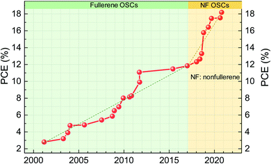 | ||
| Fig. 1 Power conversion efficiency evolution of organic solar cells (data extracted from the NREL Best Research-Cell Efficiency Chart).31 The dashed line is a guide for the eye to show the approximate slop of efficiency increase. | ||
In 2015, Zhan's group reported an efficient nonfullerene acceptor (NFA) of ITIC, which achieved PCE approaching that of fullerene devices.14 This is a milestone for OSC research and changes the conventional wisdom that fullerenes are the necessary electron acceptor in the efficient BHJ structure. It opens up a new pathway to optimize the efficiency and stability of OSCs. Due to the designing flexibility of NFA structures, optical and electrical properties can be readily tuned, including absorption spectra, energy levels, the film morphology and crystallinity for efficient charge separation and high charge carrier mobility.4,12,15–20 The high absorption coefficient and broad absorption of NFAs yield high short-circuit current (JSC). Negligible driving force for charge transfer between donors and NFAs yields low voltage loss and high output VOC. With the endeavors of the community on materials design and device optimization, PCEs of nonfullerene OSCs have rapidly reached over 18% (Fig. 1).21–29 Recently, tandem solar cells with PCEs over 19% have been reported by reducing thermalization loss in tandem configurations.30
Apart from high efficiency, operational stability is critical to be considered for the industrialization of OSCs.32,33 There are several factors that influence operational stability of devices under illumination: (i) chemical stability of materials used in devices under illumination;34 (ii) the morphology and crystalline stability of the BHJ active layer under illumination since the BHJ active layers consist of binary or ternary materials;35 (iii) interface stability between the active layer and the interfacial layer/charge-transporting layer. The first two aspects have been discussed in recent reviews.33–40 In this perspective, we will focus on the third aspect of interface stability based on research in the past four years.
In early 2018, we first reported that detrimental chemical reactions occurred between a low-work function interfacial layer of polyethylenimine (PEI) and ITIC. It significantly reduced electron extraction at the interface and therefore photovoltaic performance,41 which is completely different from what was observed in fullerene OSCs where PEI can work very efficiently for electron extraction.42 This suggests that the required interfacial layers are different for efficient fullerene and nonfullerene OSCs. Interfacial layers are key components for the device performance and long-term stability of OSCs. Since then, the interface stability study has attracted great attention from the research community, including understanding the reaction mechanism, designing new interfacial layers, and proposing new methods to suppress the reactions to improve the device performance and operational stability. In the past four years, we have gained an understanding of the interface interaction and developed methods of manipulating the interactions.41–51
In this perspective, first, we will describe and discuss the phenomena and mechanism of the interactions between the nonfullerene active layer and interfacial layer from the view of the chemical structure and electronic properties; methods to test and analyze the chemical stability of NFAs will be discussed. Second, strategies of designing a chemically stable nonfullerene active layer or electron transporting layer and modifying the interfacial layer to suppress chemical reactions will be discussed. Third, strategies of developing photochemically stable electron transporting layers and surface modification on interfacial layers to suppress the photochemical reaction will be discussed. Finally, we will summarize the perspective and provide outlooks on the interface stability of nonfullerene OSCs.
2. Understanding of the interface stability issues of NFAs
The first highly impactful NFA (ITIC, chemical structure shown in Fig. 2a) was discovered in 2015 by Zhan et al.14 It delivered a power conversion efficiency of 6.8% when PTB7-Th was the electron donor in the BHJ active layer. At that time, the PCE was lower than the highest one based on the fullerene-containing BHJ active layer (9–10%). In the next year of 2016, the PCEs of ITIC-based solar cells were rapidly enhanced to 11% when the electron donor was changed from the PTB7-Th to PBDB-T polymer developed by Hou et al.52 The efficiency surpassed those of fullerene solar cells (Fig. 1). Then, the community mostly switched to study the nonfullerence- rather than fullerene-containing OSCs. The efficiency was further enhanced to 13% with fluorine atoms introduced on NFAs and polymer electron donors.53 Later, another milestone of this field is the development of another NFA, Y6.54 The highest PCE of single-junction solar cells based on Y6 and its derivatives now reaches over 18%.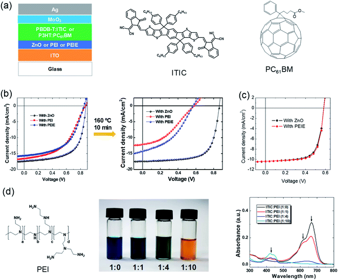 | ||
| Fig. 2 Phenomena of interfacial instability. (a) Device structure of typical inverted organic solar cells. The active layer is sandwiched between two electrodes. Two interfacial layers are included between the active layer and the electrodes. Chemical structures of a representative fullerene acceptor (PCBM) and representative NFA (ITIC); (b) J–V characteristics of the nonfullerene OSCs with ZnO, PEI, and PEIE as the interfacial layers, respectively, before and after thermal annealing at 160 °C for 10 min; (c) J–V characteristics of fullerene-based OSCs with the two interfacial layers; (d) chemical structure of PEI. Images and absorbance spectra of PEI:ITIC mixed solutions with different ratios. Reproduced from ref. 41 with permission from the Royal Society of Chemistry, copyright [2018]. | ||
2.1 Phenomenon of interfacial instability
Fig. 2a shows a typical device structure of inverted organic solar cells. It consists of active layers, two electrodes and two interfacial layers. The BHJ active layer plays an important role in light harvesting and generation of charge carriers. The two electrodes are used to collect electrons and holes, respectively. One of the electrodes must be transparent for light passing through and reaching the active layer. The two interfacial layers are also critical components of the OSCs to form an ohmic contact between the electrodes and active layer for efficient electron and hole collection, respectively.During the era of fullerene acceptor-based OSCs (1995–2016), interfacial layers have been systematically studied and developed for enhancing device efficiency. In the inverted device structure, ZnO is a widely used electron-transporting layer on top of the transparent electrode of indium tin oxide. ZnO has the advantages of easy fabrication and high collection efficiency. It can be easily fabricated by coating the solution precursor (typically consisting of zinc acetate dehydrate and ethanolamine dissolved in 2-methoxyethanol) followed by a gentle thermal annealing at around 130 °C.55 However, ZnO also has limited mechanical flexibility and a photocatalytic effect to induce the decomposition of active layers.43,46
In addition to ZnO, another series of electron-collecting interfacial layers for fullerene OSCs are amine-containing polymers or small molecules, such as polyethylenimine (PEI) or ethoxylated PEI (PEIE), poly[(9,9-bis(3′-(N,N-dimethylamino) propyl)-2,7-fluorene)-alt-2,7-(9,9-dioctylflu-orene)] (PFN), and amine-functionalized perylene diimide (PDIN). These materials can significantly reduce the work function of ITO. He et al. reported a PCE of 9.2% for organic solar cells by employing PFN as a modification layer on ITO with PTB7-Th:PCBM as the active layer.56 PEI/PEIE is another widely used material for efficient electron collection in fullerene active layer-based OSCs. PEI or PEIE can universally and significantly reduce the work function of various conductors, such as metals, metal oxides, graphene, and conducting polymers. It can transform the widely used hole-transporting layer PEDOT:PSS (poly(3,4-ethylenedioxythiophene):poly(styrenesulfonate)) into an electron-transporting layer.42 It is also widely used in other solution-processed devices (perovskite or II–VI quantum-dot solar cells, light-emitting diodes, and transistors).57–62
Then, it is straightforward to apply these developed interfacial materials into these emerging nonfullerene active layers. But some unexpected issues occurred. As shown in Fig. 2b, devices with PEI/PEIE interfacial layers show poorer performance than those with a ZnO layer. An “S” shape is observed in the current density–voltage (J–V) characteristics of the devices with PEI/PEIE interfacial layers. This suggests that there are issues of charge collection at the interfaces. Since charge extraction is not allowed, charge accumulation at the electrode occurs. Due to this, a voltage drop occurs, leading to a typical flex “S”-shape in the J–V characteristics.63,64 The issues become more severe after a thermal annealing at 160 °C for 10 min (Fig. 2b). The ZnO interlayer works efficiently in nonfullerene OSCs, while PEI/PEIE does not. The results are different when ZnO and PEI/PEIE are applied in fullerene active layer-based OSCs, where the two interfacial layers deliver nearly identical J–V characteristics (Fig. 2c).
It is puzzling to understand the phenomenon that PEI/PEIE cannot work efficiently as an interfacial layer for emerging nonfullerene active layers. With a lot of effort, it was found that there are chemical reactions between PEI/PEIE and NFAs. Fig. 2d shows the images and absorbance spectra of the mixtures of PEI and ITIC in different ratios. As the mixing ratio of PEI increases, the color of the solution changes from dark blue to orange. Absorbance spectra in the region of 600–700 nm decrease and disappear as the content of PEI increases in the mixed solution. The reaction changes the electronic structure of the ITIC, and also destroys the PEI. The function of PEI is also destroyed, resulting in the poor electron collection of the PEI.
2.2 Chemical structure of efficient NFAs
PEI/PEIE works efficiently as an interfacial layer in fullerene solar cells. The electrical conductivity of PEI/PEIE can significantly increase due to the doping effect of PEI/PEIE and PCBM.65 However, for NFAs, there are detrimental chemical reactions between PEI/PEIE and the NFA of ITIC. PCBM and ITIC react with PEI/PEIE in different ways. The difference has to do with their different chemical structures.Inside the ITIC, the donor moiety is IDT and the acceptor moiety is INCN. The IDT shows an absorption band at 320–420 nm. The INCN shows an absorption band lower than 400 nm. Once the IDT and INCN are linked via a conjugated C![[double bond, length as m-dash]](https://www.rsc.org/images/entities/char_e001.gif) C bond, the absorption band is extended to 550–750 nm (Fig. 3a). The intramolecular charge transfer (ICT) from IDT to INCN significantly extends the light absorption, which is the main source for light harvesting and light-to-electricity conversion. Fig. 3b shows the chemical structure of some representative efficient NFAs, including the milestone molecules of ITIC and Y6. These materials are in an acceptor–donor–acceptor (A–D–A) structure. Inside these molecules, there is an ICT between the donor moiety and acceptor moiety. The ICT states deliver a narrow band gap and extend the absorption of the materials.
C bond, the absorption band is extended to 550–750 nm (Fig. 3a). The intramolecular charge transfer (ICT) from IDT to INCN significantly extends the light absorption, which is the main source for light harvesting and light-to-electricity conversion. Fig. 3b shows the chemical structure of some representative efficient NFAs, including the milestone molecules of ITIC and Y6. These materials are in an acceptor–donor–acceptor (A–D–A) structure. Inside these molecules, there is an ICT between the donor moiety and acceptor moiety. The ICT states deliver a narrow band gap and extend the absorption of the materials.
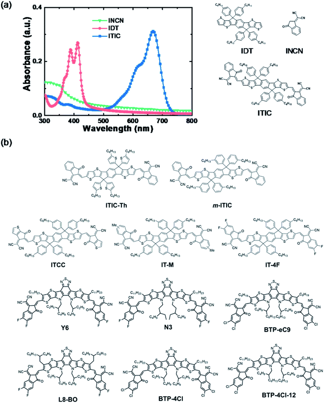 | ||
| Fig. 3 (a) Absorbance and chemical structures of a representative NFA of ITIC and its fragments; (b) chemical structures of recently developed high-performance NFAs. | ||
2.3 Chemical reaction between interfacial layers and NFAs
The electronic structures of NFAs rely on the ICT states of the A–D–A structure. For fullerenes, there are no such electron donor or acceptor moieties, and thus no such ICT states. Chemical reactivities of these two types of electron acceptors are different. Fullerene acceptors have good chemical compatibility and stability with PEI/PEIE, and PEI/PEIE as the interfacial layer can deliver high performance in fullerene OSCs. In nonfullerene OSCs, the poor device performance and absorption change of ITIC solution suggest the detrimental chemical reaction between the ITIC and PEI/PEIE.The reaction mechanism of PEIE with NFAs was studied via mass spectroscopy and nuclear magnetic resonance (NMR). Ethanolamine was adopted as the model compound to simplify the analysis because the structure of PEIE polymer is complex. Fig. 4a shows that the intensity of 1H NMR at the C![[double bond, length as m-dash]](https://www.rsc.org/images/entities/char_e001.gif) C bridge decreases as the concentration of ethanolamine increases. Mass spectroscopy suggests that ethanolamine is chemically added onto the C
C bridge decreases as the concentration of ethanolamine increases. Mass spectroscopy suggests that ethanolamine is chemically added onto the C![[double bond, length as m-dash]](https://www.rsc.org/images/entities/char_e001.gif) C bridge and the acceptor moiety falls off from the C
C bridge and the acceptor moiety falls off from the C![[double bond, length as m-dash]](https://www.rsc.org/images/entities/char_e001.gif) C bridge (Fig. 4b). The amine group reacts as a nucleophile with the C
C bridge (Fig. 4b). The amine group reacts as a nucleophile with the C![[double bond, length as m-dash]](https://www.rsc.org/images/entities/char_e001.gif) C linker in NFAs through an addition reaction, and eventually destroys the double bond and the large conjugated structure of the molecule, resulting in the loss of ICT states (Fig. 4c).
C linker in NFAs through an addition reaction, and eventually destroys the double bond and the large conjugated structure of the molecule, resulting in the loss of ICT states (Fig. 4c).
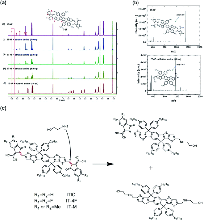 | ||
| Fig. 4 (a) In situ 1H NMR spectra of pristine IT-4F and IT-4F after adding different equivalents of ethanolamine; (b) the mass spectra of pristine IT-4F and IT-4F after adding 8.0 eq. ethanol amine, respectively. The detection was operated in negative ion mode; (c) reaction scheme of NFA of ITIC and ethanolamine. Reproduced from ref. 43 with permission from the Nature Publishing Group, copyright [2020]. | ||
Moreover, the chemical stability of NFAs in an inorganic acid-base environment was also studied.44 Under base conditions by adding NaOH into the ITIC solution, OH− anions act as nucleophiles to attack the C![[double bond, length as m-dash]](https://www.rsc.org/images/entities/char_e001.gif) C linker of ITIC and generated ITIC-OH. The solution color changed from blue to orange (Fig. 5a), which is similar to that of ITIC mixed with PEIE in Fig. 2d. The absorbance of the solution also significantly changed after adding NaOH. The efficiency of the devices with the ITIC-based active layers decreased from 9.68% to 0.24% after adding NaOH. In contrast, ITIC was chemically stable under acid conditions. After adding acetic acid into the ITIC solution, the solution color and absorption did not change compared with those of the pristine ITIC solution. Furthermore, adding the acid can convert the base-induced product back to ITIC, including the solution color, absorption and device performance (Fig. 5a–d). Fig. 5e shows the reaction scheme of the ITIC under base and acid conditions. When NaOH was added into the ITIC solution, the product of ITIC–OH formed via the addition reaction. When acetic acid was added into the ITIC–OH solution, the ITIC–OH changed back to ITIC. The conversion between ITIC and ITIC–OH is reversible under basic and acidic conditions.
C linker of ITIC and generated ITIC-OH. The solution color changed from blue to orange (Fig. 5a), which is similar to that of ITIC mixed with PEIE in Fig. 2d. The absorbance of the solution also significantly changed after adding NaOH. The efficiency of the devices with the ITIC-based active layers decreased from 9.68% to 0.24% after adding NaOH. In contrast, ITIC was chemically stable under acid conditions. After adding acetic acid into the ITIC solution, the solution color and absorption did not change compared with those of the pristine ITIC solution. Furthermore, adding the acid can convert the base-induced product back to ITIC, including the solution color, absorption and device performance (Fig. 5a–d). Fig. 5e shows the reaction scheme of the ITIC under base and acid conditions. When NaOH was added into the ITIC solution, the product of ITIC–OH formed via the addition reaction. When acetic acid was added into the ITIC–OH solution, the ITIC–OH changed back to ITIC. The conversion between ITIC and ITIC–OH is reversible under basic and acidic conditions.
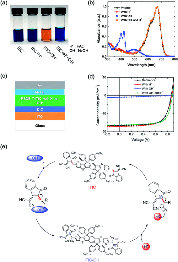 | ||
| Fig. 5 (a) Image, and (b) the absorbance of four different ITIC solutions: pristine, and with the addition of H+, OH−, and both OH− and H+; (c) device structure; (d) J–V characteristics of devices with active layers having acid or base additives; (e) scheme of the reversible reaction of ITIC under acidic and basic conditions. Reproduced from ref. 44 with permission from the American Chemical Society, copyright [2019]. | ||
The chemical reactivity of NFAs with a base is related to their chemical structures. Hu et al. compared the chemical reactivity of NFAs with that of different terminal groups of the ITIC family: ITIC, IT-M, and IT-4F.45 IT-M and IT-4F are the methyl group and fluorine atoms attached on ITIC molecules as the terminal groups, respectively. NMR and optical absorption were used to monitor their chemical kinetics with the model compound of ethanolamine. As shown in Fig. 6a, IT-M and ITIC have similar reactivities, but IT-4F with terminal fluorine substitution shows much higher chemical reactivity than ITIC and IT-M. Fluorine is highly electronegative and pulls the electron cloud towards the acceptor moiety, increasing the chemical reactivity of the C![[double bond, length as m-dash]](https://www.rsc.org/images/entities/char_e001.gif) C bridge between the donor and acceptor moieties.
C bridge between the donor and acceptor moieties.
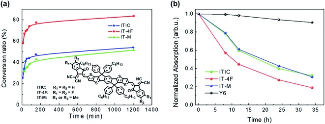 | ||
Fig. 6 (a) Plots of the NFA conversion ratio calculated from 1H NMR spectra as a function of reaction time with an ethanolamine![[thin space (1/6-em)]](https://www.rsc.org/images/entities/char_2009.gif) : :![[thin space (1/6-em)]](https://www.rsc.org/images/entities/char_2009.gif) acceptor ratio of 4 acceptor ratio of 4![[thin space (1/6-em)]](https://www.rsc.org/images/entities/char_2009.gif) : :![[thin space (1/6-em)]](https://www.rsc.org/images/entities/char_2009.gif) 1 at room temperature; (b) plots of the normalized absorption intensity of the main peak as a function of reaction time. Reproduced from ref. 45 with permission from the American Chemical Society, copyright [2020]. 1 at room temperature; (b) plots of the normalized absorption intensity of the main peak as a function of reaction time. Reproduced from ref. 45 with permission from the American Chemical Society, copyright [2020]. | ||
In addition to acceptor moieties, chemical reactivity is also influenced by the donor moieties of NFAs. Y6 has the same acceptor moieties as IT-4F but different donor moieties. Although the terminal group is substituted with fluorine, Y6 shows much better chemical stability with amine than IT-4F, ITIC, and IT-M (Fig. 6b). The good chemical stability of Y6 originates from its chemical structure, which is different from the ITIC family. The molecular structure of Y6 is in the so-called A–D–A′–D–A structure, while ITIC is in the A-D-A structure. The electron withdrawing unit inside the donor moieties can improve the chemical stability of NFAs. On the other hand, the long alkyl chain of –C11H23 on both sides of the Y6 donor moieties greatly increases the steric hindrance of the C![[double bond, length as m-dash]](https://www.rsc.org/images/entities/char_e001.gif) C linkage between the donor moieties and the acceptor moieties, thus hindering the attack of the amine group and further increasing the chemical stability.
C linkage between the donor moieties and the acceptor moieties, thus hindering the attack of the amine group and further increasing the chemical stability.
2.4 Photochemical reaction between interfacial layers and NFAs
In the previous section, interfacial chemical stability and reactivity between the nonfullerene active layer and the interfacial layer have been discussed. In addition, OSCs operate under light illumination. Photostability is also highly important for OSCs.In 2019, our group first reported that inverted OSCs with a ZnO electron-transporting layer shows poor operational stability under 100 mW cm−2 AM1.5 G illumination.46 After 24 h illumination, the PCE of the OSCs (with PM6:IT-4F active layer) decreased from 13.0% (VOC = 0.84 V, JSC = 20.7 mA cm−2, and FF = 0.75) to 5.1% (VOC = 0.66 V, JSC = 17.0 mA cm−2, and FF = 0.45) (Fig. 7a–c). Under 365 nm UV illumination, the IT-4F on glass substrate was stable, but decomposed rapidly when deposited on the ZnO surface under UV illumination. The photocatalytic effect of ZnO films induced the decomposition of the NFA of IT-4F. The IT-4F was broken at the C![[double bond, length as m-dash]](https://www.rsc.org/images/entities/char_e001.gif) C bridge and turned into fragments of donor and acceptor moieties as observed characterization by mass spectroscopy. The original ICT between the IDTT and the EG-2F moieties in IT-4F was destroyed and thus the color disappeared (5 nm IT-4F film) (Fig. 7d and e).
C bridge and turned into fragments of donor and acceptor moieties as observed characterization by mass spectroscopy. The original ICT between the IDTT and the EG-2F moieties in IT-4F was destroyed and thus the color disappeared (5 nm IT-4F film) (Fig. 7d and e).
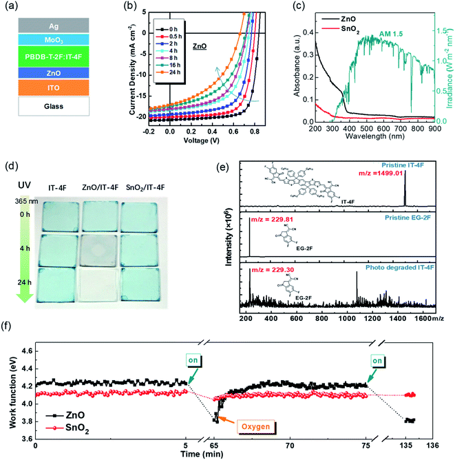 | ||
| Fig. 7 (a) Device structure; (b) evolution of the J–V characteristics of the devices under 100 mW cm−2 AM1.5 illumination; (c) absorbance spectra of ZnO and SnO2 films and the AM1.5 G solar irradiation spectrum; (d) images of IT-4F thin films (5 nm) on glass, glass/ZnO, and glass/SnO2 substrates under continuous UV illumination (365 nm, 5 mW cm−2) for different times; (e) mass spectra of pristine NFA IT-4F, pristine acceptor moiety EG-2F, and photo-degraded IT-4F, respectively; (f) work function evolution of ZnO and SnO2 films after 100 mW cm−2 AM1.5 G illumination and air exposure. Reproduced from ref. 46 with permission from the Royal Society of Chemistry, copyright [2019]. | ||
ZnO is also a widely used material in the field of photocatalysis.66–68 For solution-processed ZnO films, the Zn atoms and O atoms are usually not in 1![[thin space (1/6-em)]](https://www.rsc.org/images/entities/char_2009.gif) :
:![[thin space (1/6-em)]](https://www.rsc.org/images/entities/char_2009.gif) 1 stoichiometry. There generally exists defects including oxygen vacancies (VO+) and zinc interstitial atoms (Zni+). These are all donor-type defects with low formation energy and prone to losing electrons.69–72 Oxygen is usually adsorbed at these defects of ZnO. Meanwhile, ZnO has a band gap of 3.3 eV, which can absorb UV light below 380 nm to generate free charge carriers.73 The free radical excites the adsorbed water or hydroxide spices to form hydroxyl radicals (·OH). The hydroxyl radicals react with IT-4F and cause the decomposition of IT-4F.74,75 The photocatalytic effect of ZnO inducing the decomposition of IT-4F under UV illumination is similar to that of ZnO inducing the decomposition of methylene blue.66 Since approximately 2 mW cm−2 UV light below 380 nm is contained in standard the 100 mW cm−2 AM1.5 G solar spectrum, the decomposition also occurs under solar irradiation.
1 stoichiometry. There generally exists defects including oxygen vacancies (VO+) and zinc interstitial atoms (Zni+). These are all donor-type defects with low formation energy and prone to losing electrons.69–72 Oxygen is usually adsorbed at these defects of ZnO. Meanwhile, ZnO has a band gap of 3.3 eV, which can absorb UV light below 380 nm to generate free charge carriers.73 The free radical excites the adsorbed water or hydroxide spices to form hydroxyl radicals (·OH). The hydroxyl radicals react with IT-4F and cause the decomposition of IT-4F.74,75 The photocatalytic effect of ZnO inducing the decomposition of IT-4F under UV illumination is similar to that of ZnO inducing the decomposition of methylene blue.66 Since approximately 2 mW cm−2 UV light below 380 nm is contained in standard the 100 mW cm−2 AM1.5 G solar spectrum, the decomposition also occurs under solar irradiation.
We reported that the work function of ZnO could decrease substantially from 4.2 to 3.8 eV under UV light and it could recover to the original value of 4.2 eV after air exposure (Fig. 7f).46 The decrease of the work function is due to the oxygen desorption on the ZnO surface after UV irradiation, and the recovery of the work function is related to the oxygen re-adsorption on the ZnO surface. The reversible change of the work function associated with the oxygen desorption/adsorption suggests the existence of defects (VO+ and Zni+) on the surface of ZnO. After being excited by UV light (hv > Eg), ZnO absorbs photons and electron–hole pairs were generated. The holes captured electrons from the adsorbed oxygen and then quenched, resulting in neutral oxygen desorption from the surface. Then the work function was reduced and free electrons were left in the ZnO conduction band. It is generally believed that the free radical excites the adsorbed water or hydroxide spices to form hydroxyl radicals (˙OH).74,75 The hydroxyl radicals could break the double bond at the junction of the A–D–A structure of the NFAs. Hu et al.43 used 1,4-benzoquinone (Qu) as an electron quencher to study its effect on the photo-decomposition of Y6. The results revealed that adding Qu to ZnO precursor solution could inhibit the photo-decomposition of Y6 catalyzed by ZnO. Electron spin resonance (ESR) spectroscopy characterization showed that the defect peaks of Qu-modified ZnO significantly decreased. The radicals play an essential role in breaking the C![[double bond, length as m-dash]](https://www.rsc.org/images/entities/char_e001.gif) C bond between the donor and the acceptor moieties.
C bond between the donor and the acceptor moieties.
Later, Son et al.74 reported a similar photocatalytic reaction between the NFA and ZnO that accelerated the decomposition of NFA, which resulted in a rapid efficiency degradation of PBDB-T-2F:ITIC-based devices. The efficiency decreased to one-fifth of their initial efficiency after 1000 h light exposure, while the device based on the PTB7:PCBM active layer remained above 60% after over 4000 h illumination. The authors identified the complicated products after the photochemical reaction of ITIC and ZnO via 1H NMR and mass spectroscopy. They speculated that hydroxyl radicals (˙OH) were generated through the reaction of photogenerated electrons with adsorbed H2O in the ZnO. An addition reaction occurs between the vinyl double bond in ITIC and the hydroxyl radical. ITIC free radical intermediates could further decompose into small fragments. In the meantime, the ITIC radical could act as an electrophile, then attacking the vinyl double bond of another ITIC molecule and forming a dimerized ITIC. The decomposition of the vinyl double bond in ITIC destroyed its conjugated structure, resulting in poor electron transport at the ZnO/active layer interface (Fig. 8a). As a result, PBDB-T-2F:ITIC based solar cells exhibited significant charge accumulation and recombination at the ZnO interface, resulting in a rapid decrease of FF, VOC and PCE values.
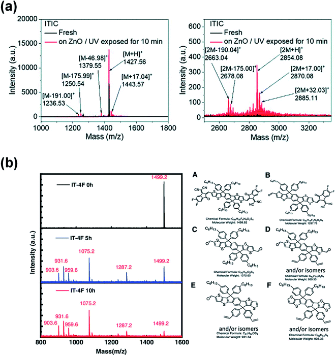 | ||
| Fig. 8 (a) Mass spectra of aged ITIC on the ZnO surface. Reproduced from ref. 74 with permission from the Royal Society of Chemistry, copyright [2019]. (b) Mass spectra of the pristine IT-4F and the products of the aged IT-4F on the DMSO-ZnO surface; reproduced from ref. 75 with permission from the Wiley, copyright [2020]. | ||
More recently, Ma et al.75 reported that not only can UV light trigger a photocatalytic reaction between ZnO and NFAs, but visible light can also cause the photocatalytic degradation of PBDB-T-2F:IT-4F solar cells by ZnO. The photobleaching rate of the IT-4F film on the ZnO surface and device performance degradation are directly related to the absorption of visible light by the ZnO layers. Light absorption of ZnO is the premise for the photo-decomposition of acceptor molecules on it. Products of the IT-4F/ZnO film after the photochemical reaction are identified via mass spectroscopy. The main products are the fragments of the donor moiety with the aldehyde group as the terminal group due to the breakage at the C![[double bond, length as m-dash]](https://www.rsc.org/images/entities/char_e001.gif) C bond of the IT-4F (Fig. 8b).
C bond of the IT-4F (Fig. 8b).
Based on the above studies, it is generally presumed that the photoinduced decomposition position in the A–D–A structure of NFAs is the C![[double bond, length as m-dash]](https://www.rsc.org/images/entities/char_e001.gif) C vinyl linker. However, there also are different opinions. Recently, Li et al.76 believed that the photoisomerization of the exocyclic vinyl linker could act as a surrogate toward their subsequent photooxidation in the A–D–A structure of NFAs by studying the photostability of representative examples including fused (IT-4F), semi-fused (HF-PCIC), and non-fused-cores (PTIC) (Fig. 9a). Perepichka et al.77 reported that the photodegradation of NFAs in the A–D–A structure involved the dicyanomethylene moiety, while the vinyl linker was not the intermediate reaction center. The photoproducts of IT-4F were proved to be isomers formed by a 6-e electrocyclic reaction between the dicyanomethylene unit and the thiophene ring, followed by a 1,5-sigmatropic hydride shift rather than the photooxidation of the vinyl linker (Fig. 9b). At this stage, according to the literature reports and our results, there are three possible reaction routes: (1) the additional reaction of the C
C vinyl linker. However, there also are different opinions. Recently, Li et al.76 believed that the photoisomerization of the exocyclic vinyl linker could act as a surrogate toward their subsequent photooxidation in the A–D–A structure of NFAs by studying the photostability of representative examples including fused (IT-4F), semi-fused (HF-PCIC), and non-fused-cores (PTIC) (Fig. 9a). Perepichka et al.77 reported that the photodegradation of NFAs in the A–D–A structure involved the dicyanomethylene moiety, while the vinyl linker was not the intermediate reaction center. The photoproducts of IT-4F were proved to be isomers formed by a 6-e electrocyclic reaction between the dicyanomethylene unit and the thiophene ring, followed by a 1,5-sigmatropic hydride shift rather than the photooxidation of the vinyl linker (Fig. 9b). At this stage, according to the literature reports and our results, there are three possible reaction routes: (1) the additional reaction of the C![[double bond, length as m-dash]](https://www.rsc.org/images/entities/char_e001.gif) C vinyl linker; (2) the photoisomerization and photooxidation of the C
C vinyl linker; (2) the photoisomerization and photooxidation of the C![[double bond, length as m-dash]](https://www.rsc.org/images/entities/char_e001.gif) C vinyl linker; (3) the electrocyclic reaction between the dicyanomethylene unit and the thiophene ring. The reaction process may vary depending on the chemical structures of the NFAs and also reaction conditions, including oxygen, light exposure, heat etc. More studies and reports further on the reactions of NFAs will allow us to understand more clearly the degradation mechanisms.
C vinyl linker; (3) the electrocyclic reaction between the dicyanomethylene unit and the thiophene ring. The reaction process may vary depending on the chemical structures of the NFAs and also reaction conditions, including oxygen, light exposure, heat etc. More studies and reports further on the reactions of NFAs will allow us to understand more clearly the degradation mechanisms.
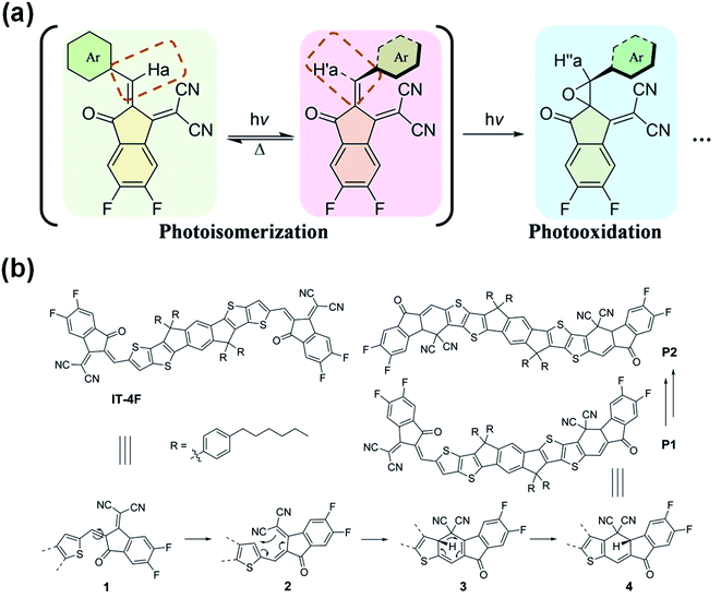 | ||
| Fig. 9 (a) Photochemical reaction of NFAs; (b) mechanism of the photodegradation of IT-4F; reproduced from ref. 76 with permission from the Nature Publishing Group, copyright [2021]. Reproduced from ref. 77 with permission from the Wiley, copyright [2021]. | ||
3. Strategies to suppress interfacial chemical reactions
As discussed in Section 2, the C![[double bond, length as m-dash]](https://www.rsc.org/images/entities/char_e001.gif) C vinyl linkage between the donor and acceptor moieties is the weak position of those high-performance NFAs. It can react with organic and also inorganic bases, such as PEI/PEIE, NaOH etc. The C
C vinyl linkage between the donor and acceptor moieties is the weak position of those high-performance NFAs. It can react with organic and also inorganic bases, such as PEI/PEIE, NaOH etc. The C![[double bond, length as m-dash]](https://www.rsc.org/images/entities/char_e001.gif) C vinyl group is also prone to breaking under illumination by ZnO via the photocatalytic effect.
C vinyl group is also prone to breaking under illumination by ZnO via the photocatalytic effect.
To suppress the chemical reaction between the interfacial layer and the NFA (note: strategy of photochemical reaction will be discussed in the next section), one is to modify the chemical structure of NFAs to suppress the chemical reactivity of the NFAs themselves; the second is to modify the interfacial layer material to reduce its chemical reactivity and therefore inhibit the interface chemical reaction; the third is to develop other chemically stable ETL materials (ETLs) to suppress the chemical reaction between the amine groups of ETLs and the NFAs.
3.1 Improving the intrinsic chemical stability of NFAs
Considering that the amine group would attack the C![[double bond, length as m-dash]](https://www.rsc.org/images/entities/char_e001.gif) C linker of the A–D–A structure of NFAs through an addition reaction as a nucleophile, Li et al.78 reported a ring-locked C
C linker of the A–D–A structure of NFAs through an addition reaction as a nucleophile, Li et al.78 reported a ring-locked C![[double bond, length as m-dash]](https://www.rsc.org/images/entities/char_e001.gif) C linker in the molecular structure to replace the general C
C linker in the molecular structure to replace the general C![[double bond, length as m-dash]](https://www.rsc.org/images/entities/char_e001.gif) C vinyl group between the donor and acceptor moieties (Fig. 10a). The ring-locked C
C vinyl group between the donor and acceptor moieties (Fig. 10a). The ring-locked C![[double bond, length as m-dash]](https://www.rsc.org/images/entities/char_e001.gif) C linker maintains the conjugated structure. In the meantime, it increases the steric hindrance of nucleophilic attack and forms intramolecular C–H⋯O interactions. Thus, the intrinsic chemical stability of A–D–A type NFAs is significantly enhanced. IDTT-CR based on 2-(1,1-dicyanomethylene)rhodamine with a ring-locked structure was successfully synthesized (Fig. 10b). As shown in Fig. 10c, after adding ethanolamine, the ICT absorption band of the IDTT-CR was significantly enhanced and remained above 85% after 19 h, while the ICT absorption band of compounds without a ring-locked strategy was only 30%. Fig. 10d shows that ring-locked IDTT-CR demonstrated great photostability. These results revealed that NFAs of IDTT-CR with a ring-locked structure showed a greatly improved chemical and photochemical stability.
C linker maintains the conjugated structure. In the meantime, it increases the steric hindrance of nucleophilic attack and forms intramolecular C–H⋯O interactions. Thus, the intrinsic chemical stability of A–D–A type NFAs is significantly enhanced. IDTT-CR based on 2-(1,1-dicyanomethylene)rhodamine with a ring-locked structure was successfully synthesized (Fig. 10b). As shown in Fig. 10c, after adding ethanolamine, the ICT absorption band of the IDTT-CR was significantly enhanced and remained above 85% after 19 h, while the ICT absorption band of compounds without a ring-locked strategy was only 30%. Fig. 10d shows that ring-locked IDTT-CR demonstrated great photostability. These results revealed that NFAs of IDTT-CR with a ring-locked structure showed a greatly improved chemical and photochemical stability.
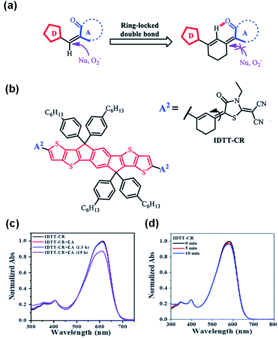 | ||
Fig. 10 (a) Schematic of the ring-locked strategy to protect the C![[double bond, length as m-dash]](https://www.rsc.org/images/entities/char_e001.gif) C from the attack of nucleophiles or photooxidation; (b) chemical structure of IDTT-CR; normalized UV-vis absorption spectra of (c) IDTT-CR before and after adding ethanolamine in THF C from the attack of nucleophiles or photooxidation; (b) chemical structure of IDTT-CR; normalized UV-vis absorption spectra of (c) IDTT-CR before and after adding ethanolamine in THF![[thin space (1/6-em)]](https://www.rsc.org/images/entities/char_2009.gif) : :![[thin space (1/6-em)]](https://www.rsc.org/images/entities/char_2009.gif) H2O mixtures (96 H2O mixtures (96![[thin space (1/6-em)]](https://www.rsc.org/images/entities/char_2009.gif) : :![[thin space (1/6-em)]](https://www.rsc.org/images/entities/char_2009.gif) 4, v/v); (d) IDTT-CR in THF solutions in air under different irradiation times (100 mW cm−2). Reproduced from ref. 78 with permission from the Royal Society of Chemistry, copyright [2021]. 4, v/v); (d) IDTT-CR in THF solutions in air under different irradiation times (100 mW cm−2). Reproduced from ref. 78 with permission from the Royal Society of Chemistry, copyright [2021]. | ||
Zhu et al.79 reported a new stable NFA by removing the C![[double bond, length as m-dash]](https://www.rsc.org/images/entities/char_e001.gif) C vinyl linker in the general A–D–A structure. The new NFA is all-fused-ring, 2,2′-(7,7,15,15-tetrahexyl-7,15-dihydro-s-indaceno[1,2-b:5,6-b′]diindeno[1,2-d]thiophene-2,10(2H)-diylidene)dimalononitrile (ITYM) (Fig. 11a). The structure of ITYM shows a planar non-acyclic structure with strong π–π stacking. Fig. 11b and c show the absorption decays of ITYM and the control NFAs at the corresponding maximum absorptions under ethanolamine treatment and AM 1.5G illumination, respectively. In Fig. 11b, only a minor decay of <5% was observed for ITYM after 12 h. In Fig. 11c, ITYM exhibits a longer 50% decay time (100 min) than the control NFAs, 55 min for IDIC, <2 min for ITIC and IT-4F. ITYM exhibits extraordinary chemical and photochemical stability with very promising performance compared with the general C
C vinyl linker in the general A–D–A structure. The new NFA is all-fused-ring, 2,2′-(7,7,15,15-tetrahexyl-7,15-dihydro-s-indaceno[1,2-b:5,6-b′]diindeno[1,2-d]thiophene-2,10(2H)-diylidene)dimalononitrile (ITYM) (Fig. 11a). The structure of ITYM shows a planar non-acyclic structure with strong π–π stacking. Fig. 11b and c show the absorption decays of ITYM and the control NFAs at the corresponding maximum absorptions under ethanolamine treatment and AM 1.5G illumination, respectively. In Fig. 11b, only a minor decay of <5% was observed for ITYM after 12 h. In Fig. 11c, ITYM exhibits a longer 50% decay time (100 min) than the control NFAs, 55 min for IDIC, <2 min for ITIC and IT-4F. ITYM exhibits extraordinary chemical and photochemical stability with very promising performance compared with the general C![[double bond, length as m-dash]](https://www.rsc.org/images/entities/char_e001.gif) C vinyl linked INCN-type acceptors (Fig. 11b–d). The all-fused-ring structure opens a new avenue toward high-efficiency and high-stability organic solar cells.
C vinyl linked INCN-type acceptors (Fig. 11b–d). The all-fused-ring structure opens a new avenue toward high-efficiency and high-stability organic solar cells.
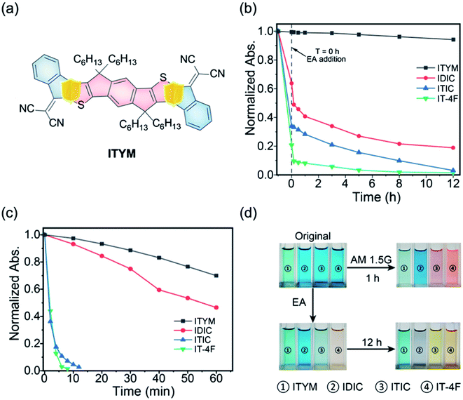 | ||
Fig. 11 (a) A new all-fused-ring NFA without the C![[double bond, length as m-dash]](https://www.rsc.org/images/entities/char_e001.gif) C linker (ITYM); (b) time-dependent absorption decays of ITYM and the control NFAs at the corresponding maximum absorptions upon the ethanolamine treatment; (c) and AM1.5 G illumination; (d) photos of ITYM and the control NFAs before and after the 12 h ethanolamine treatment and 1 h AM1.5 G illumination, respectively. Reproduced from ref. 79 with permission from the Chinese Chemistry Society, copyright [2021]. C linker (ITYM); (b) time-dependent absorption decays of ITYM and the control NFAs at the corresponding maximum absorptions upon the ethanolamine treatment; (c) and AM1.5 G illumination; (d) photos of ITYM and the control NFAs before and after the 12 h ethanolamine treatment and 1 h AM1.5 G illumination, respectively. Reproduced from ref. 79 with permission from the Chinese Chemistry Society, copyright [2021]. | ||
3.2 Modifying the interfacial layer to suppress its reaction with NFAs
Lone electron pairs in amines (such as PEI/PEIE) are the key elements to react with NFAs. Thus, deactivating the reactivity of the lone electron pairs in amines can effectively suppress the detrimental reaction between the PEI/PEIE and NFAs. Xiong et al.47 proposed a strategy of protonating the amine group in PEIE to passivate the chemical interaction between the PEIE interfacial layer and nonfullerene active layer. When PEIE was treated with different polar solvents of isopropanol, ethanol, methanol, and water, the degree of protonation could be adjusted. X-ray photoelectron spectroscopy (XPS) showed that the content of protonated amine groups in the aqueous PEIE solution was higher than that in isopropanol solution. This is mainly because: (1) water has a higher dielectric constant than isopropanol which induces the protonation of PEI/PEIE; (2) CO2 is dissolved in water which produces acidic water and can protonate the PEI/PEIE. Fig. 12a shows the device structure of PCE-10:IEICO-4F based OSCs with a PEIE interfacial layer. As shown in Fig. 12b–d, when processing PEIE with isopropanol, ethanol, and methanol (denoted as i-PEIE, e-PEIE, and m-PETE, respectively), the J–V characteristics of the device showed an “S” shape. The device performance was poor when compared with that of the ZnO reference device with a PCE of 12.6%, VOC of 0.70 V, JSC of 26.5 mA cm−2, and FF of 0.67. The poor performance was due to the poor charge collection caused by the interface reaction between the active layer and cathode layer. However, when PEIE was treated as an aqueous solution (denoted as a-PEIE), the device showed high performance with a PCE of 13.2%, VOC of 0.70 V, JSC of 27.2 mA cm−2, and FF of 0.69 (Fig. 12e), even higher than that of the reference device with ZnO. These results showed that amine protonation inhibited the reaction between a-PEIE and IEICO-4F and yielded efficient electron collection at the interface.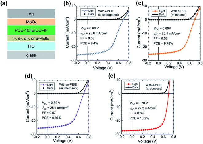 | ||
| Fig. 12 (a) Device structure of OSCs: i-, e-, m-, and a-PEIE denote PEIE processed from isopropyl alcohol, ethanol, methanol, and aqueous solutions, respectively; (b–e) J–V characteristics of the non-fullerene OSCs with different interfacial layers: (b) with i-PEIE; (c) with e-PEIE; (d) with m-PEIE; (e) with a-PEIE. Reproduced from ref. 47 with permission from the Wiley, copyright [2019]. | ||
In addition to the protonation of the amine group, chelation of amine groups with metal ions can also reduce the reactivity of the lone electron pairs and thus inhibit the reaction of amine groups and NFAs. Qin et al.43 proposed adding zinc acetate dihydrate into the PEI solution to realize the chelation of PEI with Zn2+. The zinc ion chelated PEI named PEI-Zn. Zn2+ has strong chelation activity with nitrogen atoms and amino groups. After chelation, the reaction between PEI and the IT-4F was inhibited. As shown in Fig. 13c, the mixed solution of IT-4F and Zn2+ chelated PEI showed similar color and absorption spectra to the pristine IT-4F solution, which proved that the chemical stability of PEI was improved after the Zn2+ chelation. This improvement in chemical stability was also evident in the device performance. As shown in Fig. 13a and b, the PBDB-T-2F:IT-4F based OSCs with PEI showed a serious “S” shape, where an interfacial chemical reaction occurred between PEI and IT-4F. As the proportion of zinc salt increased, the “S” shape of the devices gradually disappeared. When the mass ratio of zinc acetate dihydrate to PEI was 3![[thin space (1/6-em)]](https://www.rsc.org/images/entities/char_2009.gif) :
:![[thin space (1/6-em)]](https://www.rsc.org/images/entities/char_2009.gif) 1, the “S” shape of the device was weak. When the mass ratio of zinc acetate dihydrate to PEI was 5
1, the “S” shape of the device was weak. When the mass ratio of zinc acetate dihydrate to PEI was 5![[thin space (1/6-em)]](https://www.rsc.org/images/entities/char_2009.gif) :
:![[thin space (1/6-em)]](https://www.rsc.org/images/entities/char_2009.gif) 1, the OSCs showed high performance: VOC = 0.82 V, JSC =20.7 mA cm−2, FF = 0.72, and PCE = 12.4%, respectively. When the ratio of zinc salt to PEI was 15
1, the OSCs showed high performance: VOC = 0.82 V, JSC =20.7 mA cm−2, FF = 0.72, and PCE = 12.4%, respectively. When the ratio of zinc salt to PEI was 15![[thin space (1/6-em)]](https://www.rsc.org/images/entities/char_2009.gif) :
:![[thin space (1/6-em)]](https://www.rsc.org/images/entities/char_2009.gif) 1, the efficiency saturated: VOC = 0.84 V, JSC = 20.8 mA cm−2, FF = 0.76, and PCE = 13.3%, respectively. Further increasing the content of zinc salt would not increase the performance. Instead, the added zinc salt could not be chelated and precipitate which deteriorated the device performance. Fig. 13d and e show the XPS spectra of the PEI-Zn film with different ratios of zinc acetate dihydrate and PEI. As the ratio of zinc salt increased, the electron cloud density around the N element gradually decreased. The electron transfer on the N atom weakens the electronegativity of the amine group on the PEI, which also weakens the addition reaction between PEI and IT-4F. Hence, the reaction at the interface is inhibited and the device efficiency increases.
1, the efficiency saturated: VOC = 0.84 V, JSC = 20.8 mA cm−2, FF = 0.76, and PCE = 13.3%, respectively. Further increasing the content of zinc salt would not increase the performance. Instead, the added zinc salt could not be chelated and precipitate which deteriorated the device performance. Fig. 13d and e show the XPS spectra of the PEI-Zn film with different ratios of zinc acetate dihydrate and PEI. As the ratio of zinc salt increased, the electron cloud density around the N element gradually decreased. The electron transfer on the N atom weakens the electronegativity of the amine group on the PEI, which also weakens the addition reaction between PEI and IT-4F. Hence, the reaction at the interface is inhibited and the device efficiency increases.
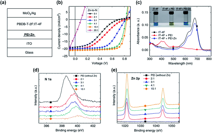 | ||
| Fig. 13 (a) Structure of OSC devices; (b) J–V characteristics of the devices with PEI-Zn ETL containing different Zn-to-N mole ratios; (c) absorption spectra of three solutions: IT-4F, IT-4F mixed with PEI, and IT-4F mixed with PEI-Zn solution. The inset shows the pictures of the three solutions; (d and e) XPS spectra of the PEI-Zn films containing different Zn-to-N ratios: e N 1s; f Zn 2p. Reproduced from ref. 43 with permission from the Nature Publishing Group, copyright [2020]. | ||
In addition to the zinc element, indium and tin elements in ITO can also chelate with the amine group in PEIE to reduce the chemical reaction activity of PEIE and inhibit the reaction between PEIE and nonfullerene active layers. The chelation between PEI and ITO occurs only at their interface. Thus, to deactivate the lone electron pairs of the entire PEI/PEIE films, they have to be extremely thin. Zeng et al.48 found that ultra-thin PEIE (1.2 nm, processed from isopropanol solvent) as an interfacial layer on top of ITO could deliver high performance in PM6:Y6-based OSCs with an efficiency of 15.3%. When the thickness of PEIE slightly increased to 5 nm, the PCE decreased rapidly to 7.5% (Fig. 14a–g). This is because the chelation of PEIE by ITO only occurred at the interface. The top surface of the thicker PEIE film (5 nm) contacting with PM6:Y6 layer cannot be chelated with the bottom ITO. There still exists the reaction between the PEIE and Y6 and thus the efficiency is significantly reduced. However, the ultrathin thickness of PEIE (processed from alcohol solvent) did not deliver performance as high as that of reference cells with the ZnO ETL for other NFAs, such as IT-4F. This is due to the stronger chemical reactivity of IT-4F with PEIE than Y6 as discussed in Fig. 6 in Section 2.3.
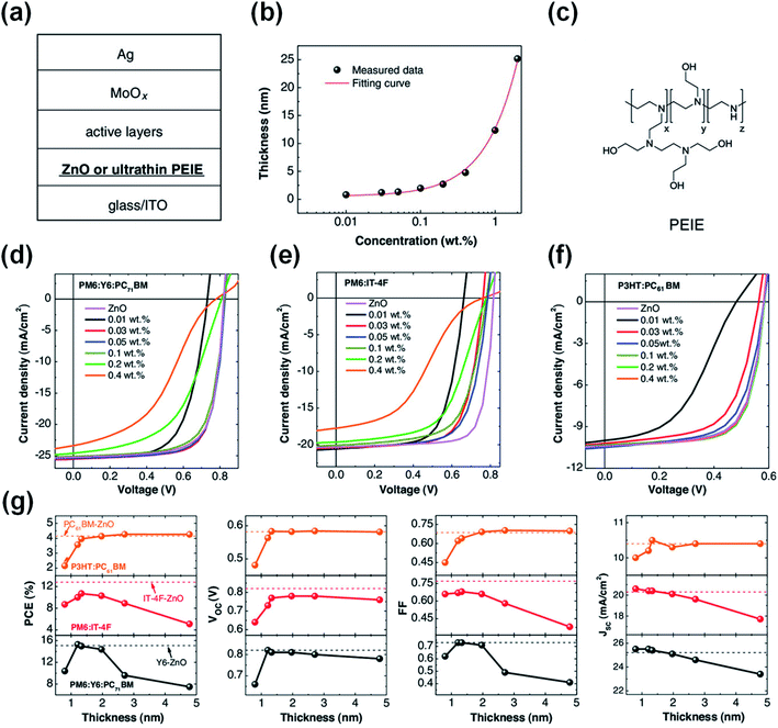 | ||
| Fig. 14 (a) Device structure of the OSCs; (b) thickness of PEIE layers as a function of processing concentration (isopropanol solvent); (c) chemical structure of PEIE; (d–f) J–V characteristics of OSCs with the device structure of ITO/PEIE or ZnO/active layers/MoOx/Ag. The active layers are: (d) PM6:Y6:PC71BM, (e) PM6:IT-4F, and (f) P3HT:PC61BM, respectively; (g) photovoltaic parameters of these cells as a function of PEIE thickness. The dashed lines represent the corresponding reference cells with ZnO as the electron-collecting layer. The black line: PM6:Y6:PC71BM-based cells, the red line: PM6:IT-4F-based cells, and the orange line: P3HT:PC61BM-based cells. Reproduced from ref. 48 with permission from the Wiley, copyright [2021]. | ||
In addition to metal ion chelation, small molecules were also used to modify PEIE to inhibit the reactions between PEIE and NFAs. Lim et al.80 inserted a molecule of ethanedithiol (EDT) at the PEIE/active layer interface for mitigating the undesirable reaction between amine-rich groups and electron-acceptor moieties in ITIC-M (Fig. 15a). Fig. 15b shows the J–V characteristics of the rigid OSC devices containing the ZnO, PEIE, and PEIE-EDT ETLs. The unmodified PEIE delivered a poor PCE of 9.60% with a VOC of 0.86 V, JSC of 18.92 mA cm−2, and FF of 0.59 due to the detrimental reaction. After the inclusion of the EDT molecule, the reaction between the lone pair on nitrogen atoms in PEIE with the electron-acceptor was suppressed. As a result, the performance of PEIE-EDT delivered a greatly improved PCE of 12.06% (VOC = 0.92 V, FF = 0.69, and JSC = 19.16 mA cm−2). Fig. 15c shows the photostability of OSCs devices under continuous light illumination. After 15 h, the PEIE-EDT device retained 80.83% of its initial PCE, whereas the ZnO device retained 19.33% of its initial PCE. EDT is an effective molecule to suppress the reaction between PEIE and the NFA for enhanced efficiency and stability. Zhao et al.81 used two other molecules of 1,8-dibromooctane (DBO) and 1,8-dichlorooctane (DCO) to graft PEIE as the ETL in nonfullerene OSCs (Fig. 15d). The quaternization of PEIE by the halogen is effective to suppress the reaction between PEIE and the NFAs. As a result, the OSCs based on PEIE-DBO with PTB7-Th:IEICO-4F, PM6:IT-4F, and PM6:Y6 as the active layers showed PCE values of 12.05%, 13.34% and 15.74%, respectively, which were much enhanced compared with those of the device with unmodified PEIE interfaces (Fig. 15e).
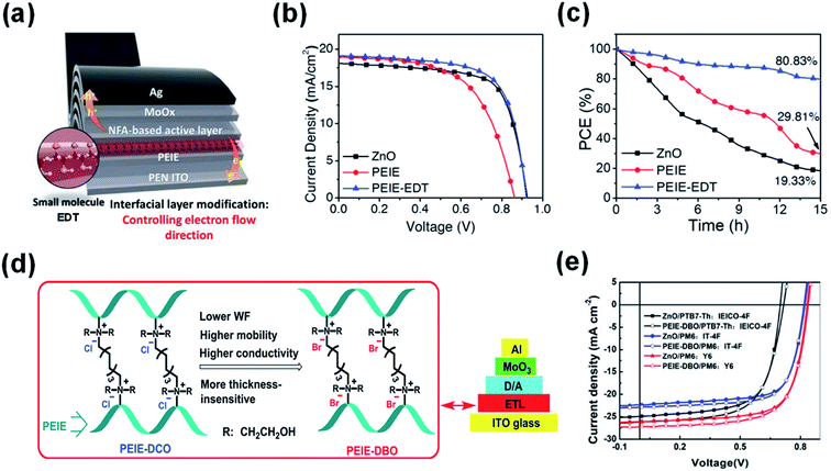 | ||
| Fig. 15 (a) Modifying the PEIE interface using the EDT molecule; (b) J–V characteristics; and (c) photostability of the OSCs devices based on ZnO, PEIE, and PEIE-EDT interfaces, respectively; (d) schematic diagram of PEIE grafted by DBO and DCO, respectively; (e) J–V characteristics of the OSCs devices based on ZnO and PEIE-DBO as electron-collecting interfaces, respectively. Reproduced from ref. 80 with permission from the Wiley, copyright [2021]. Reproduced from ref. 81 with permission from the Elsevier, copyright [2020]. | ||
3.3 Developing other chemically stable ETLs
To obtain a stable interface between the ETL and NFAs, novel ETLs were reported in the literature. Li et al.82 designed and synthesized a reaction-inert rylene diimide-embedded hyperbranched polymer named PDIEIE (Fig. 16a). PDIEIE shows negligible chemical reaction with high-performance photoactive materials and no catalytic effect under strong ultraviolet illumination. OSCs with PDIEIE maintained an initial efficiency of 28% after 100 h of continuous UV light irradiation, while the reference device based on ZnO and SnO2 only maintained 14% and 16% of its initial performance under the same conditions. Kyeong et al.83 developed a series of benzene functionalized PEIs by protecting the reactive amine functional groups (Fig. 16b). By using functionalized PEIs with broad work function tunability and improved chemical stability, nonfullerene OSCs obtained high PCE values over 15% and also thermally stable device operation for more than 360 h at 100 °C. Son et al.84 (Fig. 16c) developed new interlayer polymers of PDMA(N)EMA and PDMA(N–O)EMA. The devices incorporating PDMA(N)EMA showed a PCE of 8.19%, which was substantially enhanced compared with the 4.54% PCE of an PEIE-based device. Furthermore, the suppression of degradation at the PDMA(N)EMA interface also improved device stability at elevated temperatures. OSCs with PDMA(N)EMA maintained an initial efficiency of 84% under thermal annealing at 50 °C for 25 h, while the reference device based on PEIE only maintained 70% of its initial performance under the same conditions.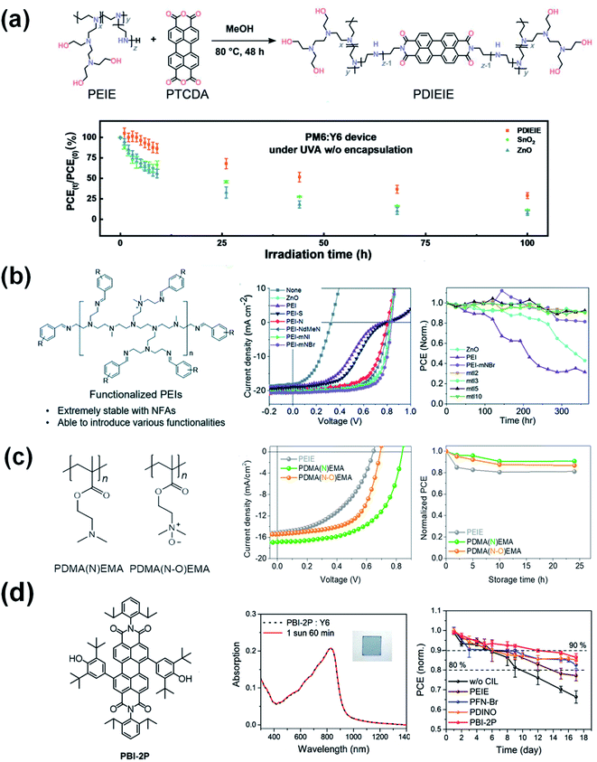 | ||
| Fig. 16 (a) The schematic diagram of the synthesis of PDIEIE. The photo-stability test for a PM6:Y6 device without encapsulation under UVA-340 light at 5 mW cm−2; (b) chemical structure of benzene functionalized PEIs. J–V characteristics. Thermal stability of the devices with the different ETLs annealed at 100 °C in a dry air atmosphere; (c) chemical structures of PDMA(N)EMA and PDMA(N-O)EMA. J–V characteristics. Thermal stability of the devices with the ETLs annealed at 50 °C in a N2 glove box. Reproduced from ref. 82 and 84 with permission from the Elsevier, copyright [2022] and [2021], respectively. Reproduced from ref. 83 with permission from the Royal Society of Chemistry, copyright [2021]. (d) Chemical structure of PBI-2P. UV-vis absorption spectra of the PBI-2P:Y6 blend film under continuous AM 1.5G illumination for 60 min. Decay of the OSCs with PBI-2P, PFN-Br, PDINO, and PEIE interlayers under continuous 25 W white-LED light irradiation in a nitrogen-filled glovebox. Reproduced from ref. 85 with permission from the Wiley, copyright [2022]. | ||
Another new type of amine-free small molecule composed of 2,6-di-tert-butyl-phenolfunctionalized perylene bisimide (PBI-2P) is also successfully applied as an ETL for nonfullerene OSCs.85 The stable contact between the PBI-2P and Y6 greatly enhances the interfacial stability compared to conventional amine-group functionalized interlayers of PEIE, PFN-Br, and PDINO. Moreover, nonfullerene OSCs based on the PBI-2P show good stability compared to amino-group functionalized interlayers (Fig. 16d). This work demonstrates a promising design principle of amine-free ETLs based on pigment chromophores containing the 2,6-di-tert-butylphenoxy groups which are prone to be ultra-chemically stable for nonfullerene OSC.
Nian et al.86 synthesized water-processable organosilica nanodots (OSiND) as an ETL through a hydrothermal method and achieved devices with excellent efficiency and photostability (Fig. 17a–c). Compared with the performance of the ZnO reference device, the efficiency of the PBDB-T-2F:Y6:PC71BM-based OSCs with OSiNO was improved to 17.15%. More importantly, the stability of the devices was effectively enhanced. OSCs based on the OSiND interfacial layer maintained an initial efficiency of 96.1% after 600 min of continuous AM1.5 G light irradiation, while the reference device based on ZnO only maintained 67.2% of its initial performance under the same conditions (Fig. 17a and b). The OSiND-based devices had good photostability without light-induced shunting and photocatalytic effects (Fig. 17c).
 | ||
| Fig. 17 (a) With ZnO ETL; (b) with OSiND ETL; (c) the evolution of PCEs for the devices under continuous illumination. Reproduced from ref. 86 with permission with Wiley, copyright [2020]. | ||
The discussion above is mostly on the interfacial chemical reactions in inverted nonfullerene OSCs. It is obvious that the amine groups in PEI/PEIE are the origin of the chemical reaction. For devices in a conventional structure, similar interactions also exist which is detrimental to the device performance. For example, Hou et al.87 compared poly[(9,9-bis(3′-(N,N-dimethylamino)propyl)-2,7-fluorene)-alt-2,7-(9,9-dioctylflu-orene)] (PFN) and its derivative (PFN-Br, Fig. 18a) used in fullerene-based and nonfullerene-based OSCs in a conventional device structure. PFN contains amine groups while PFN-Br turns the amine (in PFN) into quaternary ammonium. As shown in Fig. 18b, PFN and PFN-Br delivered similar performance when applied in fullerene-based OSCs. However, the photovoltaic performance is quite different in nonfullerene OSCs (PBDB-T-2F:IT-4F). When the interlayer is PFN, an ‘‘S’’-shape was observed in the J–V characteristic under illumination. When the interlayer is changed to PFN-Br, the device showed high performance without such an “S”-shape. This phenomenon is quite similar to that observed in the nonfullerene OSCs with PEIE/PEI as interlayers in the inverted configuration, stating that pronated PEI/PEIE can suppress the “S”-shape in J–V characteristics in inverted nonfullerene OSCs.41,47 Thus, managing the interaction between the ETL and NFA is important for nonfullerene OSCs in both inverted and conventional structures. To avoid detrimental reactions between the ETL and NFAs, self-doping strategies inside the ETL are adopted by grafting electron-deficient perylene diimide (PDI) or naphthalene diimide (NDI) moieties with amine groups, such as aliphatic amine-functionalized perylene-diimide (PDINN)88 and (N,N-dimethylamino)propyl naphthalene diimide (NDI-N).89
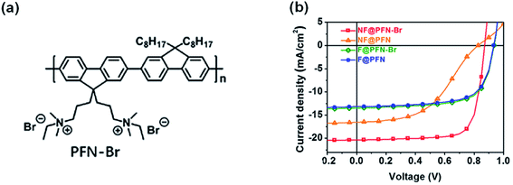 | ||
| Fig. 18 (a) Chemical structure of PFN-Br. (b) J–V characteristics of fullerene and nonfullerene OSCs with a PFN or PFN-Br interface, respectively. Reproduced from ref. 87 with permission with Elsevier, copyright [2020]. | ||
On the basis of the above content, we have classified and summarized the three strategies and related research to improve the interfacial chemical reactions in nonfullerene OSCs in following Table 1.
| Interfacial reaction | Strategies | Examples | |
|---|---|---|---|
| Chemical reaction | (1) Designing new NFAs | (i) Adopting ring-locked C![[double bond, length as m-dash]](https://www.rsc.org/images/entities/char_e001.gif) C vinyl linker C vinyl linker |
IDTT-R, IDTT-CR,78… |
(ii) Removing the C![[double bond, length as m-dash]](https://www.rsc.org/images/entities/char_e001.gif) C vinyl linker C vinyl linker |
All-fused-ring of ITYM,79… | ||
| (2) Interfacial modification | (i) Protonation of the amino group | a-PEIE,47 PEIE-CO2,47 PEIE-phosphoric acid,47… | |
| (ii) Chelation of metallic elements | PEI-Zn,43 ultra-thin PEIE-ITO,48… | ||
| (iii) Chelation of small molecules | PEIE-EDT,80 PEIE-DBO,81… | ||
| (3) Developing other chemically stable ETLs | (i) Modification the amine group | PEI-Zn,43 PDIEIE,82 functionalized PEIEs,83 PDMA(N)EMA,84 PBI-2P,85 PFN-Br,87… | |
| (ii) Designing other chemically stable ETLs | OSiOD,86… | ||
4. Strategies to suppress photochemical reactions
The photocatalytic effect is the key factor of ZnO inducing the photochemical decomposition of NFAs. The photocatalytic effect is associated with the defects of oxygen vacancies (VO+) and zinc interstitial atoms (Zni+). To suppress photochemical decomposition, one method is to modify ZnO to reduce its defect density or avoid the direct contact of ZnO and NFAs; the other approach is to develop other stable materials to replace ZnO as the electron-transporting layer.4.1 Modifying the surface of electron-transporting layer (ZnO)
Hu et al.49 used PEI aqueous solution to modify the ZnO surface (ZnO/a-PEI), and achieved much enhanced interfacial photostability of nonfullerene OSCs. After 1000 h of AM1.5 G (100 mW cm−2) irradiation, the efficiency of the device based on the ZnO ETL decayed to 43% of its initial value, while the efficiency of the ZnO/a-PEI device still maintained 75% of the initial value (Fig. 19a–c). The reason for the improved stability of the ZnO/a-PEI device was that the a-PEI could reduce the surface defects of ZnO, which was confirmed by the following measurements: (1) XPS analysis showed that the adsorption of oxygen on the ZnO surface was reduced; (2) Kelvin probe results showed that the work function recovery kinetics of ZnO/a-PEI was faster after UV light stopped; (3) the ESR spectrum showed that ZnO/a-PEI could effectively suppress the defect peaks of ZnO (VO+ and Zni+). The interaction between PEI and ZnO passivated the surface defects to reduce the adsorption of oxygen, thus reducing the concentration of free electrons in the ZnO conduction band produced under UV light, inhibiting the photocatalytic sites of the NFAs and the photocatalytic reaction, and finally obtaining devices with a high interface photostability.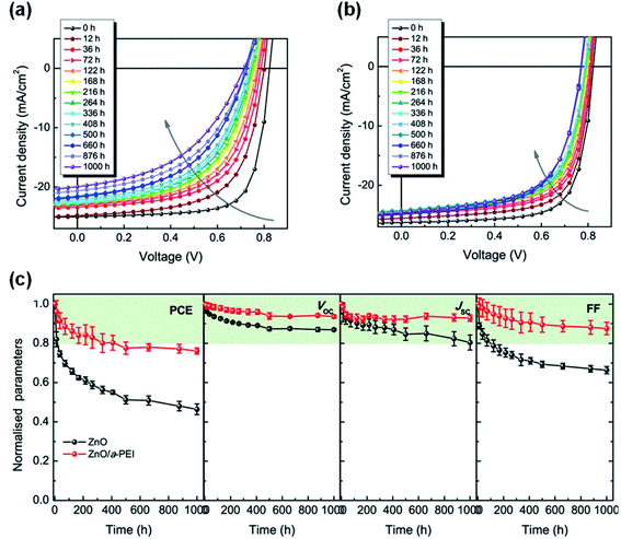 | ||
| Fig. 19 Evolution of J–V characteristics under continuous AM1.5 G illumination in a nitrogen-filled glovebox with: (a) ZnO and (b) ZnO/a-PEI ETL; (c) evolution of photovoltaic parameters of the devices under continuous AM1.5 G illumination. Reproduced from ref. 49 with permission from the American Chemical Society, copyright [2021]. | ||
Li et al.90 combined a small molecule of self-assembled monolayer materials (SAMs) to modify the ZnO interface (ZnO/SAMs) (Fig. 20a–c). The SAM1 of 4-((1,3-dioxoindan-2-ylidene)methyl)benzoic acid modification passivated the photocatalytic sites of ZnO, thereby improving the photostability of nonfullerene OSCs. Through continuous AM1.5 G light irradiation of devices with and without SAM1 modification, it was found that ZnO/SAM1 modified devices could maintain 70% of the initial performance after 180 h of light irradiation. In contrast, the ZnO-based devices only maintained 35% of the initial value under the same conditions (Fig. 20d). Yip et al.91 also used a self-assembled fullerene monolayer (C60-SAM) as a cathode modification layer to modify the ZnO surface. C60-SAM had dual functions: suppressing charge recombination by passivating surface defects and stabilizing the bulk heterojunction morphology by reducing the surface energy of ZnO. The T80 lifetime of ITO/ZnO/C60-SAM/PTB7-Th:IEICO-4F/MoO3/Ag inverted OSCs was estimated to be 34![[thin space (1/6-em)]](https://www.rsc.org/images/entities/char_2009.gif) 000 h. Assuming the solar radiation intensity was 1500 kW h·m−2·per year, the potential lifetime of OSCs was 22 years (Fig. 20e).
000 h. Assuming the solar radiation intensity was 1500 kW h·m−2·per year, the potential lifetime of OSCs was 22 years (Fig. 20e).
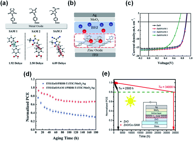 | ||
| Fig. 20 (a) Chemical structures and calculated dipole of three SAM molecules; (b) schematic illustration of electron extraction within SAM-modified inverted PSCs; (c) J–V characteristics; (d) device photostability under the constant 1 sun illumination with a metal halide lamp; (e) interfacial modification of the ZnO electron transparent layer with another C60-SAM can improve the efficiency and photostability of OSCs. Reproduced from ref. 90 with permission from the Wiley, copyright [2019]. Reproduced from ref. 91 with permission from the Chinese Academy of Sciences, copyright [2020]. | ||
Vasilopoulou et al.92 inserted pyrene-boron dipyrrole (Py-BDP) at the ZnO/active layer interface as an intermediate layer to suppress the catalytic degradation of NFAs caused by the photocatalytic activity of ZnO. As shown in Fig. 21a, Py-BDP does not have an amino group, so the interface chemical reaction with NFAs could be avoided. In addition, the donor–acceptor (D–A) structure of Py-BDP could realize effective charge transfer between the interfacial layer of ZnO and the active layer. The π-π interaction between the NFA and the bodipy part of Py-BDP facilitates charge transfer from the NFA toward pyrene, followed by ICT to the bodipy part and then to ZnO. After 540 min of continuous AM1.5 G irradiation in air at 25 °C and 40% relative humidity, the efficiency of the PBDB-T-2F:IT-4F based devices with ZnO decreased by 70% of its initial efficiency. In contrast, the efficiency of devices modified with Py-BDP only decreased 41% under the same conditions (Fig. 21b). The results showed that owing to the physical barrier formed between ZnO and IT-4F, the insertion of Py-BDP on ZnO ETL alleviated the photocatalytic-induced degradation of NFAs (Fig. 21c).
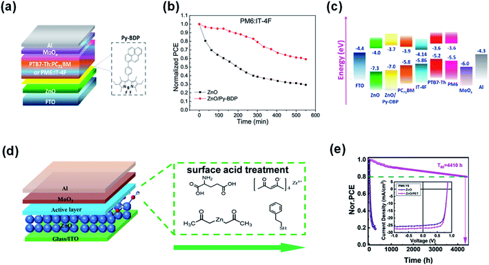 | ||
| Fig. 21 (a) Device structure of the OSCs; (b) photostability of unencapsulated OSCs with ZnO and ZnO/Py-BDP under constant AM 1.5G illumination for 9 h; (c) energy levels; (d) device structure of the OSCs and the molecular structures of TMAH, Zn(OAc)2, PET, ZrAcac, and GC; (e) PCE decay of the PM7:IT-4F and PM6:Y6 inverted solar cells with the pristine ZnO and PET-treated ZnO ETLs; inset shows the J–V curves of nonfullerene OSCs with and without PET modification. Reproduced from ref. 92 and 93 with permission from the American Chemical Society, copyright [2020] and [2021], respectively. | ||
Ma et al.93 believed that the hydroxyl on the ZnO surface was an important factor in the photocatalytic process, which would accelerate the degradation of NFAs at the ZnO/active layer interface. As shown in Fig. 21d, the acid treatment of the ZnO film could effectively remove the surface hydroxyl groups and greatly inhibit the interface degradation, thereby achieving high efficiency and great photostability of inverted nonfullerene OSCs. They chose different acidic materials, including zinc acetate (Zn(OAc)2), zirconium acetylacetonate (ZrAcac), glutamic acid (GC), and 2-phenylethyl mercaptan (PET) to process the ZnO film. Among them, PET was the most effective in improving the photostability of nonfullerene OSCs. The T80 lifetime of PBDB-T-2F:Y6 based OSCs with raw ZnO was less than 10 h. The devices with ZnO treated with PET showed significantly improved photostability and the T80 lifetime was more than 4000 h (Fig. 21e).
Recently, Forrest et al.94 tested several modification/buffer materials for enhancing device reliability (Fig. 22a). A carboxylic self-assembled monolayer (IC-SAM) and a 2 nm-thick C70 layer were applied at the ETL/active layer and HTL/active layer interfaces, respectively. The reference cell characteristics without the buffer layers decreased much faster, decreasing to less than 40% of their initial values within 2000 h illumination. However, devices with both cathode and anode buffers exhibited significantly improved stability, with PCE remaining 80% over 2000 h illumination. Encapsulated devices stabilized by additional protective buffer layers as well as the integration of an ultraviolet filtering layer maintained 94% of their initial efficiency under 1-sun, AM1.5G irradiation for 1900 h at 55 °C (Fig. 22b–e). Accelerated aging was also introduced by exposure of light illumination intensities up to 27 suns, and operation temperatures as high as 65 °C. An extrapolated intrinsic lifetime of >5.6 × 10⁴ h was obtained, which is equivalent to 30 years of outdoor exposure (Fig. 22f).
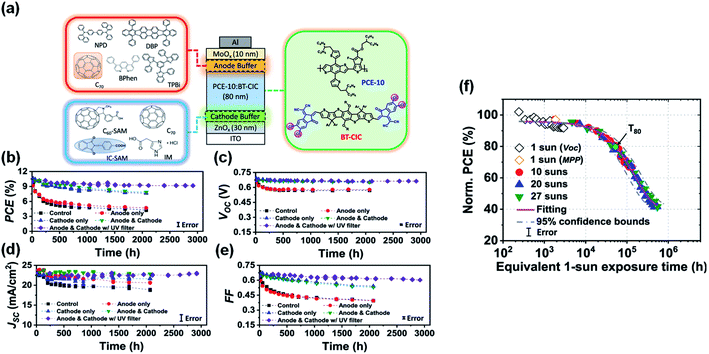 | ||
| Fig. 22 (a) Schematic of the device and molecular structures of the cathode and anode buffer materials; (b) PCE; (c) VOC; (d) JSC and (e) FF plotted vs. aging time under 1-sun AM1.5G illumination for 3000 h with different device architectures; (f) normalized PCE plotted vs. the equivalent 1-sun exposure time. Reproduced from ref. 94 with permission from the Nature Publishing Group, copyright [2021]. | ||
4.2 Developing other photochemically stable ETLs
In addition to modifying ZnO to suppress its photocatalytic performance on NFAs, there is another efficient method to replace ZnO with other metal oxides or organic compounds. The band gap of ZnO is 3.3 eV and can absorb UV light to generate free charge carriers, which is the cause of its photocatalytic effect. Therefore, metal oxides with a wider band gap can be used as the ETL. Jiang et al.46 used the wide gap semiconductor SnO2, which does not absorb ultraviolet light, to replace ZnO as the ETL, and achieved the stability improvement of nonfullerene OSCs under AM1.5 G light. Under UV light, ZnO would cause a decrease in work function due to surface oxygen desorption. However, SnO2 was relatively stable. These factors enable nonfullerene OSCs based on nanocrystalline SnO2 to show better photostability than the ones based on ZnO (Fig. 23a–c).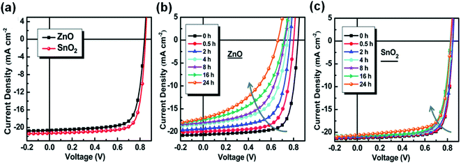 | ||
| Fig. 23 (a) J–V characteristics; (b and c) evolution of the J–V characteristics of cells under continuous AM1.5 G illumination: (b) with the ZnO ETL and (c) the SnO2 ETL, respectively. Reproduced from ref. 46 with permission from the Royal Society of Chemistry, copyright [2019]. | ||
Recently, Hou et al.95 designed and synthesized a new type of UV-resistant cathode interfacial layer (CIL) material NDI-B based on the naphthalene diimide (NDI) unit to replace ZnO. Nonfullerene OSCs with NDI-B achieved a PCE of 17.2% and excellent photostability. NDI-B had strong absorption in the UV region (Fig. 24a and b). On the one hand, when NDI-B was brought into contact with the polymer donor, additional photocurrent was generated, so the photocurrent of the device was enhanced; on the other hand, NDI-B could protect the active layer from UV decomposition (Fig. 24d). The NDI-B devices could retain 93% of their initial PCE after 1800 h of continuous exposure to AM1.5 G light. In contrast, the PCE of the ZnO device decreased to 5.8% of the initial value after 700 h light irradiation (Fig. 24c). The T80 lifetime of the NDI-B device was 200 times longer than the T80 lifetime of the ZnO reference device.
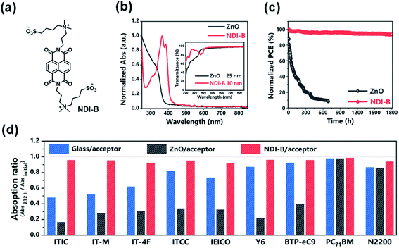 | ||
| Fig. 24 (a) Chemical structure of NDI-B; (b) normalized absorption spectra of ZnO and NDI-B as films. The inset shows their transmittance spectra; (c) photostability of the devices with ZnO and NDI-B as the ETLs. The encapsulated cells were measured in air under the illumination of AM1.5 G, 100 mW cm−2. The temperature was 45–55 °C; (d) remaining percent of absorption intensity for each acceptor after illumination by UV light for 232 h. Each acceptor was deposited on glass, glass/ZnO and glass/NDI-B substrates. Reproduced from ref. 95 with permission from the Chinese Chemical Society, copyright [2021]. | ||
PEIE is a commonly used electron collecting interfacial layer in fullerene OSCs. However, due to the interfacial chemical reaction in nonfullerene OSCs, it is necessary to use ultra-thin PEIE (1.2 nm) as the interfacial layer to achieve good device performance for Y6-series based nonfullerene active layers.48 Since the PEIE interfacial layer does not absorb UV light and has no photocatalytic effect, nonfullerene OSCs with PEIE as the interfacial layer have excellent photostability. After 100 h of continuous AM1.5 G light irradiation, the PCE of devices with PEIE was about 82% of the initial value. In contrast, the PCE of the reference cell with ZnO was only about 46% of the initial value.
On the basis of the above content, we have classified and summarized the two strategies and the related research to improve the interfacial photochemical reactions in nonfullerene OSCs in following Table 2.
| Interfacial reaction | Strategies | Examples | |
|---|---|---|---|
| Photochemical reaction | (1) Surface modification | (i) Add physical buffer layer | ZnO/Py-BDP,92… |
| (ii) Add chemical modification layer | ZnO/a-PEI,49 ZnO/SAM1,90 ZnO/C60-SAM,91 ZnO/PET,93 ZnO/IC-SAM,94 | ||
| (2) Developing other photochemically stable ETLs | (i) Other photochemically stable ETLs | SnO2,46 NDI-B,95 ultra-thin PEIE,48… | |
5. Conclusions and outlooks
This perspective concentrates on the description and discussion of interface stability issues in nonfullerene organic solar cells. Interface instability is caused by the interaction between the active layers and interfacial layers and degrades the device performance and operational stability. The C![[double bond, length as m-dash]](https://www.rsc.org/images/entities/char_e001.gif) C vinyl linker between the donor moiety and acceptor moiety is chemically reactive and is the weak point for interface stability. It is prone to react with inorganic or organic bases (such as NaOH or PEI) via chemical addition, and tends to break on the ZnO surface under UV or even visible light illumination. These reactions change the material and electronic structure at the interface, and deteriorate charge transport and device performance.
C vinyl linker between the donor moiety and acceptor moiety is chemically reactive and is the weak point for interface stability. It is prone to react with inorganic or organic bases (such as NaOH or PEI) via chemical addition, and tends to break on the ZnO surface under UV or even visible light illumination. These reactions change the material and electronic structure at the interface, and deteriorate charge transport and device performance.
Methods generally adopted to analyze the chemical and photochemical stability of NFAs include: (1) to test the chemical stability, a model compound of ethanolamine is added into NFA solutions in different mole ratios. Optical absorption, mass spectroscopy and nuclear magnetic resonance (NMR) are used as tools to analyze the solution products. An in situ test of the absorption and NMR can reflect the kinetics of the reactions and therefore the chemical reactivities of the NFAs and the amines; (2) to test the interfacial photochemical stability, a very thin (approximately 5–10 nm) film of NFA is coated on top of the ZnO layer. After continuous UV illumination, the resulting products are then analyzed via optical absorption and mass spectroscopy. These methods can reveal the reaction mechanism of NFAs with typically used electron-transporting interfaces, such as ZnO or amine-containing materials.
Modifying the chemical structure of NFAs can effectively enhance the chemical stability of the C![[double bond, length as m-dash]](https://www.rsc.org/images/entities/char_e001.gif) C linkers. For example, Y6-series acceptors show better chemical stability than ITIC-series via introducing an electron-deficient thiadiazole into the central electron-donating moiety.45 Alcohol-processed PEIE can as an efficient electron collecting interface for Y6 if the PEIE is reduced to about 1.2 nm, while such PEIE cannot work well with IT-4F based nonfullerene active layers.48 Recently, it is further reported that removal of the C
C linkers. For example, Y6-series acceptors show better chemical stability than ITIC-series via introducing an electron-deficient thiadiazole into the central electron-donating moiety.45 Alcohol-processed PEIE can as an efficient electron collecting interface for Y6 if the PEIE is reduced to about 1.2 nm, while such PEIE cannot work well with IT-4F based nonfullerene active layers.48 Recently, it is further reported that removal of the C![[double bond, length as m-dash]](https://www.rsc.org/images/entities/char_e001.gif) C vinyl linker in the NFA via new chemical design and synthesis can significantly enhance the interface stability.79 Since the interfacial reaction is mutual, another method to suppress the interfacial reaction is by modifying or changing the interface layer. Strategies of protonating the amine-containing interfacial layer or chelating with metal ions or modifying the ZnO surface have been validated effective for improving the interface stability.
C vinyl linker in the NFA via new chemical design and synthesis can significantly enhance the interface stability.79 Since the interfacial reaction is mutual, another method to suppress the interfacial reaction is by modifying or changing the interface layer. Strategies of protonating the amine-containing interfacial layer or chelating with metal ions or modifying the ZnO surface have been validated effective for improving the interface stability.
This perspective mainly focuses on the stability of the electron-transporting interface. In addition to the electron-transporting interface, the hole-transporting interface is also important to device performance and stability. MoO3 and PEDOT:PSS are generally used as hole-transporting layers. It is reported that under light illumination, Mo6+ of MoO3 is partially reduced to Mo5+ and degrades the device stability.94,96 PEDOT:PSS is a polymer complex with several reactive factors, including water, acidity, oxidative properties, and sometimes wetting agents. Though A–D–A NFAs show much better stability under acid than basic conditions, it is reported that the PEDOT:PSS surface can also cause the decomposition of ITIC under continuous illumination and result in device performance deterioration.97 The PEDOT:PSS can also react with the 1,8-diiodooctane (DIO) additive in the nonfullerene active layer due to the oxidative and acidic properties of PEDOT:PSS.98 More studies should be performed on the interface stability of the hole transporting interface for achieving stable organic solar cells.
Author contributions
P. J., L. H. and L. L. S. prepared the first draft of the perspective. Y. H. Z., Z. A. L. and H. W. H. supervised the preparation of the perspective.Conflicts of interest
There are no conflicts to declare.Acknowledgements
This work was supported by the National Natural Science Foundation of China (Grant nos. 51973074, 51773072 and 61804060), the China Postdoctoral Science Foundation funded project (2019M662614 and 2020M682404), and the WNLO funds for innovation.Notes and references
- A. Mishra and P. Bauerle, Angew. Chem., Int. Ed., 2012, 51, 2020–2067 CrossRef CAS PubMed
.
- A. J. Sneyd, T. Fukui, D. Paleček, S. Prodhan, I. Wagner, Y. Zhang, J. Sung, S. M. Collins, T. J. A. Slater, Z. A. Garmaroudi, L. R. MacFarlane, J. D. G. Hernandez, L. Wang, G. R. Whittell, J. M. Hodgkiss, K. Chen, D. Beljonne, I. Manners, R. H. Friend and A. Rao*, Sci. Adv., 2021, 7, 1–10 Search PubMed
.
- V. Romano, G. D'Angelo, S. Perathoner and G. Centi, Energy Environ. Sci., 2021, 14, 5760–5787 RSC
.
- G. Zhang, J. Zhao, P. C. Y. Chow, K. Jiang, J. Zhang, Z. Zhu, J. Zhang, F. Huang and H. Yan, Chem. Rev., 2018, 118, 3447–3507 CrossRef CAS PubMed
.
- G. Yu, J. Gao, J. C. Hummelen, F. Wudl and A. J. Heeger, Science, 1995, 270, 1789–1791 CrossRef CAS
.
- A. Wadsworth, M. Moser, A. Marks, M. S. Little, N. Gasparini, C. J. Brabec, D. Baran and I. McCulloch, Chem. Soc. Rev., 2019, 48, 1596–1625 RSC
.
- A. Armin, W. Li, O. J. Sandberg, Z. Xiao, L. Ding, J. Nelson, D. Neher, K. Vandewal, S. Shoaee, T. Wang, H. Ade, T. Heumüller, C. Brabec and P. Meredith, Adv. Energy Mater., 2021, 11, 2003570 CrossRef CAS
.
- E. M. Speller, A. J. Clarke, J. Luke, H. K. H. Lee, J. R. Durrant, N. Li, T. Wang, H. C. Wong, J.-S. Kim, W. C. Tsoi and Z. Li, J. Mater. Chem. A, 2019, 7, 23361–23377 RSC
.
- J. J. M. Halls, C. A. Walsh, N. C. Greenham, E. A. Marseglia, R. H. Friend, S. C. Moratti and A. B. Holmes, Nature, 1995, 376, 498–500 CrossRef CAS
.
- G. Yu, J. Gao, J. C. Hummelen and A. J. H. F. Wudi, Science, 1995, 270, 1789–1791 CrossRef CAS
.
- Z. He, C. Zhong, S. Su, M. Xu, H. Wu and Y. Cao, Nat. Photonics, 2012, 6, 591–595 CrossRef
.
- J. Zhao, Y. Li, G. Yang, K. Jiang, H. Lin, H. Ade, W. Ma and H. Yan, Nat. Energy, 2016, 1, 1–7 Search PubMed
.
- J. Zhang, L. Zhu and Z. Wei, Small Methods, 2017, 1, 1700258 CrossRef
.
- Y. Lin, J. Wang, Z. G. Zhang, H. Bai, Y. Li, D. Zhu and X. Zhan, Adv. Mater., 2015, 27, 1170–1174 CrossRef CAS PubMed
.
- Y. Lin, F. Zhao, Q. He, L. Huo, Y. Wu, T. C. Parker, W. Ma, Y. Sun, C. Wang, D. Zhu, A. J. Heeger, S. R. Marder and X. Zhan, J. Am. Chem. Soc., 2016, 138, 4955–4961 CrossRef CAS PubMed
.
- S. Li, L. Ye, W. Zhao, S. Zhang, S. Mukherjee, H. Ade and J. Hou, Adv. Mater., 2016, 28, 9423–9429 CrossRef CAS PubMed
.
- W. Li, L. Ye, S. Li, H. Yao, H. Ade and J. Hou, Adv. Mater., 2018, 30, 707170 Search PubMed
.
- D. Qian, Z. Zheng, H. Yao, W. Tress, T. R. Hopper, S. Chen, S. Li, J. Liu, S. Chen, J. Zhang, X. K. Liu, B. Gao, L. Ouyang, Y. Jin, G. Pozina, I. A. Buyanova, W. M. Chen, O. Inganas, V. Coropceanu, J. L. Bredas, H. Yan, J. Hou, F. Zhang, A. A. Bakulin and F. Gao, Nat. Mater., 2018, 17, 703–709 CrossRef CAS PubMed
.
- J. Hou, O. Inganäs, R. H. Friend and F. Gao, Nat. Mater., 2017, 17, 119–128 CrossRef PubMed
.
- J. Yuan, Y. Zhang, L. Zhou, G. Zhang, H. L. Yip, T. K. Lau, X. Lu, C. Zhu, H. Peng, P. A. Johnson, M. Leclerc, Y. Cao, J. Ulanski, Y. Li and Y. Zou, Joule, 2019, 3, 1140–1151 CrossRef CAS
.
- Q. Liu, Y. Jiang, K. Jin, J. Qin, J. Xu, W. Li, J. Xiong, J. Liu, Z. Xiao, K. Sun, S. Yang, X. Zhang and L. Ding, Sci. Bull., 2020, 65, 272–275 CrossRef CAS
.
- Y. Lin, M. I. Nugraha, Y. Firdaus, A. D. Scaccabarozzi, F. Aniés, A. H. Emwas, E. Yengel, X. Zheng, J. Liu, W. Wahyudi, E. Yarali, H. Faber, O. M. Bakr, L. Tsetseris, M. Heeney and T. D. Anthopoulos, ACS Energy Lett., 2020, 5, 3663–3671 CrossRef CAS
.
- Y. Lin, Y. Firdaus, F. H. Isikgor, M. I. Nugraha, E. Yengel, G. T. Harrison, R. Hallani, A. El-Labban, H. Faber, C. Ma, X. Zheng, A. Subbiah, C. T. Howells, O. M. Bakr, I. McCulloch, S. D. Wolf, L. Tsetseris and T. D. Anthopoulos, ACS Energy Lett., 2020, 5, 2935–2944 CrossRef CAS
.
- Y. Cui, H. Yao, J. Zhang, K. Xian, T. Zhang, L. Hong, Y. Wang, Y. Xu, K. Ma, C. An, C. He, Z. Wei, F. Gao and J. Hou, Adv. Mater., 2020, 32, 1908205 CrossRef CAS PubMed
.
- L. Liu, S. Chen, Y. Qu, X. Gao, L. Han, Z. Lin, L. Yang, W. Wang, N. Zheng, Y. Liang, Y. Tan, H. Xia and F. He, Adv. Mater., 2021, 33, 2101279 CrossRef CAS PubMed
.
- L. Zhan, S. Li, X. Xia, Y. Li, X. Lu, L. Zuo, M. Shi and H. Chen, Adv. Mater., 2021, 33, 2007231 CrossRef CAS PubMed
.
- F. Liu, L. Zhou, W. Liu, Z. Zhou, Q. Yue, W. Zheng, R. Sun, W. Liu, S. Xu, H. Fan, L. Feng, Y. Yi, W. Zhang and X. Zhu, Adv. Mater., 2021, 33, 2100830 CrossRef CAS PubMed
.
- P. Bi, S. Zhang, Z. Chen, Y. Xu, Y. Cui, T. Zhang, J. Ren, J. Qin, L. Hong, X. Hao and J. Hou, Joule, 2021, 06, 020 Search PubMed
.
- C. Li, J. Zhou, J. Song, J. Xu, H. Zhang, X. Zhang, J. Guo, L. Zhu, D. Wei, G. Han, J. Min, Y. Zhang, Z. Xie, Y. Yi, H. Yan, F. Gao, F. Liu and Y. Sun, Nat. Energy, 2021, 6, 605–613 CrossRef CAS
.
- J. Wang, Z. Zheng, Y. Zu, Y. Wang, X. Liu, S. Zhang, M. Zhang and J. Hou, Adv. Mater., 2021, 33, 2102787 CrossRef CAS PubMed
.
- https://www.nrel.gov/pv/cell-efficiency.html .
- N. Li, I. McCulloch and C. J. Brabec, Energy Environ. Sci., 2018, 11, 1355–1361 RSC
.
- Q. Burlingame, M. Ball and Y.-L. Loo, Nat. Energy, 2020, 5, 947–949 CrossRef
.
- X. Xu, D. Li, J. Yuan, Y. Zhou and Y. Zou, Energy Chem, 2021, 3, 100046 CrossRef CAS
.
- H. Lee, C. Park, D. H. Sin, J. H. Park and K. Cho, Adv. Mater., 2018, 1800453 CrossRef PubMed
.
- L. Duan and A. Uddin, Adv. Sci., 2020, 7, 1903259 CrossRef CAS PubMed
.
- K. Wang, Y. Li and Y. Li, Macromol. Rapid Commun., 2020, 41, 1900437 CrossRef CAS PubMed
.
- Y. Wang, J. Lee, X. Hou, C. Labanti, J. Yan, E. Mazzolini, A. Parhar, J. Nelson, J. S. Kim and Z. Li, Adv. Energy Mater., 2020, 11, 2003002 CrossRef
.
- S. Park, T. Kim, S. Yoon, C. W. Koh, H. Y. Woo and H. J. Son, Adv. Mater., 2020, 32, 2002217 CrossRef CAS PubMed
.
- J. Zhang, H. S. Tan, X. Guo, A. Facchetti and H. Yan, Nat. Energy, 2018, 3, 720–731 CrossRef CAS
.
- L. Hu, Y. Liu, L. Mao, S. Xiong, L. Sun, N. Zhao, F. Qin, Y. Jiang and Y. Zhou, J. Mater. Chem. A, 2018, 6, 2273–2278 RSC
.
- Y. Zhou, C. F. Hernandez, J. Shim, J. Meyer, A. J. Giordano, H. Li, P. Winget, T. Papadopoulos, H. Cheun, J. Kim, M. Fenoll, A. Dindar, W. Haske, E. Najafabadi, T. M. Khan, H. Sojoudi, S. Barlow, S. Graham, J. L. Brédas, S. R. Marder, A. Kahn and B. Kippelen, Science, 2012, 336, 327–332 CrossRef CAS PubMed
.
- F. Qin, W. Wang, L. Sun, X. Jiang, L. Hu, S. Xiong, T. Liu, X. Dong, J. Li, Y. Jiang, J. Hou, K. Fukuda, T. Someya and Y. Zhou, Nat. Commun., 2020, 11, 4508 CrossRef PubMed
.
- X. Zhu, L. Hu, W. Wang, X. Jiang, L. Hu and Y. Zhou, ACS Appl. Energy Mater., 2019, 2, 7602–7608 CrossRef CAS
.
- L. Hu, S. Xiong, W. Wang, L. Sun, F. Qin and Y. Zhou, J. Phys. Chem. C, 2020, 124, 2307–2312 CrossRef CAS
.
- Y. Jiang, L. Sun, F. Jiang, C. Xie, L. Hu, X. Dong, F. Qin, T. Liu, L. Hu, X. Jiang and Y. Zhou, Mater. Horiz., 2019, 6, 1438–1443 RSC
.
- S. Xiong, L. Hu, L. Hu, L. Sun, F. Qin, X. Liu, M. Fahlman and Y. Zhou, Adv. Mater., 2019, 31, 1806616 CrossRef PubMed
.
- W. Zeng, X. Zhou, B. Du, L. Hu, C. Xie, W. Wang, Y. Jiang, T. Wang and Y. Zhou, Adv. Energy and Sustainability Research, 2021, 2, 2000094 CrossRef
.
- L. Hu, Y. Jiang, L. Sun, C. Xie, F. Qin, W. Wang and Y. Zhou, J. Phys. Chem. Lett., 2021, 12, 2607–2614 CrossRef CAS PubMed
.
- L. Sun, W. Zeng, C. Xie, L. Hu, X. Dong, F. Qin, W. Wang, T. Liu, X. Jiang, Y. Jiang and Y. Zhou, Adv. Mater., 2020, 32, 1907840 CrossRef CAS PubMed
.
- H. Liu, Y. Li, S. Xu, Y. Zhou and Z. a. Li, Adv. Funct. Mater., 2021, 31, 2106735 CrossRef CAS
.
- S. Li, L. Ye, W. Zhao, S. Zhang, S. Mukherjee, H. Ade and J. Hou, Adv. Mater., 2016, 28, 9423–9429 CrossRef CAS PubMed
.
- J. Hou, O. Inganas, R. H. Friend and F. Gao, Nat. Mater., 2018, 17, 119–128 CrossRef CAS PubMed
.
- J. Yuan, Y. Zhang, L. Zhou, G. Zhang, H. L. Yip, T. K. Lau, X. Lu, C. Zhu, H. Peng, P. A. Johnson, M. Leclerc, Y. Cao, J. Ulanski, Y. Li and Y. Zou, Joule, 2019, 3, 1140–1151 CrossRef CAS
.
- Y. Sun, J. H. Seo, C. J. Takacs, J. Seifter and A. J. Heeger, Adv. Mater., 2011, 23, 1679–1683 CrossRef CAS PubMed
.
- Z. He, C. Zhong, S. Su, M. Xu, H. Wu and Y. Cao, Nat. Photonics, 2012, 6, 591–595 CrossRef
.
- M. Afzaal and P. O'Brien, J. Mater. Chem., 2006, 16, 1597–1602 RSC
.
- F. Rahman, Opt. Eng., 2019, 58, 1 Search PubMed
.
- P. Zhang, J. Wu, T. Zhang, Y. Wang, D. Liu, H. Chen, L. Ji, C. Liu, W. Ahmad, Z. D. Chen and S. Li, Adv. Mater., 2018, 30, 1703737 CrossRef PubMed
.
- W. Huang, L. Zeng, X. Yu, P. Guo, B. Wang, Q. Ma, R. P. H. Chang, J. Yu, M. J. Bedzyk, T. J. Marks and A. Facchetti, Adv. Funct. Mater., 2016, 26, 6179–6187 CrossRef CAS
.
- Y. Chen, W. Huang, V. K. Sangwan, B. Wang, L. Zeng, G. Wang, Y. Huang, Z. Lu, M. J. Bedzyk, M. C. Hersam, T. J. Marks and A. Facchetti, Adv. Mater., 2019, 31, 1805082 CrossRef PubMed
.
- W. Huang, P. Guo, L. Zeng, R. Li, B. Wang, G. Wang, X. Zhang, R. P. H. Chang, J. Yu, M. J. Bedzyk, T. J. Marks and A. Facchetti, J. Am. Chem. Soc., 2018, 140, 5457–5473 CrossRef CAS PubMed
.
- W. Tress and O. Inganäs, Sol. Energy Mater. Sol. Cells, 2013, 117, 599–603 CrossRef CAS
.
- S. Trost, K. Zilberberg, A. Behrendt, A. Polywka, P. Görrn, P. Reckers, J. Maibach, T. Mayer and T. Riedl, Adv. Energy Mater., 2013, 3, 1437–1444 CrossRef CAS
.
- F. Jiang, T. Liu, B. Luo, J. Tong, F. Qin, S. Xiong, Z. Li and Y. Zhou, J. Mater. Chem. A, 2016, 4, 1208–1213 RSC
.
- A. Houas, H. Lachheb, M. Ksibi, E. Elaloui, C. Guillard and J.-M. Herrmann, Appl. Catal., B, 2001, 31, 145–157 CrossRef CAS
.
- K. M. Lee, C. W. Lai, K. S. Ngai and J. C. Juan, Water Res., 2016, 88, 428–448 CrossRef CAS PubMed
.
- C. B. Ong, L. Y. Ng and A. W. Mohammad, Renewable Sustainable Energy Rev., 2018, 81, 536–551 CrossRef CAS
.
- A. F. Kohan, G. Ceder and D. Morgan, Phys. B, 2000, 61, 15019–15027 CAS
.
- F. Oba, S. R. Nishitani, S. Isotani and H. Adachi, J. Appl. Phys., 2001, 90, 824–828 CrossRef CAS
.
- D. C. Look, C. Coşkun, B. Claflin and G. C. Farlow, Phys. B, 2003, 340–342, 32–38 CrossRef CAS
.
- H. Omura, H. Kumomi, K. Nomura, T. Kamiya, M. Hirano and H. Hosono, J. Appl. Phys., 2009, 105, 093712 CrossRef
.
- S. R. Cowan, P. Schulz, A. J. Giordano, A. Garcia, B. A. MacLeod, S. R. Marder, A. Kahn, D. S. Ginley, E. L. Ratcliff and D. C. Olson, Adv. Funct. Mater., 2014, 24, 4671–4680 CrossRef CAS
.
- S. Park and H. J. Son, J. Mater. Chem. A, 2019, 7, 25830 RSC
.
- B. Liu, Y. Han, Z. Li, H. Gu, L. Yan, Y. Lin, Q. Luo, S. Yang and C. Q. Ma, Sol. RRL, 2020, 5, 2000638 CrossRef
.
- Z. X. Liu, Z. P. Yu, Z. Shen, C. He, T. K. Lau, Z. Chen, H. Zhu, X. Lu, Z. Xie, H. Chen and C. Z. Li, Nat. Commun., 2021, 12, 3049 CrossRef CAS PubMed
.
- Y. Che, M. R. Niazi, R. Izquierdo and D. F. Perepichka, Angew. Chem., Int. Ed., 2021, 60, 24833–24837 CrossRef CAS PubMed
.
- H. Liu, W. Wang, Y. Zhou and Z. Li, J. Mater. Chem. A, 2021, 9, 1080–1088 RSC
.
- X. Zhu, S. Liu, Q. Yue, W. Liu, S. Sun and S. Xu, CCS Chem., 2021, 3, 1070–1080 CrossRef CAS
.
- A. Prasetio, M. Jahandar, S. Kim, J. Heo, Y. H. Kim and D. C. Lim, Adv. Sci., 2021, 8, 2100865 CrossRef CAS PubMed
.
- Z. Zhang, Z. Zhang, Y. Yu, B. Zhao, S. Li, J. Zhang and S. Tan, J. Energy Chem., 2020, 47, 196–202 CrossRef
.
- Y. Li, T. Li, J. Wang, X. Zhan and Y. Lin, Sci. Bull., 2022, 67, 171–177 CrossRef CAS
.
- M. Kyeong, J. Lee, M. Daboczi, K. Stewart, H. Yao, H. Cha, J. Luke, K. Lee, J. R. Durrant, J.-S. Kim and S. Hong, J. Mater. Chem. A, 2021, 9, 13506–13514 RSC
.
- S. H. Park, S. Park, K. J. Lee, J. K. Kim and H. J. Son, Dyes Pigm., 2021, 194, 109523 CrossRef CAS
.
- X. Wen, Y. Zhang, G. Xie, R. Rausch, N. Tang, N. Zheng, L. Liu, F. Würthner and Z. Xie, Adv. Funct. Mater., 2022, 2111706 CrossRef
.
- M. Cui, D. Li, X. Du, N. Li, Q. Rong, N. Li, L. Shui, G. Zhou, X. Wang, C. J. Brabec and L. Nian, Adv. Mater., 2020, 32, 2002973 CrossRef CAS PubMed
.
- Q. Kang, Q. Wang, C. An, C. He, B. Xu and J. Hou, J. Energy Chem., 2020, 43, 40–46 CrossRef
.
- J. Yao, B. Qiu, Z. G. Zhang, L. Xue, R. Wang, C. Zhang, S. Chen, Q. Zhou, C. Sun, C. Yang, M. Xiao, L. Meng and Y. Li, Nat. Commun., 2020, 11, 2726 CrossRef CAS PubMed
.
- Q. Kang, L. Ye, B. Xu, C. An, S. J. Stuard, S. Zhang, H. Yao, H. Ade and J. Hou, Joule, 2019, 3, 227–239 CrossRef CAS
.
- H. Liu, Z. X. Liu, S. Wang, J. Huang, H. Ju, Q. Chen, J. Yu, H. Chen and C. Z. Li, Adv. Energy Mater., 2019, 9, 1900887 CrossRef
.
- X. Xu, J. Xiao, G. Zhang, L. Wei, X. Jiao, H. L. Yip and Y. Cao, Sci. Bull., 2020, 65, 208–216 CrossRef CAS
.
- A. Soultati, A. Verykios, S. Panagiotakis, K. K. Armadorou, M. I. Haider, A. Kaltzoglou, C. Drivas, A. Fakharuddin, X. Bao, C. Yang, A. Yusoff, E. K. Evangelou, I. Petsalakis, S. Kennou, P. Falaras, K. Yannakopoulou, G. Pistolis, P. Argitis and M. Vasilopoulou, ACS Appl. Mater. Interfaces, 2020, 12, 21961–21973 CrossRef CAS
.
- Y. Han, H. Dong, W. Pan, B. Liu, X. Chen, R. Huang, Z. Li, F. Li, Q. Luo, J. Zhang, Z. Wei and C. Q. Ma, ACS Appl. Mater. Interfaces, 2021, 13, 17869–17881 CrossRef CAS PubMed
.
- Y. Li, X. Huang, K. Ding, H. K. M. Sheriff, Jr., L. Ye, H. Liu, C. Z. Li, H. Ade and S. R. Forrest, Nat. Commun., 2021, 12, 5419 CrossRef CAS PubMed
.
- Q. Liao, Q. Kang, Y. Yang, Z. Zheng, J. Qin, B. Xu and J. Hou, CCS Chem., 2021, 3, 1059–1069 Search PubMed
.
- L. Yan, H. Gu, Z. Li, J. Zhang, Y. Yang, H. Wang, X. Liu, Z. Wei, Q. Luo and C. Q. Ma, Mater. Adv., 2020, 1, 1307–1317 RSC
.
- Y. Wang, W. Lan, N. Li, Z. Lan, Z. Li, J. Jia and F. Zhu, Adv. Energy Mater., 2019, 9, 1900157 CrossRef
.
- W. Wang, F. Qin, X. Zhu, Y. Liu, X. Jiang, L. Sun, C. Xie and Y. Zhou, ACS Appl. Mater. Interfaces, 2020, 12, 3800–3805 CrossRef CAS PubMed
.
Footnote |
| † These authors equally contributed to this perspective. |
| This journal is © The Royal Society of Chemistry 2022 |
