Interfacial built-in electric-field for boosting energy conversion electrocatalysis
Hui
Xu
 *a,
Junru
Li
b and
Xianxu
Chu
*b
aKey Laboratory of Advanced Catalytic Materials and Technology, Advanced Catalysis and Green Manufacturing Collaborative Innovation Center, Changzhou University, Changzhou, Jiangsu Province 213164, China. E-mail: xuhui006@cczu.edu.cn
bHenan Key Laboratory of Biomolecular Recognition and Sensing, College of Chemistry and Chemical Engineering, Shangqiu Normal University, Shangqiu 476000, Henan Province, P. R. China. E-mail: xxchu13633@163.com
First published on 30th January 2023
Abstract
The formation of a built-in electric field (BIEF) can induce electron-rich and electron-poor counterparts to synergistically modify electronic configurations and optimize the binding strengths with intermediates, thereby leading to outstanding electrocatalytic performance. Herein, a critical review regarding the concept, modulation strategies, and applications of BIEFs is comprehensively summarized, which begins with the fundamental concepts, together with the advantages of BIEF for boosting electrocatalytic reactions. Then, a systematic summary of the advanced strategies for the modulation of BIEF along with the in-detail mechanisms in its formation are also added. Finally, the applications of BIEF in driving electrocatalytic reactions and some cascade systems for illustrating the conclusive role from the induced BIEF are also systematically discussed, followed by perspectives on the future deployment and opportunity of the BIEF design.
1. Introduction
The energy crisis and environmental pollution are still persistent topics regarding the sustainability of human society. Considering the oncoming energy shortage and significant environmental deterioration, it is urgent to develop advanced materials with high renewable energy utilization and robust stability in industrial applications, which thus inevitably concerns thermodynamics or dynamics modulations over materials.1–5 In recent years, electrocatalytic energy conversion devices have been attracting increasing interest due to their high energy conversion efficiency and environmental friendliness.6–10As the core component of energy conversion devices, electrocatalysts play a crucial role in determining energy conversion efficiency. However, before practical application, some important issues regarding the electrocatalysts should also be well addressed.11–14 One is associated with electrocatalytic activity, where an electrocatalyst with high catalytic activity enables energy conversion devices to achieve high energy conversion efficiency.15–17 Another is correlated with electrochemical stability, which is also a crucial parameter for evaluating the catalytic performance of nanocatalysts and their promise for future applications.18–20 Besides, charge transfer capability is also a decisive factor affecting their catalytic performance since electrocatalytic processes are redox reactions involving electron gain and electron loss.21–23 Therefore, realizing efficient charge separation and migration during the electrochemical reaction is a key point to achieve significant improvement in electrocatalytic performance.
For example, constructing a metal–support interface is widely considered as a promising approach to achieve high catalytic performance, in which the metal can adsorb hydrogen and the support can promote the water dissociation and function as the real active sites to adsorb the hydroxide intermediates.24,25 However, the overlap of the electron cloud across the interface will drive the charge carriers to experience severe localization, resulting in limited electron transfer and poor catalytic performance. In recent years, creating an interfacial BIEF in a heterojunction will effectively relieve the electron cloud localization and induce the interfacial space charge and band bending to separate electrons and protons, thereby effectively altering the charge distribution and affecting the intermediate adsorption.26–28 Therefore, the creation and modulation of BIEF will greatly benefit for the efficient charge distribution and the substantial improvement in electrocatalytic performance.29 During the past decades, research into the BIEF displays an increase in the exponential term in widespread applications and multicomponent devices and many effective strategies have been proposed for the modification of BIEF for further optimizing the catalytic performance of metal–support catalysts. It was clearly found that some comprehensive reviews of BIEF in the field of photocatalysis have been well organized.30–32 However, a countable review or perspective on the BIEF for the application of electrocatalytic reactions has rarely been reported.
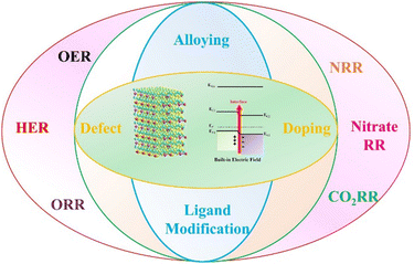
In this review, we organize a critical review of BIEF in electrocatalytic reactions by focusing on the fundamental concepts, modification strategies, and positive influences on the promotion of catalytic performance (Scheme 1). Some cascade systems for illustrating the origin of BIEF and its conclusive role in affecting catalytic performance are also systematically covered. After giving a detailed discussion for the BIEF, some advanced strategies for the modulation strategies, such as alloying, heteroatom doping, and defect engineering are also illustrated. Moreover, the widespread applications of BIEF in driving electrocatalytic reactions together with in-depth mechanisms are also comprehensively discussed, which will benefit for the expedition of BIEF-based mechanism research and material development in the future.
2. Fundamentals of the built-in electric-field
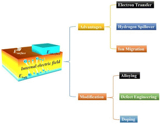
In essence, the BIEF is induced from a nonuniform charge distribution in the single-component material or at the heterointerface of the heterostructures. BIEF has been widely explored and investigated in the field of optoelectronic devices, solar energy cells, photocatalysis, etc. As is well known, the BIEF in the heterojunction can accelerate the separation efficiency of the photoexcited electron–hole pairs. The fast separation process of the photoexcited electron–hole pairs can thus lead to an ultrafast response speed.33 In addition, previous research also demonstrated that the formed BIEF can also suppress the majority of carrier diffusion and avoid trap-assisted-tunneling. In recent years, it has also been reported that BIEF can greatly affect the electrocatalytic performance of a heterostructured catalyst by inducing interfacial charge redistribution and optimizing the binding strengths of active sites and intermediates (Scheme 2).To make full utilization of BIEF, quantitative and qualitative analysis of the BIEF should be carried out. In general, the determination methods for scaling the accurate or relatively accurate intensity of the BIEF can be classified into the following types: “DFT calculation and mathematical simulations”, “zeta potential”, “surface photovoltage spectroscopy”, “scanning transmission electron microscopy”, and some newly emerging methods. In fact, for a specific feature derived from the BIEF, multiple methods can be employed to determine it. For example, a combination of DFT calculation and zeta potential has benefits for the quantitative or qualitative determination of the intensify of BIEF. For some electrocatalytic reactions, the applied potential may affect the BIEF by inhibiting the occurrence of electron transfer, thus affecting the catalytic performance. However, when an applied potential is lower than 0.3 V, it may hardly affect the BIEF. This is because the interfacial BIEF in a heterojunction will effectively relieve the electron cloud localization and induce the interfacial space charge and band bending to separate electrons and protons, effectively altering the charge distribution and affecting the intermediate adsorption. Therefore, the applied potential will not affect the BIEF and the catalytic performance.
The interfacial structure for BIEF includes the p–n heterojunction, p–p heterojunction, n–n heterojunction, Mott–Schottky heterojunction, and others. As is well known to all, each heterojunction (p–n, n–n, p–p, and Mott–Schottky heterojunction) has its own advantages. For example, the alkaline OER performance of transition metal compound-based heterostructure electrocatalysts is more prominent, and the neutral/acidic HER activity of noble-metal-based Mott–Schottky heterojunctions is superior. It is not clear which heterointerface is better. Therefore, it is necessary to distinguish the physiochemical properties of each heterojunction to take full advantages to improve the electrocatalytic performance.
In general, noble-metal-based materials can form Mott–Schottky heterojunctions, which exhibit superb catalytic performance for multiple reactions such as electrocatalytic OER, HER, ORR, fuel oxidation reactions, NRR, etc. Taking a metal-n-type semiconductor as an example, after contact, electrons will transfer from the n-type semiconductor to the metal due to the different work function and enrich the metal region. The electron flow hardly alters the Fermi energy of the metal due to its high-density pool of free electrons. Therefore, a space charge separation zone at the near-surface area of the semiconductor forms and then produces BIEF from the semiconductor to the metal. Transition metal compound-based materials with different types of semiconductors can generate p–n, n–n, and p–p heterojunctions, which are demonstrated to be beneficial for the promotion of electrocatalytic OER, NRR, CO2RR, and so on.
3. Modulation strategies toward the built-in electric-field
3.1 Alloying
Work function (Φ), defined as the minimum energy demanded to remove an electron from the Fermi level to the vacuum level, is a fundamental surface property of a material.34 In a binary metal–support catalyst, by tuning the ΔΦ between the metal and support, the charge transport orientation across the heterointerface will be greatly affected.35 As a result, the BIEF will also be greatly tailored, leading to modulation of the hydrogen and hydroxide adsorption. Therefore, focusing on tailoring the ΔΦ of the metal or support has been widely accepted in recent years. In regard to the modification of ΔΦ, one of the most effective strategies is alloying, which can decrease or increase the Φ of metal to largely reduce the ΔΦ between metal and support.For example, Qu et al.36 have systematically elevated the alloying strategy for modifying the ΔΦ between metal and support. By taking Pt/CoP as a model catalyst, the ΔΦ of ∼0.19 eV between Pt (ΦPt = 5.37 eV) and CoP (ΦCoP = 5.56 eV) can create a BIEF and induce a large energy barrier for hydrogen spillover from Pt to CoP, thereby delivering no synergistic enhancements in the electrocatalytic HER (Fig. 1(a)). After alloying Pt with some foreign metals, they found that the calculated Φ values for Pt-based alloys were obviously altered, where the calculated Φ for PtIr, PtRh, PtPd, PtAg, and PtAu was 5.54 eV, 5.33 eV, 5.40 eV, 5.18 eV and 5.34 eV, respectively (Fig. 1(b)). It is interestingly observed that the PtIr/CoP with the lowest Φ value of 0.02 eV is the most promising candidate for inducing efficient hydrogen spillover (Fig. 1(c)). A small ΔΦ can dilute the interfacial charge density and relocate the electrons to the metal and the support, thereby leading to weakened proton adsorption at the heterointerface and improving the proton adsorption on metals. Consequently, the PtIr/CoP catalyst with the smallest ΔΦ value of 0.02 eV can deliver the best HER performance.
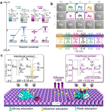 | ||
| Fig. 1 (a) A schematic presentation of the interfacial electronic configurations and hydrogen spillover phenomenon in metal–support binary catalysts. (b) Design of PtM/CoP model catalysts with the controllable ΔΦ. (c) Proposed nature of the ΔΦ on the hydrogen spillover phenomenon in the PtIr/CoP catalyst. Reproduced with permission from ref. 36, 2021, Nature Publishing Group. | ||
More recently, Qu et al.37 also reported the fabrication of RuFe/CoP nanocomposites and further investigated the alloying strategy for modulating the BIEF and Φ. Specifically, they synthesized a series of RuFe alloys deposited on CoP with different Ru/Fe atomic ratios. Alloying Ru with Fe can remodel the electronic configuration of the metal and exhibit a small ΔΦ value of 0.05 eV with a Ru/Fe atomic ratio of 1![[thin space (1/6-em)]](https://www.rsc.org/images/entities/char_2009.gif) :
:![[thin space (1/6-em)]](https://www.rsc.org/images/entities/char_2009.gif) 1 (Fig. 2(a)). In comparison with the poor HER activity of RuFe nanoparticles, the Ru1Fe1/CoP can deliver superb catalytic HER activity with an overpotential of 6 mV at 20 mA cm−2 and a Tafel slope of 24.5 mV dec−1. A deep mechanism study coupled with kinetic analyses uncovered that the small ΔΦ between Ru1Fe1 and CoP enabled the energetically favorable interfacial RuFe-to-CoP hydrogen spillover and well-designed BIEF, synergistically improving the electrocatalytic HER performance (Fig. 2(b) and (c)). According to this research, it is demonstrated that the alloying strategy is highly favorable for tuning the ΔΦ between the metal and support and inducing beneficial BIEF for synergistically promoting the catalytic performance.
1 (Fig. 2(a)). In comparison with the poor HER activity of RuFe nanoparticles, the Ru1Fe1/CoP can deliver superb catalytic HER activity with an overpotential of 6 mV at 20 mA cm−2 and a Tafel slope of 24.5 mV dec−1. A deep mechanism study coupled with kinetic analyses uncovered that the small ΔΦ between Ru1Fe1 and CoP enabled the energetically favorable interfacial RuFe-to-CoP hydrogen spillover and well-designed BIEF, synergistically improving the electrocatalytic HER performance (Fig. 2(b) and (c)). According to this research, it is demonstrated that the alloying strategy is highly favorable for tuning the ΔΦ between the metal and support and inducing beneficial BIEF for synergistically promoting the catalytic performance.
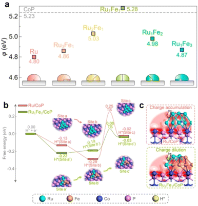 | ||
| Fig. 2 (a) A summary of the calculated Φ values of RuFe alloys with different Ru/Fe atomic ratios. (b) The calculated free energy diagram for hydrogen spillover on Ru/CoP and Ru1Fe1/CoP. (c) Electron density difference map of interfaces. Reproduced with permission from ref. 37, 2022, American Chemical Society. | ||
3.2 Defect engineering
The creation of defect sites in the materials can form different electronic surface barriers, causing changes in the work function and BIEF. For example, the existence of oxygen vacancies in the Pt/TiO2 catalyst can greatly promote the hydrogen spillover process, making the hydrogen transfer easier.38 Ramani et al.39 synthesized Pb2Ru2O7−x with rich oxygen vacancies through air calcination. The work function of Pb2Ru2O7−x can be reduced by increasing the oxygen vacancy concentration. In addition to oxygen deficiency sites, the construction of sulfur deficiency sites can also effectively regulate their work functions. Chen et al.40 created rich sulfur defect sites through the strategy of doping Cu in SnS2, and the generation of sulfur defect sites can effectively reduce the work function of SnS2. In the metal sulfide composite catalyst, the construction of sulfur defect sites can affect the dipole moment of the metal carrier interface, accelerate the rearrangement of the atomic structure of the interface and lead to electron transfer (Fig. 3(a)–(c)). With the increase of sulfur defect site concentration, the dipole moment of the interface gradually decreases, leading to weakening of the work function change trend, and the change trend of the effective work function of the interface also tends to be gentle. It can be seen that the concentration of sulfur defect sites has a significant impact on the work function of transition metal sulfide and lead to the modification of BIEF (Fig. 3(d) and (e)).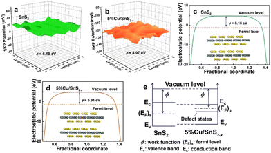 | ||
| Fig. 3 (a) and (b) Relative work function maps, (c) and (d) calculated work function and (e) a schematic illustration of Fermi level variation. Reproduced with permission from ref. 40, 2021, Elsevier. | ||
3.3 Valence state engineering
Valence state engineering is also another promising strategy for tuning the Φ values of support. As is well known, the Φ value of support is greatly affected by many important factors, such as the crystal phase, valence state, and coordination environment of active metals. Valence state engineering is an easy and highly effective method for realizing Φ modification to form well-designed BIEFs. Taking Fan's work41 as a model example, they systematically investigated the intrinsic correlation between Φ and BIEF by evaluating the catalytic performance of a series of Pt-based metal–support catalysts. Specifically, they employed Cu as a sacrificial agent with strong oxygen affinity to precisely tailor the oxidation state of CoOx (Fig. 4(a)), which strongly affects the ΔΦ with Pt. After a systematic and deep investigation, they revealed that the ΔΦ played a crucial role in affecting the BIEF, where a large ΔΦ can induce an enhanced BIEF (Fig. 4(b)–(d)). Interestingly, the enhanced BIEF played a key role in subtly modifying the H* and OH* adsorption strength (Fig. 4(e)–(g)), which was essential for the promotion of HER activity in neutral solution. As a result, an overpotential of merely 82 mV is required for achieving 10 mA cm−2.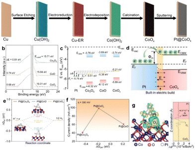 | ||
| Fig. 4 (a) A schematic illustration of the synthesis of Pt@CoOx. (b) UPS spectra and (c) the energy-band alignment diagram of CoO, CoOx, and Co3O4 with respect to Pt. (d) A schematic illustration of the Schottky junction. (e) Adsorption free energies of H* on Pt@CoOx and some referenced samples. (f) Adsorption free energies of OH* on Pt@CoOx and some referenced samples. (g) Isosurfaces of charge density difference (left) and planar-average charge density plot (right) of Pt@CoOx. Reproduced with permission from ref. 41, 2022, Wiley-VCH. | ||
4. Applications
4.1 Oxygen evolution reaction
Up to now, multitudinous efforts have been dedicated to manipulating the surface properties of electrocatalysts to further promote the catalytic OER performance. As indicated by semiconductor physics, fabricating heterojunction systems with two or more semiconductors with different energy structures can lead to the generation of BIEF and two opposite charge distribution regions at the heterointerface.42–49 The formed BIEF can boost the electron transport and affect the adsorption of reactants or intermediated species. Therefore, a heterojunction with strong BIEF will be favorable for substantial improvement in the electrocatalytic OER performance, and many interesting strategies have been proposed.Inspired by these motivations, Yang et al.50 have reported the construction of a p–p NiSe2/FeSe2 heterojunction by using Fe–Ni PBA as the precursor (Fig. 5(a) and (b)). Electrochemical measurements revealed that the p–p NiSe2/FeSe2 heterojunction could exhibit superb catalytic performance towards OER and the urea oxidation reaction (UOR), requiring an overpotential of merely 266 mV at 10 mA cm−2 (Fig. 5(c)). The comprehensive characterizations and mechanism study demonstrated that the well-created BIEF at the heterointerface of the p–p NiSe2/FeSe2 heterojunction expedited the charge transfer and strengthened the electrical conductivity of the heterojunction catalyst. More importantly, the self-driven electron transfer across the NiSe2/FeSe2 heterointerface can induce local charge redistribution at the interface region, which is favorable for the adsorption of OH− due to the electrostatic interaction.
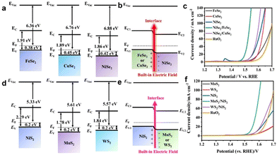 | ||
| Fig. 5 (a) Schematic diagrams of the band structure of FeSe2, CoSe2, and NiSe2 electrocatalysts at the frequency of 1 kHz. (b) Schematic diagrams of the band structure of FeSe2, CoSe2, and NiSe2 before and after contact. (c) OER polarization curves of different catalysts. (d) Mott–Schottky plots of NiS2, MoS2, and WS2 electrocatalysts at the frequency of 1 kHz. (e) Schematic diagrams of the band structure of NiS2, MoS2, and WS2 before and after contact. (f) OER polarization curves of different catalysts. (a)–(c) Reproduced with permission from ref. 50, 2021, Elsevier. (d)–(f) Reproduced with permission from ref. 33, 2022, Elsevier. | ||
More recently, Liu et al.33 also reported that the interfacial engineering of the metal sulfides heterostructure with BIEF could also further promote the catalytic OER performance. Specifically, they reported the synthesis of MoS2/NiS2 and WS2/NiS2, which showed the overpotentials as low as 300 mV and 320 mV to achieve 10 mA cm−2, respectively (Fig. 5(d)–(f)), which was comparable with commercial RuO2. The experiments uncovered that the fabricated heterostructured catalysts with spontaneously developed BIEF and strong electronic interaction based on the difference of the band structure promoted the interfacial charge transfer and improved the absorptivity of OH−, thereby leading to the substantial improvement in electrocatalytic OER performance.
In addition to promoting the charge transfer across heterointerfaces, the created BIEF in the heterojunction can also promote catalytic OER performance by accelerating the surface reconstruction. As demonstrated by Song and coworkers,51 they reported a BIEF-induced surface reconstruction strategy for realizing ultrafast self-activation of metal sulfides in self-supporting CoS2/CuS heterostructures (Fig. 6(a)). Remarkably, the CoS2/CuS heterostructured catalysts can deliver outstanding catalytic activity for OER with ultralow overpotentials of 136 mV and 266 mV at 10 and 100 mA cm−2, respectively (Fig. 6(b)). By combining the theoretical calculations and in situ technologies, it is elucidated that the BIEF within heterointerfaces can significantly promote the surface reconstruction of (oxy)hydroxide species by decreasing the formation energy. Also, the reconstructed active sites on the surface can regulate the catalytic behaviors, especially for the rate-determining step (Fig. 6(c) and (d)), thereby accounting for the superb catalytic OER performance.
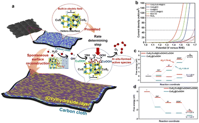 | ||
| Fig. 6 (a) A schematic illustration of the catalytic mechanism. (b) OER polarization curves of different electrocatalysts. (c) The theoretical free energy diagrams of CoS2/CuS@CoOOH/CuOOH and CoS2@CoOOH at applied potentials of 0 and 1.23 V in the OER process. (d) The theoretical free energy diagrams of CoS2/CuS@CoOOH/CuOOH and CoS2@CoOOH at applied potentials of 1.76 and 1.88 V in the OER process. (a)–(c) Reproduced with permission from ref. 51, 2022, Cell Press. | ||
4.2 Hydrogen evolution reaction
Constructing the BIEF can induce charge redistribution at the heterointerfaces to optimize the adsorption with H*, thereby contributing to the substantial improvement in electrocatalytic HER performance.52–55 In recent years, fabricating BIEF has been widely accepted as a promising strategy for promoting the electrocatalytic HER performance of heterostructured catalysts. For example, Yan et al.56 synthesized the MXene supported MoNi4 alloy nanocrystals catalysts with a remarkably strong BIEF at the heterointerface of two components, which benefited for the electron transfer from MXene to MoNi4. Owing to the accumulation of electrons at the MoNi4 sites, the adsorption of catalytic intermediates and ionic species on the MoNi4 alloy is greatly affected. As a consequence, the hybrid can exhibit superb catalytic HER activity by delivering a low overpotential and a small Tafel slope of 55.88 mV dec−1.As previously discussed, creating BIEF can promote the charge transfer and hydrogen spillover from one component to another, which is thus favorable for weakening or strengthening the H* affinity.57–65 For instance, Yan et al.66 synthesized a 2D heterostructure from growing NiPS3 on the surface of Ni2P to boost the electrocatalytic HER. According to the DFT calculations, it is revealed that the NiPS3/Ni2P heterojunction can greatly decrease the kinetic barrier for hydrogen adsorption and accelerate the electron transfer due to the formed BIEF at the epitaxial interfaces (Fig. 7(a)–(c)). Consequently, benefitting from these favorable terms, such a NiPS3/Ni2P heterojunction can deliver superb HER activity, with the overpotential of 85 mV at 10 mA cm−2 and the Tafel slope of 82 mV dec−1 (Fig. 7(d) and (e)). These advanced works have proved that the creation of BIEF can induce the redistribution of the interfacial charge to optimize the binding strength with the intermediates, thereby contributing to the substantial improvement in catalytic performance.
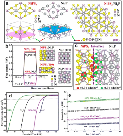 | ||
| Fig. 7 (a) Schematic models to illustrate the lattice matching between NiPS3 and Ni2P. (b) ΔGH* calculated at the equilibrium potential (U = 0 V) for the NiPS3/Ni2P, Ni2P(001), Ni2P(110), and NiPS3(110), and the insets are the corresponding DFT-optimized configurations of H* adsorption. (c) Distribution of the charge density difference at the NiPS3/Ni2P interface. (d) HER polarization curves and (e) Tafel plots of different electrocatalysts. (a)–(c) Reproduced with permission from ref. 66, 2019, American Chemical Society. | ||
4.3 Oxygen reduction reaction
The oxygen reduction reaction (ORR) is a crucial reaction for many important energy conversion technologies, such as fuel cells, metal–air batteries, and so on.67–71 Therefore, the ORR performance of a catalyst is of vital significance for determining their energy conversion efficiencies.72–77 Tremendous explorations have been carried out to develop advanced ORR catalysts or effective strategies for promoting the catalytic performance of inherent catalysts.In recent years, fabricating heterostructured catalysts with strong BIEFs has been accepted as a promising approach for achieving outstanding catalytic performance due to the nature of charge redistribution and electron transfer.78–81 Taking Liu's work82 as a good example, they synthesized Mott–Schottky Co/Co2P heterojunction nanoparticles encapsulated in the shell of N,P-codoped carbon nanotubes (Fig. 8(a) and (b)). Interestingly, the Schottky effect of the metal–semiconductor heterojunction affords a BIEF at the heterointerface to enhance the electron transport, meanwhile, the intertwined structure of 1D N,P-codoped carbon also facilitated the mass transfer of the intermediated species (Fig. 8(c) and (d)). As a result, such a Mott–Schottky heterojunction with a BIEF can exhibit superb catalytic activity towards ORR, for which the onset potential (EO), half-wave potential (E1/2) and limiting current density are 1.00 V, 0.88 V and 6.2 mA cm−2, respectively (Fig. 8(e) and (f)). According to previous work, it is interestingly found that the BIEF in the Mott–Schottky heterojunction is of vital importance for improving the electrocatalytic ORR performance by facilitating the interfacial electron transfer and mass transport.
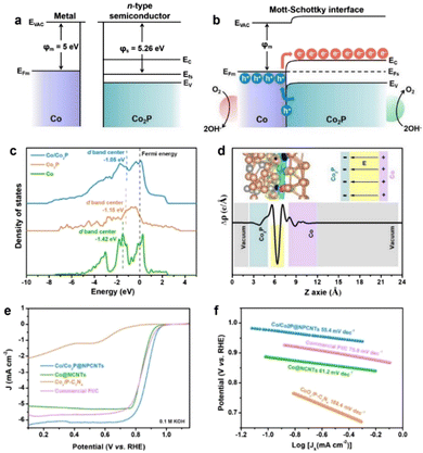 | ||
| Fig. 8 Energy band diagrams for Co metal and n-type Co2P semiconductor (a) before and (b) after Schottky contact. (c) Density of states (DOS) for Co/Co2P, Co and Co2P models. (d) Charge density difference for the Co/Co2P heterojunction. (e) ORR polarization curves and (f) Tafel plots of different electrocatalysts. (a)–(c) Reproduced with permission from ref. 82, 2021, Elsevier. | ||
4.4 Nitrogen reduction reaction
The electrocatalytic nitrogen reduction reaction (NRR) has widely been considered as a potential technology for yielding NH3 under ambient conditions.83 However, electrocatalytic NRR suffers from poor efficiency of NH3 production, where N2 adsorption and activation require large electricity energy.84–86 Recent research has reported that the electric field effect can promote the catalytic activity and selectivity of the nanocatalysts as the engineered BIEFs not only greatly altered the interfacial charge distribution of the metal active sites but also significantly affected the adsorbing behaviors of the reactants and intermediated species.87,88 Inspired by the positive influence of BIEF on the promotion of the electrocatalytic performance towards water splitting and ORR, BIEFs also hold great promise for substantially promoting the electrocatalytic performance towards NRR. For example, Yan et al.26 reported the fabrication of a CoO–Co3O4 heterostructure with interfacial electric fields to boost electrocatalytic NRR (Fig. 9(a)–(i)). According to the theoretical calculations and in situ techniques, it was uncovered that the engineered strong interfacial electric field in the CoO–Co3O4 heterostructure ccould effectively capture the inert N2 by forming strong Co–N bonds. Additionally, the interfacial electric field could also significantly enhance the σ–d orbital hybridization between the Co site and N2 molecule, being favorable for activating the N2 molecules (Fig. 9(j)). As a result, the as-prepared CoO–Co3O4 heterostructure could exhibit a promising NH3 yield of 59.96 μg h−1 mgcat−1 and high faradaic efficiency (FE) of 22.37% in 0.1 M Li2SO4, confirming the great promise of the interfacial electric field for substantial improvement in electrocatalytic NRR.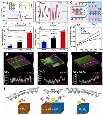 | ||
| Fig. 9 (a) Charge density difference and (b) electrostatic potential profile for CoO–Co3O4. (c) A schematic of the interface charge transfer process in the CoO–Co3O4 heterostructure. (d) The Zeta potentials, (e) surface charge, and (f) intense distributions of electric field of CoO, Co3O4 and CoO–Co3O4. (g)–(i) The 3D surface potential distribution and corresponding line scanning surface potential profile of CoO, Co3O4 and CoO–Co3O4. (j) A schematic diagram presenting the interfacial electric field engineered in CoO–Co3O4 heterostructure for boosting electrocatalytic NRR. Reproduced with permission from ref. 26, 2023, Elsevier. | ||
4.5 Nitrate reduction reaction
In recent years, low-concentration nitrate in surface and ground water has been increasing as vast amounts of nitrous oxides are being emitted from fossil fuel combustion, which causes increasing damage to the environment and human lives.81,89 Therefore, nitrate removal from water and its subsequent conversion to highly valuable products is now attracting great interest. Ammonia, as one of the primary fertilizers, is mainly synthesized via the Haber–Bosch process, which will inevitably lead to large energy consumption.90 Recently, using hydrogen from water to catalyze nitrate reduction to ammonia is a highly effective strategy for not only alleviating environmental pollution but also yielding high-value products.91,92 As a key component of electrocatalytic reactions, electrocatalysts play a decisive role in determining the reaction efficiency and rate. Therefore, developing efficient electrocatalysts with high catalytic activity and selectivity is highly important for achieving desirable catalytic efficiency.It has been previously reported that the construction of simple metal–support catalysts can deliver high catalytic activity towards nitrate reduction reaction. However, their low selectivity, low faradaic efficiency, and the release of toxic byproducts means they are unsatisfactory nitrate reduction catalysts.93,94 Taking these factors into consideration, tremendous explorations have been made and some effective strategies have been proposed. Among them, constructing BIEFs in heterostructured catalysts has been revealed to be a promising strategy for realizing superb performance. It is reported that the creation of BIEFs can largely accumulate a higher concentration of NO3− near the electrocatalyst surface region, which will thus facilitate the mass transfer of reagent for nitrate removal and subsequent electrochemical reduction to ammonia. As proved by Lu’ work,32 the BIEFs in the heterostructured catalyst can lead to a significant improvement in catalytic activity and selectivity for nitrate reduction to ammonia (Fig. 10(a) and (b)). Specifically, they have stacked the CuCl(111) and rutile TiO2(110) layers together to form a BIEF induced by the electron transfer from TiO2 to CuCl (Fig. 10(c) and (g)). By integrating the theory calculation with characterizations, they uncovered that the BIEFs could effectively induce interfacial accumulation of NO3− around the surface of the electrocatalyst and increase the energy of the *NO intermediate (Fig. 10(h) and (i)). As a result, an ultrahigh selectivity of 98.6% for NH3, together with a low NO2− production of <0.6% was achieved for the optimized CuCl/TiO2 (Fig. 10(j) and (k)).
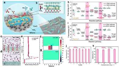 | ||
Fig. 10 (a) A scheme of the BIEF in situ formed on the MXene surface. (b) Differential charge density of BIEF. (c) and (d) Molecular dynamics simulation of CuCl BIEF and CuCl in KNO3 (100 mg![[thin space (1/6-em)]](https://www.rsc.org/images/entities/char_2009.gif) L−1) solution. Scale bar: 0.5 nm. (e) Distribution of NO3− along the z-axis electrode distance. (f) and (g) Finite element analysis of ions distribution difference near CuCl BIEF and CuCl in KNO3 solution. (h) and (i) Reaction pathways for NO3− reduction to NH3 on the surface of CuCl BIEFs and pure CuCl. (j) Seven consecutive recycling tests at −1.0 V. (k) Selectivity of ammonia with different initial NO3− concentrations. Reproduced with permission from ref. 32, 2021, Wiley-VCH. L−1) solution. Scale bar: 0.5 nm. (e) Distribution of NO3− along the z-axis electrode distance. (f) and (g) Finite element analysis of ions distribution difference near CuCl BIEF and CuCl in KNO3 solution. (h) and (i) Reaction pathways for NO3− reduction to NH3 on the surface of CuCl BIEFs and pure CuCl. (j) Seven consecutive recycling tests at −1.0 V. (k) Selectivity of ammonia with different initial NO3− concentrations. Reproduced with permission from ref. 32, 2021, Wiley-VCH. | ||
More recently, Wang et al.95 also demonstrated that a well-designed BIEF can accelerate the nitrate electroreduction kinetics and optimize the chemisorption of nitrate ions or intermediates. They have reported the synthesis of CuO@MnO2 core–shell hierarchical arrays with abundant heterointerfaces and well-constructed BIEF. Benefitting from the heterostructured geometric advantages, facilitated mass transfer, and efficient electron transfer induced by BIEF, the CuO@MnO2 arrays can display an impressive catalytic nitrate-to-ammonia capability with a nitrate conversion of 99.38%, a FE of 94.92%, and ammonia selectivity of 96.67%.
4.6 CO2 reduction reaction
The electrocatalytic CO2 reduction reaction not only alleviates the damaged “greenhouse effect” but also produces some value-added products and thus emerges as a promising technology owing to its high-efficiency utilization and recycling of carbon sources.96–99 However, the bond length of C![[double bond, length as m-dash]](https://www.rsc.org/images/entities/char_e001.gif) O is perceptibly shorter than the C–O single bond, and the energy required to dissociate a C
O is perceptibly shorter than the C–O single bond, and the energy required to dissociate a C![[double bond, length as m-dash]](https://www.rsc.org/images/entities/char_e001.gif) O bond in CO2 is as high as 800 kJ mol−1, rendering CO2 as the chemically inert atmosphere.100,101 Therefore, the CO2 molecules can hardly be activated to participate in reactions unless under the assistance of effective electrocatalysts. Traditional catalytic processes include the adsorption, activation, and conversion of CO2 molecules, the major drawback of high energy demands for the transfer of CO2 molecules to active sites has limited the conversion rate to value-added chemical products. In recent years, electricity-driven CO2 reduction reactions involved a multiple proton-coupled electron transfer process and thus showed great advantages for industrial applications.102,103 In addition, constructing heterostructured catalysts with BIEFs is also conducive to the substantial promotion in catalytic performance towards the CO2 reduction reaction.104 For one thing, the BIEFs in the heterointerface will facilitate the adsorption or desorption of the intermediates. For another, BIEFs in the heterophase interface are reported to be beneficial for boosting the electron transfer and mass transport, ultimately elevating the intrinsic activity.
O bond in CO2 is as high as 800 kJ mol−1, rendering CO2 as the chemically inert atmosphere.100,101 Therefore, the CO2 molecules can hardly be activated to participate in reactions unless under the assistance of effective electrocatalysts. Traditional catalytic processes include the adsorption, activation, and conversion of CO2 molecules, the major drawback of high energy demands for the transfer of CO2 molecules to active sites has limited the conversion rate to value-added chemical products. In recent years, electricity-driven CO2 reduction reactions involved a multiple proton-coupled electron transfer process and thus showed great advantages for industrial applications.102,103 In addition, constructing heterostructured catalysts with BIEFs is also conducive to the substantial promotion in catalytic performance towards the CO2 reduction reaction.104 For one thing, the BIEFs in the heterointerface will facilitate the adsorption or desorption of the intermediates. For another, BIEFs in the heterophase interface are reported to be beneficial for boosting the electron transfer and mass transport, ultimately elevating the intrinsic activity.
As proven by Fu and coworkers,105 the heterophase and BIEFs engineering can largely promote the catalytic performance towards CO2 reduction. Specifically, they have synthesized the sheet-like heterophase SnO2/Sn3O4 with a high density of heterointerfaces and BIEFs (Fig. 11(a)). The evidence from experiments and theoretical calculations suggested that the charge redistribution induced by BIEFs could accelerate the charge transfer between active sites and reactants (Fig. 11(b)), as well as boosted the CO2 adsorption and conversion to HCOO* (Fig. 11(c) and (d)). As a result, a high faradaic efficiency of HCOOH conversion of 88.3% was achieved, which confirmed the positive influence of BIEFs on the substantial improvement in catalytic activity and selectivity towards CO2 conversion.
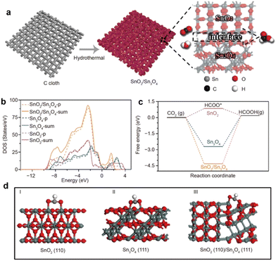 | ||
| Fig. 11 (a) A schematic diagram presenting the synthetic procedures of the SnO2/Sn3O4 with BIEFs. (b) Density of state of the p- and sum-orbital of the SnOx catalysts. (c) Optimized adsorption configurations of CO2 on SnOx catalysts. (d) The calculated free energy diagrams of the electrocatalytic CO2RR into HCOOH. Reproduced with permission from ref. 105, 2020, Springer. | ||
5. Conclusions and perspectives
In summary, BIEF is essentially formed due to the nonuniform charge distribution in the single crystal or at the heterointerface between various constituent layers, affording a powerful force to drive charge separation and migration. As a result, efficient charge separation and migration will undoubtedly affect the catalytic process and lead to variation of catalytic performance. In recent years, BIEF has played an increasingly important role in affecting catalytic HER performance via facilitating the charge transfer and hydrogen spillover to optimize the binding strength with intermediates. Therefore, the construction or amelioration of the BIEF will play a robust role as a driving force to steer the substantial promotion of catalytic performance. In this review, we have summarized the general factors that induce the BIEF, including alloying, heteroatom doping, defect engineering, and so on, together with the discussions about the fundamentals of BIEF. Subsequently, a deep discussion about the positive influence of BIEF on the promotion of catalytic performance is also systematically provided.Overviewing throughout this review, it can be clearly found that BIEF benefits for the substantial promotion of catalytic performance. Although great progress has been achieved over the past decades, some challenging issues still need to be addressed in the near future.
5.1 Distinguishing the effect of BIEF for inducing hydrogen spillover
First, it is well accepted that BIEF is favorable for boosting the interfacial charge transfer to optimize the binding strength with intermediates. For HER, it is also reported that the construction of BIEF will also benefit for intensifying the hydrogen spillover to further optimize the H* Gibbs free energy. Besides the electron transfer and hydrogen spillover, the other roles of BIEF during electrocatalytic reactions need to be determined. More endeavors should be dedicated to the exploration of the more important roles that BIEF plays to guide the modification of BIEF for further promoting the catalytic performance.5.2 Advanced techniques to analyze BIEF
Second, the existing techniques still suffer from intrinsic limitations or shortcomings and advanced quantitative analysis of the BIEF is still deficient. To date, the most widely used technologies for analyzing BIEFs are UPS and XPS; however, they are not precise. Therefore, paying more attention to the exploration of advanced technologies for characterizing BIEFs will significantly boost the development and application of BIEFs.5.3 Combining theoretical investigations and in situ characterizations to reveal the real role of BIEF in electrocatalytic performance
Third, the BIEF is constructed between different components and is favorable for the electron transfer during electrochemical reactions. However, the advantageous merits of abundant catalytically active sites and the strong synergistic effect in the heterostructured catalysts are also conducive to substantial improvement in catalytic performance. How can we distinguish the positive influence of BIEF and the synergistic effect? It is still challenging. Some in situ characterization techniques should be operated, accompanied by theoretical stimulations. According to in situ characterizations, it can be clearly found that there is an electron transfer pathway through the interface induced by BIEF. Moreover, in situ characterizations could also be beneficial for confirming the formation of the Schottky junction to boost catalytic reactions. Therefore, integrating in situ technologies and DFT calculations will be beneficial for gaining a better understanding into the influence of BIEF on catalytic performance.5.4 Advanced synthesis of electrocatalysts with strong BIEFs
Finally, the existing strategies for modifying the BIEF are heteroatom doping, alloying, defect engineering, and so on. However, these potential methods have still scarcely been researched and are still inadequate. More efforts should be devoted to the exploration of more efficient strategies for realizing the modification of BIEF.We believe once these points for the BIEF are well addressed, not only the design of well-performed advanced materials but also some fundamental mechanisms in the fields of electrocatalysis will be greatly promoted.
Conflicts of interest
There are no conflicts to declare.Acknowledgements
This work is supported by the start-up funding to H. Xu by Changzhou University (ZMF22020055) and Advanced Catalysis and Green Manufacturing Collaborative Innovation Center (ACGM2022-10-01), Changzhou University for financial support.Notes and references
- S. Chen, J. Zhao, H. Su, H. Li, H. Wang, Z. Hu, J. Bao and J. Zeng, J. Am. Chem. Soc., 2021, 143, 496–503 CrossRef CAS PubMed.
- Q. Wang, X. Huang, Z. L. Zhao, M. Wang, B. Xiang, J. Li, Z. Feng, H. Xu and M. Gu, J. Am. Chem. Soc., 2020, 142, 7425–7433 CrossRef CAS PubMed.
- J. Fan, J. Wu, X. Cui, L. Gu, Q. Zhang, F. Meng, B. H. Lei, D. J. Singh and W. Zheng, J. Am. Chem. Soc., 2020, 142, 3645–3651 CrossRef CAS PubMed.
- S. Tang, Y. Zhou, X. Lu, Z. Chen, Z. Huang, Z. Li and L. Tian, J. Alloys Compd., 2022, 924, 166415 CrossRef CAS.
- S. Niu, W. J. Jiang, Z. Wei, T. Tang, J. Ma, J. S. Hu and L. J. Wan, J. Am. Chem. Soc., 2019, 141, 7005–7013 CrossRef CAS PubMed.
- L. Tian, X. Pang, H. Xu, D. Liu, X. Lu, J. Li, J. Wang and Z. Li, Inorg. Chem., 2022, 61, 16944–16951 CrossRef CAS PubMed.
- H. Xu, H. Shang, C. Wang and Y. Du, Adv. Funct. Mater., 2020, 30, 2000592 CrossRef.
- H. Xu, H. Shang, C. Wang and Y. Du, Adv. Funct. Mater., 2020, 30, 2006317 CrossRef CAS.
- H. Xu, H. Shang, C. Wang and Y. Du, Coord. Chem. Rev., 2020, 418, 213374 CrossRef CAS.
- H. Xu, H. Shang, C. Wang, L. Jin, C. Chen, C. Wang and Y. Du, Appl. Catal., B, 2020, 265, 118605 CrossRef CAS.
- H. Xu, J. Yuan, G. He and H. Chen, Coord. Chem. Rev., 2023, 475, 214869 CrossRef CAS.
- H. Xu, Y. Zhao, Q. Wang, G. He and H. Chen, Coord. Chem. Rev., 2022, 451, 214261 CrossRef CAS.
- H. Xu, Y. Zhao, G. He and H. Chen, Int. J. Hydrogen Energy, 2022, 47, 14257–14279 CrossRef CAS.
- H. Xu, B. Huang, Y. Zhao, G. He and H. Chen, Inorg. Chem., 2022, 61, 4533–4540 CrossRef CAS PubMed.
- S. Y. Ma, H. H. Li, B. C. Hu, X. Cheng, Q. Q. Fu and S. H. Yu, J. Am. Chem. Soc., 2017, 139, 5890–5895 CrossRef CAS PubMed.
- H. Huang, K. Li, Z. Chen, L. Luo, Y. Gu, D. Zhang, C. Ma, R. Si, J. Yang, Z. Peng and J. Zeng, J. Am. Chem. Soc., 2017, 139, 8152–8159 CrossRef CAS PubMed.
- Z. Fan, Z. Luo, X. Huang, B. Li, Y. Chen, J. Wang, Y. Hu and H. Zhang, J. Am. Chem. Soc., 2016, 138, 1414–1419 CrossRef CAS PubMed.
- J. Sun, H. Xue, N. Guo, T. Song, Y. R. Hao, J. Sun, J. Zhang and Q. Wang, Angew. Chem., Int. Ed., 2021, 60, 19435–19441 CrossRef CAS PubMed.
- J. Guo, L. Gao, X. Tan, Y. Yuan, J. Kim, Y. Wang, H. Wang, Y. J. Zeng, S. I. Choi, S. C. Smith and H. Huang, Angew. Chem., Int. Ed., 2021, 60, 10942–10949 CrossRef CAS PubMed.
- L. Tian, Z. Huang, W. Na, Y. Liu, S. Wang, Y. He, W. Cheng, T.-Z. Huang, Z. Li and T. Li, Nanoscale, 2022, 14, 15340–15347 RSC.
- L. Zhang, H. Jang, H. Liu, M. G. Kim, D. Yang, S. Liu, X. Liu and J. Cho, Angew. Chem., Int. Ed., 2021, 60, 18821–18829 CrossRef CAS PubMed.
- L. Tian, Y. Liu, C. He, S. Tang, J. Li and Z. Li, Chem. Rec., 2022 DOI:10.1002/tcr.202200213.
- L. Tian, H. Chen, X. Lu, D. Liu, W. Cheng, Y. Liu, J. Li and Z. Li, J. Colloid Interface Sci., 2022, 628, 663–672 CrossRef CAS PubMed.
- Z. Zhang, X. Li, C. Zhong, N. Zhao, Y. Deng, X. Han and W. Hu, Angew. Chem., Int. Ed., 2020, 59, 7245–7250 CrossRef CAS PubMed.
- L. Tian, Z. Huang, X. Lu, T. Wang, W. Cheng, H. Yang, T. Huang, T. Li and Z. Li, Inorg. Chem., 2023, 62, 1659–1666 CrossRef CAS PubMed.
- X. Wang, X. Chi, Z. Fu, Y. Xiong, S. Li, Y. Yao, K. Zhang, Y. Li, S. Wang, R. Zhao, Z. Yang and Y.-M. Yan, Appl. Catal., B, 2023, 322, 122130 CrossRef CAS.
- Q. Zhang, K. Wang, M. Zhang, T. Chen, L. Li, S. Shi and R. Jiang, CrystEngComm, 2022, 24, 5580–5587 RSC.
- L. Tian, Z. Chen, T. Wang, M. Cao, X. Lu, W. Cheng, C. He, J. Wang and Z. Li, Nanoscale, 2023, 15, 259–265 RSC.
- J. Zhu, G. Zhang, Y. Xu, W. Huang, C. He, P. Zhang and H. Mi, Inorg. Chem. Front., 2022, 9, 4320–4328 RSC.
- Y. Guo, W. Shi and Y. Zhu, EcoMat, 2019, 1, 12007 CrossRef.
- L. Su, W. Yang, J. Cai, H. Chen and X. Fang, Adv. Funct. Mater., 2020, 30, 1909909 CrossRef.
- Z. Liu, X. Yu and L. Li, Chin. J. Catal., 2020, 41, 534–549 CrossRef CAS.
- S. Ni, H. Qu, H. Xing, Z. Xu, X. Zhu, M. Yuan, M. Rong, L. Wang, J. Yu, Y. Li, L. Yang and H. Liu, Chin. J. Chem. Eng., 2022, 41, 320–328 CrossRef.
- L. An, Y. Hu, J. Li, J. Zhu, M. Sun, B. Huang, P. Xi and C. H. Yan, Adv. Mater., 2022, 34, e2202874 CrossRef PubMed.
- H. Xu, J. Li and X. Chu, Chem. Rec., 2022 DOI:10.1002/tcr.202200244.
- J. Li, J. Hu, M. Zhang, W. Gou, S. Zhang, Z. Chen, Y. Qu and Y. Ma, Nat. Commun., 2021, 12, 3502 CrossRef CAS PubMed.
- J. Li, Y. Tan, M. Zhang, W. Gou, S. Zhang, Y. Ma, J. Hu and Y. Qu, ACS Energy Lett., 2022, 7, 1330–1337 CrossRef CAS.
- Z. W. Wei, H. J. Wang, C. Zhang, K. Xu, X. L. Lu and T. B. Lu, Angew. Chem., Int. Ed., 2021, 60, 16622–16627 CrossRef CAS PubMed.
- P. Gayen, S. Saha, K. Bhattacharyya and V. K. Ramani, ACS Catal., 2020, 10, 7734–7746 CrossRef CAS.
- Y. Liu, Y. Zhou, X. Zhou, X. Jin, B. Li, J. Liu and G. Chen, Chem. Eng. J., 2021, 407, 127180 CrossRef CAS.
- L. Zhai, X. She, L. Zhuang, Y. Li, R. Ding, X. Guo, Y. Zhang, Y. Zhu, K. Xu, H. J. Fan and S. P. Lau, Angew. Chem., Int. Ed., 2022, 61, e202116057 CAS.
- L. Jin, Q. Wang, K. Wang, Y. Lu, B. Huang, H. Xu, X. Qian, L. Yang, G. He and H. Chen, Dalton Trans., 2022, 51, 6448–6453 RSC.
- H. Xu, C. Wang, G. He, H. Chen and Y. Du, Inorg. Chem., 2022, 61, 14224–14232 CrossRef CAS PubMed.
- B. He, J. J. Song, X. Y. Li, C. Y. Xu, Y. B. Li, Y. W. Tang, Q. L. Hao, H. K. Liu and Z. Su, Nanoscale, 2021, 13, 810–818 RSC.
- T. I. Singh, G. Rajeshkhanna, U. N. Pan, T. Kshetri, H. Lin, N. H. Kim and J. H. Lee, Small, 2021, 17, e2101312 CrossRef PubMed.
- Y. Yi, Q. Wu, J. Li, W. Yao and C. Cui, ACS Appl. Mater. Interfaces, 2021, 13, 17439–17449 CrossRef CAS PubMed.
- X. Shen, M. Zhang, M. S. Sudi, W. Zhao, Q. Wang, J. Ren, L. Zhao, A. Wang and W. Zhu, Chem. Commun., 2021, 57, 12516–12519 RSC.
- C. Wang and L. Qi, Angew. Chem., Int. Ed., 2020, 59, 17219–17224 CrossRef CAS PubMed.
- S. Fan, J. Zhang, Q. Wu, S. Huang, J. Zheng, D. Kong, S. Chen, Y. Wang, L. K. Ang, Y. Shi and H. Y. Yang, J. Phys. Chem. Lett., 2020, 11, 3911–3919 CrossRef CAS PubMed.
- S. Ni, H. Qu, Z. Xu, X. Zhu, H. Xing, L. Wang, J. Yu, H. Liu, C. Chen and L. Yang, Appl. Catal., B, 2021, 299, 120638 CrossRef CAS.
- H. Man, J. Feng, S. Wang, S. Li, P. Li, H. He, W. Raróg-Pilecka, J. Zhao, J. Zhang, F. Fang, D. Sun, Y. Li and Y. Song, Cell Rep. Phys. Sci., 2022, 3, 101059 CrossRef CAS.
- S. Zhou, H. Jang, Q. Qin, L. Hou, M. G. Kim, S. Liu, X. Liu and J. Cho, Angew. Chem., Int. Ed., 2022, e202212196 CAS.
- J. Cho, M. Kim, H. Seok, G. H. Choi, S. S. Yoo, N. C. Sagaya Selvam, P. J. Yoo and T. Kim, ACS Appl. Mater. Interfaces, 2022, 14, 24008–24019 CrossRef CAS PubMed.
- H. Shen, H. Li, Z. Yang and C. Li, Green Energy Environ., 2022, 7, 1161–1198 CrossRef.
- H. Q. Fu, M. Zhou, P. F. Liu, P. Liu, H. Yin, K. Z. Sun, H. G. Yang, M. Al-Mamun, P. Hu, H. F. Wang and H. Zhao, J. Am. Chem. Soc., 2022, 144, 6028–6039 CrossRef CAS PubMed.
- X. Zhao, K. Tang, C. Lee, C. F. Du, H. Yu, X. Wang, W. Qi, Q. Ye and Q. Yan, Small, 2022, 18, e2107541 CrossRef PubMed.
- J. Chen, C. Chen, M. Qin, B. Li, B. Lin, Q. Mao, H. Yang, B. Liu and Y. Wang, Nat. Commun., 2022, 13, 5382 CrossRef CAS PubMed.
- K. Shun, K. Mori, S. Masuda, N. Hashimoto, Y. Hinuma, H. Kobayashi and H. Yamashita, Chem. Sci., 2022, 13, 8137–8147 RSC.
- X. Kong, J. Xiao, A. Chen, L. Chen, C. Li, L. Feng, X. Ren, X. Fan, W. Sun and Z. Sun, J. Colloid Interface Sci., 2022, 608, 2973–2984 CrossRef CAS PubMed.
- K. Mori, N. Hashimoto, N. Kamiuchi, H. Yoshida, H. Kobayashi and H. Yamashita, Nat. Commun., 2021, 12, 3884 CrossRef CAS PubMed.
- G. Sun, B. Xiao, H. Zheng, J.-W. Shi, S. Mao, C. He, Z. Li and Y. Cheng, J. Mater. Chem. A, 2021, 9, 9735–9744 RSC.
- Z. Zhu, X. Xing, D. Feng, Z. Li, Y. Tian and D. Yang, Nanoscale, 2021, 13, 12669–12675 RSC.
- T. Liu, W. Gao, Q. Wang, M. Dou, Z. Zhang and F. Wang, Angew. Chem., Int. Ed., 2020, 59, 20423–20427 CrossRef CAS PubMed.
- M. Xiong, Z. Gao, P. Zhao, G. Wang, W. Yan, S. Xing, P. Wang, J. Ma, Z. Jiang, X. Liu, J. Ma, J. Xu and Y. Qin, Nat. Commun., 2020, 11, 4773 CrossRef CAS PubMed.
- J.-H. Guo, S.-J. Li, Y. Su and G. Chen, Int. J. Hydrogen Energy, 2020, 45, 25900–25911 CrossRef CAS.
- Q. Liang, L. Zhong, C. Du, Y. Luo, J. Zhao, Y. Zheng, J. Xu, J. Ma, C. Liu, S. Li and Q. Yan, ACS Nano, 2019, 13, 7975–7984 CrossRef CAS PubMed.
- Q. Chen, Z. Chen, A. Ali, Y. Luo, H. Feng, Y. Luo, P. Tsiakaras and P. Kang Shen, Chem. Eng. J., 2022, 427, 131565 CrossRef CAS.
- J. Li, Z. Zhou, H. Xu, C. Wang, S. Hata, Z. Dai, Y. Shiraishi and Y. Du, J. Colloid Interface Sci., 2022, 611, 523–532 CrossRef CAS PubMed.
- H. Wang, W. Wang, H. Yu, Q. Mao, Y. Xu, X. Li, Z. Wang and L. Wang, Appl. Catal., B, 2022, 307, 127712 Search PubMed.
- L. Y. Zhang, C. X. Guo, H. Cao, S. Wang, Y. Ouyang, B. Xu, P. Guo and C. M. Li, Chem. Eng. J., 2022, 431, 133237 CrossRef CAS.
- C. Li, F. Gao, Y. Ren, B. Li, L. Li, Z. Lu, X. Yang, X. Zhang and X. Yu, ACS Appl. Nano Mater., 2022, 5, 1192–1199 CrossRef CAS.
- X. Zhao, X. Yu, S. Xin, S. Chen, C. Bao, W. Xu, J. Xue, B. Hui, J. Zhang, X. She and D. Yang, Appl. Catal., B, 2022, 301, 120785 CrossRef CAS.
- H. Lu, Y. Jiang, G. Xiao, J. Hu, L. Yang, X. He, X. Xiang, M. Li, W. Sun, Z. Lu, Z. Zhu and Y. Qiao, J. Colloid Interface Sci., 2022, 616, 539–547 CrossRef CAS PubMed.
- L. Yang, X. Zhang, L. Yu, J. Hou, Z. Zhou and R. Lv, Adv. Mater., 2022, 34, e2105410 CrossRef PubMed.
- L. Tao, M. Sun, Y. Zhou, M. Luo, F. Lv, M. Li, Q. Zhang, L. Gu, B. Huang and S. Guo, J. Am. Chem. Soc., 2022, 144, 10582–10590 CrossRef CAS PubMed.
- W. Liu, S. Di, F. Wang and H. Zhu, Int. J. Hydrogen Energy, 2022, 47, 6312–6322 CrossRef CAS.
- S. Liu, S. Yin, H. Zhang, S. Jiao, Z. Wang, Y. Xu, X. Li, L. Wang and H. Wang, Chem. Eng. J., 2022, 428, 101070 Search PubMed.
- S. Liu, H. Ren, S. Yin, H. Zhang, Z. Wang, Y. Xu, X. Li, L. Wang and H. Wang, Chem. Eng. J., 2022, 435, 134798 CrossRef.
- J. Sun, N. Guo, T. Song, Y.-R. Hao, J. Sun, H. Xue and Q. Wang, Adv. Powder Mater., 2022, 1, 100023 CrossRef.
- R. Abazari, S. Sanati and A. Morsali, Inorg. Chem., 2022, 61, 3396–3405 CrossRef CAS PubMed.
- Y. Gao, K. Huang, C. Yan, S. Li, H. Zhang, L. Cheng and F. Huang, Mater. Adv., 2022, 3, 7107–7115 RSC.
- H. Yang, B. Wang, S. Kou, G. Lu and Z. Liu, Chem. Eng. J., 2021, 425, 131589 CrossRef CAS.
- J. Wang, B. Huang, Y. Ji, M. Sun, T. Wu, R. Yin, X. Zhu, Y. Li, Q. Shao and X. Huang, Adv. Mater., 2020, 32, e1907112 CrossRef PubMed.
- Z. Wang, X. Wu, J. Liu, D. Zhang, H. Zhao, X. Zhang, Y. Qin, N. Nie, D. Wang, J. Lai and L. Wang, Nano Lett., 2021, 21, 9580–9586 CrossRef CAS PubMed.
- C. Liu, Q. Li, C. Wu, J. Zhang, Y. Jin, D. R. MacFarlane and C. Sun, J. Am. Chem. Soc., 2019, 141, 2884–2888 CrossRef CAS PubMed.
- M. Arif, G. Yasin, L. Luo, W. Ye, M. A. Mushtaq, X. Fang, X. Xiang, S. Ji and D. Yan, Appl. Catal., B, 2020, 265, 118559 CrossRef CAS.
- T. Zhang, W. Zong, Y. Ouyang, Y. Wu, Y.-E. Miao and T. Liu, Adv. Fiber Mater., 2021, 3, 229–238 CrossRef CAS.
- X. F. Lu, Y. Fang, D. Luan and X. W. D. Lou, Nano Lett., 2021, 21, 1555–1565 CrossRef CAS PubMed.
- W.-J. Sun, L.-X. Li, H.-Y. Zhang, J.-H. He and J.-M. Lu, ACS Sustainable Chem. Eng., 2022, 10, 5958–5965 CrossRef CAS.
- M. Liu, S. Yin, T. Ren, Y. Xu, Z. Wang, X. Li, L. Wang and H. Wang, ACS Appl. Mater. Interfaces, 2021, 13, 47458–47464 CrossRef CAS PubMed.
- D. Hao, Z.-g Chen, M. Figiela, I. Stepniak, W. Wei and B.-J. Ni, J. Mater. Sci. Technol., 2021, 77, 163–168 CrossRef CAS.
- X. Lu, H. Song, J. Cai and S. Lu, Electrochem. Commun., 2021, 129, 107094 CrossRef CAS.
- Y. Guo, R. Zhang, S. Zhang, Y. Zhao, Q. Yang, Z. Huang, B. Dong and C. Zhi, Energy Environ. Sci., 2021, 14, 3938–3944 RSC.
- J. Lim, C.-Y. Liu, J. Park, Y.-H. Liu, T. P. Senftle, S. W. Lee and M. C. Hatzell, ACS Catal., 2021, 11, 7568–7577 CrossRef CAS.
- Y. Xu, Y. Sheng, M. Wang, T. Ren, K. Shi, Z. Wang, X. Li, L. Wang and H. Wang, J. Mater. Chem. A, 2022, 10, 16883–16890 RSC.
- R. Cui, Q. Yuan, C. Zhang, X. Yang, Z. Ji, Z. Shi, X. Han, Y. Wang, J. Jiao and T. Lu, ACS Catal., 2022, 12, 11294–11300 CrossRef CAS.
- R. Zhou, X. Fan, X. Ke, J. Xu, X. Zhao, L. Jia, B. Pan, N. Han, L. Li, X. Liu, J. Luo, H. Lin and Y. Li, Nano Lett., 2021, 21, 4092–4098 CrossRef CAS PubMed.
- C. J. Peng, G. Zeng, D. D. Ma, C. Cao, S. Zhou, X. T. Wu and Q. L. Zhu, ACS Appl. Mater. Interfaces, 2021, 13, 20589–20597 CrossRef CAS PubMed.
- J. Wang, C. Cheng, B. Huang, J. Cao, L. Li, Q. Shao, L. Zhang and X. Huang, Nano Lett., 2021, 21, 980–987 CrossRef CAS PubMed.
- Y. Wang, C. Li, Z. Fan, Y. Chen, X. Li, L. Cao, C. Wang, L. Wang, D. Su, H. Zhang, T. Mueller and C. Wang, Nano Lett., 2020, 20, 8074–8080 CrossRef CAS PubMed.
- Y. Chen, Z. Fan, J. Wang, C. Ling, W. Niu, Z. Huang, G. Liu, B. Chen, Z. Lai, X. Liu, B. Li, Y. Zong, L. Gu, J. Wang, X. Wang and H. Zhang, J. Am. Chem. Soc., 2020, 142, 12760–12766 CrossRef CAS PubMed.
- Y. Wang, S. Wang, S. L. Zhang and X. W. D. Lou, Angew. Chem., Int. Ed., 2020, 59, 11918–11922 CrossRef CAS PubMed.
- N. Zhang, F. Zheng, B. Huang, Y. Ji, Q. Shao, Y. Li, X. Xiao and X. Huang, Adv. Mater., 2020, 32, e1906477 CrossRef PubMed.
- H. Tao, X. Sun, S. Back, Z. Han, Q. Zhu, A. W. Robertson, T. Ma, Q. Fan, B. Han, Y. Jung and Z. Sun, Chem. Sci., 2018, 9, 483–487 RSC.
- J. Wu, Y. Xie, S. Du, Z. Ren, P. Yu, X. Wang, G. Wang and H. Fu, Sci. China Mater., 2020, 63, 2314–2324 CrossRef CAS.
| This journal is © The Royal Society of Chemistry 2023 |


