Magnetic nanoparticle swarm with upstream motility and peritumor blood vessel crossing ability†
Luyao
Wang
 a,
Chunyuan
Gan
 a,
Hongyan
Sun
 a and
Lin
Feng
 *ab
*ab
aSchool of Mechanical Engineering and Automation, Beihang University, Beijing 100191, China. E-mail: linfeng@buaa.edu.cn
bBeijing Advanced Innovation Center for Biomedical Engineering, Beihang University, Beijing 100191, China
First published on 10th August 2023
Abstract
Micro-nano-robots show great potential and value for applications in targeted drug delivery; however, very few current studies have enabled micro-nano-robots to move against blood flow, and in addition, how micro-nano-robots can penetrate endothelial cells and enter tissues via vascular permeation remains unclear. Inspired by the bionics of dynamic aggregation in wild herring schools and transvascular permeation of leukocytes, we propose a novel drug delivery strategy where thousands of magnetic nanoparticles (MNPs) can be assembled into swarms under the guidance of a specially designed electromagnetic field. The vortex-like swarms of magnetic nanoparticles exhibit excellent stability, allowing them to withstand the impact of high-speed flow and move upstream along the vessel wall, stopping at the target location. When the vortex-like swarms encounter a tumor periphery without a continuous vessel wall, their rheological properties actively adhere them to the edges of the vascular endothelial gap, using their deformability to crawl through narrow intercellular gaps, enabling large-scale targeted drug delivery. This cluster of miniature nanorobots can be reshaped and reconfigured to perform a variety of tasks according to the environmental demands of the circulatory system, providing new solutions for a variety of biomedical field applications.
Introduction
Magnetic-responsive micro/nanorobots have emerged as a promising strategy to enhance cancer treatment, owing to their capability to penetrate restricted, small, and dangerous body sites.1–3 They can provide minimally invasive interventions and highly effective diagnosis and treatment. These miniature machines exhibit remarkable potential in traversing various physiological barriers with high precision and efficiency, including the blood–brain barrier,4,5 ocular tissues,6–8 gastrointestinal tract,9–11 bile ducts,12 and subcutaneous tumors.13 The treatment of superficial tissue lesions is often relatively straightforward, as these areas are readily accessible for intervention and observation. However, for drug delivery to deep-seated lesions, the circulatory system presents an ideal pathway for the deployment and navigation of microrobots,14 because of the ubiquitous presence of blood vessels throughout the body to connect with deep organs and tissues.15 Nevertheless, the existence of a large number of blood cells and proteins, along with the high-intensity pulsatile flow, poses significant challenges to the performance of microrobots. In natural environments, leukocytes exhibit unique autonomous movement capabilities in crowded blood vessels, primarily due to the low flow velocity, high shearing, as well as reduced congestion caused by vascular margination.16 Moreover, at sites of inflammation, white blood cells often traverse the intercellular gaps of the vascular endothelium via the post-capillary venules, completing the transition from the blood vessel to the tissue matrix.17–19 This deformation and crossing behavior provide valuable inspiration for the transvascular transport of magnetic microrobots. Microrobots in the present artificial system primarily experience counterintuitive near-wall upstream migration. However, this phenomenon is predominantly limited to motors that are chemically catalyzed, and it also requires additional auxiliary energetic fields such as ultrasound, optical propulsion, and chemical propulsion, among others.In healthy blood vessels, the dynamic mechanical process of endothelial cells leads to the existence of intercellular gaps, which are unrelated to the effects of cancer and immune cell migration.20–22 The scale of these gaps varies between around 0.3 μm to 2 μm,23 as shown in the contraction and expansion of gaps in Fig. 1. However, in the blood vessels surrounding tumors, due to the excessive secretion of angiogenic factors by tumor tissue, the blood vessel wall is usually discontinuous and irregular.24,25 The lack of basement membranes in the discontinuous and malformed blood vessel wall makes it easy for cells to leak and increases permeability,26 and the intercellular gap usually be enlarged to more than 10 μm.27,28 Moreover, the permeability of tumor blood vessels is a dynamic phenomenon, characterized by blood vessel bursts, which means the sudden and intense outflow of fluid into the tumor interstitial space.29 The formation and random erupting of these large-size cell gaps can help microrobots seep out of the tumor blood vessels and provide insights into the potential distribution patterns of drug delivery.
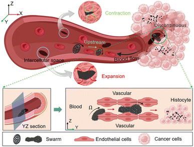 | ||
| Fig. 1 The illustration of upstream movement and peritumor blood vessel crossing of magnetic nanoparticle swarm. | ||
MNPs have gained increasing attention as drug-delivery vehicles in the applications of precision medicine,30 and may be used to enhance leakage of blood vessels around the tumor.31 In comparison to pre-fabricated microrobots, such as magnetic nano-crane,32 octopus,33 and fishes with serrated tails,34 MNPs offer the potential advantage of mass production and reduced costs.35 As carriers, they can overcome some of the limitations associated with traditional drug formulations by leveraging their unique design to modulate their biological distribution and pharmacokinetics within the organism.36,37 However, due to the tiny scale, individual MNPs may not effectively demonstrate their advantages in drug transporting and overcoming physiological barriers. To deal with these challenges, stable and dynamic swarms assembled by MNPs offer a compelling solution for targeted drug delivery and successful accumulation. When MNPs aggregate at high densities, the formed swarms exhibit excellent robustness and maneuverability through magnetic field programming.38,39 The ability to reconfigure these swarms enables rapid adaptation to complex environmental and task demands.
Inspired by the collective behavior of wild herring schools and the transvascular migration of leukocytes, we propose an innovative actuation strategy to assemble 200 nm diameter MNPs from a uniform and monodispersed state to a vortex-like swarm under the action of a specialized electromagnetic field. The swarm can maintain remarkable stability in high-speed blood flow of 1 mm s−1 without being scattered and can be actively navigated to the targeted location, then, effectively anchored by adjusting magnetic field parameters. The swarm exhibits exciting upstream movement ability under the impact of blood flow and tends to immigrate towards the vascular wall due to the transverse force generated by its rotation (around 10 Hz), which is the most important reason why our swarms can perform upstream motion actuated by only one external energy field, compared to the previous reported magnetic-ultrasound field.40 The low-speed layer and rolling friction of the vascular wall provide convenience for the precise navigation of the swarm in pulsatile flow. The experimental swarm can withstand a maximum flow velocity of 1 mm s−1, corresponding to the physical conditions of microcirculation, e.g. arterioles, capillaries and venules, which is also the location where leukocytes are most likely to undergo extravasation.
When the swarm is navigated to the designated location and docks, its high-speed rotation interacts with the vascular wall, providing a propulsive force toward the interior of the tumor. When the edge of the swarm contacts the discontinuous vascular gap, its rheology causes the swarm to actively adhere to the edge of the gap, generating effective friction for the overall advance of the swarm. Under the action of a rotating magnetic field, the swarm deforms and crawls in the restricted gap, promoting it to pass through the narrow intercellular gap and reach the tumor matrix. As shown in Fig. 1. It is worth noting that the swarm can be reconfigured, and when the magnetic field is turned off after completing tasks, the paramagnetic nanoparticles will immediately disperse and be washed away by blood flow or diffuse in the tumor interstitium. This reconstruction feature can greatly reduce the risk of vascular congestion. Our strategy simplifies the actuation device allowing multiple functions such as wall adherence, upstream motion, docking, and traversing the vessel wall under the action of electromagnetic fields only. Finally, we validated the ability of MNPs to induce cancer cell apoptosis using simple but effective photothermal therapy. Compare to previous work, this manuscript focuses on the ability of a vortex-like swarm to pass through a discontinuous vessel wall; with the swarm's rheological ability and attachment to the vessel wall, it can pass through narrow gaps smaller than its own size in a swarming pattern, which is not possible with rigid-body micro-rollers.41 This strategy is expected to a solid foundation for the large-scale tumor drug delivery in the future.
Results and discussion
Upstream motion control of magnetic nanoparticle swarm
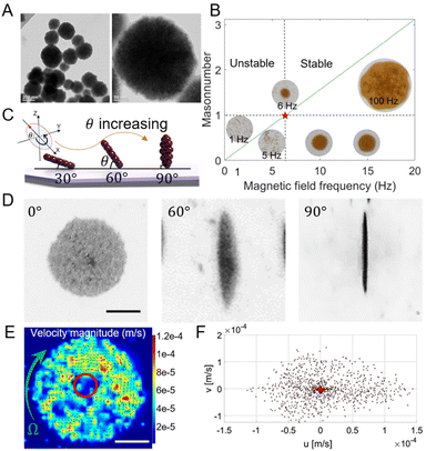
The magnetic nanoparticle swarm is assembled under the co-action of complex magnetic and flow fields, and the success of its assembly mainly depends on the ratio of magnetic force and fluid viscous force on nanoparticles. Here we used 200 nm-diameter Iron(II,III) oxide nanoparticles as experimental material (purchased from Bionano New Material Science, Taizhou, China), which is the largest diameter of nanoparticles for clinical applications, and it is also a primary FDA-approved inorganic nanoparticle for drug delivery in humans.42 The TEM images are shown in Fig. 2A. The MNPs are not regular spheres, with an average diameter of 200 nm. Before performing actuation experiments, 3 minutes of ultrasonic vibration is required to maintain uniform dispersion of nanoparticles.When exposed to the magnetic field, Fe3O4 nanoparticles can be magnetized and form a magnetization parallel to the long axis of the shape-anisotropy particles, which is also known as the easy axis.32,43,44 The magnetic dipole forces between nanoparticles will attract them to connect into chains and align along the magnetic field direction. When the uniform magnetic field rotates at a low frequency, particle chains tend to rotate with the magnetic field. Rotating chains can trigger local vortices and the most intense fluid velocities and pressures are generated near the very two edges of chains.13 When increasing the magnetic field frequency, particle chains will rotate faster along with the field, therefore producing stronger fluid vortices. The powerful vortex will attract surrounding chains to approach and collide with each other. When the magnetic field frequency is over a critical frequency (6 Hz in our experiments), chains in the phase lag condition will become extremely unstable and finally form vortex-like nanoparticle swarms.13,45,46 As shown in Fig. 2B.
The stability of magnetic nanoparticle chains mainly depends on the strength and frequency of the applied magnetic field. Here, we used the Mason number to describe the stability of particle chains, which is a dimensionless number and defined as the ratio of magnetic dipole force and fluid viscous force.13,47 As shown in the following equation:
 | (1) |
The vortex-like magnetic nanoparticle swarm is more active and robust than a chain-like swarm.45 Since the attitude of the vortex-like swarm is aligned with the rotating magnetic field, we can adjust the pitch angle (θ) and the yaw angle (φ) of the magnetic field to change the motion direction and the attitude of the swarm (see Fig. 2C). With the increases of the pitch angle of the magnetic field, the vortex-like swarm gradually “stands up”, so that the component parallels to the XY plane in the magnetic field vector giving it considerable surface rolling ability while maintaining a stable swarm. From the top view, the nanoparticle swarm switched from a circle to a spindle, when the magnetic field pitch angle reached 90°, the swarm appears to be a line, as shown in Fig. 2D. Varying pitch angle and the field strength is key to controlling the speed of swarms, the motion velocity of the swarm is overall positive correlation with these parameters within a certain range.48 The swarm velocity distribution was analyzed using Particle Image Velocimetry, as shown in Fig. 2E and Movie S1.† There is a low-speed area in the middle of the warm, which is circled in red, and the particle velocity in the area away from the center increases considerably. More than 90% of nanoparticles in the swarm have a velocity below 100 μm s−1 (see Fig. 2F).
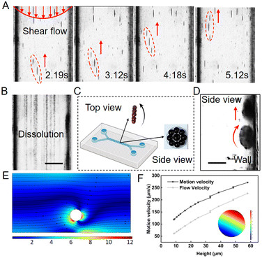
To deliver drugs through the circulatory system, nanoparticle carriers are required to keep robust and controllable. Here, a microfluidic chip fabricated by polydimethylsiloxane (PDMS) was used as a blood vessel to test the performance of nanoparticle swarm in the pulsatile fluid. The magnetic nanoparticle suspension with a concentration of 0.5 mg mL−1 was injected into the microfluidic chip using a syringe pump and kept the peak flow rate at nearly 1 mm s−1, which corresponds to the flow rate in small arteries and capillaries.49 When setting the magnetic field frequency at 100 Hz and pitch angle at 90°, scattered nanoparticles can be quickly assembled into vortex-like swarms. The swarms were inclined to roll upstream near the wall, which is the lowest flow rate layer in the vessel. The presence of the wall allows a microrobot to break the flow rate and pressure symmetry around itself in viscous fluid, which is helpful to transform rotational movement to translational movement, therefore inducing pure propulsion.50 Under the tilted rotating field, nanoparticle swarms can move against the pulsatile flow with an average velocity of 500 μm s−1. To cope with the shear force and drastic impact, swarms tended to perform lateral slippage while upstream, as shown in Fig. 3A.
When withdrawing the magnetic field, assembled swarms got scattered into nanoparticles, and washed away by the flow, as shown in Fig. 3B. The reconfigurable ability of vortex-like swarms can largely reduce the risk of thrombosis, making them have the potential of becoming a superior micro-roller in the medical field.51 From the top view and side view observation, the swarm is confirmed as a thin disk, with the diameter a = 30 ± 5 μm and the thickness t = 1.5 ± 0.15 μm, rolling upstream against the wall (see Fig. 3C and D).
Next, we established a dynamic model to describe the upstream movement of the vortex-like nanoparticle swarm. Due to the tiny scale of the swarm, its movement environment is in a low Reynolds number state, a swarm is subjected to a variety of forces, mainly including gravity FG, viscous drag force FD, rotational lateral force FRL, shear lift force FSL, wall-induced lift force FWL, and friction force FF.52–54 As shown below and see more detail in Fig. S3 and Movie S2.†
| FG = πa2tρPg | (2) |
 | (3) |
| FRL = 2πρFa2tω × (UP − UF) | (4) |
| FSL = 0.5πμa2(Up – Uf) | (5) |
| FWL = 2πμa(UP – UF) | (6) |
| FF = μFFN | (7) |
 | (8) |
| ω = 0.1f | (9) |
 | (10) |
Meanwhile, we collected the motion velocity and the maximum flow velocity around the swarm through simulation, as shown in Fig. 3F. With a decrease in height, which is also known as the lubrication gap, the motion velocity and the flow velocity decreased. However, the motion velocity of the swarm was always higher than the flow velocity, inducing the upstream movement.
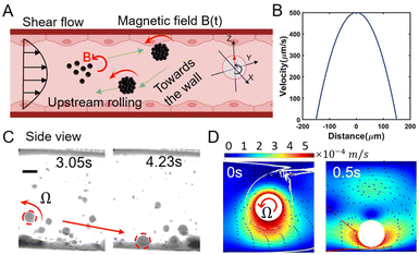
When the initial position of the assembled swarm is near the middle of the fluidic channel, the intense impact of the flow would drag swarms downstream. But based on the Magnus Effect, the rotating object in a shear flow can be subjected to two lateral forces: rotational lift force FRL generated by high-speed rotation, pointing to the wall, and shear lift force FSL generated by shear flow, pointing to the center of the channel.55,56 Saffman etc. prove that the FRL is smaller than the FSL unless the object rotates much faster than shear,57 which is consistent with the condition for upstream movement.
After theoretical calculation, the rotational lift force (FRL = 5.819 × 10⁻¹² N) is nearly an order of magnitude greater than the shear lift force (FSL = 4.103 × 10⁻¹³ N) in this manuscript. With the combination of gravity and rotational lift force, the nanoparticle swarm can be dragged to the wall (see Fig. 4A). Theoretically, the flow rate distribution in blood vessels is parabolic along the cross-section, as shown in Fig. 4B. Next, a microfluidic chip with a diameter of 300 μm and a peak flow velocity of 500 μm s−1 in it was used to verify the tendency of rotational lift force towards the wall. Fig. 4C demonstrates a side view of the swarm rotating towards the wall under the action of a high-frequency rotating magnetic field. The low flow velocity and asymmetrical structure provided by the wall position facilitate the realization of upstream movement. Fig. 4D indicates the motion simulation of this process. When subjected to a 100 Hz-frequency rotating field, the simulated rigid swarm produces a transverse force on the order of 10−12 N, and drags the swarm to the vessel surface while generating vortices on the top. Due to the rotational lift force, this actuation strategy can complete tasks of both upstream motion and wall-toward motion relying only on an electromagnetic field as the power source.
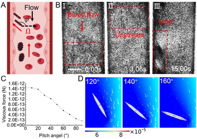
Next, we tested the upstream and targeted docking ability of the swarm in the blood flow, and the schematic graph is shown in Fig. 5A. To better simulate the circulatory system, some Six-fold diluted freshly drawn mouse blood was injected into the microfluidic chip with a peek flow velocity of 500 μm s−1. As shown in Fig. 5B and Movie S3,† vortex-like swarms, which are circled by a red dashed box, can actively move against the flowing blood. According to our previous study,45 even in more complex simulated 3D vessels, the vortex-like swarm can still freely travel between branches according to a preset trajectory. When the targeted area is confirmed, by changing the yaw angle (φ) of the magnetic field to 135°, assembled swarms can perform upstream motion by tilting in the specified direction. As long as swarms reached the wall, they would roll against the inner surface of the blood vessel, thus withstanding the friction and counterforce from the surface. At this moment, the Y-axis component of the motion velocity is used to counteract the flow field action and the X-axis component can provide a potential propulsion force to thread through the blood vessel. Overall, the increase in the swarm pitch angle can effectively reduce the viscous resistance it is subjected to, see Fig. 5(C). When the pitch angle is set to a maximum value of 90°, increasing the yaw angle of the swarm, its Y-axis propulsive force decreases, and it is gradually insufficient to resist blood flow and undergoes downstream movement, as shown in Fig. 5(D).
In vitro simulation of magnetic nanoparticle swarm crossing peritumor vessel wall
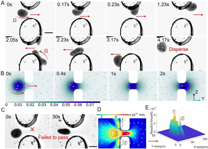
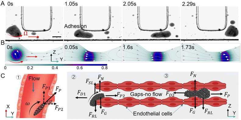
To date, when using nanoparticles as carriers for targeted drug delivery in cancer therapy, the accumulation of drugs in tumor tissues is often achieved through the enhanced permeability and retention (EPR) effect. However, the process of nanomedicine entering the tumor through the vascular wall is mainly dependent on fluid permeation and exchange between the tumor stroma and surrounding blood vessels, which is a slow and passive process.35 This study proposes a novel approach that utilizes the magnetic nanoparticle swarm to actively propel through narrow and discontinuous gaps in the blood vessel wall. To simulate the tumor microenvironment with non-continuous connections in vitro, a custom-made microfluidic chip was developed to perform penetration experiments on vascular endothelial intercellular gaps. Then microfluidic chip provides a gap of 15 μm, which is consistent with the physiological characteristic of neovascularization around the tumor.28,29,58 As shown in Fig. 6A, the protrusions located at the top and bottom are interpreted as endothelial cells with certain gaps. When the rotating magnetic field is set to a frequency of 100 Hz and a pitch angle of 90°, the nanoparticle swarm in a disc shape generates X-directional propulsive force through high-speed rotation, which pushes the swarm towards the blood vessel wall and contacts the edge of the gap. Due to the rheology of the dynamically assembled swarm, it can migrate as a huge complete structure through the wall composed of narrow slits and endothelial cells. When the swarm of nanoparticles contacts the surface of the simulated endothelial cell, it exhibits a movement pattern similar to worm-like crawling, quickly deforming and crawling by adhering to the channel surface, thus smoothly passing through the narrow gap. Fig. 6A respectively show the process of swarm moving back and forth from both sides of the gap. This movement mode actively breaks the movement dilemma of micro-rollers in a restricted environment through deformation and crawling.The process of the swarm passing through the gap was also simulated by Comsol, reflecting the deformation process of the high-speed rotating swarm and the disturbance to the surrounding fluid, as shown in Fig. 6B. In a narrow-constrained channel, the efficiency of the rigid micro-swimmer's motion decreases dramatically due to the increased interaction of the out-of-plane rotational flow generated during rotation with the wall, the strong rotational flow constrains its motion, and the micro-swimmer needs to create a smaller rotational flow field in order to achieve controllable actuation in a constrained environment. When the swarm attempts to pass through the middle of the slit in an unattached manner, its high-speed rotation generates a strong out-of-plane rotational flow at the wall, as shown in Fig. 6(D). The part circled in the figure is the region of high reaction force generated by the rotational flow field, with a peak value of up to 4 × 10⁻⁷ N, see Fig. 6(E), which is far more than the forward driving force that the swarm can provide (about 10−11 N). Eventually the swarm cannot get through the slit, as shown in the Fig. 6(C), with the same magnetic field configuration, the swarm was unable to pass through the slit for 30s. Furthermore, we verified that the magnetic nanoparticle swarm still can actively deform and propel in a confined channel with a height of 10 μm and a length of 40 μm. The experimental results and simulations are shown in Fig. 7(A), (B) and Movie S4.† This study provides a promising approach for improving the efficiency of tumor-targeted drug delivery. The behavior of a vortex-like swarm as it crosses the vascular gap can be divided into three stages: docking, attaching at the edge of the gap, and crawling across the gap, see Fig. 7(C). At the first stage, the yaw angle (φ) of the swarm is set to 30°∼60° (right stop) or 120°∼150° (left stop), at which point the rotating swarm provides a propulsive force FP along the forward direction.59 The Y-axis component of this propulsive force FP2 is used for sustained docking and adhesion to the vessel wall gap, and the component along the X-axis (FP1) is used to counteract the fluid shock:
 | (11) |
FP1 = Fpsin![[thin space (1/6-em)]](https://www.rsc.org/images/entities/char_2009.gif) φ φ | (12) |
FP = Fpcos![[thin space (1/6-em)]](https://www.rsc.org/images/entities/char_2009.gif) φ φ | (13) |
At the second stage, the very edge of the swarm starts to touch the edge of the gap, and it should maintain the wall-adhesion state for propulsion. We can approximate that one side of the swarm is in the blood flow and the other side is in the gap, at this time, the swarm is subjected to fluid drag, lift, gravity, etc., but due to the rheological and deformable properties of the swarm, the out-of-plane rotational flow it generates is slight, see Fig. 7(B), and the environment is dominated by an advective flow field, which would help the swarm to move in the narrow gap.
 | (14) |
At the third stage, the swarm totally moves in the gap, and there is no shear lift force. In a low Reynolds number environment, the swarm is considered to be in an overdamped state, so it can be approximated as being in force equilibrium, and the mechanical equations can be listed into the following:
 | (15) |
Targeted apoptosis of cancer cells induced by magnetic nanoparticle swarm
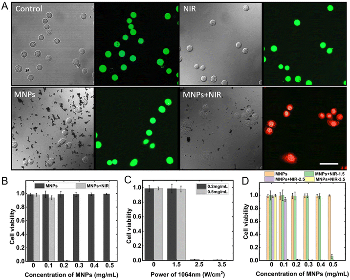
After passing through the blood vessel and dispersing around the tumor tissues, MNPs are required to perform the task of cancer cell apoptosis. Photothermal therapy utilizes the heat generated from photothermal materials under the NIR irradiation at a specific wavelength to kill cancer cells.60 The NIR with a wavelength of 1064 nm is introduced to perform the targeted cancer cell apoptosis, which enables greater tissue penetration depth and high-resolution imaging compared with the commonly used 808 nm-wavelength NIR.61 Here breast cancer cells cultured under a sterile environment with 37 °C and 25% CO2 were used to test the targeted cancer apoptosis ability. The experimental cells were divided into four groups: control group without treatment, intervention group with NIR irradiation, intervention group with MNPs, intervention group with MNPs and NIR irradiation. After treatments, the culture medium and nanoparticles were carefully removed from the cell colonies, and the PBS solution was introduced to wash the cancer cells twice. Next, the co-stain with Calcein-AM/PI is used to distinguish alive and dead cells. The representative staining results are shown in Fig. 8A. The blank control group, the intervention groups with NIR radiation for 3 minutes, and the intervention groups with MNPs showed green fluorescence under the confocal scanning laser microscope, indicating that there were few dead cells available in a normal growth state, NIR irradiation, and MNPs added conditions.When applied the 1064 nm NIR irradiation with a power density of 2.5 W cm−2 for 3 minutes, the groups with MNPs concentration of 0, 0.1, 0.2, 0.3, 0.4, and 0.5 mg mL−1, without NIR irradiation, had a cell viability of 98.52%, 98.62%, 98.74%, 98.80%, 98.78%, 99.39%, respectively. It proves that MNPs cause little damage to cancer cells. However, when combined above the gradient concentration of MNPs and NIR, the cell viability exhibited a intense decrease, which was 97.96%, 93.60%, 1.24%, 0.47%, 0.43%, and 0.35%, as shown in Fig. 8B. Adding MNPs at a concentration of 0.5 mg mL−1 to the cancer cells and irradiating with NIR laser at power densities of 1.5, 2.5, and 3.5 W cm−2 for 3 minutes, the cell viability induced was 6.25%, 0.35%, 0.05%, respectively (see Fig. 8C). While under the same laser irradiation conditions, the cell viability caused by MPNs with a concentration of 0.2 mg mL−1 was 98.61%, 1.24%, and 0.88% (see Fig. 8D). The results suggest that the photothermal effect of MNPs is strongly dependent on laser power density and MNPs concentration. Relevant research has indicated that blood flow within the tumor region tends to be sluggish, with a blood flow rate of only 1%–15% compared to normal tissues. This limited blood flow makes it difficult to dissipate heat, leading to heat accumulation. On the other hand, heat causes blood vessels in normal tissues to dilate, thereby accelerating blood flow and heat dissipation. As a result, the temperature difference between the tumor area and adjacent normal tissues can reach up to 5–10 °C. Tumor cells can be effectively induced to undergo apoptosis at temperatures ranging from 42.5 °C to 43 °C, while normal cells remain unharmed at temperatures above 44 °C. Therefore, precise control of the heating temperature can achieve effective tumor area destruction without damaging normal tissues.62,63
Conclusions
In general, the swarm of self-assembled magnetic nanoparticle swarm presents numerous advantages over pre-fabricated microrobots. The availability of commercially available MNPs reduces the difficulty of sophisticated microrobot fabrication and mass production. The deformable swarm, assembled by magnetic dipole–dipole interaction, the reconfigurability of swarms can effectively reduce the risk of thrombosis and vascular obstruction. Furthermore, the presence of the swarm enhances the magnetic response and imaging contrast of drug carriers, facilitating navigation and tracking of targeted drug delivery in the future.6,64Under the guidance of a specific magnetic field, the vortex-like magnetic nanoparticle swarm can actively approach the simulated blood vessel and exploit the advantages of the low-speed boundary layer. It also breaks the fluid symmetry of rotational motion under a viscous fluid and generates a strong propulsive force (FPMAX = 4 × 10⁻⁷ N, see Fig. 6E). The ability to achieve precise upstream motion solely by an electromagnetic field is an exciting prospect. Moreover, the swarm can actively brake and park upon reaching the target area, then, crawl through narrow gaps. This promising large-scale targeted drug delivery strategy is noteworthy.
We believe that the strategy we proposed can eventually be translated into animal models. Although biological tissues produce little attenuation effects on magnetic fields, we still need to consider the complexity of the real circulatory system. We conducted In vitro experiments on a microfluidic chip with a diameter of 300 μm and an average flow velocity of 500 μm s−1, corresponding to physiological conditions in small veins or capillaries. By raising the magnetic field strength and frequency, the theoretical upper limit of the swarm's upstream motion speed can reach 1 mm s−1, which is sufficient to adapt to most environments in smallest arterioles, capillaries, and small veins. We believe that the swarm can reach the target tumor location stably, but the feasibility of the swarm penetrating endothelial cell gaps in vivo needs to be verified by more precise in vitro models. Under the current experimental conditions, we found that the swarm can induce crawling by adhering to the gap edge, thus passing through the preset narrow gap. Thanks to the deformability of the swarm, it also exhibits great mobility in a 10 μm-wide channel, which enhances our confidence in the swarm's application in large-scale targeted drug delivery. However, limited by the penetration depth of NIR laser in tissues, the photothermal therapy used in this manuscript is only suitable for the treatment of shallow disease. In the future, we hope to introduce advanced imaging methods such as photoacoustic imaging,65 magnetic particle imaging,66 and magnetic resonance imaging67 to accurately track and actuate swarms in vivo, guiding them to accumulate in the correct position. In addition, the advantages of the swarm's large drug-carrying capacity should be well developed, exploring more strategies to induce tumor apoptosis to improve cancer treatment.
Experimental
Magnetic navigation system
The custom built magnetic navigation system used in this manuscript consists of 6 electromagnetic coils, each 2 of which are connected in series. The 3 pairs of coils are arranged orthogonally according to the Cartesian coordinate system. Similar to the Helmholtz coil, the magnetic navigation system can generate a uniform magnetic field with a uniformity of over 97% in a 2 cm-diameter working place. The system also carries a data acquisition (NI-6289), three drivers (DZRALTE-040L080), a CCD camera (HT-2000CN), and a feedback control module based on visual recognition, as shown in Fig S1.†Fabrication of microfluidic chips
The fabrication of microfluidic chips mainly includes 5 steps. First, the mold for microfluidic chips is produced by a high-precision 3D printer using photosensitive resin (NanoArch P140, BMFPrecision, China). Next, the Sylgard 184 silicone elastomer is mixed with a corresponding curving agent at a mass ratio of 10![[thin space (1/6-em)]](https://www.rsc.org/images/entities/char_2009.gif) :
:![[thin space (1/6-em)]](https://www.rsc.org/images/entities/char_2009.gif) 1 to compose the PDMS (Dow Corning, Midland, USA), and keep the mixture in the refrigerator at −20 °C after mixing them thoroughly. Then, the surface of the printed mold is processed with WD-40 to ensure it is lubricated and hydrophobic. After the surface of the mold dries, the PDMS mixture is poured into the bottom-fixed mold vacuumed for 1 hour to eliminate bubbles, and then put in a 6 °C- electric heating blast drying oven to complete curving. Finally, the curving agent layer is separated from the mold and completes the surface bonding with the glass under the plasma cleaning machine.
1 to compose the PDMS (Dow Corning, Midland, USA), and keep the mixture in the refrigerator at −20 °C after mixing them thoroughly. Then, the surface of the printed mold is processed with WD-40 to ensure it is lubricated and hydrophobic. After the surface of the mold dries, the PDMS mixture is poured into the bottom-fixed mold vacuumed for 1 hour to eliminate bubbles, and then put in a 6 °C- electric heating blast drying oven to complete curving. Finally, the curving agent layer is separated from the mold and completes the surface bonding with the glass under the plasma cleaning machine.
Motion control of magnetic nanoparticle swarm
The magnetic nanoparticle swarm is driven by a skewed uniform rotating magnetic field, and the posture of the swarm is consistent with that of the magnetic field. When performing actuation experiments in a static fluid, a 3 μL nanoparticle suspension drop is placed on a clean-surface glass slide. The swarm can be formed under the c magnetic and flow fields’ collective effort The motion control of the magnetic nanoparticle swarm is performed in a microfluidic chip. The magnetic nanoparticle suspension with a concentration of 0.5 mg mL−1 is injected into the microfluidic channel at a flow velocity of 500 μm s−1. Then by adjusting the parameters of the magnetic field, swarms can achieve multiple motion modes, such as upstream motion, targeted stopping, and crossing the confined channel.Targeted cancer cell apoptosis and cell staining in vitro
The 4T1 cell lines used in this manuscript were purchased from the National Infrastructure of Cell Line Resource and propagated in incubation at 37 °C with 25% carbon dioxide. When conducting targeted cancer cell apoptosis in vitro, the magnetic nanoparticle swarm can be formed and navigated to the predetermined location. After 3 minutes of NIR irritation with a wavelength of 1064 nm and power density of 2.5 W cm−2, the heat generated by the photothermal effect of magnetic nanoparticle swarms can kill cancer cells. When staining cancer cells after the targeted apoptosis experiments, the assay buffer, Calcein-AM, PI (Solarbio Life Sciences, Beijing, China), and purified water are mixed at a volume ratio of 1![[thin space (1/6-em)]](https://www.rsc.org/images/entities/char_2009.gif) :
:![[thin space (1/6-em)]](https://www.rsc.org/images/entities/char_2009.gif) 1
1![[thin space (1/6-em)]](https://www.rsc.org/images/entities/char_2009.gif) :
:![[thin space (1/6-em)]](https://www.rsc.org/images/entities/char_2009.gif) 1
1![[thin space (1/6-em)]](https://www.rsc.org/images/entities/char_2009.gif) :
:![[thin space (1/6-em)]](https://www.rsc.org/images/entities/char_2009.gif) 7 to obtain the staining solution. Then, carefully remove the culture medium and MNPs from the Petri dish. Add dye to the dish and fully cover the cells, stain under dark conditions for 10 minutes, and transfer it to the confocal microscope to observe the viability of cells.
7 to obtain the staining solution. Then, carefully remove the culture medium and MNPs from the Petri dish. Add dye to the dish and fully cover the cells, stain under dark conditions for 10 minutes, and transfer it to the confocal microscope to observe the viability of cells.
Author contributions
L. W. completed all experiments, analyzed the data, and wrote the manuscript. C. G. finished the finite element analysis. H. S. assisted in the cell staining. L. F. supervised the project. All authors participated in the review of this manuscript.Conflicts of interest
There are no conflicts to declare.Acknowledgements
This work was supported by the National Key R&D Program of China (Grant No. 2022YFF1502000) and the Beijing Municipal Fund for Distinguished Young Scholars (Grand No. JQ22022).References
- P. Cabanach, A. Pena-Francesch, D. Sheehan, U. Bozuyuk, O. Yasa, S. Borros and M. Sitti, Adv. Mater., 2020, 32, 1–11 Search PubMed
.
- A. Aghakhani, O. Yasa, P. Wrede and M. Sitti, Proc. Natl. Acad. Sci. U. S. A., 2020, 117, 3469–3477 CrossRef CAS PubMed
.
- M. B. Akolpoglu, N. O. Dogan, U. Bozuyuk, H. Ceylan, S. Kizilel and M. Sitti, Adv. Sci., 2020, 7, 1–10 Search PubMed
.
- H. Zhang, Z. Li, C. Gao, X. Fan, Y. Pang, T. Li, Z. Wu, H. Xie and Q. He, Sci. Robot., 2021, 6, 1–16 Search PubMed
.
- L. Wang, Y. Shi, J. Jiang, C. Li, H. Zhang, X. Zhang, T. Jiang, L. Wang, Y. Wang and L. Feng, Small, 2022, 18, 1–39 CAS
.
- J. Yu, D. Jin, K. F. Chan, Q. Wang, K. Yuan and L. Zhang, Nat. Commun., 2019, 10, 1–12 CrossRef PubMed
.
- Z. Wu, J. Troll, H. Jeong, Q. Wei, M. Stang, F. Ziemssen, Z. Wang, M. Dong, S. Schnichels, T. Qiu and P. Fischer, Sci. Adv., 2018, 4, 1–11 Search PubMed
.
- D. Schamel, A. G. Mark, J. G. Gibbs, C. Miksch, K. I. Morozov, A. M. Leshansky and P. Fischer, ACS Nano, 2014, 8, 8794–8801 CrossRef CAS PubMed
.
- C. Huang, Z. Lai, X. Wu and T. Xu, Cyborg Bionic Syst., 2022, 2022, 0004 CrossRef PubMed
.
- E. Perez-Guagnelli, J. Jones and D. D. Damian, Cyborg Bionic Syst., 2022, 2022, 9786864 Search PubMed
.
- X. Yang, W. Shang, H. Lu, Y. Liu, L. Yang, R. Tan, X. Wu and Y. Shen, Sci. Robot., 2020, 5, 1–13 Search PubMed
.
- M. Sun, K. F. Chan, Z. Zhang, L. Wang, Q. Wang, S. Yang, S. M. Chan, P. Wai, Y. Chiu, J. Jao, Y. Sung and L. Zhang, Adv. Mater., 2022, 34, 1–29 Search PubMed
.
- L. Wang, H. Gao, H. Sun, Y. Ji, L. Song, L. Jia, C. Wang, C. Li, D. Zhang, Y. Xu, H. Chen and L. Feng, Research, 2023, 6, 1–17 Search PubMed
.
- J. Zhang, Q. Fang, P. Xiang, D. Sun, Y. Xue, R. Jin, K. Qiu, R. Xiong, Y. Wang and H. Lu, Cyborg Bionic Syst., 2022, 2022, 9754697 Search PubMed
.
- L. Soler, C. Martínez-Cisneros, A. Swiersy, S. Sánchez and O. G. Schmidt, Lab Chip, 2013, 13, 4299–4303 RSC
.
- S. J. Black, D. P. Lunn, C. Yin, M. Hwang, S. D. Lenz and J. K. Belknap, Vet. Immunol. Immunopathol., 2006, 109, 161–166 CrossRef CAS PubMed
.
- J. L. Mehta and N. V. K. Pothineni, Hypertension, 2016, 68, 27–29 CrossRef CAS PubMed
.
- Y. Alapan, Y. Matsuyama, J. A. Little and U. A. Gurkan, Technology, 2016, 04, 71–79 CrossRef CAS PubMed
.
- X. Cao, E. Moeendarbary, P. Isermann, P. M. Davidson, X. Wang, M. B. Chen, A. K. Burkart, J. Lammerding, R. D. Kamm and V. B. Shenoy, Biophys. J., 2016, 111, 1541–1552 CrossRef CAS PubMed
.
- T. Gwisai, N. Mirkhani, M. G. Christiansen, T. T. Nguyen, V. Ling and S. Schuerle, Sci. Robot., 2022, 7(71), 1–16 Search PubMed
.
- R. Szulcek, C. M. L. Beckers, J. Hodzic, J. DeWit, Z. Chen, T. Grob, R. J. P. Musters, R. D. Minshall, V. W. M. Van Hinsbergh and G. P. Van Nieuw Amerongen, Cardiovasc. Res., 2013, 99, 471–482 CrossRef CAS PubMed
.
- J. Escribano, M. B. Chen, E. Moeendarbary, X. Cao, V. Shenoy, J. M. Garcia-Aznar, R. D. Kamm and F. Spill, PLoS Comput. Biol., 2019, 15, 1–21 CrossRef PubMed
.
- S. Sindhwani, A. M. Syed, J. Ngai, B. R. Kingston, L. Maiorino, J. Rothschild, P. MacMillan, Y. Zhang, N. U. Rajesh, T. Hoang, J. L. Y. Wu, S. Wilhelm, A. Zilman, S. Gadde, A. Sulaiman, B. Ouyang, Z. Lin, L. Wang, M. Egeblad and W. C. W. Chan, Nat. Mater., 2020, 19, 566–575 CrossRef CAS PubMed
.
- M. Bevilacqua, M. Barrella, R. Toscano and A. Evangelisti, IFMBE Proc., 2007, 16, 932–935 Search PubMed
.
- S. Willhelm, A. J. Tavares, Q. Dai, S. Ohta, J. Audet, H. F. Dvorak and W. C. W. Chan, Nat. Rev. Mater., 2016, 1, 16014 CrossRef
.
- P. Koumoutsakos, I. Pivkin and F. Milde, Annu. Rev. Fluid Mech., 2013, 45, 325–355 CrossRef
.
- L. Claesson-Welsh, E. Dejana and D. M. McDonald, Trends Mol. Med., 2021, 27, 314–331 CrossRef CAS PubMed
.
- H. Hashizume, P. Baluk, S. Morikawa, J. W. McLean, G. Thurston, S. Roberge, R. K. Jain and D. M. McDonald, Am. J. Pathol., 2000, 156, 1363–1380 CrossRef CAS PubMed
.
- Y. Matsumoto, J. W. Nichols, K. Toh, T. Nomoto, H. Cabral, Y. Miura, R. J. Christie, N. Yamada, T. Ogura, M. R. Kano, Y. Matsumura, N. Nishiyama, T. Yamasoba, Y. H. Bae and K. Kataoka, Nat. Nanotechnol., 2016, 11, 533–538 CrossRef CAS PubMed
.
- M. I. Setyawati, C. Y. Tay, D. Docter, R. H. Stauber and D. T. Leong, Chem. Soc. Rev., 2015, 44, 8174–8199 RSC
.
- M. I. Setyawati, C. Y. Tay, S. L. Chia, S. L. Goh, W. Fang, M. J. Neo, H. C. Chong, S. M. Tan, S. C. J. Loo, K. W. Ng, J. P. Xie, C. N. Ong, N. S. Tan and D. T. Leong, Nat. Commun., 2013, 4, 1–12 Search PubMed
.
- J. Cui, T. Y. Huang, Z. Luo, P. Testa, H. Gu, X. Z. Chen, B. J. Nelson and L. J. Heyderman, Nature, 2019, 575, 164–168 CrossRef CAS PubMed
.
- Y. Pan, L. H. Lee, Z. Yang, S. U. Hassan and H. C. Shum, Nanoscale, 2021, 13, 18967–18976 RSC
.
- D. Li, Y. Liu, Y. Yang and Y. Shen, Nanoscale, 2018, 10, 19673–19677 RSC
.
- S. Schuerle, A. P. Soleimany, T. Yeh, G. M. Anand, M. Häberli, H. E. Fleming, N. Mirkhani, F. Qiu, S. Hauert, X. Wang, B. J. Nelson and S. N. Bhatia, Sci. Adv., 2019, 5, 1–11 Search PubMed
.
- R. Tong and R. Langer, Cancer J., 2015, 21, 314–321 CrossRef CAS PubMed
.
- J. Shi, P. W. Kantoff, R. Wooster and O. C. Farokhzad, Nat. Rev. Cancer, 2017, 17, 20–37 CrossRef CAS PubMed
.
- M. Sun, X. Fan, C. Tian, M. Yang, L. Sun and H. Xie, Adv. Funct. Mater., 2021, 31, 1–11 Search PubMed
.
- H. Xie, M. Sun, X. Fan, Z. Lin, W. Chen, L. Wang, L. Dong and Q. He, Sci. Robot., 2019, 4, 1–15 Search PubMed
.
- D. Ahmed, A. Sukhov, D. Hauri, D. Rodrigue, G. Maranta, J. Harting and B. J. Nelson, Nat. Mach. Intell., 2021, 3, 116–124 CrossRef PubMed
.
- U. Bozuyuk, A. Aghakhani, Y. Alapan, M. Yunusa, P. Wrede and M. Sitti, Nat. Commun., 2022, 13, 1–12 Search PubMed
.
- C. Dhand, M. P. Prabhakaran, R. W. Beuerman, R. Lakshminarayanan, N. Dwivedi and S. Ramakrishna, RSC Adv., 2014, 4, 32673–32689 RSC
.
- U. Bozuyuk, Y. Alapan, A. Aghakhani, M. Yunusa and M. Sitti, Proc. Natl. Acad. Sci. U. S. A., 2021, 118, 1–10 CrossRef PubMed
.
- S. Zhang, X. Hu, M. Li, U. Bozuyuk, R. Zhang, E. Suadiye, J. Han, F. Wang, P. Onck and M. Sitti, Sci. Adv., 2023, 9, eadf9462 CrossRef CAS PubMed
.
- L. Wang, L. Song, H. Sun, Y. Ji, Y. Dai and L. Feng, IEEE Robot. Autom. Lett., 2022, 7, 3578–3583 Search PubMed
.
- J. Yu, L. Yang and L. Zhang, Int. J. Robot. Res., 2018, 37, 912–930 CrossRef
.
- S. Krishnamurthy, A. Yadav, P. E. Phelan, R. Calhoun, A. K. Vuppu, A. A. Garcia and M. A. Hayes, Microfluid. Nanofluid., 2008, 5, 33–41 CrossRef CAS
.
- L. Wang, L. Song, L. Jia, H. Sun, Y. Ji, Y. Dai and L. Feng, in 2021 WRC Symposium on Advanced Robotics and Automation, WRC SARA 2021, IEEE, 2021, pp. 13–17.
- B. J. Nelson, I. K. Kaliakatsos and J. J. Abbott, Annu. Rev. Biomed. Eng., 2010, 12, 55–85 CrossRef CAS PubMed
.
- E. M. Purcell, Am. J. Phys., 1977, 7, 541–559 Search PubMed
.
- M. Sun, K. F. Chan, Z. Zhang, L. Wang, Q. Wang, S. Yang, S. M. Chan, P. Wai, Y. Chiu, J. Jao, Y. Sung and L. Zhang, Adv. Mater., 2022, 34, 1–14 Search PubMed
.
- H. J. Keh and L. R. Wang, J. Fluids Struct., 2008, 24, 651–663 CrossRef
.
- Y. Damianou and G. C. Georgiou, J. Non-Newton. Fluid Mech., 2014, 214, 88–105 CrossRef CAS
.
- F. P. Bretherton, J. Fluid Mech., 1962, 12, 591–613 CrossRef
.
- R. D. Field, P. N. Anandakumaran and S. K. Sia, Appl. Phys. Rev., 2019, 6(4), 1–21 Search PubMed
.
- L. M. Milne-Thomson, Q. J. R. Meteorol. Soc., 1960, 86, 433 Search PubMed.
- P. G. Saffman, J. Fluid Mech., 1965, 22, 385–400 CrossRef
.
- D. Klein, Front. Oncol., 2018, 8, 1–10 CrossRef PubMed
.
- Y. Alapan, U. Bozuyuk, P. Erkoc, A. C. Karacakol and M. Sitti, Sci. Robot., 2020, 5, 1–11 Search PubMed
.
- H. Peng, J. Tang, R. Zheng, G. Guo, A. Dong, Y. Wang and W. Yang, Adv. Healthcare Mater., 2017, 6(7), 1–12 Search PubMed
.
- W. Zhang, W. Deng, H. Zhang, X. Sun, T. Huang, W. Wang, P. Sun, Q. Fan and W. Huang, Biomaterials, 2020, 243, 119934 CrossRef CAS PubMed
.
- P. Vaupel, Semin. Radiat. Oncol., 2004, 14, 198–206 CrossRef PubMed
.
- S. K. Jones, J. G. Winter and B. N. Gray, Int. J. Hyperthmia, 2002, 18, 117–128 CrossRef CAS PubMed
.
- Q. Wang, K. F. Chan, K. Schweizer, X. Du, D. Jin, S. C. H. Yu, B. J. Nelson and L. Zhang, Sci. Adv., 2021, 7, 1–13 Search PubMed
.
- H. Chen and G. Diebold, Science, 1995, 270, 963–966 CrossRef CAS
.
- G. Song, M. Chen, Y. Zhang, L. Cui, H. Qu, X. Zheng, M. Wintermark, Z. Liu and J. Rao, Nano Lett., 2018, 18, 182–189 CrossRef CAS PubMed
.
- N. V. Dhole and V. V. Dixit, Review of brain tumor detection from MRI images with hybrid approaches, Multimed. Tools Appl., 2022, 81, 10189–10220 CrossRef
.
Footnote |
| † Electronic supplementary information (ESI) available. See DOI: https://doi.org/10.1039/d3nr02610h |
| This journal is © The Royal Society of Chemistry 2023 |

