 Open Access Article
Electrochemical CO2 conversion technologies: state-of-the-art and future perspectives†
Remko J.
Detz
 *a,
Claire J.
Ferchaud
b,
Arie J.
Kalkman
c,
Jasmin
Kemper
d,
Carlos
Sánchez-Martínez
 c,
Marija
Saric
b and
Manoj V.
Shinde
b
aEnergy Transition Studies (ETS), Netherlands Organization for Applied Scientific Research (TNO), Radarweg 60, 1043 NT Amsterdam, The Netherlands. E-mail: remko.detz@tno.nl
bSustainable Technologies for Industrial Processes (STIP), Netherlands Organization for Applied Scientific Research (TNO), P.O. Box 1, 1755 ZG Petten, The Netherlands
cSustainable Process and Energy Systems (SPES), Netherlands Organization for Applied Scientific Research (TNO), P.O. Box 6012, 2600 JA Delft, The Netherlands
dIEA Greenhouse Gas R&D Programme, Pure Offices, Cheltenham Office Park, Hatherley Lane, Cheltenham, GLOS GL51 6SH, UK
First published on 25th October 2023
Abstract
Electrochemical reduction of CO2 to produce chemicals or fuels may contribute to the zero-emission goal of the chemical industry. Here, we report the state-of-the-art and future perspective of electrochemical CO2 conversion processes to produce CO, syngas, formic acid and ethylene. We selected and explored six routes: low-temperature CO production, low-temperature formic acid production, low-temperature ethylene production, high-temperature CO production, high-temperature syngas production, and a tandem approach to produce ethylene. For these routes, we describe the current level of development, performance indicators, and costs. The state-of-the-art of the chlor-alkali process is included as an example of a commercially applied electrochemical process. We calculate the economic performance of the various pathways in terms of levelized production costs and we use a learning curve method to project costs up to 2050. The greenhouse gas performance for all routes is determined and compared to the current reference of production from fossil-based resources. We conclude that high-temperature solid-oxide electrolysis to produce CO and syngas is the most developed and closest to reaching break-even levelized production cost in comparison to the fossil reference. Low-temperature electrolysis processes are at a lower technology readiness level and still need a substantial reduction in investment costs and improvements in process efficiency to achieve break-even with incumbent technology. The most promising of the low-temperature processes is formic acid production. Electrochemical production of formic acid, CO, and syngas results or can soon result in substantial GHG savings compared to their fossil-based alternatives. The extent to which savings can be achieved depends merely on the carbon intensity of the local power grid, or more generally, the supplied electricity. Electrochemical CO2 conversion to produce ethylene would require a very low emission factor of electricity (<50 gCO2 per kW h) to be competitive with current production methods and is therefore not likely to contribute significantly to the zero-emission goal of the petrochemical industry in the foreseeable future. Research gaps are identified at various levels: improvement of the performance of the various components, such as catalysts and electrodes, and of purification of feedstock and product streams. Pilot and demonstration projects of the entire value chain from the CO2 stream to the final product are needed to more accurately determine the performance, total investment costs, and operating and maintenance costs in an industrial environment.
1 Introduction
The use of fossil resources provides the world with highly concentrated forms of energy, but additionally with an abundance of carbon. Due to fuel combustion and waste incineration, a substantial share of this carbon is emitted to the atmosphere as carbon dioxide (CO2). Next to these undesirable CO2 emissions, many materials that are used in society, for example, bitumen, lubricants, plastics, and solvents, contain carbon as the main element. A vital climate change mitigation option encompasses the reduction of greenhouse gas (GHG) emissions of which fossil CO2 emissions account for roughly 70%.1 Various technologies to provide renewable energy, such as solar photovoltaics and wind turbines, are currently being deployed to avoid and replace the use of fossil fuels. Abandoning the use of fossil resources will eventually also reduce the availability of carbon as a feedstock to produce fuels, chemicals, building materials, and polymers. To find alternatives to fossil carbon, the chemical industry is already exploring various pathways to use circular flows of carbon, originating from either biogenic or atmospheric sources, or waste streams.2Carbon capture and utilization (CCU) technologies show promise for providing valuable, cost-competitive products to the economy while simultaneously mitigating CO2 emissions and climate change. Increased electrification and the increase of carbon-free, intermittent electricity have attracted global interest towards flexible CCU systems driven by electrical power. Electrochemical systems use electrons to reduce, for instance, CO2 into a multitude of products. This variety of products mirrors the diversity of electrochemical systems under development. For example, proton exchange membrane (PEM) electrolysers function under (near) ambient conditions, while solid-oxide systems can operate at temperatures above 700 °C. Unfortunately, existing CO2 conversion processes are energy-intensive and expensive. R&D efforts typically focus on improving the energy efficiency and selectivity of laboratory-scale demonstrations. More information is needed to understand the technical and economic hurdles that unique reactor systems may face when scaling from laboratory and bench scale projects to demonstration and pilot scale applications.
In this study, we review the use of CO2 as feedstock, also known as carbon capture and utilization (CCU) routes, to produce carbon-based chemicals, with a focus on carbon monoxide (CO), syngas (CO/H2), formic acid (FA), and ethylene (C2H4). Different sources of CO2 are available, such as biomass, atmosphere, ocean, or fossil resources. The origin of the CO2 feedstock is not part of this assessment but has important implications for, for instance, the costs, energy demand, accessibility, scale, societal acceptance, and sustainability of the route.3 CCU may have substantial market opportunities if it can replace part of the fossil fuels and the chemical industry and this prospect encourages several stakeholders to investigate different approaches to convert CO2 into products.3–5 Many routes at various stages of technological maturity are being developed. The different approaches, such as biochemical synthesis,6 carbonation, electroconversion, photoreduction,7,8 and thermocatalysis,9 are schematically depicted in Fig. 1.
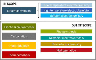 | ||
| Fig. 1 Overview of different approaches to convert CO2 into products. The category ‘Tandem electrochemistry’ refers to a combination of high- and low-temperature electroconversion of CO2 to products. | ||
We here examine six electroconversion routes that apply electricity as an energy carrier to directly convert CO2 into products by electrochemical means. Such an approach has several advantages in that it can: (1) accelerate the uptake of renewable electricity supply thanks to increased demand; (2) reduce the reliance of industry on fossil fuels by enhancing industrial electrification; (3) result in more efficient (ideally) single-step conversion processes that can lead to pure products and simplify purification steps.
In Chapter 2, we discuss the state-of-the-art in terms of the development stage and performance metrics of direct electrochemical CO2 conversion approaches. Several processes and products are thoroughly studied at the laboratory scale,10–16 but only a few are more advanced in their development stage. We have selected six routes, mainly based on the technology readiness level (TRL > 4: routes 1, 2, 4, and 5) and two potentially interesting approaches to produce ethylene (TRL 3–4: routes 3 and 6), for further techno-economic assessment (Table 1).
 ) indicate routes that are relatively advanced (TRL > 4) and are within the scope of this study. Beaker symbols (
 ) indicate processes that are currently at a relatively early development stage (TRL < 4) and are outside the scope of this study, except for two processes to produce C2H4. LT = low temperature; HT = high temperature; SOEC = solid oxide electrolysis cell; MCEC = molten carbonate electrolysis cell; FA = formic acid; MeOH = methanol; OxA = oxalic acid; EtOH = ethanol; PrOH = n-propanol
For these routes, we determine and discuss the current costs and apply learning curve analysis to project costs up to 2050 (Chapter 3). At that time, the technology needs to be competitive at an industrial scale in order to play a meaningful role in the energy transition. To contextualize the analysis of these CCU electrochemical conversion processes, the state-of-the-art of chlor-alkali production as an existing, industrial-scale electrochemical process has been evaluated as well. The chlor-alkali industry has demonstrated that it is feasible to build and operate industrial scale electrochemical installations. These installations will likely serve as a prime example for future electrochemical plants.
Next to costs, we also touch upon the associated CO2 emissions for each of the routes (Chapter 4). This greenhouse gas performance is important to understand the feasibility of the electrochemical routes in comparison to conventional fossil-based approaches. In Chapter 5, we provide an overview of knowledge gaps and research questions before presenting the conclusions in Chapter 6. We hope that the insight from our assessment helps people from universities, knowledge institutes, industry, and governments to steer developments in the right direction and to accelerate industrial transformation.
2 State-of-the-art
Electrochemistry may appear as an attractive approach to convert a stable molecule like CO2 into an array of carbon-based products, such as CO, FA, and C2H4. Here we investigate six routes to electrochemically convert CO2 to produce CO (2 routes), syngas (1 route), formic acid (1 route), and ethylene (2 routes). In these routes, two key technologies are applied, i.e. low temperature (LT) electrolysis and high temperature (HT) electrolysis. We first determine the technical status of the involved technology in terms of system size and configuration, energy and mass balances, current investment costs, technology readiness level (TRL) and existing projects. Electrochemical CO2 conversion processes are currently not industrially applied and we include the commercial chlor-alkali process as a reference and benchmark technology in our analysis. The methodology for our analysis has been described in more detail in the ESI.†2.1 Chlor-alkali process
The chlor-alkali electrolytic process is globally the main technology to produce chlorine and caustic soda. Three types of systems are widely applied: the mercury cell, diaphragm cell and membrane cell. The first two were commercialized in the late 19th century, while the membrane cell process was developed in the 1950s.17,18 Due to concerns around the use of mercury and asbestos in mercury and diaphragm cells respectively, the membrane cell process has become the dominant technology, possessing in the EU-27 a 60% share for chlorine production in 2012,19 and an 85% share in 2019.20 In all three processes, an electric potential is applied onto two electrodes to convert sodium chloride and water into sodium hydroxide, chlorine, and hydrogen (eqn (1)).| 2NaCl + 2H2O → 2NaOH + Cl2 + H2 | (1) |
Another novel approach has recently entered the market, the so-called oxygen-depolarised cathode (ODC) cell, which is an update of the membrane cell approach. Rather than co-producing H2, ODC cells consume O2 at the cathode (eqn (2)). This process benefits from a lower cell voltage (from around 3.0 V down to 2.0 V in the ODC) process and thereby reduces the total energy requirements by around 25% (per kg Cl2 produced).21 A schematic design and operation of an electrolysis cell is given in the ESI (Fig. S2†).
| 2NaCl + H2O + 1/2O2 → Cl2 + 2NaOH | (2) |
Globally, around 90 Mt Cl2 is annually produced next to around 100 Mt of caustic soda.22 To produce such an amount with an average stack electricity use of 2.4 MW h per ton of Cl2, a total worldwide installed electrolyser capacity of around 27 GW is required (at a 90% load factor). This capacity (mainly membrane technology) will likely increase to fulfil the chlorine demand of a growing chemical industry.20 Chlor-alkali electrolysis produces as a by-product around 2% of total global hydrogen.23 The equipment is supplied by several manufacturers around the world, such as Thyssenkrupp.24 These companies will likely also provide equipment for the water electrolyser industry and currently their combined annual equipment production capacity is roughly 2–3 GW per year in 2020.25–27 This capacity has substantially increased over the last years because many companies are preparing themselves for a rapidly increasing demand for electrolysers.
The mass and energy balances of the current membrane electrolysis chlor-alkali process are summarised in the diagram in Fig. 2.
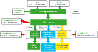 | ||
| Fig. 2 Overview of the chlor-alkali production process and the main material flows (reproduced from ref. 22). | ||
The complete chlor-alkali process starts from the NaCl salt and purified water. These two elements undergo a preparation process to produce the brine stream (concentrated aqueous salt solution) that will feed the electrolysis unit. The brine stream, along with the electricity input, yields the electrolysis process possible, producing a gaseous Cl2 stream (anode side), H2 (cathode side), and a concentrated aqueous caustic soda (NaOH) stream at the cathode. A post-treatment step for all three streams renders the final Cl2 product, a 50% NaOH (aq.) solution, and some H2 gas. A more detailed mass and energy balance is provided in the ESI (Table S2†).
The membrane electrolysis technology for the chlor-alkali process has undergone an optimisation process in terms of energy consumption, with new cell designs over the past 15 years. The new ODC design also represents a major improvement in the energy consumption for the chlor-alkali process (Fig. 3). The thermodynamic minimal energy requirements for both the H2 co-production system and the ODC design are indicated by the striped lines, showing the maximal optimisation potential of both technologies.
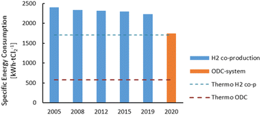 | ||
| Fig. 3 Evolution of the specific energy consumption for the production of Cl2 through the membrane electrolysis technology since 2005. H2 co-production is the conventional technology seen in Fig. 2 and the oxygen depolarised cathode (ODC) technology represents a novel design in which oxygen is used at the cathode. Plot constructed with data from ref. 14 and 17. | ||
2.2 Route 1: low-temperature CO2 electroconversion to carbon monoxide
The LT electrochemical reduction of CO2 into carbon monoxide (CO) consists of the electrolysis unit and a series of auxiliary units for the final production of a purified gaseous CO stream. A simplified process diagram is shown in Fig. 4. The overall reaction of the process is displayed in eqn (3). As is shown, CO2 is the only reactant in the process, yielding CO and O2.| CO2 → CO + 1/2O2 | (3) |
The current state of development for the LT CO2 conversion to CO technology is estimated to be at a TRL 5–6.28 In the Rheticus project, a joint venture between Siemens and Evonik, this process route is followed by a downstream unit that produces alcohols from the upstream electrochemical CO.29 The aim of this project is the construction and validation of a 25 kW electrolyser stack for the production of syngas (CO + H2), which will be fed to a bio-reactor for the fermentation into butanol and hexanol.
The technology involves the use of gas diffusion electrodes (GDEs) in a membrane electrode assembly (MEA) cell architecture, inspired by the PEM water electrolyser design.30 An anion exchange membrane (AEM) is used to allow ionic transport. A gaseous, humidified CO2 stream is fed at the back of the cathode GDE, producing CO and (undesired) H2 through the hydrogen evolution reaction. The cathode outlet stream contains CO2, H2O, CO and H2. A depiction of the MEA cell for LT CO2 to CO is shown in Fig. 5.
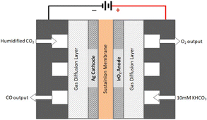 | ||
| Fig. 5 Schematics of a typical membrane electrode assembly (MEA) cell for CO2 electrolysis to CO (reproduced from Liu et al., 2018).34 | ||
The alkaline nature of the cathode acts as a trap for the fed CO2, converting it into carbonates. The negatively charged carbonates cross the AEM and end up in the anode compartment. There, given the acidic nature of the anode environment, carbonates are acidified and CO2 is released, along with O2, produced through water oxidation. A neutral anolyte can be used to supply water to the anode.
The CO2 utilisation degree (CO2UD) determines the extent to which CO2 is effectively converted to the product of interest. It is defined as the molar ratio of the CO2 converted to the product of interest and the total CO2 inlet to the cathode. The CO2UD can be calculated as the ratio of the faradaic efficiency (FE), defined as the efficiency with which electrons participate in a given electrochemical transformation, towards the product and the total CO2 consumed, as reported by Yang et al.31 In neutral or alkaline media, a theoretical maximum of CO2UD of 50% can be hypothesised for a 100% FE towards CO because of the concomitant formation of OH−. The latter reacts with CO2 to form HCO3− and CO32− ions.
 | (4) |
The gas outlet from the anode side will contain O2, CO2 and some H2O. Given the high O2 concentration in this stream, CO2 needs to be captured in an oxidation-resistant process, like a calcium caustic loop, used for direct air capture (DAC). Data were retrieved from Keith et al.32 for a caustic loop consisting of three steps: a pellet reactor, calciner, and slaker. We assume that the modelled loop for CO2 reclaiming uses electric energy as input for the HT steps and has as outputs a gas stream of CO2, which is recycled back to the cathode inlet of the LT electrolyser, and an O2 gas stream.
On the cathode outlet, a mixture of CO2 and CO (and traces of H2 and H2O) is sent to a pressure swing adsorption (PSA) unit for CO purification. The PSA unit delivers a commercial grade 98 vol% CO stream33 as the final output and a reject stream with CO2 and CO, which can be recycled to the electrolyser unit. In our calculations, the energy for this process is provided by electricity.
Typical process performance indicators for the LT electrolysis of CO2 to CO are reported in Table 2. At a cell voltage of around 3.0 V, the current density amounts to roughly 2000 A m−2, which is an order of magnitude lower than that observed for PEM water electrolysis. The CO2 utilisation degree depends on the FE and is close to its limit of 50% (see eqn (4)). We assume that the net carbon yield is 100%, which means that all CO2 ends up either in the product or else is recycled in the process. In reality, a fraction of the carbon is likely lost in the purge stream. The production of 1 kg of CO requires around 1.6 kg of CO2 and uses approximately 7.2 kW h of electricity. More detailed mass and energy balances of the process are shown in Table S3, while information concerning material use is provided in Table S10 (see the ESI).†
Expectations are that these performance parameters for LT CO2 electrolysis towards different products can be improved significantly. The development targets, in terms of current density, cell voltage, and power density for the current decade are described by Nørskov et al.28 and plotted in Fig. 6. The expected performance of LT CO2 electrolysis by 2030 will approach that of the current PEM water electrolysis technology in terms of current density and power density. The power density variable is the product of the cell voltage and the partial current density (FE times total current density) towards the product of interest and is a measure of the productivity of the cell in terms of delivered power per unit of electrode area.
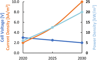 | ||
| Fig. 6 Roadmap for different process performance indicators for LT CO2 electrolysis for the current decade. Considered products are CO, FA, and C2H4. Reproduced from ref. 28. | ||
Our estimate of the investment costs for LT CO2 electrolysers is based on PEM water electrolysis, as the most comparable commercial technology available. The electrolysis unit investment costs are reported as a function of the total electrical installed capacity. The stack lifetime for the LT CO2 electrolysis stacks is taken from the PEM water electrolysis technology, given the lack of data on long-term testing of this process under industrially relevant conditions. An overview of long-term performance data for several electrolysis technologies is given by Küngas,30 reporting >4000 h of operation for an LT CO2 electrolysis unit for CO production. A summary of the different cost indicators is presented in Table 3. Given the different power densities for PEM water electrolysis and LT CO2 electrolysis, the reported values for investment costs for the PEM systems have been adapted to the performance indicators for LT CO2 electrolysis (see also ESI, eqn (5)).† The specific capital expenditure (CAPEX) for the LT CO2 electrolysis system amounts to 3200–7000€ per kW. The investment costs for the calcium caustic recovery loop for CO2 recovery from the anode side are based on a 235 M€ investment for a 123 tCO2 per h capture system.32 The PSA unit for CO purification costs around 1.7 M€ for 1000 Nm3 h−1.36,37 CAPEX for these two units is adapted to the size of our LT CO production plant using a scaling factor of 0.7.36 The total investment costs for the LT CO2 electrolysis to CO facility are calculated by applying an installation factor of 1.8 and adding 10% owner's costs over the installed costs and amount to 11![[thin space (1/6-em)]](https://www.rsc.org/images/entities/char_2009.gif) 700–19
700–19![[thin space (1/6-em)]](https://www.rsc.org/images/entities/char_2009.gif) 000€ per kW.
000€ per kW.
| Parameter | Unit | Value | Ref. |
|---|---|---|---|
| a Approximate uninstalled investment costs for a PEM electrolysis unit (stack and auxiliary equipment) for a 1 MW electrolysis unit in 2019. b The cost share of the different components reported by Böhm et al.39 refer to the first row of the table. c The ‘power density’ factor for PEM electrolysis is reported by Mayyas et al.40 for a PEM system with a performance of 17 kA m−2 at 1.7 V total cell voltage. | |||
| Total PEM electrolysis system (uninstalled costs)a | € per kW | 667–1450 | 38 |
| Stack cost shareb | — | 60% | 39 |
| Power electronics cost shareb | — | 15% | 39 |
| Gas conditioning cost shareb | — | 10% | 39 |
| Balance of plant cost shareb | — | 15% | 39 |
| Power density PEM electrolysisc | kW m−2 | 29 | 40 |
| Total LT CO2 electrolysis system (uninstalled costs) | € per kW | 3200–7000 | This study |
| Calcium caustic recovery loop unit | € per kW | 2100 | 32 |
| PSA CO/CO2 separation unit | € per kW | 540 | 36 and 37 |
| LT CO2 electrolysis plant to produce CO (total investment costs) | € per kW | 11![[thin space (1/6-em)]](https://www.rsc.org/images/entities/char_2009.gif) 700–19 700–19![[thin space (1/6-em)]](https://www.rsc.org/images/entities/char_2009.gif) 000 000 |
This study |
2.3 Route 2: low-temperature CO2 electroconversion to formic acid
The LT electrochemical reduction of CO2 into formic acid/formate consists of an electrolysis unit and a series of auxiliary units for the final production of a purified aqueous FA stream. A diagram of the complete process is shown in Fig. 7. The overall reaction process is displayed in eqn (5). The reactants CO2 and H2O are converted in the process into FA and O2.| CO2 + H2O → FA + 1/2O2 | (5) |
The current development stage for the LT CO2 conversion to FA is claimed to be at a TRL 3–5.41 The most important projects that aim to bring this process route to the next level are summarised in Table 4. The state-of-the-art for LT electrolysis of CO2 to FA involves the use of GDEs and a special electrochemical cell design with an acidic centre compartment for the direct production of FA and not the deprotonated formate (HCOO−). The production of HCOO− requires a costly downstream protonation step with, for instance, an electrodialysis process to generate FA, as reported by Ramdin et al.42
| Project | Framework | Involvement | Description |
|---|---|---|---|
| a OCEAN (2022).43 b e2C (2022).44 c Zhu (2019).45 | |||
| OCEANa | ASPIRE | AVANTIUM, ERIC, IIT, Gaskatel, Politecnico di Torino, RWE, Universiteit van Amsterdam | Achieve a TRL 6 development stage for the electrochemical conversion of CO2 to formate (250 g h−1 at 1500 A m−2) |
| e2Cb | Interreg 2-Seas | TNO, VITO, Universiteit Antwerp, Lille University, University of Sheffield, University of Exeter, TU Delft | Build a pilot demonstrator for the LT CO2 conversion to FA and validate the technology at TRL 6 |
| ECFORMc | — | DNV GL | Semi-pilot ECFORM demonstration reactor with a 600 cm2 surface area and a capacity of reducing approximately 1 kg CO2 per day and producing formic acid (85 wt%) |
An electrochemical cell design that is reported to directly produce a diluted (up to 10 wt%) FA aqueous stream is reported by Yang et al.47 The cell is a 3-compartment electrolyser, featuring a cathode GDE for the conversion of gaseous CO2 to HCOO− and an AEM directly attached to the cathode GDE that allows for the direct migration of HCOO− anions towards the centre compartment. In the middle compartment, acid cation exchange media are present to provide both electrical conductivity and protons to form FA from HCOO−. On the other side, an anode GDE compartment is fed with liquid water for O2 production. This GDE is directly attached to a CEM to allow for the transport of protons from the oxygen evolution reaction at the anode towards the centre compartment. The sketch of the said cell design is shown in Fig. 8.
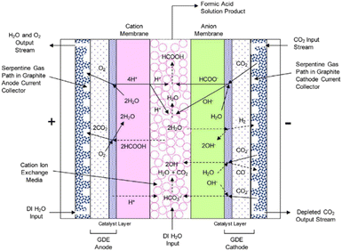 | ||
| Fig. 8 Schematic representation of the 3-compartment electrochemical cell for the direct production of FA through an LT CO2 electrolysis process, showing proposed electrochemical reactions and ion transport. Reproduced from Yang et al., 2017.46 | ||
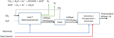
Analogously as for the LT CO2 to CO route, some CO2 will migrate from the gas compartment to the electrolyser in the form of (bi)carbonates. The CO2UD can also be assumed as half of the FE towards FA. The (bi)carbonate anions will cross towards the middle compartment, and, given the acidic nature of the latter (pH of ca. 1.0 for 10 wt% FA concentration),47 CO2 will be stripped out from this compartment, which can be easily separated from the aqueous FA stream with a flash unit, as seen in Fig. 7. Therefore, there is no need of adding a CO2 recovery loop for the anode outlet stream, as for the LT CO2 to CO route. The outlet FA stream from the flash unit is fed to a hybrid extraction–distillation process to achieve industrially relevant concentrations of FA > 85 wt% (aq.), as proposed by Ramdin et al.42 A simplified process flow diagram of this purification section is depicted in the ESI (Fig. S3†).
Our selected state-of-the-art process performance indicators for the LT electrolysis of CO2 to FA are reported in Table 5. The typical current density of 2000 A m−2 is in the same order of magnitude as for the CO process, but the required cell voltage of 3.75 V is slightly higher. The FE is slightly lower compared to that for CO production, because in the FA process also some H2 is formed. The CO2 utilisation degree is dependent on the FE towards FA, and consequently lower as for the CO case. The production of 1 kg of aq. 85 wt% FA solution requires around 0.81 kg of CO2 and uses approximately 6.0 kW h of electricity. More detailed mass and energy balances of the process and material use are shown in Tables S4 and S10,† respectively.
CAPEX for the electrolysis unit for the LT CO2 electrolysis to FA is determined analogously as for the LT CO2 to CO case (see Table 3), by using the power density of the FA production process. The specific CAPEX for the LT CO2 electrolysis system amounts to 2700–5700€ per kW (Table 6). The costs for the additional cation exchange membrane (107€ per kW) have been included.112 The costs of a downstream hybrid extraction and distillation train for formic acid purification have been described for a 1.0 tCO2 per h system and come to 7.9 M€.42 This system is scaled to the required size (scaling factor 0.7) and added to the total equipment costs. After correction for total project costs (installation factor 2.0), the total investment costs for the LT CO2 electrolysis to FA facility amount to 10![[thin space (1/6-em)]](https://www.rsc.org/images/entities/char_2009.gif) 700–16
700–16![[thin space (1/6-em)]](https://www.rsc.org/images/entities/char_2009.gif) 700€ per kW.
700€ per kW.
| Parameter | Unit | Value | Ref. |
|---|---|---|---|
| Total LT CO2 electrolysis system (uninstalled costs) | € per kW | 2700–5700 | This study |
| Hybrid extraction + distillation train | € per kW | 2700 | 42 |
| LT CO2 electrolysis plant to produce FA (total investment costs) | € perkW | 10![[thin space (1/6-em)]](https://www.rsc.org/images/entities/char_2009.gif) 700–16 700–16![[thin space (1/6-em)]](https://www.rsc.org/images/entities/char_2009.gif) 700 700 |
This study |
2.4 Route 3: low-temperature CO2 electroconversion to ethylene
The LT electrochemical reduction of CO2 into ethylene (C2H4) consists of an electrolysis unit, and a series of auxiliary units for the final production of a purified gaseous C2H4 stream. A diagram of the complete process is shown in Fig. 9. In the chemical reaction CO2 and H2O are converted into C2H4 and O2, as depicted in eqn (6).| 2CO2 + 2H2O → C2H4 + 3O2 | (6) |
LT CO2 conversion to C2H4 technology is being validated in the laboratory, which implies a TRL of 3–4.41 In two European projects this process route is further developed (Table 7). Currently, GDEs and a MEA-type of cell design are typically used, analogous to that for LT CO production (see Fig. 5). In the LT C2H4 case, a humidified CO2 gas stream is fed to the cathode GDE, which is separated with an AEM from the anode side. At the anode, an alkaline aqueous stream is fed to sustain the oxygen evolution reaction. The cathode outlet stream contains CO2, H2O, C2H4, other C-gaseous products, possible C-liquid products, and H2. A depiction of the MEA cell for LT CO2 to C2H4 is shown in Fig. 10.
| Project | Framework | Involvement | Description |
|---|---|---|---|
| a SELECT CO2 (2022).48 b Energiforskning (2022).49 | |||
| SELECT CO2a | EU Horizon 2020 | TU Berlin, EPFL, TU Delft, RINA, DTU, De Nora, Pretexo, University of Surrey, SLAC | Development of LT CO2 electrolysis technology to achieve TRL 4 for C2H4 production |
| Electrochemical CO2 reduction to ethylene for industrial applicationsb | Energi forskning | Siemens, DTU | Joint Siemens & DTU project for large-scale production of a generic electrode platform for electrochemical reduction of CO2 to ethylene |
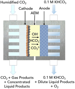 | ||
| Fig. 10 Schematic diagram of the MEA cell for the LT electrolysis of CO2 to C2H4. Reproduced from Gabardo et al. (2019).50 | ||
During the formation of a single molecule of C2H4, 12 electrons and 12 OH− molecules are produced. These hydroxides generate a highly alkaline environment at the cathode and act as a trap for the fed CO2, converting it into carbonates. As for the LT CO production case, these carbonates can migrate through the AEM towards the anode side. The CO2 lost to CO2 reacted ratio is even higher than for the LT CO scenario. Gabardo et al. reported a 4![[thin space (1/6-em)]](https://www.rsc.org/images/entities/char_2009.gif) :
:![[thin space (1/6-em)]](https://www.rsc.org/images/entities/char_2009.gif) 1 ratio for the CO2 lost to CO2 reacted (i.e., CO2UD = 20%).50 Sisler et al. report a more optimistic scenario of a 2
1 ratio for the CO2 lost to CO2 reacted (i.e., CO2UD = 20%).50 Sisler et al. report a more optimistic scenario of a 2![[thin space (1/6-em)]](https://www.rsc.org/images/entities/char_2009.gif) :
:![[thin space (1/6-em)]](https://www.rsc.org/images/entities/char_2009.gif) 1 ratio (CO2UD = 33%).51 Due to the CO2 crossover from the cathode to the anode, the gas outlet from the anode side contains O2, CO2 and some H2O. A calcium caustic recovery loop for CO2 reclaiming is considered, as it was done for the LT CO case. The recovered CO2 from this loop will be fed back to the cathode inlet of the LT electrolyser. On the cathode outlet, a mixture of CO2, C2H4, and traces of H2 and H2O is sent to a PSA unit for C2H4 purification. The final outputs from this PSA unit will be a commercial grade 99.9 wt% C2H4 stream,52 and a reject stream with CO2 and C2H4. A simplified process diagram of the complete LT C2H4 production process is shown in Fig. 11.
1 ratio (CO2UD = 33%).51 Due to the CO2 crossover from the cathode to the anode, the gas outlet from the anode side contains O2, CO2 and some H2O. A calcium caustic recovery loop for CO2 reclaiming is considered, as it was done for the LT CO case. The recovered CO2 from this loop will be fed back to the cathode inlet of the LT electrolyser. On the cathode outlet, a mixture of CO2, C2H4, and traces of H2 and H2O is sent to a PSA unit for C2H4 purification. The final outputs from this PSA unit will be a commercial grade 99.9 wt% C2H4 stream,52 and a reject stream with CO2 and C2H4. A simplified process diagram of the complete LT C2H4 production process is shown in Fig. 11.
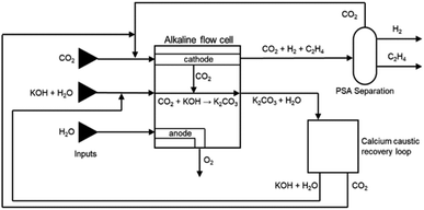 | ||
| Fig. 11 Process flow diagram for CO2 reduction towards ethylene in an alkaline flow cell. Reproduced from Sisler et al. (2021).51 | ||
Current state-of-the-art process performance indicators for the LT electrolysis of CO2 to C2H4 are reported in Table 8. The current density of 1200 A m−2 is slightly lower in comparison to the processes to produce CO and FA. The cell voltage of 3.7 V is similar to that of electrochemical FA production. The co-production of hydrogen and other carbon-based compounds lowers the FE towards the desired product, C2H4. Also, the carbon yield is below 100% because some side-products are formed, such as CO and ethanol. The production of 1 kg of C2H4 consumes approximately 4.7 kg of CO2 and 80 kW h of electricity. The overall C2H4 yield could potentially be enhanced by feeding the electrochemical cell with a CO2–CO mixture, as there is no site competition between both reactants on the reactive catalyst surface. Therefore, C2H4 could be produced electrochemically from an impure CO2 stream containing CO, which is quite common at an industrial scale for CO2 feeds.53 The complete mass and energy balances for the LT electrolysis of CO2 to C2H4 process are shown in Table S5 and information on the use of materials is provided in Table S10 (see the ESI).†
| Parameter | Unit | Value | Ref. |
|---|---|---|---|
| a The carbon yield to product is calculated as the ratio between the FE towards C2H4, and the FE towards all carbon-products (Cprod, incl. C2H4). | |||
| Current density | A m−2 | 1200 | 54 |
| Cell voltage | V | 3.70 | 53 |
| Faradaic efficiency | — | 64% (C2H4) | 53 |
| 74% (all Cprod) | |||
| CO2 utilisation degree | molC2H4/molCO2 in | 20% | 53 |
| Carbon yielda | molC2H4/molCO2 reduced | 86% | Calculated |
| Power density | kW m−2 | 4.4 | Calculated |
| Stack lifetime | h | 40![[thin space (1/6-em)]](https://www.rsc.org/images/entities/char_2009.gif) 000 000 |
35 |
The estimation of the investment costs for the electrolysis unit for the LT CO2 electrolysis to ethylene is done analogously to the previous routes (see Tables 3 and 6). The PSA unit is based on data from the LT CO2 to CO case (Table 3) and adapted to the present route. Total specific investment costs for the plant amount to 10![[thin space (1/6-em)]](https://www.rsc.org/images/entities/char_2009.gif) 300–20
300–20![[thin space (1/6-em)]](https://www.rsc.org/images/entities/char_2009.gif) 400€ per kW (Table 9).
400€ per kW (Table 9).
| Parameter | Unit | Value | Ref. |
|---|---|---|---|
| Total LT CO2 electrolysis system (uninstalled costs) | € per kW | 4400–9600 | This study |
| Calcium caustic recovery loop unit | € per kW | 580 | 32 |
| PSA CO/CO2 separation unit | € per kW | 200 | 36 and 37 |
| LT CO2 electrolysis plant to produce C2H4 (total investment costs) | € per kW | 10![[thin space (1/6-em)]](https://www.rsc.org/images/entities/char_2009.gif) 300–20 300–20![[thin space (1/6-em)]](https://www.rsc.org/images/entities/char_2009.gif) 400 400 |
This study |
2.5 Route 4: high-temperature solid oxide CO2 electroconversion to carbon monoxide
High-temperature (HT) electrolysis in a solid oxide electrolyser (SOE) is the only CO2 electrolysis technology that is approaching commercialization (TRL 8).30 The technology is based on solid oxide cell (SOC) technology presented in Fig. 12, composed of ceramic-based components (cathode and anode electrodes and electrolyte) able to produce CO via the electrolysis of CO2 at elevated temperatures (600–800 °C). According to the SOC principle, CO2 is fed to the cathode side of the cell via gas channels, which helps to distribute the gas across the cell. In the porous cathode (fuel electrode) CO2 is reduced to CO. The electrons for the reaction are provided by an external power supply. The oxide ions (O2−) formed in the reaction are incorporated into the electrolyte and traverse through the electrode into the anode, where the ions are oxidized into molecular oxygen.30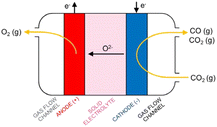 | ||
| Fig. 12 Principle of CO production in a solid oxide cell (Küngas, 2020).30 | ||
The SOE concept for CO production has been exclusively developed on the system scale by the technology supplier Topsøe.30 Topsøe technology is based on electrode-supported SOC technology (Fig. 13, top left), operating at a temperature of 700 °C, thanks to the thin Yttria-stabilized zirconia (YSZ) electrolyte design allowing the conduction of O2− ions at this temperature with a low internal resistance, a Ni-YSZ fuel electrode cermet (cathode) able to convert CO2 into CO and a perovskite-based anode La0.6Sr0.4Co0.2Fe0.8O3- (Ce0.9Gd0.1)O1.95 (LSCF-CGO) able to reconvert O2− ions into O2 (see also Table S10†). All layers constitute the core of the single repeating SOC units assembled in a stack design (Fig. 13) with the addition of metallic-based bipolar separators and end plates enabling gas and current transfer through the cell and stack and sealing components next to each bipolar separator plate to prevent gas-crossing between the anode and cathode sides.
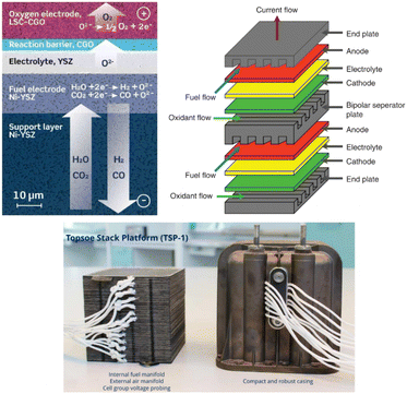 | ||
| Fig. 13 Top left: electrode supported solid oxide cell design (reproduced from Hauch et al., 2020),55 top right: scheme of two single repeating SOC units design in a SOE stack (reproduced from Singhal, 2014),56 bottom left: Topsøe stack design developed for CO production (reproduced from Küngas et al., 2019).58 | ||
Topsøe developed this stack technology for direct implementation on the system level for CO production at an industrial site, in a stand-alone unit connected with power, CO2, and product gas, as shown in Fig. 14. It can produce on-demand capacities ranging from 1 to 250 kg h−1 of CO.
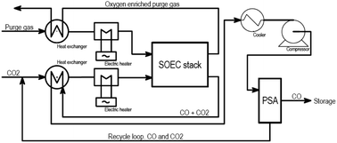 | ||
| Fig. 14 Block flow diagram for Topsøe's eCOS unit for the SOE CO2 to CO process (Duhn, 2017).57 | ||
Single-pass conversion of CO2 to CO depends on the operating temperature of the SOE stack (Duhn, 2017).56 The limitation for high single-pass conversion of CO2 is due to carbon formation by the Boudouard reaction and resulting degradation of the cell. For the base case, a single-pass CO2 conversion of 50% is assumed and the overall conversion is assumed to be 100%. Hence, on a system level, 1 mole of CO2 will produce 1 mole of CO. The electric power consumption for the stack varies between 2.6 and 2.8 kW h kg−1 of CO and depends on the operating voltage.58 Total system energy consumption depends on the level of heat integration and single-pass CO2 conversion. The total energy consumption for the system will be between 4.7 and 6.3 kW h per kg CO produced. Based on stoichiometry, for 1 mole of CO produced, 0.5 mole of oxygen will be produced. The oxygen has to be diluted in the process with sweep air due to safety issues in the stack. In the PSA unit, there will be a trade-off between yield and purity of CO.59 We assume a commercial grade CO product purity of around 98 vol%, analogously to the LT CO production process.33 Current process performance parameters for CO production are shown in Table 10. The current density of 7500 A m−2 is almost four times higher in comparison to the LT process (Table 3), while the cell voltage remains at around 1.4 V. This results in a power density of 11 kW m−2 for the HT process. The stack lifetime is estimated to be around 8000 hours.57 The overall mass and energy balance for the CO2-SOE production system is shown in Table S6.†
The total uninstalled CAPEX for the system is calculated based on the steam electrolysis data taken from Hydrogen Europe targets. Here, the system capacity is assumed to be 1 MWe. The split of CAPEX was assumed to be 30% for the cell stack, 30% for the power electronics, 6% for the gas conditioning, and 34% for the balance of plant.39 CAPEX for CO2 electrolysis is scaled based on the ratio of power density (kW m−2) for steam and CO2 electrolysis. Further, CO2 electrolysis will require an additional PSA separation unit compared to steam electrolysis. CAPEX of 600€ per kW for the PSA unit has been calculated by taking the total flow rate of CO2 and CO entering the PSA unit as basis.37 The total investment costs of CO2-SOE systems for CO production amount to 4200–6600€ per kW. A summary of the different cost indicators is presented in Table 11.
| Parameter | Unit | Value | Ref. |
|---|---|---|---|
| a Approximate uninstalled investment costs for a SOE unit (stack and auxiliary equipment) for a 1 MW electrolysis unit in 2020. b The cost share of the different components reported by Böhm et al.39 refer to the first row of the table. c The ‘power density’ factor for SO electrolysis is reported by Foit et al.59 for a SOE system with a performance of 7.5 kA m−2 at 1.5 V total cell voltage. | |||
| Total SOE system (uninstalled costs)a | € per kW | 520–2130 | 61 |
| Stack cost shareb | — | 30% | 39 |
| Power electronics cost shareb | — | 30% | 39 |
| Gas conditioning cost shareb | — | 6% | 39 |
| Balance of plant cost shareb | — | 34% | 39 |
| Power density SOEc | kW m−2 | 11 | 59 |
| Total HT CO2-SOE system (uninstalled costs) | € per kW | 1500–2700 | This study |
| PSA CO/CO2 separation unit | € per kW | 600 | 36 and 37 |
| HT CO2-SOE plant to produce CO (total investment costs) | € per kW | 4200–6600 | This study |
Despite achieving high TRL completion (TRL8) for CO production, SOE technology shows constant development at the cell, stack and system levels to reduce system costs for viable commercial implementation in the industrial sector (TRL9). CAPEX cost reduction can be achieved through the reduction of critical raw material (CRM) content (e.g. Co, Sr, Y…) in the SOE cell manufacturing,62,63 reduction of stack (<150k€ per kW) and system (<500k€ per kW) costs64 and improvement of the yield of production for mass integration in the industry,65 while improving efficiency of the SOE cell (high current density operations), stack (high fuel utilization) and system (heat & gas recycling) components.
OPEX reduction is aimed at by increasing the SOE cells and stack lifetime (≫ 8000 h) with the prevention of the coking process (Boudouard reaction) and sulphur poisoning at the fuel electrode (cathode) side. This can be realized through optimization of the robustness of the cell and stack components & design, with the development of alternative materials compared to the highly reactive state-of-the-art Ni-YSZ cermet fuel electrode.66 Tuning of the operating conditions of the SOE stack (temperature, pressure, current density) and integration of purification systems (desulfurization) in the BoP of the SOE system are also under development to prevent poisoning issues at the fuel side of the stack.67
2.6 Route 5: high-temperature solid oxide CO2 electroconversion to syngas
Syngas (H2/CO) of tuneable ratios can be produced in one single electroconversion process step at HT with a similar operating principle in solid oxide cells to that used for CO production (as shown in Fig. 15). The operating concept of the SOE for syngas production consists of a co-electrolysis (co-SOE) of water and CO2, able to produce variable H2 and CO compositions, for further process applications, as for instance, production of green fuels and chemicals such as methane and methanol. Steam and CO2 are reduced in the SOEC according to eqn (7), with the H2/CO ratio in the syngas modified by variations of the steam and CO2 flows.| CO2 + H2O → CO + H2 + O2 | (7) |
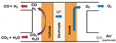 | ||
| Fig. 15 Schematical concept of a SOE cell for HT co-electrolysis of steam and CO2 to produce syngas. | ||
The production of syngas (H2/CO) using co-SOE is in the development phase with an achieved TRL of 5 to 6. The German system supplier Sunfire is the world leader and is known as the only system supplier for co-SOE systems (Fig. 16).68 The Sunfire system is based on a high-temperature operation (850 °C), with electrolyte-supported cells and stack technology (Fig. 17). The actual system is developed on a 150 kW scale, with the so-called name Syn-link (Fig. 17).
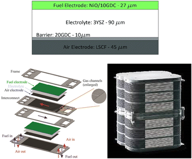 | ||
| Fig. 16 Sunfire solid oxide cell and stack technology for co-SOE electrolysers (Masini et al., 2019; Sunfire, 2022).69,70 | ||
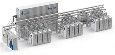 | ||
| Fig. 17 150 kW co-SOE Syn-link system developed at Sunfire (Sunfire, 2022).71 | ||
The co-SOE technology has been developed within multiple European research projects. To the best of our knowledge, the past and on-going projects for the development of co-SOE systems from kW to MW scale are summarized in Table 12.
| Project | Period | Involvement | Description |
|---|---|---|---|
| a Eco (2019).72 b Kopernikus (2019).73 c Norsk e-fuel (2022).74 d MegaSyn (2022).75 | |||
| Eco projecta | 2016–2019 | co-SOE concept for methane production | |
| Kopernikusb | 2016–2019 | Sunfire | Development of a 10 kW co-SOE system by Sunfire |
| Norsk e-fuelc | 2019–2025 | Development of the co-SOE technology for production of green-fuel for aviation & maritime transport, from CO2 captured from the air and renewable energy sources | |
| MegaSynd | 2021–2025 | FCHJU project | Demonstration of large-scale co-electrolysis for the industrial power-to-X market: first demonstration of syngas production by co-electrolysis on the mega-watt scale in an industrial environment at the Schwechat Refinery in Austria, with Sunfire technology |
For the calculations in this study, a syngas composition of H2![[thin space (1/6-em)]](https://www.rsc.org/images/entities/char_2009.gif) :
:![[thin space (1/6-em)]](https://www.rsc.org/images/entities/char_2009.gif) CO = 2
CO = 2![[thin space (1/6-em)]](https://www.rsc.org/images/entities/char_2009.gif) :
:![[thin space (1/6-em)]](https://www.rsc.org/images/entities/char_2009.gif) 1 is assumed. This syngas ratio corresponds approximately to the ratio required for fuel production through the Fischer–Tropsch process and methanol synthesis. The mass balance for the base case is based on stoichiometry calculations. The operating conditions are similar to those of HT CO production, although the cell voltage is slightly lower, i.e. 1.3 V (Table 13). The single-pass conversion of CO2 and H2O for the base case is assumed to be 80%.76Fig. 18 shows the conceptual block flow diagram for syngas production using an HT SOE system.
1 is assumed. This syngas ratio corresponds approximately to the ratio required for fuel production through the Fischer–Tropsch process and methanol synthesis. The mass balance for the base case is based on stoichiometry calculations. The operating conditions are similar to those of HT CO production, although the cell voltage is slightly lower, i.e. 1.3 V (Table 13). The single-pass conversion of CO2 and H2O for the base case is assumed to be 80%.76Fig. 18 shows the conceptual block flow diagram for syngas production using an HT SOE system.
The outlet gas mixture produced from SOE systems (H2![[thin space (1/6-em)]](https://www.rsc.org/images/entities/char_2009.gif) :
:![[thin space (1/6-em)]](https://www.rsc.org/images/entities/char_2009.gif) CO
CO![[thin space (1/6-em)]](https://www.rsc.org/images/entities/char_2009.gif) :
:![[thin space (1/6-em)]](https://www.rsc.org/images/entities/char_2009.gif) CO2
CO2![[thin space (1/6-em)]](https://www.rsc.org/images/entities/char_2009.gif) :
:![[thin space (1/6-em)]](https://www.rsc.org/images/entities/char_2009.gif) steam) requires additional separation processes to feed clean syngas (H2/CO) for the sub-mentioned fuels and chemical production processes (depending on the end-use of syngas). Steam is commonly removed by a condensation process and recycled into the steam system. CO2 can be separated from the (H2
steam) requires additional separation processes to feed clean syngas (H2/CO) for the sub-mentioned fuels and chemical production processes (depending on the end-use of syngas). Steam is commonly removed by a condensation process and recycled into the steam system. CO2 can be separated from the (H2![[thin space (1/6-em)]](https://www.rsc.org/images/entities/char_2009.gif) :
:![[thin space (1/6-em)]](https://www.rsc.org/images/entities/char_2009.gif) CO
CO![[thin space (1/6-em)]](https://www.rsc.org/images/entities/char_2009.gif) :
:![[thin space (1/6-em)]](https://www.rsc.org/images/entities/char_2009.gif) CO2) gas stream by absorption, adsorption, or membrane-based separation methods. Moreover, absorption-based separation with amine solutions is commercially available. Separated CO2 is recycled to the inlet of the SOE system. However, the separation of CO2 from syngas depends on the end-use of the produced syngas (for instance, for methanol production, the syngas inlet feedstock can contain CO2). The heat from SOE outlet gases is recovered using heat exchangers to increase the overall system energy efficiency. The stack lifetime equals around 40
CO2) gas stream by absorption, adsorption, or membrane-based separation methods. Moreover, absorption-based separation with amine solutions is commercially available. Separated CO2 is recycled to the inlet of the SOE system. However, the separation of CO2 from syngas depends on the end-use of the produced syngas (for instance, for methanol production, the syngas inlet feedstock can contain CO2). The heat from SOE outlet gases is recovered using heat exchangers to increase the overall system energy efficiency. The stack lifetime equals around 40![[thin space (1/6-em)]](https://www.rsc.org/images/entities/char_2009.gif) 000 hours based on Posdziech,77 which is substantially higher compared to the 8000 h reported by Topsøe for CO production.57 This difference is explained by the degradation of the stack due to carbon formation in the latter process. The total electricity input for the plant to produce a kg of syngas is 8.1 kW h of which nearly 90% is consumed by the stack. The overall mass balance for syngas production is given in Table S7 and information about the materials used can be found in Table S10 (ESI).†
000 hours based on Posdziech,77 which is substantially higher compared to the 8000 h reported by Topsøe for CO production.57 This difference is explained by the degradation of the stack due to carbon formation in the latter process. The total electricity input for the plant to produce a kg of syngas is 8.1 kW h of which nearly 90% is consumed by the stack. The overall mass balance for syngas production is given in Table S7 and information about the materials used can be found in Table S10 (ESI).†
The total uninstalled CAPEX for the system is calculated based on steam electrolysis data taken from Hydrogen Europe60 targets in a similar fashion to that for CO production (see Table 11). Syngas electrolysis will likely require additional separation compared to steam electrolysis. CAPEX for the separation unit has not been included and, if deemed necessary, may increase the overall investment and production costs of this route. The total investment costs for a HT electrochemical syngas production plant range between 3000 and 5400€ per kW (Table 14).
| Parameter | Unit | Value | Ref. |
|---|---|---|---|
| Total HT CO2-SOE system (uninstalled costs) | € per kW | 1500–2700 | This study |
| HT CO2-SOE plant to produce syngas (total investment costs) | € per kW | 3000–5400 | This study |
Besides SOECs, molten carbonate electrolysis cells (MCECs) can also be applied to electrochemically produce CO or syngas at high temperatures (600–900 °C).78 Although MCEC system development has only reached a TRL of 4, the use of this technology for syngas and CO production has a promising perspective for industrial implementation. This is because MCFC technology, the reversible MCEC concept, is already commercialized on an industrial scale (TRL 9) for power and heat generation with units of up to 3.7 MW sold by Fuel Cell Energy79 and POSCO80 and several power plants of 10–60 MW are already installed worldwide.81 In our analysis, the MCEC concept is nevertheless not included as a separate route because, due to the development at low TRL, information on the system development (stack cost and effective operation) is lacking. More details on the process and state-of-the-art can be found in the (ESI, Section 2.7).†
2.7 Route 6: tandem electroconversion approach to produce ethylene
The tandem process for the production of C2H4 consists of the combination of a HT electrolysis unit for CO2 electrolysis towards CO (and the subsequent downstream processes for CO purification), followed by a LT electrolysis step for the conversion of the intermediate CO into C2H4, including auxiliary units for the purification and separation of C2H4. A diagram of the complete process is shown in Fig. 19. The individual reactions of the HT step and the LT step are displayed in eqn (8) and (9) below.| Step 1: HT CO2 electrolysis: 2CO2 → 2CO + O2 | (8) |
| Step 2: LT CO electrolysis: 2CO + 2H2O → C2H4 + 2O2 | (9) |
 | ||
| Fig. 19 Process diagram of the tandem HT CO2 electrolysis to CO and LT CO electrolysis towards C2H4, the so-called tandem process. Adapted from Sisler et al., 2021.51 | ||
The overall reaction of the tandem process, which is as expected equivalent to that of the LT CO2 conversion route towards C2H4, is displayed in eqn (10).
| 2CO2 + 2H2O → C2H4 + 3O2 | (10) |
The current development stage of the tandem route for C2H4 synthesis is limited by the LT conversion step, given that the HT step has already achieved a TRL 8–9 (see route 4). The LT CO electrolysis to products (C2+, specifically C2H4) has been explored experimentally, and can be considered to be at a TRL 3.82,83 The HT step for CO2 electrolysis towards CO has already been discussed in route 4. LT electrolysis of CO to C2H4 comprises the use of a MEA cell design, in which a gaseous CO stream is fed to the electrolyser, to the gas side of the cathode GDE. The cathode is separated from the anode with an ion exchange membrane (either CEM or AEM). In the anode compartment, an alkaline anolyte is fed as a reactant for the OER. The cathode outlet stream contains CO, H2O, C2H4, other C-gaseous products, possible C-liquid products, and H2. A depiction of the MEA cell for LT CO to C2H4 is shown in Fig. 20.
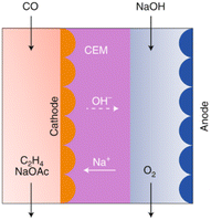 | ||
| Fig. 20 CO electrolyser design for the production of C2H4, with a CEM and an alkaline anolyte for the OER. Reproduced from Jouny et al., 2019.82 | ||
In the HT step for CO2 electrolysis towards CO, a PSA unit is included in the process diagram to allow for CO purification (see route 4). Also in the LT step for CO electrolysis, a PSA unit is included to ensure the required purity for the C2H4 gas stream (99.9 wt%, according to the NIH, 2022).52
Contrary to the LT CO2 electrolysis routes, the nature of the LT CO electrolysis process does not allow for the formation of bicarbonates or any crossover of the cathodic reactant towards the anode, as stated by Sisler et al.51 The fed CO in the second step of LT CO electrolysis will react electrochemically to form different CO reduction products, or it will leave the electrolyser unreacted, but it will not end up in the anode side. Therefore, there will be no need to implement a (CO) recovery loop in contrast to the CO2 recovery step that is required for the LT CO2 electrolysis towards C2H4 (see route 3). The process performance for the first electrolysis step is described in route 4. The second step, the LT electrolysis of CO to C2H4, is reported in Table 15. The total process to produce 1 kg of ethylene consumes 60–66 kW h of electricity of which approximately 85% is used by the LT conversion step. In the HT step, 5.0–5.5 kg of CO2 is converted into 3.2–3.3 kg CO, the latter is used in the LT step to produce 1 kg of C2H4 and some H2 and ethanol as side-products. These steps together generate as a by-product 8.4–8.5 kg of O2. The complete mass and energy balance for the tandem CO2 to C2H4 process is shown in Table S9.†
| Parameter | Unit | Value | Ref. |
|---|---|---|---|
| a The carbon yield to product is calculated as the ratio between the FE towards C2H4, and the FE towards all carbon-products (Cprod, incl. C2H4). | |||
| Current density | A m−2 | 1440 | 84 |
| Cell voltage | V | 2.3 | 83 |
| Faradaic efficiency | — | 35% (C2H4) | 83 |
| 56% (all Cprod) | |||
| CO2 utilisation degree | molC2H4/molCO in | 100% | 51 |
| Carbon yielda | molC2H4/molCO reduced | 63% | Calculated |
| Power density | kW m−2 | 3.34 | Calculated |
| Stack lifetime | h | 40![[thin space (1/6-em)]](https://www.rsc.org/images/entities/char_2009.gif) 000 000 |
35 |
For the tandem route, there will be two major components for the investment costs: the HT CO2 to CO electrolyser (incl. the PSA unit), and the LT CO electrolyser to produce C2H4, with the downstream PSA unit. The method for estimating the investment costs is analogous to that for the rest of the routes, i.e. the HT step is based on data for HT solid oxide steam electrolysis and the LT step on PEM water electrolysis and both are corrected for the power density factors. The capacity of the HT electrolyser is adjusted to the required CO demand for the LT CO electrolyser. The total specific CAPEX for the two-step process is slightly higher in comparison to route 3, the single-step LT route to produce ethylene, and amounts to 12![[thin space (1/6-em)]](https://www.rsc.org/images/entities/char_2009.gif) 300–25
300–25![[thin space (1/6-em)]](https://www.rsc.org/images/entities/char_2009.gif) 700€ per kW (Table 16).
700€ per kW (Table 16).
| Parameter | Unit | Value | Ref. |
|---|---|---|---|
| a The capacity of the HT system is adjusted to the capacity (in kW) of the LT system. | |||
| Total HT CO2 electrolysis and purification system (uninstalled costs) | € per kWa | 260 | This study |
| Total LT CO electrolysis and purification system (uninstalled costs) | € per kW | 6000–12![[thin space (1/6-em)]](https://www.rsc.org/images/entities/char_2009.gif) 700 700 |
This study |
| Tandem HT-LT CO2 electrolysis plant to produce C2H4.(total investment costs) | € per kW | 12![[thin space (1/6-em)]](https://www.rsc.org/images/entities/char_2009.gif) 300–25 300–25![[thin space (1/6-em)]](https://www.rsc.org/images/entities/char_2009.gif) 700 700 |
This study |
A summary of the design and material usage for each of the technologies used in the different routes is provided in Table S10 (see the ESI).†
3 Techno-economic analysis
Here, we report the results of our production cost assessment of the six routes. The routes consist of three LT electrochemical conversion routes that either produce CO, formic acid, or ethylene, two HT routes to produce CO or syngas, and one tandem approach (combination of HT and LT technology) to produce ethylene. The sensitivity analysis and cost projections up to 2050 are presented and discussed.3.1 Investment costs
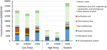
A more detailed description of the investment costs for the different routes is provided in the state-of-the-art sections (see above). In Fig. 21, we compare the cost breakdown of the base case total investment costs (CAPEX) for each of the routes for 1 MW scale plants. The LT conversion technology is currently significantly more expensive per kW of electricity input compared to the HT routes (4 and 5). This is also observed for the tandem process (route 6) in which the contribution of the first HT step (HT CO production system, dark green area) is barely noticeable (ca. 1% of the total CAPEX). The stack costs for LT systems are based on PEM technology for hydrogen production (see Table 3). For CO2 reduction, the stack is operated at a lower power density, which results in significantly higher costs per kW electricity input. Next to relatively high specific stack costs, the presence of the CO2 recovery loop, along with the purification unit for the end-product (PSA for gaseous products, and distillation for formic acid), represent a large contribution to the high total investment costs.The system and operating power density for our HT CO2 reduction routes are fairly similar to those of HT steam electrolysis for hydrogen production. This allows us to base our cost calculations on steam electrolysis data, which is reported in more detail. For route 4, we add the costs of a PSA unit to separate CO from CO2 of which the latter is recycled to the stack. For syngas production (route 5), we assume the synthesis gas that is produced is ready for use in, for instance, a methanol synthesis reactor, and does not require any further purification step. Such a step might appear necessary if the product gas is not directly suitable for follow-up chemical processes.
Our total investment costs cover nearly all project costs to build a CO2 electrochemical conversion plant. Next to direct equipment costs, the installation and owner's costs are also included and represent roughly half of the total plant costs. In the refining and petrochemical industries, typically an installation factor of around 3–5 is used to acquire a rough estimate of the total project costs based on the costs for the main equipment.85,86 If we only consider the electrolyser stack and power electronics as main equipment, our estimates correspond reasonably well with this factor. If other balance of plant costs, gas conditioning, and purification units (e.g., PSA/CO2 recovery loop) are included in the main equipment costs, our applied installation factor (∼2) seems relatively low for a chemical process plant. We justify our choice by using a similar installation factor as applied for capital cost calculations for large electrolytic hydrogen production plants.87
In comparison to specific investment costs of other chemical processes, such as water electrolysis38,86,88,89 or methanol synthesis,90,91 the costs corresponding to electrochemical CO2 conversion processes are relatively high, especially the LT routes. This can be expected of technologies at a low TRL because these do find themselves still at the start of their learning curve and significant cost reductions can be expected as soon as these technologies are further developed and scaled up. The effect of the investment costs on the levelized production costs is explained in the next section.
3.2 Levelized production costs
Current market prices of the products can provide a reasonable indication of the possible competitiveness of our routes. For bulk syngas and CO, it is difficult to estimate such a price because the market is non-existing. These gases are highly toxic and generally produced and directly converted into other products on site. To approximate a fossil-based reference price, a figure between the price of natural gas and methanol is chosen, ranging in 2019 between 7 and 12€ per GJ.92 To accommodate for recent volatility in natural gas and methanol prices,93 we increased our high estimates by approximately 50%. Our reference price is, thus, fixed at 7–18€ per GJ or 0.07–0.18€ per kg CO or 0.17–0.43€ per kg syngas. As a specialty chemical in gas cylinders, CO sells at a price that is an order of magnitude higher. Formic acid is mainly produced through the reaction of methanol with CO to form methyl formate, which is subsequently hydrolysed. Market prices varied approximately from 130 to 150€ per GJ or 0.70–0.80€ per kg FA in early 2022.94 Ethylene is typically produced via steam cracking of naphtha or natural gas liquids. The market price in the first quarter of 2022 varied between around 16 to 27€ per GJ or 0.70–1.30€ per kg C2H4.95As described in the Methodology section (see the ESI†), our levelized production cost calculations rely on investment costs, operating and maintenance (O&M) costs (of which we separately specify the stack replacement costs), and feedstock costs (incl. electricity, CO2, and H2O). The total investments for each of the routes, as presented in the previous section, are annualized by multiplying with the capital recovery factor using a discount rate of 10% and a plant lifetime of 20 years. The annual O&M costs are a fixed percentage of the initial total investment costs. We average out the replacement costs for the stack as a separate annual O&M cost component. For the base case, costs for electricity are 40€ per MW h, for CO2 50€ per tCO2, and for H2O 1€ per tH2O. More information can be found in the ESI (e.g., Table S1).†
Fig. 22 shows the results of the levelized cost calculations for our base case. From the figure, it is clear that the stack replacement, O&M and investment costs are driving the levelized costs of all products and routes.
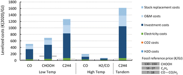 | ||
| Fig. 22 Base case levelized production costs of different CO2 electrochemical conversion routes. A breakdown of the costs is indicated by the coloured areas for each of the key cost components. Note the strong uncertainty related to CAPEX assessment of early stage technologies which have never been built and operated in a commercial environment. More details can be found in the enlarged diagrams in Fig. 25–30. | ||
For LT electrochemical CO2 conversion, the levelized costs to produce CO amount to approximately 500€ per GJ or 5.1€ per kg (Fig. 22). Investment costs contribute more than 60%, O&M costs (incl. stack replacements) cover just above 30%, and the feedstocks, electricity and CO2, together less than 10%. The investment costs dominate the LT CO production costs. This effect is typically exaggerated for low TRL technologies because several parameters (indirect investment costs and O&M cost components) are related to the main equipment costs.
Formic acid can be produced for almost 700€ per GJ or 3.7€ per kg (Fig. 22). The distribution of the costs over the different components is nearly identical to that of the LT CO production route. The costs per GJ of FA are slightly higher compared to those of CO. This can be explained by the lower energy efficiency of the formic acid production process with respect to CO production (resp. 26% vs. 40%). This difference in cost per GJ product becomes more apparent for C2H4 production for which the energy efficiency is only 16%. The lower the efficiency, the more capacity in kW is required to produce a GJ of product, next to additional expenses for electricity. Together this results for the direct process (route 3) in levelized costs of nearly 1270€ per GJ or 60€ per kg ethylene of which the feedstock costs (electricity, CO2, and H2O) only represent 6% in total, while the rest is for CAPEX (60%), O&M (20%), and stack replacement costs (14%). The tandem process (route 6), which is slightly less efficient and has higher CAPEX, is even more expensive than route 3 and costs amount to more than 1600€ per GJ or 76€ per kg ethylene. The ethylene production costs are approximately two orders of magnitude higher than our fossil reference price.
The HT processes benefit from relatively lower investment costs and higher energy efficiency. The levelized costs to produce CO are slightly below 200€ per GJ or 1.9€ per kg for route 4 (Fig. 22). Nearly a quarter of these costs come from the stack replacement costs, which are relatively high due to the low stack lifetime of only 8000 hours. Despite having an advantage in costs over the LT route (route 1), our fossil reference price is still at least ten times lower. Syngas production via HT route 5 results in levelized costs of around 80€ per GJ or 1.9€ per kg syngas. This route is currently the closest to its fossil reference of 7–18€ per GJ and may under specific conditions already be competitive.
3.3 Sensitivity analysis
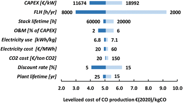
The levelized production costs, as presented in the previous section, are our base case estimates. Most parameters are not fixed values and are better described as a range. To illustrate the dependence of the total production costs on a single parameter, we have performed a sensitivity analysis for each of the routes. The low temperature routes, as well as the tandem route, rely mainly on CAPEX and, as a result, all parameters that are correlated to CAPEX have a substantial impact on the levelized production costs. This is shown for route 1 in Fig. 23. The uncertainty in current CAPEX estimates has a substantial impact on the range of levelized production costs. Our base case value of 5.1€ per kg of CO may reduce to approximately 4€ per kg for our optimistic CAPEX value or increase to more than 6€ per kg if the investment costs approach 19![[thin space (1/6-em)]](https://www.rsc.org/images/entities/char_2009.gif) 000€ per kW. If the amount of full-load hours (FLH) is either doubled or halved compared to our base case of 4000 FLH, the installed capacity also doubles or halves. The production costs almost linearly follow this trend and at nearly full load (8000 FLH), the levelized CO production costs go down to 3.0€ per kg. Currently, in most countries the intermittency of renewable electricity supply results in boundary conditions for the operation of processes to produce renewable products to avoid the use of fossil-based electricity (see also Chapter 4). At some locations or in the future, to drive these processes for more than 4000 FLH seems possible, and, especially as long as CAPEX is a dominant cost factor, this may have a substantial impact on the levelized production costs. The stack lifetime is important to assess the costs associated with maintenance (i.e. stack replacement costs). Our base case value of 40
000€ per kW. If the amount of full-load hours (FLH) is either doubled or halved compared to our base case of 4000 FLH, the installed capacity also doubles or halves. The production costs almost linearly follow this trend and at nearly full load (8000 FLH), the levelized CO production costs go down to 3.0€ per kg. Currently, in most countries the intermittency of renewable electricity supply results in boundary conditions for the operation of processes to produce renewable products to avoid the use of fossil-based electricity (see also Chapter 4). At some locations or in the future, to drive these processes for more than 4000 FLH seems possible, and, especially as long as CAPEX is a dominant cost factor, this may have a substantial impact on the levelized production costs. The stack lifetime is important to assess the costs associated with maintenance (i.e. stack replacement costs). Our base case value of 40![[thin space (1/6-em)]](https://www.rsc.org/images/entities/char_2009.gif) 000 hours is based on PEM electrolyser stacks and improvements (e.g., up to 60
000 hours is based on PEM electrolyser stacks and improvements (e.g., up to 60![[thin space (1/6-em)]](https://www.rsc.org/images/entities/char_2009.gif) 000 hours) have a clear, but limited, positive effect on the production costs. A reduced stack lifetime (e.g., down to 20
000 hours) have a clear, but limited, positive effect on the production costs. A reduced stack lifetime (e.g., down to 20![[thin space (1/6-em)]](https://www.rsc.org/images/entities/char_2009.gif) 000 hours) has, however, a larger negative impact and achieving a certain level of stack lifetime, thus, seems an important development target. The O&M costs are a constant percentage of the CAPEX in our analysis and, as a consequence, their impact is high as long as the investment costs dominate the total production costs. Also, the discount rate directly affects the investment cost component and, because CAPEX is currently so high for LT routes, resembles an important parameter. The plant lifetime influences our CAPEX component in that it is used to calculate the capital recovery factor (ESI, eqn (2)†) and its impact on the production costs remains rather low if the lifetime is at least 20 years.
000 hours) has, however, a larger negative impact and achieving a certain level of stack lifetime, thus, seems an important development target. The O&M costs are a constant percentage of the CAPEX in our analysis and, as a consequence, their impact is high as long as the investment costs dominate the total production costs. Also, the discount rate directly affects the investment cost component and, because CAPEX is currently so high for LT routes, resembles an important parameter. The plant lifetime influences our CAPEX component in that it is used to calculate the capital recovery factor (ESI, eqn (2)†) and its impact on the production costs remains rather low if the lifetime is at least 20 years.
The electricity use and costs are at this stage not so relevant for the levelized CO production costs. Even electricity costs as low as 20€ per MW h do not lead to a substantial cost reduction. The same holds for CO2 costs because varying those from 20 to 150€ per tCO2 only results in a difference in production costs of 0.2€ per kgCO, which is relatively a minimal impact. For routes 2, 3, and 6, the sensitivity analysis tells a nearly identical story as for route 1 and we refer to the ESI for more information (Fig. S6, S7, and S9).†
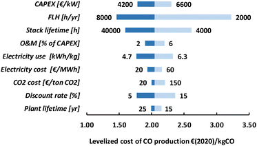
The specific investment costs for our two HT routes are significantly lower compared to the LT routes and the results of our sensitivity analysis for route 4 are presented in Fig. 24 (see Fig. S8 in the ESI for route 5).† When CAPEX is less dominant, the role of other parameters becomes more apparent. Our variation in electricity use has for HT route 4, for instance, a similar influence on the levelized cost of CO production as has our investment costs range. The explored range in feedstock costs (electricity and CO2) provides a more than 10% difference in levelized costs, which is much higher compared to the LT route (<5%).
For all routes, investment costs are an important component as can be expected for low TRL technologies. It is however likely that these costs can be reduced substantially during scale-up and deployment. In the next section, we explore how such cost reductions may influence the competitivity of our routes in the future.
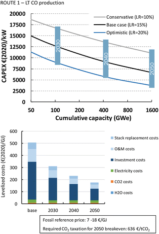
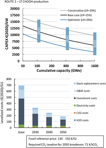
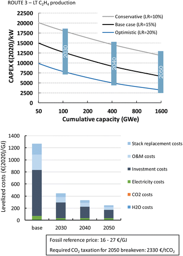
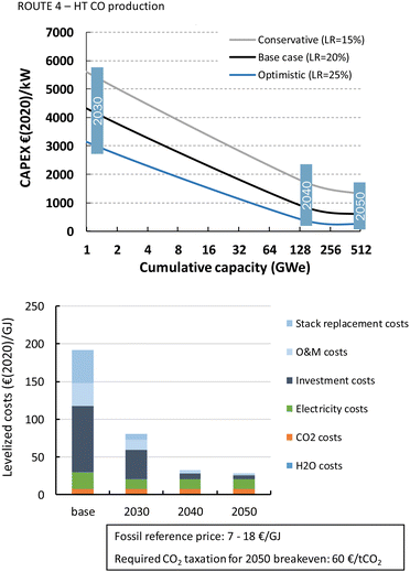
3.4 Cost projections
As indicated in the previous sections, the current costs to electrochemically convert CO2 into products are high compared to fossil-based alternatives. The costs may be reduced substantially thanks to, for instance, learning-by-searching, learning-by-doing, economies-of-scale, and lower material costs. We apply a learning curve analysis on the CAPEX component of our six conversion routes to explore how several of these phenomena affect the future investment costs. The insights from these learning curves are used to project the production costs for 2030, 2040, and 2050, taking into account several performance improvements in the electrochemical conversion processes.Low temperature systems to convert CO2 into products are still at the pilot stage (kW scale systems) and current installed capacity is low (<MW). High temperature processes are slightly further in TRL but their cumulative installed capacity is also low (few MW) because the largest projects are currently developing MW systems. To project their learning curves, we base our initial cumulative experience and learning rate on that of comparable technology. For LT CO2 conversion, the technology is fairly similar to the chlor-alkali electrolytic process. The electrolyser stack, as well as the power electronics and other balance-of-plant equipment, are basically the same. Some pre-treatment and purification steps differ because these have to deal with other starting materials and products. The same manufacturers supply equipment for the chlor-alkali, the electrolytic hydrogen, as well as the electrochemical CO2 conversion industry. This justifies the use of existing experience and learning curve data of electrolytic production of chlor-alkali and hydrogen. To our knowledge, no learning curve has been reported for chlor-alkali investment costs. For electrolytic hydrogen production, several contributions report about a historical learning curve for electrolysers,100–102 and projections of cost reductions based on a learning curve.27,39,88,89 The results and assumptions of these studies have been summarized in Table 17. An important parameter for our projections is the initial cumulative installed capacity on which we base the existing experience because this value determines the amount of novel capacity that has to be installed before another doubling in cumulative capacity is reached. The value varies slightly among the studies but in each case seems to be based on the total capacity of both electrolytic chlor-alkali and hydrogen production systems. For our analysis, we assume that all experience gained in the chlor-alkali, water electrolysis, and PEM fuel cell industries is both part of the historical learning but also for future learning effects. This means that the total cumulative installed capacity for low temperature electrochemical conversion technology represents a substantially higher figure than used in most previous studies. The total production capacity of the chlor-alkali industry is currently around 22 GW and cumulatively approximately 40 GW of capacity (including replacements) has been installed over time. Together with water electrolysis and PEMFC systems, we arrive at an initial CIC of 45 GW for LT electroconversion routes. Historical learning curves for LT electrochemical devices have been reported for water electrolysis and PEM fuel cells (PEMFC).99–101,103,104 The learning rates vary between 16 and 21%. Many of these learning rates are based on the (manufacturing) costs of the system and do not include other costs that contribute to the construction of an entire chemical plant. Several of these other components are more mature as the electrolyser stack and benefit less from learning effects. We therefore apply to the total investment costs a conservative LR range of 10–20% with 15% as base case value.
| Study | Technology | CIC | LR (applied) | Year(s) |
|---|---|---|---|---|
| This study | LT CO2 electroconversion | 45 GW (2020) | 15 ± 5 | 2020–2050 |
| This study | HT CO2 electroconversion | 0.5 GW (2020) | 20 ± 5 | 2020–2050 |
| Rubin et al. 2015 (ref. 98) | Onshore wind | 837 GW (2021)105 | 12 | 1979–2010 |
| ITRPV 2022 (ref. 97) | Solar PV | 972 GW (2021) | 24 | 1976–2021 |
| Schoots et al. 2008 (ref. 99) | LT electrolysis | 15 GW (2006) | 18 ± 13 | 1956–2006 |
| Schmidt et al. 2017 (ref. 100) | LT electrolysis | 20 GW (2014) | 18 ± 6 | 1956–2014 |
| Krishnan et al. 2020 (ref. 101) | LT electrolysis | 20 GW (2016) | 16 ± 6 | 1956–2016 |
| Schoots et al. 2010 (ref. 102) | PEMFC | 0.3 GW (2008) | 21 ± 4 | 1995–2006 |
| Rivera-Tinoco et al. 2012 (ref. 104) | SOFC | 0.05 GW (2009) | 35 | 1986–2009 |
| Wei et al. 2017 (ref. 103) | PEMFC | 0.8 GW (2015) | 18 | 2005–2015 |
| Wei et al. 2017 (ref. 103) | SOFC | 0.1 GW (2015) | ∼0 | 2001–2015 |
| Detz et al. 2018 (ref. 89) | LT electrolysis (AE) | 21 GW (2015) | 18 | 2015–2050 |
| Detz et al. 2018 (ref. 89) | LT electrolysis (PEM) | 0.8 GW (2015, PEMFC) | 21 (PEMFC) | 2015–2050 |
| Detz et al. 2018 (ref. 89) | HT electrolysis | 0.2 GW (2015, SOFC) | 27 (SOFC) | 2015–2050 |
| Bohm et al. 2019 (ref. 39) | LT electrolysis (AE) | 20 GW (2015) | 18 | |
| Bohm et al. 2019 (ref. 39) | LT electrolysis (PEM) | 1 GW (2015) | 18 | |
| Bohm et al. 2019 (ref. 39) | HT electrolysis | 0.1 GW (2015) | 18 | |
| Detz & Weeda 2022 (ref. 88) | Electrolysis | 20 GW (2020) | 9–20 | 2020–2050 |
| IEA, 2021 (ref. 27) | Electrolysis | 0.3 GW (2020) | 15 (stack) | 2020–2050 |
| Calculated in this study | Chlor-alkali | 40 GW (2020) | ||
| Calculated in this study | LT electrolysis | 3.3 GW (2020) |
HT electroconversion systems differ substantially from their LT counterparts. The stacks contain no liquids and consist of solid ceramic materials, while the balance-of-plant equipment has to deal with gases and steam throughput and high process temperatures. We therefore select our starting point based on both SOFC and SOEC technology. The total CIC of such systems is estimated to be approximately 0.5 GW, mainly SOFCs. As far as we know, two learning curve analyses have been reported for SOFC technology, but the learning rates vary significantly from 0 to 35%.103,106 Such a broad range is illustrative of the high uncertainty with which assessment of technologies at an early development stage is typically accompanied. For instance, a lack of markets and competition can reduce the urgency for a manufacturer to produce and sell cheaper systems. We apply for our HT routes a slightly higher LR range compared to the LT systems, of 15–25%, with 20% as the base case value.
The projected learning curves for all our routes are depicted in Fig. 25 to 30. For LT CO production route 1, the total investment costs reduce from currently approximately 11![[thin space (1/6-em)]](https://www.rsc.org/images/entities/char_2009.gif) 700–19
700–19![[thin space (1/6-em)]](https://www.rsc.org/images/entities/char_2009.gif) 000€ per kWel to 3700–11
000€ per kWel to 3700–11![[thin space (1/6-em)]](https://www.rsc.org/images/entities/char_2009.gif) 000€ per kWel after around five doublings in CIC (Fig. 25). If 1.6 TW of LT electrochemical devices has been installed in 2050, our base case projection amounts to 6600€ per kWel, which is nearly a 60% reduction in CAPEX compared to 2020. This cost reduction is through our applied learning curve induced by multiple factors, such as economies-of-scale, manufacturing improvements, and process optimization, among others. We indicate that our specific CAPEX in kWel input and improvements in the power density of the process have a tremendous impact on the output per kWel. This effect has not been investigated separately but the indirect consequence of our analysis implies that it is not straightforward that CAPEX scales linearly down with increasing power density. In other words, we assume that raising the power density goes paired with an increase in CAPEX. Notably, if in reality the power density can be improved without affecting the investment costs, costs may reduce faster as projected here. From the levelized production costs calculations (see above), it became clear that CAPEX resembles the key cost component for our routes. Lower investment costs, thus, have a substantial impact on the levelized production costs, which in our base case scenario reduce from 2020 to 2050 by nearly 65% to 175€ per GJ (1.75€ per kg). A small contribution to the observed cost reduction comes from improvements in energy efficiency (Table 18). In comparison to our fossil benchmark of below 18€ per GJ, these costs are still high. Only with a CO2 tax of at least more than 600€ per tCO2, the production costs of route 1 can reach a breakeven point with the fossil reference price. On the specialty chemicals market with prices around 3€ per kg,107 the LT CO production route might become competitive already in 2030, even without CO2 taxation.
000€ per kWel after around five doublings in CIC (Fig. 25). If 1.6 TW of LT electrochemical devices has been installed in 2050, our base case projection amounts to 6600€ per kWel, which is nearly a 60% reduction in CAPEX compared to 2020. This cost reduction is through our applied learning curve induced by multiple factors, such as economies-of-scale, manufacturing improvements, and process optimization, among others. We indicate that our specific CAPEX in kWel input and improvements in the power density of the process have a tremendous impact on the output per kWel. This effect has not been investigated separately but the indirect consequence of our analysis implies that it is not straightforward that CAPEX scales linearly down with increasing power density. In other words, we assume that raising the power density goes paired with an increase in CAPEX. Notably, if in reality the power density can be improved without affecting the investment costs, costs may reduce faster as projected here. From the levelized production costs calculations (see above), it became clear that CAPEX resembles the key cost component for our routes. Lower investment costs, thus, have a substantial impact on the levelized production costs, which in our base case scenario reduce from 2020 to 2050 by nearly 65% to 175€ per GJ (1.75€ per kg). A small contribution to the observed cost reduction comes from improvements in energy efficiency (Table 18). In comparison to our fossil benchmark of below 18€ per GJ, these costs are still high. Only with a CO2 tax of at least more than 600€ per tCO2, the production costs of route 1 can reach a breakeven point with the fossil reference price. On the specialty chemicals market with prices around 3€ per kg,107 the LT CO production route might become competitive already in 2030, even without CO2 taxation.
| Route | Parameter | 2020 | 2050 |
|---|---|---|---|
| a For LT technology, these improvements come mainly from an improved cell voltage in 2030.28 For HT technology, own calculations indicate a possible reduction of the energy use for the balance-of-plant equipment, mainly for route 4. | |||
| 1 | Energy efficiency | 40% | 56% |
| 2 | Energy efficiency | 26% | 47% |
| 3 | Energy efficiency | 16% | 39% |
| 4 | Energy efficiency | 50% | 90% |
| 5 | Energy efficiency | 82% | 86% |
| 6 | Energy efficiency | 16% | 32% |
The investment cost projection for LT formic acid production (route 2) follows a similar pattern to that for route 1. CAPEX reduces from currently 10![[thin space (1/6-em)]](https://www.rsc.org/images/entities/char_2009.gif) 700–16
700–16![[thin space (1/6-em)]](https://www.rsc.org/images/entities/char_2009.gif) 700€ per kWel to 3400–9700€ per kWel going up in CIC to 1600 GWe (Fig. 26). This has a positive effect on the projected levelized cost as these go down from nearly 700€ per GJ today, to below 200€ per GJ in 2050. Such a cost level is already close to our fossil reference price and, for breakeven, a CO2 taxation of approximately 70€ per tCO2 should be sufficient.
700€ per kWel to 3400–9700€ per kWel going up in CIC to 1600 GWe (Fig. 26). This has a positive effect on the projected levelized cost as these go down from nearly 700€ per GJ today, to below 200€ per GJ in 2050. Such a cost level is already close to our fossil reference price and, for breakeven, a CO2 taxation of approximately 70€ per tCO2 should be sufficient.
The investment cost projection for LT ethylene production (route 3) reduced from an initial 10![[thin space (1/6-em)]](https://www.rsc.org/images/entities/char_2009.gif) 700–16
700–16![[thin space (1/6-em)]](https://www.rsc.org/images/entities/char_2009.gif) 700€/ per Wel to 3400–9700€ per kWel for a CIC of 1600 GWe (Fig. 27). The positive effect of a lower CAPEX on the levelized production costs of ethylene is further enhanced by a higher conversion and energy efficiency of the process. Together these developments result in a cost decline of 80% compared to our current base case costs by 2050. The levelized costs of 250€ per GJ ethylene in 2050 are a factor of ten higher than our fossil reference price. Only with a very high CO2 tax of more than 2300€ per tCO2, which may be unrealistic, a cost-breakeven point can be reached.
700€/ per Wel to 3400–9700€ per kWel for a CIC of 1600 GWe (Fig. 27). The positive effect of a lower CAPEX on the levelized production costs of ethylene is further enhanced by a higher conversion and energy efficiency of the process. Together these developments result in a cost decline of 80% compared to our current base case costs by 2050. The levelized costs of 250€ per GJ ethylene in 2050 are a factor of ten higher than our fossil reference price. Only with a very high CO2 tax of more than 2300€ per tCO2, which may be unrealistic, a cost-breakeven point can be reached.
The specific investment costs for HT CO2 electrochemical conversion (routes 4 and 5) are significantly lower in comparison to LT routes. For CO production, CAPEX ranges currently between 4200 and 6600€ per kWel, which is already close to the 2050 projections for our LT routes. Descending its learning curve, the costs go down rapidly thanks to the relatively high LR of 20% for the base case compared to 15% for our LT routes. We project that around 0.5 TW of cumulative capacity will be installed in 2050. As mentioned, this value includes the installed capacity of solid oxide water electrolysers and fuel cells. In such a scenario, the investment costs reduce to 240–1300€ per kWel (Fig. 28). This CAPEX reduction, together with improvements in energy efficiency and prolonged stack lifetime, results in levelized production costs for CO of 28€ per GJ or 0.28€ per kg in 2050. This is close to the fossil reference price of 7–18€ per GJ and a CO2 tax of 60€ per tCO2 would already induce a point of breakeven.
The investment costs for HT syngas production currently amount to 3000–5400€ per kWel and our projection indicates that costs may go down to 170–1060€ per kWel (Fig. 29). This is the main driver for a significant reduction of the levelized costs to produce syngas via this route towards 2050. In 2050, the dominant cost component is the electricity costs, which represent nearly 60% of the total production costs of 22€ per GJ or 0.53€ per kg. To become competitive with the fossil reference price of 7–18€ per GJ, a CO2 taxation of at least 100€ per tCO2 would be required.
In the tandem process (route 6), first CO2 is converted by a HT system into CO, which is the feed for a LT electrolyser in which ethylene is produced. The current investment costs heavily rely on the costs of the LT system (>95%). This justifies the application of the learning curve parameters for the LT technology to the total investment costs. Our learning curve indicates that costs go down from 12![[thin space (1/6-em)]](https://www.rsc.org/images/entities/char_2009.gif) 300–25
300–25![[thin space (1/6-em)]](https://www.rsc.org/images/entities/char_2009.gif) 700€ per kWel now to 5300–11
700€ per kWel now to 5300–11![[thin space (1/6-em)]](https://www.rsc.org/images/entities/char_2009.gif) 100€ per kWel in 2050 (Fig. 30). For our base case in 2050, this means that investment costs still dominate the ethylene production costs, which reduce by more than a factor 4 to 374€ per GJ or nearly 18€ per kg ethylene. In our projections, any improvements in selectivity and efficiency of the process are excluded. These developments would further reduce production costs because of lower energy usage and potentially less required capacity to produce a certain amount of ethylene. Compared to the fossil reference price of 16–27€ per GJ, such a cost is very high and only with exceptionally high CO2 pricing (>3600€ per tCO2) a point of breakeven can be reached.
100€ per kWel in 2050 (Fig. 30). For our base case in 2050, this means that investment costs still dominate the ethylene production costs, which reduce by more than a factor 4 to 374€ per GJ or nearly 18€ per kg ethylene. In our projections, any improvements in selectivity and efficiency of the process are excluded. These developments would further reduce production costs because of lower energy usage and potentially less required capacity to produce a certain amount of ethylene. Compared to the fossil reference price of 16–27€ per GJ, such a cost is very high and only with exceptionally high CO2 pricing (>3600€ per tCO2) a point of breakeven can be reached.
4 Greenhouse gas emission performance
The prospect of novel technologies to produce fuels and chemicals depends largely on their competitiveness with conventional pathways. We indicated in the previous chapters that if learning-by-doing proceeds as expected, some CO2 electrochemical conversion routes may become economically competitive with alternative approaches based on fossil resources. Notably, this only seems possible if sufficient CO2 taxation is in play, ranging from 60 to more than an unrealistically high 3600€ per tCO2. It will be important that the GHG emissions associated with our routes are significantly lower compared to their fossil reference. Here, we calculate the CO2 emissions for each of the six routes by comparing the indirect emissions from electricity use of both the CO2 capture technology as well as the electroconversion (and purification) technology (Fig. 31). This can serve as a best-case orientation because it doesn't consider other emissions, for instance from construction or equipment manufacturing. The emission factor of the electricity supply clearly affects the total emissions of the route (Fig. 32). Our routes start from CO2 as feedstock, without taking into account (for the cost analysis) the origin of this CO2. To supply CO2 as a feedstock for our routes, energy is required for the capture, which can be either from a point source or from the air.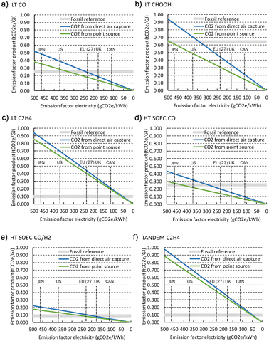 | ||
| Fig. 32 Emissions from electricity use for the six electrochemical CO2 conversion routes. The vertical dotted lines indicate the emission factor of the grid in a specific country/region in 2020. | ||
To indicate the difference in energy regarding point source capture and DAC, we show both scenarios, i.e., the emission factor of the product based on either point source capture (green lines) or DAC (blue lines). The energy use of point source capture depends on the type of point source and gas stream and, thus, varies significantly. We take a value (0.3 MW h per tCO2) at the lower side of the reported figures and assume that this energy can be supplied as electricity, either direct or via electric heating.108,109 For DAC, we use similar assumptions, but the electricity use is determined to be at the high end of the reported range (2.0 MW h per tCO2).110 By this, we cover more or less the entire range of emissions related to the electricity use for our CO2 supply. The results are compared with the emissions related to the fossil reference pathway, which is based on average 100 year global warming potential values from the SimaPro database. In Fig. 32, the emission factor of the products of all routes (routes 1–6: a–f) has been displayed versus the emission factor of the electricity that is used for the process.
The LT route to produce CO can achieve similar emissions as the fossil reference when the emission factor of the grid is less than approximately 350 gCO2e per kW h, which is currently the case in several countries, such as the United Kingdom (UK), Canada (CAN), and in the European Union (EU). To become a meaningful route to produce renewable fuels and chemicals, the emission factor of the products should, however, be significantly lower in comparison to fossil-based alternatives. European regulation for instance states that “the greenhouse gas emissions savings from the use of renewable liquid and gaseous transport fuels of non-biological origin (RFNBO's) shall be at least 70%”.111 To reach such a level of avoided emissions, the grid emission factor should be below 100 gCO2e per kW h for route 1. For formic acid production (route 2), the emission factor of the fossil reference is rather high and breakeven emissions can be realized with a grid emission of 500 gCO2e per kW h, while a 70% reduction is realized with electricity that is generated with emissions of maximal 150 gCO2e per kW h. In several countries, thanks to an increasing share of renewable electricity supply, the average grid emission factor is already approaching such a value and would thus afford the electrochemical production of these products at full annual capacity. The levelized costs would reduce from our base case value of 3.7€ per kg for 4000 FLH to 2.2€ per kg for 8000 FLH. A totally different situation occurs for production routes 3 and 6 because the fossil reference emissions for ethylene production are relatively low and the electricity use of the electrochemical process is high. Only with a very low grid emission factor of around 50 gCO2e per kW h, a product emission factor is obtained that is similar to the fossil reference. A >70% reduction target is within reach, but the grid emission factor should be close to zero.
The HT route 4 to produce CO is more efficient than the LT alternative and requires less electricity usage. The emission factor of the grid can be nearly 450 gCO2e per kW h for this route based on point source CO2 to achieve an emission breakeven point with the fossil reference. To realize >70% GHG savings, the difference between routes 1 and 4 becomes smaller in absolute terms and emissions from the grid may amount to 125 gCO2e per kW h or 25 gCO2e per kW h more than for route 1. Syngas contains less carbon per GJ of product compared to pure CO and its associated emission factor is analogously lower, also for the fossil reference. With grid emissions below 250 gCO2e per kW h, the electrochemical pathway can compete in emissions with the fossil-based alternative. From around 70 gCO2e per kW h and lower, substantial GHG savings (>70%) can be reached, purely based on the electricity use of the process. Background emissions throughout the entire supply chains and other environmental aspects are not (fully) analysed and may have an impact on our preliminary conclusions on the competitivity of these routes with fossil reference pathways. A full life-cycle assessment can provide more detailed insights into these aspects but is not part of this study.
5 Knowledge gaps and research directions
Here, we discuss the challenges and knowledge gaps that we identified in our study. We also proffer recommendations for further research. Below we list specific technical challenges to be addressed for each technology and for the processes in general.5.1 Low-temperature electrochemical CO2 conversion routes
![[thin space (1/6-em)]](https://www.rsc.org/images/entities/char_2009.gif) 000 h) at high current densities and efficiencies, and low cell voltage. To achieve this, also the problems of carbonate precipitation at the cathode should be solved (as stated by Küngas, 2020 and Stephens et al., 2022).30,112. Also, the novel LT CO electroconversion from the tandem route (route 6) is gaining increasing attention amongst researchers, and the efficiency and selectivity are expected to improve with catalyst, electrode and material development. However, it is uncertain whether LT CO electroconversion will reach the same performance as the projected LT CO2 electrolysis goals for the next decade postulated in the roadmap by Nørskov et al.28
000 h) at high current densities and efficiencies, and low cell voltage. To achieve this, also the problems of carbonate precipitation at the cathode should be solved (as stated by Küngas, 2020 and Stephens et al., 2022).30,112. Also, the novel LT CO electroconversion from the tandem route (route 6) is gaining increasing attention amongst researchers, and the efficiency and selectivity are expected to improve with catalyst, electrode and material development. However, it is uncertain whether LT CO electroconversion will reach the same performance as the projected LT CO2 electrolysis goals for the next decade postulated in the roadmap by Nørskov et al.28
The best state-of-the-art lifetime data for LT CO2 electrolysis (for CO production) lifetime are ca. 5000 h at low current densities (500 A m−2) and small scale (10 cm2).30 It is therefore important to understand that the LT CO2 electrolysis process is a technology under development, and a special R&D emphasis on ensuring long-term stability at high current densities (5000–10![[thin space (1/6-em)]](https://www.rsc.org/images/entities/char_2009.gif) 000 A m−2) is critical to make this concept industrially feasible. Kibria et al. stated that the necessary lifetime to obtain a feasible business case for LT CO2 electrolysis should likely be higher than 80
000 A m−2) is critical to make this concept industrially feasible. Kibria et al. stated that the necessary lifetime to obtain a feasible business case for LT CO2 electrolysis should likely be higher than 80![[thin space (1/6-em)]](https://www.rsc.org/images/entities/char_2009.gif) 000 h.114
000 h.114
By selecting a sensible anodic product that can easily be assimilated by the CCU value chain, the economic feasibility drastically improves.119,123 An example of this strategy is the electrochemical co-production of CO and Cl2 in equimolar amounts, the combination of which makes the precursor mixture for phosgene, a key intermediate for plastic and rubber manufacturing.124 Also other chemicals, such as glycerol, can be oxidized at the anode to reduce the energy consumption and increase the product value.125 Despite its potential economic advantages, the implementation of alternative anodic reactions to the OER is less pursued due to the: (1) low cost of water as reactant for the OER; (2) simplicity of disposing O2 to the atmosphere instead of implementing costly purification strategies for the alternative anodic product; and (3) compatibility of the OER with intended CO2 reduction reaction systems.126
5.2 High-temperature electrochemical CO2 conversion routes
5.3 General aspects for electrochemical CO2 conversion routes
![[thin space (1/6-em)]](https://www.rsc.org/images/entities/char_2009.gif) :
:![[thin space (1/6-em)]](https://www.rsc.org/images/entities/char_2009.gif) CO = 2
CO = 2![[thin space (1/6-em)]](https://www.rsc.org/images/entities/char_2009.gif) :
:![[thin space (1/6-em)]](https://www.rsc.org/images/entities/char_2009.gif) 1). The application in which the syngas is applied determines the required composition of produced syngas from the SOEC system outlet. Hence, the ratio of steam and CO2 feedstock must be changed to obtain a syngas with a specified CO/H2 ratio. Moreover, in the case of syngas, separation technology costs for CO/CO2/H2 depend strongly on the intended end-use of the product.
1). The application in which the syngas is applied determines the required composition of produced syngas from the SOEC system outlet. Hence, the ratio of steam and CO2 feedstock must be changed to obtain a syngas with a specified CO/H2 ratio. Moreover, in the case of syngas, separation technology costs for CO/CO2/H2 depend strongly on the intended end-use of the product.
6 Conclusions
This review and analysis shows that several electrochemical technologies are available to convert CO2 into different products. All routes are currently significantly more expensive in comparison with fossil-based approaches, but stringent climate targets in combination with technology development may in the future favour renewable alternative approaches. The chlor-alkali process, as an example of a mature electrochemical process, can function as a starting point for reference and potential technology developments, especially for LT technology. The LT routes seem to be mainly based on membrane-type electrolyser systems and can benefit from developments in water electrolysis and fuel cell applications, e.g. PEM technology. HT systems are less comparable to membrane technology and are better compared with solid state fuel cell technology, such as SOFC and MCFC. Solid oxide technology seems most advanced in technology readiness and applied in larger scale CO2 electroconversion demonstrators. These HT systems operate at a relatively high power density, which is comparable to HT steam electrolysis. The investment costs per unit output of HT systems are significantly lower than those of their LT counterparts.Besides this current advantage in investment costs, the projected costs also reduce faster for the HT CO2 conversion routes. This is mainly because in our learning curve analysis the assumed LR, which is based on solid oxide fuel cell technology, is slightly higher compared to LT technology for which the LR is based on LT water electrolysis, and the initial cumulative installed capacity of HT technology is relatively low, which makes relative capacity additions more likely to occur faster. The economic performance of all routes is mainly determined by the CAPEX component and thanks to steep learning of the HT pathways, these routes are likely first to reach break-even levelized production cost in comparison to the fossil reference. LT electrolysis processes still need a substantial reduction in investment costs to achieve break-even.
All electrochemical production routes to produce CO, formic acid, and syngas avoid or can soon avoid CO2 emissions when compared to fossil reference processes. CO2 taxation can therefore play a substantial role in the competitivity of electrochemical CO2 conversion routes. In our base case projections, we find that for CO, formic acid, and syngas production, CO2 taxation should range between at least 60 and 636€ per tCO2 to break even with the fossil reference price. The most promising to reach break-even costs are LT formic acid production (CO2 tax of 72€ per tCO2) and HT CO production (CO2 tax of 60€ per tCO2). A higher CO2 penalty would be required if the electricity that is used in the electroconversion routes is accompanied by an emission factor greater than zero. For ethylene production, saving GHG emissions by the electrochemical routes (3 and 6) becomes difficult if the efficiency and power density cannot be substantially improved without raising the investment costs. Our projections indicate that only with a CO2 taxation of more than 2000€ per tCO2 these routes may become competitive with the current fossil-based benchmark, which is not realistically feasible.
The early development stage of the investigated technologies also proffers opportunity for improvements and innovation that can drastically increase the technological performance. Research gaps are identified at various levels: materials, catalysts, electrodes, lifetime and associated maintenance costs of the active materials. Purification of both the feedstock and product, and downstream processing costs depend on the feedstock and product requirements. The early-stage research often does not focus on these up- and downstream processes and further study is necessary. Pilot projects demonstrating the entire product chain, from the industrial or atmospheric CO2 source to the final product, can aid in the accurate assessment of the performance, total investment costs, and operating and maintenance costs in an industrial environment. More development and investments are deemed necessary to ensure technological learning effects and cost reductions of electrochemical CO2 conversion routes. An advantage of these specific processes is that they can benefit from experience obtained in comparable technologies, such as water electrolysers and fuel cells.
Author contributions
RJD, AJK, and JK: conceptualization. RJD and AJK: methodology. RJD, CJF, CSM, MS, and MVS: investigation and analysis. RJD, CJF, AJK, CSM, and MVS: writing—original draft. RJD: produced final manuscript. RJD, CJF, AJK, JK, CSM, MS, and MVS: discussed and reviewed the results. RJD, CJF, CSM, and MVS: visualization. AJK and JK: project management and acquisition. All authors contributed to the article and approved the submitted version.Conflicts of interest
There are no conflicts to declare.Acknowledgements
The authors acknowledge T. Manders, G. J. Kramer, and S. Krishnan for stimulating discussions that helped improve the quality of our study. We acknowledge the IEA Greenhouse Gas R&D Programme for the funding of this project.References
- P. Friedlingstein, M. W. Jones, M. O'Sullivan, R. M. Andrew, D. C. E. Bakker, J. Hauck, C. Le Quéré, G. P. Peters, W. Peters, J. Pongratz, S. Sitch, J. G. Canadell, P. Ciais, R. B. Jackson, S. R. Alin, P. Anthoni, N. R. Bates, M. Becker, N. Bellouin, L. Bopp, T. T. T. Chau, F. Chevallier, L. P. Chini, M. Cronin, K. I. Currie, B. Decharme, L. Djeutchouang, X. Dou, W. Evans, R. A. Feely, L. Feng, T. Gasser, D. Gilfillan, T. Gkritzalis, G. Grassi, L. Gregor, N. Gruber, Ö. Gürses, I. Harris, R. A. Houghton, G. C. Hurtt, Y. Iida, T. Ilyina, I. T. Luijkx, A. K. Jain, S. D. Jones, E. Kato, D. Kennedy, K. Klein Goldewijk, J. Knauer, J. I. Korsbakken, A. Körtzinger, P. Landschützer, S. K. Lauvset, N. Lefèvre, S. Lienert, J. Liu, G. Marland, P. C. McGuire, J. R. Melton, D. R. Munro, J. E. M. S. Nabel, S.-I. Nakaoka, Y. Niwa, T. Ono, D. Pierrot, B. Poulter, G. Rehder, L. Resplandy, E. Robertson, C. Rödenbeck, T. M. Rosan, J. Schwinger, C. Schwingshackl, R. Séférian, A. J. Sutton, C. Sweeney, T. Tanhua, P. P. Tans, H. Tian, B. Tilbrook, F. Tubiello, G. van der Werf, C. Wada, R. Wanninkhof, A. Watson, D. Willis, A. J. Wiltshire, W. Yuan, C. Yue, X. Yue, S. Zaehle and J. Zeng, Earth System Science Data Discussion [preprint], Global Carbon Budget, 2021, DOI:10.5194/essd-2021-386.
- R. J. Detz and B. van der Zwaan, Energy Policy, 2019, 133, 110938, DOI:10.1016/j.enpol.2019.110938.
- IEAGHG, CO2 as a Feedstock: Comparison of CCU Pathways, IEAGHG Technical Report, 2021-02, 2021, Retrieved from: https://www.ieaghg.org/ Search PubMed.
- International Energy Agency (IEA), Putting CO2 to use. Creating value from emissions, 2019, Retrieved from: https://www.iea.org Search PubMed.
- International Energy Agency (IEA), Energy Technology Perspectives 2020. Special Report on Carbon Capture, Utilisation and Storage, 2020, Retrieved from: https://www.iea.org Search PubMed.
- Y. Jiang, M. Su, Y. Zhang, G. Zhan, Y. Tao and D. Li, Int. J. Hydrogen Energy, 2013, 38, 3497–3502 CrossRef CAS.
- C. Li, T. Wang, B. Liu, M. Chen, A. Li, G. Zhang, M. Du, H. Wang, S. F. Liu and J. Gong, Energy Environ. Sci., 2019, 12, 923–928, 10.1039/C8EE02768D.
- S.-F. Ng, J. Jie Foo and W.-J. Ong, InfoMat, 2022, 4(1), e12279 CrossRef CAS.
- IEAGHG, CO2 Utilisation: Hydrogenation Pathways, IEAGHG Technical Report, 2021-03, 2021, Retrieved from: https://www.ieaghg.org/ Search PubMed.
- S. Lu, Y. Shi, N. Meng, S. Lu, Y. Yu and B. Zhang, Cell Rep. Phys. Sci., 2020, 1(11), 100237 CrossRef.
- A. Sedighian Rasouli, X. Wang, J. Wicks, G. Lee, T. Peng, F. Li, C. McCallum, C.-T. Dinh, A. H. Ip, D. Sinton and E. H. Sargent, ACS Sustainable Chem. Eng., 2020, 8(39), 14668–14673 CrossRef CAS.
- J. Albo, A. Sáez, J. Solla-Gullón, V. Montiel and A. Irabien, Appl. Catal., B, 2015, 176–177, 709–717, DOI:10.1016/j.apcatb.2015.04.055.
- K. Nakata, T. Ozaki, C. Terashima, A. Fujishima and Y. Einaga, Angew. Chem., Int. Ed., 2014, 53(3), 871–874, DOI:10.1002/anie.201308657.
- M. König, S.-H. Lin, J. Vaes, D. Pant and E. Klemm, Faraday Discuss., 2021, 230, 360–374, 10.1039/D0FD00141D.
- D. Karapinar, C. E. Creissen, J. Guillermo Rivera de la Cruz, M. W. Schreiber and M. Fontecave, ACS Energy Lett., 2021, 6(2), 694–706 CrossRef CAS.
- X. Wang, P. Ou and A. Ozden, et al. , Nat. Energy, 2022, 7, 170–176, DOI:10.1038/s41560-021-00967-7.
- T. F. O'Brien, T. V. Bommaraju and F. Hine, Handbook of Chlor-Alkali Technology, Springer, New York, 2005, vol. 1 Search PubMed.
- J. Crook and A. Mousavi, Environ. Forensics, 2016, 17(3), 211–217, DOI:10.1080/15275922.2016.1177755.
- T. Brinkmann, G. Giner Santonja, F. Schorcht, S. Roudier and L. Delgado Sancho, Best Available Techniques Reference Document for the Production of Chlor-Alkali, 2014, DOI:10.2791/13138.
- Eurochlor, Personal Communication with Ton Manders (on 29-04-2022), 2022 Search PubMed.
- Thyssenkrupp, Chlor-Alkali Solutions, 2022, Retrieved from: https://thyssenkrupp-nucera.com/chlor-alkali-solutions/ Search PubMed.
- Eurochlor, The Electrolysis process and the real costs of production, 2018, Retrieved from: https://www.eurochlor.org/wp-content/uploads/2019/04/12-electrolysis_production_costs.pdf Search PubMed.
- International Energy Agency (IEA), The Future of Hydrogen. Seizing today's opportunities, 2019, Retrieved from: https://www.iea.org Search PubMed.
- Thyssenkrupp, Chlor-Alkali electrolysis plants. Superior membrane process, 2015, Retrieved from: https://www.thyssenkrupp-industrial-solutions-rus.com/assets/pdf/TKIS_Chlor-Alkali_Electrolysis.pdf Search PubMed.
- T. Smolinka, N. Wiebe, P. Sterchele, A. Palzer, F. Lehner, M. Jansen, S. Kiemel, R. Miehe, S. Wahren and F. Zimmermann, Studie IndWEDe, Industrialisierung der Wasserelektrolyse in Deutschland: Chancen und Herausforderungen für nachhaltigen Wasserstoff für Verkehr, Nationale Organisation Wasserstoff- und Brennstoffzellentechnologie – NOW GmbH, Strom und Wärme, 2018 Search PubMed.
- International Renewable Energy Agency (IRENA), Green Hydrogen Cost Reduction: Scaling up Electrolysers to Meet the 1.5 °C Climate Goal, International Renewable Energy Agency, Abu Dhabi, 2020, Retrieved from: https://www.irena.org/ Search PubMed.
- International Energy Agency (IEA), Net Zero by 2050 - A Roadmap for the Global Energy Sector, 2021, Retrieved from: https://www.iea.org Search PubMed.
- J. K. Nørskov, A. Latimer and C. F. Dickens, Research needs towards sustainable production of fuels and chemicals, 2019, Retrieved from: https://www.energy-x.eu/research-needs-report/ Search PubMed.
- Siemens, Rheticus: World’s-first-automated-CO2-electrolyzer, Siemens Energy Global, 2020, Retrieved from: https://www.siemens-energy.com Search PubMed.
- R. Küngas, J. Electrochem. Soc., 2020, 167(4), 044508, DOI:10.1149/1945-7111/ab7099.
- K. Yang, M. Li, S. Subramanian, M. A. Blommaert, W. A. Smith and T. Burdyny, ACS Energy Lett., 2021, 6(12), 4291–4298, DOI:10.1021/acsenergylett.1c02058.
- D. W. Keith, G. Holmes, D. S. Angelo and K. Heidel, Joule, 2018, 2(8), 1573–1594, DOI:10.1016/j.joule.2018.05.006.
- Air Products, 2022, Retrieved from: https://www.airproducts.com/-/media/airproducts/files/en/900/900-13-100-us-carbon-monoxide-safetygram-19.pdf Search PubMed.
- Z. Liu, H. Yang, R. Kutz and R. I. Masel, J. Electrochem. Soc., 2018, 165(15), J3371–J3377, DOI:10.1149/2.0501815jes.
- R. Tichler, H. Böhm, A. Zauner, S. Goers, P. Kroon and S. Schirrmeister, Innovative large-scale energy storage technologies and Power-to-Gas concepts after optimization. Report on experience curves and economies of scale, 2018, Retrieved from: https://www.storeandgo.info/fileadmin/downloads/deliverables_2019/20190801-STOREandGO-D7.5-EIL-Report_on_experience_curves_and_economies_of_scale.pdf Search PubMed.
- M. Jouny, W. Luc and F. Jiao, Ind. Eng. Chem. Res., 2018, 57(6), 2165–2177, DOI:10.1021/acs.iecr.7b03514.
- A. Paturska, M. Repele and G. Bazbauers, Energy Procedia, 2015, 72, 71–78, DOI:10.1016/j.egypro.2015.06.011.
- A. Patonia and R. Poudineh, Cost-competitive green hydrogen: how to lower the cost of electrolysers?, 2022, Retrieved from: https://www.oxfordenergy.org/ Search PubMed.
- H. Böhm, S. Goers and A. Zauner, Int. J. Hydrogen Energy, 2019, 44(59), 30789–30805, DOI:10.1016/j.ijhydene.2019.09.230.
- A. Mayyas, M. Ruth, B. Pivovar, G. Bender and K. Wipke, Manufacturing Cost Analysis for Proton Exchange Membrane Water Electrolyzers, 2019, https://doi.org/NREL/TP-6A20-72740 Search PubMed.
- E. Schuler, M. Demetriou, N. R. Shiju and G. J. M. Gruter, ChemSusChem, 2021, 14(18), 3636–3664, DOI:10.1002/cssc.202101272.
- M. Ramdin, A. R. T. Morrison, M. De Groen, R. van Haperen, R. De Kler, E. Irtem, A. T. Laitinen, L. J. P. van den Broeke, T. Breugelmans, J. P. M. Trusler, W. de Jong and T. J. H. Vlugt, Ind. Eng. Chem. Res., 2019, 58(51), 22718–22740, DOI:10.1021/acs.iecr.9b03970.
- OCEAN, Oxalic acid from CO2 using Electrochemistry At demonstratioN scale|SPIRE, 2022, Retrieved from: https://aspire2050.eu Search PubMed.
- E2c, Electrons to high value Chemical products|2 Mers Seas Zeeën, 2022, Retrieved from: https://interreg2seas.eu Search PubMed.
- Q. Zhu, Clean Energy, 2019, 3(2), 85–100, DOI:10.1093/ce/zkz008.
- H. Yang, J. J. Kaczur, S. D. Sajjad and R. I. Masel, J. CO2 Util., 2017, 20, 208–217, DOI:10.1016/j.jcou.2017.04.011.
- H. Yang, J. J. Kaczur, S. D. Sajjad and R. I. Masel, J. CO2 Util., 2020, 42, 101349, DOI:10.1016/j.jcou.2020.101349.
- SELECT CO2, 2022, Retrieved from: https://selectco2.eu Search PubMed.
- Energiforskning, 2022, Retrieved from: https://energiforskning.dk/projekter/electrochemical-co2-reduction-to-ethylene-industrial-applications Search PubMed.
- C. M. Gabardo, C. P. O'Brien, J. P. Edwards, C. McCallum, Y. Xu, C. T. Dinh, J. Li, E. H. Sargent and D. Sinton, Joule, 2019, 3(11), 2777–2791, DOI:10.1016/j.joule.2019.07.021.
- J. Sisler, S. Khan, A. H. Ip, M. W. Schreiber, S. A. Jaffer, E. R. Bobicki, C. T. Dinh and E. H. Sargent, ACS Energy Lett., 2021, 6(3), 997–1002, DOI:10.1021/acsenergylett.0c02633.
- NIH, 2022, Retrieved from: https://Ethylene-Some-Industrial-Chemicals-NCBI-Bookshelf-(nih.gov).
- X. Wang, J. Ferreira de Araújo, W. Ju, A. Bagger, H. Schmies, S. Kühl, J. Rossmeisl and P. Strasser, Nat. Nanotechnol., 2019, 14, 1063–1070 CrossRef CAS PubMed.
- C. T. Dinh, T. Burdyny, G. Kibria, A. Seifitokaldani, C. M. Gabardo, F. P. G. de Arquer, A. Kiani, J. P. Edwards, P. De Luna, O. S. Bushuyev, C. Zou, R. Quintero-Bermudez, Y. Pang, D. Sinton and E. H. Sargent, Science, 2018, 787, 783–787 CrossRef PubMed.
- A. Hauch, R. Küngas, P. Blennow, A. B. Hansen, J. B. Hansen, B. V. Mathiesen and M. B. Mogensen, Science, 2020, 370(186), eaba6118, DOI:10.1126/science.aba6118.
- S. C. Singhal, WIREs Energy and Environment, 2014, 3(2), 179–194, DOI:10.1002/wene.96.
- J. D. Duhn, Development of Highly Efficient Solid Oxide Electrolyzer Cell Systems. Technical University of Denmark, 2017, Retrieved from: https://orbit.dtu.dk/en/publications/development-of-highly-efficient-solid-oxide-electrolyzer-cell-sys Search PubMed.
- R. Küngas, P. Blennow, T. Heiredal-Clausen, T. Holt Nørby, J. Rass-Hansen, J. B. Hansen and P. G. Moses, ECS Trans., 2019, 91, 215 CrossRef.
- F. Kasuya and T. Tsuji, Gas Sep. Purif., 1991, 5(4), 242–246 CrossRef CAS.
- S. Foit, L. Dittrich, T. Duyster, I. Vinke, R. Eichel and L. de Haart, Processes, 2020, 8(11), 1390 CrossRef CAS.
- Hydrogen Europe, Strategic Research and Innovation Agenda, 2020, Retrieved from: https://www.clean-hydrogen.europa.eu/about-us/key-documents/strategic-research-and-innovation-agenda_en Search PubMed.
- European Commission, Communication from the Commission to the European Parliament, the Council, the European Economic and Social Committee and the Committee of the Regions, 2020 Search PubMed.
- NewSoc, Next Generation of Solid Oxide Fuel Cell and Electrolysis Technology, 2022, Retrieved from: https://Home-NewSoc-English Search PubMed.
- Clean Hydrogen Joint Undertaking (CHJU), Strategic Research and Innovation Agenda 2021 – 2027, 2021, p. 153 Search PubMed.
- Ulrik Frøhlke, Haldor Topsoe to build large-scale SOEC electrolyzer manufacturing facility to meet customer needs for green hydrogen production, 2021, Retrieved from: https://blog.topsoe.com/haldor-topsoe-to-build-large-scale-soec-electrolyzer-manufacturing-facility-to-meet-customer-needs-for-green-hydrogen-production Search PubMed.
- M. Riegraf, D.-M. Amaya-Duenas, A. Surrey and R. Costa, Evaluation of the Stability of Ni/CGO-Based Electrolyte Supported Cells in Co-electrolysis, 12th European SOFC & SOE Forum, B0504, 2016 Search PubMed.
- A. Hauch, M. L. Traulsen, R. Küngas and T. L. Skafte, J. Power Sources, 2021, 506, 230108 CrossRef CAS.
- Sunfire, 2021, Retrieved from: https://www.sunfire.de/files/sunfire/images/content/Produkte_Technologie/factsheets/Sunfire-SynLink_FactSheet.pdf Search PubMed.
- A. Masini, T. Strohbach, F. Siska, Z. Chlup and I. Slouhy, Materials, 2019, 12, 306 CrossRef CAS PubMed.
- Sunfire, 2022, Retrieved from: https://webflow.com Search PubMed.
- Sunfire, 2022, Retrieved from: https://SynLink Search PubMed.
- Eco, 2019, Retrieved from: https://eco-soec-project Search PubMed.
- Kopernikus, 2019, Retreived from: https://Kopernikus-Projekte:Kopernikus-Project:P2X Search PubMed.
- N. e-fuel, 2022, Retrieved from: https://norsk-e-fuel.com Search PubMed.
- MegaSyn, 2022, Retreived from: https://www.fch.europa.eu Search PubMed.
- F. P. F. van Berkel, C. J. Ferchaud, O. Partenie, M. J. G. Linders and Y. C. van Delft, ECS Trans., 2021, 103(1), 591–602 CrossRef CAS.
- O. Posdziech, Production of Renewable Hydrogen and Syngas via High-Temperature Electrolysis, Presentation Sunfire on Heat-To-Fuel Interfaces to Advanced Power-To-Gas and Power-To-Liquids Technologies, 2021, https://e-fuels Search PubMed.
- L. Hu, Molten Carbonate Fuel Cells for Electrolysis, Doctoral Thesis of KTH Royal Institute of Technology, 2016, ISSN 1654-1081, ISBN 978-91-7595-928-3 Search PubMed.
- Fuel Cell Energy, MCFC system product data sheet, 2022, Retreived from: https://www.fuelcellenergy.com/ Search PubMed.
- POSCO, POSCO Energy Website – Fuel Cell Development, 2022, Retreived from: https://posco-energy-Products Search PubMed.
- R. Bove, A. Moreno and S. McPhail, International Status of Molten Carbonate Fuel Cell (MCFC) Technology, EUR 23363 EN, European Commission JRC44203, Luxembourg (Luxembourg), 2008 Search PubMed.
- M. Jouny, W. Luc and F. Jiao, Nat. Catal., 2018, 1(10), 748–755, DOI:10.1038/s41929-018-0133-2.
- M. Jouny, G. S. Hutchings and F. Jiao, Nat. Catal., 2019, 2(12), 1062–1070, DOI:10.1038/s41929-019-0388-2.
- D. S. Ripatti, T. R. Veltman and M. W. Kanan, Joule, 2019, 3(1), 240–256, DOI:10.1016/j.joule.2018.10.007.
- H. J. Lang, Chem. Eng., 1948, 55, 112 CAS.
- Y. A. Wain, PM World J., 2014, 3, 10 Search PubMed.
- Hydrohub Innovation Program, A One-GigaWatt Green-Hydrogen Plant. Advanced Design and Total Installed-Capital Costs, 2022, Retrieved from: https://ispt.eu/news/new-report-gigawatt-green-hydrogen-plant-advanced-design-and-total-installed-capital-costs/ Search PubMed.
- G. Glenk and S. Reichelstein, Nat. Energy, 2019, 4, 216–222 CrossRef CAS.
- R. Detz and M. Weeda, Projections of Electrolyzer Investment Cost Reduction through Learning Curve Analysis, TNO 2022 P10111, 2022, Retrieved from: https://energy.nl/wp-content/uploads/tno-2022-p10111_detzweeda_projections-of-electrolyzer-investment-cost-reduction-through-learning-curve-analysis.pdf Search PubMed.
- R. J. Detz, J. N. H. Reek and B. C. C. van der Zwaan, Energy Environ. Sci., 2018, 11(7), 1653–1669 RSC.
- J. Nyári, M. Magdeldin, M. Larmi, M. Järvinen and A. Santasalo-Aarnio, J. CO2 Util., 2020, 39, 101166, DOI:10.1016/j.jcou.2020.101166.
- R. J. Detz and B. van der Zwaan, J. Energy Chem., 2022, 71, 507–513 CrossRef CAS.
- Methanex, 2022, Retreived from: https://Pricing|Methanex-Corporation Search PubMed.
- ChemAnalist, 2022, Retrieved from: https://Formic-Acid-Prices-Price-Pricing-News|ChemAnalyst Search PubMed.
- ChemAnalist, 2022, Retrieved from: https://Ethylene-Prices-News-Market-Analysis|ChemAnalyst Search PubMed.
- A. McDonald and L. Schrattenholzer, Energy Policy, 2001, 29, 255–261 CrossRef.
- F. Ferioli, K. Schoots and B. C. C. van der Zwaan, Energy Policy, 2009, 37, 2525–2535 CrossRef.
- International Technology Roadmap for Photovoltaic (ITRPV), 2022, Retrieved from: https://www.vdma.org/international-technology-roadmap-photovoltaic Search PubMed.
- E. S. Rubin, I. M. L. Azevedo, P. Jaramillo and S. Yeh, Energy Policy, 2015, 86, 198–218 CrossRef.
- K. Schoots, F. Ferioli, G. J. Kramer and B. C. C. van der Zwaan, Int. J. Hydrogen Energy, 2008, 33, 2630–2645 CrossRef CAS.
- O. Schmidt, A. Hawkes, A. Gambhir and I. Staffell, Nat. Energy, 2017, 2, 17110 CrossRef.
- S. Krishnan, M. Fairlie, P. Andres, T. de Groot and G. J. Kramer, Technological Learning in the Transition to a Low-Carbon Energy System, Conceptual Issues, Empirical Findings, and Use in Energy Modeling, Chapter 10: Power to gas (H2): alkaline electrolysis, 2020, pp. 165–187 Search PubMed.
- K. Schoots, G. J. Kramer and B. C. C. van der Zwaan, Energy Policy, 2010, 38, 2887–2897 CrossRef.
- M. Wei, S. J. Smith and M. D. Sohn, App. Energy, 2017, 191, 346–357 CrossRef.
- Global Wind Energy Council, Global Wind Report 2022, 2022, Retrieved from: https://gwec.net/global-wind-report-2022/ Search PubMed.
- R. Rivera-Tinoco, K. Schoots and B. C. C. van der Zwaan, Energy Convers. Manage., 2012, 57, 86–96 CrossRef.
- G. J. van Rooij, H. N. Akse, W. A. Bongers and M. C. M. van de Sanden, Plasma Phys. Controlled Fusion, 2018, 60, 014–019 Search PubMed.
- International Energy Agency (IEA), 20 Years of Carbon Capture and Storage, Accelerating Future Deployment, 2016, Retrieved from: https://www.iea.org Search PubMed.
- L. Irlam, Global CCS Institute, Global costs of carbon capture and storage, 2017, Retrieved from: https://www.globalccsinstitute.com/ Search PubMed.
- M. Fasihi, O. Efimova and C. Breyer, J. Cleaner Prod., 2019, 224, 957e980, DOI:10.1016/j.jclepro.2019.03.086.
- Renewable Energy Directive II, Directive (EU) 2018/2001 of the European Parliament and of the Council of 11 December 2018 on the promotion of the use of energy from renewable sources, Official Journal of the European Union, 2018 Search PubMed.
- I. E. L. Stephens, K. Chan, A. Bagger, S. W. Boettcher, J. Bonin, E. Boutin, A. Buckley, R. Buonsanti, E. Cave, X. Chang, S. W. Chee, A. H. M. da Silva, P. De Luna, O. Einsle, B. Endrődi, M. Escudero-Escribano, J. V. F. de Araujo, M. C. Figueiredo, C. Hahn and Y. Zhou, Mater. Today: Proc., 2019, 27, 0–31, DOI:10.1088/2515-7655/ac7823.
- J. J. Kaczur, L. J. McGlaughlin and P. S. Lakkaraju, C, 2020, 6(2), 42, DOI:10.3390/c6020042.
- M. G. Kibria, J. P. Edwards, C. M. Gabardo, C. T. Dinh, A. Seifitokaldani, D. Sinton and E. H. Sargent, Adv. Mater., 2019, 31(31), 1–24, DOI:10.1002/adma.201807166.
- D. Reinisch, B. Schmid, N. Martić, R. Krause, H. Landes, M. Hanebuth, K. J. J. Mayrhofer and G. Schmid, Z. Fur Phys. Chem., 2020, 234(6), 1115–1131, DOI:10.1515/zpch-2019-1480.
- J. Y. “Timothy” Kim, P. Zhu, F.-Y. Chen, Z.-Y. Wu, D. A. Cullen and H. Wang, Nat. Catal., 2022, 5, 288–299, DOI:10.1038/s41929-022-00763-w.
- K. Xie, A. Ozden, R. K. Miao and E. H. Sargent, Nat. Commun., 2022, 13(3070), 1–9, DOI:10.1038/s41467-022-30677-x.
- J. Pérez-Carbajo, I. Matito-Martos, S. R. G. Balestra, M. N. Tsampas, M. C. M. van de Sanden, J. A. Delgado, V. I. Águeda, P. J. Merkling and S. Calero, ACS Appl. Mater. Interfaces, 2018, 10(24), 20512–20520, DOI:10.1021/acsami.8b04507.
- S. Samipour, M. D. Manshadi and P. Setoodeh, ACS Appl. Mater. Interfaces, 2020, 1, 455–477, DOI:10.1016/b978-0-12-819657-1.00020-7.
- Á. Vass, A. Kormányos, Z. Kószó, B. Endrődi and C. Janáky, ACS Catal., 2022, 12(2), 1037–1051, DOI:10.1021/acscatal.1c04978.
- J. Jack, W. Zhu, J. L. Avalos, J. Gong and Z. J. Ren, Green Chem., 2021, 23(20), 7917–7936, 10.1039/d1gc02094c.
- E. Pérez-Gallent, S. Turk, R. Latsuzbaia, R. Bhardwaj, A. Anastasopol, F. Sastre-Calabuig, A. C. Garcia, E. Giling and E. L. V. Goetheer, Ind. Eng. Chem. Res., 2019, 58(16), 6195–6202 CrossRef.
- Á. Vass, B. Endrődi and C. Janáky, Curr. Opin. Electrochem., 2021, 25, 1–9, DOI:10.1016/j.coelec.2020.08.003.
- T. E. Lister and E. J. Dufek, Energy Fuels, 2013, 27(8), 4244–4249, DOI:10.1021/ef302033j.
- S. Verma, S. Lu and P. J. A. Kenis, Nat. Energy, 2019, 4, 466–474, DOI:10.1038/s41560-019-0374-6.
- H. Shin, K. U. Hansen and F. Jiao, Nat Sustainability, 2021, 4, 911–919, DOI:10.1038/s41893-021-00739-x.
- FCH, 2022, More information can be find at: https://www.fch.europa.eu Search PubMed.
- G. Min, Y. Park and J. Hong, Energy Convers. Manage., 2020, 225, 113381 CrossRef CAS.
- A. J. Martín, G. O. Larrazábal and J. Pérez-Ramírez, Green Chem., 2015, 17(12), 5114–5130, 10.1039/c5gc01893e.
- B. H. Ko, B. Hasa, H. Shin, E. Jeng, S. Overa, W. Chen and F. Jiao, Nat. Commun., 2020, 11(1), 1–9, DOI:10.1038/s41467-020-19731-8.
- S. Overa, B. H. Ko, Y. Zhao and F. Jiao, Acc. Chem. Res., 2022, 55(5), 638–648, DOI:10.1021/acs.accounts.1c00674.
Footnote |
| † Electronic supplementary information (ESI) available. See DOI: https://doi.org/10.1039/d3se00775h |
| This journal is © The Royal Society of Chemistry 2023 |


