Photo-reactive polymers for the immobilisation of epidermal growth factors†
Liang-Chun
Wu
ab,
Seiichi
Tada
c,
Takashi
Isoshima
a,
Takeshi
Serizawa
 ab and
Yoshihiro
Ito
 *abc
*abc
aNano Medical Engineering Laboratory, RIKEN Cluster for Pioneering Research, 2-1 Hirosawa, Wako, Saitama 351-0198, Japan. E-mail: y-ito@riken.jp; Fax: +81-48-467-9300; Tel: +81-48-467-5809
bDepartment of Chemical Science and Engineering, Tokyo Institute of Technology, 2-12-1 Ookayama, Meguro-ku, Tokyo 152-8550, Japan
cEmergent Bioengineering Materials Research Team, RIKEN Center for Emergent Matter Science, 2-1 Hirosawa, Wako, Saitama 351-0198, Japan
First published on 28th December 2022
Abstract
Photo-reactive polymers are important for biomaterials, including devices with a 3D-structure. Here, different types of photo-reactive polymers were prepared and utilised for immobilisation of growth factors. They were synthesised by conjugation of gelatin with the azidophenyl group or by copolymerisation of the azidophenyl group-coupled methacrylate with poly(ethylene glycol) methacrylate. The azidophenyl content and the zeta potential of the prepared polymers were measured. After spin coating of polymers, the thickness and the water contact angle of coated layers were measured. The amount of the immobilised epidermal growth factor (EGF) was determined using fluorescence labelling. Cell adhesion responded to the nature of photo-reactive polymers but did not depend on the immobilised EGF. However, cell growth was dependent on the amount of immobilised EGF and was significantly affected by the nature of photo-reactive polymers. The study shows that the properties of the photo-immobilisation matrix significantly influence the biological activity.
10th Anniversary StatementI celebrate the 10th anniversary of the Journal of Materials Chemistry B and would like to contribute further to the advancement of the journal. When I started my work in biomaterials about 40 years ago, the journals in this field were very few. Since then, the field has expanded with progress in biotechnology and interdisciplinary research. In time, the Journal of Materials Chemistry B appeared and became one of the most important journals for researchers to publish in. Timely themed collections and review articles have attracted scientists to learn the recent trends in the field. I would like to express appreciation for the suitable time to first decision and the smooth management by the efforts of the editors and managing staff. I’m honored to publish our research and to have joined the Journal of Materials Chemistry B as a board member, and I hope for a continuous contribution from the journal to biological materials research. |
Introduction
Photo-induced polymerisation or cross-linking has been garnering increasing interest with the progress in 3D-photoprinting technology.1–8 Photochemical reactions have been highlighted by other valuable but less traditional applications in biomaterials,6 photo-responsive materials, light-induced living/controlled polymerisations, and spatially controlled photo-polymerisations.9–14Growth factors (GFs), which are capable of stimulating cell growth, differentiation, survival signalling, and modulating various physiological functions as well as tissue homeostasis, have been widely studied in tissue engineering. GFs stimulate the corresponding physiological responses by triggering the activation of cognate receptors. The concept of immobilisation of GFs by chemical conjugation as ‘artificial juxtacrine stimulation’ was first proposed for biomaterials in the 1990s,15–17 and corresponded to one of the non-diffusible signalling mechanisms—juxtacrine signalling in the field of cell biology.18 Immobilisation of GFs is believed to preserve the bioactivity of GFs for a long time without their internalisation. Additionally, the multi-valency of the immobilised GFs is expected to increase the local concentration of ligands and activates cell response with higher efficiency compared with that achieved with soluble GFs. Therefore, immobilisation of GFs has been widely studied in biomaterial surface or tissue engineering.19–23 Various types of bioactive molecules have been immobilised to regulate physiological functions of cells. Insulin, epidermal growth factor (EGF), vascular endothelial growth factor (VEGF), and hepatocyte growth factor (HGF) were immobilised to increase the mitogenic responses, and bone morphogenic protein (BMP) and insulin-like growth factor-1 (IGF-1) were immobilised to induce cell differentiation.15,16,24–26 Immobilised GFs and bioactive molecules have been extensively used for a variety of purposes; for example, immobilised transforming growth factor-beta1 has been used in collagen synthesis27 and the immobilised leukaemia inhibitory factor has been used for maintaining the undifferentiated state of stem cells.28
Among the various promising methods for GF immobilisation and photo-immobilisation, a technique using polymers containing photo-reactive groups, is advantageous in immobilising biomolecules using simple photochemistry and visualisation of GF stimulation through micro-patterning by lithography. The azidophenyl group was incorporated into natural or synthetic polymers as a photo-reactive group to immobilise biomolecules.15,29 The cross-linking of azidophenyl-incorporated polymers can be activated by UV light to form covalent bonds with organic materials for fabricating bioactive or bioinert surfaces. Although the usefulness of photo-immobilisation methods is known, the effect of immobilising polymers on the activity of immobilised bio-signalling macromolecules has not been investigated.
The photo-immobilisation of EGF has also been reported.30,31 However, the dependence on photo-immobilising matrices has not been reported. Recently, the effect of matrices on immobilised signal proteins has been the focus of several researchers.1,2,27 Therefore, in this study, we investigated the effect of EGF matrices on the adhesion and growth of cells using different photoreactive polymers, including natural and synthetic polymers.
Materials and methods
Synthesis of photo-reactive polymers
Three types of photo-reactive gelatins (A-, B-, and AB-gelatins) and Az-PEG were synthesised as illustrated in the synthetic scheme (Fig. 1(a)–(d)).32–35 The synthetic protocol was as follows: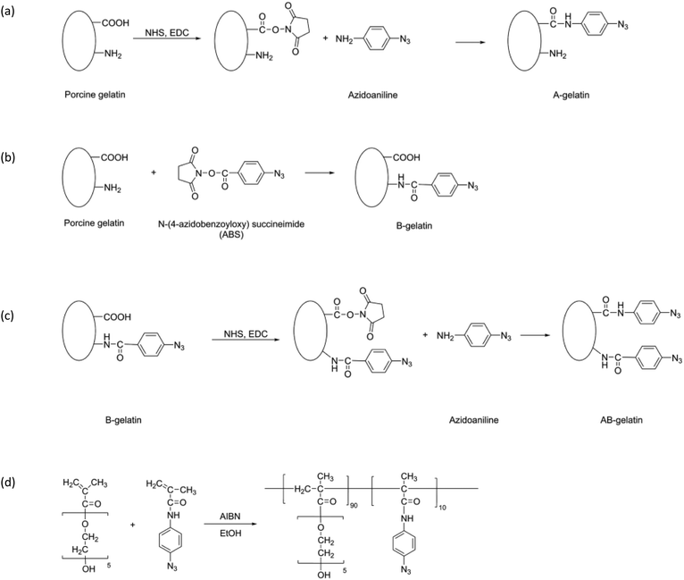 | ||
| Fig. 1 Synthetic scheme and chemical structures of photo-reactive polymers: (a) A-, (b) B-, and (c) AB-gelatin and (d) Az-PEG. | ||
Synthesis of A-gelatin
Porcine gelatin (200 mg) (G1890; Sigma-Aldrich, St. Louis, MO, USA) was completely dissolved in distilled water at 37 °C. To this gelatin solution, 2-(N-morpholino) ethanesulphonic acid (MES) solution (pH 4.5, 100 mL) was added to a final concentration of 50 mM. 4-Azidoaniline hydrochloride (40 mg), 1-ethyl-3-[3-dimethylaminopropyl] carbodiimide hydrochloride (EDC) (40 mg), and N-hydroxysuccinimide (NHS) (12 mg) were added to the MES-buffered gelatin solution, and the mixture was incubated at 30 °C for 4 h. The product was dialysed against distilled water and lyophilised.Synthesis of B-gelatin
The porcine gelatin (100 mg) dissolved in distilled water (100 mL) was added dropwise to an N-4-azido-benzoyloxysuccinimide (ABS) solution (100 mg, 0.380 mmol) in dimethylformamide (DMF) (100 mL). The solution was continuously stirred in an ice bath. After reaction at 4 °C for 24 h, the product was dialysed against distilled water and lyophilised.Synthesis of AB-gelatin
B-gelatin (50 mg) was dissolved in 50 mM MES buffer (pH 4.5, 100 mL), and subsequently 4-azidoaniline hydrochloride (10 mg), EDC (10 mg), and NHS (3 mg) were added to it. The mixture was incubated at 30 °C for 4 h and the product was dialysed against distilled water and lyophilised.Synthesis of Az-PEG
4-Azidophenylmethacrylamide was synthesized as previously reported34,36 and was co-polymerised with poly(ethylene glycol) methacrylate (PEG-MA) (680 mg) (#409537; Sigma-Aldrich, St Louis, MO, USA). It was mixed with N-(4-azidophenyl)-methacrylamide (33.2 mg) and azobisisobutyronitrile (5.6 mg) in 10 mL ethanol and polymerised for 18 h at 60 °C. The product, thus obtained, was evaporated to remove ethanol and purified by precipitation with ether. The product was characterised using gel permeation chromatography. The copolymer was dissolved in a mixture (1![[thin space (1/6-em)]](https://www.rsc.org/images/entities/char_2009.gif) :
:![[thin space (1/6-em)]](https://www.rsc.org/images/entities/char_2009.gif) 1) of ethanol and distilled water.
1) of ethanol and distilled water.
UV spectroscopy and measurement of the zeta potential
UV spectroscopy was performed for each photo-reactive polymer using an ultraviolet-visible (UV-Vis) spectrophotometer (V-550, JASCO Corporation, Tokyo, Japan). The zeta potential was measured using an ELSZ-2PL zeta potential and particle size analyser (Otsuka Electronics, Osaka, Japan). Two methods were applied to measure the zeta potential of the soluble polymers and the fabricated surface. The measurement of soluble polymers is based on the principle of electrophoretic mobility in an electric field. The samples were dissolved in double-distilled water with 5 mM NaCl and equilibrated at 37 °C. The measurement of the surface zeta potential is based on flow potential technology which has been widely applied to planar surfaces.37,38 Plate samples were set up in the flow cell, and the flow of dispersed particles (standard monitor particles: polystyrene latex coated with hydroxypropyl cellulose (∼500 nm Dia.)) was monitored in a 10 mM NaCl solution at pH 7. The Smoluchowski approximation was applied to both conversion equations for calculating the zeta potential.Florescence labelling of EGF
Human recombinant EGF (#236-EG; R&D Systems, Inc., Minneapolis, MN, USA) was conjugated with fluorescein isothiocyanate (FITC) (#F7250; Sigma-Aldrich, St Louis, MO, USA) for the evaluation of the immobilised protein. For FITC conjugation, 0.3 mg of EGF was dissolved in 100 μL of 0.1 M carbonate–bicarbonate buffer and was mixed with FITC (1.9 mg) in 30 μL of dimethylsulphoxide. The mixture was kept for 4 h in a dark place at 25 °C. The unreacted dye and buffer salts were removed using desalting columns (PD Spintrap™ G-25#28-9180-04; GE Healthcare, Buckinghamshire, UK). The fluorescein/protein molar ratio of FITC-EGF was evaluated to be 4.5 based on their absorbance at 280 and 495 nm. The protein concentration was determined using the equation described in the product information for FITC on the official website of SIGMA.Spin coating and immobilisation
The photo-reactive polymers, with or without EGF, were spin-coated on circular plastic plates (15 mm diameter Thermanox™ Coverslips, ThermoFisher Scientific, Cleveland, OH, USA). The plates were treated with plasma for 90 s and different concentrations of EGF with 0.1 wt% photo-reactive polymers were applied to the plasma-treated plates. The spin coating was performed as follows (Fig. S2, ESI†): (i) disperse stage: 1000 rpm, 5 s, (ii) substrate acceleration stage: 6 s, (iii) stable fluid outflow: 2000 rpm, 8 s, (iv) additional spinning: 5000 rpm, 3s. After drying, the plates were UV irradiated using an L5662 UV spotlight source (Hamamatsu photonics, Hamamatsu, Japan) with 10 mW cm−2 for 20 s to cross-link the photo-reactive polymers. The immobilised EGF-FITC was measured after removal of unbound EGF-FITC (Fig. S3, ESI†), and the calibration between fluorescence intensity and EGF-FITC amount was constructed using the standard curve (Fig. S4, ESI†). The removal of non-immobilised EGF was confirmed after ensuring that FITC-EGF was not detected in the washing solutions. The fluorescence was measured using an EnSpire™ Multimode Plate Reader (PerkinElmer, Waltham, MA, USA). The amount of immobilised EGF was estimated by calibrating known amounts of FITC-EGF immobilised on the surface. For FITC fluorescence, the excitation wavelength was 495 nm and the emission wavelength was 518 nm.Measurement of the thickness of polymers
The thickness of the polymers was measured using a spectroscopic ellipsometer (M-2000UI, J. A. Woollam, Co., NE, USA). First, the thickness and refractive index of relatively thick (>50 nm) samples were measured and thereafter the obtained refractive index was used in the analysis of thinner samples.Measurement of the contact angle
The water contact angles of plates were measured by dropping 2 μL of double distilled water on several spots at room temperature in air using a DropMaster contact angle meter (Kyowa Interface Science, Saitama, Japan).Immuno-staining
Immobilised EGF was stained as follows: 0.5 mg mL−1 of EGF was coated with 0.1 wt% photo-reactive polymer on the plate and immobilised through a photomask. The plate was incubated with a blocking solution (Block Ace; AbD Serotec, Oxford, UK) in Tris-buffered saline (Takara Bio USA Inc., Mountain View, CA, USA) containing 0.1% Tween-20 (TBS-T, Promega, Madison, WI, USA) for 4 h and was incubated overnight with 10 μg mL−1 anti-hEGF monoclonal antibody (#MAB236; clone 10825, R&D Systems, Minneapolis, MN, USA). Unbound antibody was removed by washing with TBS-T three times for 5 min each time. The treated plate was then incubated with the Alexa Fluor 488-conjugated goat anti-mouse antibody for 1 h at room temperature. After washing again with TBS-T three times, the stained surfaces were observed using a fluorescence microscope.Cell culture
A fibroblastic clone, derived from a normal rat kidney (NRK-49F), was procured from the Japanese Collection of Research Bioresources Cell Bank. The cells were cultured in Dulbecco's modified Eagle's medium (DMEM; FUJIFILM Wako Pure Chemical Industries, Ltd, Osaka, Japan), supplemented with 10% foetal bovine serum (FBS, Chile Origin, USDA approved; FB-1365/500, Biosera, Nuaille, France), and 1% penicillin–streptomycin (Nacalai Tesque, Inc., Kyoto, Japan) at 37 °C with 5% CO2. The cells were harvested after treating with 0.25% trypsin, containing 1 mM ethylenediaminetetraacetic acid (Gibco, Thermo Fisher Scientific, Rockford, IL, USA), for 3 min at 37 °C and suspended in culture medium or low serum containing DMEM with 0.5% FBS for in vitro examination.Evaluation of attachment and growth of cells
Cell attachment was evaluated by staining F-actin as previously reported.39–41 A suspension of cells in 500 μL DMEM, supplemented with 10% FBS, was added to the wells of each 24-well plate at a density 5 × 10³ well−1. The plate was centrifuged at 1000 rpm for 3 min to initiate cell adhesion and then incubated at 37 °C for 1 h. After the incubation, the medium was gently pipetted to re-suspend the unattached cells and the medium was replaced with fresh PBS. PBS was then replaced with 4% paraformaldehyde and the plates were incubated for 15 min at room temperature to allow the fixing of cells. The fixative was aspirated and the samples were washed three times with PBS for 5 min each time. PBS was replaced with 0.1% Triton X-100 in PBS and the plates were incubated for 15 min at room temperature. After washing with PBS, the samples were stained with phalloidin 568 for 60 min and with Hoechst33342 (1![[thin space (1/6-em)]](https://www.rsc.org/images/entities/char_2009.gif) :
:![[thin space (1/6-em)]](https://www.rsc.org/images/entities/char_2009.gif) 5000) for 30 min. The plates were again washed with PBS, and the cells were observed using a fluorescence microscope. The area showing cell attachment was analysed using the ImageJ and Prism software.
5000) for 30 min. The plates were again washed with PBS, and the cells were observed using a fluorescence microscope. The area showing cell attachment was analysed using the ImageJ and Prism software.
The cell growth was estimated from the cell number using a Cell Counting Kit-8 (CCK-8; Dojindo, Kumamoto, Japan). CCK-8 solution was added to the cell culture medium at a ratio of 1![[thin space (1/6-em)]](https://www.rsc.org/images/entities/char_2009.gif) :
:![[thin space (1/6-em)]](https://www.rsc.org/images/entities/char_2009.gif) 10 and incubated at 37 °C for 1 h under a humidified atmosphere containing 5% CO2. The reactants were transferred to a 96-well plate and the absorbance was measured at 450 nm using an EnSpire™ Multimode Plate Reader.
10 and incubated at 37 °C for 1 h under a humidified atmosphere containing 5% CO2. The reactants were transferred to a 96-well plate and the absorbance was measured at 450 nm using an EnSpire™ Multimode Plate Reader.
Results and discussion
Characterisation of photo-reactive polymers
The presence of conjugated azidophenyl groups in the prepared polymers was confirmed using UV absorbance spectra (Fig. S1, ESI†). The quantification of azidophenyl groups in each polymer was performed by measuring the absorbance at 265 nm applying the Beer–Lambert law and using a molecular coefficient of 18![[thin space (1/6-em)]](https://www.rsc.org/images/entities/char_2009.gif) 000 M−1 cm−1, reported previously.42 The same coefficient constant was assumed for determining the content of the azidophenyl group (Table 1). Type A gelatin has 86 cationic amino acids, including lysine, hyroxylysine, histidine, and arginine, and 118 anionic amino acids, such as glutamic acid and aspartic acid, per 1000 amino acids.43,44 In A-gelatin, 3.9 carboxyl groups are reduced by coupling with the azidophenyl group. In B-gelatin, 2.7 amino groups are reduced by coupling with the azidophenyl group. Both carboxyl and amino groups are sequentially reduced in AB-gelatin and result in 5.7 azidophenyl groups in each gelatin polymer. Az-PEG is formed by copolymerisation of the two types of monomer, and the content of the azidophenyl group in this polymer is higher than in photo-reactive gelatins synthesised in the present study. The azidophenyl content of Az-PEG was estimated to be 8.6 with feeding in the copolymer of N-(4-azidophenyl)-methacrylamide and (poly(ethylene glycol)) methacrylate.
000 M−1 cm−1, reported previously.42 The same coefficient constant was assumed for determining the content of the azidophenyl group (Table 1). Type A gelatin has 86 cationic amino acids, including lysine, hyroxylysine, histidine, and arginine, and 118 anionic amino acids, such as glutamic acid and aspartic acid, per 1000 amino acids.43,44 In A-gelatin, 3.9 carboxyl groups are reduced by coupling with the azidophenyl group. In B-gelatin, 2.7 amino groups are reduced by coupling with the azidophenyl group. Both carboxyl and amino groups are sequentially reduced in AB-gelatin and result in 5.7 azidophenyl groups in each gelatin polymer. Az-PEG is formed by copolymerisation of the two types of monomer, and the content of the azidophenyl group in this polymer is higher than in photo-reactive gelatins synthesised in the present study. The azidophenyl content of Az-PEG was estimated to be 8.6 with feeding in the copolymer of N-(4-azidophenyl)-methacrylamide and (poly(ethylene glycol)) methacrylate.
| Sample | Azidophenyl group/polymer | Zeta-potential (mV) |
|---|---|---|
| Gelatin | 0 | 3.8 ± 0.6 |
| A-gelatin | 3.9 | 10.4 ± 0.7 |
| B-gelatin | 2.7 | 1.8 ± 0.2 |
| AB-gelatin | 5.7 | 4.3 ± 0.2 |
| Az-PEG | 8.6 | 1.6 ± 1.6 |
The zeta potential is shown in Table 1. The zeta potential of unmodified type A gelatin was measured at pH 7, which was below the isoelectronic point of unmodified type A porcine gelatin (pH 9) and, therefore, had a positive zeta potential value, close to 0.42 The zeta potentials of other gelatins synthesised in the present study were also measured at pH 7. A-gelatin had a higher zeta potential of 10.4 ± 0.7 mV, which corresponded with the reduced carboxyl groups. B-gelatin had a lower zeta potential of 1.8 ± 0.2 mV because none of the carboxyl groups were reduced. AB-gelatin had a zeta potential of 4.3 ± 0.2 mV, which is intermediate between those of A- and B-gelatin, and close to that of original porcine gelatin before chemical modification. Because Az-PEG is non-ionic, its zeta potential was 1.6 ± 1.6 mV, which was close to that of the non-electrical state.
Surface treatment by photo-reactive polymers
The plasma treatment was performed to prepare a hydrophilic surface before spin coating as the hydrophobic surface of Thermanox™ Coverslip was not suitable for spreading of the aqueous solution of polymers. All polymer-coated surfaces had a similar contact angle, indicating the same level of hydrophilicity (Fig. 2).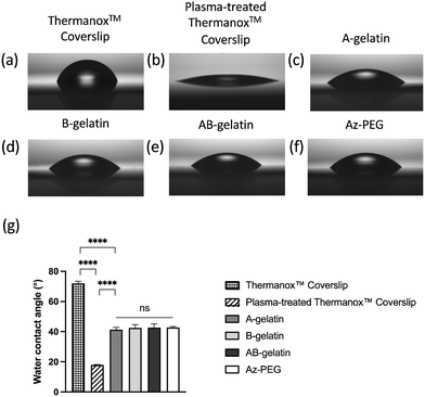 | ||
| Fig. 2 Water contact angles of treated ThermanoxTM Coverslips. For coating, 0.1 wt% polymers were used. The measurement of contact angles applying different treatments and coatings are shown as Fig. 2(a)–(f) and the statistical analysis is shown in Fig. 2(g). The values shown are mean ± SD (n = 5, **** p < 0.0001, analysed using the t-test). | ||
The thickness of the coated polymers was measured using ellipsometry after applying different concentrations of polymers (Table 2). The reduction in the polymer concentration led to a decrease in thickness. The relationship between the feed content and thickness was almost the same as that of the polymers used in this study. These results demonstrate that the physico-chemical properties of the prepared polymers were not different.
| Feed conc. (wt%) | Thickness (nm) | |||
|---|---|---|---|---|
| A-gelatin | B-gelatin | AB-gelatin | Az-PEG | |
| 1 | 50 | 65 | 52 | 68 |
| 0.1 | 5.3 | 6.5 | 5.8 | 6.4 |
| 0.01 | 0.43 | 0.51 | 0.54 | 1.2 |
Considering the relationship between the feed and coated amount of polymers calculated from the thickness, 12–15% of the feeding polymers were on the plate. Under a typical spin coating process (5000 rpm), 2–5% of the material was reported to be dispensed on the substrate.45 We believe that under the conditions employed by us for spin coating, less time may have caused the high amount of coated material.
The surface zeta potentials are shown in Fig. 4, which were measured as −47.2 ± 1.2mV for the non-immobilised plate. The immobilisation of photo-reactive polymers reduced the negative value of the surface. This reduction depended on the nature of the polymer.
The Thermanox plate surface had a negative zeta potential, which was similar to those of conventional polymers such as polystyrene, polypropylene, polyethylene, or polyamide, having a range from –25 mV to –75mV at pH 7.38,46 The immobilised photo-reactive gelatins reduced the negative value of zeta potential because these polymers had positive zeta potentials, as shown in Table 1. The effects depend on the nature of the photoreactive polymers. A-gelatin reduced the negative value more than B-gelatin or AB-gelatin did. Az-PEG showed a lower effect on zeta potentials than the photo-reactive gelatins.
Immobilisation of EGF
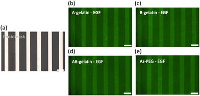
To verify the immobilisation of EGF by each polymer, photo-masking (Fig. 3(a)) was employed, and the pattern was confirmed using immuno-staining with the anti-hEGF antibody (Fig. 3(b)–(e)). The mechanism underlying the immobilisation of protein using the azidophenyl group is illustrated in Fig. S5(a) (ESI†).48,49 The UV irradiation triggered photo-activation to produce singlet nitrene or cause ring expansion of the azidophenyl group into dehydroazepine, which initiated covalent bond formation to cross-link with proteins, substrate, and other polymers, as shown in Fig. S5(b) (ESI†).Table 3 shows the relationship between the amount of immobilised EGF and photo-reactive polymer matrices calculated based on the thickness. The amount of immobilised EGF increased with the increase in the amount of EGF feed. Because the content of azidophenyl groups in AB-gelatin is more than in A- and B-gelatins, it provided a higher amount of immobilised EGF on the surface.
| Feeding polymer (μg μL−1) | Feeding EGF (ng μL−1) | EGF on substrate (ng cm−2) | Immobilisation efficiency (%) | Feed azidophenyl group per EGF | Immobilised azidophenyl group per EGF | |
|---|---|---|---|---|---|---|
| A-gelatin | 1 | 6.25 | 3.9 ± 0.4 | 11.0 ± 1.2 | 374.4 | 414.5 |
| 1 | 25 | 5.5 ± 0.5 | 3.9 ± 0.3 | 93.6 | 297.9 | |
| 1 | 100 | 10.6 ± 1.0 | 1.9 ± 0.2 | 23.4 | 152.9 | |
| 1 | 62.5 | 3.0 ± 0.5 | 8.4 ± 1.5 | 259.2 | 462.1 | |
| B-gelatin | 1 | 25 | 6.3 ± 1.2 | 4.4 ± 0.8 | 64.8 | 216.5 |
| 1 | 100 | 13.1 ± 1.5 | 2.3 ± 0.3 | 16.2 | 104.0 | |
| 1 | 6.25 | 3.4 ± 0.6 | 9.7 ± 1.8 | 547.2 | 742.8 | |
| AB-gelatin | 1 | 25 | 7.5 ± 1.9 | 5.3 ± 1.3 | 136.8 | 343.3 |
| 1 | 100 | 16.5 ± 0.9 | 2.9 ± 0.2 | 34.2 | 155.2 | |
| 1 | 6.25 | 3.6 ± 4.0 | 10.3 ± 11.4 | 461.0 | 563.0 | |
| Az-PEG | 1 | 25 | 13.9 ± 7.9 | 9.8 ± 5.6 | 115.2 | 147.1 |
| 1 | 100 | 45.6 ± 6.1 | 8.1 ± 1.1 | 28.8 | 44.7 |
Among the four photo-reactive polymers, Az-PEG had 8.6 azidophenyl groups per polymer molecule (Table 1) and had the highest immobilised amount of EGF among the four polymers. Therefore, Az-PEG showed the highest amount of immobilised EGF on the substrate compared with the other photo-reactive gelatins.
In contrast, the immobilisation efficiency decreased with the increase in the feeding ratio of EGF. Although the amount of azidophenyl groups was in excess of the amount of EGF, the ratio decreased from 414.5–742.8 to 44.7–155.2. In the feed, the ratio decreased from 259.2–547.2 to 16.2–34.2 (Table 3). Besides, azidophenyl groups were not only consumed in the immobilisation of EGF, but some were consumed in the formation of covalent bonds with the substrate and cross-linked polymers as well (Fig. S5(b), ESI†).
The calculated density of the immobilised EGF ranged from 3.10 × 10³ to 4.77 × 10⁴ molecules μm−2 (Table 3). In contrast, assuming the effective radius of EGF molecules to be 0.8 nm (as given on https://3vee.molmovdb.org/) and that they were arranged in a hexagonal close-packed manner, the full coverage of EGF on a slide with 15 mm diameter being estimated to be 4.1 × 10⁵ molecules μm−2. These calculations suggest that EGF occupied 0.7–12% of the fully occupied monolayer on the surface. The thickness of the immobilised surface ranged from 5.3 to 6.5 nm (Table 2) and based on the effective radius of EGF, the limited and effective exposure of EGF was inferred.
The density of the EGF receptor (EGFR) on the cell surface has been estimated by some researchers. Zhang et al. analysed the density on of A431, HeLa, and A549 cell lines using surface plasma resonance imaging and showed it to range from 142 to 636 molecules μm−2.50 Harms et al. investigated the expression of EGFR in U87MG, H1975, and A431 cell lines, and found the EGFR densities to be 5.8 × 10⁴, 3.6 × 10⁵, and 2.0 × 10⁶ receptors per cell, respectively, using quantitative flow cytometry.51 Zheng et al. reported EGFR densities to range from 6.32 × 10⁴ to 8.23 × 10⁵ receptors/cell by analysing eight cell lines.52 Assuming the cell surface area to be 1.26 × 103 μm2 (diameter: 20 μm), the EGFR density is estimated to range from 50 to 1600 molecules μm−2. Although photo-immobilisation cannot regulate the orientation of EGF, the density of surface immobilised EGF in the present study was considered to exceed the range of EGF receptor density on cells during interaction of the cell and the EGF immobilised surface.
Immobilisation with EGF did not significantly affect the zeta potential in the case of photo-reactive gelatins (Fig. 4(a)–(c)), although recombinant human EGF has a negative zeta potential in the range of −7 to −30 mV according to the nature of the buffer.47 This was due to the low EGF content in the immobilised layers (5.7–9.3%). However, because the highest content of EGF in Az-PEG was 31.4%, EGF had different effects on the surface zeta potential.
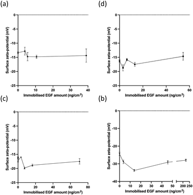 | ||
| Fig. 4 The surface charges of immobilised EGF with different photo-reactive polymers. The surface zeta potential of EGF immobilised using (a) A-gelatin, (b) B-gelatin, (c) AB-gelatin, and (d) Az-PEG. | ||
Cell attachment
The stained cell images for the cell attachment evaluation are demonstrated in Fig. S6 (ESI†) and the attachment of cells to different photo-reactive polymers is summarized in Fig. 5. A-gelatin promoted the attachment of cells, whereas B-gelatin did not. Considering the known fact that cationic surfaces, such as that of amino groups, promote cell adhesion,53 the same effect was observed in the present study. The much higher cell spreading effect observed in AB-gelatin was assumed to be due to stronger cross-linking by higher azidophenyl group in AB-gelatin. Higher degree of cross-linking is considered to be associated with a higher stiffness, which determines the cellular morphology and facilitates cell spreading.54–57 In contrast, PEG reduces protein adsorption58 and was reported to control cell shape and projected areas59 and surface immobilisation with Az-PEG showed reduced adhesion of cells,60 which is employed in the design of materials and was used in the present study.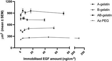 | ||
| Fig. 5 Cell adhesion on different polymer-coated surfaces, with or without EGF. The values shown are mean ± SEM. | ||
Although the properties of matrix polymers affected the attachment of cells, the increment in the amount of immobilised EGF did not significantly influence the attachment of cells (Fig. 5). Immobilised EGF was not considered to directly induce the reconstruction of the cytoskeleton.
Cell growth
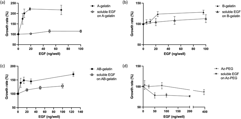
The cell growth in the presence of soluble EGF was compared (Fig. 6). On surfaces fabricated with different polymers, immobilised EGF generally enhanced the cell growth more than that observed for soluble EGF. Compared with soluble EGF, immobilised EGF enhanced the cell growth through multivalent stimulation, high local concentrations in the area of interaction between cell and substrate, and by inhibiting the down-regulation of EGF receptors in cells.15,26,31 The matrix polymers significantly affected the growth enhancement. In the presence of soluble EGF, AB-gelatin was the most effective, followed by B-gelatin. A-gelatin was not as effective for the growth of cells as was soluble EGF. EGF immobilised using Az-PEG significantly reduced the cell growth. Az-PEG reduced not only cell attachment but also interaction between immobilised EGF and EGFR on cells, and therefore, no cell growth enhancement was observed. Additionally, loss of cell attachment is considered to cause programmed cell death, which counteracts enhancement in the cell growth by EGF.61,62The characteristics of the immobilising matrix affected the cell growth with the immobilised EGF more significantly. Higher promotion of cell growth rate by EGF was observed on the A-gelatin surface. The enhancement in cell growth of B- and AB-gelatin was significantly less than that of A-gelatin. We believe that the cationic surface of A-gelatin promotes the interaction of immobilised EGF and EGFR. A-gelatin was designed to expose more amino groups, because of which better cell attachment and cell growth were observed. B-gelatin exposes more carboxyl groups, because of which lower cell attachment and cell growth were observed. Cell culture on a surface with amino groups was reported to exhibit higher cell growth and adhesion than that on a surface with carboxyl groups.63
The relationship between the growth and attachment of cells on the immobilised and soluble EGF with different photo-reactive polymers is summarized in Fig. 7. It is seen that the matrix polymers significantly affected the cell behaviour with immobilised EGF more than with soluble EGF. Tang et al.27 reported that the stiffness of an artificial matrix for immobilisation of transforming growth factor-beta 1 affected the signalling with coupling of mechano-transduction. The present study also demonstrates the importance of matrices for immobilizing growth factors. Higher cell attachment ensures cell survival in the early stages of cell seeding by avoiding anoikis.64 Lower cell attachment did not enhance the cell growth under any condition. However, the highest cell attachment was observed on the AB-gelatin immobilised surface, but the cell growth rate did not increase with the cell attachment. Cell morphology changes during cell cycle and the coordination of actin, integrin, and focal adhesion ensures proper mitosis.65–67 During cytokinesis, both proper adhesion and contractility are required to complete cell division. Polar traction forces coordinate with the cell rounding process due to lower focal adhesion and high cortical tension.68 Therefore, a material designed for maximizing cell attachment does not ensure the highest cell growth rate; rather, moderate cell attachment is preferable for cell growth.
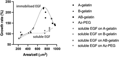 | ||
| Fig. 7 Integration of cell growth rate (%) and cell attached area (μm2) on different photo-reactive gelatins and Az-PEG using the data presented in Fig. 5 and 6. | ||
Conclusions
EGF was photo-immobilised with photo-reactive gelatins and polyethylene oxide. The physico-chemical properties such as contact angle, zeta-potential, and thickness were investigated and the amount of immobilised EGF was quantitatively determined by fluorescent labelling. Not only the immobilsed EGF, but also the immobilised polymers significantly affected the cell attachment and growth. The results of this study show that the matrix properties must be taken into consideration in the immobilisation of GFs, although the immobilisation enhances the effects of GFs.Author contributions
Yoshihiro Ito conceived the whole project and designed the materials, and Liang-Chun Wu conceived and performed material characterization and experiments of bioactivity. Takeshi Serizawa and Seiichi Tada contributed the instructions and discussion. Takashi Isoshima contributed thickness measurements. Liang-Chun Wu and Yoshihiro Ito wrote the manuscript.Conflicts of interest
There are no conflicts of interest to declare.Acknowledgements
Liang-Chun Wu thanks Dr Masashi Ueki for his technical support, Drs Akimoto, Ueda, and Uzawa for the discussion, and Ms Obuse for her preparation of Az-PEG.Notes and references
- D. Nieto, J. A. Marchal Corrales, A. Jorge de Mora and L. Moroni, APL Bioeng., 2020, 4, 041502 CrossRef CAS PubMed.
- Q. Zhang, H.-P. Bei, M. Zhao, Z. Dong and X. Zhao, Biomaterials, 2022, 286, 121566 CrossRef CAS PubMed.
- L. Tytgat, A. Dobos, M. Markovic, L. Van Damme, J. Van Hoorick, F. Bray, H. Thienpont, H. Ottevaere, P. Dubruel, A. Ovsianikov and S. Van Vlierberghe, Biomacromolecules, 2020, 21, 3997–4007 CrossRef CAS PubMed.
- A. GhavamiNejad, N. Ashammakhi, X. Y. Wu and A. Khademhosseini, Small, 2020, 16, 2002931 CrossRef CAS PubMed.
- R. F. Pereira and P. J. Bártolo, J. Appl. Polym. Sci., 2015, 132, 42458 CrossRef.
- S. Anil Kumar, M. Alonzo, S. C. Allen, L. Abelseth, V. Thakur, J. Akimoto, Y. Ito, S. M. Willerth, L. Suggs, M. Chattopadhyay and B. Joddar, ACS Biomater. Sci. Eng., 2019, 5, 4551–4563 CrossRef CAS PubMed.
- L. Pierau and D.-L. Versace, Materials, 2021, 14, 787 CrossRef CAS PubMed.
- L. Pierau, C. Elian, J. Akimoto, Y. Ito, S. Caillol and D.-L. Versace, Prog. Polym. Sci., 2022, 127, 101517 CrossRef CAS.
- D.-L. Versace, J. Ramier, D. Grande, S. A. Andaloussi, P. Dubot, N. Hobeika, J.-P. Malval, J. Lalevee, E. Renard and V. Langlois, Adv. Healthcare Mater., 2013, 2, 1008–1018 CrossRef CAS PubMed.
- L. Li, J. M. Scheiger and P. A. Levkin, Adv. Mater., 2019, 31, 1807333 CrossRef PubMed.
- S. Shanmugam, J. Xu and C. Boyer, J. Am. Chem. Soc., 2015, 137, 9174–9185 CrossRef CAS PubMed.
- J. Xu, K. Jung, A. Atme, S. Shanmugam and C. Boyer, J. Am. Chem. Soc., 2014, 136, 5508–5519 CrossRef CAS PubMed.
- A. J. Gormley, J. Yeow, G. Ng, Ó. Conway, C. Boyer and R. Chapman, Angew. Chem., Int. Ed., 2018, 57, 1557–1562 CrossRef CAS PubMed.
- N. Corrigan, F. J. Trujillo, J. Xu, G. Moad, C. J. Hawker and C. Boyer, Macromolecules, 2021, 54, 3430–3446 CrossRef CAS.
- Y. Ito, J. Zheng, Y. Imanishi, K. Yonezawa and M. Kasuga, Proc. Natl. Acad. Sci. U. S. A., 1996, 93, 3598–3601 CrossRef CAS PubMed.
- Y. Ito, S. Qin Liu and Y. Imanishi, Biomaterials, 1991, 12, 449–453 CrossRef CAS PubMed.
- Y. Ito, ACS Biomater. Sci. Eng., 2019, 5, 5597–5609 CrossRef CAS PubMed.
- Y. Ito, J. S. Li, T. Takahashi, Y. Imanishi, Y. Okabayashi, Y. Kido and M. Kasuga, J. Biochem., 1997, 121, 514–520 CrossRef CAS PubMed.
- Y. Hirano and D. J. Mooney, Adv. Mater., 2004, 16, 17–25 CrossRef CAS.
- D. Enriquez-Ochoa, P. Robles-Ovalle, K. Mayolo-Deloisa and M. E. G. Brunck, Front. Bioeng. Biotechnol., 2020, 8, 620 CrossRef PubMed.
- P. P. Girard, E. A. Cavalcanti-Adam, R. Kemkemer and J. P. Spatz, Soft Matter, 2007, 3, 307–326 RSC.
- P. Anklesaria, J. Teixidó, M. Laiho, J. H. Pierce, J. S. Greenberger and J. Massagué, Proc. Natl. Acad. Sci. U. S. A., 1990, 87, 3289–3293 CrossRef CAS PubMed.
- P. R. Kuhl and L. G. Griffith-Cima, Nat. Med., 1996, 2, 1022–1027 CrossRef CAS PubMed.
- Y. Ito, Biomaterials, 1999, 20, 2333–2342 CrossRef CAS PubMed.
- Y. Ito, Soft Matter, 2008, 4, 46–56 RSC.
- S. Tada, X. Ren, H. Mao, Y. Heo, S.-H. Park, T. Isoshima, L. Zhu, X. Zhou, R. Ito, S. Kurata, M. Osaki, E. Kobatake and Y. Ito, Adv. Sci., 2021, 8, 2100961 CrossRef CAS PubMed.
- R.-Z. Tang, S.-S. Gu, X.-T. Chen, L.-J. He, K.-P. Wang and X.-Q. Liu, ACS Appl. Mater. Interfaces, 2019, 11, 14660–14671 CrossRef CAS PubMed.
- H. Makino, H. Hasuda and Y. Ito, J. Biosci. Bioeng., 2004, 98, 374–379 CrossRef CAS PubMed.
- Y. Ito, S. Kondo, G. Chen and Y. Imanishi, FEBS Lett., 1997, 403, 159–162 CrossRef CAS PubMed.
- Y. Ito, G. Chen, Y. Imanishi, T. Morooka, E. Nishida, Y. Okabayashi and M. Kasuga, J. Biochem., 2001, 129, 733–737 CrossRef CAS PubMed.
- G. Chen, Y. Ito and Y. Imanishi, Biochim. Biophys. Acta, Mol. Cell. Res., 1997, 1358, 200–208 CrossRef CAS PubMed.
- S.-H. Park, S.-Y. Seo, J.-H. Kang, Y. Ito and T.-I. Son, J. Appl. Polym. Sci., 2013, 127, 154–160 CrossRef CAS.
- S. Müller, M. Ueda, T. Isoshima, T. Ushida and Y. Ito, J. Mater. Chem. B, 2020, 8, 416–425 RSC.
- Y. Ito, H. Hasuda, M. Sakuragi and S. Tsuzuki, Acta Biomater., 2007, 3, 1024–1032 CrossRef CAS PubMed.
- Y. Weng, J. R. Ren, N. Huang, J. Wang, J. Chen, Y. Leng and H. Liu, Mater. Sci. Eng., C, 2008, 1495–1500 CrossRef CAS.
- H. Kashiwagi, N. Morishima, S. Obuse, T. Isoshima, J. Akimoto and Y. Ito, BCSJ, 2021, 94, 2435–2443 CrossRef CAS.
- S. Chen, H. Dong and J. Yang, Sensors, 2020, 20, 1690 CrossRef CAS PubMed.
- A. Voigt, H. Wolf, S. Lauekner, G. Neumann, R. Becker and L. Richter, Biomaterials, 1983, 4, 299–304 CrossRef CAS PubMed.
- A. I. Bachir, A. R. Horwitz, W. J. Nelson and J. M. Bianchini, Cold Spring Harb. Perspect. Biol., 2017, 9, a023234 CrossRef PubMed.
- U. S. Schwarz and M. L. Gardel, J. Cell Sci., 2012, 125, 3051–3060 CAS.
- T. D. Pollard and J. A. Cooper, Science, 2009, 326, 1208–1212 CrossRef CAS PubMed.
- M. W. Geiger, M. M. Elliot, V. D. Karacostas, T. J. Moricone, J. B. Salmon, V. L. Sideli and M. A. St. Onge, Photochem. Photobiol., 1984, 40, 545–548 CrossRef CAS.
- A. A. Karim and R. Bhat, Food Hydrocoll., 2009, 23, 563–576 CrossRef CAS.
- S. R. Derkach, N. G. Voron’ko, Y. A. Kuchina and D. S. Kolotova, Polymers, 2020, 12, 3051 CrossRef CAS PubMed.
- N. Sahu, B. Parija and S. Panigrahi, Indian J. Phys., 2009, 83, 493–502 CrossRef CAS.
- G. Petzold, S. Schwarz and V. Dutschk, Colloid Polym. Sci., 2014, 292, 2197–2205 CrossRef CAS.
- N. A. Kim, D. G. Lim, J. Y. Lim, K. H. Kim and S. H. Jeong, Drug Dev. Ind. Pharm., 2015, 41, 300–306 CrossRef CAS PubMed.
- A. Isor, R. Hommelsheim, G. W. Cone, M. Frings, J. T. Petroff II, C. Bolm and R. D. McCulla, Photochem. Photobiol., 2021, 97, 1322–1334 CrossRef CAS PubMed.
- M. S. Platz, Acc. Chem. Res., 1995, 28, 487–492 CrossRef CAS.
- F. Zhang, S. Wang, L. Yin, Y. Yang, Y. Guan, W. Wang, H. Xu and N. Tao, Anal. Chem., 2015, 87, 9960–9965 CrossRef CAS PubMed.
- B. D. Harms, J. D. Kearns, S. V. Su, N. Kohli, U. B. Nielsen and B. Schoeberl, Meth. Enzymol., 2012, 502, 67–87 CrossRef CAS PubMed.
- S. Zheng, S. Moores, S. Jarantow, J. Pardinas, M. Chiu, H. Zhou and W. Wang, MAbs, 2016, 8, 551–561 CrossRef CAS PubMed.
- J. M. Curran, R. Stokes, E. Irvine, D. Graham, N. A. Amro, R. G. Sanedrin, H. Jamil and J. A. Hunt, Lab Chip, 2010, 10, 1662–1670 RSC.
- M. Y. M. Chiang, Y. Yangben, N. J. Lin, J. L. Zhong and L. Yang, Biomaterials, 2013, 34, 9754–9762 CrossRef CAS PubMed.
- R. G. Wells, Hepatology, 2008, 47, 1394–1400 CrossRef CAS PubMed.
- T. Yeung, P. C. Georges, L. A. Flanagan, B. Marg, M. Ortiz, M. Funaki, N. Zahir, W. Ming, V. Weaver and P. A. Janmey, Cell Motil. Cytoskeleton, 2005, 60, 24–34 CrossRef PubMed.
- S. Lin and L. Gu, Materials, 2015, 8, 551 CrossRef PubMed.
- W. R. Gombotz, G. H. Wang, T. A. Horbett and A. S. Hoffman, J. Biomed. Mater. Res., 1991, 25, 1547–1562 CrossRef CAS PubMed.
- C. H. Thomas, J.-B. Lhoest, D. G. Castner, C. D. McFarland and K. E. Healy, J. Biomech. Eng., 1999, 121, 40–48 CrossRef CAS PubMed.
- J. Akimoto, S. J. Park, S. Obuse, M. Kawamoto, M. Tamura, A. Nandakumar, E. Kobatake and Y. Ito, ACS Appl. Bio Mater., 2020, 3, 5941–5947 CrossRef CAS PubMed.
- S. M. Frisch and E. Ruoslahti, Curr. Opin. Cell Biol., 1997, 9, 701–706 CrossRef CAS PubMed.
- B. Zhao, L. Li, L. Wang, C.-Y. Wang, J. Yu and K.-L. Guan, Genes Dev., 2012, 26, 54–68 CrossRef CAS PubMed.
- J. H. Lee, H. W. Jung, I. K. Kang and H. B. Lee, Biomaterials, 1994, 15, 705–711 CrossRef CAS PubMed.
- P. J. Reddig and R. L. Juliano, Cancer Metastasis Rev., 2005, 24, 425–439 CrossRef PubMed.
- E. N. Pugacheva, F. Roegiers and E. A. Golemis, Curr. Opin. Cell Biol., 2006, 18, 507–515 CrossRef CAS PubMed.
- M. C. Jones, J. Zha and M. J. Humphries, Philos. Trans. R. Soc. Lond., B, Biol. Sci., 2019, 374, 20180227 CrossRef CAS PubMed.
- G. Weder, J. Vörös, M. Giazzon, N. Matthey, H. Heinzelmann and M. Liley, Biointerphases, 2009, 4, 27–34 CrossRef PubMed.
- A. V. Taubenberger, B. Baum and H. K. Matthews, Front. Cell Dev. Biol., 2020, 8, 687 CrossRef PubMed.
Footnote |
| † Electronic supplementary information (ESI) available. See DOI: https://doi.org/10.1039/d2tb02040h |
| This journal is © The Royal Society of Chemistry 2023 |

