Preparation of acid-driven magnetically imprinted micromotors and selective loading of phycocyanin†
Guangdong
Yang‡
a,
Jiajing
Liu‡
c,
Zhong
Zhang
 *ab,
Li
Yuan
 a,
Hongye
Tian
 a and
Xingbin
Yang
 a
a
aShaanxi Engineering Laboratory for Food Green Processing and Safety Control, Engineering Research Center of High Value Utilization of Western Fruit Resources, Ministry of Education, College of Food Engineering and Nutritional Science, Shaanxi Normal University, Xi’an, Shaanxi 710119, P. R. China. E-mail: zzhang@snnu.edu.cn; Fax: +86 10-85310517; Tel: +86 10-85310517
bXi’an Key Laboratory of Characteristic Fruit Storage and Preservation, Shaanxi Key Laboratory for Hazard Factors Assessment in Processing and Storage of Agricultural Products, Shaanxi Normal University, Xi’an, Shaanxi 710119, P. R. China
cSchool of Food Science and Engineering, South China University of Technology, Guangzhou, Guangdong, 510641, P. R. China
First published on 31st October 2023
Abstract
Phycocyanin, a macromolecular protein known for its robust fluorescence, proves to be highly suitable for verifying the successful deposition of imprinted layers. In this study, an acid-propelled magnetic micromotor was successfully fabricated by utilizing surface imprinting and self-propelled nanomotor technology to achieve selective loading and capture of targets such as phycocyanin for future applications in environmental monitoring and precision drug delivery in vivo. This micromotor features a distinct recognition layer achieved through a template electrodeposition method. The outermost imprint layer of the micromotor was meticulously crafted using poly(3,4-ethylenedioxythiophene)/poly(sodium-4-styrenesulfonate) in the presence of a template, while the Pt layer serves as the supportive foundation, the Ni layer acts as the magnetic guidance component, and the innermost layer consists of metal Zn. In acidic environments, the Zn reacts to generate bubbles, which propels the micromotor's motion. The micromotor was comprehensively characterized using techniques such as scanning electron microscopy. Findings highlight the exceptional self-propulsion of the Zn-based micromotor, which is a fusion of molecular imprinting and micromotor technologies. This innovative design achieves an impressive maximum velocity of approximately 100 μm s−1, as well as commendable magnetic steering performance. Furthermore, the micromotor demonstrates the ability to imprint target protein through the imprint layer, enabling selective recognition and capture for transport of specific phycocyanin. In vitro cytotoxicity tests have also demonstrated that the micromotors are non-toxic to cells. This breakthrough concept offers a novel avenue for realizing targeted capture and transport of specific nutrients within the human gastric environment.
1. Introduction
In recent years, the rapid development of self-driven micro and nanomotor technology has achieved significant advancements in various applications, such as environmental remediation,1 drug delivery,2 water purification,3 DeoxyriboNucleic acid (DNA) recognition,4 and other fields. This trend represents a crucial direction within the current domain of nanoscience. Self-driven micro and nanomotors, as implied by their name, are characterized primarily by their small size, operating at the micro and nanoscale levels, and displaying spontaneous movement. These motors can convert different forms of energy, such as chemical, electric, and light energies, into kinetic energy.Categorized by their driving mechanisms, micromotors generally fall into five distinct categories: chemical-, magnetic-, optical-,5–7 ultrasonic-, and electric field-driven.8 Particularly, chemical-driven micromotors, which convert chemical energy into kinetic energy, are widely used and possess significant potential. Depending on the specific fuels utilized, they can be classified into hydrogen peroxide,9,10 water,11,12 hydrazine,13 and acid-driven14 types.
The exploration of micromotors originated from a captivating chemical experiment. Whitesides et al. (2002)15 successfully designed and developed a self-propelled device using hydrogen peroxide as fuel, catalyzed by Pt to produce bubbles. This experiment garnered considerable attention, prompting researchers to delve into the study of self-driven micro and nanoscale devices, marking the inception of micromotor research. The year 2004 witnessed the development of the first Au/Pt catalytic micromotor,16 ushering in a period of rapid nanomotor evolution. As micromotor technology progressed, various preparation methods emerged, including template-assisted electrodeposition,17 physical vapor deposition,12 crimping method,18 and Pickering emulsion method.9,19 Each method boasts unique features, enabling the synthesis of diverse micromotor shapes, such as tubes, rods, spirals, and spheres. Researchers continuously strive for excellence, setting high standards for motion performance and aspiring to attain precise and controllable micromotor manipulation. Techniques such as magnetic,20 ultrasonic,21 and electric fields22 have been developed to regulate micromotor movement.
Despite the rapid diversification of micromotor types, the technology system remains incomplete. At present, most micromotors employ hydrogen peroxide as fuel and Pt or catalase as catalysts for motion. However, the costliness of Pt as a precious metal hampers its large-scale application. Although enzymes exhibit favorable biocompatibility, they are susceptible to inactivation and adverse reaction conditions, posing challenges to practical micromotor deployment. Consequently, the replacement of fuel and the exploration of cost-effective, biocompatible, and easily controllable micromotor alternatives have become urgent priorities.
Molecular imprinting technology often described as a technique for creating molecular locks to match molecular keys, involves the formation of molecularly imprinted polymers (MIPs) featuring tailored binding sites that complement template molecules in shape, size, and functional groups.23 This technology's specific recognition properties hold promising applications in substance-specific adsorption, separation, and loading. Among various synthesis methods for MIPs, bulk imprinting, surface imprinting, epitope imprinting, and solid-phase synthesis surface imprinting stands out by grafting MIPs onto substrate surfaces. This method boasts thin imprinting layers, easy template removal, rapid mass transfer, customizable shapes, and the introduction of smart materials. Consequently, the fusion of surface imprinting and micromotor technology has yielded substantial advancements, enhancing micromotor effectiveness in detection and transportation. Gao et al.24 utilized electrodeposition to create antibiotic-imprinted micromotors using fluorescein isothiocyanate-labeled avidin as a template, enabling protein capture and transportation. Phycocyanin (PC), is an oligomeric protein consisting of the α and β subunit polypeptides and an open-chain tetrapyrrole structured chromophore cofactor, emitting fluorescence around 615–640 nm with high stability and sensitivity, has emerged as an appealing fluorescent marker with diverse applications, particularly in life sciences, biomedicine, and environmental studies.25,26 By leveraging phycocyanin's robust red fluorescence signal at 620 nm, this study selected selective capture, loading, and fluorescence detection of phycocyanin in water samples as a visual characterization method. Zhang's team27 successfully adsorbed phycocyanin with casein-porous starch microgels, achieving in vivo fluorescence imaging with zebrafish. In addition, Zhang's team28 employed phycocyanin's fluorescence attributes to prepare a label-free fluorescent western blot micromotor via electrodeposition, enabling qualitative and quantitative phycocyanin detection and preliminary seawater analysis.
The above approach highlights the micromotor's enhanced recognition ability through MIP, significantly enhancing reaction sensitivity—a pivotal contribution in material transportation and rapid detection. However, few reports have explored the fusion of the two technologies. Consequently, continued exploration and development of their amalgamation are vital for producing micromotors with diverse functional characteristics, maximizing their benefits across a range of applications.
This study addresses the aforementioned challenges by combining micromotor self-propulsion technology with molecular imprinting technology. The transition from hydrogen peroxide to acid as the fuel source and the use of poly(3,4-ethylenedioxythiophene)/poly(sodium-4-styrenesulfonate) (PEDOT/PSS)—a substance with strong selective protein binding properties—as the imprinting layer enabled the creation of a Zn-based acid-driven magnetic imprinting micromotor via template electrodeposition. This micromotor possesses distinct recognition capabilities and superior loading performance, facilitating the capture and loading of phycocyanin in complex water samples. The study underscores the feasibility of uniting imprinting technology and micromotor driving technology to achieve material capture, transportation, separation, and removal. Notably, the micromotor exhibits high selectivity for phycocyanin capture, efficient load visualization, simple production, low cost, short preparation time, excellent biocompatibility, and suitability for acidic environments. Furthermore, the Zn involved in the reaction serves as an essential trace element supplement for the human body, promoting harmlessness and beneficial effects. In the future, in vivo delivery within the human stomach environment holds exciting potential.
2. Experimental section
2.1 Reagents and materials
Phycocyanin was kindly provided by Shandong Oriental Ocean Company (Yantai, China) and used as the template protein. Bovine serum albumin (BSA), casein, β-lactoglobulin, and DAPI were purchased from Aladdin (Shanghai, China). 3,4-Ethylenedioxythiophene (EDOT), PSS (Mw ∼ 70![[thin space (1/6-em)]](https://www.rsc.org/images/entities/char_2009.gif) 000), and chloroplatinic acid (H14Cl6O6Pt) were purchased from Aladdin (Shanghai, China). Lead nitrate (Pb(NO3)2) was purchased from Sigma (USA). Nickel amino sulfonate (Ni (NH2SO3)2·4H2O) was purchased from Sinopharm Group Chemical Reagent Co., Ltd. Nickel dichloride (NiCl2) was purchased from Tianjin Kemio Chemical Reagent Co., Ltd (Shanghai, China). Hydrochloric acid (HCl), absolute ethyl alcohol (C2H5OH), boronic acid (H3BO3), sulphuric acid (H2SO4), CCK-8 reagent, and white vitriol (ZnSO4) were purchased from Tianjin Kemio Chemical Reagent Co., Ltd. Carrene (CH2Cl2) was purchased from Tianjin Fuyu Fine Chemical Co., Ltd. (Shanghai, China). Triton X-100 (C16H26O2) was pursed from Xilong Science Co., Ltd. All solvents and chemicals were of analytical grade and used directly without further purification, unless otherwise specified. Doubly purified deionized (18.2 MΩ, Millipore, MA, USA) was used for the preparation of all aqueous solutions.
000), and chloroplatinic acid (H14Cl6O6Pt) were purchased from Aladdin (Shanghai, China). Lead nitrate (Pb(NO3)2) was purchased from Sigma (USA). Nickel amino sulfonate (Ni (NH2SO3)2·4H2O) was purchased from Sinopharm Group Chemical Reagent Co., Ltd. Nickel dichloride (NiCl2) was purchased from Tianjin Kemio Chemical Reagent Co., Ltd (Shanghai, China). Hydrochloric acid (HCl), absolute ethyl alcohol (C2H5OH), boronic acid (H3BO3), sulphuric acid (H2SO4), CCK-8 reagent, and white vitriol (ZnSO4) were purchased from Tianjin Kemio Chemical Reagent Co., Ltd. Carrene (CH2Cl2) was purchased from Tianjin Fuyu Fine Chemical Co., Ltd. (Shanghai, China). Triton X-100 (C16H26O2) was pursed from Xilong Science Co., Ltd. All solvents and chemicals were of analytical grade and used directly without further purification, unless otherwise specified. Doubly purified deionized (18.2 MΩ, Millipore, MA, USA) was used for the preparation of all aqueous solutions.
2.2 Experimental method
Tubular micromotors were prepared by template electrochemical deposition method following four steps. Briefly, PEDOT layers were initially deposited potentiostatically at +0.80 V using a charge of 4C from a plating solution containing 10 mM EDOT and 125 mM PSS. Subsequently, an initial Pt layer was deposited galvanostatically at −2 mA for 400 s from a Pt plating solution to improve the mechanical properties of the polymeric layer. Then, an intermediate Ni layer was deposited potentiostatically at −1.3 V for 3.0C from a Ni plating solution to provide magnetic guidance. Finally, the inner catalytic Zn was deposited potentiostatically at −1.3 V for 10.0C to provide driving power. The relevant methods and parameters of electrodeposition are detailed in Table S1 (ESI†).
The electrodeposited polycarbonate film was washed 2–3 times with water, and its front and back sides were manually polished with 0.05 μm alumina paste to remove the Au sprayed on the film's matte surface, as well as the sediment on the smooth surface. Then, the polished polycarbonate membrane was shaken and dissolved with dichloromethane for 30 min. In this manner, PEDOT/PSS–Pt–Ni–Zn micromotors (micromotors for short) could be separated from the membrane, and the bound protein template could be separated from the micromotors, and then washed twice with dichloromethane. The dispersed micromotors were collected by centrifugation at 8000 rpm for 3 min, and finally washed 3 times with absolute ethanol. The micromotors were stored in absolute ethanol at room temperature, and the micromotors were washed 2–3 times with water before use.
The preparation of non-imprinted micromotors (NIPs) was similar to the procedure described above, except that the step of soaking the membrane in phycocyanin solution was omitted during the treatment of the polycarbonate membrane.
In addition, although the micromotor solution is initially stored in absolute ethanol, the mixture of absolute ethanol and HCl will result in a loss of clarity in the solution, potentially affecting the observation results. Therefore, the micromotor needs to be cleaned with water initially, such that it is dispersed in the aqueous solution, and the observation can then be performed. However, the surface tension of water is relatively large, and the internal aperture of the micromotor is extremely small. The situation where the solution possibly struggles to penetrate the pore to react might necessitate the addition of surfactant to improve this situation. By fixing the pH value and taking the surfactant content as a variable, the effect of surfactant on the bubble generation of the micromotor was investigated, and the optimal parameters were selected.
To determine the protein concentration, the absorbance values of phycocyanin, casein, and β-lactoglobulin solutions were determined by the Folin-reagent method at 450 nm, and the absorbance value of the BSA solution was determined at 562 nm.
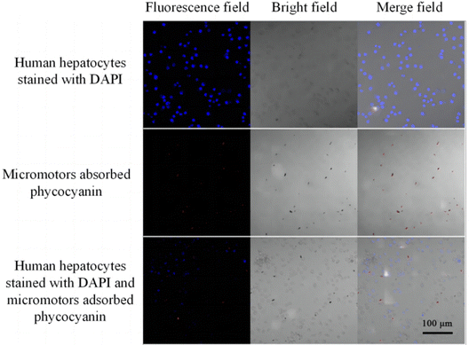
The cultured cell slides were removed, 20 μL of phycocyanin adsorbed micromotor solution was dropped, and 1 drop of DAPI staining was added to stain the cells. Then, the cells were observed under a laser confocal microscope at 20× to observe whether the micromotor still had fluorescence in the cellular environment. If so, then the micromotors can be applied not only in aqueous solutions but also maintain good properties in complex cellular environments, which lays a foundation for future in vivo experiments.
3. Results and discussion
3.1 Preparation of PEDOT/PSS–Pt–Ni–Zn imprinted micromotors
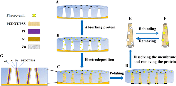
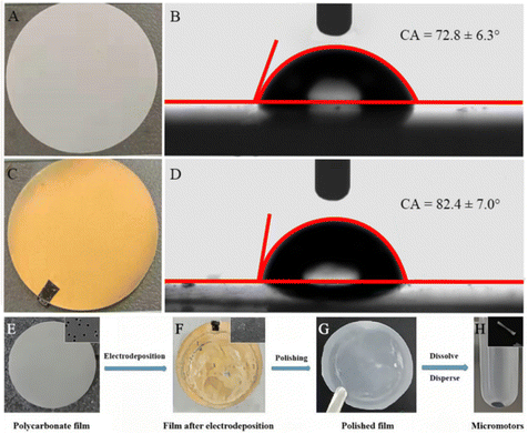
Micromotors were prepared by template electrodeposition, and the preparation principle is shown in Fig. 1. The polycarbonate film was initially sprayed with Au for 200 s, and its resistance was measured between 4 Ω and 15 Ω using a current meter. Meanwhile, the resistance of the non-sprayed polycarbonate film was measured to be infinite, indicating that the Au-sprayed film has electrical conductivity and can be used for electrodeposition. Fig. 2(A) and (C) show the polycarbonate films used for electrodeposition and the polycarbonate films sprayed with Au, respectively. At the same time, the contact angle of water droplets in contact with the substrate was recorded. As shown in Fig. 2(B) and (D), the contact angle of the non-sprayed polycarbonate film is 72.8°, indicating a certain degree of hydrophilicity. After spraying Au on the polycarbonate film, the Au nanoparticles become non-hydrophilic, resulting in a slight decrease in the hydrophilicity of the polycarbonate film. The contact angle increases to 82.4°. The entire synthesis of micromotors is represented in Fig. 2(E)–(H).The outermost layer of the micromotor synthesized according to the steps is the western blot layer, and its components are PEDOT/PSS. PEDOT is a polymer conductive material with good chemical and electrochemical stability, which is often used in electropolymerization. By doping a suitable proportion of PSS, the performance of PEDOT is further improved. In this manner, the complex has excellent film formation and stability, which is highly suitable for the blotting of protein targets. The main reason is that the PEDOT/PSS complex has a strong binding ability to proteins, which can produce necessary hydrogen bonds, electrostatic interactions, and π–π interactions with proteins.29,30 Therefore, PEDOT/PSS was selected as a protein imprinting layer. After the imprinting layer, the metal layers are Pt, Ni, and Zn, in which Pt was used as the skeleton of the micromotor, such that the micromotor has good mechanical properties. The electrodeposited solution can be found in Fig. S2 (ESI†). Ni makes the micromotor magnetic, such that its movement direction can be controlled by magnetism. Zn reacts under acidic conditions to produce bubbles that push the micromotor to move, making the micromotor motile.
3.2 Morphology of micromotors
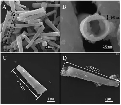
The morphology of micromotors with Pt deposition time of 200 s was observed under a microscope with 10× (Fig. S3(A), ESI†) and 40× (Fig. S3(B), ESI†) objective magnification. In the case of 10× objective magnification, the micromotors are dispersed well after ultrasonic vibration, and most of them are in a separate state. Given the small magnification and wide field of view, the micromotors are mostly short, black, and rod-like, but the micromotors may be broken and agglomerated due to the small amount of Pt deposition and the influence of subsequent incomplete polishing of polycarbonate film. Therefore, after the deposition amount of Pt layer was adjusted to 400 s to strengthen the skeleton of the micromotor, the morphology of the micromotor was observed under the 10× objective lens with an optical microscope after the ultrasonic oscillation and dispersion is uniform, as shown in Fig. S3(C) (ESI†). The fracture situation is greatly improved.SEM was used to further observe the morphology of the prepared micromotor. As shown in Fig. 3(A) and (B), the micromotor has a conical tubular structure, the outer diameter of the two ends of the tube is about 0.7 μm and 1.1 μm, and the thickness of the tube is about 160 nm. The length of the micromotors is not uniform, generally between 5–10 μm. This result can be attributed to the thickness of the polycarbonate film being affected and decreased during the polishing process, and the micromotors may break during the centrifugation process, leading to the reduction of the length. In addition, as shown in Fig. 3(C) and (D), the surface of the NIP is relatively smooth, whereas the surface of the imprinted micromotor is extremely rough. The reason is that the imprinted micromotor is immersed in phycocyanin solution before electrodeposition, and many protein-binding sites are formed on the surface of the imprinted micromotor. In comparison with the NIP, the binding ability and sensitivity to phycocyanin will be higher, which is beneficial to the recognition and capture of phycocyanin.
3.3 Composition of micromotors
The SEM analysis shows that the appearance morphology of the micromotor basically achieves the expected effect. To obtain direct evidence to further prove that the materials and elements in the electrodeposition of the template are successfully deposited and the micromotor is constructed, EDA was used to analyze the micromotor. The results are shown in Fig. S4 (ESI†). Particularly, Zn and Ni each have two spectral peaks in the energy spectrum diagram, which is mainly determined by the number of electron layers of the element. The more electron layers in the outer core of the element is, the more electronic transitions will occur, the more types of X-rays will be released, and the more spectral peaks will be finally reflected in the diagram. In addition, the spectrum peak of C in the figure is extremely low, but its content ranks the second among all the contents. Conversely, the spectrum peak of Zn is considerably higher than that of other elements, but its content is only slightly higher than that of C element. The reason is that the level of the spectrum peak represents the strength of the collected signal. Moreover, the energy released by the outer electron transition of different elements is also different, so the collected signal is also different. Therefore, no direct relationship exists between the number and level of spectral peaks of elements and their content.After software correction, the weight ratio and content ratio of each element were obtained. Particularly, C (27.07%) and O (18.16%) were mainly derived from the deposition of PEDOT/PSS in the outer western blot layer of the micromotor. Pt (1.04%), Ni (6.64%), and Zn (28.02%) were mainly derived from the deposition of metal elements in their corresponding electroplating solutions. Si (16.60%) and Au (2.47%) were the substrate elements. The reason for the appearance of Si is that the liquid micromotor solution was dried on the silicon wafer before electron microscopy, and the sample was pretreated. The reason for the appearance of Au is that the sample was sprayed with Au during electron microscopy. Therefore, the required substances and elements are successfully deposited and form the micromotor, and the amount of their content mainly depends on the length of the electrodeposition time or the amount of charge. In addition, the high Zn content deposited inside the micromotor ensures that it can react in an acidic environment, producing bubbles and then moving.
3.4 Magnetic property of micromotors
The micromotor in the centrifuge tube is initially adsorbed with a magnetic stick, as shown in Video S1 (ESI†). When the magnetic force bar is at different positions, the micromotor in the centrifuge tube will move along the direction of the magnetic force bar, which proves that the magnetic metal Ni is successfully deposited in the micromotor, and the artificial navigation system for the micromotor is constructed. Subsequently, 2 μL of the prepared micromotor liquid was dropped on the slide after ultrasonic oscillation. Under the optical microscope with 20× objective fold, the magnetic end of the micromotor in the ethanol liquid is attracted by the external magnetic field and shows controllable steering, as shown in Fig. 4(A)–(D). When the micromotor moves in an acidic environment, an external magnetic field can be applied to control its movement direction. In this manner, it can reach the intended position efficiently and accurately, and provide an accurate movement route for future in vivo delivery. See Video S2 (ESI†) for the video of magnetic guidance steering.3.5 Motion performance of micromotors
| Zn + 2H+ = Zn2+ + H2↑ | (1) |
To guarantee uninhibited bubble generation, a cover glass was not utilized on the slide. Thus, the solution on the slide was raised, which produced a stratification effect under the microscope. Different targets may float during bubble generation, making it blurred or even disappear under the field of view. The focal length should be adjusted for clear and precise tracking observation.
A 2 μL of 0.64 mol L−1 HCl (containing 2% Triton-X100) and 2 μL of micromotor solution were dropped on the slide and mixed. The pH of the mixed solution was about 1.0. Under the microscope at 20× objective, when the micromotor was immersed in the acid solution, the reaction is initially slow and then becomes fast until it stops. When the acid solution is only in contact with the micromotor, the contact area is small and the reaction is slow, which shows that bubbles are formed slowly at the end of the micromotor, and no movement occurs basically. When the acid solution enters the tube, the bubble generation rate is significantly accelerated, and the movement speed of the micromotor is also significantly improved. As the reaction proceeds, the micromotor shows a random curve motion, as shown in Fig. 4(E)–(I). The motor motion was analyzed, and its speed is directly related to the bubble generation rate, which depends on the solution pH and the contact area of the acid solution with the Zn layer. The movement life is mainly related to the thickness of Zn deposited in the inner layer and the pH of the acid solution. For example, as shown in the motion video of the micromotor in Video S3 (ESI†), the movement speed of the Zn-based micromotor with a length of 5 μm is about 100 μm s−1, and the life span is about 11 s. For the problem that the movement time of the acid-driven imprinted micromotor needs to be prolonged, it can be achieved by increasing the pore size of the polycarbonate film and increasing the amount of Zn deposition in the inner layer.
 | (2) |
According to formula (2), the average speed of micromotor movement is directly proportional to the unit mass of Zn (mZn), and is related to the length L of the micromotor, the bubble radius Rb, and the inner hole radius of the micromotor Rm. This formula indicates that multiple factors influence the movement of the micromotor, and its final speed is closely related not only to experimentally related parameters but also to the geometric dimensions of the micromotor's structure and the environmental conditions during movement.
Furthermore, under the condition of a fixed mass of Zn, with n being the experimentally measured hydrogen gas generation rate constant, it was measured as 8.6 × 10⁻⁴ m s−1, where the length of the micromotor (L) is 10 μm, and the inner radius of the tube (Rm) is 0.7 μm. When the mass of Zn is lower than a certain value, the radius of the generated bubbles (Rb) should be greater than the inner radius of the micromotor. The diameters are in good agreement with the relationship Rb = 1.2 Rm. Therefore, formula (2) can also be simplified as follows:
| vm = 9.12 × 10⁻³mZn | (3) |
According to formula (3), with other conditions unchanged, the mass of Zn and the speed of catalyzing the micromotor show a linear relationship. Further experimental results indicate that the maximum calculated movement speed of the micromotor is 100 μm s−1. The relevant experimental calculation results are in good agreement with the experimentally measured results, confirming the validity of this formula. Therefore, the movement speed of the micromotor can be fitted, predicted, and adjusted using the step–strain model.
3.6 Selective capture of phycocyanin by imprinted micromotors
On the basis of the above experimental verification, the acid-driven magnetic imprinting micromotor is successfully synthesized. To further verify the imprinting layer on the surface of the micromotor, 0.5 mg mL−1 of phycocyanin solution was added to the imprinting micromotor solution and the non-imprinting micromotor solution for 20 min. The reaction was observed under a laser confocal microscope. Given that the emission wavelength of phycocyanin was usually between 620 nm and 650 nm, the emission wavelength of 633 nm was selected. The red fluorescence can be seen clearly from Fig. 5(A), but the fluorescence image in Fig. S6(A) and (B) (ESI†) showed no observed fluorescence before co-incubation with phycocyanin solution, however, fluorescence was observed after 20 min incubation with 0.5 mg mL−1 phycocyanin solution in Fig. S6C (ESI†), which showed that the template proteins on the imprinted micro motors were removed before the co-incubation and successfully adsorbed phycocyanin after the incubation, indicating that the prepared micromotor can recognize and bind phycocyanin in water, and the water was then monitored. However, no red fluorescence corresponds to the micromotors in Fig. 5(B), which represents that the imprinted micromotors have successfully deposited the imprinted layer on the surface of the imprinted micromotors. In comparison with the NIPs, the micromotors imprinted with phycocyanin have better recognition and binding ability to phycocyanin, which is conducive to the adsorption of more phycocyanin, with high sensitivity and easy observation.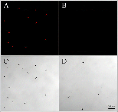 | ||
| Fig. 5 Laser confocal microscope images of micromotors after adsorbing phycocyanin: (A), (C) imprinted micromotors; (B), (D) NIPs. | ||
Some NIPs also produce red fluorescence. The main reason is that PEDOT/PSS is a substance that is easy to bind to proteins, and various interaction forces can be produced between PEDOT/PSS and proteins. In this manner, the protein can firmly bind to the outer layer of the micromotor PEDOT/PSS. PEDOT/PSS was also deposited on the NIP surface, so the NIPs may also have phycocyanin adsorbed on the surface and emit fluorescence. However, the selective adsorption and capture sensitivity of the imprinted micromotors for phycocyanin is still considerably better than that of the NIPs, which can adsorb more target proteins in a shorter time and at a lower concentration.
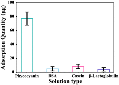
In the imprinted layer selectivity demonstration experiment, the measured data were analyzed to obtain the ratios of the four proteins after adsorption, as shown in Fig. 6. The concentration of phycocyanin solution after adsorption is 0.2229 mg mL−1, the amount adsorbed is 77.08 μg, the concentration of the BSA solution is 0.2949 mg mL−1, the amount adsorbed is 5.01 μg, the concentration of casein solution is 0.2853 mg mL−1, the amount adsorbed is 7.367 μg, the concentration of β-lactoglobulin solution is 0.2958 mg mL−1, and the amount adsorbed is 4.25 μg. Therefore, the recognition and adsorption of micromotors imprinted with phycocyanin is considerably higher than that of other proteins, which also proves that the imprinted layer is selective. Therefore, the combination of imprinting technology and micromotor actuation is feasible for the selective trapping of substances and load transport.
3.7 Application of phycocyanin-loaded micromotors in cellular environment
Micromotors attached to phycocyanin (single channel), DAPI-stained human hepatocytes (single channel), and a mixture of the two (double channel) were observed by laser confocal microscopy, as shown in Fig. 7. Human hepatocytes show blue fluorescence due to the reaction of the internal DNA with DAPI staining, and the shape is round. The micromotors show red fluorescence due to the adsorption of phycocyanin and has a long rod-like shape. The fluorescence of micromotors adsorbed with phycocyanin and stained cells can be successfully observed by mixing them together. Besides, we stored the micromotor in deionized water solution for two weeks, and then no Pt and Au were detected in the supernatant, indicating that this micromotor will not produce heavy metal leakage pollution during storage and use.Subsequently, in order to evaluate the potential toxicity of imprinted micromotor, we used the CCK-8 method to study the cytotoxicity of imprinted micromotors. As shown in Fig. S7 (ESI†), the survival rate of imprinted micromotors on human liver cells increased from 85.66% of the original concentration to 99.25% at 1000 times dilution, indicating that the external imprinting layer of the micromotor had relatively low cytotoxicity to cells and the toxicity of internal heavy metal ions was within a controllable range, it will not cause serious damage to the organism when acting inside the human body.
Thus, the micromotors can also be applied to complex cellular environments, in addition to the current widely used water environment, which is conducive to expanding the application scenarios and fields of micromotors and laying a certain foundation for in vivo drug delivery in the future.
4. Conclusion
In this study, on the basis of selective binding of PEDOT/PSS to proteins, acid-driven magnetic imprinting micromotors were successfully prepared by combining MIP with self-driven micromotors by template electrodeposition method. The micromotor has a tubular shape and strong magnetism, which can perform accurate magnetic guidance steering. In a strongly acidic environment, when the content of Triton X-100 is 2%, a large number of stable bubbles are generated, which drives the micromotor to move. In view of the strong fluorescence of phycocyanin, under the laser confocal microscope, the micromotor imprinted with phycocyanin can recognize and adsorb phycocyanin. The result demonstrates the high selectivity of imprinted micromotors, and the adsorption results can be easily observed. This result proves the feasibility and broad prospect of the combination of imprinting technology and micromotor driving technology in selective material loading and precise transport. In addition, the prepared micromotor contains metal Zn, which is one of the essential trace elements for the human body, and cytotoxicity experiments have shown that acid driven imprinted micromotors have no cytotoxicity. It is expected to be applied to the human stomach environment in the future.Author contributions
Guangdong Yang: methodology, data curation, writing original draft and editing. Jiajing Liu: data curation, writing original draft and editing. Zhong Zhang: conceptualization, writing reviewing, project administration, funding acquisition. Hongye Tian: writing reviewing. Li Yuan, writing reviewing. Xingbin Yang: project administration, funding acquisition.Conflicts of interest
There are no conflicts to declare.Acknowledgements
This work was funded by research grants including the National Key Research and Development Program of China (2022YFF1102200), the National Natural Science Foundation of China (31972183), the Open Project of China Food Flavor and Nutrition Health Innovation Center (CFC2023B-039), the Xi’an Advanced Manufacturing Technology and Key Project (21XJZZ0008) and the Fundamental Research Fund of the Central University (GK202206038).References
- W. Yang, J. Li, Z. Xu, J. Yang, Y. Liu and L. Liu, J. Mater. Chem. C, 2019, 7, 10297–10308 RSC.
- M. Zhou, T. Hou, J. Li, S. Yu, Z. Xu, M. Yin, J. Wang and X. Wang, ACS Nano, 2019, 13, 1324–1332 CAS.
- Y. Yang, K. Hu, P. Zhang, P. Zhou, X. Duan, H. Sun and S. Wang, Small, 2021, 17, 2100927 CrossRef CAS PubMed.
- D. Kagan, S. Campuzano, S. Balasubramanian, F. Kuralay, G.-U. Flechsig and J. Wang, Nano Lett., 2011, 11, 2083–2087 CrossRef CAS PubMed.
- Q. Wang, R. Dong, Q. Yang, J. Wang, S. Xu and Y. Cai, Nanoscale Horiz., 2020, 5, 325–330 RSC.
- V. de la Asunción-Nadal, D. Rojas, B. Jurado-Sánchez and A. Escarpa, J. Mater. Chem. A, 2023, 11, 1239–1245 RSC.
- C. C. Mayorga-Martinez, J. Vyskočil, F. Novotný and M. Pumera, J. Mater. Chem. A, 2021, 9, 14904–14910 RSC.
- G. Loget and A. Kuhn, Nat. Commun., 2011, 2, 535 CrossRef PubMed.
- D. Zhang, D. Wang, J. Li, X. Xu, H. Zhang, R. Duan, B. Song, D. Zhang and B. Dong, J. Mater. Sci., 2019, 54, 7322–7332 CrossRef CAS.
- X. Bing, X. Zhang, J. Li, D. H. L. Ng, W. Yang and J. Yang, J. Mater. Chem. A, 2020, 8, 2809–2819 RSC.
- W. Gao, X. Feng, A. Pei, Y. Gu, J. Li and J. Wang, Nanoscale, 2013, 5, 4696–4700 RSC.
- X. Chang, C. Chen, J. Li, X. Lu, Y. Liang, D. Zhou, H. Wang, G. Zhang, T. Li, J. Wang and L. Li, ACS Appl. Mater. Interfaces, 2019, 11, 28507–28514 CrossRef CAS PubMed.
- W. Gao, A. Pei, R. Dong and J. Wang, J. Am. Chem. Soc., 2014, 136, 2276–2279 CrossRef CAS PubMed.
- W. Gao, A. Uygun and J. Wang, J. Am. Chem. Soc., 2011, 134, 897–900 CrossRef PubMed.
- R. F. Ismagilov, A. Schwartz, N. Bowden and G. M. Whitesides, Angew. Chem., Int. Ed., 2002, 41, 652–654 CrossRef CAS.
- W. F. Paxton, K. C. Kistler, C. C. Olmeda, A. Sen, S. K. St. Angelo, Y. Cao, T. E. Mallouk, P. E. Lammert and V. H. Crespi, J. Am. Chem. Soc., 2004, 126, 13424–13431 CrossRef CAS PubMed.
- J. Li, S. Sattayasamitsathit, R. Dong, W. Gao, R. Tam, X. Feng, S. Ai and J. Wang, Nanoscale, 2014, 6, 9415–9420 RSC.
- S. Giudicatti, S. M. Marz, L. Soler, A. Madani, M. R. Jorgensen, S. Sanchez and O. G. Schmidt, J. Mater. Chem. C, 2014, 2, 5892–5901 RSC.
- A. Zenerino, C. Peyratout and A. Aimable, J. Colloid Interface Sci., 2015, 450, 174–181 CrossRef CAS PubMed.
- C. E. Sing, L. Schmid, M. F. Schneider, T. Franke and A. Alexander-Katz, Proc. Natl. Acad. Sci. U. S. A., 2009, 107, 535–540 CrossRef PubMed.
- W. Wang, S. Li, L. Mair, S. Ahmed, T. J. Huang and T. E. Mallouk, Angew. Chem., Int. Ed., 2014, 53, 3201–3204 CrossRef CAS PubMed.
- O. E. Shklyaev, H. Shum, V. V. Yashin and A. C. Balazs, Langmuir, 2017, 33, 7873–7880 CrossRef CAS PubMed.
- L. Chen, X. Wang, W. Lu, X. Wu and J. Li, Chem. Soc. Rev., 2016, 45, 2137–2211 RSC.
- J. Orozco, A. Cortés, G. Cheng, S. Sattayasamitsathit, W. Gao, X. Feng, Y. Shen and J. Wang, J. Am. Chem. Soc., 2013, 135, 5336–5339 CrossRef CAS PubMed.
- N. T. Eriksen, Appl. Microbiol. Biotechnol., 2008, 80, 1–14 CrossRef CAS PubMed.
- Z. Zhang, L. Chen, F. Yang and J. Li, RSC Adv., 2014, 4, 31507–31514 RSC.
- D. Hu, Z. Zhang, L. Yuan, W. Li, Y. Guo, R. Zhang, X. Yang and H. Peng, Int. J. Biol. Macromol., 2021, 193, 127–136 CrossRef CAS PubMed.
- Z. Zhang, J. Li, L. Fu, D. Liu and L. Chen, J. Mater. Chem. A, 2015, 3, 7437–7444 RSC.
- A. Menaker, V. Syritski, J. Reut, A. Öpik, V. Horváth and R. E. Gyurcsányi, Adv. Mater., 2009, 21, 2271–2275 CrossRef CAS.
- G. Lautner, J. Kaev, J. Reut, A. Öpik, J. Rappich, V. Syritski and R. E. Gyurcsányi, Adv. Funct. Mater., 2010, 21, 591–597 CrossRef.
- M. García, J. Orozco, M. Guix, W. Gao, S. Sattayasamitsathit, A. Escarpa, A. Merkoçi and J. Wang, Nanoscale, 2013, 5, 1325–1331 RSC.
Footnotes |
| † Electronic supplementary information (ESI) available. See DOI: https://doi.org/10.1039/d3tb02021e |
| ‡ Contributed equally to this work. |
| This journal is © The Royal Society of Chemistry 2023 |

