 Open Access Article
Creative Commons Attribution 3.0 Unported Licence
High-entropy materials for electrochemical energy storage devices
Jie
Qu
 ,
Mark A.
Buckingham
 and
David J.
Lewis
 *
*
Department of Materials, The University of Manchester, Oxford Road, Manchester M13 9PL, UK. E-mail: david.lewis-4@manchester.ac.uk
First published on 21st September 2023
Abstract
Single phased, high-entropy materials (HEMs) have yielded new advancements as energy storage materials. The mixing of manifold elements in a single lattice has been found to induce synergistic effects leading to superior physicochemical properties. In this review, we summarize recent advances of HEMs in energy storage applications such as metal-ion batteries, supercapacitors, and fuel cells. We begin with defining HE materials (HEMs) and discussion of the synthetic methods and characterization techniques appropriate for evaluating HEMs at various length scales. We also discuss the application of a wide variety of HEMs, including HE alloys, oxides, chalcogenides, Prussian blue analogues, and sodium super ionic conductor (NASICON) materials in energy storage systems. Finally, advantages, challenges, and future perspectives of HEMs in energy storage systems are discussed.
Introduction
In the future, generating usable energy from renewable sources such as solar, hydroelectric, and wind are expected to replace conventional fossil fuels due to their limited reserves and resultant impact issues.1–3 However, most sources of renewable energy are intermittent, for example, solar panels generate no power at night, which is problematic to maintaining constant energy supplies required for large-scale grid applications. Hence, the development of electrical energy storage systems are of great interest to enabling renewable power generation, coupled with energy stability.4,5 Among them, electrochemical energy storage (EES) systems such as batteries and supercapacitors have been largely used in electrical devices such as electrical vehicles, mobile phones, and laptops, but their limited energy density and cycling capability have stymied widespread development.6–9To solve these issues, the development of energy storage materials with satisfactory electrochemical performances is key. Recently, high-entropy materials (HEMs) have garnered much attention in this space. HEMs were first manifested as high-entropy alloys (HEA) in 2004,10,11 consisting of a single-phased, multicomponent solid solution with at least five principal elements in near-equimolar concentrations. The compositional complexity bestows HEAs with emergent properties, including entropy stabilization, lattice distortion, sluggish diffusion and the so-called “cocktail effect”.12 In entropy stabilization, the high configurational entropy within these materials compensates for the enthalpic requirements of structural stabilization. Lattice distortion is caused by atoms with different crystal radii randomly occupying the positions in the lattice of the HEA. A wide range of physiochemical properties such as mechanical, thermal, and electrical behaviors can be conferred by introducing various elements. Sluggish diffusion results from lattice distortion, giving rise to restricted diffusion kinetics within the material. Due to the incorporation of multiple elements in a single phase, with each one playing a critical role in determining the structural properties, the combinatorial and synergistic properties result in the ‘cocktail effect’, leading to, among others, significantly enhanced catalysis. The concept of HEAs was later extend to other high-entropy (HE) systems such as HE oxides,13–17 chalcogenides,18–20 borides,21–24 carbides,25–28 nitrides,29–31 silicides,32,33 phosphides/phosphates,34–36 fluorides,37–39 NASICON-types40–42 and Prussian blue analogues.43–45 These HEMs with their interesting and often unexpected properties are expected to be promising active materials for electrochemical energy storage systems.
In this review, we summarize the recent progress on the HEMs related to their electrochemical energy storage applications. Firstly, the concept of HEMs will be introduced. Then, synthetic methods and characterization techniques will be summarized. Next, we provide a review of the reported applications of HEMs in electrochemical energy storage devices, including Li-ion, Na-ion, Li–S, and Zn-ion batteries, supercapacitors, and fuel cells. Overall, this review aims to provide an overview of the wide range of functional HEMs for electrochemical energy storage systems and pinpoint the existing challenges and future directions in this field.
Theoretical concept of HEMs
The general high entropy concept was first introduced by Cantor et al. and Yeh et al. based on the configurational entropy of mixing multiple principal elements with near-equimolar ratios.10,47 For HEAs, the high entropy term refers to alloys which contain at least five elements in atomic percentages ranging from 5% to 35%. The state of ‘high entropy’ may then be quantified by the simple entropy of mixing: | (1) |
 | (2) |
 (where A represents alkali metal ions (e.g., Na+ and K+), and M and
  correspond to transition metal cations).53 Due to the conflicting definition of high entropy across multiple materials, we propose a universal criterion to classify HEMs by the number of elements with a singly disordered lattice (or sub-lattice), which needs to be five or higher, with molar fractions of each component greater than 5%. It is worthwhile to note that for inorganic materials with multiple disordered sub-lattices, such as the HE chalcogenide (PbSnSb)(SSeTe), it is possible to achieve a configurational entropy value of 1.5R54 even without five principle elements in a disordered sub-lattice.
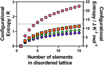 | ||
| Fig. 1 Calculated configurational entropy (in both R and J K−1 mol−1) for species with a single disordered sub-lattice (M) for (pink circles) alloys with a single lattice, and a range of common metal chalcogenide materials with a single chalcogenide sub-lattice (i.e. X is all O, S, Se or Te) for (orange squares) MX, (blue diamonds) M2X3 and (purple hexagons) MX2. Copyright permission from Royal Society Chemistry, used from ref. 46. | ||
Synthetic methods and techniques to characterize HEMs
Various physical and chemical synthetic methods have been developed to successfully fabricate HEMs with a single phase and homogenous elemental distributions. Classical solid state reaction is a common method to prepare HEMs, which involves several processing steps including pre-annealing mixing, such as mechanical ball milling to produce an even elemental mixture, followed by high-temperature calcination.55–58 Generally, re-mixing and re-calcination steps are also required to further improve the elemental homogeneity in the final HEM. One drawback of this method is that the particle size of the solid-state reagents are around 100 nm, even after ball-milling, which inhibits elemental mixing at the nanoscale prior to the annealing process, which leads to the requirement of energy-intensive (usually above 1000 °C)56 and time-consuming (generally between 10 h and 24 h)59 procedures to ensure sufficient elemental diffusion at the nanoscale. High energy ball milling has recently been reported to produce a series of HE chalcogenides, which is performed at room temperature and does not require any external heating. However, this method requires a pre-synthetic step to produce each metal sulfide and an extended process time for ball milling, up to 120 h in total, which could potentially preclude scale up.60Another common synthetic route towards HEMs is solvothermal synthesis, where precursors react in an organic solvent in an autoclave. This approach has the advantage of relatively low reaction temperatures (usually between 160 °C and 200 °C).61–63 In addition, the morphology of the final product can be controlled by adjusting the reaction temperature and reagent concentrations. Bondesgaard et al. reported a facile and low-temperature solvothermal synthesis method to fabricate the high entropy alloy Pt0.20Pd0.20Ir0.20Rh0.20Ru0.20 by dissolving metal acetylacetonate precursors in an acetone-ethanol mixture solvent.64 They found that the choice of reagent precursors and solvent is crucial to produce HEMs. The relatively large metal-acetylacetonate binding constant can significantly promote coprecipitation, which is beneficial to alloy formation.
Cation exchange methods have been reported to synthesize a nanoscale HE metal sulfide (HEMS).65 As shown in Fig. 2, Schaak et al. used pre-fabricated roxbyite copper sulfide (Cu1.8S) nanoparticles, which were then suspended in solutions that contain appropriate amount of various metal chlorides to be exchanged with Cu to form (ZnCoCuInGa)S HEMS nanoparticles. The mixture reacts initially at 110 °C under a vacuum for 30 mins and is then heated to 180 °C under Ar for another 30 min. Subsequently, the temperature of the reaction mixture decreases to 140 °C and is held for a further 30 min. After cooling to room temperature, the reaction mixture is centrifuged with a 1![[thin space (1/6-em)]](https://www.rsc.org/images/entities/char_2009.gif) :
:![[thin space (1/6-em)]](https://www.rsc.org/images/entities/char_2009.gif) 1 mixture of IPA and acetone. This method is entropically favorable as the cation exchange reacts in solution, which is advantageous to the formation of HEMs. However, this approach is potentially unscalable as the relatively slow diffusion rate (we estimate ca. 115 days to diffuse 100 μm) would preclude bulk HEMS formation.46
1 mixture of IPA and acetone. This method is entropically favorable as the cation exchange reacts in solution, which is advantageous to the formation of HEMs. However, this approach is potentially unscalable as the relatively slow diffusion rate (we estimate ca. 115 days to diffuse 100 μm) would preclude bulk HEMS formation.46
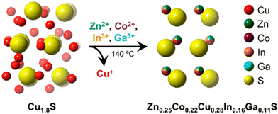 | ||
| Fig. 2 Figure visually showing the formation of (Zn0.25Co0.22Cu0.28Ln0.16Ca0.11)S HE metal sulfide synthesis via simultaneous multication exchange. Copyright permission from American Chemical Society, used from ref. 65. | ||
A very effective synthetic route towards HEMs is via molecular precursors.66–68 This method has significant advantages over other synthetic techniques, including homogenous mixing of the precursors at the atomic scale, which maximizes the disorder and thus entropic stabilisation in the solid-state products, prefabricated M-S bonds in the precursors which enable relatively reduced synthetic times (1–5 h) and relatively low preparation temperatures (300–500 °C) compared to other synthetic approaches.69 Lewis and co-workers pioneered this route to successfully prepare bulk HE lanthanide oxysulfide materials based on the thermal decomposition (900 °C for 5 h) of five lanthanide dithiocarbamate precursors.66 Lewis and co-workers also reported the synthesis of quantum confined (HE) lanthanide oxysulfide nanoparticles.67 This method utilizes solvothermal decomposition of lanthanide dithiocarbamate precursors in the presence of capping agents. The obtained HE nanoparticles had identical elemental composition to that of the bulk HE oxysulfides. Recently, a novel 2D HE metal dichalcogenide (MoWReMnCr)S2 has been fabricated via a combination of ‘bottom-up’ and ‘top-down’ approaches.67 The bulk HE material was initially synthesized through solventless thermolysis of a mixture of five individual metal dithiocarbamate precursors at 500 °C for 1 h. The structural similarity between the as-prepared HE disulfide and layered 2H-MoS2 enabled liquid-phase exfoliation to extract few layered HE (MoWReMnCr)S2 nanosheets (3–7 atomic layers). The few layered nanosheets produced were found to contain a homogeneous elemental distribution of metals at the atomic scale. Overall, these approaches are potentially extendable to the synthesis of manifold HE chalcogenides due to the wide library of available transition, main group, and lanthanide single source precursors.70 In addition, the ternary transition-metal dichalcogenides Mo1−xWxS2 or transition-metal oxides Mo1−xWxO3 have been previously produced via single source precursors simply by changing the decomposition atmosphere,71 this approach can therefore potentially be extended to the synthesis of HE oxides.
A variety of material characterization techniques can be utilized to deduce HEMs crystal structures, morphologies, elemental distribution, and electronic structures. X-ray diffraction (XRD) is a typical method to characterize the HEM crystal structure, which provides a direct assessment of the phase purity of HEMs.39 The refined lattice parameters, crystallinity, particle size, and orientation can also be calculated from diffraction data. Scanning electron microscopy (SEM) and transmission electron microscopy (TEM) are frequently used to observe the surface morphologies and particle dimensions of HEMs in the micro-to-nano scales.65,75 High-angle annular dark-field – scanning transmission electron microscopy (HAADF-STEM) coupled with fast Fourier transform (FFT) analysis can reveal the atomic arrangements, lattice planes, grain boundaries, and dislocations in the structure at nano-to-atomic scale.76 Yong-sheng et al. applied HAADF-STEM to characterize the atomic-scale structure of the HE perovskite Na(Ni0.25Mg0.05Cu0.1Fe0.2Mn0.2Ti0.1Sn0.1)O2 (HEO424).72 As shown in Fig. 3(a) and (b), both Na(Ni0.4Fe0.2Mn0.4)O2 (NFM424) and HEO424 show dense structures without grain boundaries, indicating that both samples are a single crystal. Atomic-resolution HAADF-STEM imaging of a HEO424 particle reveals an hexagonally symmetrical arrangement of metals, which is in accordance with imaging down the [001] zone axis. HAADF-STEM used in tandem with energy-dispersive X-ray (EDX) spectroscopy is a powerful tool to confirm the homogenous elemental distribution at near-to atomic scale and discover whether phase separation exists in HEMs or not. Chen et al. applied HAADF-STEM elemental mapping to confirm the formation of a heterostructure between an high–entropy oxide and CuCeOx73 As shown in Fig. 3(c), the Ce ions did not mix with the bulk HEO solid solution but was grafted onto the surface of the HEO particles. It is interesting to note that Ni, Mg, and Co elements are much diluted in this area compared to that in the core structure, while Cu and Zn elements dissolve with Ce, which indicates that Cu and Zn are incorporated in the CeO2 lattice to form a (CuZnCe)O2 solid solution on the shell of the HEO.
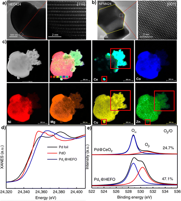 | ||
| Fig. 3 TEM and HAADF-STEM images of NaNi0.4Fe0.2Mn0.4O2 (a) and NaNi0.25Mg0.05Cu0.1Fe0.2Mn0.2Ti0.1Sn0.1O2. (b) Copyright permission from American Chemical Society, used from ref. 72. (c) Elemental maps and high-resolution HAADF-STEM image results for CuCeOx–(NiMgCuZnCo)O with 20 mol% Ce. Copyright permission from Elsevier, used from ref. 73. (d) XANES spectra at the Pd K-edge and (e) XPS profiles of O 1s for Pd@HEFO and Pd@CeO2. Copyright permission from Springer Nature, used from ref. 74. | ||
X-ray photoelectron spectroscopy (XPS) is a tool to analyze chemical environments within a material, including the valence states and multielement compositions on the surface of HEMs.77,78 When coupled with X-ray absorption near-edge structure (XANES), it can fundamentally reveal the electronic structure and coordination states of multiple elements in HEMs structure. For example, Xu et al. used XANES and XPS measurements in tandem to investigate the chemical surroundings of single Pd atoms in (CeZrHfTiLa)Ox for CO oxidation catalysis.74 As shown in Fig. 3(d), the Pd K-edge absorption edge spectrum for Pd1@HEFO is between that of Pd foil and PdO, suggesting that the valence state of Pd is between 0 and +2. The valence state obtained by XANES is lower than the +4 from XPS, which is possibly related to the surface oxidation between Pd atoms and air. In addition, the O 1s XPS spectra shows that the ratio of absorbed oxygen (Oβ) to the lattice oxygen (Oα) in Pd1@HEFO is much higher than that of Pd@CeO2 (Fig. 3(e)), which might be ascribed to the fact that the Pd incorporation in HEFO generates more oxygen vacancies. Also, the formation of more oxygen vacancies is consistent with its improved catalytic activity.
HEMs for energy storage systems
With the limited resources of fossil fuels and their related environmental issues, the rapid development of alternative energy sources is required.79–81 This will include energy harvesting from waste materials and energy storage devices.82–84 Electrochemical energy storage systems have advantages in sustainability and stable energy output. Batteries, supercapacitors, and fuel cells are examples of energy storage technologies.85 All these devices consist of two electrodes and an electrolyte.86 In batteries and fuel cells, the chemical energy derived from redox reactions at the two electrodes converts chemical potential to electrical power.87 The electrode with lower potential is designated as the anode and the cathode has a relatively higher potential. The major difference between batteries and fuel cells is the energy storage and conversion locations.88 For batteries, the anode and cathode are not only the charge-transfer mediums, but are also active in the redox reactions. Batteries are therefore closed systems where the energy storage and conversion occur within the electrode materials. For fuel cells, the species participating in the redox reactions are supplied externally e.g., air or a redox reservoir, where the energy storage and conversion are initiated independently. In supercapacitors, energy is not generated by the redox reactions, the electrical energy is stored and released by reversible adsorption and desorption of electrolyte between two electrostatic double layers (EDLs) formed by the electrode/electrolyte interface.89 As there is no chemical reaction involved, the physical charging mechanism from electrostatic attraction alone enables supercapacitors to have rapid charge–discharge kinetics, cycling durability, and high-power densities.The Ragone plot (Fig. 4) shows that fuel cells can be characterized by their high energy densities, while supercapacitors are characterized by their high power output.90 Batteries have intermediary power output and energy storage compared to fuel cells and supercapacitors, with supercapacitors having a low energy density but high power density. Indeed, battery electrodes with high surface areas exhibit similar characteristics to that of supercapacitors,91–93 where the redox reaction partly contributes to the energy storage, which results in the higher energy densities compared to conventional supercapacitors. At the same time, similar electrochemical storage mechanisms to EDL supercapacitors allow the delivery of better power density compared to batteries. Due to this synergistic effect, the design of hybrid electrochemical storage systems is of interest as they are capable of displaying high energy and power densities in comparison to EDL supercapacitors and batteries alone.
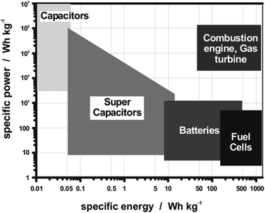 | ||
| Fig. 4 Ragone plot of the energy density (W h kg−1) and power density (W kg−1) realms for the different electrochemical energy storage systems and conventional capacitors. Copyright permission from American Chemical Society, used from ref. 88. | ||
In recent years, HEMs have been widely applied as electrode materials for electrochemical energy storage systems.94–96 Due to their complicated compositions, HEMs often exhibit excellent properties that traditional materials cannot access easily, such as superionic conductivity,97 high reversible capacity26,98 and extended cycle life.99 To date, a wide variety of HEMs including HE metal alloys,100–102 oxides,14,96,103 chalcogenides,60 perovskites,104–107 Prussian blue analogues44 and NASICON-type materials42 have showed extraordinary performances in metal-ion batteries,15,108–110 supercapacitors102 and fuel cells.111
HEMs for lithium-ion batteries (LIBs)
Previous studies have shown that HEMs have excellent performance as both anode and cathode materials for LIBs.14,95,98,99,112 Owing to the structural stability conferred by entropic stabilization, the materials are more robust with respect to the charging/discharging processes when compared to traditional electrode materials. Furthermore, the introduction of electroactive cations with high redox reaction potentials, such as Ni and Fe, is effective for enhancing specific capacity as well as energy density.99 Recent reported HEMs as electrode materials for LIBs are summarized in Table 1.| HEMs | Synthetic method | Structure | Electrochemical performance | Capacity retention | Ref. |
|---|---|---|---|---|---|
| (Co0.2Ni0.2Mn0.2Zn0.2Fe0.2)3O3.2 | High-energy ball milling | Rock salt | 600 mA h g−1 after 200 cycles | 83.5% after 45 cycles | 113 |
| (NiMnCrCoFe)3O4 | Hydrothermal reaction | Spinel-type | 527 mA h g −1 at 5 A g−1 current density | 99.8% after 300 cycles | 114 |
| (Mg0.2Co0.2Ni0.2Cu0.2Zn0.2)O | High-energy ball milling | Rock salt | 660 mA h g−1 at 100 mA g−1 current density | 80% after 300 cycles | 115 |
| (FeMnCrCoZn)3O4 | Co-precipitation method | Spinel-type | 548 mA h g−1 at 100 mA g−1 current density | — | 116 |
| (a) (MgFeCoNiZn)O (b) (TiFeCoNiZn)3O4 | High-temperature sintering | (a) Rock salt | 548 mA h g−1 and 478 mA h g−1 at 50 mA g−1 current density, respectively. | 86% after 300 cycles | 116 |
| (b) Spinel-type | |||||
| Zn0.5Co0.5Mn0.5Fe0.5Al0.5Mg0.5O4 | Co-precipitation method | Spinel-type | 290 mA h g−1 at 2 A g−1 current density | 81% after 5000 cycles | 117 |
| LiNi0.2Mn0.2Co0.2Fe0.2Al0.2O2 | High-temperature sintering | Layered oxide | 200 mA h g−1 at 18 mA g−1 current density | 94.8% after 50 cycles | 118 |
| (FeCoCrMnZn)3O4 | Ball milling | Spinel-type | 829 mA h g−1 at 2 A g−1 current density | 88% after 2000 cycles | 112 |
| (YDyCeNdLa)2Sn2O7 | Co-precipitation method | Pyro-chlore phase | 396 mA h g−1 at 0.1 A g−1 current density | ∼100% after 100 cycles | 119 |
| Li6.4La3Zr0.4Ta0.4Nb0.4Y0.6W0.2O12 | High-temperature sintering | Garnet-type | 154 mA h g−1 at 17 mA g−1 current density | 97% after 5 cycles | 120 |
| (Mg0.2Cr0.2Mn0.2Fe0.2Co0.2)3O4 | Microwave-assisted method | Spinel-type | 875 mA h g−1 at 1 A g−1 current density | 87% after 1000 cycles | 121 |
| Mg0.2Co0.2Ni0.2Cu0.2Zn0.2O | High-temperature sintering | Rock salt | 700 mA h g−1 at 100 mA g−1 current density | — | 122 |
| Co0.2Cu0.2Mg0.2Ni 0.2Zn0.2)O | Hydrothermal method | Rock salt | 401 mA h g−1 at 0.5 A g−1 current density | 90% after 3200 cycles | 123 |
| (Cr0.2Fe0.2Co0.2Ni0.2Zn0.2)3O4 | Sol–gel method | Spinel-type | 1022 mA h g−1 at 1 A g−1 current density | 96% after 1000 cycles | 124 |
| LiCr1/5Mn1/5Fe1/5Co1/5Ni1/5O2 | Solution combustion synthesis | Rock-salt | 218 mA h g−1 at 20 mA g−1 current density | 51% after 25 cycles | 125 |
| (FeCoNiCrMn)3O4 | Ball milling | Spinel-type | 597 mA h g−1 at 2 A g−1 current density | 86.2% after 1200 cycles | 126 |
| (CrMnFeNiCu)3O4 | Hydrothermal method | Spinel-type | 340 mA h g−1 at 2 A g−1 current density | 87.8% after 150 cycles | 127 |
| (Mg0.2Co0.2Ni0.2Cu0.2Zn0.2)O | Solvothermal Method | Rock-salt | 480 mA h g−1 at 20 mA g−1 current density | 86.5% after 300 cycles | 48 |
| (LiMgCoNiCuZn)O | Molten salt method | Rock-salt | 714 mA h g−1 at 0.1 A g−1 current density | 83% after 300 cycles | 128 |
| Mg0.2Co0.2Ni0.2Cu0.2Zn0.2O | Electrospinning method | Rock-salt | 365 mA h g−1 at 2 A g−1 current density | 82.8% after 200 cycles | 129 |
| (CrNiMnFeCu)3O4 | Hydrothermal method | Spinel-type | 480 mA h g−1 at 2 A g−1 current density | 95% after 500 cycles | 130 |
| (Mg0.2Co0.2Ni0.2Cu0.2Zn0.2)O | High-temperature sintering | Rock-salt | 1225 mA h g−1 at 0.1 A g−1 current density | 81.7% after 1000 cycles | 131 |
| (Co0.2Cr0.2Fe0.2Mn0.2Ni0.2)3O4 | Solution combustion synthesis | Spinel-type | 428 mA h g−1 at 10 A g−1 current density | 99% after 250 cycles | 132 |
| (CrMnFeNiCu)3O4 | Hydrothermal method | Spinel-type | 913 mA h g−1 at 50 mA g−1 current density | 83% after 400 cycles | 133 |
| (Mg,Co,Ni,Cu,Zn)O | High-temperature sintering | Rock-salt | 489 mA h g−1 at 0.1 A g−1 current density | 77% after 100 cycles | 134 |
| (CrMnFeCoNi)3O4 | Hydrothermal method | Spinel-type | 1225 mA h g−1 at 20 mA g−1 current density | 91% after 200 cycles | 135 |
| (Mg, Cu, Ni, Co, Zn)O | Microwave-assisted method | Rock-salt | 686 mA h g−1 at 0.1 A g−1 current density | ∼100% after 1000 cycles | 136 |
| (Al0.2CoCrFeMnNi)0.58O4−d | Solution combustion synthesis | Spinel-type | 554 mA h g−1 at 0.2 A g−1 current density | 71% after 500 cycles | 137 |
| Mg0.2Co0.2Ni0.2Cu0.2Zn0.2O | High-temperature sintering | Rock-salt | 600 mA h g−1 at 0.1 A g−1 current density | — | 138 |
| (Ni0.2Co0.2Mn0.2Fe0.2Ti0.2)3O4 | High-temperature sintering | Spinel-type | 594 mA h g−1 at 0.05 A g−1 current density | ∼100% after 100 cycles | 139 |
| (Cr0.2Mn0.2Fe0.2Co0.2Ni0.2)3O4 | Hydro-thermal method | Spinel-type | 500 mA h g−1 at 2 A g−1 current density | 90% after 200 cycles | 140 |
| (FeCoNiCrMn)3O4 | High-temperature sintering | Spinel-type | 182 mA h g−1 at 2 A g−1 current density | 81% after 300 cycles | 141 |
| (MgCoNiZn)1−xLixO | High-temperature sintering | Rock-salt | 610 mA h g−1 at 1 A g−1 current density | 31.2% after 130 cycles | 142 |
| (Mg0.2Ti0.2Zn0.2Cu0.2Fe0.2)3O4 | High-temperature sintering | Spinel-type | 272 mA h g−1 at 2 A g−1 current density | 78% after 300 cycles | 143 |
| [(Bi,Na)0.2(La,Li)0.2(Ce,K)0.2Ca0.2Sr0.2]TiO3 | High-temperature sintering | Pbnm (62) space group | 70 mA h g−1 at 3 A g−1 current density | ∼100% after 300 cycles | 144 |
| (Co0.2Cu0.2Mg0.2Ni0.2Zn0.2)O | Nebulized spray pyrolysis | Rock-salt | 950 mA h g−1 at 0.02 A g−1 current density | 94% after 100 cycles | 145 |
| (Co0.2Cu0.2Mg0.2Ni0.2Zn0.2)O | Nebulized spray pyrolysis | Rock-salt | 446 mA h g−1 at 1.6 A g−1 current density | 67% after 50 cycles | 98 |
| (Mg0.2Co0.2Ni0.2Cu0.2Zn0.2O) | High-temperature sintering | Rock-salt | 920 mA h g−1 at 0.1 A g−1 current density | 58% after 300 cycles | 99 |
| Li1.3Mn0.1Co0.1Mn0.1Cr0.1Ti0.1Nb0.2O1.7F0.3 | High-temperature sintering | — | 170 mA h g−1 at 2 A g−1 current density | 66% after 19 cycles | 146 |
| Lix(Co0.2Cu0.2Mg0.2Ni0.2Zn0.2)OFx | High-temperature sintering | Rock-salt | 161 mA h g−1 at 20 mA g−1 current density | 71% after 300 cycles | 147 |
| (FeNiCoMnCr)S2 | High-energy ball milling |
Pa![[3 with combining macron]](https://www.rsc.org/images/entities/char_0033_0304.gif) |
716 mA h g−1 at 2.5 A g−1 current density | 67% after 200 cycles | 148 |
Among HEMs, rock-salt and spinel-type HE oxides have been most widely applied as electrode materials for LIBs.14,95,140 Transition metal oxides (TMOs) are promising electrodes for LIBs as they have higher operating voltages compared to graphite-based materials.149 Most TMO electrodes follow the conversion reaction mechanism: MxOy + 2yLi+ + 2ye− ↔ yLi2O + xM,150,151 which possesses higher theoretical specific capacities in comparison to intercalation-type electrodes152 as more electrons involved in the reaction. The HEO rocksalt-type (Mg0.2Co0.2Ni0.2Cu0.2Zn0.2)O was first utilized as an anode for LIBs.14 In comparison to conventional LIB electrodes, the HEO exhibits significantly improved rate capability, even when cycling at high current densities. It is worthwhile to note that various crystallographic structures and emergent properties are obtained via compositional adjustment between multi-metallic cations and anions. For example, spinel HEO anodes (Mg0.2Ti0.2Zn0.2Cu0.2Fe0.2)3O4 and (Ni0.2Co0.2Mn0.2Fe0.2Ti0.2)3O4 have also been developed, with the former showing superior specific capacity of 1235 mA h g−1 with excellent retention of 90% after 200 cycles.140 The electrochemically active Ni and Co in the lattice enable the entropy-stabilized HEO to perform redox reactions during charge/discharging processes, which confers a higher reversible capacity. Electrochemically inert cations, such as Mg2+ and Zn2+, could play a critical role in stabilizing HEOs structure during charging/discharging processes and lead to extraordinary cycling performance. Thus, the multi metallic cations in the HEO collectively contribute to the superior electrochemical performances observed.
Due to the incorporation of various metallic cations in entropy-stabilized single-phase HEOs, the elemental interactions may lead to more complex lithiation behaviors compared to traditional metal oxides with one or two metallic cations. Feng et al. employed in situ electron diffraction (ED) and ex situ high-resolution transmission electron microscopy (HR-TEM) imaging to atomically identify phase transformations during the whole lithiation process of a rock-salt HEO electrode (Co0.2Ni0.2Mn0.2Zn0.2Fe0.2)3O3.2 (M3O3.2).113 The pristine ED pattern (Fig. 5(a)) of the HEO electrode shows eight distinct diffraction rings which were indexed to the rock-salt structure (ICDD PDF#01-078-0431). At the initial lithiation stage, an emerging reflection from the Li2O (220) plane was generated. The eight sharp diffraction rings in Fig. 5(a) gradually vanish and the HEO (311) reflection completely disappeared in Fig. 5(b). Ni, Co, and Mn metal phases also appear sequentially (Fig. 5(c)–(e)). The diffraction intensities of M3O3.2 were further weakened and the (422) and (400) reflections vanish. At the final lithiation stage (Fig. 5(f)), the pristine rock-salt structure is not observed. A new phase of Li0.2Zn0.8 with two distinguishable (100) and (101) planes was generated. As shown in Fig. 5(g), the quantitative intensity profiles from time-sequenced ED patterns are plotted to better visualize the structural transformations throughout the lithiation process, the characteristic peaks attributed to the HEO rock-salt phase vanishes, while some broad new peaks indexed as Fe, Ni, Co, Mn, and Li0.2Zn0.8 appeared in succession, which is highly consistent with the time-sequenced ED patterns. To further verify the formation of these emerging crystallites, the M3O3.2-based half cells discharged to 0.01 V were disassembled and then were characterized by TEM. As shown in Fig. 5(h)–(l), HRTEM images and their corresponding fast Fourier transformation (FFT) also confirm the occurrence of these new phases. Thus, the detailed in situ and ex situ TEM observations suggest that HEO anode undergoes complicated conversion and alloying reactions during the lithiation process, and this results in a polycrystalline structure consisting of Fe, Ni, Co, Mn, Li0.2Zn0.8 and Li2O phases.
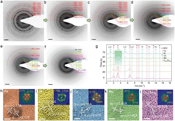 | ||
| Fig. 5 (a)–(f) In situ electron diffraction (ED) and HRTEM imaging during lithiation. (g) The intensity profiles from ED patterns at different lithiation stages. (h)–(l) Ex situ HRTEM images and corresponding FFT patterns of lithiated M3O3.2. Scale bar 2 nm. Copyright permission from Wiley, used from ref. 113. | ||
Fig. 6(a) and (b) shows the comparative TEM images between a fully lithiated and delithiated HEO nanoparticle (NP) in the first discharge–charge process. The fully delithiated NP recovers to its pristine morphology with almost the same particle size observed. The phase transformations during delithiation were identified by in situ ED patterns (Fig. 6(c)–(h)). Upon an initial delithiation, Li0.2Zn0.8 phase first disappeared, which indicates that the dealloying reaction process occurred. Simultaneously, the diffraction ring of (200) plane re-occurred, suggesting that rock-salt HEO structure is recovered, With the further delithiation process, the diffraction rings arising from Co, Mn, Ni, Li2O phases are diminished, which is accomplished by emergence of the (420), (311), and (222) reflections attributed to the HEO rock-salt phase. An unexpected symmetrical structural evolution during initial discharge–charge cycle is noticed in Fig. 6(i), demonstrating that the conversion and alloying reactions are highly recoverable and thus enabling reversible transformation of the promoting efficient lithium storage.
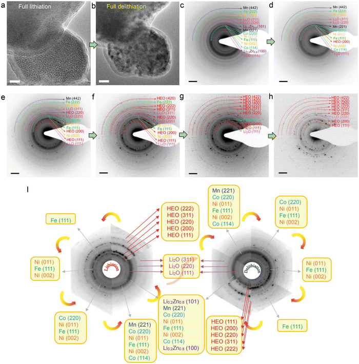 | ||
| Fig. 6 Structural reversibility of the HEO structure upon delithiation. (a) and (b) TEM morphology evolution of a fully delithiated HEO nanoparticle. (c)–(h) ED patterns from different delithiation stages. (i) Schematic diagram of the ED pattern evolutions during the first discharging/charging cycle. Copyright permission from Wiley, used from ref. 113. | ||
Spinel-type HEOs have been utilized as electrode materials for LIBs. This unique structure with three-dimensional Li+ transport pathways can potentially facilitate Li+ conductivity and thus improve lithiation kinetics. The two Wyckoff sites and rich oxygen vacancies are favorable for reversible Li+ storage. Ting et al. reported a surfactant-assisted hydrothermal method toward a spinel HEO (CrMnFeCoNi)3O4 anode for LIBs, which was found to have a desirable specific capacity of 1235 mA h g−1 and respectable capacity retention of 90% after 200 cycles.140 Most of the reported HEO anodes for LIBs contain Co which mainly contributes to high conductivity and reversible capacity. However, Co is expensive, and large quantities of global cobalt is mined in the Democratic Republic of the Congo, which suffers from political instability and ethical production methods (due to civil war, other violence, and child labour).153,154 Therefore, the development of Co-free HEO anodes is of great interest.
Chang et al. reported a Co-free spinel (CrMnFeNiCu)3O4 HEO and applied operando X-ray absorption spectroscopy (XAS) to study ion intercalation mechanisms.49 In comparison to conventional XAS that is operated in stepping mode, quick-scanning XAS with a monochromator oscillation frequency of 2 Hz has better signal-to-noise ratio sensitivity as well as superior time-resolution. Fig. 7 exhibits the various K-edge spectra for all the metallic elements in the HEO anode during the initial discharging-charging process. Upon Li+ uptake, the absorption edges of all the spectra shifted towards lower energy, suggesting that reduction happens during lithiation. After full lithiation at 0.01 V, operando spectra of all constituent elements are close to the plots of metal standards, indicating that the metallic Mn, Cu, Cr, Fe, and Ni formed at the end of lithiation process. At the delithiation stage, progressive shifts towards the positive side were observed in Mn, Cr, and Fe spectra, suggesting the occurrence of oxidation reactions. A minor shift was noticed in the Ni spectra. It is worthwhile to note that the absorption edge of Cu was almost unchanged throughout the delithiation, which is indicative of high irreversibility.
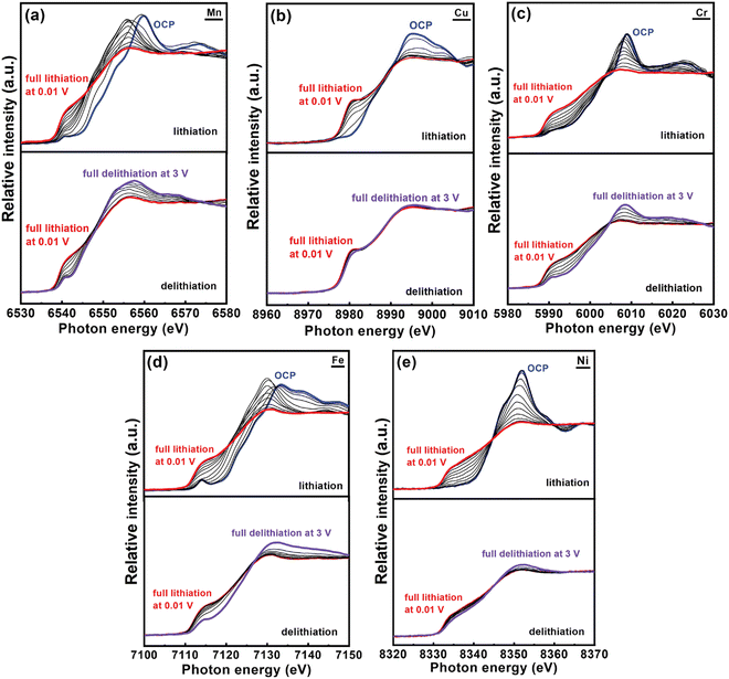 | ||
| Fig. 7 Operando XAS spectra of HEO anode obtained during first lithiation/delithiation process at 150 mA g−1 current density. The interval between spectra is 100 mA h g−1. Copyright permission from Wiley, used from ref. 49. | ||
Detailed coordination structure transformations of all the metallic elements present in HEO anodes were examined using first-derivative curves of the K-edge spectra. As shown in Fig. 8(a), the two peaks around 6539 and 6546 eV were ascribed to Mn0 in metallic Mn and Mn2+/3+ in HEO, respectively. After 250 mA h g−1, the Mn0 signal gradually becomes stronger while the Mn2+/3+ peak becomes weaker, suggesting that the conversion reaction between Mn2+/3+ and Mn0 occurs. Cu2+ undergoes a single-step conversion to form Cu0 (Fig. 8(b)). The Cu2+ characteristic peak located of 8983.9 eV is diminished up to lithiation of ≈250 mA h g−1 while the metallic Cu signal at 8979 eV became intensified. After this, the spectral features are almost unchanged. According to Fig. 8(c), two reduction reactions were observed during the charging and discharging processes; Cr3+ is reduced to Cr2+ before 0.44 V, then Cr2+ is reduced to metallic Cr0 from 675 and 1200 mA h g−1. Fe2+/3+ also displays two-step reduction with the reduction of Fe3+ to Fe2+ followed by reduction of Fe2+ to metallic Fe0 (Fig. 8(d)). Ni underwent a single-step conversion of Ni2+ to metallic Ni0 eventually (Fig. 8(e)). The redox behavior of the elements in the HEO anode is summarized in Fig. 8(f). At the beginning of the lithiation process, reduction reactions including Mn3+ → Mn2+ and Cu2+ → Cu0 are mainly responsible for the capacity contribution. The transitions Mn2+ → Mn0, Cr3+ → Cr2+, Fe3+ → Fe2+, Fe2+ → Fe0, and Ni2+ → Ni0 give rise to a charging potential plateau at around 0.5 V. The final Li+ storage charge-compensation was mainly resulted from Cr2+ → Cr0 conversion. As exhibited in Fig. 8(g), at the initial delithiation process, the measured capacity was largely originated from the oxidation reaction of metallic Mn. After ≈1.13 V, both Cr and Fe started to oxidize. The Cu reaction was almost invisible and provided the least capacity. The oxidation of Ni needed a large overpotential of ≈1.67 V, contributing to capacity only at the last stage.
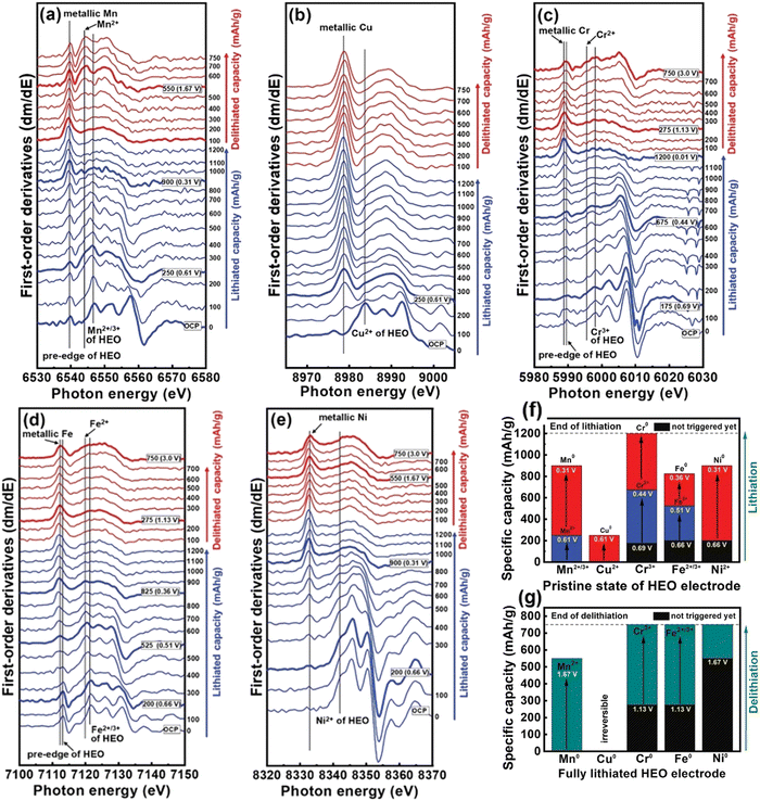 | ||
| Fig. 8 First-derivative plots of (a) Mn, (b) Cu, (c) Cr, (d) Fe, and (e) Ni XAS operando spectra in (CrMnFeNiCu)3O4 HEO anode during first lithiation and delithiation cycle at 150 mA g−1 current density. (f)–(g) Capacity contribution of all constituent elements in HEO electrode during first lithiation and delithiation cycle. Copyright permission from Wiley, used from ref. 49. | ||
HEO materials have also been reported as cathode materials for LIBs. Brezesinski et al. reported a high-entropy rock-salt-type fluoride oxide Li0.94(Co0.21Ni0.21Zn0.2Mg0.2Cu0.18)O1F0.87 and layered oxide LiNi0.2Mn0.2Co0.2Fe0.2Al0.2O2, which displays excellent Li+ storage capability.147 Ceder et al. applied the HE concept to the recently developed cation-disordered rocksalt (DRX) cathodes, which was found to be an effective method to suppress cation short-range order (SRO) due to the mixing of a larger number of TM species.146 The SRO reduction is favorable for Li+ storage capability. Three prototype compositions were designed with different numbers of TM species in order to assess their HE DRX strategy. Li1.3Mn0.4Ti0.3O1.7F0.3 was regarded as reference sample. Mn, Nb, Co, and Cr elements were successively incorporated into the former structure to form Li1.3Mn0.2Mn0.2Ti0.1Nb0.2O1.7F0.3 and Li1.3Mn0.1Co0.1Mn0.1Cr0.1Ti0.1Nb0.2O1.7F0.3. The three compositions were referred to as TM2, TM4, and TM6, respectively, based on the various number of TEM species present in each structure.
As shown in Fig. 9(a), 30% Li excess was included in all three compositions to facilitate Li intercalation without undermining the TM redox capacity. 15% fluorine was incorporated to substitute oxygen to ensure a good redox reservoir. Scanning electron microscopy (SEM) revealed that the particle size of TM6 samples is approximately 5–10 μm (Fig. 9(b)) and can be decreased to 200–500 nm by shaker milling with carbon during electrode fabrication. The refined XRD patterns of as-prepared samples are shown in Fig. 9(c). The lattice constants (a) of cubic TM2, TM4 and TM6 are 4.1918, 4.2286 and 4.2655 Å, respectively, indicating that lattice parameter increased with more TM species in the structure. The STEM-EDX elemental maps shown in Fig. 9(d) demonstrated that all the incorporated elements are uniformly distributed throughout the material.
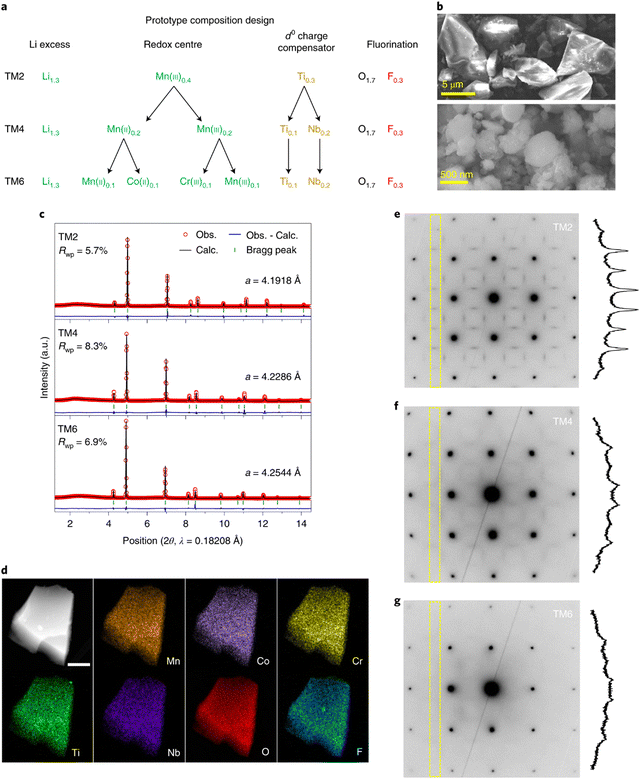 | ||
| Fig. 9 (a) Composition design of HEO cathodes with variations of TM ions, (b) SEM images of as-synthesized TM6, (c) synchrotron XRD patterns and refined lattice parameters of the as-prepared HEOs, (d) HAADF-STEM EDX mapping of elemental distribution in a particle cluster of TM6. Scale bar, 300 nm. (e)–(g) TEM ED patterns measured on TM2 (e), TM4 (f) and TM6 (g) along the [100] zone axis. Copyright permission from Nature materials, used from ref. 146. | ||
Electron diffraction patterns in the TEM was used to evaluate the cation short-range order (SRO, Fig. 9(e)–(g)). The diffraction spots can be indexed to cubic Fm![[3 with combining macron]](https://www.rsc.org/images/entities/char_0033_0304.gif) m rock salt structures. The strength of the SRO is qualitatively associated with the intensity of the diffuse scattering, which is integrated within the dashed rectangular areas. The results clearly show that the intensity of the diffuse scattering decreased with an increase in the number of TM species, indicating that higher entropy is advantageous to suppress SRO in the DRX structure.
m rock salt structures. The strength of the SRO is qualitatively associated with the intensity of the diffuse scattering, which is integrated within the dashed rectangular areas. The results clearly show that the intensity of the diffuse scattering decreased with an increase in the number of TM species, indicating that higher entropy is advantageous to suppress SRO in the DRX structure.
The electrochemical performance of the three electrodes was evaluated using galvanostatic cycling. Within a voltage window from 1.5 to 4.7 V, the TM2 electrode delivered a specific capacity of 220 mA h g−1, which increased to 220 mA h g−1 for TM4 and to 307 mA h g−1 for TM6. These rate capability results are shown in Fig. 10(a)–(f). The TM2 electrode initially delivers a specific capacity of 220 mA h g−1 at 20 mA g−1 current density, which rapidly decreases to 58 mA h g−1 at a higher current density of 2 A g−1 with a 74% capacity loss. With more TM ions in the DRX structure, the capacity loss at high current rate is reduced to 58% for TM4 and to 45% for TM6, respectively. The TM6 electrode still delivers a capacity of 170 mA h g−1 even at a high current density of 2 A g−1. The excellent electrochemical performance of TM6 electrode supports the authors’ design strategy of the application of the HE concept in the DRX electrode structure, which could potentially reduce SRO and thus improve the Li+ storage capability in these materials.
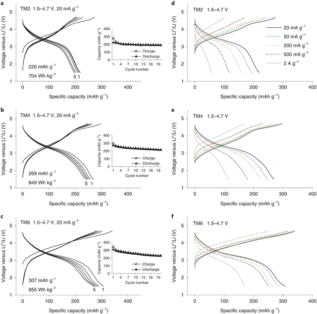 | ||
| Fig. 10 Voltage curves of TM2 (a), TM4 (b) and TM6 (c) within the potential scope of 1.5–4.7 V at 20 mA g−1 current density (insets show the capacity retention plots), rate performance of TM2 (d), TM4 (e) and TM6 (f) exhibiting the 1st voltage curves between 1.5 and 4.7 V at 20, 50, 200, 500 and 2000 mA g−1. Copyright permission from Nature materials, used from ref. 146. | ||
Except for HEOs, HE chalcogenides have also displayed great electrochemical performances when used as electrodes for LIBs. Recently, Breitung et al. utilized HE sulfides as the anode in LIBs.60 A one-step mechanochemical reaction was used to produce different HE sulfides including (FeMnNiCoCr)S2, (FeMnNiCoCu)S2, (FeMnNiTiCr)S2 and (FeMnNiCoCr)S. As shown in Fig. 11(a), the (FeMnNiCoCr)S2 electrode delivers the best electrochemical performance with a high reversible capacity of 716 mA h g−1 at a high current density of 2.5 A g−1. In addition, the (FeMnNiCoCr)S2 electrode exhibited excellent cycling capability (Fig. 11(b)) and long-term cycling performance (Fig. 11(c)).
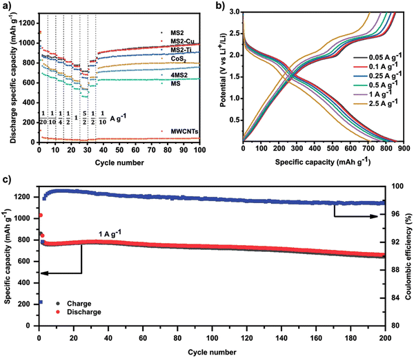 | ||
| Fig. 11 (a) Galvanostatic rate performance test of all HESs, CoS2, 4MS2, and MWCNTs half-cell at different current densities and 25 °C in the voltage range between 0.01 and 3 V vs. Li+/Li. (b) Voltage profiles of MS2 half-cell at different currents. (c) Specific charge/discharge capacity of MS2 half-cell and Coulombic efficiency as a function of cycle number at 1 C and 25 °C in the range between 0.01 and 3 V. Copyright permission from Wiley, used from ref. 60. | ||
HEMs for sodium-ion batteries (SIBs)
The layered transition metal (TM) oxide NaxTMO2 (x ≤ 1) is regarded as one of the most promising cathode materials for SIBs due to its high energy density, which can be structurally categorized into O3, P3 and P2 types (where P and O represents prismatic and octahedral crystal structures, respectively, and 2 or 3 represents the minimum number of transition metal layers in the repeating cell unit).155,156 However, irreversible structural changes during the Na+ intercalation process detrimentally affects the electrochemical performance, which is the primary cause of capacity fading.157 It has been reported that the introduction of single or multiple heterogenous metals into NaxTMO2 is an effective approach to stabilize the host structure and alleviate the cationic migration from the TM layers to the Na layers.103 This strategy can be extended to the design of HEMs containing multiple elements in a single-phased structure.103,158 A selection of previously-reported HEMs as electrode materials for SIBs are summarized in Table 2.| HEMs | Synthesis method | Structure | Electrochemical performance | Capacity retention | Ref. |
|---|---|---|---|---|---|
| a The Pechini method of synthesis is a modified sol–gel method which utilizes cation complexation with citric acid in a water–ethanol solution to form a homogenous mixture of precursors. The pH was adjusted to 5 and ethylene glycol was added and solution annealed at 120 °C for at least 12 hours to leave a porous gel and calcinated twice, once at 480 °C for 6 h and again at 850 °C for 12 h in air.170 | |||||
| NaxTi0.16Mn0.16Fe0.16Co0.16Ni0.16Cu0.17O2 | Sol–gel method | O3/P3 phase | 139 mA h g−1 at 0.1 C current density | ∼100% after 10 cycles | 159 |
| NaNi0.4−xCuxFe0.2Mn0.2Ti0.2O2 | Solid-state reaction | O3-type phase | 129 mA h g −1 at 24 mA g−1 current density | 74.83% after 50 cycles | 160 |
| Na0.7Mn0.4Ni0.3Cu0.1Fe0.1Ti0.1O1.95F0.1 | High-temperature sintering | P2/O3 phase | 134 mA h g−1 at 20 mA g−1 current density | 93.3% after 200 cycles | 161 |
| CoZnCuNiFeZrCeOx-PMA | Solvo-thermal method | Fluorite structure | 220 mA h g−1 at 300 mA g−1 current density | 92% after 5000 cycles | 162 |
| Na0.67Li0.16Fe0.16Co0.16Ni0.16Mn0.33O2 | Solid-state reaction | Superlattice structure | 171 mA h g−1 at 0.1 C current density | 89.3% after 300 cycles | 103 |
| Na(Fe0.2Co0.2Ni0.2Ti0.2Sn0.1Li0.1)O2 | Solid-state reaction | O3-type phase | 81 mA h g−1 at 2.0 C current density | 81% after 100 cycles | 163 |
| NaCu0.1Ni0.3Fe0.2Mn0.2Ti0.2O2 | Pechinia method | O3-type phase | 130 mA h g−1 at 0.1 C current density | 71% after 500 cycles | 164 |
| Na0.62Mn0.67Ni0.23Cu0.05Mg0.07Ti0.01O2 | Hydrothermal method | P2-type phase | 148 mA h g−1 at 12 mA g−1 current density | 75% after 2000 cycles | 165 |
| NaNi0.25Mg0.05Cu0.1Fe0.2Mn0.2Ti0.1Sn0.1O2 | High-temperature sintering | O3-type phase | 131 mA h g−1 at 14 mA g−1 current density | 75% after 500 cycles | 72 |
| NaMn0.2Fe0.2Co0.2Ni0.2Ti0.2O2 | High-temp-erature sintering | O3/P3 phase | 180 mA h g−1 at 0.1 C current density | 97% after 100 cycles | 166 |
| Na0.6(Ti0.2Mn0.2Co0.2Ni0.2Ru0.2)O2 | High-temp-erature sintering | P2 phase | 164 mA h g−1 at 0.1 C current density | 99.78% after 40 cycles | 167 |
| NaNi0.12Cu0.12Mg0.12Fe0.15Co0.15Mn0.1Ti0.1Sn0.1Sb0.04O2 | High-temp-erature sintering | O3-type phase | 110 mA h g−1 at 0.1 C current density | 83% after 500 cycles | 103 |
| Na3VAl0.2Cr0.2Fe0.2In0.2Ga0.2(PO4)3 | Sol–gel method | NASICON-structure | 102 mA h g−1 at 11 mA g−1 current density | 86.8% after 5000 cycles | 40 |
| Na3(Ti0.2V0.2Mn0.2Cr0.2Zr0.2)2(PO4)3 | Sol–gel method and solid-state reaction | NASICON-structure | 96.5 mA h g−1 at 100 mA g−1 current density | 36.3% after 100 cycles | 168 |
| Na3V1.9(Ca,Mg,Al,Cr,Mn)0.1(PO4)2F3 | Sol–gel method and solid-state reaction | NASICON-structure | 118 mA h g−1 at 0.1 C current density | 80.4% after 2000 cycles | 42 |
| Na1.41Mn0.32Fe0.11Co0.28Ni0.32Cu0.32[Fe(CN)6]·2.89H2O | Co-precipitation | Cubic structure | 92.6 mA h g−1 at 150 mA g−1 current density | 95% after 10![[thin space (1/6-em)]](https://www.rsc.org/images/entities/char_2009.gif) 000 cycles 000 cycles |
43 |
| Na1.70Fe0.2Mn0.2Co0.2Ni0.2Cu0.2[Fe(CN)6]0.98□0.02·2·35H2O (□ = [Fe(CN)6] vacancy) | Co-precipitation | Cubic structure | 115 mA h g−1 at 100 mA g−1 current density | 79.6% after 1000 cycles | 44 |
| Nax(FeMnNiCuCo)[Fe(CN)6] | Co-precipitation | Cubic structure | 120 mA h g−1 at 10 mA g−1 current density | ∼100% after 3000 cycles | 169 |
Tobola et al. utilized a combination of high-temperature solid-state and low-temperature sol–gel methods to produce an O3-type layered six-component HEO Na1Ti0.16Mn0.16Fe0.16Co0.16Ni0.16Cu0.16O2.159 It was found that the presence of copper is favorable for improvement of ion conductivity and structural stability. Cheng reported a P2/O3 biphasic Na0.7Mn0.4Ni0.3Cu0.1Fe0.1Ti0.1O1.95F0.1 with a remarkable initial coulombic efficiency (ICE), which is also able to deliver a respectable discharge capacity of 86.7 mA h g−1 at a current density of 0.8 A g−1 with a high ICE of 97.6%.161 Density functional theory (DFT) calculations revealed that the excellent electrochemical performance potentially originates from reversible structural evolution and fast Na+ diffusion kinetics.
Xin et al. reported the HEO O3-structure NaxTi0.16Mn0.16Fe0.16Co0.16Ni0.16Cu0.17O2.171 The XRD pattern (Fig. 12(a)) shows that this material is comprised of a pure O3 phase. Two characteristic peaks at 2θ ≈ 18.5° and 44.1° suggested that a honeycomb-type superlattice phase is formed due to the ordering between Li ions and TM ions caused by a large difference in ionic radii. A uniform plate-like morphology was observed in SEM imaging (Fig. 12(c)). As shown in Fig. 12(d) and (e), HAADF-STEM imaging further confirmed the O3 atomic structure. The SAED pattern projected along the [001] zone axis also revealed the diffraction pattern of a layered O3 phase (Fig. 12(f)). Some diffraction spots with relatively weaker contrast around the bright spots can be noticed from the perspective of the [010] zone axis, which is in accordance with superlattice formation (Fig. 12(g)). EDX spectroscopic mapping shows that there is uniform elemental distribution throughout the particles at the nanoscale (Fig. 12(h)).
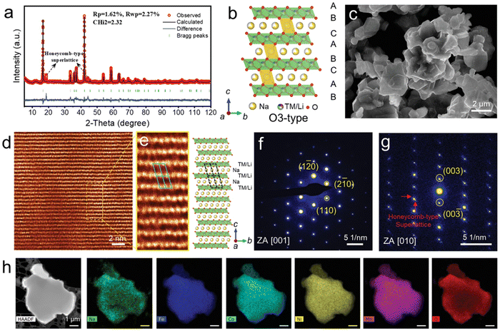 | ||
| Fig. 12 Structure characterization of pristine NaLFCNM materials. (a) Rietveld refinement of X-ray diffraction (XRD) pattern. (b) Schematic O3-type crystal structure with the presence of superlattice phase. (c) SEM image. (d) HAADF-STEM image of the [001] zone axis. (e) HAADF-STEM image (left) of the area selected from (d) and the corresponding structure model (right). (f) and (g) SAED patterns projected from the zone axis of (f) [001] and (g) [010] zone axis. (h) STEM-EDX spectroscopic mapping. Copyright permission from Wiley, used from ref. 171. | ||
The charge/discharge curves in Fig. 13(a) show that NaLFCNM cathode delivers considerable capacity retention capability with a slight voltage fading when cycling between 2.0–4.5 V at 0.3 C current density. Long-term cycling performances at higher density are exhibited in Fig. 13(b) and (c), which both delivers excellent cycling capability. The rate performance is very respectable, as shown in Fig. 13(d); even at a high current density of 10 C, a desirable discharge capacity of 78.2 mA h g−1 is still achieved, which accounts for 45.3% to the discharge capacity of 0.1 C. This rate capability is potentially facilitated by fast Na+ diffusion kinetics of about ca. 10−11 cm2 S−19 obtained from galvanostatic intermittent titration technique (GITT) measurements (Fig. 13(e)).
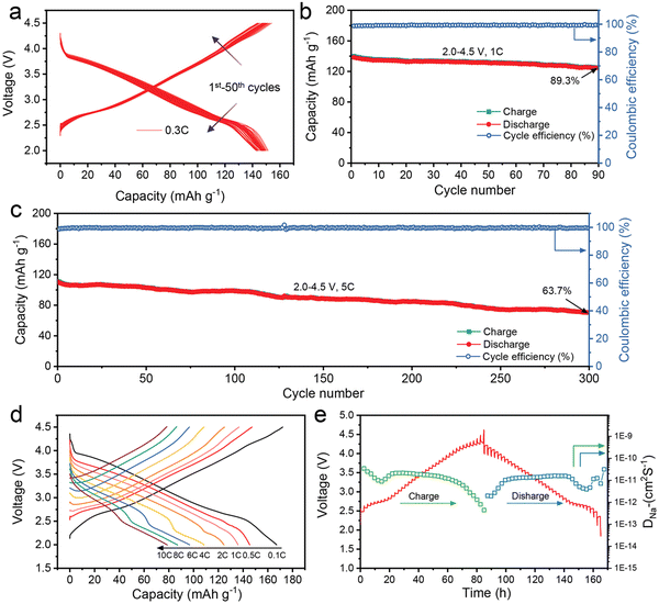 | ||
| Fig. 13 Electrochemical performance of the NaLFCNM cathode. (a) The charge–discharge profiles at a 0.3 C rate for 50 cycles. (b) and (c) Long-term cycling performance at (b) 1 C rate and (c) at 5 C rate. (d) Charge–discharge curves at different cycling rates. (e) GITT curves for the charge and discharge states of the first cycle and corresponding DNa+. Copyright permission from Wiley, used from ref. 171. | ||
The structural evolution during the sodium intercalation process was investigated by in situ synchrotron XRD experiments. As shown in Fig. 14(a), when charging from open-circuit voltage (OCV) to 3 V during the first cycle, the original O3 phase gradually vanished, and a P3-type structure is observed. At the end of charge (cut-off voltage: 4.5 V), co-existence of the P3/O3 biphasic system can be observed, which was confirmed by the P3 + O3 lattice sequence in the HRTEM image (Fig. 14(d)). Upon the subsequent Na+ deintercalation process, the P3-type phase is retained until discharging to around 2.6 V. The P3 phase gradually recovers back to O3 phase around 2.0 V, which was also verified by the HRTEM image (Fig. 14(e)). The lattice parameters at different Na+ (de)intercalation stages which were obtained from the in situ XRD patterns are shown in Fig. 14(c), which shows that the deviation of a and c parameters during initial cycling is 1.84% and 1.97%, respectively. This small volume change of NaLFCNM indicates a minor structural change during the Na+ intercalation process and is responsible for the excellent cycling performance. Fig. 14(f) schematically illustrates the structural evolution during initial charge/discharge process.
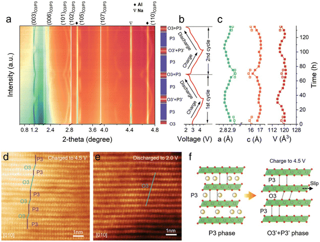 | ||
| Fig. 14 (a) In situ high-energy XRD patterns (λ = 0.15416 nm with a Cu Kα radiation source) of NaLFCNM during the first charge–discharge cycle. (b) Corresponding voltage profile during the ex situ XRD experiment. (c) Calculated lattice parameters (a-axis, c-axis, and unit cell volume [V]) of NaLFCNM at different charge/discharge states. Ex situ HR-TEM image of NaLFCNM at (d) 4.5 V state and (e) 2 V state. (f) Schematic illustrations of the whole phase evolution of NaLFCNM upon charge and discharge. Copyright permission from Wiley, used from ref. 171. | ||
Sodium super ionic conductor (NASICON) materials have the advantages of 3D ion transport channels, impressive structural robustness and a large number of Na+ vacancies, which can significantly alleviate the structural evolution of repeating Na+-insertion/-extraction processes and facilitate Na+ diffusion kinetics, enabling them to be competitive as SIBs172–174 Zhao et al. designed the high-entropy NASICON-type material Na3VAl0.2Cr0.2Fe0.2In0.2 Ga0.2(PO4)3 as a SIB cathode.40 It was found that the reversible redox reaction of V4+/V5+ could be realized and the irreversible phasic transformation above 4.0 V vs. Na+/Na could be effectively depressed. A high energy density of 444 W h kg−1 was achieved, which outperformed Na3VAl(PO4)3 and Na3VCr(PO4)3.
Na3(VO1−xPO4)2F1+2x (0 ≤ x ≤ 1) is of great interest due to its high specific capacity.175 The electrochemical performance can be tailored by adjusting the F/O ratio.176 Wu et al. reported the high-entropy phosphate cathode Na3V1.9(Ca,Mg,Al,Cr,Mn)0.1(PO4)2F3 (HE-NVPF).42 Electrochemical tests showed that HE-NVPE delivers remarkably improved energy density, cycling performance and rate capability compared to pristine NVPF (P-NVPF) and other fluorophosphate counterparts.
As shown in Fig. 15(a), three pairs of redox peaks (A1/C1, A2/C2, and A3/C3) in the CV curve can be identified in p-NVPF cathode, while the A1/C1 peaks at low-voltage region disappeared for HE-NVPF cathode, which is in accordance with the corresponding GCD plots in Fig. 15(b). More importantly, the two couples of redox peaks in the CV curves in HE-NVPF are sharper and larger than that of p-NVPF electrode. As shown in Fig. 15(c), the capacity contribution above 3.7 V working voltage for HE-NVPF accounts for 45.7%, which is much higher than the 38.3% for p-NVPF. Indeed, the absence of a 3.4 V plateau region for HE-NVPF cathode improves the working voltage and thus achieves a higher specific capacity, further delivering higher energy density. The HE-NVPF cathode electrode also delivers improved rate performance (Fig. 15(d) and (e)), and the specific capacity for HE-NVPF at different current densities ranging from 0.1 C to 50 C is higher than that of the p-NVPF electrode. Ragone plots (Fig. 15(f)) show that the HE-NVPF displays significant improvement both in energy density and power density in comparison to p-NVPF. In addition, the long-term cycling performance test in Fig. 15(g) and (h) suggests that the capacity ratio of HE-NVPF electrode is significantly higher than p-NVPF, which achieves 90.2% and 80.4% at 0.5 C and 20 C, respectively, after 400 cycles.
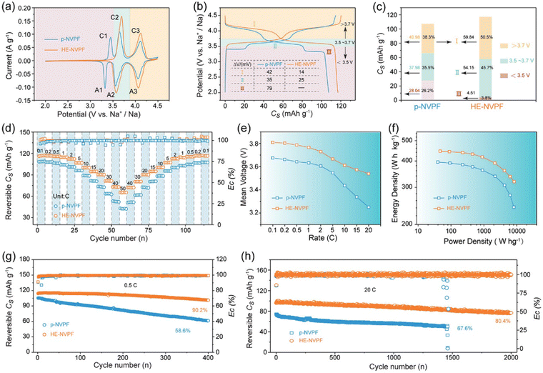 | ||
| Fig. 15 Electrochemical properties of HE-NVPF and p-NVPF tested in coin-type half-cells. (a) CV patterns at a scan rate of 0.1 mV s−1. (b) GCD curves at 0.1 C in the potential windows of 2.0–4.3 V versus Na+/Na. (c) Discharge Cs values and capacity contribution rates of discharge voltage intervals calculated from the discharge curves in (b). (d) Rate capability. (e) Vm variations calculated based on the discharge curves along with rates. (f) Ragone plots. (g) and (h) Cycling performance at 0.5 and 20 C. Copyright permission from Wiley, used from ref. 42. | ||
Prussian blue analogues (PBAs) are transition metal hexacyanoferrates with a stable open channel structure, ion diffusion paths and redox-active sites.177 These intrinsic properties make them a competitive cathode material for SIBs, usually having high reversible capacity, excellent rate performance and high working voltage.178,179 The general chemical formula of PBAs can be represented as AxM[Fe(CN)6]y□m·nH2O (with 0 < x ≤ 2, 0 < y ≤ 1, y + m = 1), where A is an alkali metal ion, M and □ represent transition-metal ions and [Fe(CN)6] vacancies, respectively.180 Brezesinski et al. applied the high-entropy approach to the PB structure Nax(FeMnNiCuCo)[Fe(CN)6] (simplified as HE-PBA), where five different transition metals are occupied in the M site in equimolar proportions.181
The crystal structure of HE-PBA is schematically illustrated in Fig. 16(a), where Fe, Mn, Ni, Cu, and Co share the nitrogen-coordinated M site. The configurational entropy value of HE-PBA is calculated to be 1.61R based on the eqn (1), which is higher than medium-entropy PBA (ME-PBAs) with a value of 1.39R. The X-ray diffraction pattern and corresponding Rietveld refinement profile is shown in Fig. 16(c), which reveals a single-phase cubic structure in the Fm![[3 with combining macron]](https://www.rsc.org/images/entities/char_0033_0304.gif) m space group. Fourier transforms of EXAFS data in Fig. 16(d) show that the radial distribution of all the TM metals is similar, indicating a homogeneous distribution of the cations. The three characteristic peaks are attributed to the M–N/C, M–C/N and M–Fe shells.
m space group. Fourier transforms of EXAFS data in Fig. 16(d) show that the radial distribution of all the TM metals is similar, indicating a homogeneous distribution of the cations. The three characteristic peaks are attributed to the M–N/C, M–C/N and M–Fe shells.
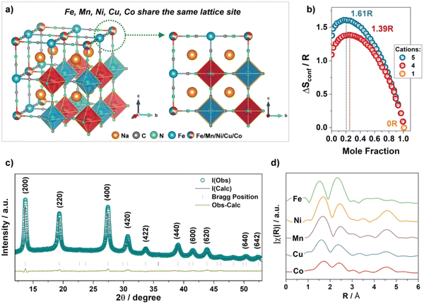 | ||
| Fig. 16 (a) Schematic illustration of the crystal structure of HE-PBA. (b) Dependence of configurational entropy on the number of elements. (c) XRD pattern of HE-PBA and Rietveld refinement. (d) Fourier transform of the EXAFS signals collected from the HE-PBA material, for each metal edge, plotted with a y-axis offset for better clarity. Copyright permission from Wiley, used from ref. 181. | ||
As shown in Fig. 17(a), HE-PBA electrode delivers an initial-cycle discharge capacity of ca. 100 mA h g−1 at 0.1 A g−1 current density, which is higher than those ME-PBAs where one of the TM metal cations is removed. In addition, the cycling performance of the HE-PBA electrode shows that it retains around 87 mA h g−1 after 150 cycles. All electrodes show similar characteristic redox plateaus at around 3.45 and 3.22 V for charge and discharge, respectively, which is consistent with the redox peaks from the CV curves in Fig. 17(c). The HE-PBA electrode displays highest specific capacities at various current densities ranging from 0.2 to 1.0 A g−1.
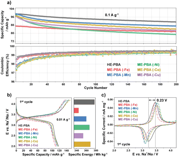 | ||
| Fig. 17 (a) Galvanostatic cycling at 0.1 A g−1 of electrodes based on HE-PBA (in black), ME-PBA(-Fe) (in red), ME-PBA(-Mn) (in blue), ME-PBA(-Ni) (in green), ME-PBA(-Co) (in dark yellow), or ME-PBA(-Cu) (in purple). Specific discharge capacities (top) and Coulombic efficiencies versus the cycle number (bottom) are shown (1st cycle is omitted for clarity). (b) First-cycle voltage profiles at 0.01 A g−1 (left) and comparison of specific energies (right). (c) Initial cyclic voltammogram at 0.05 mV s−1 for HE-PBA and the different ME-PBAs. Copyright permission from Wiley, used from ref. 181. | ||
Operando XRD data collected during two cycles of the HE-PBA electrode against Na+/Na were performed to reveal the correlation between structure and electrochemical performance. At a low current density of 3.5 mA g−1, the (200), (220) and (400) characteristic reflections undergo continuous but minor shifts to higher 2θ angles, which is accompanied by minor broadening of the peaks (Fig. 18(a)). Fig. 18(b) shows that the (200) peak intensifies at the end of first charging process. In the subsequent discharge cycle, the three reflections gradually shift back to their pristine positions. Similar behavior is observed in the second cycle, suggesting some reversibility in the structural changes observed. There is no other phase observed during the whole measurement, which indicates that the sodium intercalation chemistry in HE-PBA occurs via a solid-solution mechanism. Compared to the phase-transition mechanism, the solid-solution mechanism can maintain electrode structure during the Na+ intercalation process, yielding superior cycling performance.182 The cubic lattice parameters are summarized in Fig. 18(c); the values remain almost unchanged during the two cycles, indicating that the HE-PBA electrode has negligible structural strain upon de/intercalation processes, which agrees with its respectable cycling performance.
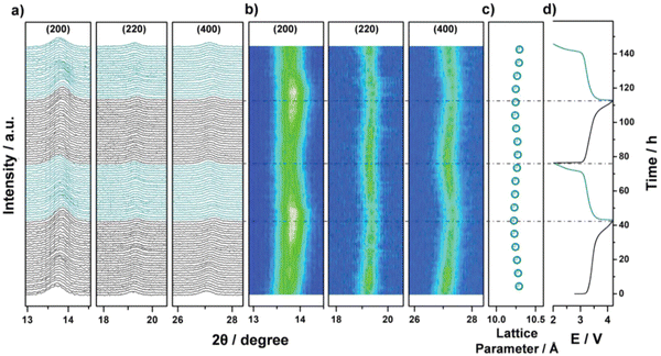 | ||
| Fig. 18 Operando XRD analysis of the electrochemical extraction/insertion of Na ions from/into HE-PBA. (a) Waterfall diagrams, (b) contour plots of consecutively recorded patterns, (c) lattice parameter changes, and (d) the corresponding dis/charge curves for the first two cycles. Copyright permission from Wiley, used from ref. 181. | ||
HEMs for lithium–sulfur batteries
Lithium–sulfur (Li–S) batteries have high theoretical specific capacities of 1675 mA h g−1.183 However, sulfur redox reactions often lead to the uncontrollable shuttling of liquid-state lithium polysulfides (LiPSs), resulting in the rapid loss of active material and dramatic capacity fading. A common engineering solution is to utilize metal oxides as additives for the entrapment of LiPSs as they often show excellent adsorption capability owing to the chemical bonding between metal oxides and LiPSs.184,185 Recently, HE metal oxides have been applied as additives in Li–S batteries due to their vast compositional space and abundant combinatorial active sites, which can potentially provide robust chemical confinement of LiPSs with fast kinetics for polysulfide conversion.15,186,187 Chen et al. utilized a self-sacrificing multi metal–organic framework (M-MOFs) to prepare a HEO (Ni0.2Co0.2Cu0.2Mg0.2Zn0.2)O.188 When employed as a cathode additive for Li–S batteries, it provides varieties of randomly distributed active metal sites with good electronic conductivity for anchoring polysulfides. A high specific capacity of 1244 mA h g−1 was observed, with a capacity retention of 63% after 800 cycles at 0.5 C current density. Gao et al. adopted an electrospinning-calcination process to prepare high-entropy perovskite oxide nanofibers of the type La(Cr0.2Mn0.2Fe0.2Co0.2Ni0.2)O3 (HE-LMO) and La0.8Sr0.2(Cr0.2Mn0.2Fe0.2Co0.2Ni0.2)O3 (HE-LSMO).189 The as-prepared HEO nanofibers, which have a unique porous structure, could provide rich exposure sites with sulfur. In comparison to LaMnO3 and HE-LMO samples, HE-LSMO plays a bidirectional catalytic role in promoting both the reduction of soluble LiPS and the re-oxidation of insoluble Li2S. Therefore, it enables fast reaction kinetics for the liquid–solid conversion process. This novel S/HE-LSMO cathode has been reported with a high sulfur loading of 8.4 mg cm−2 and a respectable cycling capability at 0.1 C rate.HEMs for Zn-ion batteries (ZIBs)
Divalent Zn-ion batteries (ZIBs) are of great interest due to their high volumetric energy density.190 Nevertheless, poor structural stability, slow ion diffusion kinetics, low working voltage, and undesirable energy/power density of cathode electrodes currently hinder the practical application of ZIBs.191 The development of advanced cathode materials with advantageous properties is key for the optimization of ZIBs. Jin et al. reported a high-entropy Prussian blue analogues (HE-PBA) K(MnCuFeNiCo)[Fe(CN)6] for Zn air batteries using a citrate-assisted controlled crystallization method at room temperature.192The HE-PBA delivers best electrochemical performance compared to its low-entropy counterparts. As shown in Fig. 19(a), the HE-PBA electrode attains a high initial discharge capacity of 90 mA h g−1 and excellent capacity retention of 82% after 100 cycles. The rate performance was also studied with the HE-PBA electrode delivering average capacities of 89, 80, 69, 51, 53 and 45 mA h g−1 at 0.1, 0.2, 0.3, 0.5, 1 and 2 A g−1 current densities, respectively. Nyquist plots of as-prepared electrodes consist of two regions: a semicircle and a straight line, which is related to the charge transfer and electron diffusion process, respectively. It is notable that HE-PBA electrode delivers smallest Rct value compared to other electrodes. In addition, the galvanostatic intermittent titration technique (GITT) was performed to acquire Zn2+ diffusion kinetics during charging/discharging processes, as shown in Fig. 19(d), the HE-PBA electrode delivers a higher Zn2+ diffusion coefficient of about 10−9–10−10 cm2 S−1 compared with the KMnHCF electrode. These results show that high-entropy effect may give rise to better charge transfer kinetics in ZIBs.
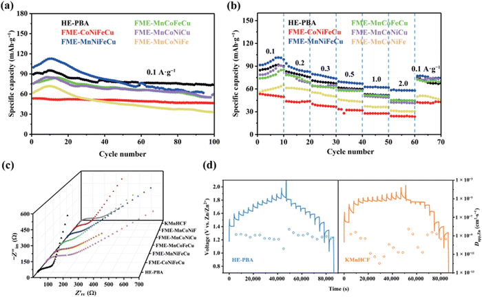 | ||
| Fig. 19 Electrochemical performance of HE-PBA as ZIB: (a) cycling capability at 0.1 A g−1, (b) rate performance, (c) Nyquist plots of different electrodes, (d) GITT curves and corresponding Zn2+ diffusion coefficients of HE-PBA and KMnHCF during charge/discharge process, respectively. Copyright permission from Nano research, used from ref. 192. | ||
Rosen et al. prepared a HE MXene of formula Ti1.1V0.7CrxNb1.0Ta0.6C3Tz by selective etching of a HE MAX phase.193 SEM, XRD, and EDX spectroscopic mapping reveal that a layered structure of the freestanding HE MXene film is obtained and elements are homogeneously distributed throughout the material. The HE MXene films were tested as zinc ion hybrid supercapacitors (ZHSCs), and achieved capacities of 77 and 43 mA h g−1 at current densities in the range 0.5–10 A g−1 respectively, with a respectable capacity retention of ca. 90% after 10![[thin space (1/6-em)]](https://www.rsc.org/images/entities/char_2009.gif) 000 cycles. This excellent performance is achieved using both Zn(CF3SO3)2 and the more cost-effective ZnCl2 as electrolyte. The HE MXene films also achieved capacities of 126 and 48 mA h g−1 when applied as a Li-ion cathode, at current densities of 0.01 and 2.0 A g−1, respectively. This study demonstrates that HE MXene material is another promising candidate for energy storage devices.
000 cycles. This excellent performance is achieved using both Zn(CF3SO3)2 and the more cost-effective ZnCl2 as electrolyte. The HE MXene films also achieved capacities of 126 and 48 mA h g−1 when applied as a Li-ion cathode, at current densities of 0.01 and 2.0 A g−1, respectively. This study demonstrates that HE MXene material is another promising candidate for energy storage devices.
HEMs for supercapacitors
Recently, high entropy alloys have been explored as electrode materials for supercapacitors.100 Liqing et al. reported an approach for uniformly depositing HEA-NPs on aligned carbon nanofibers (CNFs) and employed them as electrode materials for supercapacitors.194 The introduction of CNFs enables high electron transport efficiency, which facilitates the formation of HEA-NPs. The FeNiCoMnMg/CNFs hybrid electrode delivers a high capacitance of 203 F g−1 and a specific energy density of 21.7 W h Kg−1. In another report, Shen et al. incorporated a thin layer of metal oxide (MO) on the outer surface of the HEA FeNiCoCuSn and then deposited this material on hypercrosslinked polymer-based carbon (HCPC).195 The HEA-NP/HCPCs/MO nanocomposite displayed a high specific capacitance of 495.4 F g−1 in 1 M KOH and an excellent capacity retention of 94.7% after 15![[thin space (1/6-em)]](https://www.rsc.org/images/entities/char_2009.gif) 000 cycles.
000 cycles.
Jiang et al. prepared a series of high-entropy Prussian blue analogues (HE-PBAs) (K(MgMnFeNiCu)Fe(CN)6, K(MgMnCoNiCu)Fe(CN)6, K(MnFeCoNiCu)Fe(CN)6, K(MgMnFeCoNi)Fe(CN)6, and K(MgMnFeCoCu)Fe(CN)6.196 The K(MgMnFeNiCu)Fe(CN)6 electrode displayed the best electrochemical activity, delivering the highest specific capacitance compared to the other HEAs at the same rate. The intrinsic 3D diffusion channels are favorable in electrochemical energy storage devices. Sundra et al. synthesized an HEO NP nanocomposite on the surface of carbon nanotubes (HEO-CNT) via sol–gel auto-combustion.102 This composite structure exhibited a high surface area of about 151 m2 g−1, which is beneficial for electron transport. A HEO-CNT-based full-cell was also assembled, which attains a specific capacity of 286 F g−1 at a scan rate of 10 mV s−1. The full-cell also displayed an energy density of 217 W h Kg−1 and power density of 24![[thin space (1/6-em)]](https://www.rsc.org/images/entities/char_2009.gif) 521 W kg−1.
521 W kg−1.
HEMs for fuel cells
HEMs have also exhibited potential as electrocatalytic electrode materials for fuel cells. Wei et al. prepared a HEA-based electrocatalyst PtPdAuNiCo/C for the ethylene glycol oxidation reaction (EGOR) in direct ethylene glycol fuel cells (DEGFC).197 Testing with cyclic voltammetry (CV), Chronoamperometry (CA), and CO stripping showed that the HEA delivered a lowered EGOR peak potential of 0.55 V, 20 mV lower than a Pt/C electrode with an EGOR activity of 0.482 A mg−1. As the DEGFC anode catalyst, it achieved a power density of 8.38 mW cm−2 which was 1.4× that of Pt/C. Xiaofeng et al. adopted a sol–gel method to prepare a library of LaMnO3-based high-entropy perovskite oxides (HEPOs) as enhanced cathode materials for solid oxide fuel cells (SOFCs).111 The optimum electrode (La0.2Nd0.2Sm0.2Ca0.2Sr0.2)MnO3 displays increased tolerance to A site cation size differences where higher thermochemical stability and good conductivity can be maintained at high temperatures (215.8 S cm−1 at about 970 °C).Zhao et al. applied A2BO4 high-entropy oxides to solar oxide fuel cells (SOFCs).198 The XRD pattern presented showed that the (La0.2Pr0.2Nd0.2Sm0.2Gd0.2)2CuO4 (HE-LCO) had a single tetragonal phase structure with space group I4/mmm. The HE-LCO delivered respectable conductivity of 64.5 S cm−1 at 800 °C with a thermal expansion coefficient of 12.19 × 10⁻⁶ K−1. The HE-LCO electrode also showed respectable catalytic activity in the oxygen reduction reaction (ORR) with a stable area-specific resistance of 0.52 Ω cm2 after 70 h in operation. The peak power density of the anode supported fuel cell attained 528 mW cm−2 at 700 °C; HE-LCO is thus a fairly promising candidate as a material for SOFC cathodes.
Zhou et al. adopted an impregnation method to prepare a nanostructured spinel high-entropy oxide (Fe0.2Mn0.2Co0.2Ni0.2Zn0.2)3O4 (FMCNZ). FMCNZ nanoparticles were uniformly distributed and infiltrated into a network on a Gd0.1Ce0.9O1.95 (GDC) skeleton.199 This novel heterostructured material delivered excellent performance when applied as a cathode material in SOFCs, reaching a maximum power density of 1080 mW cm−2 at 800 °C and respectable stability over 100 h operation at 750 °C. This work provides a potential method for designing high-performance SOFCs cathodes by combining the high-entropy concept with nanostructured materials.
Summary and outlook
HEMs have been increasingly explored as active materials in electrochemical energy storage devices. They generally exhibit superior electrochemical performance compared to binary and ternary systems which has been ascribed in part to effects arising from their high configurational entropy. Among them, HE oxides are the most promising electrode materials for energy storage devices. Many HE oxides with rock-salt, spinel, and perovskite structures undergo lithiation, a key feature of modern energy storage materials, and have been found, in general, to possess the dual advantages of high theoretical capacity and excellent reversibility during intercalation processes, which makes them candidates for electrochemical Li storage. In contrast, layered P2, O3 and hybrid P2/O3 HE oxides are primarily applied as cathode materials for electrochemical sodium ion storage. The P2 structure is featured in high ionic conductivity materials while O3 phase generally displays higher initial capacities. HE sodium super ionic conductor (NASICON) and Prussian blue analogue (PBA) materials have also been explored as cathodes for sodium ion batteries. NASICONs possess 3D ion transport channels together with numerous Na+ vacancies, and thus exhibit rapid Na+ diffusion kinetics. Due to their rigid open framework, PBAs have the advantages of high operating voltage, excellent rate capability and high specific capacity. In lithium–sulfur batteries, HE oxide additives exhibit superior performance by avoiding the formation of liquid-state lithium polysulfides and thus capacity fading is stymied. For surface charge storage in supercapacitors, HE alloys, and HE oxides deliver high storage capacity and exceptional cyclic stability.Although significant advancements have been made in HEM-based electrochemical energy storage devices, there are still challenges remaining. These revolve around issues such as understanding phase transformation during synthetic processes, better in-depth understanding of the charge storage mechanisms, and optimal design of the composition and morphology of materials (and also interlayer distances for layered HEMs). A significant challenge remains on the synthesis of HEMs. Atom-up approaches are required in order to obtain maximum mixing of multiple elements into a single phased lattice.200 It should also be noted again that most synthetic techniques require high temperatures and long timescales in current synthetic procedures, something that may currently stymie production in future especially in the move to sustainable industrial processes. Ex situ materials characterization is one method of obtaining further understanding of HEM synthesis on varying timescales. For example, the evolution of colloidal NiPdPtRhIr HE nanoparticles was investigated on the minute timescale and it was found that initial Pd-rich PdNi seeds were formed, followed by the autocatalytic integration of the further metals, eventually yielding roughly equimolar nanoparticles.201–203 The use of in situ/operando characterization methods would also greatly enhance our understanding of HEM formation.
The structure–composition–property correlation in HEMs is another possible area that could yield significant benefit in both energy storage capacity, but also in device stability. The individual elements play a critical role in regulating the structure and performance, but it is not yet understood to a high degree how the interactions of different elements in the local environment effect performance. Theoretical calculations on substitutions of individual Mo atoms in 2H MoS2 slabs with Cr, Mn, W and Re atoms has recently shown a significant benefit towards lowering the absorption energy of protons for hydrogen evolution electrocatalysis, explaining the significantly improved HER performance of HE 2H-(CrMnMoWRe)S2 over the parent 2H-MoS2.20 This calculation substituted up to 3 individual Mo atoms in the slabs, but ideal HEMs are completely randomly distributed and equimolar. The distance of influence was also not understood from this provisional analysis, and is another possibility for future research. Most reported HEMs for energy storage systems emphasize the number of incorporated elements but fail to systematically investigate how the composition of each element influences the structure details and related properties.
The existence of various active sites on the HEMs surfaces is also a significant challenge towards gaining a comprehensive understanding of mechanistic information in energy storage. In situ XANES and TEM techniques are powerful tools to investigate the electronic states and structural transformation during charging/discharging process, which is vital for complicated storage mechanism of HEMs; given the structural complexity of many HE materials, these are likely to generate rather complex data that may not even be representative of the whole sample, requiring other complementary and multiscale techniques to fully comprehend. A final advancement in HEMs for energy storage is expanding the scope of investigated HEMs. HE oxides are the most common material utilized to date, but there remains limited investigations into HE chalcogenides, MXenes, oxyfluorides, borides, carbides, nitrides, and phosphides, to name but a few.
Conflicts of interest
There are no conflicts of interest to declare.Acknowledgements
J. Q. Acknowledges funding from Chinese Scholarship Council (CSC) 201906240222. M. A. B and D. J. L. acknowledge support from UK Research and Innovation via the Engineering and Physical Sciences Research Council (EP/W033348/1).References
- D. Larcher and J. M. Tarascon, Nat. Chem., 2015, 7, 19–29 CrossRef CAS PubMed
.
- J. Chow, R. J. Kopp and P. R. Portney, Science, 2003, 302, 1528–1531 CrossRef PubMed
.
- S. Chu, Y. Cui and N. Liu, Nat. Mater., 2017, 16, 16–22 CrossRef PubMed
.
- C. Chen, Q. Liang, G. Wang, D. Liu and X. Xiong, Adv. Funct. Mater., 2022, 32, 2107249 CrossRef CAS
.
- D.-c Zuo, S.-c Song, C.-s An, L.-b Tang, Z.-j He and J.-c Zheng, Nano Energy, 2019, 62, 401–409 CrossRef CAS
.
- S.-q Yang, P.-b Wang, H.-x Wei, L.-b Tang, X.-h Zhang, Z.-j He, Y.-j Li, H. Tong and J.-c Zheng, Nano Energy, 2019, 63, 103889 CrossRef CAS
.
- Z. Jiang, Y. Li, C. Han, Z. Huang, X. Wu, Z. He, W. Meng, L. Dai and L. Wang, J. Electrochem. Soc., 2020, 167, 020550 CrossRef CAS
.
- J. Qu, T. Sheng, Z.-G. Wu, T.-R. Chen, H. Chen, Z.-G. Yang, X.-D. Guo, J.-T. Li, B.-H. Zhong and X.-S. Dou, J. Mater. Chem. A, 2018, 6, 13934–13942 RSC
.
- J. Qu, X.-X. Dai, J.-S. Cui, R.-X. Chen, X. Wang, Y.-H. Lin, R. Verduzco and H.-L. Wang, J. Mater. Chem. A, 2021, 9, 16554–16564 RSC
.
- J. W. Yeh, S. K. Chen, S. J. Lin, J. Y. Gan, T. S. Chin, T. T. Shun, C. H. Tsau and S. Y. Chang, Adv. Eng. Mater., 2004, 6, 299–303 CrossRef CAS
.
- B. Cantor, I. T. H. Chang, P. Knight and A. J. B. Vincent, Mater. Sci. Eng., A, 2004, 375–377, 213–218 CrossRef
.
- J.-W. Yeh, JOM, 2013, 65, 1759–1771 CrossRef CAS
.
- C. M. Rost, E. Sachet, T. Borman, A. Moballegh, E. C. Dickey, D. Hou, J. L. Jones, S. Curtarolo and J.-P. Maria, Nat. Commun., 2015, 6, 8485 CrossRef CAS PubMed
.
- A. Sarkar, L. Velasco, D. Wang, Q. Wang, G. Talasila, L. de Biasi, C. Kübel, T. Brezesinski, S. S. Bhattacharya, H. Hahn and B. Breitung, Nat. Commun., 2018, 9, 3400 CrossRef PubMed
.
- A. Sarkar, Q. Wang, A. Schiele, M. R. Chellali, S. S. Bhattacharya, D. Wang, T. Brezesinski, H. Hahn, L. Velasco and B. Breitung, Adv. Mater., 2019, 31, 1806236 CrossRef PubMed
.
- J. Dąbrowa, M. Stygar, A. Mikuła, A. Knapik, K. Mroczka, W. Tejchman, M. Danielewski and M. Martin, Mater. Lett., 2018, 216, 32–36 CrossRef
.
- M. Stygar, J. Dąbrowa, M. Moździerz, M. Zajusz, W. Skubida, K. Mroczka, K. Berent, K. Świerczek and M. Danielewski, J. Eur. Ceram. Soc., 2020, 40, 1644–1650 CrossRef CAS
.
- R.-Z. Zhang, F. Gucci, H. Zhu, K. Chen and M. J. Reece, Inorg. Chem., 2018, 57, 13027–13033 CrossRef CAS PubMed
.
- T. X. Nguyen, Y.-H. Su, C.-C. Lin and J.-M. Ting, Adv. Funct. Mater., 2021, 31, 2106229 CrossRef CAS
.
- J. Qu, A. Elgendy, R. Cai, M. A. Buckingham, A. A. Papaderakis, H. de Latour, K. Hazeldine, G. F. S. Whitehead, F. Alam, C. T. Smith, D. J. Binks, A. Walton, J. M. Skelton, R. A. W. Dryfe, S. J. Haigh and D. J. Lewis, Adv. Sci., 2023, 10, 2204488 CrossRef CAS PubMed
.
- M. Qin, J. Gild, H. Wang, T. Harrington, K. S. Vecchio and J. Luo, J. Eur. Ceram. Soc., 2020, 40, 4348–4353 CrossRef CAS
.
- M. Qin, Q. Yan, H. Wang, C. Hu, K. S. Vecchio and J. Luo, Scr. Mater., 2020, 189, 101–105 CrossRef CAS
.
- A. Sekowska, S. Wendel, E. C. Fischer, M. H. H. Nørholm and A. Danchin, Sci. Rep., 2016, 6, 2 CrossRef PubMed
.
- Y. Zhang, Z.-B. Jiang, S.-K. Sun, W.-M. Guo, Q.-S. Chen, J.-X. Qiu, K. Plucknett and H.-T. Lin, J. Eur. Ceram. Soc., 2019, 39, 3920–3924 CrossRef CAS
.
- B. Ye, T. Wen, M. C. Nguyen, L. Hao, C.-Z. Wang and Y. Chu, Acta Mater., 2019, 170, 15–23 CrossRef CAS
.
- D. E. McCoy, T. Feo, T. A. Harvey and R. O. Prum, Nat. Commun., 2018, 9, 1 CrossRef CAS PubMed
.
- T. J. Harrington, J. Gild, P. Sarker, C. Toher, C. M. Rost, O. F. Dippo, C. McElfresh, K. Kaufmann, E. Marin, L. Borowski, P. E. Hopkins, J. Luo, S. Curtarolo, D. W. Brenner and K. S. Vecchio, Acta Mater., 2019, 166, 271–280 CrossRef CAS
.
- V. Braic, M. Balaceanu, M. Braic, A. Vladescu, S. Panseri and A. Russo, J. Mech. Behav. Biomed. Mater., 2012, 10, 197–205 CrossRef CAS PubMed
.
- C.-W. Tsai, S.-W. Lai, K.-H. Cheng, M.-H. Tsai, A. Davison, C.-H. Tsau and J.-W. Yeh, Thin Solid Films, 2012, 520, 2613–2618 CrossRef CAS
.
- K. Johansson, L. Riekehr, S. Fritze and E. Lewin, Surf. Coat. Technol., 2018, 349, 529–539 CrossRef CAS
.
- K. Balasubramanian, S. V. Khare and D. Gall, Acta Mater., 2018, 159, 77–88 CrossRef CAS
.
- J. Gild, J. Braun, K. Kaufmann, E. Marin, T. Harrington, P. Hopkins, K. Vecchio and J. Luo, J. Materiomics, 2019, 5, 337–343 CrossRef
.
- Y. Liu, Y. Zhang, H. Zhang, N. Wang, X. Chen, H. Zhang and Y. Li, J. Alloys Compd., 2017, 694, 869–876 CrossRef CAS
.
- X. Zhao, Z. Xue, W. Chen, Y. Wang and T. Mu, ChemSusChem, 2020, 13, 2038–2042 CrossRef CAS PubMed
.
- D. Lai, Q. Kang, F. Gao and Q. Lu, J. Mater. Chem. A, 2021, 9, 17913–17922 RSC
.
- H. Qiao, X. Wang, Q. Dong, H. Zheng, G. Chen, M. Hong, C.-P. Yang, M. Wu, K. He and L. Hu, Nano Energy, 2021, 86, 106029 CrossRef CAS
.
- T. Wang, H. Chen, Z. Yang, J. Liang and S. Dai, J. Am. Chem. Soc., 2020, 142, 4550–4554 CrossRef CAS PubMed
.
- X. Chen and Y. Wu, J. Am. Ceram. Soc., 2020, 103, 750–756 CrossRef CAS
.
- P. A. Sukkurji, Y. Cui, S. Lee, K. Wang, R. Azmi, A. Sarkar, S. Indris, S. S. Bhattacharya, R. Kruk, H. Hahn, Q. Wang, M. Botros and B. Breitung, J. Mater. Chem. A, 2021, 9, 8998–9009 RSC
.
- M. Li, C. Sun, Q. Ni, Z. Sun, Y. Liu, Y. Li, L. Li, H. Jin and Y. Zhao, Adv. Energy Mater., 2023, 13, 2203971 CrossRef CAS
.
- B. Wu, G. Hou, E. Kovalska, V. Mazanek, P. Marvan, L. Liao, L. Dekanovsky, D. Sedmidubsky, I. Marek, C. Hervoches and Z. Sofer, Inorg. Chem., 2022, 61, 4092–4101 CrossRef CAS PubMed
.
- Z.-Y. Gu, J.-Z. Guo, J.-M. Cao, X.-T. Wang, X.-X. Zhao, X.-Y. Zheng, W.-H. Li, Z.-H. Sun, H.-J. Liang and X.-L. Wu, Adv. Mater., 2022, 34, 2110108 CrossRef CAS PubMed
.
- J. Peng, B. Zhang, W. Hua, Y. Liang, W. Zhang, Y. Du, G. Peleckis, S. Indris, Q. Gu, Z. Cheng, J. Wang, H. Liu, S. Dou and S. Chou, Angew. Chem., Int. Ed., 2023, 62, e202215865 CrossRef CAS PubMed
.
- Y. Huang, X. Zhang, L. Ji, L. Wang, B. B. Xu, M. W. Shahzad, Y. Tang, Y. Zhu, M. Yan, G. Sun and Y. Jiang, Energy Storage Mater., 2023, 58, 1–8 CrossRef
.
- Y. Ma, Y. Ma, S. L. Dreyer, Q. Wang, K. Wang, D. Goonetilleke, A. Omar, D. Mikhailova, H. Hahn, B. Breitung and T. Brezesinski, Adv. Mater., 2021, 33, 2170269 CrossRef CAS
.
- M. A. Buckingham, B. Ward-O’Brien, W. Xiao, Y. Li, J. Qu and D. J. Lewis, Chem. Commun., 2022, 58, 8025–8037 RSC
.
- B. Cantor, Entropy, 2014, 16, 4749–4768 CrossRef
.
- C. Triolo, W. Xu, B. Petrovičovà, N. Pinna and S. Santangelo, Adv. Funct. Mater., 2022, 32, 2202892 CrossRef CAS
.
- X.-F. Luo, J. Patra, W.-T. Chuang, T. X. Nguyen, J.-M. Ting, J. Li, C.-W. Pao and J.-K. Chang, Adv. Sci., 2022, 9, 2201219 CrossRef CAS PubMed
.
- Y. Wang, J. Liu, Y. Song, J. Yu, Y. Tian, M. J. Robson, J. Wang, Z. Zhang, X. Lin, G. Zhou, Z. Wang, L. Shen, H. Zhao, S. Grasso and F. Ciucci, Small Methods, 2023, 7, 2201138 CrossRef CAS PubMed
.
- Q. Yang, G. Wang, H. Wu, B. A. Beshiwork, D. Tian, S. Zhu, Y. Yang, X. Lu, Y. Ding, Y. Ling, Y. Chen and B. Lin, J. Alloys Compd., 2021, 872, 159633 CrossRef CAS
.
- Z. Li, B. Guan, F. Xia, J. Nie, W. Li, L. Ma, W. Li, L. Zhou, Y. Wang, H. Tian, J. Luo, Y. Chen, M. Frost, K. An and X. Liu, ACS Appl. Mater. Interfaces, 2022, 14, 24363–24373 CrossRef CAS PubMed
.
- M. B. Zakaria and T. Chikyow, Coord. Chem. Rev., 2017, 352, 328–345 CrossRef CAS
.
- B. Jiang, Y. Yu, J. Cui, X. Liu, L. Xie, J. Liao, Q. Zhang, Y. Huang, S. Ning, B. Jia, B. Zhu, S. Bai, L. Chen, S. J. Pennycook and J. He, Science, 2021, 371, 830–834 CrossRef CAS PubMed
.
- Z. Deng, A. Olvera, J. Casamento, J. S. Lopez, L. Williams, R. Lu, G. Shi, P. F. P. Poudeu and E. Kioupakis, Chem. Mater., 2020, 32, 6070–6077 CrossRef CAS
.
- A. Mikuła, J. Dąbrowa, A. Kusior, K. Mars, R. Lach and M. Kubowicz, Dalton Trans., 2021, 50, 9560–9573 RSC
.
- A. Yamashita, R. Jha, Y. Goto, T. D. Matsuda, Y. Aoki and Y. Mizuguchi, Dalton Trans., 2020, 49, 9118–9122 RSC
.
- Z. Ma, T. Xu, W. Li, Y. Cheng, J. Li, D. Zhang, Q. Jiang, Y. Luo and J. Yang, Adv. Funct. Mater., 2021, 31, 2103197 CrossRef CAS
.
- R. Liu, H. Chen, K. Zhao, Y. Qin, B. Jiang, T. Zhang, G. Sha, X. Shi, C. Uher, W. Zhang and L. Chen, Adv. Mater., 2017, 29, 1702712 CrossRef PubMed
.
- L. Lin, K. Wang, A. Sarkar, C. Njel, G. Karkera, Q. Wang, R. Azmi, M. Fichtner, H. Hahn, S. Schweidler and B. Breitung, Adv. Energy Mater., 2022, 12, 2103090 CrossRef CAS
.
- W. Li, X. Guo, P. Geng, M. Du, Q. Jing, X. Chen, G. Zhang, H. Li, Q. Xu, P. Braunstein and H. Pang, Adv. Mater., 2021, 33, 2105163 CrossRef CAS PubMed
.
- S. Zheng, Q. Li, H. Xue, H. Pang and Q. Xu, Natl. Sci. Rev., 2020, 7, 305–314 CrossRef CAS PubMed
.
- B. Li, P. Gu, Y. Feng, G. Zhang, K. Huang, H. Xue and H. Pang, Adv. Funct. Mater., 2017, 27, 1605784 CrossRef
.
- M. Bondesgaard, N. L. N. Broge, A. Mamakhel, M. Bremholm and B. B. Iversen, Adv. Funct. Mater., 2019, 29, 1905933 CrossRef CAS
.
- C. R. McCormick and R. E. Schaak, J. Am. Chem. Soc., 2021, 143, 1017–1023 CrossRef CAS PubMed
.
- B. Ward-O’Brien, E. J. Pickering, R. Ahumada-Lazo, C. Smith, X. L. Zhong, Y. Aboura, F. Alam, D. J. Binks, T. L. Burnett and D. J. Lewis, J. Am. Chem. Soc., 2021, 143, 21560–21566 CrossRef PubMed
.
- B. Ward-O’Brien, P. D. McNaughter, R. Cai, A. Chattopadhyay, J. M. Flitcroft, C. T. Smith, D. J. Binks, J. M. Skelton, S. J. Haigh and D. J. Lewis, Nano Lett., 2022, 22, 8045–8051 CrossRef PubMed
.
- J. Qu, A. Elgendy, R. Cai, M. A. Buckingham, A. A. Papaderakis, H. de Latour, K. Hazeldine, G. F. S. Whitehead, F. Alam, C. T. Smith, D. J. Binks, A. Walton, J. M. Skelton, R. A. W. Dryfe, S. J. Haigh and D. J. Lewis, Adv. Sci., 2023, 10, 2204488 CrossRef CAS PubMed
.
- M. A. Malik, M. Afzaal and P. O’Brien, Chem. Rev., 2010, 110, 4417–4446 CrossRef CAS PubMed
.
- J. C. Sarker and G. Hogarth, Chem. Rev., 2021, 121, 6057–6123 CrossRef CAS PubMed
.
- N. Zeng, Y.-C. Wang, J. Neilson, S. M. Fairclough, Y. Zou, A. G. Thomas, R. J. Cernik, S. J. Haigh and D. J. Lewis, Chem. Mater., 2020, 32, 7895–7907 CrossRef CAS PubMed
.
- F. Ding, C. Zhao, D. Xiao, X. Rong, H. Wang, Y. Li, Y. Yang, Y. Lu and Y.-S. Hu, J. Am. Chem. Soc., 2022, 144, 8286–8295 CrossRef CAS PubMed
.
- H. Chen, K. Jie, C. J. Jafta, Z. Yang, S. Yao, M. Liu, Z. Zhang, J. Liu, M. Chi, J. Fu and S. Dai, Appl. Catal., B, 2020, 276, 119155 CrossRef CAS
.
- H. Xu, Z. Zhang, J. Liu, C.-L. Do-Thanh, H. Chen, S. Xu, Q. Lin, Y. Jiao, J. Wang, Y. Wang, Y. Chen and S. Dai, Nat. Commun., 2020, 11, 3908 CrossRef CAS PubMed
.
- S.-Y. Su, Y.-T. Fan, Y.-J. Su, C.-W. Huang, M.-H. Tsai and M.-Y. Lu, J. Alloys Compd., 2021, 851, 156909 CrossRef CAS
.
- P. Shi, R. Li, Y. Li, Y. Wen, Y. Zhong, W. Ren, Z. Shen, T. Zheng, J. Peng, X. Liang, P. Hu, N. Min, Y. Zhang, Y. Ren, P. K. Liaw, D. Raabe and Y.-D. Wang, Science, 2021, 373, 912–918 CrossRef CAS PubMed
.
- L. Wang, B. Cheng, L. Zhang and J. Yu, Small, 2021, 17, 2103447 CrossRef CAS PubMed
.
- P. Xie, Y. Yao, Z. Huang, Z. Liu, J. Zhang, T. Li, G. Wang, R. Shahbazian-Yassar, L. Hu and C. Wang, Nat. Commun., 2019, 10, 4011 CrossRef PubMed
.
- S. Rehman, M. A. Bader and S. A. Al-Moallem, Renewable Sustainable Energy Rev., 2007, 11, 1843–1857 CrossRef
.
- G. R. Timilsina, L. Kurdgelashvili and P. A. Narbel, Renewable Sustainable Energy Rev., 2012, 16, 449–465 CrossRef
.
- F. O. Rourke, F. Boyle and A. Reynolds, Appl. Energy, 2010, 87, 398–409 CrossRef
.
- L. Wang, Y. Han, X. Feng, J. Zhou, P. Qi and B. Wang, Coord. Chem. Rev., 2016, 307, 361–381 CrossRef CAS
.
- M. J. Guan and W. H. Liao, J. Intell. Mater. Syst. Struct., 2007, 19, 671–680 CrossRef
.
- R. J. M. Vullers, R. van Schaijk, I. Doms, C. Van Hoof and R. Mertens, Solid-State Electron., 2009, 53, 684–693 CrossRef CAS
.
- P. Simon, Y. Gogotsi and B. Dunn, Science, 2014, 343, 1210–1211 CrossRef CAS PubMed
.
- P. Thounthong, S. Raël and B. Davat, J. Power Sources, 2006, 158, 806–814 CrossRef CAS
.
- D. Shin, K. Lee and N. Chang, Int. J. Hydrogen Energy, 2016, 41, 1381–1390 CrossRef CAS
.
- M. Winter and R. J. Brodd, Chem. Rev., 2004, 104, 4245–4270 CrossRef CAS PubMed
.
- A. Kadri, H. Marzougui, A. Aouiti and F. Bacha, Energy, 2020, 192, 116518 CrossRef
.
- P. D. Richards, R. J. Myers, S. M. Swinton and R. T. Walker, Global Environ. Change, 2012, 22, 454–462 CrossRef
.
- H. Wang, H. S. Casalongue, Y. Liang and H. Dai, J. Am. Chem. Soc., 2010, 132, 7472–7477 CrossRef CAS PubMed
.
- K. Zhang, L. L. Zhang, X. S. Zhao and J. Wu, Chem. Mater., 2010, 22, 1392–1401 CrossRef CAS
.
- S.-M. Paek, E. Yoo and I. Honma, Nano Lett., 2009, 9, 72–75 CrossRef CAS PubMed
.
- D. Bérardan, S. Franger, D. Dragoe, A. K. Meena and N. Dragoe, Phys. Status Solidi RRL, 2016, 10, 328–333 CrossRef
.
- N. Osenciat, D. Bérardan, D. Dragoe, B. Léridon, S. Holé, A. K. Meena, S. Franger and N. Dragoe, J. Am. Ceram. Soc., 2019, 102, 6156–6162 CrossRef CAS
.
- D. Bérardan, S. Franger, A. K. Meena and N. Dragoe, J. Mater. Chem. A, 2016, 4, 9536–9541 RSC
.
- Y. Lee, J. Suntivich, K. J. May, E. E. Perry and Y. Shao-Horn, J. Phys. Chem. Lett., 2012, 3, 399–404 CrossRef CAS PubMed
.
- Q. Wang, A. Sarkar, Z. Li, Y. Lu, L. Velasco, S. S. Bhattacharya, T. Brezesinski, H. Hahn and B. Breitung, Electrochem. Commun., 2019, 100, 121–125 CrossRef CAS
.
- N. Qiu, H. Chen, Z. Yang, S. Sun, Y. Wang and Y. Cui, J. Alloys Compd., 2019, 777, 767–774 CrossRef CAS
.
- K. Kong, J. Hyun, Y. Kim, W. Kim and D. Kim, J. Power Sources, 2019, 437, 226927 CrossRef CAS
.
- T. Jin, X. Sang, R. R. Unocic, R. T. Kinch, X. Liu, J. Hu, H. Liu and S. Dai, Adv. Mater., 2018, 30, 1707512 CrossRef PubMed
.
- M. S. Lal and R. Sundara, ACS Appl. Mater. Interfaces, 2019, 11, 30846–30857 CrossRef CAS PubMed
.
- C. Zhao, F. Ding, Y. Lu, L. Chen and Y.-S. Hu, Angew. Chem., Int. Ed., 2020, 59, 264–269 CrossRef CAS PubMed
.
- Y. Zhang, Y. Li, X. Xia, X. Wang, C. Gu and J. Tu, Sci. China: Technol. Sci., 2015, 58, 1809–1828 CrossRef CAS
.
- Y. Shao-Horn, L. Croguennec, C. Delmas, E. C. Nelson and M. A. O'Keefe, Nat. Mater., 2003, 2, 464–467 CrossRef PubMed
.
- J. Zheng, T. Liu, Z. Hu, Y. Wei, X. Song, Y. Ren, W. Wang, M. Rao, Y. Lin, Z. Chen, J. Lu, C. Wang, K. Amine and F. Pan, J. Am. Chem. Soc., 2016, 138, 13326–13334 CrossRef CAS PubMed
.
- T. Ohzuku and Y. Makimura, Chem. Lett., 2001, 642–643 CrossRef CAS
.
- D. A. Vinnik, E. A. Trofimov, V. E. Zhivulin, S. A. Gudkova, O. V. Zaitseva, D. A. Zherebtsov, A. Y. Starikov, D. P. Sherstyuk, A. A. Amirov, A. V. Kalgin, S. V. Trukhanov and F. V. Podgornov, Nanomaterials, 2020, 10, 268 CrossRef CAS PubMed
.
- M. Lim, Z. Rak, J. L. Braun, C. M. Rost, G. N. Kotsonis, P. E. Hopkins, J. P. Maria and D. W. Brenner, J. Appl. Phys., 2019, 125, 055105 CrossRef
.
- R. Djenadic, A. Sarkar, O. Clemens, C. Loho, M. Botros, V. S. K. Chakravadhanula, C. Kübel, S. S. Bhattacharya, A. S. Gandhi and H. Hahn, Mater. Res. Lett., 2017, 5, 102–109 CrossRef CAS
.
- Y. Shi, N. Ni, Q. Ding and X. Zhao, J. Mater. Chem. A, 2022, 10, 2256–2270 RSC
.
- B. Xiao, G. Wu, T. Wang, Z. Wei, Z. Xie, Y. Sui, J. Qi, F. Wei, X. Zhang, L.-B. Tang and J.-C. Zheng, ACS Appl. Mater. Interfaces, 2023, 15, 2792–2803 CrossRef CAS PubMed
.
- L. Su, J. Ren, T. Lu, K. Chen, J. Ouyang, Y. Zhang, X. Zhu, L. Wang, H. Min, W. Luo, Z. Sun, Q. Zhang, Y. Wu, L. Sun, L. Mai and F. Xu, Adv. Mater., 2023, 35, 2205751 CrossRef CAS PubMed
.
- X. L. Wang, E. M. Jin, G. Sahoo and S. M. Jeong, Batteries, 2023, 9, 147 CrossRef CAS
.
- O. J. Marques, C. Chen, E. V. Timofeeva and C. U. Segre, J. Power Sources, 2023, 564, 232852 CrossRef CAS
.
- D. O. Bayraktar, E. Lökçü, C. Ozgur, T. Erdil and C. Toparli, Int. J. Energy Res., 2022, 46, 22124–22133 CrossRef CAS
.
- S. Li, Z. Peng and X. Fu, J. Adv. Ceram., 2023, 12, 59–71 CrossRef CAS
.
- Q. Zheng, Z. Ren, Y. Zhang, T. Qin, J. Qi, H. Jia, L. Jiang, L. Li, X. Liu and L. Chen, ACS Appl. Mater. Interfaces, 2023, 15, 4643–4651 CrossRef CAS PubMed
.
- T. Jiang, F. Wu, Y. Ren, J. Qiu and Z. Chen, J. Solid State Electrochem., 2023, 27, 763–772 CrossRef CAS
.
- C.-H. Kuo, A.-Y. Wang, H.-Y. Liu, S.-C. Huang, X.-R. Chen, C.-C. Chi, Y.-C. Chang, M.-Y. Lu and H.-Y. Chen, APL Mater., 2022, 10, 121104 CrossRef CAS
.
- H. Minouei, N. Tsvetkov, M. Kheradmandfard, J. Han, D.-E. Kim and S. I. Hong, J. Power Sources, 2022, 549, 232041 CrossRef CAS
.
- M. Fracchia, D. Callegari, M. Coduri, U. Anselmi-tamburini, M. Manzoli, E. Quartarone and P. Ghigna, Front. Energy Res., 2022, 10, 883206 CrossRef
.
- J.-Z. Yen, Y.-C. Yang and H.-Y. Tuan, Chem. Eng. J., 2022, 450, 137924 CrossRef CAS
.
- X. Yang, H. Wang, Y. Song, K. Liu, T. Huang, X. Wang, C. Zhang and J. Li, ACS Appl. Mater. Interfaces, 2022, 14, 26873–26881 CrossRef CAS PubMed
.
- T. Kawaguchi, X. Bian, T. Hatakeyama, H. Li and T. Ichitsubo, ACS Appl. Energy Mater., 2022, 5, 4369–4381 CrossRef CAS
.
- B. Xiao, G. Wu, T. Wang, Z. Wei, Y. Sui, B. Shen, J. Qi, F. Wei and J. Zheng, Nano Energy, 2022, 95, 106962 CrossRef CAS
.
- X.-F. Luo, J. Patra, W.-T. Chuang, T. X. Nguyen, J.-M. Ting, J. Li, C.-W. Pao and J.-K. Chang, Adv. Sci., 2022, 9, e2201219 CrossRef PubMed
.
- X. Liu, Y. Xing, K. Xu, H. Zhang, M. Gong, Q. Jia, S. Zhang and W. Lei, Small, 2022, 18, 2200524 CrossRef CAS PubMed
.
- J. Su, Z. Cao, Z. Jiang, G. Chen, Y. Zhu, L. Wang and G. Li, Int. J. Appl. Ceram. Technol., 2022, 19, 2004–2015 CrossRef CAS
.
- J. Patra, T. X. Nguyen, C.-C. Tsai, O. Clemens, J. Li, P. Pal, W. K. Chan, C.-H. Lee, H.-Y. T. Chen, J.-M. Ting and J.-K. Chang, Adv. Funct. Mater., 2022, 32, 2110992 CrossRef CAS
.
- H. Guo, J. Shen, T. Wang, C. Cheng, H. Yao, X. Han and Q. Zheng, Ceram. Int., 2022, 48, 3344–3350 CrossRef CAS
.
- J. Zhao, X. Yang, Y. Huang, F. Du and Y. Zeng, ACS Appl. Mater. Interfaces, 2021, 13, 58674–58681 CrossRef CAS PubMed
.
- T. X. Nguyen, C.-C. Tsai, J. Patra, O. Clemens, J.-K. Chang and J.-M. Ting, Chem. Eng. J., 2022, 430, 132658 CrossRef CAS
.
- S.-Y. Wang, T.-Y. Chen, C.-H. Kuo, C.-C. Lin, S.-C. Huang, M.-H. Lin, C.-C. Wang and H.-Y. Chen, Mater. Chem. Phys., 2021, 274, 125105 CrossRef CAS
.
- C.-Y. Huang, C.-W. Huang, M.-C. Wu, J. Patra, T. Xuyen Nguyen, M.-T. Chang, O. Clemens, J.-M. Ting, J. Li, J.-K. Chang and W.-W. Wu, Chem. Eng. J., 2021, 420, 129838 CrossRef CAS
.
- M. Kheradmandfard, H. Minouei, N. Tsvetkov, A. K. Vayghan, S. F. Kashani-Bozorg, G. Kim, S. I. Hong and D.-E. Kim, Mater. Chem. Phys., 2021, 262, 124265 CrossRef CAS
.
- H.-Z. Xiang, H.-X. Xie, Y.-X. Chen, H. Zhang, A. Mao and C.-H. Zheng, J. Mater. Sci., 2021, 56, 8127–8142 CrossRef CAS
.
- P. Ghigna, L. Airoldi, M. Fracchia, D. Callegari, U. Anselmi-Tamburini, P. D’Angelo, N. Pianta, R. Ruffo, G. Cibin, D. O. de Souza and E. Quartarone, ACS Appl. Mater. Interfaces, 2020, 12, 50344–50354 CrossRef CAS PubMed
.
- T.-Y. Chen, S.-Y. Wang, C.-H. Kuo, S.-C. Huang, M.-H. Lin, C.-H. Li, H.-Y. T. Chen, C. C. Wang, Y. F. Liao, C.-C. Lin, Y.-M. Chang, J.-W. Yeh, S.-J. Lin, T.-Y. Chen and H.-Y. Chen, J. Mater. Chem. A, 2020, 8, 21756–21770 RSC
.
- T. X. Nguyen, J. Patra, J.-K. Chang and J.-M. Ting, J. Mater. Chem. A, 2020, 8, 18963–18973 RSC
.
- D. Wang, S. Jiang, C. Duan, J. Mao, Y. Dong, K. Dong, Z. Wang, S. Luo, Y. Liu and X. Qi, J. Alloys Compd., 2020, 844, 156158 CrossRef CAS
.
- E. Lökçü, Ç. Toparli and M. Anik, ACS Appl. Mater. Interfaces, 2020, 12, 23860–23866 CrossRef PubMed
.
- H. Chen, N. Qiu, B. Wu, Z. Yang, S. Sun and Y. Wang, RSC Adv., 2020, 10, 9736–9744 RSC
.
- J. Yan, D. Wang, X. Zhang, J. Li, Q. Du, X. Liu, J. Zhang and X. Qi, J. Mater. Sci., 2020, 55, 6942–6951 CrossRef CAS
.
- B. Breitung, Q. Wang, A. Schiele, Đ. Tripković, A. Sarkar, L. Velasco, D. Wang, S. S. Bhattacharya, H. Hahn and T. Brezesinski, Batteries Supercaps, 2020, 3, 361–369 CrossRef CAS
.
- Z. Lun, B. Ouyang, D.-H. Kwon, Y. Ha, E. E. Foley, T.-Y. Huang, Z. Cai, H. Kim, M. Balasubramanian, Y. Sun, J. Huang, Y. Tian, H. Kim, B. D. McCloskey, W. Yang, R. J. Clément, H. Ji and G. Ceder, Nat. Mater., 2021, 20, 214–221 CrossRef CAS
.
- Q. Wang, A. Sarkar, D. Wang, L. Velasco, R. Azmi, S. S. Bhattacharya, T. Bergfeldt, A. Düvel, P. Heitjans, T. Brezesinski, H. Hahn and B. Breitung, Energy Environ. Sci., 2019, 12, 2433–2442 RSC
.
- L. Lin, K. Wang, A. Sarkar, C. Njel, G. Karkera, W. Qingsong, R. Azmi, M. Fichtner, H. Hahn, S. Schweidler and B. Breitung, Adv. Energy Mater., 2022, 12, 2103090 CrossRef CAS
.
- P. G. Bruce, B. Scrosati and J.-M. Tarascon, Angew. Chem., Int. Ed., 2008, 47, 2930–2946 CrossRef CAS
.
- W. Yang, G. Cheng, C. Dong, Q. Bai, X. Chen, Z. Peng and Z. Zhang, J. Mater. Chem. A, 2014, 2, 20022–20029 RSC
.
- R. Malini, U. Uma, T. Sheela, M. Ganesan and N. G. Renganathan, Ionics, 2009, 15, 301–307 CrossRef CAS
.
- M. Armand and J. M. Tarascon, Nature, 2008, 451, 652–657 CrossRef CAS PubMed
.
- G. A. Campbell, Miner. Econ., 2020, 33, 21–28 CrossRef
.
- M. A. Buckingham, K. Laws, E. Cross, A. J. Surman and L. Aldous, Green Chem., 2021, 23, 8901–8915 RSC
.
- C. Delmas, C. Fouassier and P. Hagenmuller, Phys. B + C, 1980, 99, 81–85 CrossRef CAS
.
- S. Guo, P. Liu, H. Yu, Y. Zhu, M. Chen, M. Ishida and H. Zhou, Angew. Chem., Int. Ed., 2015, 54, 5894–5899 CrossRef CAS PubMed
.
- J. Zhang, W. Wang, W. Wang, S. Wang and B. Li, ACS Appl. Mater. Interfaces, 2019, 11, 22051–22066 CrossRef CAS
.
- S. Yan, S. Luo, L. Yang, J. Feng, P. Li, Q. Wang, Y. Zhang and X. Liu, J. Adv. Ceram., 2022, 11, 158–171 CrossRef CAS
.
- J. Molenda, A. Milewska, W. Zając, K. Walczak, M. Wolczko, A. Komenda and J. Tobola, J. Mater. Chem. A, 2023, 11, 4248–4260 RSC
.
- H. Deng, L. Liu and Z. Shi, Mater. Lett., 2023, 340, 134113 CrossRef CAS
.
- P. Zhou, Z. Che, J. Liu, J. Zhou, X. Wu, J. Weng, J. Zhao, H. Cao, J. Zhou and F. Cheng, Energy Storage Mater., 2023, 57, 618–627 CrossRef
.
- J. Liu, Y. Li, Z. Chen, N. Liu, L. Zheng, W. Shi and X. Wang, J. Am. Chem. Soc., 2022, 144, 23191–23197 CrossRef CAS PubMed
.
- K. Tian, H. He, X. Li, D. Wang, Z. Wang, R. Zheng, H. Sun, Y. Liu and Q. Wang, J. Mater. Chem. A, 2022, 10, 14943–14953 RSC
.
- C.-C. Lin, H.-Y. Liu, J.-W. Kang, C.-C. Yang, C.-H. Li, H.-Y. T. Chen, S.-C. Huang, C.-S. Ni, Y.-C. Chuang, B.-H. Chen, C.-K. Chang and H.-Y. Chen, Energy Storage Mater., 2022, 51, 159–171 CrossRef
.
- F. Fu, X. Liu, X. Fu, H. Chen, L. Huang, J. Fan, J. Le, Q. Wang, W. Yang, Y. Ren, K. Amine, S.-G. Sun and G.-L. Xu, Nat. Commun., 2022, 13, 2826 CrossRef CAS PubMed
.
- K. Walczak, A. Plewa, C. Ghica, W. Zając, A. Trenczek-Zając, M. Zając, J. Toboła and J. Molenda, Energy Storage Mater., 2022, 47, 500–514 CrossRef
.
- L. Yang, C. Chen, S. Xiong, C. Zheng, P. Liu, Y. Ma, W. Xu, Y. Tang, S. P. Ong and H. Chen, JACS Au, 2021, 1, 98–107 CrossRef CAS PubMed
.
- B. Wu, G. Hou, E. Kovalska, V. Mazanek, P. Marvan, L. Liao, L. Dekanovsky, D. Sedmidubsky, I. Marek, C. Hervoches and Z. Sofer, Inorg. Chem., 2022, 61, 4092–4101 CrossRef CAS
.
- Y. Ma, Y. Ma, S. L. Dreyer, Q. Wang, K. Wang, D. Goonetilleke, A. Omar, D. Mikhailova, H. Hahn, B. Breitung and T. Brezesinski, Adv. Mater., 2021, 33, 2170269 CrossRef CAS
.
- A. M. Huízar-Félix, T. Hernández, S. de la Parra, J. Ibarra and B. Kharisov, Powder Technol., 2012, 229, 290–293 CrossRef
.
- L. Yao, P. Zou, C. Wang, J. Jiang, L. Ma, S. Tan, K. A. Beyer, F. Xu, E. Hu and H. L. Xin, Adv. Energy Mater., 2022, 12, 2201989 CrossRef CAS
.
- B. Singh, Z. Wang, S. Park, G. S. Gautam, J.-N. Chotard, L. Croguennec, D. Carlier, A. K. Cheetham, C. Masquelier and P. Canepa, J. Mater. Chem. A, 2021, 9, 281–292 RSC
.
- Z. Jian, C. Yuan, W. Han, X. Lu, L. Gu, X. Xi, Y.-S. Hu, H. Li, W. Chen, D. Chen, Y. Ikuhara and L. Chen, Adv. Funct. Mater., 2014, 24, 4265–4272 CrossRef CAS
.
- C. Wang, D. Du, M. Song, Y. Wang and F. Li, Adv. Energy Mater., 2019, 9, 1900022 CrossRef
.
- G. Yan, S. Mariyappan, G. Rousse, Q. Jacquet, M. Deschamps, R. David, B. Mirvaux, J. W. Freeland and J.-M. Tarascon, Nat. Commun., 2019, 10, 585 CrossRef CAS PubMed
.
- B. Zhang, R. Dugas, G. Rousse, P. Rozier, A. M. Abakumov and J.-M. Tarascon, Nat. Commun., 2016, 7, 10308 CrossRef CAS PubMed
.
- J. Chen, L. Wei, A. Mahmood, Z. Pei, Z. Zhou, X. Chen and Y. Chen, Energy Storage Mater., 2020, 25, 585–612 CrossRef
.
- J. Qian, C. Wu, Y. Cao, Z. Ma, Y. Huang, X. Ai and H. Yang, Adv. Energy Mater., 2018, 8, 1870079 CrossRef
.
- R. Rehman, J. Peng, H. Yi, Y. Shen, J. Yin, C. Li, C. Fang, Q. Li and J. Han, RSC Adv., 2020, 10, 27033–27041 RSC
.
- B. Wang, Y. Han, X. Wang, N. Bahlawane, H. Pan, M. Yan and Y. Jiang, iScience, 2018, 3, 110–133 CrossRef CAS PubMed
.
- Y. Ma, Y. Ma, S. L. Dreyer, Q. Wang, K. Wang, D. Goonetilleke, A. Omar, D. Mikhailova, H. Hahn, B. Breitung and T. Brezesinski, Adv. Mater., 2021, 33, 2101342 CrossRef CAS
.
- S.-M. Xu, X. Liang, X.-Y. Wu, S.-L. Zhao, J. Chen, K.-X. Wang and J.-S. Chen, Nat. Commun., 2019, 10, 5810 CrossRef CAS
.
- S.-H. Chung and A. Manthiram, Adv. Mater., 2019, 31, 1901125 CrossRef PubMed
.
- Y. Wang, R. Zhang, J. Chen, H. Wu, S. Lu, K. Wang, H. Li, C. J. Harris, K. Xi, R. V. Kumar and S. Ding, Adv. Energy Mater., 2019, 9, 1900953 CrossRef
.
- Z.-Y. Wang, D.-D. Han, S. Liu, G.-R. Li, T.-Y. Yan and X.-P. Gao, Electrochim. Acta, 2020, 337, 135772 CrossRef CAS
.
- R.-Z. Zhang and M. J. Reece, J. Mater. Chem. A, 2019, 7, 22148–22162 RSC
.
- M. J. R. Haché, C. Cheng and Y. Zou, J. Mater. Res., 2020, 35, 1051–1075 CrossRef
.
- H. Raza, J. Cheng, C. Lin, S. Majumder, G. Zheng and G. Chen, EcoMat, 2023, 5, e12324 CrossRef CAS
.
- L. Tian, Z. Zhang, S. Liu, G. Li and X. Gao, Nano Energy, 2023, 106, 108037 CrossRef CAS
.
- L. Cao, D. Li, T. Pollard, T. Deng, B. Zhang, C. Yang, L. Chen, J. Vatamanu, E. Hu, M. J. Hourwitz, L. Ma, M. Ding, Q. Li, S. Hou, K. Gaskell, J. T. Fourkas, X.-Q. Yang, K. Xu, O. Borodin and C. Wang, Nat. Nanotechnol., 2021, 16, 902–910 CrossRef CAS
.
- W. Gao, J. Michalička and M. Pumera, Small, 2022, 18, 2105572 CrossRef CAS
.
- J. Xing, Y. Zhang, Y. Jin and Q. Jin, Nano Res., 2023, 16, 2486–2494 CrossRef CAS
.
- A.-S. Etman, J. Zhou and J. Rosen, Electrochem. Commun., 2022, 137, 107264 CrossRef CAS
.
- X. Xu, Y. Du, C. Wang, Y. Guo, J. Zou, K. Zhou, Z. Zeng, Y. Liu and L. Li, J. Alloys Compd., 2020, 822, 153642 CrossRef CAS
.
- E. Shen, X. Song, Q. Chen, M. Zheng, J. Bian and H. Liu, ChemElectroChem, 2021, 8, 260–269 CrossRef CAS
.
- W. Jiang, T. Wang, H. Chen, X. Suo, J. Liang, W. Zhu, H. Li and S. Dai, Nano Energy, 2021, 79, 105464 CrossRef CAS
.
- W. Wang, X. Li, Y. Cheng, M. Zhang, K. Zhao and Y. Liu, J. Taiwan Inst. Chem. Eng., 2023, 143, 104714 CrossRef CAS
.
- S.-J. Zhao, N. Li, L.-P. Sun, Q. Li, L.-H. Huo and H. Zhao, J. Alloys Compd., 2022, 895, 162548 CrossRef CAS
.
- Z. Lin, B. Ma, Z.-H. Chen and Y.-K. Zhou, Ceram. Int., 2023, 49, 23057 CrossRef CAS
.
- M. A. Buckingham, J. M. Skelton and D. J. Lewis, Cryst. Growth Des., 2023 DOI:10.1021/acs.cgd.3c00712
.
- C.-M.-D. Silva, H. Amara, F. Fossard, A. Girard, A. Loiseau and V. Huc, Nanoscale, 2022, 14, 9832–9841 RSC
.
- G.-R. Dey, C.-R. McCormick, S.-S. Soliman, A.-J. Darling and R.-E. Schaak, ACS Nano, 2023, 17, 5943–5955 CrossRef CAS PubMed
.
- N.-L.-N. Broge, M. Bondesgaard, F. Søndergaard-Pedersen, M. Roelsgaard and B.-B. Iversen, Angew. Chem., Int. Ed., 2020, 132, 22104 CrossRef
.
| This journal is © The Royal Society of Chemistry 2023 |
