A bimetallic NiFe MOF with ultra-thin two-dimensional nanosheet structure effectively accelerates oxygen evolution reaction†
Jiaqi
He
,
Xin
Deng
,
Wenting
Sun
,
Wenjing
Shang
,
Yongbing
Lou
 and
Jinxi
Chen
 *
*
School of Chemistry and Chemical Engineering, Jiangsu Engineering Laboratory of Smart Carbon-Rich Materials and Device, Southeast University, Nanjing 211189, PR China. E-mail: chenjinxi@seu.edu.cn
First published on 18th July 2024
Abstract
To address the shortage of fossil energy, the development of affordable and efficient non-precious metal catalysts for oxygen evolution reaction (OER) from electrocatalytic water splitting is still a crucial challenge. Herein, the bimetallic NiFe metal–organic frameworks (MOFs) are synthesized by hydrothermal and electro-deposition. Benefiting from the synergistic effect of Fe and Ni, the catalyst demonstrates extraordinary activity, which exhibits favorable OER catalytic activity in 1 M KOH solution with an overpotential of 206 mV at 10 mA cm−2. Meanwhile, the obtained NiFe-NDC presents promising stability in the 20 h test at 50 mA cm−2.
1. Introduction
Given the ongoing depletion of fossil fuels,1 hydrogen energy is of great significance in solving energy supply problems and reducing environmental pollution.2,3 It can replace traditional fossil energy sources and thus promotes changes effectively in the energy system. Electrocatalytic water splitting is an environmentally friendly and efficient hydrogen production technology,4 as it can provide clean and sustainable hydrogen fuel without introducing carbon and other harmful emissions. The water splitting reaction can be divided into two half-reactions, which are hydrogen evolution reaction (HER) and oxygen evolution reaction (OER). Compared with HER, the OER is more complicated. Due to the four-electron dynamics,5 the OER requires a large overpotential to overcome the potential barrier, significantly limiting the water splitting rate. Therefore, there is strong demand for excellent catalysts that can reduce OER reaction activation energy and increase the reaction rate. Currently, commercial electrocatalysts for OER are precious metal-based catalysts, such as RuO2 and IrO2.6,7 However, the scarcity, high cost, and instability of precious metal-based catalysts limit their widespread use.8,9 As a result, developing cheap and efficient catalysts to reduce the OER reaction energy barrier and improve the efficiency of electrolytic water splitting10,11 has become a challenge.Metal–organic frameworks (MOFs) are structurally tunable coordination polymers assembled from metal ions and organic ligands.12 Due to their large specific surface area, numerous active sites, and high porosity,13,14 MOFs have garnered significant attention in catalysis,15,16 energy storage,17,18 sensing,19etc. In recent years, it has been confirmed that MOFs hold great potential as OER electrocatalysts to facilitate efficient water electrolysis.16,20–22 Compared with single-metal MOFs, bimetallic MOFs tend to significantly increase the OER reaction rate due to the synergistic effect between different metals.23,24 Wang et al.25 reported a variety of MOF designs, and their DFT calculation demonstrated that introducing the second metal could make the d-band center close to the Fermi level and form a more vital binding interaction between the adsorbates and catalysts, thereby expediting the OER process. Therefore, developing highly efficient bimetallic MOFs as catalysts for water splitting can significantly enhance the efficiency of electrocatalytic water splitting.26
Transition non-precious metals, such as Ni, Co, Fe, Zn, Mn, etc., and their related compounds have gained increasing attention in OER electrocatalysts.14,27,28 Among these, Fe has been widely studied and shown stable and active performance in catalyzing OER reactions.29–32 Due to the incompletely filled d orbitals, the chemical valence state of the Fe element is prone to change. With the participation of d orbital electrons in the catalytic process, the electronic structure of the Fe surface changes with the valence state, thus reducing the activation energy of the basic steps in the reaction, such as the insertion and formation of intermediates. Therefore, Fe has abundant active sites and good electrical conductivity. The unsaturated metal center Fe(III) with high energy density can relate to O atoms in organic ligands and form the strong Fe–O coordination bond bridge,33 strengthening stabilities. Li et al.3 prepared P-Fe3N@NC NSs/IF grown directly on the iron foam substrate, presenting high electrocatalytic activity and long-term stability. The introduction of Fe is conducive to charge transfer, thus improving catalytic activity.34 Meanwhile, Fe is less toxic than other transition metals such as Co, Ni, etc.35 which has led to more intensive research on Fe-MOFs.36
Considering the factors mentioned above, a NiFe-NDC with 1,4-naphthoic acid (H2NDC) as an organic ligand was designed and synthesized. The properties of MOFs can be customized by controlling the synthesis parameters, including starting materials, synthesis conditions, and various synthesis techniques.37 Electrodeposition is a widely used, cost-effective, and simple technology.38 The deposition of metals on the surface of electrode materials has also been widely demonstrated to be an effective strategy for enhancing the intrinsic activity of electrocatalysts further.39 Therefore, in this work, we chose the hydrothermal method to synthesize Ni-NDC in situ on NF and introduced a second metal by electrodeposition to change the electronic structure of the catalyst and improve its intrinsic activity. As a result, the obtained NiFe-NDC exhibits an ultrathin 2D nanosheet structure. These ultrathin 2D nanosheets have a high specific surface area and strong quantum confinement of electrons in two dimensions. This facilitates the exposure of electrochemically active sites through complete contact between the catalyst and water. NiFe-NDC electrocatalyst achieves an overpotential of 206 mV at a current density of 10 mA cm−2 and demonstrates good durability under 24 h stability test, revealing its superior performance.
2. Experimental section
2.1 Chemicals
Ni foam (NF), ruthenium oxide (RuO2, ≥99.9%), 1,4-naphthoic acid (H2NDC, ≥99.0%), and potassium hydroxide (KOH, ≥99.9%) were purchased from Aladdin. Nickel nitrate hexahydrate (Ni(NO3)2·6H2O, ≥99.9%) and ferric nitrate nonahydrate (Fe(NO3)3·9H2O, ≥99.9%) were supplied by Macklin. Methanol (CH3OH, ≥99.9%), ethanol (C2H5OH, ≥99.5%), N,N-dimethylformamide (DMF, ≥99.5%), and deionized water were obtained in the Nanjing Lattice Chemistry Technology Co. Ltd (Nanjing, China). All chemicals and reagents are of analytical grade and need no purification before use.2.2 Synthesis of Ni-NDC and Fe-NDC
To prepare the mixture, 30 mL of DMF, 1.5 mL of ethanol, and 1.5 mL of deionized water were mixed. Then, 0.1400 g of Ni(NO3)2·6H2O (0.48 mmol) and 0.1038 g of H2NDC (0.48 mmol) were added into the above solution and stirred to dissolve. After adding a piece of NF (2 cm × 3 cm), the mixed solution was transferred into the autoclave and kept at 125 °C for 12 h. When the reaction cooled to room temperature, the NF loaded with Ni-NDC was taken out and washed with methanol and water to remove surface impurities. The Fe-NDC was prepared in the same synthesis conditions as Ni-NDC, except for different proportion of Fe(NO3)3·6H2O (0.1939 g, 0.30 mmol) and H2NDC (0.1038 g, 0.48 mmol).2.3 Synthesis of NiFe-NDC
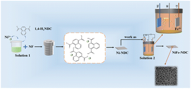
The NiFe-NDC was synthesized by electrodeposition from the Ni-NDC obtained above (Scheme 1). In the solution containing 0.01 M Fe(NO3)3·9H2O and 0.04 M NaF, the NF with Ni-NDC was used as the working electrode, while Pt and Ag/AgCl electrodes were used as counter and reference electrodes, respectively. Then, galvanostatic electrolysis at 1.0 mA cm−2 for 600 s was applied to synthesize NiFe-NDC coated on the surface of NF. The Fe3+ irons were exchanged with Ni2+ irons on the Ni-NDC via electrodeposition. Thus, the NiFe-NDC was synthesized.2.4 Material characterization
X-ray diffraction (XRD) was used to characterize the crystal structure of catalysts. The morphology of the obtained material was characterized by scanning electron microscopy (SEM, FEI Inspect F50) and transmission electron microscopy (TEM, FEIG220). X-ray photoelectron spectrometry (XPS) was applied to examine the chemical valence of elements. Fourier-transform infrared spectra (FT-IR, Nicolet IS50) were used to analyze the surface functional group. Thermogravimetric analysis (TGA) was performed using Netzsch TG 209 F3 Tarsus under the N2 atmosphere. The Brunauer–Emmett–Teller (BET) surface area was measured on a Micromeritics ASAP 2460 instrument. The metal contents of NiFe-NDC were determined by ICP-MS on an Agilent 7800 (MS) instrument.2.5 Electrochemical measurements
Electrochemical measurements were performed using an electrochemical workstation (CHI 660D) with a three-electrode system. The as-prepared NiFe-NDC (1 cm × 1 cm) was used as the working electrode, the platinum sheet (1 cm × 1 cm) was the counter electrode, and the Ag/AgCl electrode was the reference electrode. The electrochemical test was performed in the 1.0 M KOH solution (pH = 13.6). All potentials were converted to the reversible hydrogen electrode (RHE) according to the Nernst equation: E_RHE = E_(Ag/AgCl) + 0.197 V + 0.059 × pH. The linear scanning voltammetry (LSV) measurements were obtained at the scanning rate of 5 mV s−1. All LSV polarization curves were 90% iR-compensation based on the relevant solution ohmic resistance. The Tafel slope was derived from LSV curves and calculated by the formula: η = a + b![[thin space (1/6-em)]](https://www.rsc.org/images/entities/char_2009.gif) log
log![[thin space (1/6-em)]](https://www.rsc.org/images/entities/char_2009.gif) j, where η refers to overpotential, b represents Tafel slope, and j is the current density, respectively. Stability tested for 20 h was at the constant voltage of 1.5144 V vs. RHE. The double-layer capacitance (Cdl) value was acquired by cyclic voltammetry (CV) test at the scan rates of 20, 30, 40, 50, 60, 70, 80, 90, and 100 mV s−1. The electrochemically active surface area (ECSA) is linearly proportional to Cdl. Electrochemical impedance spectroscopy (EIS) was measured over the frequency range from 0.01 to 100
j, where η refers to overpotential, b represents Tafel slope, and j is the current density, respectively. Stability tested for 20 h was at the constant voltage of 1.5144 V vs. RHE. The double-layer capacitance (Cdl) value was acquired by cyclic voltammetry (CV) test at the scan rates of 20, 30, 40, 50, 60, 70, 80, 90, and 100 mV s−1. The electrochemically active surface area (ECSA) is linearly proportional to Cdl. Electrochemical impedance spectroscopy (EIS) was measured over the frequency range from 0.01 to 100![[thin space (1/6-em)]](https://www.rsc.org/images/entities/char_2009.gif) 000 Hz at an open circuit voltage.
000 Hz at an open circuit voltage.
3. Results and discussion
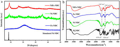
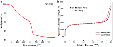
A certain amount of sample was scraped off from the NF for an XRD test to examine the crystal structure of the obtained catalysts. As represented in Fig. 1a, the XRD pattern of NiFe-NDC was well-matched with that of Ni-NDC and consistent with the simulation results in the literature.40 The XRD results indicate successful synthesis of NiFe-NDC. The FT-IR spectrum further revealed the framework structure and demonstrated the successful synthesis of NiFe-NDC. In Fig. 1b, the FT-IR spectrum displayed two peaks at 1587 cm−1 and 1365 cm−1, corresponding to the antisymmetric and symmetric stretching vibrations of –COO− respectively.41 The FT-IR spectrum of the NiFe-NDC represents similar absorption peaks as reported in the references. These two peaks are slightly shifted in the direction of lower wave numbers compared to the peaks of NDC (1678 cm−1 and 1420 cm−1). This is because the carboxylic groups in uncoordinated NDC interacted with metal ions,42 making the charge transfer and leading to the shifting of the C![[double bond, length as m-dash]](https://www.rsc.org/images/entities/char_e001.gif) O stretching frequency from 1678 cm−1 to 1587 cm−1. The FT-IR spectrum reveals the efficient binding of Ni and Fe to the ligand. Moreover, the TGA curve (Fig. 2a) shows the steep weight loss from 109 to 448 °C to give a 26.65% weight remaining, which is due to the removal of absorbed water molecules and the 1,4-NDC ligand. The ultimate products at elevated temperatures (500–800 °C) are likely carbonates of iron or nickel oxide. The N2 adsorption–desorption isotherm (Fig. 2b) was evaluated according to the BET method indicating a surface area of 645 m2 g−1 for NiFe-NDC. The microscopic morphology of NiFe-NDC was characterized by SEM. As shown in Fig. 3a, the Ni-NDC synthesized by the hydrothermal method presents an irregular block shape. Meanwhile, the NiFe-NDC grown in situ on NF is in the form of ultrathin nanosheet arrays and uniformly distributed over the entire NF surface. Fig. 3b and c depict the uniformly distributed nanosheets observed in the scanning SEM of the synthesized NiFe-NDC. From Fig. 3a and b, the modifying effect of introducing metal Fe on the MOF morphology can be seen. After introducing the Fe element, the original bulk MOF is changed into an ultrathin sheet-like structure. These ultrathin 2D nanosheets increase the specific surface area of the catalyst,43,44 resulting in a larger contact area between the catalyst and the electrolyte. Meanwhile, these nanosheets also provide a large number of electroactive sites, suggesting that the electrolyte ions can diffuse to the surface of the active material more quickly.45 At the same time, due to their nanometer thickness, this facilitates mass transport and fast electron transfer.46,47 The microstructure of NiFe-NDC was further investigated using TEM. In Fig. S1,† the nano-array structure of NiFe-NDC can also be further confirmed in the TEM image. The elemental mapping of NiFe-NDC (Fig. S2†) shows that Ni, Fe, and O are uniformly distributed on the NF. This demonstrates the successful binding of metallic Fe to Ni-NDC by electrodeposition.
O stretching frequency from 1678 cm−1 to 1587 cm−1. The FT-IR spectrum reveals the efficient binding of Ni and Fe to the ligand. Moreover, the TGA curve (Fig. 2a) shows the steep weight loss from 109 to 448 °C to give a 26.65% weight remaining, which is due to the removal of absorbed water molecules and the 1,4-NDC ligand. The ultimate products at elevated temperatures (500–800 °C) are likely carbonates of iron or nickel oxide. The N2 adsorption–desorption isotherm (Fig. 2b) was evaluated according to the BET method indicating a surface area of 645 m2 g−1 for NiFe-NDC. The microscopic morphology of NiFe-NDC was characterized by SEM. As shown in Fig. 3a, the Ni-NDC synthesized by the hydrothermal method presents an irregular block shape. Meanwhile, the NiFe-NDC grown in situ on NF is in the form of ultrathin nanosheet arrays and uniformly distributed over the entire NF surface. Fig. 3b and c depict the uniformly distributed nanosheets observed in the scanning SEM of the synthesized NiFe-NDC. From Fig. 3a and b, the modifying effect of introducing metal Fe on the MOF morphology can be seen. After introducing the Fe element, the original bulk MOF is changed into an ultrathin sheet-like structure. These ultrathin 2D nanosheets increase the specific surface area of the catalyst,43,44 resulting in a larger contact area between the catalyst and the electrolyte. Meanwhile, these nanosheets also provide a large number of electroactive sites, suggesting that the electrolyte ions can diffuse to the surface of the active material more quickly.45 At the same time, due to their nanometer thickness, this facilitates mass transport and fast electron transfer.46,47 The microstructure of NiFe-NDC was further investigated using TEM. In Fig. S1,† the nano-array structure of NiFe-NDC can also be further confirmed in the TEM image. The elemental mapping of NiFe-NDC (Fig. S2†) shows that Ni, Fe, and O are uniformly distributed on the NF. This demonstrates the successful binding of metallic Fe to Ni-NDC by electrodeposition.
The electronic structure of elements in NiFe-NDC was investigated by X-ray. Fig. S3† displays the high-resolution O 1s spectrum. It can be fitted by three peaks; the peaks at 530.6, 531.9, and 534.2 eV are related to the (Fe)Ni-O-R, O–C![[double bond, length as m-dash]](https://www.rsc.org/images/entities/char_e001.gif) O, and O–H, respectively. In Fig. 4a, the peaks at 711.9 and 725.2 eV are attributed to Fe 2p3/2 and Fe 2p1/2,48 proving the existence of Fe3+. At 716.5 and 730.7 eV, the peaks can be assigned to the shakeup satellite peaks of Fe3+. The high-resolution XPS spectrum of Ni 2p exhibits four fitting peaks and two satellite peaks corresponding to Ni2+. Two satellite peaks can be observed at 862.3 and 880.9 eV. Peaks at 858.2 and 876.1 eV are allocated to the Ni-OH bands, while the peaks at 855.6 and 873.3 eV are from the Ni–O bands. It is noteworthy that the peak of Ni in NiFe-NDC has shifted to higher binding energies compared to Ni-NDC. In contrast, the binding energies of Fe 2p energy spectra are shifted to negative binding energies than Fe-NDC. As shown in Fig. 4b, the binding energies of Ni(O) 2p3/2 and Ni(O) 2p1/2 increased by 1.0 and 1.1 eV, while the binding energies of Ni(OH) 2p3/2 and Ni(OH) 2p1/2 were increased by 1.5 and 1.7 eV, respectively.49 The result suggests that the electron density of Ni decreased while the positive charge increased after introducing the second metal.50,51 It can be inferred that during the bimetallic doping process, the electrons in the catalyst system are transferred from Ni to Fe,52 and there is a strong coupling between the two.53,54 The interaction between Fe and Co also implies the successful construction of NiFe-NDC, effectively adjusting the local electronic structure of the catalyst. The coupling effect between Ni and Fe is conducive to modulating the electronic environment and improving the electrocatalytic activity of the material.14
O, and O–H, respectively. In Fig. 4a, the peaks at 711.9 and 725.2 eV are attributed to Fe 2p3/2 and Fe 2p1/2,48 proving the existence of Fe3+. At 716.5 and 730.7 eV, the peaks can be assigned to the shakeup satellite peaks of Fe3+. The high-resolution XPS spectrum of Ni 2p exhibits four fitting peaks and two satellite peaks corresponding to Ni2+. Two satellite peaks can be observed at 862.3 and 880.9 eV. Peaks at 858.2 and 876.1 eV are allocated to the Ni-OH bands, while the peaks at 855.6 and 873.3 eV are from the Ni–O bands. It is noteworthy that the peak of Ni in NiFe-NDC has shifted to higher binding energies compared to Ni-NDC. In contrast, the binding energies of Fe 2p energy spectra are shifted to negative binding energies than Fe-NDC. As shown in Fig. 4b, the binding energies of Ni(O) 2p3/2 and Ni(O) 2p1/2 increased by 1.0 and 1.1 eV, while the binding energies of Ni(OH) 2p3/2 and Ni(OH) 2p1/2 were increased by 1.5 and 1.7 eV, respectively.49 The result suggests that the electron density of Ni decreased while the positive charge increased after introducing the second metal.50,51 It can be inferred that during the bimetallic doping process, the electrons in the catalyst system are transferred from Ni to Fe,52 and there is a strong coupling between the two.53,54 The interaction between Fe and Co also implies the successful construction of NiFe-NDC, effectively adjusting the local electronic structure of the catalyst. The coupling effect between Ni and Fe is conducive to modulating the electronic environment and improving the electrocatalytic activity of the material.14
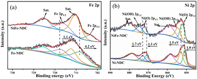 | ||
| Fig. 4 High-resolution XPS spectrums of (a) Fe 2p for Fe-NDC and NiFe-NDC, (b) Ni 2p for Ni-NDC and NiFe-NDC. | ||
The OER activity of NiFe-NDC was measured in the conventional three-electrode system in an alkaline solution (1 M KOH) using linear sweep voltammetry (LSV). NiFe-NDC grown in situ on NF was measured and used directly as the working electrode. Fig. 5a illustrates the LSV polarization curves of pure NF, Ni-NDC, Fe-NDC, NiFe-NDC, and RuO2 under the same conditions. Based on the LSV polarization curves in the figure, it can be quickly concluded that the overpotential of NiFe-NDC (206 mV) is much lower than that of the commercial catalysts RuO2 (240 mV), Ni-NDC (383 mV), Fe-NDC (388 mV), and NF (427 mV) at a current density of 10 mA cm−2, indicating its excellent electrochemical activity. NiFe-NDC outperforms many MOF-based and reported bimetallic OER catalysts (Table S1†). This could be attributed to the bimetallic combination in NiFe-NDC, as well as its two-dimensional lamellar structure,55 which significantly improves the OER activity of the catalyst. Based on the LSV polarization curves, the overpotential and the Tafel slope can be calculated (Fig. 5b). The Tafel slope can provide an essential basis for studying the kinetic mechanism and rate-determining steps of electron transfer in electrocatalytic processes.56 The superior OER performance of NiFe-NDC was evidenced by the smaller Tafel slope (24.64 mV dec−1) derived from the LSV curves of NiFe-NDC compared to RuO2 (50.93 mV dec−1), Ni-NDC (74.95 mV dec−1), and Fe-NDC (98.31 mV dec−1). A smaller Tafel slope indicates a faster increase in current density with a minor change in overpotential, which is a sign of the promising electrocatalyst.57
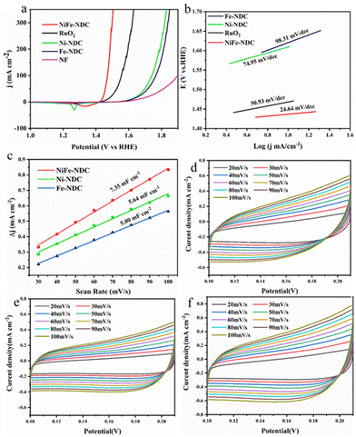 | ||
| Fig. 5 (a) LSV curves of NF, Ni-NDC, Fe-NDC, RuO2, and NiFe-NDC, (b) corresponding Tafel plots, (c) Cdl value, (d) CV curves of Ni-NDC, (e) Fe-NDC, and (f) NiFe-NDC. | ||
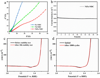
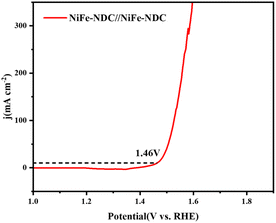
The double-layer capacitance (Cdl) was linearly proportional to the electrochemically active surface area (ECSA).58 The ECSA of NiFe-NDC, Ni-NDC, and Fe-NDC was evaluated based on Cdl (Fig. 5c). The CV curves of Ni-NDC, Fe-NDC, and NiFe-NDC are shown in Fig. 5e and f. The Cdl value is calculated via CV curves and the results suggest that NiFe-NDC possesses a higher Cdl value (7.35 mF cm−2) than that of Ni-NDC (5.64 mF cm−2) and Fe-NDC (5.00 mF cm−2). This indicates that NiFe-NDC has a larger active surface area and more efficient utilization of electroactive sites. The higher Cdl of NiFe-NDC can be attributed to the introduction of bimetallic and its ultrathin two-dimensional nanosheet structure, which increases the specific surface area and facilitates the exposure of more active sites. SEM images of both Ni-NDC and Fe-NDC show a bulk structure. Compared with the bulk structure, the nanosheet structure is more favorable for the exposure of active sites and complete contact with the solution.59 Electrochemical impedance spectroscopy (EIS) reveals the charge transfer kinetics of the OER process.60 As shown in Fig. 6a, the radii of the impedance spectra in the Nyquist plots of Ni-NDC, Fe-NDC, and NiFe-NDC were used to compare the magnitude of the resistance values of the active materials. The plots show that NiFe-NDC has the smallest semicircle among all the samples, indicating that it has the smallest Rct value and its charge transfer and OER reaction kinetics are faster.61 This result confirms that bimetallic doping promotes charge transfer, and doping Fe into it facilitates the increase of the conductivity of the MOF, further reducing the resistance and effectively improving the efficiency of the OER reaction, thus enhancing the electrocatalytic activity of NiFe-NDC. In addition, a two-electrode alkaline water electrolyser was constructed comprising NiFe-NDC//NiFe-NDC electrodes. As illustrated in Fig. 7, the NiFe-NDC//NiFe-NDC electrodes required a potential of only 1.46 V to drive a current density of 10 mA cm−2. This demonstrated the bifunctional electrocatalytic performance of the electrodes.
The durability and stability of NiFe-NDC were evaluated by the prolonged chronopotentiometry test to determine the effectiveness of catalyst application in practice. NiFe-NDC maintained stability throughout the 20 h test at 50 mA cm−2. Fig. 6b and c reveal that the catalyst shows a stable current response in chronoamperometric testing lasting 20 h. As shown in Fig. 6d, 1000 CV cycles were conducted on NiFe-NDC, and its LSV curve largely overlaps with that before the 1000 CV cycles, further revealing the stability of NiFe-NDC.
To further investigate the reason for the high OER activity of NiFe-NDC, its microstructure and electronic changes after electrolysis were investigated by XRD, SEM, XPS, and TEM tests. The powder XRD pattern (Fig. S7†) indicates that the intensity of the diffraction peaks of NiFe-NDC is diminished and the crystallinity is also diminished after the stability test. This may be attributed to the generation of MOOH during the reaction process. After the stability test for 20 h, the two-dimensional sheet structure grown on the surface of NF becomes thicker (Fig. S4†). Still, the original morphology is maintained, proving good stability of NiFe-NDC.
The electronic changes on the electrode surface during the OER process were determined by XPS, and according to the spectra of the XPS investigation in Fig. S5,† the metals Ni and Fe both shifted towards higher binding energies, suggesting that the metals may be oxidized during electrolysis to form MOOH substances, which increased the oxygen adsorption capacity. MOOH is often considered the active center of the OER process.62,63 To further confirm the presence of the generated MOOH, the microcrystalline structure of NiFe-NDC after reaction was investigated by high-resolution TEM (HRTEM). Fig. S6† shows the HRTEM images of NiFe-NDC after OER. Fig. S6a† shows the uniformly distributed state of NiFe-NDC. It can be clearly observed through Fig. S6b† that NiFe-NDC shows lattice streaks with a streak distance of 0.251 nm, consistent with the (101) crystal plane of FeOOH (PDF#26-0792). The TEM results further confirm the generation of FeOOH during the OER process, while FeOOH plays a vital role in the reaction and improves catalytic activity.
4. Conclusions
In summary, the obtained NiFe-NDC performs outstandingly in electrochemical performance testing. The lower overpotential and minor Tafel plot demonstrate its high activity and excellent OER reaction kinetics. The ultrathin two-dimensional structure of the NiFe-NDC significantly increases specific surface area and promotes the exposure of unsaturated metal coordination active centers on the surface. The synergistic interaction between the bimetal effectively optimizes the local electronic structure and accelerates the electron transfer, thus improving the catalytic activity. Meanwhile, FeOOH is generated during the OER process and serves as the catalyst's active substance. The nano-array of NiFe-NDC, the synergistic interaction between the two metals, and the active substance FeOOH enhance the OER reactivity. This research offers insights into the rational design and synthesis of MOFs.Author contributions
Jiaqi He: conceptualization, data curation, writing – original draft. Xin Deng: methodology, data curation. Wenting Sun and Wenjing Shang: formal analysis. Yongbing Lou: resources, supervision, writing – review & editing. Jinxi Chen: resources, supervision, writing – review & editing.Data availability
The data supporting this article have been included as part of the ESI.†Conflicts of interest
There are no conflicts to declare.Acknowledgements
This work was supported by the Priority Academic Program Development of Jiangsu Higher Education Institutions and the Transformation Program of Scientific and Technological Achievements of Jiangsu Province (BA2020060).References
- X. Li, Y. Fang, X. Lin, M. Tian, X. An, Y. Fu, R. Li, J. Jin and J. Ma, J. Mater. Chem. A, 2015, 3, 17392–17402 RSC
.
- N. K. Shrestha, S. A. Patil, S. Cho, Y. Jo, H. Kim and H. Im, J. Mater. Chem. A, 2020, 8, 24408–24418 RSC
.
- G. Li, J. Yu, W. Yu, L. Yang, X. Zhang, X. Liu, H. Liu and W. Zhou, Small, 2020, 16, 2001980 CrossRef CAS PubMed
.
- J. Su, Y. Yang, G. Xia, J. Chen, P. Jiang and Q. Chen, Nat. Commun., 2017, 8, 14969 CrossRef PubMed
.
- X.-F. Lu, P.-Q. Liao, J.-W. Wang, J. X. Wu, X.-W. Chen, C.-T. He, J.-P. Zhang, G.-R. Li and X.-M. Chen, J. Am. Chem. Soc., 2016, 138, 8336–8339 CrossRef CAS PubMed
.
- P. Vijayakumar, S. Lenus, K. Pradeeswari, M. Kumar, J.-H. Chang, M. Kandasamy, M. Krishnamachari, Z. Dai, A. A. Al-Kahtani and P. S. Krishnan, Energy Fuels, 2024, 38, 4504–4515 CrossRef CAS
.
- M. Zhang, Q. Dai, H. Zheng, M. Chen and L. Dai, Adv. Mater., 2018, 30, 1705431 CrossRef
.
- T. Zhao, D. Zhong, Q. Fang, X. Zhao, R. Du, G. Hao, G. Liu, J. Li and Q. Zhao, J. Mater. Sci. Technol., 2024, 189, 183–190 CrossRef
.
- H. R. Yin, X. Q. Liu, L. X. Wang, T. T. Isimjan, D. D. Cai and X. L. Yang, Inorg. Chem., 2024, 63, 7045–7052 CrossRef CAS PubMed
.
- P. Li, H. Yang and Q. Wang, J. Energy Storage, 2024, 84, 110823 CrossRef
.
- Y. Zhang, H. Zhou, P. Zhao, K. Yuan, R. Zhou, Y. Qu and Y. Wang, J. Colloid Interface Sci., 2024, 665, 345–354 CrossRef CAS PubMed
.
- Y. He, Z. Ma, F. Yan, C. Zhu, T. Shen, S. Chou, X. Zhang and Y. Chen, Proc. Natl. Acad. Sci. U. S. A., 2024, 121, e2320777121 CrossRef CAS PubMed
.
- S. Zhao, C. Tan, C.-T. He, P. An, F. Xie, S. Jiang, Y. Zhu, K.-H. Wu, B. Zhang, H. Li, J. Zhang, Y. Chen, S. Liu, J. Dong and Z. Tang, Nat. Energy, 2020, 5, 881–890 CrossRef CAS
.
- C. Cao, D.-D. Ma, Q. Xu, X.-T. Wu and Q.-L. Zhu, Adv. Funct. Mater., 2019, 29, 1807418 CrossRef
.
- S. Ali, P. M. Ismail, M. Humayun, M. Bououdina and L. Qiao, Fuel Process. Technol., 2024, 255, 108049 CrossRef CAS
.
- F. He, Y. Liu, X. Yang, Y. Chen, C. C. Yang, C. L. Dong, Q. He, B. Yang, Z. Li, Y. Kuang, L. Lei, L. Dai and Y. Hou, Nano-Micro Lett., 2024, 16, 175 CrossRef CAS
.
- Y. Li, P. Li, H. Yu, X. Diao, P. Liu, Z. Zhao and X. Chen, J. Colloid Interface Sci., 2024, 665, 1007–1016 CrossRef CAS PubMed
.
- Z. Liang, C. Qu, W. Guo, R. Zou and Q. Xu, Adv. Mater., 2018, 30, 1702891 CrossRef PubMed
.
- H. Lim, H. Kwon, H. Kang, J. E. Jang and H. J. Kwon, Nano-Micro Lett., 2024, 16, 113 CrossRef CAS
.
- C. Wang, S. Wang, Y. Ping, Z. Zhao, D. Guo, D. Wang and X. Bu, Appl. Catal., B, 2024, 347, 123781 CrossRef CAS
.
- J. Yang, Y. Shen, Y. Sun, J. Xian, Y. Long and G. Li, Angew. Chem., Int. Ed., 2023, 62, e202302220 CrossRef CAS PubMed
.
- M. H. Suliman, L. T. Alfuhaid, A. Khan, M. Usman and A. Helal, Fuel, 2024, 363, 131044 CrossRef CAS
.
- W. Zhou, D.-D. Huang, Y.-P. Wu, J. Zhao, T. Wu, J. Zhang, D.-S. Li, C. Sun, P. Feng and X. Bu, Angew. Chem., Int. Ed., 2019, 58, 4227–4231 CrossRef CAS PubMed
.
- S. Wang, Q. Li, S. Sun, K. Ge, Y. Zhao, K. Yang, Z. Zhang, J. Cao, J. Lu, Y. Yang, Y. Zhang, M. Pan, Z. Lin and L. Zhu, J. Mater. Chem. A, 2022, 10, 5350–5360 RSC
.
- X.-L. Wang, L.-Z. Dong, M. Qiao, Y.-J. Tang, J. Liu, Y. Li, S.-L. Li, J.-X. Su and Y.-Q. Lan, Angew. Chem., Int. Ed., 2018, 57, 9660–9664 CrossRef CAS PubMed
.
- S. S. Shah, A. Albadrani, M. Fettouhi, M. A. Aziz and A. Helal, Chem. – Asian J., 2024, 19, e202301039 CrossRef
.
- Y. Guo, C. Zhang, J. Zhang, K. Dastafkan, K. Wang, C. Zhao and Z. Shi, ACS Sustainable Chem. Eng., 2021, 9, 2047–2056 CrossRef CAS
.
- Y. Chen, P. Liao, K. Jin, Y. Zheng, H. Shao and G. Li, Inorg. Chem. Front., 2023, 10, 6489–6505 RSC
.
- X.-Y. Wang, M. Zhu, Q.-N. Bian, B.-S. Guo, W.-Q. Kong, C.-B. Wang and Y.-Y. Feng, ACS Appl. Nano Mater., 2023, 6, 5200–5210 CrossRef CAS
.
- A. Muthurasu, A. P. Tiwari, K. Chhetri, B. Dahal and H. Y. Kim, Nano Energy, 2021, 88, 106238 CrossRef CAS
.
- W. Ahn, M. G. Park, D. U. Lee, M. H. Seo, G. Jiang, Z. P. Cano, F. M. Hassan and Z. Chen, Adv. Funct. Mater., 2018, 28, 1802129 CrossRef
.
- Y. Wang, Z. Y. Zhou, Y. Z. Lin, Y. Z. Zhang, P. Y. Bi, Q. Q. Jing, Y. D. Luo, Z. D. Sun, J. J. Liao and Z. Gao, Chem. Eng. J., 2023, 462, 142179 CrossRef CAS
.
- M. Yang, Y.-N. Zhou, Y.-N. Cao, Z. Tong, B. Dong and Y.-M. Chai, Appl. Mater. Today, 2020, 20, 100692 CrossRef
.
- Y. Hao, Q. Liu, Y. Zhou, Z. Yuan, Y. Fan, Z. Ke, C.-Y. Su and G. Li, Energy Environ. Mater., 2019, 2, 18–21 CrossRef CAS
.
- A. Fateeva, P. Horcajada, T. Devic, C. Serre, J. Marrot, J.-M. Greneche, M. Morcrette, J.-M. Tarascon, G. Maurin and G. Ferey, Eur. J. Inorg. Chem., 2010,(24), 3789–3794 CrossRef CAS
.
- Y. Xu, M. Xie, X. Li, F. Shao, S. Li, S. Li, Y. Xu, J. Chen, F. Zeng and Y. Jiao, J. Colloid Interface Sci., 2022, 626, 426–434 CrossRef CAS
.
- M. Etesami, S. R. Motlagh, R. Khezri, M. Gopalakrishnan, J. Theerthagiri, M. Y. Choi, K. Nootong, A. Somwangthanaroj and S. Kheawhom, Energy Chem., 2024, 6, 100128 CrossRef CAS
.
- W. Tan, H. He, Y. Gao, Y. Peng and X. Dai, J. Colloid Interface Sci., 2021, 600, 492–502 CrossRef CAS PubMed
.
- Y. Xu, M. Xie, X. Li, F. Shao, S. Li, S. Li, Y. Xu, J. Chen, F. Zeng and Y. Jiao, J. Colloid Interface Sci., 2022, 626, 426–434 CrossRef CAS
.
- Y. Lou, J. Chen, J. Jiang and Q. Bao, Dalton Trans., 2014, 43, 1261–1266 RSC
.
- Q. Zha, F. Yuan, G. Qin and Y. Ni, Inorg. Chem., 2020, 59, 1295–1305 CrossRef CAS
.
- G. Wang, Z. Yan, N. Wang, M. Xiang, Z. Xu and H. Zhu, J. Mater. Res., 2022, 37, 1714–1726 CrossRef CAS
.
- H. Xu, X. Wei, H. Zeng, C. Jiang, Z. Wang, Y. Ouyang, C. Lu, Y. Jing, S. Yao and F. Dai, Nano Res., 2023, 16, 8614–8637 CrossRef CAS
.
- Z. Xu, C.-L. Yeh, J.-L. Chen, J. T. Lin, K.-C. Ho and R. Y.-Y. Lin, ACS Sustainable Chem. Eng., 2022, 10, 11577–11586 CrossRef CAS
.
- G. T. Hai, Z. P. Tao, H. Y. Gao, J. Zhao, D. D. Jia, X. B. Huang, X. Chen, X. D. Xue, S. H. Feng and G. Wang, Nano Energy, 2021, 79, 105418 CrossRef CAS
.
- G. Hai, X. Jia, K. Zhang, X. Liu, Z. Wu and G. Wang, Nano Energy, 2018, 44, 345–352 CrossRef CAS
.
- L. Zhang, J. Wang, K. Jiang, Z. Xiao, Y. Gao, S. Lin and B. Chen, Angew. Chem., Int. Ed., 2022, 61, e202214794 CrossRef CAS
.
- J. Zhou, Z. Han, X. Wang, H. Gai, Z. Chen, T. Guo, X. Hou, L. Xu, X. Hu, M. Huang, S. V. Levchenko and H. Jiang, Adv. Funct. Mater., 2021, 31, 2102066 CrossRef CAS
.
- C.-F. Li, L.-J. Xie, J.-W. Zhao, L.-F. Gu, H.-B. Tang, L. Zheng and G.-R. Li, Angew. Chem., Int. Ed., 2022, 61, e202116934 CrossRef CAS
.
- Q. Qian, Y. Li, Y. Liu, L. Yu and G. Zhang, Adv. Mater., 2019, 31, 1901139 CrossRef
.
- W. Li, W. Fang, W. Chen, K. Dinh, H. Ren, L. Zhao, C. Liu and Q. Yan, J. Mater. Chem. A, 2020, 8, 3658–3666 RSC
.
- S. Mao, L. Ye, S. Jin, C. Zhou, J. Pang and W. Xu, Inorg. Chem., 2024, 63, 6005–6015 CrossRef CAS PubMed
.
- X. Ling, F. Du, Y. Zhang, Y. Shen, W. Gao, B. Zhou, Z. Wang, G. Li, T. Li, Q. Shen, Y. Xiong, X. Wang, Y. Zhou and Z. Zou, J. Mater. Chem. A, 2021, 9, 14607–14607 RSC
.
- W. Zhang, M. Niu, J. Yu, S. Li, Y. Wang and K. Zhou, Adv. Funct. Mater., 2023, 33, 202302014 Search PubMed
.
- M.-J. Liu, F.-H. Yang, J.-C. Mei, X. Guo, H.-Y. Wang, M.-Y. He, Y.-A. Yao, H.-F. Zhang and C.-B. Liu, Nanomaterials, 2023, 13, 2421 CrossRef CAS PubMed
.
- Z. Zou, M. Cai, X. Zhao, J. Huang, J. Du and C. Xu, J. Mater. Chem. A, 2019, 7, 14011–14018 RSC
.
- M. Zeng and Y. Li, J. Mater. Chem. A, 2015, 3, 14942–14962 RSC
.
- C. Zhang, Q. Qi, Y. Mei, J. Hu, M. Sun, Y. Zhang, B. Huang, L. Zhang and S. Yang, Adv. Mater., 2023, 35, 2208904 CrossRef CAS
.
- J. Tian, F. Jiang, D. Yuan, L. Zhang, Q. Chen and M. Hong, Angew. Chem., Int. Ed., 2020, 59, 13101–13108 CrossRef CAS
.
- Y. Zhao, X. F. Lu, Z.-P. Wu, Z. Pei, D. Luan and X. W. Lou, Adv. Mater., 2023, 35, 2207888 CrossRef CAS
.
- W.-C. Hu, Y. Shi, Y. Zhou, C. Wang, M. R. Younis, J. Pang, C. Wang and X.-H. Xia, J. Mater. Chem. A, 2019, 7, 10601–10609 RSC
.
- S. Yu, N. Zhang, J. Li, J. Yin, Y. Wang, Z. Wu, Y. Zhang and Y. Du, ACS Sustainable Chem. Eng., 2024, 12, 4551–4564 CrossRef CAS
.
- Y. Li, T. Bo, S. Zuo, G. Zhang, X. Zhao, W. Zhou, X. Wu, G. Zhao, H. Huang, L. Zheng, J. Zhang, H. Zhang and J. Zhang, Angew. Chem., Int. Ed., 2023, 62, e2023093 Search PubMed
.
Footnote |
| † Electronic supplementary information (ESI) available. See DOI: https://doi.org/10.1039/d4dt01656d |
| This journal is © The Royal Society of Chemistry 2024 |

