 Open Access Article
Electrochemical approach of the reductive activation of O2 by a nonheme FeII complex. Some clues for the development of catalytic oxidations†
Antoine
Bohn
a,
Amanda Lyn
Robinson
a,
Katell
Sénéchal-David
a,
Christian
Herrero
a,
Frédéric
Kanoufi
 b,
Elodie
Anxolabéhère-Mallart
 c and
Frédéric
Banse
 *a
*a
aUniversité Paris-Saclay, CNRS, Institut de Chimie Moléculaire et des Matériaux d'Orsay, 91400, Orsay, France. E-mail: frederic.banse@universite-paris-saclay.fr
bInterfaces, Traitements, Organisation et Dynamique des Systèmes, Université de Paris, CNRS, F-75013 Paris, France
cLaboratoire d'Electrochimie Moléculaire, Université de Paris, CNRS, F-75013 Paris, France
First published on 2nd September 2024
Abstract
We report an in-depth study of the reductive activation of O2 by the nonheme [FeII(L25)(MeCN)]2+ complex carried out by cyclic voltammetry. Experimental evidence is obtained for the slow coordination of dioxygen to the ferrous center yielding an FeII/O2 adduct with a strong FeII–O2 character rather than an FeIII–superoxo one. Electron injection in the FeII–O2 species occurs at a potential of ca. −700 mV vs. SCE, i.e. 200 mV above the O2 to O2˙− reduction, leading to the formation of a FeIII–peroxo intermediate and then FeIII–hydroperoxo upon protonation by residual water. The experimental CVs recorded at variable scan rate or variable FeII concentration are well simulated taking into account a detailed mechanism initiated by the competitive reduction of O2 and the FeII–O2 adduct. Analysis of the concentration of the reaction intermediates generated as a function of the applied potential indicates that the FeIII–peroxo intermediate significantly accumulates at a potential of −650 mV. Oxidative bromination of anisole is assayed under electrolytic conditions at this potential to yield bromoanisole products. The low faradaic yields observed reveal that deleterious reactions such as direct reduction of reaction intermediates likely occur. Based on the detailed mechanism elucidated, a number of improvements to achieve more efficient catalytic reactions can be proposed.
Introduction
Oxidation reactions are used on a large scale for the synthesis of many commodities from abundant hydrocarbon feedstock.1 However, these transformations are commonly performed with stoichiometric amounts of potent oxidizing reagents, thereby leading to the generation of huge amounts of side products.2,3 Alternatively, dioxygen can be used as an oxidant but high temperature and pressure are required for its activation in order to bypass the spin forbidden reaction with singlet (S = 0) spin state organic molecules.4 Due to the inherent conditions under which aerobic oxidations are carried out, they are energy consuming and frequently non selective at the same time. On the other hand, in Nature, many oxidative transformations are performed by metalloenzymes under physiological conditions. These natural systems are therefore an extraordinary source of inspiration for chemists interested in the development of sustainable oxidations. These enzymes activate dioxygen at a redox metal center in their active site (generally iron or copper) to generate potent oxidizing intermediates capable of oxygenating metabolites/xenobiotics with high efficiency and selectivity.5–8 In the case of the nonheme iron enzymes Rieske dioxygenases, the metal center promotes the controlled reduction of O2via two sequential electron transfers from the terminal reductant NAD(P)H to generate the reactive oxidizing species. The catalytic cycle is initiated by the coordination of O2 to the reduced FeII active site yielding a FeIII–superoxo (FeIII(OO˙)) intermediate which then undergoes an electron/proton transfer leading to an FeIII–hydroperoxo (FeIII(OOH)) complex. It is proposed that this latter intermediate directly performs the oxygen atom transfers to the substrate or after heterolytic O–O cleavage to yield an active FeV–oxo–hydroxo (FeV(O)(OH)).9–12 Similar steps are encountered in the mechanism of many oxygenases with various active sites, i.e. dinuclear in methane monooxygenase13 or heme in cytochromes P450.14 In each case, O2 activation relies on the controlled input of reducing equivalents at the active site to ensure the formation of the oxidizing reaction intermediates. Eventually, the electron injection is only possible in the presence of the target substrate which serves as a fuse for the oxidizing species and allows preventing their direct reduction by the electron source and self-oxidation of the protein matrix at the same time.15 Interestingly, nonheme α-ketoglutarate dependent halogenases catalyze the conversion of C–H into C–Cl or C–Br bonds following a similar dioxygen activation in the presence of halides (however, with some differences regarding the electron source and oxidation state of the active intermediate).16,17Despite a comprehensive understanding of the mechanisms in Nature, it is difficult to reproduce this so-called reductive activation of O2 with synthetic complexes that lack an elaborate supramolecular organisation allowing the orchestration of electron and proton consumption with the efficient oxidation of the substrate.18,19 In contrast, to achieve the catalytic oxidation of small organic molecules by dioxygen, synthetic iron(II) complexes frequently promote autoxidation reactions instead of activating O2via inner sphere electron transfer.20,21 The cases of catalytic O2 activation by nonheme iron(II) complexes are rare and implement α-hydroxy acids22,23 or the organic substrate24 as sacrificial electron donors, mimicking alpha-ketoglutarate dependent enzymes5 or tryptophan 2,3-dioxygenase,25,26 respectively. Regarding the first category of catalysts, it was shown that the catalytic efficacy is limited due to the proton-induced catalyst deactivation or the competitive oxidation of α-hydroxy acids. For the second category, the catalytic systems are unselective, yielding a variety of products and the reactions proceed slowly and require thermal activation. Given the difficulty of controlling O2 reactivity, reduced forms of oxygen, such as peroxides, are generally used in biomimetic studies with iron complexes.3,8,27
Electrochemical methods have been only scarcely used to deliver the electrons required for O2 activation.28 However, such methods potentially present several benefits: (i) a better control of the reaction steps, thanks to the analytical information that can be gathered from the electrical current; and (ii) a minimization of the reaction by-products, thanks to the use of O2 as oxidant and the absence of a chemical reducing agent. Implementing a combination of electrochemical and spectroscopic techniques, we have demonstrated that non-heme29 or heme30 iron(III)–peroxo intermediates can indeed be generated at the electrode surface following this approach. More recently, we have reported on the epoxidation or chlorination of cyclooctene upon O2 electrochemical reductive activation by a Mn porphyrin complex.31
FeII complexes with neutral tetradentate (N4) or pentadentate (N5) amine/pyridine ligands are frequently used for the activation of chemical oxidants in order to perform catalytic oxidations, mechanistic investigations or the characterization of their reaction-intermediates.3,32,33 These complexes are generally air-stable but can activate O2 in the presence of a convenient hydrogen donor or electron donor/acid combination.34–38 In the particular case of Fe/L25 systems (L25 = N,N,N′-tris(2-pyridylmethyl)-N′-methyl-ethane-1,2-diamine) in the presence of air and ascorbate, single-strand cleavage on plasmid DNA was observed.39 Therefore, such complexes appear as relevant precursors for the development of catalytic oxidations by dioxygen under electrolytic conditions. Additionally, using the FeII(L25) precursor, (hydro)peroxo and oxo–iron species can be generated in high yield and isolated to serve as reference species for the mechanistic study of oxygen activation.
In this paper, we report a thorough mechanistic investigation of the reaction of O2 with the FeII(L25) complex by cyclic voltammetry (CV). Capitalizing on this study, attempts were made to brominate anisole. While our results indicate that this type of complex cannot efficiently activate O2 under electrolytic conditions, they provide valuable indications for the development of more efficient catalysts following this strategy.
Results and discussion
Previous work in our lab demonstrated that the reaction of [FeII(L25)(MeCN)]2+ (1) (Scheme 1) with H2O2 leads to the accumulation of [FeIII(OOH)(L25)]2+ which displays a reversible acid/base equilibrium with [FeIII(OO)(L25)]+.40–42 We have also previously reported that the reaction of 1 with single O-atom donors (PhIO, mCPBA) quantitatively yielded [FeIV(O)(L25)]2+.43 Being able to generate, accumulate and, in some cases purify these reaction intermediates, allowed us to study their electrochemical and spectroscopic properties (see ESI, Fig. S3 and S4†). Therefore, the established reactivity of 1 and the electrochemical and spectroscopic data for the reactive species mentioned above can be used as benchmarks for the reaction between 1 and O2 under reductive conditions.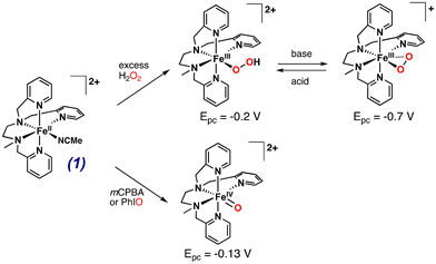 | ||
| Scheme 1 Reactivity of complex 1, [FeII(L25)(MeCN)]2+ with different chemical oxidants to form iron–oxygen species. Redox potentials are given vs. SCE. | ||
Behaviour of complex 1 in presence of dioxygen: nature of the FeII–O2 adduct
In MeCN at 20 °C, [FeII(L25)(MeCN)]2+ (1) displays a reversible FeIII/FeII wave at E1/2 = 0.94 V vs. SCE and a quasi-reversible FeII/FeI wave at −1.64 V (Fig. S1†). The FeIII/FeII redox potential largely exceeds the arbitrary threshold value for the direct reaction of a non-heme FeII complex with O2 which was estimated to be ca. 0.3 V vs. SCE.44 In line with this value, the FeII complex 1 is air stable. Indeed, bubbling O2 in an acetonitrile solution over 24 hours at room temperature does not lead to any modification (intensity or shape) of the t2g(FeII)-to-π*(pyridines) charge transfer band (data not shown). However, some complexes displaying potentials significantly larger than 0.3 V actually react with O2,45,46 as it was recently argued that the FeIII/FeII redox potential value is not the only criterion to consider, but that the rate constant for the reaction of an FeII center with O2 must also be taken into account.19 Complex 1 displays a significant lability due to a LS (S = 0) to HS (S = 2) equilibrium with a 70%/30% distribution in solution at room temperature, as determined by magnetic moment measurement via the Evans method (Fig. S2†). Thus, 1 is susceptible to bind with O2 following a reversible reaction to yield a FeII/O2 adduct. As reported earlier, the description of FeII/O2 species requires to consider multiple configurations.47,48 For simplification, we only consider the two extreme ones corresponding to ferrous–dioxygen (FeII–O2, Pauling description)49,50 and ferric–superoxo (FeIII(OO˙), Weiss description).51 Here, an FeIII(OO˙) species does not accumulate upon reaction between 1 and O2, as evidenced by the lack of new spectroscopic feature which is expected in that case.52–56 Therefore, we tentatively propose that the FeII/O2 adduct displays a strong FeII–O2 character rather than an FeIII(OO˙) one. This proposition is in line with the high FeIII/FeII redox potential: the FeII center is not reducing enough to transfer an electron to the bound O2 molecule, and the forward reaction in the 1 + O2 ⇄ FeII–O2 equilibrium is likely to be slow as no spectroscopic changes are evidenced. Unlike UV-vis spectroscopy, cyclic voltammetry operates under a dynamic regime, thus providing information on the formation of a FeII–O2 species. Under argon, the normalized intensity of the anodic peak of the FeIII/FeII wave for 1 recorded at various scan rates is constant indicating that the concentration of 1 probed at the electrode is not dependent on the scan rate (Fig. 1C). By contrast, this evolution recorded in the presence of O2 is not linear, in line with the presence of an additional FeII species in equilibrium with 1 + O2, i.e. an FeII–O2 adduct (Fig. 1 and ESI, Scheme S1† for rationalization of the CVs using a square scheme mechanism). Even if the coordination of O2 appears unfavored, electron injection in the FeII–O2 species is expected to drive the reaction towards intermediates susceptible to participate in the oxidative transformations of substrates.Reduction of dioxygen in the presence of 1: mechanistic analysis
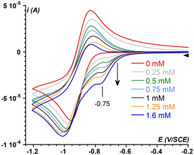
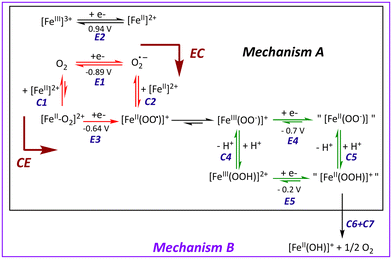
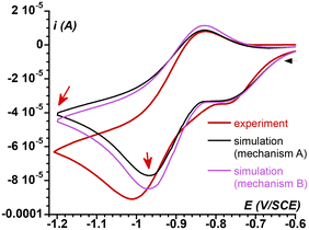
To test this assumption, the CV of O2 (1.6 mM in MeCN)57 was recorded in the presence of increasing amounts of 1, up to one equiv. vs. O2 (Fig. 2). As soon as 1 is introduced in the solution, the O2/O2˙− redox wave (E1/2 = −0.89 V, red trace) is modified with the development of a cathodic signal at Epc = −0.75 V, the intensity of which depends on the concentration in 1. At the same time, the progressive loss of O2/O2˙− reversibility is observed. Similar observations were made with a related complex, [FeII(TPEN)]2+ (TPEN = N,N,N′,N′-tetrakis(2-pyridylmethyl)ethane-1,2-diamine), where the current intensity at −0.75 V was modelled and assigned to the reduction of the FeII–O2 adduct.29 Thus, the mechanism which was previously proposed to model the CVs of oxygenated solutions of [FeII(TPEN)]2+ can serve as basis to the case of complex 1. This mechanism is shown in Scheme 2. It involves two square schemes, where electrochemical reactions (E) are represented as horizontal processes and chemical reactions (C) as vertical ones (Mechanism A in the black frame). The red square leads to a formal FeII–superoxide intermediate FeII(OO˙) via either the reduction of the FeII–O2 adduct (CE pathway), or the coordination of O2˙−, formed upon reduction of molecular oxygen at the electrode, to the FeII complex (EC pathway). The CE pathway reflects the development of the cathodic wave at −0.75 V, whereas the loss of reversibility of the O2/O2˙− wave in the presence of 1 supports the EC pathway. Additionally, since the FeII(OO˙) species is not detected on the reverse scan (the cathodic wave at −0.75 V is not associated with an anodic signature), it is assumed that this species quickly evolves into its valence tautomer FeIII–peroxo moiety (FeIII(OO−)). This latter FeIII(OO−) species is the starting point of the second square scheme. In the green square scheme, the FeIII(OO−) intermediate undergoes either a CE pathway via FeIII(OOH) or EC pathway to a putative FeII–hydroperoxo species, where protons are supplied by the residual water present in the medium.‡This mechanism was validated by simulating the experimental CVs. To limit the number of variable parameters, the CVs of the stable species (1, O2) and independently generated intermediates ([FeIII(L25)(OOH)]2+, [FeIII(L25)(OO)]+ and [FeIV(L25)(O)]2+) were simulated separately beforehand to determine some of the standard potentials (E°) and electron transfer rates (k0) (see ESI, Fig. S3 and S4† for the characterization of reaction intermediates and Fig. S15–S17† for experimental CVs and their simulation). As shown in Fig. 3, a satisfying simulation is obtained considering Mechanism A with the parameters listed in ESI, Fig. S5.† However, two key features observed in the experimental CVs are not well reproduced in the simulated ones. The reduction peak of O2 into O2˙− at ca. −1 V is not as intense in the simulation as it is in the experimental CV and the current intensity at the starting potential in the backward scan (−1.2 V) is likewise less intense in the simulation (see red arrows in Fig. 3). These observations indicate that the concentration of O2 considered in Mechanism A is not large enough. Since [O2] is fixed to 1.6 mM in the simulation, corresponding to its solubility in MeCN,57 the discrepancies between the simulated CV and the experimental data indicate that some O2 is regenerated during the process, contributing to the current intensity. Therefore, additional reactions must be included to complement the mechanism.
We have recently reported that the one electron reduction of [FeIII(L25)(OOH)]2+ results in the disproportionation of the hydroperoxo ligand to release O2 (eqn (1)).58,59
| 2[FeIII(OOH)(L25)]2+ + 2e− → 2[FeII(OH)(L25)]+ + O2 | (1) |
The [FeIII(L25)(OOH)]2+ species is characterized by a cathodic peak at −0.2 V (ESI, Fig. S3†). As the reactions described in Mechanism A are triggered when the electrode is polarized at a potential below −0.7 V, i.e. lower than −0.2 V, the [FeIII(L25)(OOH)]2+ must be readily reduced once formed, releasing dioxygen. Therefore, Mechanism A was modified to account for the disproportionation of [FeII(L25)(OOH)]+, yielding Mechanism B (Scheme 2 and Fig. 3 and ESI Fig. S6†). As expected, the Mechanism B results in a simulated CV that has a more intense cathodic peak at ca. −1 V for the reduction of O2, and the reoxidation of O2˙− on the backward scan is likewise more negative. However, a discrepancy between the simulated CV with the experimental one still persists, indicating that the disproportionation of [FeII(L25)(OOH)]+ does not account for all of the dioxygen probed at the electrode.
Considering all of the redox couples, written as horizontal reactions in Scheme 2, and their potential values (E° values indicated in Fig. S6, ESI†), it is clear that O2˙− is the most reducing species. A simplified diagram indicating the E° values for the different redox couples is shown in Scheme 3. It highlights that reaction of O2˙− with oxidizing species such as [FeIII(L25)(OO)]+ or [FeIII(L25)(OOH)]2+ will regenerate O2 at the vicinity of the electrode. At the same time, FeII species such as [FeII(L25)(OO)] or [FeII(L25)(OOH)]+ will be released. The latter intermediate being susceptible to disproportionate into [FeII(L25)(OH)]+ and O2 (eqn (1)), thereby leading to an increase of the cathodic current intensity at ca. −1 V. Moreover, in acetonitrile, the initial complex [FeII(L25)(MeCN)]2+ (1) can be easily regenerated from [FeII(L25)(OH)]+ to close the catalytic loop and initiate another series of reactions.
 | ||
| Scheme 3 Scale of negative redox potential values for the species involved in Mechanism B. All potential values are referred to SCE. | ||
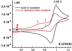
Fig. 4 presents the CVs response characterizing the oxidation of the species either present (black trace) in the oxygenated solution of 1, or (red trace) produced near the electrode during a first cathodic cycle down to −1.2 V (i.e. as in Fig. 2). The CV of the pristine oxygenated solution of 1 (black trace) shows the signature of the reversible oxidation of [FeII(L25)(MeCN)]2+ (1) into [FeIII(L25)(MeCN)]3+. When the same solution is first cycled towards the reduction peak of O2, the oxidative signature of [FeII(L25)(MeCN)]2+ (1) significantly decreases in intensity by a factor of ca. 2. Additionally, a broad oxidation wave between 0.6 and 0.8 V appears, which is consistent with the presence in solution of [FeII(L25)(OH)]+ (Ep,a = 0.66 V) and [FeII(L25)(OH2)]2+ (Ep,a = 0.84 V) as inferred from the electrochemical response of the reaction products of 1 with H2O and a base (ESI, Fig. S7†). Because the total intensity for these two CVs (black and red traces, Fig. 4) is identical, this supports that [FeII(L25)(OH)]+ and [FeII(L25)(OH2)]2+ are issued from the disproportionation reaction discussed above and that the regeneration of [FeII(L25)(MeCN)]2+ (1) from these species is slow on the CV timescale.
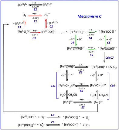
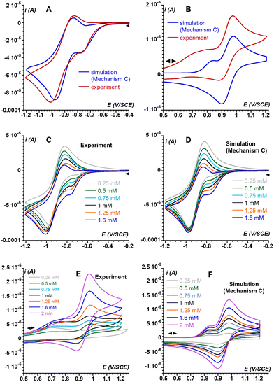
Thus, the series of redox reactions that implicate superoxide and FeIII complexes (C8 and C9 in Scheme 4) as well as the chemical equilibria involving the FeII complexes evoked above (C10) and their FeIII counterparts (C11) were considered.§ The new mechanism (Mechanism C) was used to further simulate the electrochemical response of the system under investigation. The parameters implemented in the simulations are tabulated in ESI Fig. S8† resulting in simulated CV that very satisfactorily matches the experimental CV on the negative potential range as well as the current intensity of the backward scan (Fig. 5A and B). To further check the validity of Mechanism C, CVs of solutions containing different O2/1 stoichiometric ratios were recorded and compared to their simulations based on Mechanism C. As displayed in Fig. 5C and D for the negative-potential region, and Fig. 5E and F for the positive region, the agreement is very good.
Interestingly, CVs recorded at various scan rates are also nicely simulated using Mechanism C (ESI, Fig. S9†). Thus, the most prominent electrochemical and chemical phenomena related to O2 activation by 1 are encompassed in Mechanism C, which rules out the involvement of high valent FeIV(O) species.¶ Therefore, such a species has not been considered to avoid over-parametrization of the system.
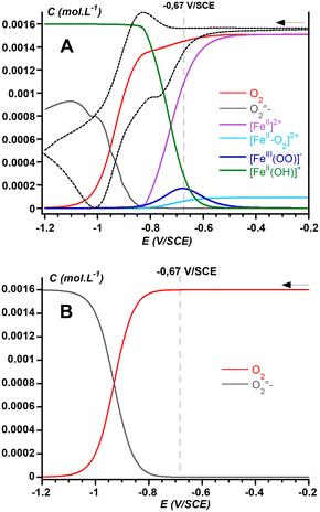
The further advantage of the CV simulation is that it allows better insights into the composition of the solution near the electrode surface, which provides important information for the development of electro-assisted oxidation reactions. Fig. 6 shows the evolution of the concentration of the predominant species generated at the electrode when a solution of 1 and O2 is scanned from −0.2 V to −1.2 V vs. SCE. It depicts that consumption of O2 (red trace) starts from ca. −0.6 V together with that of the FeII precursor 1 (purple trace). At the same time, the concentration in peroxo species FeIII(OO−) increases and reaches its maximum at a potential of −0.67 V (dark blue). Interestingly, at this potential the direct production of superoxide from O2 is negligible (see Fig. 6B), therefore showing that the FeIII(OO−) intermediate is obtained via the CE pathway (Scheme 2), i.e. via steps catalyzed by the metal complex. For more negative potentials, the concentration of the FeIII(OO−) peroxo species decreases while [FeII(OH)]+ accumulates (green trace), reflecting the disproportionation of the [FeII(OOH)] species formed by the reduction of the FeIII(OOH) complex. This latter intermediate is obtained by protonation of the FeIII(OO−) species by residual water. While the generation of the FeIII(OOH) is supported by the overall Mechanism C, its concentration remains very low because water is a weak acid, and because it is readily reduced at such low potential values.
Finally, Mechanism C indicates that O2 activation by complex 1 involves two successive single electron transfers to generate FeIII–peroxo species, which is reminiscent of Rieske dioxygenases12,60 and P450.14 In P450 enzymes, the FeIII(OOH) Cpd0 evolves via O–O heterolysis towards CpdI, a formal FeV(O), which oxygenates the substrate while it is not yet clear whether the O-atom transfer activity is performed by the FeIII(OOH) species in Rieske dioxygenases or whether it requires cleavage of the O–O bond. In our study, we found no evidence of O–O bond cleavage.
Attempted application in electrolysis for anisole bromination
This speciation of species is determined under CV conditions under diffusion regime, without stirring of the solution. It can be inferred that stirring may alter these concentration profiles and may help in transporting these species in the bulk solution where steady-state concentration could be reached.Despite the fact that FeII(L25) and related complexes are efficient catalysts for the oxygenation of small organic substrates by H2O2,61–65 our initial attempts to perform the electro-assisted oxygenation of small organic substrates such as ethylbenzene or cyclooctene in the presence of 1 were unsuccessful. At best, only trace amounts of products were obtained under these conditions. On an other hand, Vardhaman et al. reported that non-heme FeIII(OOH) (obtained by reaction of a FeII precursor and excess H2O2) supported by pentadentate ligands were efficient oxidants for halides (I−, Br−, Cl−) and could ultimately lead to the halogenation of aromatic molecules such as phenol red or anisole.66,67 In line with these observations, we performed the spectrophotometric monitoring of the reaction of phenol red with Br− in the presence of 1 and H2O2 to demonstrate that it indeed led to bromophenol blue (ESI, Fig. S10†). While the CVs simulation provided herein shows that the FeIII(OOH) intermediate does not accumulate significantly, it can be generated in situ by protonation of its FeIII(OO−) conjugate base. Thus, we decided to assess our system in an aromatic bromination reaction. For this purpose, we used pure O2 instead of air in order to increase the concentration of O2 (8 mM)57 and favor the formation of the FeII–O2 and subsequent species, as well as a large excess of water as proton source and a carbon foam working electrode to significantly increase the electrode surface area (see ESI,† Materials and methods for complete experimental details). Based on the CV analysis, we performed the preparative scale electrolysis at −650 mV where the FeIII(OO−) intermediate is at its maximum concentration. Because phenol red is redox active at −600 mV vs. SCE, anisole was chosen as an alternative terminal aromatic hydrocarbon substrate.
Determination of the charge accumulated during the electrolysis of different reaction mixtures over 2 hours is depicted in ESI, Fig. S11.† In general, the presence of complex 1, as well as the presence of water, led to a larger exchange of electrons. When both the complex and water were present, an equivalent of 3.1 mM electrons were exchanged in 2 hours, whereas it was slightly lower in the absence of water (Table 1, compare entries 1 and 2). Of note, the amount of Br-anisole formed is much lower than the amount of electrons supplied by the electrode, translating into a low faradaic yield. These observations indicate that most of the electrons are used for unproductive side reactions, such as reduction of reaction intermediates. Control experiments show that some products can be obtained in the absence of complex, but the faradaic yield exceeds 100% (entry 4), suggesting that some radical reactions are also likely to interfere in the process.|| These radical processes are probably initiated by the generation of small amounts of superoxide at the electrode surface.
| Entry | Compositiona1![[thin space (1/6-em)]](https://www.rsc.org/images/entities/char_2009.gif) : :![[thin space (1/6-em)]](https://www.rsc.org/images/entities/char_2009.gif) anisole anisole![[thin space (1/6-em)]](https://www.rsc.org/images/entities/char_2009.gif) : :![[thin space (1/6-em)]](https://www.rsc.org/images/entities/char_2009.gif) Br− Br−![[thin space (1/6-em)]](https://www.rsc.org/images/entities/char_2009.gif) : :![[thin space (1/6-em)]](https://www.rsc.org/images/entities/char_2009.gif) H2O H2O |
[e−] (mM) | e−/FeII | [Product]b (mM) | Faradic yieldc |
|---|---|---|---|---|---|
| a 1 mM in 1 when present, TBABr used as Br− source. b A mixture of the 3-bromoanisole is obtained, only the concentration of the main product is indicated. c Faradic yield = (2 × [product]/[e−]) × 100. | |||||
| 1 | 1![[thin space (1/6-em)]](https://www.rsc.org/images/entities/char_2009.gif) : :![[thin space (1/6-em)]](https://www.rsc.org/images/entities/char_2009.gif) 100 100![[thin space (1/6-em)]](https://www.rsc.org/images/entities/char_2009.gif) : :![[thin space (1/6-em)]](https://www.rsc.org/images/entities/char_2009.gif) 100 100![[thin space (1/6-em)]](https://www.rsc.org/images/entities/char_2009.gif) : :![[thin space (1/6-em)]](https://www.rsc.org/images/entities/char_2009.gif) 250 250 |
3.1 | 3.1 | 4-Br-anisole, 0.10 mM | 6.5% |
| 2 | 1![[thin space (1/6-em)]](https://www.rsc.org/images/entities/char_2009.gif) : :![[thin space (1/6-em)]](https://www.rsc.org/images/entities/char_2009.gif) 100 100![[thin space (1/6-em)]](https://www.rsc.org/images/entities/char_2009.gif) : :![[thin space (1/6-em)]](https://www.rsc.org/images/entities/char_2009.gif) 100 100![[thin space (1/6-em)]](https://www.rsc.org/images/entities/char_2009.gif) : :![[thin space (1/6-em)]](https://www.rsc.org/images/entities/char_2009.gif) 0 0 |
2.3 | 2.3 | 4-Br-anisole, 0.04 mM | 3.5% |
| 3 | 0![[thin space (1/6-em)]](https://www.rsc.org/images/entities/char_2009.gif) : :![[thin space (1/6-em)]](https://www.rsc.org/images/entities/char_2009.gif) 100 100![[thin space (1/6-em)]](https://www.rsc.org/images/entities/char_2009.gif) : :![[thin space (1/6-em)]](https://www.rsc.org/images/entities/char_2009.gif) 100 100![[thin space (1/6-em)]](https://www.rsc.org/images/entities/char_2009.gif) : :![[thin space (1/6-em)]](https://www.rsc.org/images/entities/char_2009.gif) 250 250 |
1.1 | — | — | — |
| 4 | 0![[thin space (1/6-em)]](https://www.rsc.org/images/entities/char_2009.gif) : :![[thin space (1/6-em)]](https://www.rsc.org/images/entities/char_2009.gif) 100 100![[thin space (1/6-em)]](https://www.rsc.org/images/entities/char_2009.gif) : :![[thin space (1/6-em)]](https://www.rsc.org/images/entities/char_2009.gif) 100 100![[thin space (1/6-em)]](https://www.rsc.org/images/entities/char_2009.gif) : :![[thin space (1/6-em)]](https://www.rsc.org/images/entities/char_2009.gif) 0 0 |
0.5 | — | 2-Br-anisole, 0.26 mM | 104% |
Lessons learned from the mechanistic analysis, the catalysis results, and possible improvements
A major drawback of the present system is that the activation of O2 (reactions E3 and C3 in Scheme 4) corresponds to a simultaneous 2-electron transfer to dioxygen yielding the FeIII(OO−) intermediate. This activation is triggered at a low potential, close to or below the reduction of FeIII(OO−) or FeIII(OOH) intermediates, respectively (reactions E4 and E5), resulting in the instability of these species. By contrast, in oxygenase enzymes, the two electron transfers are made sequentially which ensures the step-by-step progress of the catalytic cycle. To overcome this major drawback of the current system and achieve more efficient catalysis, the potentials at which the two electron transfers take place need to be tuned to each other.First, using a more donating (i.e. anionic) ancillary ligand may stabilize FeIII over FeII, hence significantly decreasing the FeIII/FeII redox potential (E2 in Scheme 4) and promoting the coordination of O2 to FeII by favoring an FeII to O2 electron transfer. Thus, the first electron injection in O2 would be triggered at a potential shifted toward more positive values, i.e. at the potential where FeII is generated, farther from the O2/O2˙− wave, resulting in a gain in energy and avoiding the generation of superoxide anions at the same time. In these conditions, the FeII/O2 adduct would exhibit a predominant FeIII(OO˙) character instead of a FeII–O2 one as in the present system. It is also conceivable that the use of an anionic ligand could lower the redox potential of the FeIII(OO−) and FeIII(OOH) intermediates (reactions E4 and E5) to allow their generation following electron transfer to the FeIII(OO˙) species while preventing their reduction, as observed in the current system. Along this line, starting from the heme FeIII(F20TPP)Cl/O2 system, it has recently been shown that the injection of two electrons ultimately yielded a FeIV(O) intermediate after O–O cleavage in a proposed FeIII(OOH) intermediate.68
A second possibility for tuning the redox potentials of the two electron transfers to O2 would be to combine two different iron complexes so that each successively transfers one electron to dioxygen. We have evidenced this approach to be relevant for the aerobic sulfoxidation of thioanisole at a potential as high as −340 mV vs. SCE. In this reported study, we used a tandem system made of an FeIII complex bearing an aminophenolato dianionic ligand designed to ensure the injection of the first electron to O2, and of a FeII complex with a polyazadentate ligand to ensure the second electron transfer leading to a FeIII–peroxo moiety.69
In addition to the electronic effects related to the first coordination sphere of the metal centre, the presence of functional groups aimed at developing hydrogen bonds in the second coordination sphere can provide further energy gain. For example, the presence of an OH group on the L25 ligand resulted in a significant positive shift of the cathodic peak of the FeII–O2 adduct, allowing to carry out the electroassisted oxidation of thioanisole at −500 mV vs. SCE.70
Finally, as the precise adjustment of the potentials associated with the 2 electron transfers may be difficult to achieve, pulsed electrolysis offers a complementary approach, where the application of short voltage steps at different potentials may allow the generation of reactions intermediates at applied potential E1 and their preservation at applied potential E2 to favour their reaction with the substrate. This methodology has recently been implemented in electrochemical CO2 reduction.71
Conclusions
The detailed mechanism of reductive O2 activation by [FeII(L25)(MeCN)]2+ (1) has been determined using a complete analysis and simulation of CVs. For consistency, this analysis was preliminary benchmarked by studying the electrochemical properties of the reaction intermediates that can be generated and stabilized from the FeII precursor. The generation of FeIII(OO−) and FeIII(OOH) intermediates is evidenced but this latter species does not accumulate significantly since O2 activation is triggered at a potential where its reduction is favoured.This system was assessed in preparative scale electrolysis for the bromination of anisole at a potential where the FeIII(OO−) intermediate is at its maximum concentration. While halogenation products are obtained, the faradaic yield is low indicating the occurrence of many unproductive side reactions. Taking advantage of the detailed mechanism, ways of improvement can be envisioned. Efforts in that sense are currently under investigation in our laboratory.
Data availability
The data used for this article are available on request from the authors.Conflicts of interest
There are no conflicts to declare.Acknowledgements
This work was supported by the Agence Nationale de la Recherche (GOAL Project, ANR-22-CE07-0037-01).Notes and references
- J. H. Teles, W. Partenheimer, R. Jira, F. Cavani, G. Strukul, R. Hage, J. W. Boer, L. Gooßen, P. Mamone and O. A. Kholdeeva, Oxidation, in Applied Homogeneous Catalysis with Organometallic Compounds: A Comprehensive Handbook in Four Volumes, Third Edition, Wiley, 1st edn, 2017, vol. 64 Search PubMed.
- T. A. Nijhuis, M. Makkee, J. A. Moulijn and B. M. Weckhuysen, Ind. Eng. Chem. Res., 2006, 45, 3447–3459 CrossRef CAS.
- G. Olivo, O. Cussó, M. Borrell and M. Costas, J. Biol. Inorg. Chem., 2017, 22, 425–452 CrossRef CAS.
- F. Cavani and J. H. Teles, ChemSusChem, 2009, 2, 508–534 CrossRef CAS PubMed.
- S. Kal and L. Que, J. Biol. Inorg. Chem., 2017, 250, 625–627 Search PubMed.
- E. I. Solomon, D. E. Heppner, E. M. Johnston, J. W. Ginsbach, J. Cirera, M. Qayyum, M. T. Kieber-Emmons, C. H. Kjaergaard, R. G. Hadt and L. Tian, Chem. Rev., 2014, 114, 3659–3853 CrossRef CAS.
- A. J. Jasniewski and L. Que, Chem. Rev., 2018, 118, 2554–2592 CrossRef CAS.
- X. Huang and J. T. Groves, Chem. Rev., 2018, 118, 2491–2553 CrossRef CAS.
- Y. Wang, J. Li and A. Liu, J. Biol. Inorg. Chem., 2017, 22, 395–405 CrossRef.
- P. C. A. Bruijnincx, G. van Koten and R. J. M. Klein Gebbink, Chem. Soc. Rev., 2008, 37, 2716 RSC.
- B. S. Rivard, M. S. Rogers, D. J. Marell, M. B. Neibergall, S. Chakrabarty, C. J. Cramer and J. D. Lipscomb, Biochemistry, 2015, 54, 4652–4664 CrossRef PubMed.
- M. E. Runda, N. A. W. de Kok and S. Schmidt, ChemBioChem, 2023, 24, e202300078 CrossRef.
- V. C. C. Wang, S. Maji, P. P. Y. Chen, H. K. Lee, S. S. F. Yu and S. I. Chan, Chem. Rev., 2017, 117, 8574–8621 CrossRef.
- B. Meunier, S. P. de Visser and S. Shaik, Chem. Rev., 2004, 104, 3947–3980 CrossRef.
- T. L. Poulos, Chem. Rev., 2014, 114, 3919–3962 CrossRef PubMed.
- F. H. Vaillancourt, E. Yeh, D. A. Vosburg, S. Garneau-Tsodikova and C. T. Walsh, Chem. Rev., 2006, 106, 3364–3378 CrossRef CAS PubMed.
- A. Timmins and S. P. de Visser, Catalysts, 2018, 8, 314–325 CrossRef.
- S. Sahu and D. P. Goldberg, J. Am. Chem. Soc., 2016, 138, 11410–11428 CrossRef CAS PubMed.
- D. C. Lacy, Inorg. Chem. Front., 2019, 6, 2396–2403 RSC.
- P. Comba, Y.-M. Lee, W. Nam and A. Waleska, Chem. Commun., 2014, 50, 412 RSC.
- M. Sankaralingam, Y.-M. Lee, W. Nam and S. Fukuzumi, Inorg. Chem., 2017, 56, 5096–5104 CrossRef CAS.
- S. Chatterjee, S. Bhattacharya and T. K. Paine, Inorg. Chem., 2018, 57, 10160–10169 CrossRef CAS PubMed.
- B. N. Sánchez-Eguía, J. Serrano-Plana, A. Company and M. Costas, Chem. Commun., 2020, 56, 14369–14372 RSC.
- G. Liao, F. Mei, Z. Chen and G. Yin, Dalton Trans., 2022, 51, 18024–18032 RSC.
- J. Geng, A. C. Weitz, K. Dornevil, M. P. Hendrich and A. Liu, Biochemistry, 2020, 59, 2813–2822 CrossRef CAS PubMed.
- J. Basran, E. S. Booth, M. Lee, S. Handa and E. L. Raven, Biochemistry, 2016, 55, 6743–6750 CrossRef CAS PubMed.
- J. Chen, W. Song, Y.-M. Lee, W. Nam and B. Wang, Coord. Chem. Rev., 2023, 477, 214945 CrossRef CAS.
- E. Anxolabéhère-Mallart and F. Banse, Curr. Opin. Electrochem., 2019, 15, 118–124 CrossRef.
- N. Ségaud, E. Anxolabéhère-Mallart, K. Sénéchal-David, L. Acosta-Rueda, M. Robert and F. Banse, Chem. Sci., 2014, 6, 639–647 RSC.
- R. Oliveira, W. Zouari, C. Herrero, F. Banse, B. Schöllhorn, C. Fave and E. Anxolabéhère-Mallart, Inorg. Chem., 2016, 55, 12204–12210 CrossRef CAS PubMed.
- N. Kostopoulos, F. Banse, C. Fave and E. Anxolabéhère-Mallart, Chem. Commun., 2021, 57, 1198–1201 RSC.
- S. M. Hözl, P. J. Altmann, J. W. Kück and F. E. Kühn, Coord. Chem. Rev., 2017, 352, 517–536 CrossRef.
- M. Guo, T. Corona, K. Ray and W. Nam, ACS Cent. Sci., 2018, 5, 13–28 CrossRef.
- F. Li, K. M. V. Heuvelen, K. K. Meier, E. Münck and L. Que, J. Am. Chem. Soc., 2013, 135, 10198–10201 CrossRef CAS PubMed.
- A. Thibon, J. England, M. Martinho, V. G. Young, J. R. Frisch, R. Guillot, J.-J. Girerd, E. Münck, L. Que and F. Banse, Angew. Chem., Int. Ed., 2008, 47, 7064–7067 CrossRef CAS.
- M. Martinho, G. Blain and F. Banse, Dalton Trans., 2010, 39, 1630 RSC.
- Y.-M. Lee, S. Hong, Y. Morimoto, W. Shin, S. Fukuzumi and W. Nam, J. Am. Chem. Soc., 2010, 132, 10668–10670 CrossRef CAS PubMed.
- S. Hong, Y.-M. Lee, W. Shin, S. Fukuzumi and W. Nam, J. Am. Chem. Soc., 2009, 131, 13910–13911 CrossRef CAS PubMed.
- P. Mialane, A. Nivorojkine, G. Pratviel, L. Azéma, M. Slany, F. Godde, A. Simaan, F. Banse, T. Kargar-Grisel, G. Bouchoux, J. Sainton, O. Horner, J. Guilhem, L. Tchertanova, B. Meunier and J.-J. Girerd, Inorg. Chem., 1999, 38, 1085–1092 CrossRef CAS.
- A. J. Simaan, F. Banse, P. Mialane, A. Boussac, S. Un, T. Kargar-Grisel, G. Bouchoux and J. J. Girerd, Eur. J. Inorg. Chem., 1999, 993–996 CrossRef CAS.
- A. J. Simaan, S. Döpner, F. Banse, S. Bourcier, G. Bouchoux, A. Boussac, P. Hildebrandt and J.-J. Girerd, Eur. J. Inorg. Chem., 2000, 1627–1633 CrossRef CAS.
- A. J. Simaan, F. Banse, J.-J. Girerd, K. Wieghardt and E. Bill, Inorg. Chem., 2001, 40, 6538–6540 CrossRef CAS.
- A. Bohn, C. Chinaux-Chaix, K. Cheaib, R. Guillot, C. Herrero, K. Sénéchal-David, J.-N. Rebilly and F. Banse, Dalton Trans., 2019, 48, 17045–17051 RSC.
- S. Hong, Y.-M. Lee, K. Ray and W. Nam, Coord. Chem. Rev., 2017, 334, 25–42 CrossRef CAS.
- Y.-M. Chiou and L. Que, J. Am. Chem. Soc., 1995, 117, 3999–4013 CrossRef CAS.
- M. P. Mehn, K. Fujisawa, E. L. Hegg and L. Que, J. Am. Chem. Soc., 2003, 125, 7828–7842 CrossRef CAS.
- K. P. Jensen and U. Ryde, J. Biol. Chem., 2004, 279, 14561–14569 CrossRef CAS.
- K. P. Jensen, B. O. Roos and U. Ryde, J. Inorg. Biochem., 2005, 99, 45–54 CrossRef CAS PubMed.
- L. Pauling and C. D. Coryell, Proc. Natl. Acad. Sci. U. S. A., 1936, 22, 210–216 CrossRef CAS.
- L. Pauling, Nature, 1964, 203, 182–183 CrossRef CAS.
- J. J. Weiss, Nature, 1964, 202, 83–84 CrossRef CAS.
- X. Shan and L. Que, Proc. Natl. Acad. Sci. U. S. A., 2005, 102, 5340–5345 CrossRef CAS.
- F. Oddon, Y. Chiba, J. Nakazawa, T. Ohta, T. Ogura and S. Hikichi, Angew. Chem., 2015, 127, 7444–7447 CrossRef.
- C.-W. Chiang, S. T. Kleespies, H. D. Stout, K. K. Meier, P.-Y. Li, E. L. Bominaar, L. Que, E. Münck and W.-Z. Lee, J. Am. Chem. Soc., 2014, 136, 10846–10849 CrossRef CAS.
- C. Winslow, H. B. Lee, M. J. Field, S. J. Teat and J. Rittle, J. Am. Chem. Soc., 2021, 143, 13686–13693 CrossRef CAS.
- A. A. Fischer, S. V. Lindeman and A. T. Fiedler, Chem. Commun., 2018, 54, 11344–11347 RSC.
- J. M. Achord and C. Hussey, Anal. Chem., 1980, 52, 601–602 CrossRef CAS.
- A. Bohn, K. Sénéchal-David, J. Rebilly, C. Herrero, W. Leibl, E. Anxolabéhère-Mallart and F. Banse, Chem. – Eur. J., 2022, 28, e202201600 CrossRef CAS PubMed.
- H. P. H. Wong, F. Banse and S. P. de Visser, ChemCatChem, 2023, 15, e202300957 CrossRef CAS.
- S. M. Barry and G. L. Challis, ACS Catal., 2013, 3, 2362–2370 CrossRef CAS.
- V. Balland, D. Mathieu, N. Pons-Y-Moll, J.-F. Bartoli, F. Banse, P. Battioni, J.-J. Girerd and D. Mansuy, J. Mol. Catal. A: Chem., 2004, 215, 81–87 CrossRef CAS.
- N. Ségaud, J.-N. Rebilly, K. Sénéchal-David, R. Guillot, L. Billon, J.-P. Baltaze, J. Farjon, O. Reinaud and F. Banse, Inorg. Chem., 2013, 52, 691–700 CrossRef.
- A. Thibon, J.-F. Bartoli, S. Bourcier and F. Banse, Dalton Trans., 2009, 9587 RSC.
- A. Thibon, J.-F. Bartoli, R. Guillot, J. Sainton, M. Martinho, D. Mansuy and F. Banse, J. Mol. Catal. A: Chem., 2008, 287, 115–120 CrossRef CAS.
- R. Bercy, J. Rebilly, C. Herrero, R. Guillot, H. Maisonneuve and F. Banse, Eur. J. Inorg. Chem., 2023, 26, e202300236 CrossRef CAS.
- A. K. Vardhaman, C. V. Sastri, D. Kumar and S. P. de Visser, Chem. Commun., 2011, 47, 11044 RSC.
- A. K. Vardhaman, P. Barman, S. Kumar, C. V. Sastri, D. Kumar and S. P. de Visser, Chem. Commun., 2013, 49, 10926–10923 RSC.
- N. Kostopoulos, C. Achaibou, J.-M. Noël, F. Kanoufi, M. Robert, C. Fave and E. Anxolabéhère-Mallart, Inorg. Chem., 2020, 59, 11577–11583 CrossRef CAS PubMed.
- A. L. Robinson, J.-N. Rebilly, R. Guillot, C. Herrero, H. Maisonneuve and F. Banse, Chem. – Eur. J., 2022, e202200217 CrossRef CAS.
- A. L. Robinson, E. Bannermann, R. Guillot, C. Herrerro, K. Sénéchal-David, E. Rivière, F. Banse and J.-N. Rebilly, Eur. J. Inorg. Chem., 2024, 27, e202300694 CrossRef CAS.
- F. Greenwell, B. Siritanaratkul, P. K. Sharma, E. H. Yu and A. J. Cowan, J. Am. Chem. Soc., 2023, 145, 15078–15083 CrossRef CAS.
Footnotes |
| † Electronic supplementary information (ESI) available: Materials and methods, complete experimental procedures, CV simulations. See DOI: https://doi.org/10.1039/d4dt01870b |
| ‡ Despite the use of dry acetonitrile, the concentration of water has been estimated to be 2 mM (see ESI,† “CV simulations” section). For electrolysis experiments its concentration has been increased. This is the only source of protons used in this study, as the optimization of proton-related parameters, i.e. acid strength and its delivery in the reaction mixture (one-shot or by using a syringe pump), nature of the conjugate base (coordinating or non-coordinating), corresponds to a complete study in itself. |
| § The equilibria between the FeIII/II(NCCH3), FeIII/II(OH2) and FeIII/II(OH) have been restricted to FeIII/II(NCCH3) and FeIII/II(OH) for the sake of simplification (C10 and C11 in Scheme 4 and Fig. S8†). For the same reason, redox reactions have been restricted to two FeIII/FeII couples (E2 and E6 in Scheme 4 and Fig. S8†). |
| ¶ Disproportionation of [FeII(L25)(OOH)]+ at −50 °C has been shown to proceed through heterolytic cleavage of the O–O bond yielding an unstable FeIV(O) intermediate before release of [FeII(L25)(OH)]+ and O2 (see ref. 58). This highly reactive FeIV(O) species is unlikely to accumulate significantly at 20 °C to contribute to the current intensity. |
| || Along the same line, we noticed that the H2O2-dependent bromination of phenol red catalyzed by 1 is more efficient under air than under argon. |
| This journal is © The Royal Society of Chemistry 2024 |


