 Open Access Article
Triboelectric nanogenerator based on electrospun molecular ferroelectric composite nanofibers for energy harvesting†
Swati
Deswal
 a,
Shima
Arab
a,
Nanfei
He
a,
Shima
Arab
a,
Nanfei
He
 b,
Wei
Gao
b,
Bongmook
Lee
ac and
Veena
Misra
*a
b,
Wei
Gao
b,
Bongmook
Lee
ac and
Veena
Misra
*a
aDepartment of Electrical and Computer Engineering, North Carolina State University, Raleigh, NC, USA. E-mail: vmisra@ncsu.edu
bDepartment of Textile Engineering, Chemistry and Science, North Carolina State University, Raleigh, NC 27606, USA
cCollege of Engineering, SUNY Polytechnic Institute, Utica, NY, USA
First published on 15th April 2024
Abstract
Ceramic-based ferroelectric materials have long been used as functional ferroelectric materials for applications in triboelectric-energy harvesting. However, their drawbacks (brittleness, energy-intensive fabrication methods, and minimal mechanical flexibility) have intensified the search for alternatives where flexible form factors are needed. Molecular ferroelectrics are an emerging class of multifunctional materials. To date, the intriguing piezo/ferroelectric properties of these materials have led to the construction of piezoelectric nanogenerators. However, their numerous advantages warrant their expansion towards triboelectric nanogenerators (TENGs). We aimed to demonstrate the potential of a molecular ferroelectric, diisopropylammonium bromide (DIPAB), in the realm of triboelectric-energy harvesting. Combining ferroelectric properties with enhanced surface modification, we designed an electrospun-based TENG comprising DIPAB/P(VDF-TrFE) as an active negative layer. The synergistic effects emanating from highly aligned polymeric chains and ferroelectric particles in conjunction with a high surface area of the as-designed TENG generated an output voltage of 203.8 V and resulted in a maximum power density of 416.2 mW m−2 when operated in contact separation mode. Its practical application as a sustainable power supply for low-power electronics was demonstrated through powering of commercial electrolytic capacitors and LEDs. This study presents a reliable, cost-effective, and readily scalable method for enhancing TENG performance. This strategy holds potential for application of TENGs in wearable biomechanical-energy harvesting, and paves the way for further advances involving a sustainable energy solution for wearable electronics.
1 Introduction
In the era of the “Internet of Things, in which the demand for portable and wearable electronics is rapidly evolving, providing pervasive, sustainable sources of power supply poses a significant challenge.1–5 Conventional batteries face issues with rigidity, restricted lifespan, and significant environmental harm, which limits their extended use in the realm of wearable electronics. Thus, tapping into the abundant mechanical energies present in the operational surroundings of electronic devices could be a long-lasting solution. Therefore, a huge impetus is driven towards diverse energy-harvesting technologies that utilize different effects (e.g., thermoelectric, piezoelectric, electromagnetic, pyroelectric and triboelectric).6–14 Among several energy-harvesting technologies being explored, triboelectric nanogenerators (TENGs) hold great promise because of their extensive versatility. Ease of fabrication, distinct device design, wide array of material availability and remarkable power-conversion efficiencies render them highly attractive towards the escalating problems that the energy sector is facing.14,15The broad spectrum of triboelectric materials includes metals, metal oxides, two-dimensional (2D) materials, coordination polymers, metal–organic frameworks (MOFs), covalent–organic frameworks (COFs), ferroelectric materials and natural substances. However, composition based on ferroelectric properties confers substantial advantages over composition based on other properties.16 In addition to their impressive dielectric properties that allow for excellent charge retention, the inherent electric field aids in the generation and efficient accumulation of charges during TENG operation, thereby enhancing energy efficiency.17,18 In addition, bestowed with the inherent features of pyroelectricity and piezoelectricity, the construction of multimodal devices capable of performing tasks beyond energy generation is possible.19,20 Governed by these aspects of multifunctionality, ferroelectric materials have been researched intensely in the field of triboelectric nanogenerators. The exploration of ferroelectrics is restricted mainly to inorganic materials such as lead zirconate titanate (PZT),21 lead magnesium niobate-lead titanate (PMN-PT),22 and barium titanate (BTO)23 owing to the outstanding properties they demonstrate. Nonetheless, their rigid structure, composition with toxic elements, inability of homogeneous-solution formation and high-temperature processing hinder their widespread deployment in wearable and flexible devices.
We wished to explore a class of materials that could benefit from structural tunability, processability of low-temperature solutions, and mechanical flexibility. We envisioned that recent breakthroughs in molecular ferroelectrics (MFs) with properties comparable with those of inorganics could lay promising foundations for TENG devices.24 For instance, diisopropylammonium bromide (DIPAB) is a molecular ferroelectric which has spontaneous polarization of 23 μC cm−2 (very close to that of the inorganic counterpart BTO), a high Tc of 426 K (above that of BTO) and room temperature high dielectric constant of 85. Hence, DIPAB could be a candidate for expanding TENG functionality.25
When considering integration of a material into a TENG, embedding the material does not ensure optimal performance. Several additional features beyond embedment are crucial for enhancing the efficiency and functionality of the TENG. Materials with large differences in their electron affinity and work function exhibit strong triboelectric effects, leading to high output voltages and high power generation.26,27 Besides the choice of material, the surface morphology and texture of the embedded material can significantly influence the contact area and contact force between triboelectric layers, which affects the overall efficiency of triboelectric charging. Features such as roughness, nanostructures, and surface patterning can enhance contact electrification and improve TENG performance.28,29 The interfacial properties between the embedded material and substrate or other triboelectric layers are crucial for promoting effective charge transfer and minimizing charge leakage. To obtain a polymer matrix with high surface roughness and high surface-to-volume ratio, electrospinning is highly attractive.30 It not only increases the contact surface, but also adjusts dipole orientations so that higher polarizability and a higher dielectric constant can be achieved. To accomplish this, herein we combine the unique advantages of electrospinning and remarkable features of an organic ferroelectric, DIPAB, to formulate an electrospun DIPAB/P(VDF-TrFE) composite film as a negative triboelectric layer. This is the first time an examination of DIPAB/P(VDF-TrFE) has been conducted. P(VDF-TrFE) was selected as the polymer matrix because of its enhanced ferroelectric properties combined with its excellent electronegativity, chemical stability and biocompatibility. P(VDF-TrFE) facilitates the formation of the piezoelectrically active β-phase (with an all-trans TTTT configuration) more readily than P(VDF) alone. This is because the incorporation of TrFE monomers introduces steric hindrance, thereby preventing formation of the non-polar α-phase with a TGTG configuration. Consequently, a flexible TENG device operating in contact separation mode was fabricated by employing polycaprolactone (PCL) as the positive layer. The performance of the device was comprehensively investigated as a function of filler concentration, which provided an optimal DIPAB loading of 5 wt% to exhibit an output voltage of 203.8 V. The energy harvested from the best-performing device was examined for its efficacy in driving low-power electronics. Furthermore, the energy-harvesting capabilities of the device were validated through various biomechanical motions, including hand tapping, jumping, and jogging. This work demonstrated that molecular ferroelectrics such as DIPAB is a promising triboelectric material for constructing high-performance TENGs which also offers enormous possibilities for further exploration.
2 Experimental section
2.1 Materials
DIPAB, N,N-dimethylformamide (DMF) and polycaprolactone were purchased from MilliporeSigma (USA) and used without further purification. All chemicals used were ACS/reagent grade. Poly(vinylidene fluoride co-trifluoroethylene) [P(VDF-TrFE)] (FC 30) (powder with 70 mol% of vinylidene fluoride and 30 mol% of trifluoroethylene) was obtained from Piezotech (France). Cu/Ni conductive textile tape and copper adhesive tape were acquired from Amazon (USA). Powder X-ray diffraction (PXRD) was undertaken on a SmartLab X-Ray Diffractometer (Rigaku, Japan) on fibers. The surface morphologies and thicknesses of fibers were characterized with the help of an SU8700 field-emission scanning electron microscope (Hitachi, Japan). To quantify the fiber diameter across different samples, we employed ImageJ 1.54d (National Institutes of Health, USA) software. After establishing a precise scale based on image magnification, we manually measured the diameter of 50 individual fibers within each scanning electron microscopy (SEM) image using the built-in measuring tool available in ImageJ. Dielectric measurements were acquired from the 4284A Precision LCR Meter (Agilent Technologies, USA). The surface roughness of DIPAB/P(VDF-TrFE) fiber mats was examined using a VKx1100 confocal laser scanning microscope (Keyence, Japan). The microscope was set to 20× magnification, offering a spatial resolution of 130 nm and slice resolution of 0.5 nm. To study the presence of the β-phase in formulated films, Fourier transform infrared (FTIR) spectroscopy was done using a Cary 630 FTIR spectrometer (Agilent Technologies).2.2 Preparation of the PCL layer
The PCL film was prepared by dissolving 1 g of PCL in 10 mL of chloroform. The solvent mixture was stirred at room temperature until a homogeneous solution was obtained. Subsequently, the well-mixed solution was poured into a glass Petri dish and left overnight to dry, following which a smooth film was obtained. For device fabrication, the film was laid into dimensions of 2.7 × 2.7 cm2.2.3 Preparation of DIPAB/P(VDF-TrFE) fibers
First, the solution for electrospinning was prepared by dissolving 15 wt% P(VDF-TrFE) powder in DMF followed by heating the mixture at 75 °C for 6 h. Subsequently, DIPAB powders of different wt% (3, 5, 10 and 15 wt%) calculated to P(VDF-TrFE) in the mixture were added to the above solution and left to stir at 75 °C overnight. Following the dissolution of DIPAB, a homogeneous solution was obtained, which was then fed into a 10 mL syringe in the electrospinning setup (ESR200R2D; NanoNC, USA) using a 23-gauge stainless-steel needle. All electrospinning parameters were executed at ambient conditions of temperature and humidity. The drum collector rotating at 1500 rpm was covered with aluminum foil and placed at 20 cm from the needle. The feed rate was maintained at 0.5 mL h−1 and a positive voltage of 17 kV was applied between the needle and collector. All fibers from different polymer solutions were collected on the foil for 7 h. Finally, electrospun mats were cut into dimensions of 2.7 × 2.7 cm2 and transferred onto copper tapes for the fabrication of TENG device.2.4 Fabrication and characterization of the TENG device
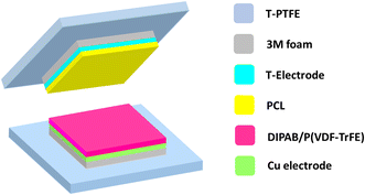
To fabricate the TENG device, the as-prepared electrospun DIPAB/P(VDF-TrFE) fiber mat affixed to copper electrodes of dimensions 2.7 × 2.7 cm2 was employed as a negative layer. Similarly, the conductive textile was attached to one end of the PCL film of an equivalent dimension and utilized as the positive layer. Subsequently, the electrodes were attached to 3M foam tapes and then stacked onto a textile, polytetrafluoroethylene (T-PTFE), which acted as a substrate (Fig. 1). The attachment of 3M foam tape aids effective contact between layers and buffers the impact. Finally, both tribolayers were fixed on opposite sides and electrical contacts were established at the ends of electrodes with the help of Cu wires to capture signals.The mechanical-energy harvesting performance of the fabricated devices was evaluated using a linear motor (E1100 series; LinMot, Switzerland) working in contact and separation mode. The gap between the two tribomaterials was configured at a distance of 5 mm. The electrical-output signals (Voc and Isc) and transferred charges were measured by an electrometer (6514 series; Keithley Instruments, USA). A programmed interface (LabVIEW, USA) was employed to acquire real-time data.
3 Results and discussion
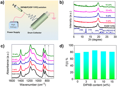
Owing to the remarkable ferroelectric properties of high spontaneous polarization (23 μC cm−2), high Tc (426 K) and dielectric constant (85 at room temperature), together with solution processability, the molecular ferroelectric DIPAB was employed for energy-harvesting studies in this work.25 DIPAB exists as two polymorphs at room temperature: 1-F (ferroelectric phase) and 1-P (paraelectric phase). In 1-F, DIPAB crystallizes in a monoclinic crystal system with the chiral space group P21. In 1-P, it belongs to an orthorhombic system with the P212121 space group. To manoeuvre the ferroelectric attributes of DIPAB in this work, we obtained the 1-F phase by heating its crystalline powder to 428 K for 5 min (Fig. S1†).25As the initial step, different compositions of DIPAB with P(VDF-TrFE) were chosen to formulate electrospun fiber films for TENGs. A schematic illustration of our electrospinning process is depicted in Fig. 2a. As revealed from the XRD profile, all films had an intense diffraction peak centered at 19.5°, corresponding to the characteristic β-phase of P(VDF-TrFE) (Fig. 2b). Notable signs of a non-polar α-phase could not be observed, thereby indicating the high amenability of composed films towards energy-harvesting applications. As the DIPAB concentration increased from 3 wt% to 15 wt%, characteristic peaks arising from the organic ferroelectric could be evidenced. The 5 wt% film delineated a higher peak intensity, indicating a greater level of crystallization in the β-phase.
To further evaluate the crystallinity and examine the enhancement of the β-phase in prepared fiber films, FTIR spectroscopy was done on all wt% fiber mats (Fig. 2c). According to the literature, the vibration band at 846 cm−1 was assigned to the β-phase and the one at 765 cm−1 originated from the non-polar α-phase.31 All the films as seen in Fig. 2c exhibited an intense band at 846 cm−1, confirming the high content of the obtained β-phase as part of the fabrication process. Quantification of the polar β-phase was determined using the following equation.
The surface morphologies of fibers prepared at different concentrations were characterized by SEM (Fig. 3a and b). The micrographs revealed the formation of smooth bead-free fibers up to 5 wt% DIPAB/P(VDF-TrFE) (Fig. S2†), beyond which beads were generally observed. This finding suggests jet instability during electrospinning at higher concentrations (10 wt% and 15 wt%). Bead formation disrupts uniform deposition of the polymer solution, leading to non-ideal fiber morphology. The distribution of the fibers is shown in Fig. S3.† The diameters of fibers decreased gradually as a function of filler loading up to 5 wt%. This was attributed mainly to the rise in charge density owing to DIPAB particles, which influenced the electric-field strength of the DIPAB/P(VDF-TrFE) solution markedly.32 The filler ferroelectric particles could readily acquire charge under the high voltage, consequently amplifying the electrospinning jet's propelling force and leading to reduced diameters in DIPAB/P(VDF-TrFE) fiber mats. The thickness of the formulated fiber films was ∼23 μm as revealed by the cross-section SEM image (Fig. S4†).
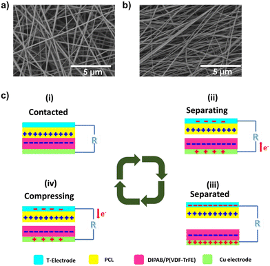 | ||
| Fig. 3 FESEM image of a prepared (a) neat P(VDF-TrFE) and (b) 5 wt% DIPAB/P(VDF-TrFE) fiber mat. (c) Working mechanism of the TENG device in contact-separation mode. | ||
Fig. 1 represents the TENG device schematically, whereas its operational mechanism is demonstrated in Fig. 3c. This device functioned in conventional contact separation mode, relying on contact electrification and electrostatic induction (Fig. S5†).33
Initially, both tribomaterials were not in direct contact. Hence, neither surface accumulated charges, thereby leading to an absence of electric potential difference between electrodes. As soon as an external force was applied, the upper PCL layer came into contact with the lower DIPAB/P(VDF-TrFE) layer, which generated equivalent charges with reverse polarities onto their surface. This phenomenon was due to the difference in electron affinities of PCL and DIPAB/P(VDF-TrFE) because PCL exhibits an oppositive triboelectric charge compared with that of DIPAB/P(VDF-TrFE) as stated by the triboelectric series.34,35 This phenomenon leads to the induction of positive and negative triboelectric charges onto the surfaces of PCL and DIPAB/P(VDF-TrFE), respectively. When the external force is liberated, the surfaces begin to separate, resulting in a net- generated triboelectric charge. This action leads to opposite charges onto the electrodes via electrostatic induction, creating a significant electric potential difference between them.
Consequently, electrons flow from the bottom electrode to the top electrode through the external circuit to equalize the potential difference, yielding a positive electrical output signal. Once the layers are fully separated, the electrical potential reaches an equilibrium, and a net current does not flow through the external circuit. If the force is exercised again, the re-established potential difference at the electrodes drives the electrons to flow back from the top electrode to the bottom electrode, generating an electrical output signal with the opposite polarity.
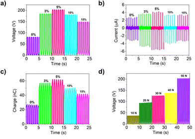
Eventually, the mechanical energy-harvesting capabilities of fabricated devices were assessed by subjecting them to cyclic contact and separation modes under an applied force of 50 N and a frequency of 1.3 Hz (Fig. 4). Performance data revealed that a device without any filler yielded an output voltage of only 80.7 V (Fig. 4a). However, with addition of just 3 wt% of the filler, an enhanced voltage of 185.2 was observed, which increased further to 203.8 V at 5 wt%. This value signified an almost 2.5-fold boost in performance. However, once this loading content (5 wt%) was reached, a declining trend in performance became evident. Similar variation trends were observed in the profiles of current and transferred charges, where increases of 1.57-fold and 2.3-fold were attained, respectively (Fig. 4b and c). The obtained performance closely aligns with recent reports on ferroelectric-based devices, underscoring their potential as a viable substitute for their inorganic counterparts (Table S1†). To account for the influence of areal mass density on output performance (Fig. S6†), we analyzed normalized triboelectric parameters (voltage/current/charge). This metric provides insights into the efficiency of voltage generation per unit mass of the active material in the TENG. As seen from Fig. S7,† a peak performance at 5 wt% suggested an optimal balance between charge generation and charge-collection efficiency due to factors such as increased surface area and fiber morphology. As the concentration increased beyond 5 wt%, factors such as jet instability (which leads to bead formation) became more prominent. These limitations outweigh the benefit of having more active materials, leading to a decrease in normalized triboelectric parameters. These data provide valuable insights into the optimization of TENG design and material selection for enhanced efficiency of energy harvesting.
The notable increase in output performance observed in polymer composites with an embedded ferroelectric filler could be attributed to the synergistic effect stemming from the ferroelectric filler and improved triboelectric properties. The dielectric constant is a vital factor guiding the performance of the TENG, particularly in terms of enhancing output efficiency.36 Therefore, boosting the dielectric constant of tribomaterials in the device could lead to improved performance. Fig. S8† illustrates the impact of DIPAB loading content on the dielectric characteristics of DIPAB/P(VDF-TrFE) composite films. Measurements were conducted under standard room conditions (296 K, relative humidity of 30%) across the frequency spectrum from 50 Hz to 1 MHz.
As the filler concentration in the nanofiber mat increased from 0% to 5 wt%, the dielectric constant exhibited a sequential increase from 2 to 4.3. Introduction of the DIPAB/P(VDF-TrFE) nanofiber mat led to a nearly 2.1-fold rise in the dielectric constant compared with that of the pure P(VDF-TrFE) mat. This phenomenon could be ascribed mainly to formation of a micro-capacitor structure. As demonstrated previously, the presence of interfaces in composite materials leads to Maxwell–Wagner–Sillars-type polarization.37 This polarization at the interface between the DIPAB particle and bulk P(VDF-TrFE) polymer results in substantial accumulation of charge near the interface and surface. This effect, in turn, facilitates greater flow of electrons through the circuit, contributing to enhanced performance. Similar to the dielectric constant, the dielectric loss also tended to increase with the incorporation of DIPAB fillers (Fig. S9†). A maximum dielectric loss of 0.037 was found for the 5 wt% DIPAB/P(VDF-TrFE) fiber mat. The high dielectric loss observed in the 5 wt% sample could be attributed to increased energy dissipation caused by additional polarization mechanisms introduced by the interfaces. All of the composites had dielectric loss in the range of 0.021–0.037, consistent with previous reports on P(VDF-TrFE).38,39
Further enhancement in the triboelectric output was identified due to the linked piezoelectricity of DIPAB/P(VDF-TrFE) films. A piezoelectric-active material experiences mechanical deformation from an applied strain, which gives rise to dipole generation.40 The alignment of these dipoles is intensified significantly by the presence of the triboelectric field, leading to amplification of dipolar polarization. This augmentation further facilitates the production of additional negative charges on the surface of the composite film during TENG operation.41
Surface roughness is a crucial factor that can modulate triboelectric properties.42 To investigate this feature, we acquired three-dimensional (3D) images of DIPAB/P(VDF-TrFE) membrane surfaces (Fig. S10†). The 5 wt% DIPAB/P(VDF-TrFE) film demonstrated a higher roughness value of 1.236 μm compared with that of the pristine polymer P(VDF-TrFE) film (1.032 μm). This difference implied that the inclusion of DIPAB particles and the reduced diameter of the fibers promoted roughness to a sizable extent, which is highly advantageous for triboelectrification.
The rise in output signals was linked to a certain extent, 5 wt% in this case, after which a gradual drop in performance was evidenced. The reason for this fall was attributed to the percolation theory.43 Excess loading of DIPAB leads to agglomeration, which disrupts the microcapacitor structure. Subsequently, this diminishes polarizability as a result of reduced interfacial polarization in the composite ferroelectric films, resulting in reduced outputs. These findings confirmed that the inclusion of DIPAB up to 5 wt% could enhance the output performance of TENG effectively.
The optimized 5 wt% device as a function of applied force was investigated comprehensively to check its potential application as a force sensor (Fig. 4d). It has been reported that the real contact area rises proportionally with an increase in the applied force.44 As displayed in Fig. 4d, the output voltage displayed an increase in performance with increasing force from 10 N to 50 N. A nearly 5.5-fold increase in the output voltage (from 37 V at 10 N to 203.8 V at 50 N) was achieved with only a fivefold increase in applied force. The linear relationship observed in the voltage suggests that the device could serve as a force sensor, which exhibited a sensitivity of 3.7 V N−1 (R2 = 0.95) (Fig. S11†).
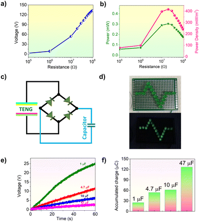
To assess the immediate power output of the most efficient 5 wt% device, we investigated the influence of external load resistance under a consistent force of 50 N and a set frequency of 1.3 Hz. As illustrated in Fig. 5a, while increasing the load resistance from 100 kΩ to 100 MΩ, the output voltage demonstrated an upward trend. Consequently, an optimal load of 20 MΩ led to a maximum power density of 416.2 mW m−2 (Fig. 5b). Furthermore, subjecting the device to a repetitive cycle of compression and release at an applied force of 50 N resulted in a consistent output without a notable decrease (Fig. S12†). This additional test confirmed the robustness of the device for prolonged and continuous operation.
The potential of these devices as a viable energy source for low-power electronics was established by direct harnessing of the power generated by the optimal 5 wt% device. The ensuing alternating-current signals were rectified via a full-wave bridge rectifier circuit (Fig. 5c). These electrical signals effectively illuminated a series of LEDs (Fig. 5d). Moreover, the generated power was utilized to charge various electrolytic capacitors. The charging profiles for all capacitors for 60 s are depicted in Fig. 5e. According to the charging profile, the output voltage exhibited a steady rise, which reached 25.2, 11.8, 6.7, and 2.9 V across the respective 1, 4.7, 10, and 47 μF capacitors. Fig. 5f and S13† provide visual representations of the accumulated charge and stored electrical energies in the capacitors, respectively.
One practical application for these devices in wearable electronics is capturing the mechanical energy present in common human movements. To explore this potential, we utilized the 5 wt% device to convert different human motions into electrical energy (Fig. 6). A simple one-finger tap produced a noticeable output voltage of 34.2 V. Activities such as jumping generated significantly higher outputs of 223.8 V due to the increased force, and increased frequency, which together generated an enhanced amplitude.
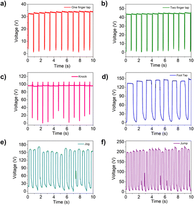 | ||
| Fig. 6 Harvesting of biomechanical energy using different human-body motions, including tapping of (a) one and (b) two fingers (c) knocking, (d) foot tapping, (e) jogging and (f) jumping. | ||
4 Conclusions
We described a novel approach involving a molecular ferroelectric-based electrospun composite film towards triboelectric-energy harvesting. The film was crafted meticulously by incorporating different percentages of DIPAB particles into P(VDF-TrFE) film and fed into an electrospinning method to generate fiber mats of high surface area. This strategy facilitated formation of an electroactive β-phase and resulted in enhanced dielectric properties due to ferroelectric particles, which enabled superior output performance. An optimal device comprising 5 wt% loading rendered the maximum power density of 416.2 mW m−2 at a threshold load of 20 MΩ. To further illustrate the efficacy of the mechanic–electric conversion, we utilised it to drive low-power electronics such as capacitors and LEDs, and validated its usefulness for generating power from everyday human-body motions. Considering the structural tunability that molecular ferroelectrics possess and effective modulation strategies that can be applied, our study unfolds a platform for exploring novel molecular ferroelectrics.Author contributions
SD: conceptualization, methodology, investigation, data curation, data analysis, validation, and writing (original draft). SA: data analysis, investigation, and writing (review and editing). NH: data analysis, validation, and writing (review and editing). WG: resources and writing (review and editing). BL and VM: lead supervision, conceptualization, resources, writing (review and editing), project administration, and funding acquisition.Conflicts of interest
There are no conflicts of interest to declare.Acknowledgements
This work was supported by NSF-ASSIST Center (EEC-1160483). This work was undertaken in part at the Analytical Instrumentation Facility (AIF) at North Carolina State University, which is supported by the State of North Carolina and the National Science Foundation (ECCS-2025064). This work made use of instrumentation at AIF acquired with support from the National Science Foundation (DMR-1726294). The AIF is a member of the North Carolina Research Triangle Nanotechnology Network, a site in the National Nanotechnology Coordinated Infrastructure.References
- S. Wang, J. Xu, W. Wang, G.-J. N. Wang, R. Rastak, F. Molina-Lopez, J. W. Chung, S. Niu, V. R. Feig, J. Lopez, T. Lei, S.-K. Kwon, Y. Kim, A. M. Foudeh, A. Ehrlich, A. Gasperini, Y. Yun, B. Murmann, J. B. H. Tok and Z. Bao, Nature, 2018, 555, 83–88 CrossRef CAS PubMed.
- J. Kim, A. S. Campbell, B. E.-F. de Ávila and J. Wang, Nat. Biotechnol., 2019, 37, 389–406 CrossRef CAS PubMed.
- J. Tu, R. M. Torrente-Rodríguez, M. Wang and W. Gao, Adv. Funct. Mater., 2020, 30, 1906713 CrossRef CAS.
- Y. Zhan, Y. Mei and L. Zheng, J. Mater. Chem. C, 2014, 2, 1220–1232 RSC.
- M. Xie, K. Hisano, M. Zhu, T. Toyoshi, M. Pan, S. Okada, O. Tsutsumi, S. Kawamura and C. Bowen, Adv. Mater. Technol., 2019, 4, 1800626 CrossRef.
- V. Padmanabhan Ramesh, Y. Sargolzaeiaval, T. Neumann, V. Misra, D. Vashaee, M. D. Dickey and M. C. Ozturk, npj Flexible Electron., 2021, 5, 5 CrossRef CAS.
- V. Misra, B. Lee, P. Manickam, M. Lim, S. K. Pasha, S. Mills and S. Bhansali, IEEE Int. Electron Devices Meet., 2015, 13.1.1–13.1.4 Search PubMed.
- V. Misra, A. Bozkurt, B. Calhoun, T. Jackson, J. S. Jur, J. Lach, B. Lee, J. Muth, O. Ö. M. Öztürk, S. Trolier-McKinstry, D. Vashaee, D. Wentzloff and Y. Zhu, Proc. IEEE, 2015, 103, 665–681 CAS.
- O. Oralkan, S. Bhansali, A. Bozkurt, M. D. Dickey, B. Lee, T. Mayer, V. Misra, J.-H. Moon, J. F. Muth, O. D. Velev and Y. Zhu, ECS Meet. Abstr., 2014, MA2014-01, 454 CrossRef.
- S. Deswal, R. Panday, D. R. Naphade, P. A. Cazade, S. Guerin, J. K. Zaręba, A. Steiner, S. Ogale, T. D. Anthopoulos and R. Boomishankar, Small, 2023, 2300792 CrossRef CAS PubMed.
- S. Deswal, G. Khandelwal and R. Dahiya, IEEE Sens. Lett., 2023, 7, 1–4 Search PubMed.
- Y. C. Lai, H. W. Lu, H. M. Wu, D. Zhang, J. Yang, J. Ma, M. Shamsi, V. Vallem and M. D. Dickey, Adv. Energy Mater., 2021, 11, 2100411 CrossRef CAS.
- Y. Zhang, P. T. T. Phuong, E. Roake, H. Khanbareh, Y. Wang, S. Dunn and C. Bowen, Joule, 2020, 4, 301–309 CrossRef CAS.
- C. Wu, A. C. Wang, W. Ding, H. Guo and Z. L. Wang, Adv. Energy Mater., 2019, 9, 1802906 CrossRef.
- G. Khandelwal, S. Deswal and R. Dahiya, ACS Omega, 2022, 7, 44573–44590 CrossRef CAS PubMed.
- H. Dan, H. Li and Y. Yang, Front. Mater., 2022, 9, 939173 CrossRef.
- W. Seung, H. J. Yoon, T. Y. Kim, H. Ryu, J. Kim, J. H. Lee, J. H. Lee, S. Kim, Y. K. Park and Y. J. Park, Adv. Energy Mater., 2017, 7, 1600988 CrossRef.
- L. Li, X. Wang, Y. Hu, Z. Li, C. Wang and Z. Zhao, Adv. Funct. Mater., 2022, 32, 2109949 CrossRef CAS.
- Y.-E. Shin, S.-D. Sohn, H. Han, Y. Park, H.-J. Shin and H. Ko, Nano Energy, 2020, 72, 104671 CrossRef CAS.
- Y. E. Shin, Y. J. Park, S. K. Ghosh, Y. Lee, J. Park and H. Ko, Adv. Sci., 2022, 9, 2105423 CrossRef CAS PubMed.
- J.-H. Zhang, Y. Zhang, N. Sun, Y. Li, J. Du, L. Zhu and X. Hao, Nano Energy, 2021, 84, 105892 CrossRef CAS.
- H. Fang, Q. Li, W. He, J. Li, Q. Xue, C. Xu, L. Zhang, T. Ren, G. Dong and H. Chan, Nanoscale, 2015, 7, 17306–17311 RSC.
- G. Min, A. Pullanchiyodan, A. S. Dahiya, E. S. Hosseini, Y. Xu, D. M. Mulvihill and R. Dahiya, Nano Energy, 2021, 90, 106600 CrossRef CAS.
- H.-Y. Liu, H.-Y. Zhang, X.-G. Chen and R.-G. Xiong, J. Am. Chem. Soc., 2020, 142, 15205–15218 CrossRef CAS PubMed.
- D.-W. Fu, H.-L. Cai, Y. Liu, Q. Ye, W. Zhang, Y. Zhang, X.-Y. Chen, G. Giovannetti, M. Capone, J. Li and R.-G. Xiong, Science, 2013, 339, 425–428 CrossRef CAS PubMed.
- R. Zhang and H. Olin, EcoMat, 2020, 2, e12062 CrossRef CAS.
- A. Chen, C. Zhang, G. Zhu and Z. L. Wang, Adv. Sci., 2020, 7, 2000186 CrossRef CAS PubMed.
- Y. Zou, J. Xu, K. Chen and J. Chen, Adv. Mater. Technol., 2021, 6, 2000916 CrossRef CAS.
- L. Wu, P. Xue, S. Fang, M. Gao, X. Yan, H. Jiang, Y. Liu, H. Wang, H. Liu and B. Cheng, Mater. Horiz., 2024, 11, 341–362 RSC.
- Y.-Z. Liu, Q. Zhang, X.-X. Wang, Y. Lu, W.-B. Li, Q.-Y. Peng and F.-Y. Xu, ACS Appl. Nano Mater., 2024, 7, 4630–4652 CrossRef CAS.
- X. Hu, X. Yan, L. Gong, F. Wang, Y. Xu, L. Feng, D. Zhang and Y. Jiang, ACS Appl. Mater. Interfaces, 2019, 11, 7379–7386 CrossRef CAS PubMed.
- A. Sultana, M. M. Alam, P. Sadhukhan, U. K. Ghorai, S. Das, T. R. Middya and D. Mandal, Nano Energy, 2018, 49, 380–392 CrossRef CAS.
- Z. L. Wang, L. Lin, J. Chen, S. Niu, Y. Zi, Z. L. Wang, L. Lin, J. Chen, S. Niu and Y. Zi, Triboelectr. Nanogener., 2016, 23–47 Search PubMed.
- C. Fan, J. Huang, A. Mensah, Z. Long, J. Sun and Q. Wei, Cell Rep. Phys. Sci., 2022, 3, 101012 CrossRef CAS.
- N. Luo, Y. Feng, D. Wang, Y. Zheng, Q. Ye, F. Zhou and W. Liu, ACS Appl. Mater. Interfaces, 2020, 12, 30390–30398 CrossRef CAS PubMed.
- L. Jin, X. Xiao, W. Deng, A. Nashalian, D. He, V. Raveendran, C. Yan, H. Su, X. Chu and T. Yang, Nano Lett., 2020, 20, 6404–6411 CrossRef CAS PubMed.
- H. Hammami, M. Arous, M. Lagache and A. Kallel, J. Alloys Compd., 2007, 430, 1–8 CrossRef CAS.
- S. M. S. Rana, M. T. Rahman, M. Salauddin, S. Sharma, P. Maharjan, T. Bhatta, H. Cho, C. Park and J. Y. Park, ACS Appl. Mater. Interfaces, 2021, 13, 4955–4967 CrossRef CAS PubMed.
- S. M. S. Rana, M. T. Rahman, M. Salauddin, S. Sharma, P. Maharjan, T. Bhatta, H. Cho, C. Park and J. Y. Park, ACS Appl. Mater. Interfaces, 2021, 13, 4955–4967 CrossRef CAS PubMed.
- S. Deswal, R. Panday, D. R. Naphade, P. Dixit, B. Praveenkumar, J. K. Zaręba, T. D. Anthopoulos, S. Ogale and R. Boomishankar, Chem. – Eur. J., 2022, 28, e202200751 CrossRef CAS PubMed.
- S. Ippili, V. Jella, A. M. Thomas, C. Yoon, J.-S. Jung and S.-G. Yoon, J. Mater. Chem. A, 2021, 9, 15993–16005 RSC.
- N. Sun, X.-N. Zhang, J.-Z. Li, Y.-W. Cai, Z. Wei, L. Ding and G.-G. Wang, ACS Sustainable Chem. Eng., 2023, 11, 5608–5616 CrossRef CAS.
- E. J. W. Essam, Rep. Prog. Phys., 1980, 43, 833 CrossRef.
- G. Min, Y. Xu, P. Cochran, N. Gadegaard, D. M. Mulvihill and R. Dahiya, Nano Energy, 2021, 83, 105829 CrossRef CAS.
Footnote |
| † Electronic supplementary information (ESI) available. See DOI: https://doi.org/10.1039/d4lp00024b |
| This journal is © The Royal Society of Chemistry 2024 |

