A review of hierarchical porous carbon derived from various 3D printing techniques
Cameron
Romero†
,
Zhi
Liu†
,
Zhen
Wei
and
Ling
Fei
 *
*
Department of Chemical Engineering, University of Louisiana at Lafayette, USA. E-mail: ling.fei@louisiana.edu
First published on 21st May 2024
Abstract
Hierarchical porous carbon is an area of advanced materials that plays a pivotal role in meeting the increasing demands across various industry sectors including catalysis, adsorption, and energy storage and conversion. Additive manufacturing is a promising technique to synthesize architectured porous carbon with exceptional design flexibility, guided by computer-aided precision. This review paper aims to provide an overview of porous carbon derived from various additive manufacturing techniques, including material extrusion, vat polymerization, and powder bed fusion. The respective advantages and limitations of these techniques will be examined. Some exemplary work on various applications will be showcased. Furthermore, perspectives on future research directions, opportunities, and challenges of additive manufacturing for porous carbon will also be offered.
1. Introduction
Porous carbon materials have emerged as promising candidates in sectors such as water purification,1 gas adsorption/separation,2 catalyst supports,3 and energy storage and conversion amongst many others.4–6 This prominence is due to their many distinct properties and advantages, setting them apart from other materials. Firstly, they have a high specific surface area that can increase the number of active sites present, fostering an improved interaction with targeted molecules. Additionally, the pores in the material can be tailored, encompassing aspects such as pore size distribution and volume, which increases its performance for specific applications.7–9 In general, these porous carbon materials are categorized based on their pore size with the smallest being microporous (pore size < 2 nm), followed by mesoporous (2 nm ≤ pore size ≤ 50 nm), and finally macroporous (pore size > 50 nm).10 Additionally, certain types of carbons exhibit excellent electrical conductivity, making them applicable in areas like energy conversion and storage.11 Lastly, the exceptional chemical stability of porous carbons ensures resilience against degradation/corrosion in severe environments, providing reliability in a wide array of applications.12One of the most common approaches for synthesizing porous carbon is physical activation, where carbon precursors are heated in the presence of activating agents such as steam or CO2, forming pores within the carbon structure.13 Chemical activation is another method which employs agents like KOH that interact with precursors to produce controlled pores during heating.14 The primary difference in chemical and physical activation is that in chemical activation, the precursor is impregnated with the agent and then heated as opposed to the agent simply being in the presence of the precursor. Additionally, pyrolysis of porous precursors has been widely performed to produce porous carbon, including metal–organic frameworks (MOFs), at high temperatures to produce well-controlled, unique, porous structures. Alternatively, materials like porous SiO2 can be used as a template, impregnating the carbon precursor and pyrolyzing it, subsequently removing the SiO2 to leave behind a porous carbon framework.15 Moreover, natural materials like wood possess a unique heterogeneous biostructure, contributing significantly to the microstructure development during the synthesis steps. These materials also serve as excellent renewable sources for porous carbon.16 Most of the synthesis methodologies mentioned above generally result in powdered forms of porous carbon. While these methods allow precise control at the microscopic level for individual carbon particles, they often provide limited control over the macroscopic architecture of the entire materials, such as electrodes, when it comes to practical applications.
The macroscopic architecture has been proved equally crucial for optimizing the performance.17,18 Take supercapacitors as an example, where porous carbon is extensively employed. The synthesized powder must be transformed into electrodes. Currently, the slurry coating method lacks precise control over the macroscopic architecture of the electrodes.19,20 Specifically, porous carbon particles are distributed randomly on a statistical basis. Achieving control at both the individual particle level (micro/meso pores) and the macroscopic structure of the final electrodes would represent a significant advancement.
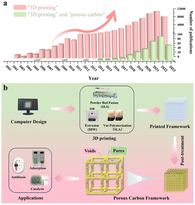
Three-dimensional (3D) printing, also known as additive manufacturing, offers an efficient, cost-effective, and consistent approach for producing architectured porous carbon by simplifying the production procedure for layered manufacturing.21 This class of techniques can provide precise control over the thickness, porosity, rigidity, and geometrical shape of the material from both a microscopic and a macroscopic point of view.22 To date, numerous excellent review articles are available on the synthesis of porous carbon in powder form, covering various carbon classifications and applications.23–27 Additionally, review articles focusing on the advancements in 3D printing are also available.28–32 Notably, Blyweert et al. reviewed advances in 3D carbon printing and provided insight into functional carbon-based systems. They discuss carbon systems in general rather than with the sole focus on porous carbon. Thereby, this work serves as a complementary resource for the unique properties and opportunities of porous carbon materials by 3D printing, which is critical for further advancing their practical applications in various fields.33 With this in mind, there is a lack of reviews on porous carbon derived from various 3D printing techniques. The related statistics for publications over the past few decades collected from Web of Science by inputting the keywords “3D printing” and “porous carbon” are presented in Fig. 1a, showcasing the escalating trend in studies on 3D printing technology and its combination with porous carbon materials. Therefore, it would be greatly beneficial to have such a summary and discussion on porous carbon derived from diverse 3D printing techniques. This review aims to bridge this gap by initially offering an overview of advanced 3D printing methods. Then, it is followed by a brief showcase and discussion of exemplary porous carbon prepared by each printing method. Finally, some perspectives and directions on advancements in 3D printing to produce porous carbon will be discussed. It's important to note that we distinguish between a void and a pore for simplification in this review. To be clear, a void represents an empty space within a computer-designed structure, while a pore indicates an opening within the material itself, which is summarized in Fig. 1b.
2. 3D printing overview
A variety of 3D printing techniques have been developed to cater to specific applications. In 2015, the American Society of Testing and Materials (ASTM) catalogued 3D printing technologies into seven main groups based on technical features: Material Extrusion, Vat Polymerization, Powder Bed Fusion, Material Jetting, Binder Jetting, Direct Energy Deposition and Sheet Lamination.34 One of the technical features analyzed was the material used. Since the production of porous carbon requires carbon precursors, only the techniques that utilized plastics/resins will be analyzed. As a result, this section provides an overview and comparison of Material Extrusion, Vat Polymerization, and Powder Bed Fusion with the aim of discussing operational principles, advantages, limitations, and suitability. All the information listed within this section is summarized in Table 1.35–43| Printing method | Resolution (plane x–y) | Scalability (based on supply chain) | Multi-material compatibility | Cost (based on small batches) | Post-treatment | Advantages | Disadvantages | Ref. |
|---|---|---|---|---|---|---|---|---|
| Material extrusion | Medium (1–100 μm) | Fair | Good (polymers with rheological properties) | Low (inexpensive equipment and materials with abundant elections) | Required | Good multi-materials ability; low cost in small-scale printing | Low build speed; post-curing | 32, 35, 38–39 and 41 |
| Vat polymerization | High (>600 nm) | Poor | Poor (photo-curable polymers with low viscosity) | Medium (cheap equipment, but relatively high-cost starting materials) | Required | High resolution; complex structures with fine features are printable | Supports needed; limitation of printing composite with high content; post-curing | 32, 36, 40 and 43 |
| Powder bed fusion | Low (>100 μm) | Good | Poor (thermoplastic polymer powder) | High (high-cost materials and relatively expensive equipment) | Not required | Super high build speed; support-free | Low resolution; high processing temperature; high machine and material cost for starters | 32, 37, 40 and 42 |
2.1 Material extrusion
Material extrusion, often referred to as Fused Deposition Modeling (FDM), is a 3D printing method that uses ink or filaments fed through a heated nozzle. The filament is heated to just above its melting point, forming a molten material that is deposited onto a print bed by moving the nozzle along the x, y, and z axes to form the desired object. Once deposited, the material is rapidly solidified to produce a strong and durable final product. This basic working principle of material extrusion can be seen in Fig. 2.44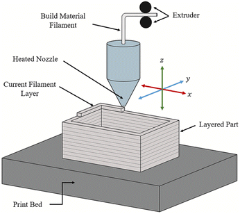 | ||
| Fig. 2 The basic working principle of material extrusion printing.44 | ||
One of the main advantages of material extrusion lies in its adaptability to a wide range of materials.45 Researchers can select from a diverse array of thermoplastic filaments, each with unique properties and characteristics. This allows for the production of components with tailored attributes, making it a versatile tool in various industries.46 Moreover, the presence of various nozzle diameters and layer thicknesses provides further flexibility in the design and fabrication processes.47 This allows the user to fine-tune their builds to precise specifications. Alongside its material adaptability, material extrusion excels in cost-effectiveness as FDM printers are notably more budget friendly, expanding its accessibility to a wider spectrum of researchers and institutions. Lastly, the straightforwardness of the process streamlines operation and upkeep, making it an accessible choice for projects of varying sizes and complexities.48
While material extrusion offers significant advantages, it does come with a set of limitations. Most notably, this process is less suitable for producing intricate parts due to the circular profile of the print nozzle, resulting in a layer thickness equal to the diameter of the nozzle. These visible layers often result in a stair-stepped effect and require post processing to achieve a smooth surface, which takes time and can get messy.49 Furthermore, the bond and strength of the printed part are usually weakest along the plane of the layer interface, resulting in compromised rigidity. Moreover, since the printed builds are coming out of the tip of the nozzle, any scale up will take more time in a linear fashion.50 Finally, certain filaments may experience degradation or undesirable phase transitions during the high-temperature printing process, necessitating a careful consideration of the printing parameters for successful outcomes.51
2.2 Vat polymerization
Vat polymerization is a family of 3D printing techniques that uses a build platform, ultraviolet light, and a vat of photopolymer resin to produce three-dimensional objects. The build platform is submerged in the resin and the light is shon in a pre-coded manner to cure the resin layer-by-layer. As each layer is solidified, the build platform is moved further from the light source (typically in intervals between 10 and 50 μm) to allow more resin to infill and cure. The light source can be applied to either the bottom or top of the printer and is dictated by the fluid properties of the resin. A schematic of both orientations of the layer-based vat photopolymerization printing process can be seen in Fig. 3.52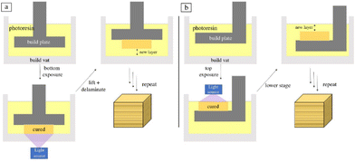 | ||
| Fig. 3 Schematic of layer-based vat photopolymerization where the light is oriented from (a) the bottom and (b) the top.52 | ||
The most attractive feature of vat polymerization printing is the use of ultraviolet light that allows for the production of intricate, highly detailed parts with an extreme level of accuracy and resolution.53 Consequently, the cured resin tends to exhibit smooth surface finishes, thereby reducing the need for extensive post-processing steps.54 Additionally, this method offers a broad spectrum of material options, encompassing specialized resins with varying properties such as flexibility, transparency, and biocompatibility. The remarkable versatility in material selection highlights the adaptability to cater to specific research or application needs, facilitating the production of components with a wide range of properties, spanning from rigid and durable to flexible and elastomeric.55 Lastly, upscaling does not add additional time since the print duration is solely a function of the height of the build(s), rather than the volume consumed.56
The drawback of vat polymerization is the restrictions on the build size. Both the size of the 3D printer and the volume of resin vat impose constraints on the maximum dimensions of the printed object, limiting its suitability for large-scale prints.57 Additionally, the process can be sensitive to ambient conditions, particularly temperature, humidity, and luminosity, which can influence the curing process and affect the final print quality.58 Another factor to consider is the cost associated with specialized photopolymer resins, which can be relatively expensive.59 Finally, due to the intricate detailing and the build platform moving along the gravity axis, supports are often required to prevent the object from deforming.56
2.3 Powder bed fusion
Powder bed fusion is a printing method that uses an energy source (e.g., thermal energy and laser) to selectively melt and fuse together fine powder particles. It is composed of two main compartments: a powder reservoir and a build platform. To begin, the reservoir is filled with round and smooth powder that is heated to just under its melting point. A powder spreader, usually a roller or a blade, is then used to distribute a thin, uniform layer of powder on the build plate. A high-powered laser then selectively heats up the regions of the powder, fusing together the particles. The build platform is then lowered while the powder reservoir is raised, and the process is repeated until the final product is formed. A schematic of powder bed fusion can be found in Fig. 4.60 | ||
| Fig. 4 Schematic of powder bed fusion.60 | ||
One of the biggest advantages of powder bed fusion compared to other 3D printing techniques lies in its ability to produce complex, fully functional internal structures with fine details. This is achieved by utilizing unfused powder as a support, granting an unprecedented level of geometric freedom. Unlike traditional methods, not every part of the component needs to be connected during the printing process, allowing for unparalleled design complexity and functionality.61 Additionally, the printing method allows for tight adhesion between its layers with minimal waste. Furthermore, scale-up is viable since the most time-consuming step is spreading a new layer of powder.60,62
While powder bed fusion boasts impressive advantages, it is important to consider some of its drawbacks. For starters, the equipment is relatively expensive, making it less accessible.63 Additionally, the post-processing stage presents its own set of complexities. Each printed part must be carefully extracted from the powder bed and thoroughly cleaned, a task that becomes more intricate and time-consuming as the size of the print gets smaller. There are integrated powder removal systems that can de-powder parts and recycle unused powder, but these systems are expensive and are still in the developmental phase.64 Finally, the use of high-powered lasers in the process demands strict adherence to safety protocols to mitigate any potential hazards.65
3. Porous carbon from 3D printing
Each category of 3D printing has subcategories with unique advantages, limitations, and applications tailored to a targeted process. Since the demand for 3D printing continues to grow, these subcategories are constantly being developed and refined. While the previous section provided an overview of the general mechanisms and pros and cons of each additive manufacturing technique that utilizes plastics/resins, the next section will focus specifically on the subcategories that have been used to produce porous carbon.3.1 Porous carbon derived from material extrusion
The most common material extrusion method that utilizes carbon-based ink is direct ink writing, more commonly referred to as DIW. The ink for this method is typically composed of functional fillers, binders, solvents, and additives.66 In regard to porous carbon, the functional filler would be a carbon precursor, which would change depending on the intended purpose. The binders help to uniformly disperse the ink within the syringe. The binder must be compatible with the functional filler, provide good adhesion, and, in most cases, allow for easy removal after printing to increase the density of functional fillers. The solvent is used to modify the viscosity to affect the dispensation and drying rate. Finally, additives can be implemented to enhance the final characteristics.67The versatility of components within the DIW printing method makes it attractive for many applications. For instance, Liu et al. were able to manufacture a monolithic nitrogen-doped porous carbon material via the DIW method for the removal of methylene blue (MB). The ink consisted of starch and gelatin as the carbon source, melamine as the nitrogen additive, water as the solvent, and silicon dioxide as the filler and template. The mixture was printed, carbonized, and then treated with NaOH and HNO3 to produce the meso/macro nitrogen-doped porous carbon (Fig. 5), which allowed for the easy adsorption of MB without the need for centrifugation, filtration, or magnetic separation. The microscopic pore structure size and specific surface area of the material could be controlled by adjusting the size of the SiO2 templates.68 The results proved that the DIW-printed porous carbon materials are promising in the realm of adsorption and catalysis.
 | ||
| Fig. 5 Schematic illustration of the DIW process to produce porous carbon.68 | ||
More recently, Zhou et al. utilized the DIW method for printing a catalyst for the oxidation of benzyl alcohol. To do this, SiO2 spheres with different diameters were prepared via the Stöber method. The ink was a mixture of starch, gelatin, and SiO2 spheres. After printing, carbonization, and treatment with NaOH and HNO3, they found that the smaller SiO2 spheres led to better oxidation of benzyl alcohol due to the increased surface area of the porous carbon (Fig. 6). This simple, low cost, and reliable method proved to hold great promise for further catalytic applications.69
 | ||
| Fig. 6 SEM of the printed carbon replicas with different SiO2 diameters: (a) 50 nm; (b) 100 nm; (c) 200 nm; and (d) 350 nm.69 | ||
In other works, Yang et al. prepared a 3D nitrogen-doped porous carbon aerogel by DIW printing and subsequent freeze-drying and pyrolysis. The ink consisted of agarose, urea, sodium chloride, and hydroxypropyl methylcellulose (Fig. 7). The obtained structure exhibited multiple desirable properties, including self-supportability, hierarchical porous structure, and good structural stability, allowing for use in home-built water flow-through devices for continuous treatment of Escherichia coli (E. coli) cultures. It led to 100% inactivation of bacteria for at least 5 hours, which far exceeds the capabilities of traditional catalysts.70
 | ||
| Fig. 7 Schematic for the fabrication of 3D nitrogen-doped porous carbon by DIW and the resulting morphology.70 | ||
Yao et al.71 fabricated a 3D-printed multiscale porous carbon aerogel (3D-MCA) using a unique blend of chemical methods and the direct ink writing technique. Micropores significantly increase the specific surface area of the electrode, while the macro- and mesopores serve as electrolyte reservoirs, drastically shortening the ion diffusion length during rapid charging. The 3D-MCA boasts an open porous structure and an impressive surface area of approximately 1750 m2 g−1. Remarkably, the symmetric device achieves a stunning capacitance of 148.6 F g−1 at a rate of 5 mV s−1, even at a chilling temperature of −70 °C. Moreover, it retains an impressive capacitance of 71.4 F g−1 at an accelerated scan rate of 200 mV s−1, which is 6.5 times higher than that of its non-3D printed MCA counterpart. These outstanding results rank among the top performances reported for low-temperature supercapacitors, highlighting the critical role of open porous structures in sustaining capacitive performance at ultralow temperatures.
Li et al.72 proposed a reduced graphene oxide (rGO)/Super-P aerogel composite electrode with a controllable porous structure, leveraging the innovative technique of direct ink writing (DIW). The DIW technique allows for precise control over both the macroscale and microscale porous structure of graphene aerogel. This control is facilitated by varying the printing path and the concentration of GO. The meticulously designed porous architecture provides an increased specific surface area for the reaction, reduces the mass transfer path, and enhances ion accessibility. These attributes contribute to a decrease in electrochemical polarization and an improvement in the accessibility of reactive ions. Moreover, the 3D-printed graphene aerogel boasts advantages such as low density, high porosity, superior mechanical properties, large specific surface area, and unique electrochemical properties. The cell equipped with the optimized rGO/Super-P aerogel electrode demonstrates a superior discharge capacity of 848.4 mA h at a current density of 80 mA cm−2. This performance represents a noteworthy 14.9% enhancement compared to a cell equipped with the traditional graphite felt (GF), underscoring the potential of a 3D printing approach in VRFB applications.
Aerosol jet printing (AJP), a novel non-contact direct writing technique, is specifically designed to achieve precise and intricate patterns on a variety of substrates.73 Parate et al.74 reported on an innovative aerosol-jet-printed (AJP) graphene-based immunosensor, which is capable of monitoring two distinct cytokines: interferon gamma (IFN-γ) and interleukin 10 (IL-10). To construct this sophisticated device, interdigitated electrodes (IDEs) were printed with a 40 μm finger width using graphene-nitrocellulose ink on a durable polyimide substrate. The IDEs were then subjected to an annealing process in CO2, a critical step that introduces reactive oxygen species onto the graphene surface. These oxygen species function as chemical handles, providing bonding sites to covalently attach IFN-γ and IL-10 antibodies to the graphene surfaces, thereby enhancing sensitivity. The resultant AJP electrochemical immunosensors exhibit a wide sensing range (IFN-γ: 0.1–5 ng mL−1; IL-10: 0.1–2 ng mL−1), a remarkably low detection limit (IFN-γ: 25 pg ml−1 and IL-10: 46 pg ml−1), and, most importantly, high selectivity, with the antibodies demonstrating minimal cross-reactivity with each other or IL-6.
In general, the process of utilizing material extrusion to produce porous carbon has been popularly applied to catalytic, adsorption, and absorption processes. This is because these processes primarily rely on the surface properties of the printed material, not their geometries. As a result, the simplicity and cost-effectiveness of material extrusion, along with its ability to generate porous carbon structures, makes it an invaluable tool in these applications despite low-resolution prints. Ongoing research and development in this field continue to address its limitations (layer–layer interface weakness,75 post-processing requirements,76 limited resolution,77 and limits on high-temperature materials78). Solutions to these issues will expand the potential applications of material extrusion and increase its effectiveness.
3.2 Porous carbon derived from vat polymerization
Stereolithography (SLA) is a promising vat polymerization technique for producing porous carbon. The resin is composed of photoinitiators, liquid monomers, and oligomers. These components are cross-linked in a layer-by-layer fashion by selectively photopolymerizing portions of the resin by means of a rastering laser. This method results in a high resolution (≥10 μm), making it possible to derive porous carbon structures with intricate details.52Steldinger et al. obtained hierarchical structured porous carbons from stereolithography and copolymerization of pentaerythritol tetraacrylate and divinylbenzene. The photocurable resin (35% pentaerythitol tetraacrylate, 35% divinylbenzene, and 30% bis(2-ethylhexyl) phthalate) was printed and treated to produce carbon with excellent mechanical strength as well as a high surface area (2200 m2 g−1) through activation.79 The entire process can be seen in Fig. 8. This study showed the ability of SLA to combine fast printing to produce porous carbon with high mechanical strength, making it excellent for porous carbon applications that require a robust nature.
 | ||
| Fig. 8 Schematic overview of the SLA printing process to produce porous carbon.79 | ||
Wang et al. developed a novel hybrid manufacturing method for fabricating 3D hierarchical porous carbon electrodes for electrochemical energy storage. This approach utilized SLA 3D printing with KOH chemical activation to produce macro, meso, and microporous carbon (Fig. 9). In order to tune the pore size, different ratios of KOH to the carbon material were employed and studied, which showed that an increase in KOH will decrease the pore size and result in better electrochemical results. This correlation is ascribed to the fact that an ideal porous carbon electrode must allow for fast mass diffusion routes for the ions as well as providing rapid electron transfer pathways.80 Since SLA 3D printing not only produces porous carbon but does so in a controllable way for architectured electrode design with a high resolution, this makes it highly applicable in electrochemical energy storage and conversion applications, particularly when a complex electrode structure is required.
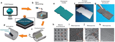 | ||
| Fig. 9 Schematic of the SLA print process and SEM/TEM imaging of macroarchitectures, macropores, mesopores, and micropores with scale bars of 1 mm, 20 μm, 100 nm, and 5 nm, respectively.80 | ||
Blyweert et al. demonstrated for the first time an effective strategy to develop a 3D-printed carbon material from bio-based resins using stereolithography.33 Traditional resins are made based on petrochemical origins, which often have a low carbon yield and undergo significant volume shrinkage (50–90%) after pyrolysis. To address this, the group added condensed tannin (a wood extract) to the resin, and printed, post-cured, and pyrolyzed the component to produce a porous carbon lattice. The results yielded about 20% carbon content with a reduced warpage and volume shrinkage of approximately 35%, a significant increase compared to traditional neat resins. This work shows the potential of obtaining a sustainable, highly porous carbon build with complex architectures.
Jiang et al. fabricated a novel porous carbon model embedded with bismuth-based particles by the SLA method and following calcination in air at low temperature, as the light-enhanced removal agent of chloride (Cl−) in wastewater.81 The preparation conditions were optimized to obtain a BET surface area of 40 m2 g−1 with a more robust structure. The increase in the structure strength was primarily due to the optimization of the calcination temperature, which ensures sufficient carbonization while still maintaining the shape of the model. The porous structure allows more active materials to adhere on the surface and achieves better performance on the removal of Cl−. The resulting removal efficiency reaches 26% under the acidic and dark conditions, whereas it can be largely improved to 63.6% by irradiation of UV light. It is notable that this Bi-based porous carbon model can be regenerated by treatment with NaOH after every removal cycle and reused for the next cycle, which efficiently reduces the cost of materials and benefits sustainability. This work provides a promising way to alleviate the pollution of Cl− in water and expands the application field of SLA technology.
More recently, Katsuyama et al. were able to utilize SLA combined with CO2 gas activation to fabricate controlled macro- and nanoporous carbon lattices for use as electrodes in supercapacitors.82 The schematic of the whole synthetic route is clearly shown in Fig. 10. Then they deposited MnO2 onto the surface, which further enhanced the capacitance by a factor of 2.5 times. The achieved values are better than the materials prepared by almost all other manufacturing methods to date in terms of areal energy and power densities. The findings confirm that maintaining the macrostructure while simultaneously keeping an ordered microstructure can dramatically increase the power and energy output of a system owing to its ability to facilitate ion/electron transport within the material.
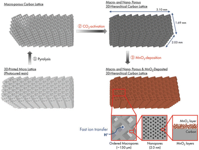 | ||
| Fig. 10 Schematic of the process for the preparation of a 3D-printed hierarchical porous carbon lattice with MnO2 deposition.82 | ||
Based on these findings, Kudo et al. coupled SLA with a hard template technique to achieve a hierarchical porous carbon microlattice with mechanical robustness and a high surface area with mitigated volume shrinkage (Fig. 11).83 The work developed a composite photoresin consisting of magnesium oxide nanoparticles as a porogen template blended with graphene nanosheets to reduce UV scattering and contribute to the formation of micro/macropores. The printed material had a considerable compressive strength and Young's modulus with a gravimetric capacitance upwards of 105 F g−1. This study shows that customizing the resin can allow for additives to be added prior to printing, highlighting that the prints can have a uniquely integrated structure with improved functional properties.
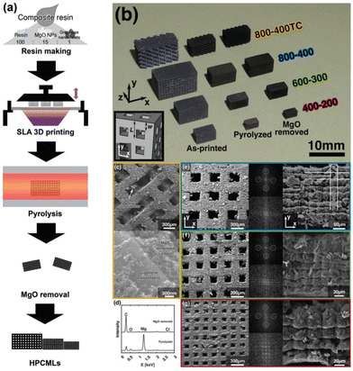 | ||
| Fig. 11 (a) Schematic process for the preparation of a hierarchical porous carbon microlattice by SLA; (b) an optical image of four types of samples at each step of preparation: as-printed, pyrolyzed, and MgO removed; (c) SEM images of sample 800–400TC with different magnifications; (e–g) SEM images with different magnifications and FFT patterns of the other three types of samples.83 | ||
Heijden et al.84 employed stereolithography 3D printing to manufacture model grid structures, which were then subjected to carbonization and evaluated as flow battery electrode materials. Porous electrodes play a crucial role in governing the electrochemical performance and pumping requirements in RFBs. However, conventional porous electrodes (e.g., carbon fiber based) have not been optimized to meet the specific requirements of liquid-phase electrochemistry. It is observed that the printing direction influences the electrode performance through a change in morphology, with diagonally printed electrodes exhibiting enhanced performance. Furthermore, mass transfer rates within the electrode are improved by helical or triangular pillar shapes, or using interdigitated flow field designs. This study showcases the potential of stereolithography 3D printing to fabricate customized electrode scaffolds. This technology could facilitate the development of multiscale structures with superior electrochemical performance and reduced pumping losses, offering new avenues for electrode optimization in RFBs.
Chandrasekaran et al.85 employed two advanced 3D printing methods – projection microstereolithography (PμSL) and two-photon polymerization direct laser writing (2PP-DLW) – for fabricating 3D sacrificial polymeric templates. These templates can range in size from a millimeter to a centimeter scale and feature intricate designs with details as small as tens of microns (PμSL) or even as minuscule as 100s of nanometers (2PP-DLW). The fabrication process of templated carbon aerogels (t-CAs) involves infiltrating the 3D-printed templates with resorcinol-formaldehyde (RF) precursor solution, followed by a high-temperature carbonization process at 1050 °C. During this stage, the RF precursor solution is converted into a CA while the 3D-printed template is simultaneously decomposed, leaving behind an intricate templated macroporous network structure. The presence of this templated macroporous architecture enhances mass transport within the t-CAs in comparison with traditional bulk CA. This improvement is clearly demonstrated through more uniform activation and the superior response of t-CAs in electrochemical cyclic voltammetry and galvanostatic charge–discharge tests.
Employing vat polymerization technology for the fabrication of porous carbon materials marks a significant stride towards materials science and engineering. The precision and versatility offered by vat polymerization enables the production of intricate and customizable porous structures with accuracy and reproducibility, making it useful for various applications such as energy storage where architectured electrodes are desired.86 Since UV light is the primary driving force to solidify the photocurable resin, additives can be implemented without thermal degradation, thus enhancing the feasibility of composite materials.87 However, the amount of additives that can be added to the resin to form a composite is constrained. This limitation arises as the additive particles start to scatter or absorb UV light, thereby restricting the crosslinking process. As for the future of vat polymerization, improvements in resin chemistry,88 UV laser characteristics, and printing parameters56 will result in higher resolution prints, making its applications even broader, enhancing its effectiveness, and increasing the percent of additives within the resin.
3.3 Porous carbon derived from powder bed fusion
Selective laser sintering (SLS), one of the oldest additive manufacturing techniques, is the most promising class of powder bed fusion to produce porous carbon.89 This process involves fusing carbon-rich precursors by heating a stock to a temperature directly lower than its melting point. Then, a rapid laser scans the surface, momentarily melting the precursor. The precursor immediately cools once the laser ceases, fusing the particles together in a stacking mechanism.90 This being said, not all materials are suitable for SLS. The material must be in powder form and have the ability to sinter under the influence of a laser, and the powder needs to have a consistent particle size. With this, limited amounts of porous carbon have been derived from SLS in previous reports. However, since the process does not employ the use of binders or solvents, the end product has a high proportion of porous carbon.91Guo et al. were able to fabricate porous carbon electrode precursors prepared using the SLS 3D printing technology. These electrodes were then pyrolyzed through high-temperature pyrolysis to produce a mesoporous carbon material (Fig. 12). One of the most attractive aspects of this synthesis is the use of pinewood powder as the carbon content, which allows for the recycling of agricultural and wood industry waste, reducing environmental pollution and saving material costs. The study looked at 30%, 40%, and 50% carbon content in the printed matrix, and found that as the percentage of carbon content increased, the internal tissues became loose, which lowered the effective conductive pathways.92 Nevertheless, this study demonstrated that porous carbon can be derived from SLS 3D printing, in a sustainable, waste-reducing method that results in highly porous carbon.
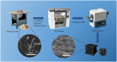 | ||
| Fig. 12 Schematic diagram of pine resin porous carbon electrode preparation by SLS.92 | ||
Hong et al. successfully derived a two-step approach for producing a carbon black/polyamide 12 composite material based on the SLS technology. The first step involved adsorbing the carbon black onto the surface of polyamide 12 powders through ultrasonic and liquid phase-assisted absorption and deposition processes. The composite parts were then sintered in the subsequent SLS process, which is entirely described in Fig. 13. The resulting composite material consists of conductive networks throughout the specimen, which in turn, allow the composite material to exhibit a high level of conductivity. Compared to a compression mold of the same material, the SLS-printed component showed higher levels of conductivity due to aligned channels. Furthermore, the carbon black benefits the adsorption of laser energy due to its higher thermal conductivity than polyamide 12. This work highlights a novel approach for producing materials that can be later printed using SLS 3D printing, overcoming the obstacle of limited material selection.93
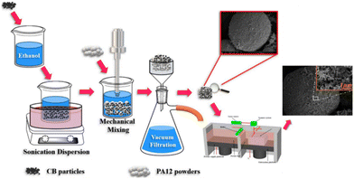 | ||
| Fig. 13 Schematic illustration of the two-step approach for producing carbon black/polyamide 12 composites with a 3D segregated conductive network.93 | ||
Sha et al. devised an automated powder-bed printing method for the in situ growth of 3D graphene foam by manually feeding layers of nickel and sucrose powder and sintering with a CO2 laser. Sucrose served as the carbonaceous solid source for graphene, while the sintered Ni metal functioned as both the catalyst and the template for the growth of graphene, and no high-temperature furnace or tedious growth process was required. The entire process can be seen in Fig. 14. The product was largely porous (∼99.3%), which brought the density down to approximately 0.015 g cm−3. Moreover, the graphene foam had a remarkable storage modulus as well as a high room-temperature damping capacity when compared to other porous graphene foams. This simple and efficient method shows promising applications in fields requiring sound absorption, damping materials, and energy storage devices.94
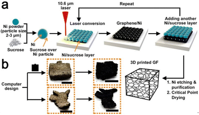 | ||
| Fig. 14 Schematic of in situ synthesis of 3D graphene foam using SLS.94 | ||
Zhu et al. reported a route to fabricate green parts consisting of carbon fiber/SiC composites by the incorporation of SLS and liquid silicon infiltration methods, which is the first time that phenolic resin-coated carbon nanofibers have been used as precursor powders.95 In this study, pores ranging from 15 to 30 μm were produced from intercrossed carbon fibers in the first step of forming the powder and then the green parts composed of powder were prepared by advanced SLS to produce voids with a diameter of 1.5 mm in the lattice structures, which can be clearly observed in Fig. 15. Subsequently, carbon nanofiber/carbon preforms have been prepared by vacuum infiltration and subsequent carbonization. The resulting product of carbon fiber/SiC was synthesized by a second infiltration of liquid silicon. The physical properties were investigated at different laser powers applied in the SLS process, which showed that a higher applied power would cause a lower average pore diameter. Other mechanical properties were also discussed, including density, flexural strength, and fracture toughness, which showed that the mechanical performance can be improved in part by the integration of carbon fibers.
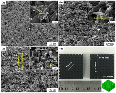 | ||
| Fig. 15 SEM images of (a) the SLS green part, cross-section of (b) the carbonized part and (c) the carbon fiber/C preform; (d) picture of complex green parts with lattice structures. The insets are zoom-in SEM images.95 | ||
Lahtinen and his team of researchers96 skillfully harnessed the capabilities of selective laser sintering (SLS) 3D printing to meticulously fabricate highly porous carbonous electrodes. Graphite powder was mixed into a polyamide-12, polystyrene, or polyurethane matrix for the purpose of fabricating highly porous carbonous electrodes through the utilization of SLS 3D printing. Utilizing the innovative Selective Laser Sintering (SLS) printing technique, all the 3D-printed electrodes exhibited exceptional porosity. Harnessing polyurethane as a pliable supporting matrix, researchers successfully engineered flexible electrodes. Remarkably, these electrodes demonstrated heightened sensitivity to both pressure and mechanical stress. The findings derived from this study elucidate that the synergistic combination of meticulous chemical design, intricate printing material, and the judicious application of SLS 3D printing enables the fabrication of highly customizable, precision electrodes, boasting desirable chemical, physical, mechanical, and flow-through properties, tailored to meet specific functional requirements.
Selective laser sintering is a representative direct writing method.97 Luo et al.98 reported a facile and scalable direct laser writing (DLW)-assisted technique for generating porous carbon platelets (PCPs) with uniform size and arbitrarily designed shapes. This innovative approach leverages CO2 laser irradiation to induce carbonization of a biomass composite sheet. This sheet is formed by infusing sodium lignosulfonate into cellulose paper, thereby producing porous carbon features of arbitrary design. Subsequent water immersion treatment facilitates the spontaneous detachment of the laser-written carbon features, resulting in freestanding PCPs. The fabrication, characterization, and potential applications of PCPs in diverse shapes were explored. These applications span dye adsorption, flexible sensors, and miniaturized supercapacitors.
Although powder bed fusion has been around for years, its application in producing porous carbon is still relatively new. As a result, few materials have been shown to produce porous carbon even for the most promising subcategory, SLS. Nevertheless, this route is advantageous since it produces relatively high carbon yields.91 Furthermore, this process can utilize waste products as the carbon source, making it sustainable and inexpensive. Currently, most SLS research on porous carbon tends to look at preparation and characterization.99–101 Thus, the potential of SLS technology for versatile applications could be further explored. Further research into material selection and synthesis will look at finding composites with desirable powder characteristics, thermal properties,102 and material compatibility,103 which promises to further enhance this process and expand the potential applications.
4. Conclusions and perspectives
In recent years, the fusion of additive manufacturing with traditional methods has emerged as a promising intersection in the development of porous carbon materials for a wide range of applications, delivering cost-effectiveness, control and repeatability. This hybrid approach has enabled the customization of both the macrostructure and microstructure of porous carbon, significantly enhancing material efficiency and optimization for specific applications.Highlighting the technological strides in material fabrication, the integration of Artificial Intelligence (AI) and 3D printing technology has been particularly transformative. This is because AI can potentially predict properties, optimize synthesis processes, and enable high-throughput material screening for porous carbon, minimizing the time and bandwidth needed for research and development. This synergy between AI and 3D printing is expected to greatly benefit porous carbon fabrication and its integration into various high-impact sectors. Based on these integrations, the application of Machine Learning (ML) in 3D printing can enhance material selection, drive design innovation, and optimize fabrication processes. By leveraging vast databases to pinpoint materials and process parameters with optimal properties, synthesis can be more controlled with less overall waste. These improvements will not only streamline workflow but also create avenues for greater sustainability and cost-effectiveness.
Within the scope of 3D printing techniques—namely, material extrusion, vat polymerization, and powder bed fusion—the exploration of porous carbon fabrication has unveiled notable benefits and challenges. The adaptability of these techniques allows for the production of porous carbon with tailored macrostructures and microstructures, offering promising opportunities across various sectors that require specific material architectures. Other aspects, including tailoring printing process precursors for controlled porosity, adding high-performance materials, and refining manufacturing parameters, are also pivotal areas for further exploration. These advancements, coupled with the utilization of AI and ML, hold the potential to surpass existing limitations and provide great opportunities for manufacturing porous carbon and other materials with unparalleled precision and customization.
Author contributions
All authors evaluated the review and approved the final version of the manuscript.Conflicts of interest
There are no conflicts to declare.Acknowledgements
This research is supported by the NASA under 80NSSC21M0333 and LEQSF(2020-24)-LaSPACE. Fei also acknowledged the Chevron Endowed Professorship in Chemical Engineering.References
- S. Wang, D. Chen, Z. X. Zhang, Y. Hu and H. Quan, Sep. Purif. Technol., 2022, 290, 120912 CrossRef CAS.
- H. Guan, Q. Wang, X. Wu, J. Pang, Z. Jiang, G. Chen, C. Dong, L. Wang and C. Gong, Composites, Part B, 2021, 207, 108562 CrossRef CAS.
- M. Avhad, V. Flaud, L. Burel, J. Cavailles, T. Sakpal, L. Lefferts and H. Kaper, Carbon, 2020, 169, 297–306 CrossRef CAS.
- L. Wang and X. Hu, Chem.– Asian J., 2018, 13, 1518–1529 CrossRef CAS PubMed.
- Q. Y. Zhou, L. Tan, T. B. Lv, M. C. Li, J. J. Zhang, Z. Q. Zhao, X. J. Jin, Z. Liu, P. P. Hou, Z. Zeng, S. Deng and G. P. Dai, ACS Appl. Mater. Interfaces, 2023, 15, 3037–3046 CrossRef CAS PubMed.
- M. C. Li, Z. Liu, L. Tan, Q. Y. Zhou, J. J. Zhang, P. P. Hou, X. J. Jin, T. B. Lv, Z. Q. Zhao, Z. Zeng, S. Deng and G. P. Dai, ACS Sustainable Chem. Eng., 2022, 10, 10223–10233 CrossRef CAS.
- W. Tian, H. Zhang, X. Duan, H. Sun, G. Shao and S. Wang, Adv. Funct. Mater., 2020, 30, 1909265 CrossRef CAS.
- K. J. Chen, D. G. Madden, T. Pham, K. A. Forrest, A. Kumar, Q. Y. Yang, W. Xue, B. Space, J. J. Perry, J. P. Zhang, X. M. Chen and M. J. Zaworotko, Angew. Chem., Int. Ed., 2016, 55, 10268–10272 CrossRef CAS PubMed.
- P. Hang, H. Hu and S. Dai, Porous Carbon Supports:Recent Advances with Various Morphologies and Compositions, 2015, vol. 7 Search PubMed.
- M. Ben Mosbah, L. Mechi, R. Khiari and Y. Moussaoui, Processes, 2020, 8, 1–24 CrossRef.
- C. Vix-Guterl, E. Frackowiak, K. Jurewicz, M. Friebe, J. Parmentier and F. Béguin, Carbon, 2005, 43, 1293–1302 CrossRef CAS.
- S. Dutta, A. Bhaumik and K. C. W. Wu, Energy Environ. Sci., 2014, 7, 3574–3592 RSC.
- H. Zhang, Y. Zhu, Q. Liu and X. Li, Appl. Energy, 2022, 306, 118131 CrossRef CAS.
- W. Kai, Z. Shengzhe, Z. Yanting, R. Jun, L. Liwei and L. Yong, Int. J. Electrochem. Sci., 2018, 13, 10766–10773 CrossRef CAS.
- Y. Wang, J. Chen, H. Ihara, M. Guan and H. Qiu, TrAC, Trends Anal. Chem., 2021, 143, 116421 CrossRef CAS.
- M. S. Khosrowshahi, H. Mashhadimoslem, H. Shayesteh, G. Singh, E. Khakpour, X. Guan, M. Rahimi, F. Maleki, P. Kumar and A. Vinu, Adv. Sci., 2023, 10, 2304289 CrossRef CAS PubMed.
- A. K. Mohammed, S. Usgaonkar, F. Kanheerampockil, S. Karak, A. Halder, M. Tharkar, M. Addicoat, T. G. Ajithkumar and R. Banerjee, J. Am. Chem. Soc., 2020, 142, 8252–8261 CrossRef CAS PubMed.
- J. Fonseca and T. Gong, Coord. Chem. Rev., 2022, 462, 214520 CrossRef CAS.
- X. Yang, T. Lv and J. Qiu, Small, 2023, 19, 2300336 CrossRef CAS PubMed.
- Y. Lu, S. Zeng, L. Zhou, X. Huang, Y. Zeng, D. Zheng, W. Xu and X. Lu, Particle and Particle Systems Characterization, 2019, 36, 1900115 CrossRef.
- Y. Zheng, X. Huang, J. Chen, K. Wu, J. Wang and X. Zhang, Materials, 2021, 14, 3911 CrossRef CAS PubMed.
- W. Zong, N. Chui, Z. Tian, Y. Li, C. Yang, D. Rao, W. Wang, J. Huang, J. Wang, F. Lai and T. Liu, Adv. Sci., 2021, 8, 2004142 CrossRef CAS PubMed.
- W. Tian, H. Zhang, X. Duan, H. Sun, G. Shao and S. Wang, Adv. Funct. Mater., 2020, 30, 1909265 CrossRef CAS.
- A. Memetova, I. Tyagi, R. R. Karri, V. Kumar, K. Tyagi, Suhas, N. Memetov, A. Zelenin, T. Pasko, A. Gerasimova, D. Tarov, M. H. Dehghani and K. Singh, Chem. Eng. J., 2022, 446, 137373 CrossRef CAS.
- Q. Zhang, B. Yan, L. Feng, J. Zheng, B. You, J. Chen, X. Zhao, C. Zhang, S. Jiang and S. He, Nanoscale, 2022, 14, 8216–8244 RSC.
- J. Yin, W. Zhang, N. A. Alhebshi, N. Salah and H. N. Alshareef, Small Methods, 2020, 4, 1900853 CrossRef CAS.
- M. A. Mudassir, S. Kousar, M. Ehsan, M. Usama, U. Sattar, M. Aleem, I. Naheed, O. Bin Saeed, M. Ahmad, H. F. Akbar, M. A. Ud Din, T. M. Ansari, H. Zhang and I. Hussain, Renewable Sustainable Energy Rev., 2023, 185, 113594 CrossRef CAS.
- B. A. Praveena, N. Lokesh, A. Buradi, N. Santhosh, B. L. Praveena and R. Vignesh, in Materials Today: Proceedings, Elsevier Ltd, 2022, vol. 52, pp. 1309–1313 Search PubMed.
- A. Jadhav and V. S. Jadhav, Mater. Today: Proc., 2022, 62, 2094–2099 Search PubMed.
- I. Karakurt and L. Lin, Curr. Opin. Chem. Eng., 2020, 28, 134–143 CrossRef.
- M. P. Browne, E. Redondo and M. Pumera, Chem. Rev., 2020, 120, 2783–2810 CrossRef CAS PubMed.
- L. Y. Zhou, J. Fu and Y. He, Adv. Funct. Mater., 2020, 30, 2000187 CrossRef CAS.
- P. Blyweert, V. Nicolas, J. Macutkevic, V. Fierro and A. Celzard, ACS Sustainable Chem. Eng., 2022, 10, 7702–7711 CrossRef CAS.
- S. Saleh Alghamdi, S. John, N. Roy Choudhury and N. K. Dutta, Polymers, 2021, 13, 753 CrossRef PubMed.
- A. Osman and J. Lu, Mater. Sci. Eng., R, 2023, 154, 100734 CrossRef.
- Q. Ge, Z. Li, Z. Wang, K. Kowsari, W. Zhang, X. He, J. Zhou and N. X. Fang, Int. J. Extreme Manuf., 2020, 2, 022004 CrossRef CAS.
- Y. G. Park, I. Yun, W. G. Chung, W. Park, D. H. Lee and J. U. Park, Adv. Sci., 2022, 9, 2104623 CrossRef PubMed.
- R. Y. Tay, Y. Song, D. R. Yao and W. Gao, Mater. Today, 2023, 71, 135–151 CrossRef CAS PubMed.
- D. Thomas, Int. J. Adv. Des. Manuf. Technol., 2016, 85, 1857–1876 CrossRef PubMed.
- A. P. Moreno Madrid, S. M. Vrech, M. A. Sanchez and A. P. Rodriguez, Mater. Sci. Eng., C, 2019, 100, 631–644 CrossRef CAS PubMed.
- J. A. Lewis, Adv. Funct. Mater., 2006, 16, 2193–2204 CrossRef CAS.
- M. Schmid, A. Amado and K. Wegener, J. Mater. Res., 2014, 29, 1824–1832 CrossRef CAS.
- H. Quan, T. Zhang, H. Xu, S. Luo, J. Nie and X. Zhu, Bioact. Mater., 2020, 5, 110–115 Search PubMed.
- J. Shah, B. Snider, T. Clarke, S. Kozutsky, M. Lacki and A. Hosseini, Int. J. Adv. Des. Manuf. Technol., 2019, 104, 3679–3693 CrossRef.
- N. Shahrubudin, T. C. Lee and R. Ramlan, in Procedia Manufacturing, Elsevier B.V., 2019, vol. 35, pp. 1286–1296 Search PubMed.
- M. Spoerk, C. Holzer and J. Gonzalez-Gutierrez, J. Appl. Polym. Sci., 2020, 137, 48545 CrossRef CAS.
- A. Y. Davis, Q. Zhang, J. P. S. Wong, R. J. Weber and M. S. Black, Build. Environ., 2019, 53, 12054–12061 Search PubMed.
- G. H. Loh, E. Pei, J. Gonzalez-Gutierrez and M. Monzón, Appl. Sci., 2020, 10, 4776 CrossRef CAS.
- A. K. Gupta, Krishnanand and M. Taufik, Materials Today: Proceedings, Elsevier Ltd, 2021, vol. 50, pp. 1234–1242 Search PubMed.
- S. J. He, K. Q. Zhang, Y. J. Zou and Z. H. Tian, New Carbon Mater., 2022, 37, 898–917 CrossRef CAS.
- L. L. Jiao and J. H. Sun, in Procedia Engineering, Elsevier Ltd, 2014, vol. 71, pp. 622–628 Search PubMed.
- J. J. Schwartz, MRS Bull., 2022, 47, 628–641 CrossRef CAS PubMed.
- M. Pagac, J. Hajnys, Q. P. Ma, L. Jancar, J. Jansa, P. Stefek and J. Mesicek, Polymers, 2021, 13, 1–20 CrossRef PubMed.
- W. Li, L. S. Mille, J. A. Robledo, T. Uribe, V. Huerta and Y. S. Zhang, Adv. Healthc. Mater., 2020, 9, e2000156 CrossRef PubMed.
- G. González, D. Baruffaldi, C. Martinengo, A. Angelini, A. Chiappone, I. Roppolo, C. F. Pirri and F. Frascella, Nanomaterials, 2020, 10, 1–13 Search PubMed.
- W. Piedra-Cascón, V. R. Krishnamurthy, W. Att and M. Revilla-León, J. Dent., 2021, 109, 103630 CrossRef PubMed.
- K. L. Sampson, B. Deore, A. Go, M. A. Nayak, A. Orth, M. Gallerneault, P. R. L. Malenfant and C. Paquet, ACS Appl. Polym. Mater., 2021, 3, 4304–4324 CrossRef CAS.
- W. L. Ng, J. M. Lee, M. Zhou, Y. W. Chen, K. X. A. Lee, W. Y. Yeong and Y. F. Shen, Biofabrication, 2020, 12, 022001 CrossRef CAS PubMed.
- Y. Zhang, Z. Dong, C. Li, H. Du, N. X. Fang, L. Wu and Y. Song, Nat. Commun., 2020, 11, 4685 CrossRef CAS PubMed.
- D. Dev Singh, T. Mahender and A. Raji Reddy, Materials Today: Proceedings, Elsevier Ltd, 2021, vol. 46, pp. 350–355 Search PubMed.
- S. Sun, M. Brandt and M. Easton, Laser Additive Manufacturing: Materials, Design, Technologies, and Applications, Elsevier Inc., 2017, pp. 55–77 Search PubMed.
- A. Awad, F. Fina, A. Goyanes, S. Gaisford and A. W. Basit, Int. J. Pharm., 2020, 586, 119594 CrossRef CAS PubMed.
- F. Bosio, A. Aversa, M. Lorusso, S. Marola, D. Gianoglio, L. Battezzati, P. Fino, D. Manfredi and M. Lombardi, Mater Des, 2019, 181, 107949 CrossRef CAS.
- R. Singh, A. Gupta, O. Tripathi, S. Srivastava, B. Singh, A. Awasthi, S. K. Rajput, P. Sonia, P. Singhal and K. K. Saxena, in Materials Today: Proceedings, Elsevier Ltd, 2019, vol. 26, pp. 3058–3070 Search PubMed.
- M. Launhardt, A. Wörz, A. Loderer, T. Laumer, D. Drummer, T. Hausotte and M. Schmidt, Polym. Test., 2016, 53, 217–226 CrossRef CAS.
- A. Shahzad and I. Lazoglu, Composites, Part B, 2021, 225, 109249 CrossRef CAS.
- W. Zhang, H. Liu, X. Zhang, X. Li, G. Zhang and P. Cao, Adv. Funct. Mater., 2021, 31, 2104909 CrossRef CAS.
- Z. Liu, X. Zhou and C. Jun Liu, Diamond Relat. Mater., 2019, 95, 121–126 CrossRef CAS.
- X. Zhou and C. Jun Liu, Catal. Today, 2020, 347, 2–9 CrossRef CAS.
- L. Yang, X. Wang, S. Yin, X. Shi, L. Wang, P. She, Y. Song, Z. Liu and H. Sun, Sep. Purif. Technol., 2023, 320, 124116 CrossRef CAS.
- B. Yao, H. Peng, H. Zhang, J. Kang, C. Zhu, G. Delgado, D. Byrne, S. Faulkner, M. Freyman, X. Lu, M. A. Worsley, J. Q. Lu and Y. Li, Nano Lett., 2021, 21, 3731–3737 CrossRef CAS PubMed.
- Q. Li, Q. Dong, J. Wang, Z. Xue, J. Li, M. Yu, T. Zhang, Y. Wan and H. Sun, J. Power Sources, 2022, 542, 231810 CrossRef CAS.
- H. Jeong, J. H. Lee, S. Kim, S. Han, H. Moon, J. Y. Song and A. Y. Park, Sci. Rep., 2023, 13, 21297 CrossRef CAS PubMed.
- K. Parate, S. V. Rangnekar, D. Jing, D. L. Mendivelso-Perez, S. Ding, E. B. Secor, E. A. Smith, J. M. Hostetter, M. C. Hersam and J. C. Claussen, ACS Appl. Mater. Interfaces, 2020, 12, 8592–8603 CrossRef CAS PubMed.
- Z. Guo, P. Yu, Y. Liu and J. Zhao, Compos Sci Technol, 2021, 201, 108530 CrossRef CAS.
- S. S. Hossain and K. Lu, Ceram. Int., 2023, 49, 10199–10212 CrossRef CAS.
- C. Oztan and V. Coverstone, Acta Astronaut., 2021, 180, 130–140 CrossRef CAS.
- M. L. Sesso, S. Slater, J. Thornton and G. V. Franks, J. Am. Ceram. Soc., 2021, 104, 4977–4990 CrossRef CAS.
- H. Steldinger, A. Esposito, K. Brunnengräber, J. Gläsel and B. J. M. Etzold, Adv. Sci., 2019, 6, 1901340 CrossRef CAS PubMed.
- P. Wang, H. Zhang, H. Wang, D. Li, J. Xuan and L. Zhang, Adv. Mater. Technol., 2022, 7, 2100672 CrossRef.
- H. Jiang, S. Huang, H. Lv, D. Ge, X. He, P. Zhou, K. Xiao and Y. Zhang, Water Res, 2022, 225, 119134 CrossRef CAS PubMed.
- Y. Katsuyama, N. Haba, H. Kobayashi, K. Iwase, A. Kudo, I. Honma and R. B. Kaner, Adv. Funct. Mater., 2022, 32, 2201544 CrossRef CAS.
- A. Kudo, K. Kanamaru, J. Han, R. Tang, K. Kisu, T. Yoshii, S. Ichi Orimo, H. Nishihara and M. Chen, Small, 2023, 19, 2301525 CrossRef CAS PubMed.
- M. van der Heijden, M. Kroese, Z. Borneman and A. Forner-Cuenca, Adv. Mater. Technol., 2023, 8, 2300611 CrossRef CAS.
- S. Chandrasekaran, J. B. Forien, P. G. Campbell, J. S. Oakdale, J. A. Mancini, M. A. Worsley and J. Biener, Carbon, 2021, 179, 125–132 CrossRef CAS.
- Q. Huang, S. Ni, M. Jiao, X. Zhong, G. Zhou and H. M. Cheng, Small, 2021, 17, 2007676 CrossRef CAS PubMed.
- J. Martín-Montal, J. Pernas-Sánchez and D. Varas, Polymers, 2021, 13, 1147 CrossRef PubMed.
- E. Johansson, O. Lidström, J. Johansson, O. Lyckfeldt and E. Adolfsson, Materials, 2017, 10, 138 CrossRef PubMed.
- E. O. Olakanmi, R. F. Cochrane and K. W. Dalgarno, Prog. Mater. Sci., 2015, 74, 401–477 CrossRef CAS.
- P. J. Brown, Selective Laser Sintering (SLS) rapid protytping technology: a review of medical applications, 53rd Annual Rocky Mountain Bioengineering Symposium, RMBS 2016 and 53rd International ISA Biomedical Sciences Instrumentation Symposium, 2016.
- K. A. Acord, A. D. Dupuy, U. Scipioni Bertoli, B. Zheng, W. C. West, Q. N. Chen, A. A. Shapiro and J. M. Schoenung, J. Mater. Process. Technol., 2021, 288, 116827 CrossRef CAS.
- S. Guo, J. Li, L. Zhang and Y. Li, Mater. Lett., 2023, 330, 133300 CrossRef CAS.
- R. Hong, Z. Zhao, J. Leng, J. Wu and J. Zhang, Composites, Part B, 2019, 176, 107214 CrossRef CAS.
- J. Sha, Y. Li, R. Villegas Salvatierra, T. Wang, P. Dong, Y. Ji, S. K. Lee, C. Zhang, J. Zhang, R. H. Smith, P. M. Ajayan, J. Lou, N. Zhao and J. M. Tour, ACS Nano, 2017, 11, 6860–6867 CrossRef CAS PubMed.
- W. Zhu, H. Fu, Z. Xu, R. Liu, P. Jiang, X. Shao, Y. Shi and C. Yan, J. Eur. Ceram. Soc., 2018, 38, 4604–4613 CrossRef CAS.
- E. Lahtinen, E. Kukkonen, J. Jokivartio, J. Parkkonen, J. Virkajärvi, L. Kivijärvi, M. Ahlskog and M. Haukka, ACS Appl. Energy Mater., 2019, 2, 1314–1318 CrossRef CAS.
- E. Hwang, J. Hong, J. Yoon and S. Hong, Materials, 2022, 15, 6006 CrossRef CAS PubMed.
- J. Luo, Y. Yao, M. Niu, X. Duan, R. Wang and T. Liu, ACS Omega, 2019, 4, 5870–5878 CrossRef CAS PubMed.
- F. Yang, N. Zobeiry, R. Mamidala and X. Chen, Mater. Today Commun., 2023, 34, 105279 CrossRef CAS.
- M. E. Korkmaz, M. K. Gupta, G. Robak, K. Moj, G. M. Krolczyk and M. Kuntoğlu, J. Manuf. Process., 2022, 81, 1040–1063 CrossRef.
- F. E. Jabri, A. Ouballouch, L. Lasri and R. El Alaiji, J. Achiev. Mater. Manuf. Eng., 2023, 118, 5–17 Search PubMed.
- M. Schmid and K. Wegener, AIP Conference Proceedings, American Institute of Physics Inc., 2016, vol. 1779 Search PubMed.
- A. Jandyal, I. Chaturvedi, I. Wazir, A. Raina and M. I. Ul Haq, Sustain. Operat. Comput., 2022, 3, 33–42 CrossRef.
Footnote |
| † These authors contributed to the manuscript equally. |
| This journal is © The Royal Society of Chemistry 2024 |


