 Open Access Article
Creative Commons Attribution 3.0 Unported Licence
Rapid investigation of the effect of binary and ternary solvent gradient mixtures on reaction outcomes using a continuous flow system†
Dawid
Drelinkiewicz
 a,
Tom J. A.
Corrie
b and
Richard J.
Whitby
 *a
*a
aSchool of Chemistry, Faculty of Engineering and Physical Sciences, The University of Southampton, Southampton, UK. E-mail: rjw1@soton.ac.uk
bJealott's Hill International Research Centre, Syngenta Ltd., Bracknell, UK
First published on 19th October 2023
Abstract
In a continuous flow process, generating a gradient of solvent composition with time and monitoring of the reaction mixture as it leaves the reactor allows for rapid generation of reaction information against a full range of solvent mixture compositions. The methodology was developed by screening binary solvent mixtures in a SNAr reaction in which previously reported effects were efficiently reproduced. Binary and ternary solvent gradients were then applied to an imine forming reaction revealing interesting non-linear effects.
Introduction
Solvents are vital components of chemical transformations, as the composition of the liquid medium can affect the overall process reactivity and/or selectivity, change the structure of the reaction catalyst, stabilise or destabilise reaction reagents and intermediate species, and exert other effects.1,2 Solvents can be efficiently characterised by means of the principal component analysis (PCA)3,4 to aid the selection of the optimal reaction medium.Solvents are omnipresent in academia and agrochemical, fine and speciality chemicals, and pharmaceutical industries, as plethora of the R&D and manufacturing operations are run on a solvent-intensive basis,2,5–8 thus making them an important parameter to consider during process design and optimisation. Currently, screening of various solvents is a standard practice when developing or optimising chemical transformations and it is usually performed as a series of experiments in which only used medium varies, after which the reaction outcome (e.g. yield) is compared and the best solvent is chosen. Particularly notable are recent methods using segmented flow which allow a series of solvents to be rapidly screened using very small amounts of material.9,10
The potential benefits of changing the pure solvents used as reaction mediums also extend to the use of mixtures of solvents, but this is rarely investigated, although there are examples where a specific solvent mixture is higher yielding11 or more selective12 compared to the pure solvents. In batch or steady-state flow chemistry, each mixture requires a separate experiment discouraging the use of more than a few solvents compositions.
Continuous flow reactors have proven to be useful systems for process investigation and optimisation as conditions are precisely controlled, and readily automated. Usually, reactions are carried out under steady state conditions where an experiment tests a single set of conditions, and with only one timepoint (the residence time of the reactor at the flow rate used) sampled. Recently the use of a sudden13–16 or controlled17–23 flow rate change to allow outcomes from a continuous range of reaction times to be determined in a single experiment has been reported. In a similar way, switching off the light during photochemical reactions has been used to allow a single experiment to provide a continuous range of light exposure times.24 A particularly powerful method, which has no equivalent with batch reactors, is to dynamically control the flow rate of several pumps in order to vary the concentration of a reagent component during a single experiment.16,20 Continuous data on the effect of the concentration of the varied component is thus obtained, albeit at a single time point. The use of solvent gradients is routine in chromatographic separations.
Herein we present a novel methodology using a flow reactor and an in situ generated continuous gradient of solvent composition as the reaction medium to rapidly obtain process information on the use of mixed solvents. The technique allows the effect of all compositions of a binary solvent mixture on a reaction outcome to be determined in two short experiments. It was extended to look at the effect of the application of ternary solvent mixtures.
Results and discussion
Flow setup and methodology development
The methodology used relied on delivering the studied solvents to the flow system using two pumps, which flow rates were programmed to step-change simultaneously, increasing the flow rate of one pump and decreasing the flow rate of the other pump, while keeping the total flow rate of both pumps constant. Both streams with studied solvents are then combined with the reagents stream, mixed, and flowed into the reactor in which the chemical transformation occurs.After exiting from the reactor, the reaction mixture can be monitored using in-line monitoring (e.g. UV-vis or IR) or can be collected into fractions and analysed by off-line methods (e.g. GC, HPLC, NMR) (Fig. 1). In flow systems used for studies described ibid. the reagents are dissolved in one of the solvents used, thus this solvent is always present and limits the range of studied solvents mixture. Such issue can be overcome by injecting neat reagents allowing for screening of whole range of used solvents in one experiment however, injection of neat reagents using mesoscale flow systems usually proves to be problematic. A practical solution is to perform a set of two complementary experiments in which solvents are used interchangeably, which also allows for additional diagnostics of performed experiments as the results ought to overlap in the common regions of the used mixture.
Solvents mixtures studies in SNAr reaction
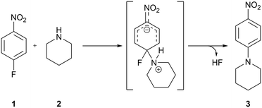
To develop the method, we chose the well-studied nucleophilic displacement between 1-fluoro-4-nitrobenzene 1 and piperidine 2 (Scheme 1) since there is a known balance between reaction medium polarity and the presence of hydrogen-bond donors on the reaction rate.1,25–30 A flow system consisting of two pumps delivering the reagents, 1-fluoro-4-nitrobenzene 1 and piperidine 2, respectively, and two pumps delivering the studied solvents were used (Fig. 2). Both reagents' and solvents' lines were then mixed in a micromixer chip, joined together, and directed to the HPLC type mixer. The micromixer chip creates a lamination of the flow streams, which reduces the diffusion distances. Additionally, at the flow rates used swirling occurs reducing mixing time even further. On the other hand the HPLC-type mixer relies on creating a turbulent flow area that increases mixing efficiency. The incorporation of mixers proved to be crucial in these studies, as when mixing was insufficient, different results were obtained for the same nominal solvent composition when solvents A and B were swapped (see ESI†). After mixing all reaction components, the reaction stream was directed to the reactor (stainless steel tubing submersed in high-precision thermostatic oil bath), a back-pressure regulator, a cooling coil, and then to flow UV-vis cell for in situ reaction monitoring.Optimisation of flow conditions was performed using DMF as a solvent with the aim of obtaining approximately 50% reaction yield, as further studies were meant to show either increase or decrease in reaction outcome when using different solvent mixtures. Optimal reaction conditions affording the product 3 in 40% yield were achieved at 216 seconds residence time, corresponding to 2.5 mL min−1 flow rate, reactor temperature of 110 °C, and starting materials effective concentrations (while in the flow reactor) of 16.0 and 40.0 mM, of 1-fluoro-4-nitrobenzene 1 and piperidine 2, respectively.
Corrections for relevant physicochemical phenomena
UV-vis absorption is highly dependent on the medium used during measurement due to solvatochromic effects, thus molar extinction coefficients of SNAr reaction product 3 were determined for all used solvents and a linear relationship between solvents mixture composition and extinction coefficient was used (see ESI†). No corrections were made for the volume changes induced by mixing solvents and for the thermal expansion of the liquids, as these are small (see ESI†). Although laminar flow and hence Taylor dispersion is expected in the meso-scale flow this does not significantly affect the results except at the start and end of the composition gradients, where there is some ‘averaging in’ of the constant composition region leading to the curves flattening at these points. The variation of dispersion with solvent composition did not give visible changes.Investigation of binary solvents mixtures in SNAr reaction
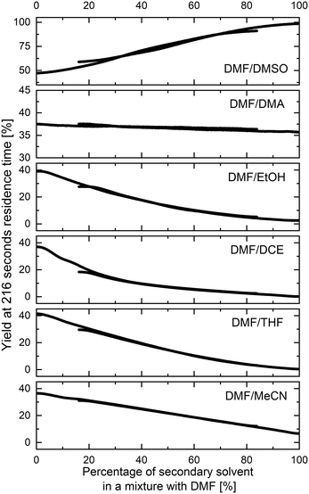
The methodology for studying solvents mixtures effects was applied in the SNAr reaction between 1 and 2, using mixtures of solvents and DMF in the above-mentioned flow system (Fig. 2) with in-line UV-vis monitoring. A wide variety of solvent mixtures were evaluated (18 in total, see ESI† for full account), a few examples of which are presented below (Fig. 3). In each case, two experiments (with solvents A and B swapped) were carried out to allow for the full range of compositions to be examined. The curves ‘flattening’ at the ends of each line is due to dispersive mixing as described above.When DMSO was used as a secondary solvent in a mixture with DMF, a gradual increase in reaction yield at the fixed residence time was observed throughout the whole range of solvent compositions, reaching nearly quantitative yield when using pure DMSO. Application of DMF/DMA mixture resulted only in slight change of the reaction outcome. When alcohols were used as secondary solvents and mixed with DMF, reaction yields were decreasing non-linearly with the increase of alcohol amount, as presented in the example of DMF and EtOH mixture. A similar non-linear trend was observed when using mixtures of chlorinated solvents with DMF, visible in the example of DMF and DCE mixture. Mixtures of ethers and other aprotic organic solvents (acetone, ethyl acetate, toluene, and acetonitrile) showed mostly a linear decrease in the yield of 3 with an increase in the amount of the less polar solvent.
All results are in agreement with the current understanding of solvent effects in SNAr reaction. Increasing the polarity of the aprotic solvent (DMF to DMSO or MeCN to DMF) increased reaction rate, whereas the addition of a protic HBD solvent (DMF to EtOH) resulted in a non-linear reduction of the rate.
Validation of the flow SNAr reaction solvents mixtures screening
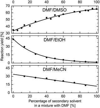
Validation of the trends obtained from flow solvents studies experiments was executed by performing a set of classical batch experiments for eleven selected solvent mixtures (see ESI†). Three solvent mixtures are presented here, namely DMF and MeCN, DMF and DMSO, and DMF and EtOH (Fig. 4), as the results obtained from flow studies showed different trends for these mixtures. Trends obtained from batch experiments are in excellent agreement with the results obtained from flow experiments. Note that only trends are compared and not the absolute values of the reaction yields, as the batch and flow experiments were performed using different conditions (see ESI†). The experiments in flow were done with superheating the reaction mixture to 110 °C, which for many solvents is not compatible with reactors limited to atmospheric pressure so temperature of 25 °C and 120 minutes reaction time were used as the batch conditions.Solvents mixtures studies in imine formation reaction
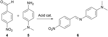
The developed methodology was then used in a mechanistically more complex process since it is possible that in such, a specific mixture of solvents would afford faster reactions than when just using pure solvent. Thus, a second model reaction studied was the formation of imine, as this transformation is known to be highly dependent on the acidity (pKa) of the used catalyst which depends on the used reaction medium,31 and due to various possible pathways,32,33 each of which proceeds through an intermediates that could be affected differently by the solvent change.A reaction between 4-nitrobenzaldehyde 4 and N,N-dimethylphenylene-1,4-diamine 5 (Scheme 2) catalysed by acid, was chosen for our studies as the formed imine 6 maximum of absorbance lies at around 450 nm,34 which allows for in situ reaction monitoring using UV-vis spectroscopy. Reaction conditions affording the imine 6 in approximately 40% yield using 1,2-dichloroethane as reaction medium, allowing for further determination of either increase or decrease of reaction yield when using various solvents mixtures, were achieved at 240 seconds residence time corresponding to 2.25 mL min−1 flow rate, reactor temperature of 110 °C, and starting materials effective concentrations (while in the flow reactor) of 3.3 mM each.
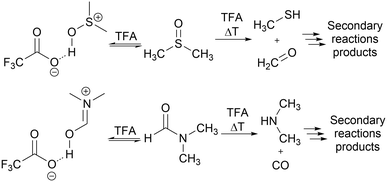
The flow system used for studying solvent effects in imine formation reaction differs from the previously used system for SNAr reaction, by an additional 5th flow stream, in which catalyst (trifluoroacetic acid) is dissolved in a non-reactive solvent (Fig. 5). Dissolving the TFA in, for example DMSO or DMF, can result in protonation of solvents by TFA35–37 and TFA-catalysed degradation38–43 (Scheme 3), which reduce in situ concentration of free acid and alter the reaction stoichiometry, thus affecting the results obtained from the solvent studies experiments. Due to that, in the imine formation experiments the TFA is dissolved in DCE, which slightly restricts the range of the studied solvents composition, since there is always a constant amount of DCE injected into the reaction mixture but allows for the catalyst to be mixed with the reaction medium directly before the reactor, minimising the amount of the TFA used for the formation of undesired byproducts.
 | ||
| Fig. 5 Flow setup and reaction conditions used in solvents mixtures studies in imine formation reaction. | ||
Similarly, to the studies performed for SNAr reaction, the molar extinction coefficient of imine 6 was determined for all used solvents (see ESI†). Again, no corrections for liquids contraction or expansion were used. Changes to the UV absorbance of imine 6 due to protonation by TFA was investigated (see ESI†) and addition of 0.05 equivalents of (the same amount as used in studies described ibid.) resulted only in 5.6% decrease of imine absorbance thus this effect was neglected, and no correction was applied.
Investigation of binary solvents mixtures in imine formation
The methodology for studying solvent mixtures was then applied in the imine formation reaction between 4 and 5, using 1,2-dichloroethane (DCE) as the primary solvent (Fig. 6).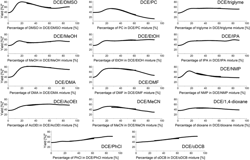 | ||
| Fig. 6 Results of binary solvents mixtures studies in imine formation reaction under continuous flow conditions. aYield at fixed residence time of 240 seconds. | ||
Interestingly, most of the obtained results show non-linear effects with the highest yield of imine under the fixed residence time used being obtained for a specific mixture of both solvents. When the DMSO/DCE mixture was studied, the best yield was obtained using 20% DMSO in DCE affording the imine with an 80% yield. For a 67% DMSO in DCE mixture a local minimum reaction yield of 56% was observed. Mixtures of DCE with triglyme or alcohols showed that addition of small amounts of the latter significantly increases the reaction yield. For DCE/alcohols mixtures a local maximum at around 80% alcohol in DCE is present. Additionally, for DCE/MeOH mixture, a local maximum at around 17% MeOH in DCE is present. Mixtures of DCE with DMF, DMA, and NMP showed that approximately 20–30% amide in DCE is the highest yielding mixture, with DMF, DMA, and NMP mixtures affording the imine in 83%, 74%, and 61%, respectively. Similarly, mixtures of DCE with ethyl acetate, acetonitrile, or 1,4-dioxane afforded the imine in higher yields when using a mixture of two solvents, rather than a singular pure solvent. The mixture of DCE with other chlorinated solvents, such as chlorobenzene or oDCB generally showed a linear effect.
Validation of the flow imine formation reaction binary solvents mixtures screening
In order to validate the obtained results, a set of steady-state flow experiments with reaction conditions identical to that used in solvent studies experiments were performed. All flow streams were connected to the same solvents mixture with a predefined solvents ratio, in which the reagents were premixed. Apart from using in-line UV-vis monitoring during validation experiments, reaction mixtures were also collected and imine 6 was isolated. Validation was performed for DCE/DMSO and DCE/MeOH solvents mixtures (Fig. 7), as they exhibit interesting non-linear dependencies of solvents composition on reaction yields with local maxima and minima present. Results obtained from validation experiments showed excellent correlation with the results obtained from the flow studies with in situ generated solvents composition gradient.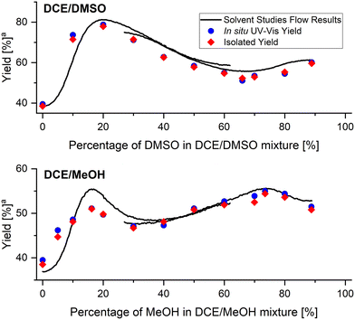 | ||
| Fig. 7 Comparison of flow and validation results of imine formation reaction. aYield at fixed residence time of 240 seconds. | ||
Design of experiment for screening of ternary solvents mixtures in imine formation reaction
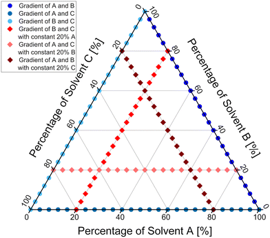
The developed methodology was then extended to study ternary mixtures of solvents. In order to cover the chemical space of interest as efficiently as possible with only few runs, the experiments were designed in two series. The first series was designed to cover the boundary region of the ternary mixture, meaning that mixtures of only two solvents were used, thus the exact same procedure as for studies of binary mixtures was employed. Datapoints distribution and flow conditions derived from the first series of experiments are marked on Fig. 9 in shades of blue. The second series of experiments was designed to cover the inner region of the ternary mixture. To achieve that, a constant amount of one of three solvents was introduced into the flow system, while the other two solvents' ratio was varied. Through the careful design of the experiment, it was judged that a constant amount of 20% of one of the solvents will give the best coverage of the inner region of the ternary mixture. Datapoints distribution and flow conditions for the second series of experiments are marked on Fig. 9 in shades of red. More experiments could be performed to achieve better coverage of the inner region of the ternary mixture and provide more accurate results. Since we wanted the methodology to be fast and attractive for the purposes of the process development and optimisation, a balance between the number of experiments and coverage of the chemical space was chosen. Additionally, the flow setup was changed, so that the outlet of the solvents and TFA micromixer chip was directed to the inlet of the reagents mixing chip, to provide even better mixing for all the streams used (Fig. 8).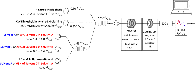 | ||
| Fig. 8 Flow setup and reaction conditions used in studies of ternary solvents mixtures in imine formation reaction. | ||
Investigation of ternary solvents mixtures in imine formation
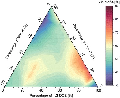
The methodology was then used to study the ternary mixtures of DCE/DMSO/MeOH and oDCB/DMF/EtOAc. The analysis of the results obtained for the DCE/DMSO/MeOH mixture (Fig. 10) shows two local maxima of imine formation, first one at around 75![[thin space (1/6-em)]](https://www.rsc.org/images/entities/char_2009.gif) :
:![[thin space (1/6-em)]](https://www.rsc.org/images/entities/char_2009.gif) 25
25![[thin space (1/6-em)]](https://www.rsc.org/images/entities/char_2009.gif) :
:![[thin space (1/6-em)]](https://www.rsc.org/images/entities/char_2009.gif) 0 ratio of solvents, respectively, affording the imine in approximately 75% yield at the fixed residence time used, and second one at around 20
0 ratio of solvents, respectively, affording the imine in approximately 75% yield at the fixed residence time used, and second one at around 20![[thin space (1/6-em)]](https://www.rsc.org/images/entities/char_2009.gif) :
:![[thin space (1/6-em)]](https://www.rsc.org/images/entities/char_2009.gif) 20
20![[thin space (1/6-em)]](https://www.rsc.org/images/entities/char_2009.gif) :
:![[thin space (1/6-em)]](https://www.rsc.org/images/entities/char_2009.gif) 60 ratio of solvents, respectively, affording the imine in approximately 65% yield. Additionally, a region of low imine yield (approx. 35%) was found at around 0
60 ratio of solvents, respectively, affording the imine in approximately 65% yield. Additionally, a region of low imine yield (approx. 35%) was found at around 0![[thin space (1/6-em)]](https://www.rsc.org/images/entities/char_2009.gif) :
:![[thin space (1/6-em)]](https://www.rsc.org/images/entities/char_2009.gif) 80
80![[thin space (1/6-em)]](https://www.rsc.org/images/entities/char_2009.gif) :
:![[thin space (1/6-em)]](https://www.rsc.org/images/entities/char_2009.gif) 20 ratio of solvents, respectively.
20 ratio of solvents, respectively.
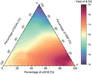
Analysis of the results obtained from the oDCB/DMF/EtOAc mixture (Fig. 11) shows that the maximum of imine formation in this ternary mixture lies at around 85![[thin space (1/6-em)]](https://www.rsc.org/images/entities/char_2009.gif) :
:![[thin space (1/6-em)]](https://www.rsc.org/images/entities/char_2009.gif) 10
10![[thin space (1/6-em)]](https://www.rsc.org/images/entities/char_2009.gif) :
:![[thin space (1/6-em)]](https://www.rsc.org/images/entities/char_2009.gif) 5 ratio of solvents, respectively, affording the imine in 90% yield at the fixed residence time used. Further addition of either DMF or EtOAc generally lowered the yield however, the effect was bigger for DMF, which afforded the imine in 30% yield (in pure DMF), whereas the imine in pure EtOAc was obtained in 60% yield.
5 ratio of solvents, respectively, affording the imine in 90% yield at the fixed residence time used. Further addition of either DMF or EtOAc generally lowered the yield however, the effect was bigger for DMF, which afforded the imine in 30% yield (in pure DMF), whereas the imine in pure EtOAc was obtained in 60% yield.
Conclusions
In summary, we report a novel technique for rapid investigation of the effects of applying binary and ternary solvent mixtures on organic transformations performed in a continuous flow system. The methodology is based on the generation of solvents composition gradient using variable flow rates of two pumps delivering the solvents while keeping their total flow rate constant and injecting the gradient into a working reaction stream. The paramount advantage of such technique is time efficiency and operational simplicity, as the whole range of the used solvents mixture can be screened in short series of automated experiments. With a retention time chosen for partial conversion it gives information on the effect of solvent on the reaction rate and selectivity. Using a retention time which ensures that the reaction is complete, for example with fast reactions, it gives information of the effect of solvent on selectivity (i.e. the reaction yield).A SNAr reaction was used in methodology development and the relative reaction rates using binary mixtures of solvents with DMF showed full agreement with the current understanding of the solvent effects. Validation of the method using batch reactions was in excellent agreement with the flow results. The technique was used in a mechanistically complex reaction, imine formation, and obtained results for binary mixtures of solvents with DCE showed non-linear reaction profiles with local maxima and minima present. The steady-state flow validation procedure showed excellent correlation with the solvent gradient flow results and illustrated that many batch reactions would be needed to obtain the trends revealed with a single flow experiment using solvent gradients.
The methodology was also extended to study ternary solvent mixtures, allowing for rapid screening of the full range of such. Mixtures of DCE/DMSO/MeOH and oDCB/DMF/EtOAc were screened in a series of short experiments, and dependency of the product yield at a fixed residence time against solvents composition was established for the entire range of the ternary mixtures.
Author contributions
Dawid Drelinkiewicz – conceptualisation, data curation, formal analysis, investigation, methodology, software, validation, visualisation, writing – original draft, writing – review & editing; Tom J. A. Corrie – conceptualisation, supervision, writing – review & editing; Richard J. Whitby – conceptualisation, funding acquisition, methodology, resources, supervision, writing – review & editing.Conflicts of interest
There are no conflicts to declare.Acknowledgements
We wish to thank Vapourtec Ltd for their excellent customer service. We are grateful to Syngenta (Jeallot's Hill) and a Southampton University Vice-Chancellors award for funding this work. Research infrastructure was supported by EPSRC (UK) core capability grant (EP/K039466).References
- C. Reichardt and T. Welton, Solvents and Solvent Effects in Organic Chemistry, Wiley-VCH, 4th edn, 2010 Search PubMed.
- J. J. Varghese and S. H. Mushrif, React. Chem. Eng., 2019, 4, 165–206 RSC.
- L. J. Diorazio, D. R. J. Hose and N. K. Adlington, Org. Process Res. Dev., 2016, 20, 760–773 CrossRef CAS.
- P. M. Murray, F. Bellany, L. Benhamou, D.-K. Bučar, A. B. Tabor and T. D. Sheppard, Org. Biomol. Chem., 2016, 14, 2373–2384 RSC.
- D. J. C. Constable, C. Jimenez-Gonzalez and R. K. Henderson, Org. Process Res. Dev., 2007, 11, 133–137 CrossRef CAS.
- L. Shuai and J. Luterbacher, ChemSusChem, 2016, 9, 133–155 CrossRef CAS.
- C. Capello, U. Fischer and K. Hungerbühler, Green Chem., 2007, 9, 927–934 RSC.
- C. J. Clarke, W.-C. Tu, O. Levers, A. Bröhl and J. P. Hallett, Chem. Rev., 2018, 118, 747–800 CrossRef CAS.
- B. J. Reizman and K. F. Jensen, Chem. Commun., 2015, 51, 13290–13293 RSC.
- D. Perera, J. W. Tucker, S. Brahmbhatt, C. J. Helal, A. Chong, W. Farrell, P. Richardson and N. W. Sach, Science, 2018, 359, 429–434 CrossRef CAS.
- W. Ghezali, K. D. O. Vigier, R. Kessas and F. Jérôme, Green Chem., 2015, 17, 4459–4464 RSC.
- A. K. Chew, T. W. Walker, Z. Shen, B. Demir, L. Witteman, J. Euclide, G. W. Huber, J. A. Dumesic and R. C. Van Lehn, ACS Catal., 2020, 10, 1679–1691 CrossRef CAS.
- S. Mozharov, A. Nordon, D. Littlejohn, C. Wiles, P. Watts, P. Dallin and J. M. Girkin, J. Am. Chem. Soc., 2011, 133, 3601–3608 CrossRef CAS.
- T. Durand, C. Henry, D. Bolien, D. C. Harrowven, S. Bloodworth, X. Franck and R. J. Whitby, React. Chem. Eng., 2016, 1, 82–89 RSC.
- C. P. Haas, S. Biesenroth, S. Buckenmaier, T. van de Goor and U. Tallarek, React. Chem. Eng., 2020, 5, 912–920 RSC.
- L. Schrecker, J. Dickhaut, C. Holtze, P. Staehle, M. Vranceanu, K. Hellgardt and K. K. (Mimi) Hii, React. Chem. Eng., 2023, 8, 41–46 RSC.
- J. S. Moore and K. F. Jensen, Angew. Chem., Int. Ed., 2014, 53, 470–473 CrossRef CAS PubMed.
- C. A. Hone, N. Holmes, G. R. Akien, R. A. Bourne and F. L. Muller, React. Chem. Eng., 2017, 2, 103–108 RSC.
- K. C. Aroh and K. F. Jensen, React. Chem. Eng., 2018, 3, 94–101 RSC.
- F. Florit, A. M. K. Nambiar, C. P. Breen, T. F. Jamison and K. F. Jensen, React. Chem. Eng., 2021, 6, 2306–2314 RSC.
- C. J. Taylor, M. Booth, J. A. Manson, M. J. Willis, G. Clemens, B. A. Taylor, T. W. Chamberlain and R. A. Bourne, Chem. Eng. J., 2021, 413, 127017 CrossRef CAS.
- J. P. McMullen and B. M. Wyvratt, React. Chem. Eng., 2022, 8, 137–151 RSC.
- S. D. Schaber, S. C. Born, K. F. Jensen and P. I. Barton, Org. Process Res. Dev., 2014, 18, 1461–1467 CrossRef CAS.
- D. Drelinkiewicz, S. T. Alston, T. Durand and R. J. Whitby, React. Chem. Eng., 2023, 8, 2134–2140 RSC.
- P. M. E. Mancini, R. D. Martinez, L. R. Vottero and N. S. Nudelman, J. Chem. Soc., Perkin Trans. 2, 1984, 1133–1138 RSC.
- R. D. Martinez, P. M. E. Mancini, L. R. Vottero and N. S. Nudelman, J. Chem. Soc., Perkin Trans. 2, 1986, 1427–1431 RSC.
- N. S. Nudelman, P. M. E. Mancini, R. D. Martinez and L. R. Vottero, J. Chem. Soc., Perkin Trans. 2, 1987, 951–954 RSC.
- H. Suhr, Ber. Bunsenges. Phys. Chem., 1963, 67, 893–898 CrossRef CAS.
- H. Suhr, Chem. Ber., 1964, 97, 3277–3283 CrossRef CAS.
- H. Suhr, Justus Liebigs Ann. Chem., 1965, 687, 175–182 CrossRef CAS.
- R. A. Y. Jones, Physical and mechanistic organic chemistry, Cambridge University Press, Cambridge, New York, 1979 Search PubMed.
- M. Ciaccia and S. D. Stefano, Org. Biomol. Chem., 2014, 13, 646–654 RSC.
- V. C. Rufino and J. R. Pliego Jr, J. Phys. Org. Chem., 2023, 36, e4467 CrossRef CAS.
- B. Alcaide, C. L. Mardomingo, J. Plumet, C. Cativiéla and J. A. Mayoral, Can. J. Chem., 1987, 65, 2050–2056 CrossRef CAS.
- C. F. Nawrot and A. Veis, J. Am. Chem. Soc., 1970, 92, 3903–3910 CrossRef CAS.
- H. Fujiwara, J. Phys. Chem., 1974, 78, 1662–1666 CrossRef CAS.
- A. Otaka, T. Koide, A. Shide and N. Fujii, Tetrahedron Lett., 1991, 32, 1223–1226 CrossRef CAS.
- H. R. Nace, J. J. Monagle and H. R. Nace, J. Org. Chem., 1959, 24, 1792–1793 CrossRef CAS.
- Q. Yang, M. Sheng, X. Li, C. Tucker, S. V. Céspedes, N. J. Webb, G. T. Whiteker and J. Yu, Org. Process Res. Dev., 2020, 24, 916–939 CrossRef CAS.
- B. T. Brandes and D. K. Smith, Process Saf. Prog., 2016, 35, 374–391 CrossRef CAS.
- Y. Wan, M. Alterman, M. Larhed and A. Hallberg, J. Org. Chem., 2002, 67, 6232–6235 CrossRef CAS.
- R. S. Brown, A. J. Bennet and H. Slebocka-Tilk, Acc. Chem. Res., 1992, 25, 481–488 CrossRef CAS.
- J. Chen, K. Natte and X. F. Wu, Tetrahedron Lett., 2015, 56, 6413–6416 CrossRef CAS.
Footnote |
| † Electronic supplementary information (ESI) available: Details on the materials used, flow-set-up, additional experiments, compound characterisation and listing of python scripts. See DOI: https://doi.org/10.1039/d3re00464c |
| This journal is © The Royal Society of Chemistry 2024 |


