Application of a simple rule for the design of micro- or meso-scale cooled reactors in a heat transfer limited regime
Kishori
Deshpande
 *a,
Jianping
Zeng
a,
Ravindra
Dixit†
a,
David
West
b and
David
Jean
c
aDow Inc., USA. E-mail: kdeshpande@dow.com
bSABIC, USA
cOlin, USA
First published on 18th September 2024
Abstract
Flow chemistry has greatly expanded the reaction toolbox by demonstrating a wide range of individual chemical transformations. For commercial scale processes, it provides an appealing alternative to batch reactors by reducing production costs, increasing product yield and overall process robustness. We describe an approach for continuous processing of a specialty chemical manufactured using a batch process with a typical yield of 150 kg per hour and concomitant adiabatic temperature increase of up to 250 °C. This necessitates controlled feed addition causing longer processing time, lower productivity, and undesirable polymerization reactions. We present a continuous process that addresses the challenges of thermal management and reaction selectivity using flow chemistry thereby enabling up to 12-fold reduction in residence time with a comparable product profile. Fundamental reactor engineering and design principles and associated safety considerations used for designing the reactor and continuous process are described. Guided by this analysis, a continuous process using a ¼ inch tubular reactor is investigated. The results indicate residence time reduction from 6 hours to 30 minutes for comparable feed conversion of 87% and similar product composition. Greater than 90% conversion could not be achieved in the current reactor configuration and associated reactor runaway analysis suggests feed decomposition due to pressure fluctuations or insufficient reactants in the reactor. The analysis highlights the need for designing a reactor with better pressure control using a back pressure regulator and choosing a smaller diameter tube. These insights underscore the importance of applying fundamental reactor engineering principles for designing safe and efficient processes at an industrial scale.
Introduction
Flow chemistry, a term used to describe chemistry performed in continuous flow in contrast to the conventional batch chemistry, has greatly expanded the reaction toolbox by demonstrating a wide range of individual chemical transformations. Increasing emphasis is placed on continuous multistep synthesis by incorporating small-scale work up techniques. The development of inexpensive tube reactors, often based on perfluorinated polymers or stainless tubes, has enabled the adoption of continuous flow with a corresponding rapid expansion in the types of reactions performed, including specialty chemicals, polymers and nano-materials synthesis.1From an industrial application perspective, while commodity chemicals are usually produced in thoroughly optimized, dedicated continuous production plants, specialty chemicals are generally more complex and usually require multiple steps for their synthesis. These requirements, together with the comparatively low production volumes, make versatile and reconfigurable multipurpose batch reactors the technology of choice for their preparation. Despite their prevalence, batch-type reactors have some well-recognized limitations, including longer processing times and batch to batch variation. Thus flow chemistry provides an appealing alternative to batch reactors by reducing production costs, increasing product yield and product consistency, and overall process robustness. However, the selection of optimal reactor technology is not trivial and requires a thorough understanding of the reaction kinetics, flow patterns, and phases.
Epoxy resins are a class of specialty chemicals used for coatings, electronic materials, adhesives, wind blades, and matrices for fiber-reinforced composites because of their outstanding mechanical properties, high adhesion strength, good heat resistance, and high electrical resistance.2 Here we present our approach and design considerations for continuous processing of one such epoxy resin that is manufactured using a batch process with a typical yield of 150 kg per hour in a 4000 gallon batch reactor. Notably, since the reaction chemistry for this resin is highly exothermic with a net heat of reaction of up to 700 kJ mol−1, the reactants are typically added over 4–5 hours, resulting in a long processing time of up to 6 hours, thereby significantly reducing the throughput. Further, given the hazardous chemicals required for synthesis and associated reaction exothermicity, controlled heat removal is critical to ensure process safety. In this regard, millimeter sized tubular mesoreactors offer significant advantages due to a higher surface to volume ratio for enhanced heat and mass transfer.3 We describe an approach for continuous reactor design and process scale-up of this specialty resin using a distributed feed mesoreactor for a commercial process. The chemistry comprises an organic feed and hydrogen peroxide as an oxidizer. Hence, safety considerations during the reactor design and operation are also reviewed.
Reaction system
The reaction system comprises an organic feed, which is a mixture of a solvent such as alcohol and an aromatic compound with hydrogen peroxide as an oxidizer. This epoxidation reaction is facilitated at a pH greater than 8 that is maintained using a caustic solution. Please note that the pH dependence on caustic concentration is guided by batch reactor data that was generated separately. For the continuous runs in this study, a distributed feed approach is used to ensure that the total caustic concentration is equivalent to that in batch conditions to maintain the desired pH range. The distributed feed approach was adopted to avoid pH gradients in the tubular reactor. The reaction is carried out at 50 °C and along with the intended product, the product stream comprises side products formed due to polymerization and solvolysis reactions.Reactor sizing
In designing the reactor, we sought to remove heat as fast as it was released by the reaction, approaching an isothermal state. This requires a reactor diameter that maximizes heat removal at minimum pressure drop. A criterion for this was needed. Balakotaiah and West4 solved the analogous problem of a mass-transfer controlled reaction in a tubular reactor with an infinitely fast reaction at the catalytic wall. The conversion as a function of the flow rate and reactor dimensions was solved in terms of the dimensionless group, transverse Peclet number | (1) |
Experimental set-up
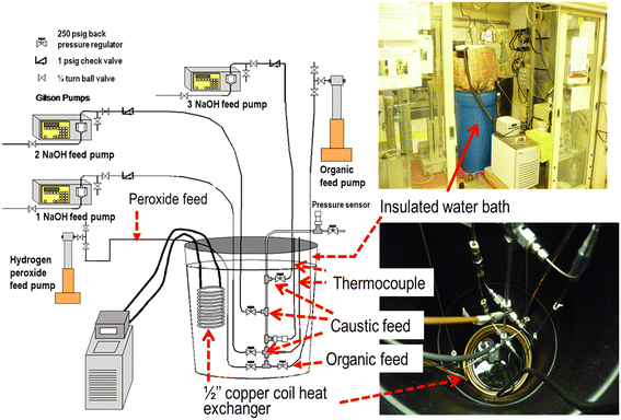
To validate the reactor design, a simple experimental set-up comprising a ¼ inch diameter, 24 inch long stainless steel tube immersed in a 26 gallon water bath was set up in a ventilated enclosure [Fig. 1]. The water bath was well insulated with 3.5 inch fiber glass insulation and fitted with a Total Pond MD11300 submersible pump (West Palm Beach, FL) to improve convection. Further, the water bath was placed in a 55 gallon secondary containment for ensuring process safety. A ½ inch copper coil, connected to a heat exchanger (Neslab RTE 10 ThermoScientific, Waltham MA) was immersed in the water bath to maintain the reactor at 50 °C. Premixed organic feed was fed at the reactor bottom through a 1/16th inch tube using a 500D Isco syringe pump (Teledyne Isco, Lincoln NE) while the oxidizer feed was pumped through a 1/16th inch passivated stainless steel tube using a 500D Isco syringe pump set at a maximum pressure of 500 psi. All the feed lines were maintained at 250 psi using a back pressure regulator (Model P-788, Upchurch Scientific, Oakharbor WA). Since maintaining the reactor pH in the range of 9–11 was critical to sustain the reaction, caustic solution was fed at three locations along the reactor length through a 1/16th inch tube using 3 Gilson pumps (Model 305). The process control was not automated and the reactor temperature was monitored using a type E thermocouple (Wika Instruments, Lawrenceville GA). The reactor pressure was maintained at nearly 30 psi using a series C fixed cracking pressure check valve (Swagelok, Cleveland OH) located at the reactor exit and was monitored using a 0–50 psi pressure transmitter (Omega Engineering, Stamford CT).Process safety
A key aspect of industrial process design and scale-up is the emphasis on design safety at the laboratory scale that can be leveraged at the pilot and commercial scale. Since this chemistry uses hydrogen peroxide, which can undergo different types of reactions based on decomposition, redox reactions, and reactions with organic materials, surface passivation strategies were developed. Importantly, the self-accelerated decomposition temperature for 35% hydrogen peroxide is 79 °C. Hence, to ensure process safety, the reactor surface was passivated with 35% nitric acid for 24 hours followed by a thorough rinse with deionized water to oxidize the metal surface and prevent any accelerated thermal decomposition.| H2O2(l) → H2O(l) + ½O2(g) (98 kJ per mol H2O2) | (2) |
Phase behavior of the reaction system
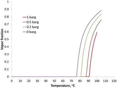
As mentioned earlier, hydrogen peroxide has a tendency to decompose, resulting in pressure build up. Specifically, the decomposition is accelerated at high pH in the presence of the caustic solution.5 Further, the two-phase formation could result in mass transfer limitations, resulting in lower feed conversion. To understand the phase behavior of the system, flash simulations were conducted in Aspen using the ELECNRTL equation of state to assess the vapor fraction in the reactor under operating conditions [Fig. 2]. Importantly, increasing the reactor pressure from 0 to 0.2 barg for a reactor feed with 4 wt% caustic solution favorably increased the feed vaporization temperature from 76 °C to 81 °C. Hence the reactor was operated at an elevated pressure to prevent any feed vaporization and thus a two-phase operation.Adiabatic temperature increase
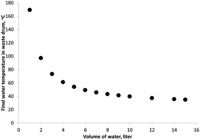
Adiabatic temperature increase for the waste drum, assuming no reaction in the reactor, was also estimated to determine the amount of heat quenching medium necessary in the waste drum over a typical operating day. As shown in Fig. 3, a minimum of 10 liters of water in the waste drum was necessary to quench any temperature rise due to the exothermic reaction, as well as peroxide decomposition.Operating procedure
To begin a run sequence, the water bath was first heated by setting the chiller pump for the constant temperature bath to 50 °C. Once the bath temperature reached the desired set point, premixed organic feed was pumped through the reactor using an Isco 500D syringe pump. Hydrogen peroxide solution (35 wt% technical grade, Aqua Solutions Deerpark, TX) was then flowed through the reactor through multiple feed points and feed samples were analyzed to ensure a steady flow through the reactor. Finally, 1 N sodium hydroxide (La-Mar-Ka Inc. Baton Rouge, LA) was pumped through the reactor at the desired flow rate and the reaction was monitored for temperature and pressure. Reaction samples were collected after nearly 30 minutes of introduction of sodium hydroxide and analyzed for residual hydrogen peroxide and pH. Samples were then periodically collected for up to 2 hours and analyzed for hydrogen peroxide conversion. At the end of the run, the caustic solution and hydrogen peroxide flow were stopped, heating to the water bath was shut off and the reactor was flushed with methanol to clean the reactor lines. To monitor the reaction selectivity, the products were analyzed for unreacted hydrogen peroxide using a titration method (Metrohm Model 802 Titrando, Herisau Switzerland) pH, and gas chromatography (Agilent-6890 Series) for compositional analysis.Results and discussion
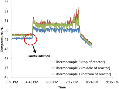
The driver for evaluating a continuous process using a tubular reactor was the potential reduction in residence time at comparable conversion and selectivity. Fig. 4 shows a typical temperature time profile for the reactor after caustic solution addition along the reactor length. Expectedly, addition of caustic solution leads to a temperature increase due to exothermic reactions. However, the high surface area to volume ratio of 764 (Table 1) for this reactor design enhances heat losses due to convection and allows better thermal management for continuous hydrogen peroxide flow.| H2O2 solution concentration (wt%) | 35 |
| NaOH/H2O2 mole ratio | 0.020 |
| NaOH solution concentration (wt%) | 4 |
| Target temperature (°C) | 45–50 |
| Tube length (inches) | 24 |
| Tube internal diameter (inches) | 0.21 |
| Target residence time (min) | 15 |
| Reactor surface area to volume (m2 m−3) | 764 |
| Organic feed flow (ml min−1) | 0.69 |
| H2O2 flow (ml min−1) | 0.14 |
For feed conditions described in Table 1, conversion up to 86% with a selectivity close to 46% was achieved in 15 minutes. Further, this data compared well with the Aspen model predictions as well as batch reactor data for a 15 minute residence time. Note that for the Aspen model predictions, the reactor was simulated as three consecutive plug flow reactors with multiple feed points. The system was allowed to reach a steady state up to 135 minutes before sampling. As mentioned earlier, the system pH plays a critical role in reaction kinetics with optimal reaction rates achieved at pH values between 10.0–10.5. For the batch run data, pH was continuously monitored and controlled to maintain the pH in the range of 9–11 by controlling the caustic feed in the system. Since the continuous reactor was not equipped with online pH control, it was not possible to monitor the extent of reaction and it is quite likely that the caustic concentration varied along the reactor length. This difference in caustic concentration profile may explain the slightly higher feed conversion obtained for the batch system than that for the continuous run. Notably, results as shown in Table 2 indicate up to a 20-fold decrease in the residence time from 5–6 hours to 15 minutes with a comparable feed conversion of 86% and similar product composition. This improved performance can be attributed to the continuous process with better thermal management due to efficient convective heat transfer. Specifically, for a reactor surface area to volume ratio of nearly 765 m2 m−3, a higher convective heat transfer is expected leading to tighter reactor temperature control, and thus enabling a higher hydrogen peroxide flow rate than that feasible in a batch process. Further, the product obtained using continuous processing was compositionally similar to the batch reactor product, as confirmed by GC analysis.
| Time, min | Conversion | Reaction selectivity | |
|---|---|---|---|
| Aspen model | 14.3 | 88% | 42% |
| Continuous reactor | 15 | 86% | 46% |
| Batch data | 300 | 94% | 41% |
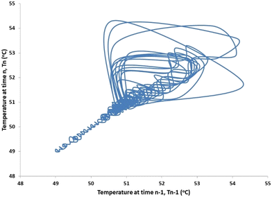
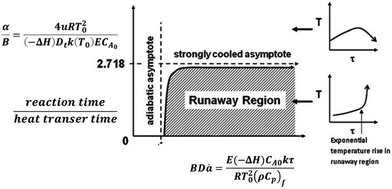
To increase the conversion beyond 90%, the residence time of the feed was doubled by increasing the reactor length to 48 inches. Further, based on Aspen model estimations, the caustic feed was increased up to 0.06 ml min−1 as well as the feed locations were changed to 1/3 and 2/3 the reactor length to ensure the desirable pH along the reactor length. However, comparable feed conversion of 87% was observed despite an increased caustic flow rate. A closer look at the temperature profile indicates temperature fluctuations at the first caustic feed point [Fig. 5]. A comparison of the time delay embedding plot for the reactor temperature [Fig. 6] with the typical plot for periodic oscillations indicates that the fluctuations are deterministic, but not periodic.6 For exothermic reactions, the reaction runaway regime is predicted by the ratio of the heat removal term α to the dimensionless Zeldovich number, B and the product of B and the Damkohler number, Da.7 For a tubular reactor, B and α are expressed as shown in eqn (3) and (4).
 | (3) |
 | (4) |
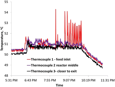 | ||
| Fig. 5 Increased temperature fluctuations near the feed inlet increased the caustic flow rate of 0.06 ml min−1. | ||
| Reaction activation energy | E a | kJ mol−1 | 33.1 |
| Pre-exponent factor | K 0 | min−1 | 19![[thin space (1/6-em)]](https://www.rsc.org/images/entities/char_2009.gif) 669 669 |
| Heat capacity of reactants | C p | J Kg−1 K−1 | 2512 |
| Heat of reaction/mol | ΔH | J mol−1 | −602![[thin space (1/6-em)]](https://www.rsc.org/images/entities/char_2009.gif) 899 899 |
| Mass fraction of limiting reactant | ω 0 | 0.12 | |
| Overall heat transfer coefficient of tubular reactor | U | W m−2 K−1 | 150 |
| Heat transfer area | A | m2 | 0.024 |
| Reaction temperature | T 0 | K | 323.15 |
| Gas constant | R g | J mol−1 K−1 | 8.31 |
| Reaction fluid in PFR | m | Kg | 0.0024 |
| Rate constant at T0 | k(T0) | s−1 | 0.00147 |
| Fluid density | ρ | Kg m−3 | 1000 |
| Reactant inlet concentration | F Ao | mol m−3 | 921.66 |
| ρ × Cp | J m−3 K−1 | 2![[thin space (1/6-em)]](https://www.rsc.org/images/entities/char_2009.gif) 512 512![[thin space (1/6-em)]](https://www.rsc.org/images/entities/char_2009.gif) 080 080 |
|
| Reactor diameter | D t | M | 0.0063 |
| Reactor length | L | M | 1.22 |
| Residence time | L/Vz | s | 900 |
| Zeldovich number | B | 8.43 | |
| Dimensionless external heat transfer coefficient | α | 25 | |
| Damkohler number | Da | 1.3 | |
| α/B | 3 |
(a) Peroxide decomposition combined with local cooling due to feed evaporation
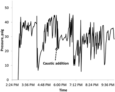
Peroxide decomposition is sensitive to pH and is accelerated at high pH.5 In the case of caustic feed fluctuations, peroxide decomposition may have occurred leading to local hot spots with simultaneous evaporation of methanol feed due to pressure fluctuations [Fig. 8], leading to cooling. Thus the temperature did not increase indefinitely but resulted in oscillations.(b) Generation of hot spots due to insufficient convection
For a ¼ inch tube operating close to the runaway regime, it is quite likely that the transverse heat convection was not fast enough leading to local hot spots and peroxide decomposition. However, since the reactor was not in the runaway mode, the temperature increase was not indefinite and the convective heat loss over time may have resulted in relatively small temperature oscillations.The stable operation shown in Fig. 4 indicates that our design criterion for heat removal and near isothermal operation is successful. Indeed, we obtained good selectivity and conversion suitable for commercialization and removed the heat generated by the reaction with an acceptable pressure drop.
Further increase in the caustic feed rate (corresponding to a higher production rate) causes aperiodic oscillations in temperature as shown in Fig. 5. This dynamic behavior indicates an approach to the ignition point. Note, however, that the amplitude of oscillation is small, well below the adiabatic temperature rise. This again indicates that the reactor design is successful.
The dynamic behavior shown in Fig. 5 deserves further comment. Jensen and Ray8 presented a bifurcation analysis of a cooled tubular reactor with an exothermic reaction. They showed that the steady-state bifurcations of a cooled tubular reactor are similar to that of a cooled CSTR; in fact, they are identical for a small Pe number. In their paper, the phase diagram of classification of the dynamic behavior of the CSTR in the parameter space B-β shows only 3 regions in which oscillations appear on the extinguished branch. In all three cases a Hopf bifurcation appears “close” to the ignition point (or turning point, in the language of their paper). We expect the extinguished branch will change from a stable node to a stable focus before the Hopf bifurcation as it does in a cooled CSTR.9 A stable focus will be susceptible to small perturbations (noise), and will produce transient oscillations in response, as shown in Fig. 5 and 6 of this work. Bursting of the type shown in Fig. 5 and 6 are often observed in codimension-two bifurcations, which may occur by a homoclinic connection of a saddle-node with a focus or limit cycle;10 a Shilnikov bifurcation. Oscillatory behavior is an indication of operation close to the ignition point (a saddle-node or limit point bifurcation). This region of sensitivity lies just above the strongly cooled asymptote shown in Fig. 7. The detection of oscillatory behavior provides an early warning of incipient ignition. In this case the present reactor design was sufficient to control the amplitude of the temperature oscillations to less than 5 °C. The phase portrait shown in Fig. 6 is characteristic of a Shilnikov bifurcation; i.e., extremely small amplitude oscillations with occasional bursts of larger amplitude reported by Shilnikov et al.11
These insights guide the reactor design and process scale-up for continuous synthesis and underscore the importance of fundamental analysis for the design of safe and efficient processes at the industrial scale. Notably, the team evaluated reactor design options with associated process scale-up estimations. Successful scale-up of this design would rely on scale-up by replication instead of typical scale out used in conventional PFR or CSTRs. This attractive feature for micro- and meso-reactors was one strong factor in considering this approach for this chemistry. Thus for scaling up this chemistry, one can envision using the throughput for a single reactor and for a given production capacity, estimate the total number of tubes needed. For example, initial design estimates indicate a tubular reactor with roughly 1000 tubes, 0.25 inch in diameter and 20 feet long for 99% feed conversion and 98% product selectivity for 1 kTA. It is important to note that to ensure that the reactor is not operating under runaway conditions, the overall convective heat transfer coefficient, U, needs to be optimized by the appropriate choice of coolant as well as coolant velocity.
Summary and conclusions
This article focused on process and reactor design considerations for continuous processing of specialty resins at the industrial scale. The current batch process involves exothermic reactions at 50 °C and atmospheric pressure resulting in an adiabatic temperature increase up to 250 °C for a reactor feed with up to 13 wt% of the limiting reactant, necessitating controlled peroxide addition and resulting in a longer processing time up to 6 hours. Further, the longer residence time adversely affects the reaction selectivity, resulting in undesirable solvolysis and polymerization reactions. Using reactor design principles, a continuous process using a ¼ inch tubular reactor was investigated. Initial results indicate up to 12-fold decrease in the residence time from 6 hours to 30 minutes with a comparable feed conversion of 87% and similar product composition. Greater than 90% conversion could not be achieved in the current reactor configuration and associated reactor runaway analysis suggests feed decomposition due to pressure fluctuations or insufficient caustic feed in the reactor. The analysis highlights the need for designing a reactor with better pressure control using a back pressure regulator and choosing a smaller diameter tube. These insights ultimately guided the reactor design and process scale-up for continuous synthesis of this chemistry. This study underscores the importance of applying fundamental reactor engineering principles and analysis for the design of safe and efficient processes at the industrial scale.Data availability
The authors have provided relevant information pertaining data analysis and the overall approach to design selection in the manuscript and associated references are available to download at respective journal sites.Conflicts of interest
There are no conflicts to declare.References
- K. F. Jensen, AIChE J., 2017, 63, 858–869 CrossRef CAS
.
- L. Thomas and M. Ramachandra, Mater. Today: Proc., 2018, 5, 2635–2640 CAS
.
- P. Watts and C. Wiles, J. Chem. Res., 2012, 36, 181–193 CrossRef CAS
.
- V. Balakotaiah and D. H. West, Chem. Eng. Sci., 2002, 57, 1269–1286 CrossRef CAS
.
- Hydrogen Peroxide Bulk Storage Guideline, 2001 Search PubMed.
- I. G. Kevrekidis, L. D. Schmidt and R. Aris, Chem. Eng. Sci., 1986, 41, 1263–1276 CrossRef CAS
.
- V. Balakotaiah, D. Kodra and D. Nguyen, Chem. Eng. Sci., 1995, 50, 1149–1171 CrossRef CAS
.
- K. F. Jensen and W. H. Ray, Chem. Eng. Sci., 1982, 37, 199–222 CrossRef CAS
.
- A. R. Champneys and Y. A. Kuznetsov, Int. J. Bifurc. Chaos, 1994, 04, 785–822 CrossRef
.
- A. Uppal, W. H. Ray and A. B. Poore, Chem. Eng. Sci., 1974, 29, 967–985 CrossRef CAS
.
- A. Shilnikov, L. Shilnikov and D. Turaev, Mosc. Math. J., 2005, 5, 269–282 CrossRef
.
Footnote |
| † Retired from Dow Chemical Company. |
| This journal is © The Royal Society of Chemistry 2024 |

