 Open Access Article
Highly modular PDMS microwave-microfluidic chip reactor for MAOS applications†
Laura Y.
Vázquez-Amaya‡
 a,
Matko
Martinic‡
b,
Bart
Nauwelaers
b,
Erik V.
Van der Eycken
 ad,
Tomislav
Markovic
bc and
Upendra K.
Sharma
 *a
*a
aLaboratory for Organic & Microwave-Assisted Chemistry (LOMAC), Department of Chemistry, University of Leuven (KU Leuven), Celestijnenlaan 200F, B-3001 Leuven, Belgium. E-mail: usharma81@gmail.com; upendrakumar.sharma@kuleuven.be
bDivision WaveCoRE, Department of Electrical Engineering (ESAT), KU Leuven, Kasteelpark Arenberg 10, Box 2444, 3001 Leuven, Belgium
cFaculty of Electrical Engineering and Computing, University of Zagreb, Unska 3, 10000, Zagreb, Croatia
dPeople's Friendship University of Russia (RUDN University), Miklukho-Maklaya Street 6, RU-117198 Moscow, Russia
First published on 2nd May 2024
Abstract
In this work, we introduce a microfluidic chip reactor based on a complementary split ring resonator (CSRR) for conducting microscale organic reactions with the aid of microwave irradiation. This microwave-microfluidic chip reactor (μw-μf-CR) is easy to assemble and highly customizable, featuring interchangeable flow cells fabricated on inexpensive PDMS, providing high levels of versatility in terms of manufacturing and design. Three flow cells were designed and explored, offering internal volumes ranging from 2.82 to 6.48 μL and accommodating flow rates between 5 and 8 μL min−1. This allows the reaction to be irradiated within a timeframe spanning from seconds to minutes. Remarkably, our setup design bears the potential to operate across a broad range of frequencies (around 2 or 6–12 GHz). Moreover, it provides controllable and efficient heating, reaching temperatures up to 120 °C within seconds with a maximum low input power of 4.4 W. Simulations showed an excellent homogeneous heat distribution throughout the flow cell. The applicability of the μw-μf-CR was demonstrated in several organic reactions, where good yields and short reactions time were observed.
1. Introduction
The application of microfluidic technology to chemical synthesis (μSyn) offers a new platform to enhance the performance of organic reactions. In contrast to conventional batch techniques, μSyn normally involves confined flowing liquids in miniature microreactors such as microtubes, microchannels, or microcapsules, which provides high rates of mixing, heat/mass transfer and a precise control down to nm and pL scales.1 Additionally, the versatility of microreactor design and fabrication broadens its applicability by improving efficiency, controllability, and safety.2 Microreactors are constantly regarded as a green technology as they promote the development of a sustainable synthetic chemistry with small quantities of reagents/solvents, short residence time and low energy consumption, which leads to minimal waste of resources.2,3 In the continuous search for the ideal sustainable reactor, numerous enhancing technologies for process intensification in continuous flow have been adapted to microreactors including photochemistry, electrochemistry and MW-irradiation.4,5 This latter has found interesting applications in organic synthesis, since the small diameter of microreactors is ideal for the use of MW heating, as it solves the problem of the limited penetration depth of microwave irradiation, while addressing new scalability opportunities.6,7 To date, microwave heating devices commonly employed in μSyn predominantly rely on high-power magnetrons with waveguides or resonant cavities operating at 2.45 GHz (ISM frequency band).8,9 However, for many organic solvents, 2.45 GHz does not correspond to the frequency with the maximum dielectric loss, resulting in a non-optimal dielectric heating.10 In this context, the development of flow microwave reactors with access to a broader and tunable frequency range that would allow for more efficient coupling of microwave energy and therefore optimum heating are desirable.11Additionally, in recent years an emerging subdomain known as microwave-microfluidics has gained prominence. This field involves the integration of microwave circuits with miniaturized channels, resulting in microfluidic devices operating within the nano- to microliter scale, and capable of continuous-microwave irradiation. Such devices are typically characterized by the use of a broader frequency range spanning from 2.45 GHz to 25 GHz and by fast and efficient microwave heating using low-power inputs.12 Although this rapidly advancing field has gained widespread use in chemical sensing, heating of liquids, and biology,13–15 examples of its applications in chemical synthesis remain isolated. The latter, despite the fact that the synergistic use of microwave heating and microfluidics could ultimately lead to high reaction rates and yields.16,17
In this context, a variety of technologies have been integrated into these systems to enable microwave heating including planar heaters, interdigitated capacitors, and coupled lines.12 Particularly noteworthy is the complementary split ring resonator (CSRR) microwave structure, which is a planar resonant structure consisting of a microstrip transmission line with a capacitively coupled defected ground plane. This structure modifies characteristic impedance and dispersion of a transmission line.15,18 CSRRs have attracted significant attention due to its ability to produce concentrated electric fields (E-field) alongside high sensitivity and ease of manufacturing. As a result, it has been recognized as both a highly sensitive dielectric sensor and an efficient microwave heater.15
In order to unlock the potential of microwave-microfluidics in microwave-assisted organic synthesis (MAOS), we became interested in developing a μw-μf-CR based on a CSRR with controllable microwave heating. The CSRR was chosen over other resonant structures previously used for flow MAOS due to its E-field distribution perpendicular to its surface, which results in increased temperature uniformity within the sample,15 and large surface area to accommodate the flow cell. In addition, the working frequency of the CSRRs is easily changed by modifying its dimensions while keeping the same footprint area, contributing to the modularity of our design. The resulting MW reactor exhibits high efficiency, excellent temperature uniformity, and precise temperature readings as shown by temperature-dependent Rhodamine B measurements (see ESI†). These features are crucial for fast and reproducible experiments. Furthermore, the high modularity of our reactor and setup enables easy assembly and interchangeability of various elements, including flow cells and microwave heaters working at varying frequencies. Our developed technology constitutes a substantial advancement towards tailored and more efficient microwave heating methodologies.
2. Materials and methods
MW heater and flow cell design
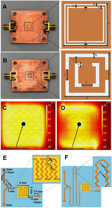
In this work, CSRRs are used as microwave heaters, which are fabricated on a Rogers RO4003 substrate (ε′ = 3.55, tan![[thin space (1/6-em)]](https://www.rsc.org/images/entities/char_2009.gif) δ = 0.002) with a 0.51 mm thickness and 35 μm copper cladding. Microwaves are produced by a signal generator, amplified using a power amplifier, and directed to a microstrip coupled to the CSRR. Upon supplying electromagnetic waves at a specific frequency, a resonance occurs due to the CSRR structure. Such resonance induces a perpendicular E-field proportional to the applied microwave power over the CSRR. This field penetrates the liquid within the microchannels, leading to fast and highly efficient microwave heating. In order to examine the impact of higher frequencies on the outcome of chemical processes, two CSRRs were manufactured with the ability to operate at around 2 and 8 GHz when loaded with a polydimethylsiloxane (PDMS) flow cell. The frequency spacing between the two is believed to be large enough to observe any frequency related influence on the outcome of chemical reactions. Both CSRRs include a large central patch that accommodates the flow cell and ensures a consistent temperature distribution, while working at specified frequencies.15 The final dimensions are A = 6 mm and B = C = D = E = F = 0.2 mm for a MW heater working at around 2 GHz and A = 6 mm, B = D = 0.5 mm, C = 0.8 mm, and E = F = 1.4 mm for a MW heater working at around 8 GHz (Fig. 1A and B). The width of a microstrip on the other side of the MW heater is 1.08 mm in both cases (see ESI†). To assess the temperature distribution during MW heating, a COMSOL MW heating simulation with the microfluidic channel filled with water and acetonitrile were conducted for the reactors working at around 2 GHz and 8 GHz, respectively (material properties used are listed in ESI†). The accuracy of the simulations was determined using the temperature dependant die Rhodamine B. The resulting profile shows an excellent temperature uniformity inside the microfluidic channel, and great agreement with COMSOL simulations (for more details see ESI†), with similar results obtained using other commonly used organic solvents (Fig. 1C and D). For accurate temperature measurements during the reactions, a thermocouple (RS PRO Type K, 0.076 mm) was inserted into the flow cell between the channels, with a thin layer of PDMS separating the reaction mixture and the sensor. The thin layer of PDMS between the temperature sensor and the channel, as seen in Fig. 1C and D, has no effect on the temperature readout, allowing for accurate temperature readings.
δ = 0.002) with a 0.51 mm thickness and 35 μm copper cladding. Microwaves are produced by a signal generator, amplified using a power amplifier, and directed to a microstrip coupled to the CSRR. Upon supplying electromagnetic waves at a specific frequency, a resonance occurs due to the CSRR structure. Such resonance induces a perpendicular E-field proportional to the applied microwave power over the CSRR. This field penetrates the liquid within the microchannels, leading to fast and highly efficient microwave heating. In order to examine the impact of higher frequencies on the outcome of chemical processes, two CSRRs were manufactured with the ability to operate at around 2 and 8 GHz when loaded with a polydimethylsiloxane (PDMS) flow cell. The frequency spacing between the two is believed to be large enough to observe any frequency related influence on the outcome of chemical reactions. Both CSRRs include a large central patch that accommodates the flow cell and ensures a consistent temperature distribution, while working at specified frequencies.15 The final dimensions are A = 6 mm and B = C = D = E = F = 0.2 mm for a MW heater working at around 2 GHz and A = 6 mm, B = D = 0.5 mm, C = 0.8 mm, and E = F = 1.4 mm for a MW heater working at around 8 GHz (Fig. 1A and B). The width of a microstrip on the other side of the MW heater is 1.08 mm in both cases (see ESI†). To assess the temperature distribution during MW heating, a COMSOL MW heating simulation with the microfluidic channel filled with water and acetonitrile were conducted for the reactors working at around 2 GHz and 8 GHz, respectively (material properties used are listed in ESI†). The accuracy of the simulations was determined using the temperature dependant die Rhodamine B. The resulting profile shows an excellent temperature uniformity inside the microfluidic channel, and great agreement with COMSOL simulations (for more details see ESI†), with similar results obtained using other commonly used organic solvents (Fig. 1C and D). For accurate temperature measurements during the reactions, a thermocouple (RS PRO Type K, 0.076 mm) was inserted into the flow cell between the channels, with a thin layer of PDMS separating the reaction mixture and the sensor. The thin layer of PDMS between the temperature sensor and the channel, as seen in Fig. 1C and D, has no effect on the temperature readout, allowing for accurate temperature readings.
Due to the laminar regime as a consequence of the low volume of the flow cells, zig-zag-shaped channels were incorporated to induce turbulent flow and promote efficient mixing.19 Three different flow cells were designed. In flow cell A, zig-zag channels were only incorporated in the reactor zone (Fig. 1E, 2.82 μL or 6.48 mL), while flow cell B features an additional mixing zone right before the reactor area (Fig. 1F). Dimensions of the designed flow cells are shown in Fig. 1E and F (for more details see ESI†).
Flow cell manufacturing
For this work, PDMS was chosen due to its low cost and fast prototyping. PDMS flow cells were manufactured by soft lithography using a 3D-printed mold. The flow cells consist of 2 inlets, a reactor area positioned on top of the CSRR, and an outlet. The channels are made as a zig-zag structure to promote mixing with a footprint smaller than CSRR's for increased temperature uniformity.19 A temperature sensor was precisely placed between the channels for temperature measurements. PDMS was prepared as recommended in the datasheet. For the curing process, the PDMS flow cell was allowed to cool down at room temperature for 12 h to ensure that all bubbles disappear, and then heated at 120 °C for 6 h until fully solidified. Finally, the flow cell was removed from the mold, inlets and outlets were punched with a 1.5 mm diameter puncher for PFA tubing to fit. A glass cover with 0.13 mm thickness was used to close the channels. For assembly, a non-permanent bonding method was used, in which the PDMS flow cell with glass cover sits on top of the MW-heater, the two pieces are sandwiched together with applied pressure using a laser-cut polymethyl methacrylate (PMMA) cover, positioner and support. The setup is tightly secured with 4 bolts and nuts (Fig. 2A and B). Chemicals and solvents are pumped through the system using syringe pumps and PFA tubing connected to the μw-μf-CR (for more details see ESI†). | ||
| Fig. 2 A) Schematic representation of the μw-μf-CR. B) Picture of the assembled μw-μf-CR seen from the side (top image) and the top (bottom image). | ||
Complete setup
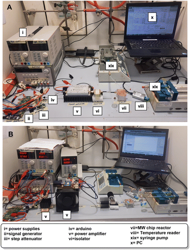
The complete setup is depicted in Fig. 3A and B. Before conducting reactions, the working frequency of the reactor loaded with reactants inside the flow cell is measured. The frequency is then entered into the signal generator to produce a MW signal for heating. Two setups are shown, with the first one working up to 2.5 GHz used in combination with the MW heater working at around 2 GHz and the second working between 6–12 GHz for experiments with the MW heater working at around 8 GHz. The setups are made to be similar with the possibility to change certain components to work at different frequencies. Both setups consist of a signal generator (ADF4355 or ADF4372, Analog Devices) connected to a step attenuator (HMC941ALP4E, Analog Devices) that is controlled with Arduino Nano to limit MW heating power and, with that, keeps the reaction temperature constant. A power amplifier (KU PA BB 233 BBA, Kuhne electronics or ZVA-183WA-S+, Minicircuits in combination with CMPA601C025F, Wolfspeed) is needed to increase the MW power to achieve the set temperature. Finally, the isolator (COI02040618G, Cernex or PE83CR1006, Pasternack) is connected to the reactor to prevent damaging the power amplifier. The whole setup is controlled using a PC with a proprietary application developed in MATLAB for easy temperature and frequency control. The temperature was read using a temperature reader (TC01, National Instruments) connected to the temperature sensor. To supply the setup with electrical energy, two or four power supplies were used depending on the heating frequency (Fig. 3A–C, for more details see ESI†).3. Results and discussion
With the developed technology in hand, the first step towards its validation involved testing its efficiency in heating organic solvents and eventually reaction mixtures. To do so, ethanol was injected into the flow cell and irradiated at a maximum heating power of 4.4 W. Pleasantly, we found that the temperature increased up to 120 °C in less than 10 s with a heating rate of 67 °C s−1 (Table 1, entry 5). The latter confirms that the solvent in the chip reactor can efficiently absorb microwave irradiation and reach high temperatures within seconds using minimal microwave power inputs. Similar measurements and excellent heating rates were obtained for other common organic solvents (Table 1).| Entry | Solvent | Heating rate (°C s−1) |
|---|---|---|
| 1 | DMF | 80 |
| 2 | DMA | 68 |
| 3 | Acetonitrile | 67 |
| 4 | Methanol | 50 |
| 5 | Ethanol | 67 |
| 6 | Acetone | 62 |
| 7 | THF | 58 |
| 8 | Ethyl acetate | 55 |
| 9 | Toluene | 52 |
Encouraged by these results, the next phase in the validation process involved assessing the efficacy of our μw-μf-CR in facilitating a reaction based on a literature MW procedure, serving as a benchmark for comparison. To begin with, the four-component Ugi reaction for the synthesis of arylboronic acid analogs was chosen.20 The reaction mixture, as described, underwent heating at 45 °C with a power input of 150 W for 30 min, resulting in the corresponding Ugi products in good to high yields. Owing to the intrinsic correlation between energy consumption and MW power generation, the production of high-power inputs invariably leads to increased energy usage (energy = power × time). The latter results in a significant waste of energy, particularly when the reaction is carried out at moderate temperature using large power inputs. In this context, our μw-μf-CR emerges as a more sustainable alternative. The narrow channels of the device facilitate reaching high temperatures with minimal microwave input power.
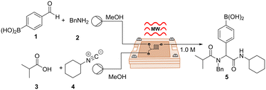
We started our investigation by using a two-inlet-one-outlet 6.48 μL flow cell. The premixed mixture of benzaldehyde 1 and benzylamine 2 was injected through one inlet, while a mixture of carboxylic acid 3 and isocyanide 4 was injected through a second inlet. The reaction mixture was continuously flowed at a combined flow rate of 10 μL min−1 (tR = 39 s), heated at 45 °C (2.01 GHz), and quenched upon exit. Interestingly, these conditions provided the desired product 5 in 24% yield (Table 2, entry 1). The latter illustrates that, despite the narrow channels of our device, which can be an issue with MW-microreactors,8 the reaction mixture was able to pick up enough microwave irradiation under flow conditions to undergo partial conversion. Increasing the temperature of the reaction afforded a slightly higher yield of 38% (Table 2, entry 2). Notably, the desired product was obtained in 70% yield simply by reducing the combined flow rate to 5 μL min−1 (tR = 78 s), most likely as a result of the reaction being exposed to irradiation for a longer period of time (Table 2, entry 3). Finally, increasing the temperature to 70 °C yielded an optimized 75% yield with a throughput of 0.23 mmol h−1 (Table 2, entry 4). Remarkably, the use of our μw-μf-CR allowed us to successfully obtain the desired compound with high yields and short reaction times by using a low microwave power input of 1 W. Furthermore, in contrast to the original report, we were able to work at higher temperatures, which likely also contributed to the acceleration of the reaction. The latter, due to the high levels of control when working at μL scale, even when handling pungent compounds. This contribution represents a further step towards odourless isocyanide chemistry.21
| Entry | Temperature, °C | Flow rate, μL min−1 | t R, s | 5 (%) |
|---|---|---|---|---|
| a All reactions were carried out using 1 (0.5 mmol), 2 (0.5 mmol, 1.1 equiv.), 3 (0.55 mmol, 1.1 equiv.), 4 (0.55 mmol, 1.1 equiv.), 1.0 M, 2.01 GHz, maximum available power 4.4 W, μw-μf-CR, flow cell A (6.48 μL). b GC-MS yields using 3,5,6-trimethoxybenzaldehyde as an internal standard. Isolated yields in brackets. | ||||
| 1 | 45 | 10 | 39 | 24 |
| 2 | 60 | 10 | 39 | 38 |
| 3 | 60 | 5 | 78 | 70 |
| 4 | 70 | 5 | 78 | 77(75) |
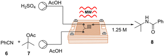
Following our successful validation experiments, we sought to explore and broaden the applicability of our μw-μf-CR in organic synthesis, therefore we chose a series of transformations. Since microreactors are particularly well suited for hazardous chemistry involving toxic or explosive reagents,22 we chose to explore an exothermic Ritter reaction, a potent method for synthesizing valuable N-alkyl amide products by combining alcohols and nitriles. Nonetheless, this reaction involves the use of harsh and strongly acidic reaction conditions, which on a large scale could lead to safety concerns. Our investigation was based on the procedure outlined by Wirth et al., who introduced the reaction in continuous flow using tert-butyl acetate as a cation source in a mixture of AcOH and H2SO4.23 The described reaction took place in a 200 μL PTFE microreactor equipped with a micromixer, heated to 45 °C, and maintained for a residence time of 6 min to afford the corresponding products in moderate to good yields.
In accordance with the original report, we opted for the two-inlet-one-outlet flow cell B (Fig. S1†), incorporating extra mixing elements for this transformation. It is worth noting that we were able to observe the formation of the desired product 8 even at a flow rate of 20 μL min−1, corresponding to a small residence time of 8.5 s (Table 3, entry 1). To ensure full conversion and to secure a high yield of 80%, it was essential to elevate the temperature to 60 °C and reduce the flow rate to 8 μL min−1 (Table 3, entry 4). It is noteworthy that, despite the seemingly minimal microliter volume of our reactor, the space–time yield (STY) for this transformation was slightly higher (0.170 mol h−1 mL) compared to the STY reported in the original study (0.104 mol h−1 mL).
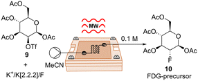
After confirming the ability of our reactor in handling exothermic reactions, we turned our attention to explore further applications. We directed our focus towards a fluorination reaction for the potential synthesis of radiotracers. These compounds find extensive application in positron emission tomography (PET), a robust molecular imaging technique applied in diagnosis and therapy control.24 Despite the high demand, the synthesis of radiotracers poses several challenges, including the rapid decay of radioisotopes, the high cost of precursors, and the generation of highly toxic byproducts. Due to these challenges, radiotracers are commonly produced in small quantities, on-demand, and preferably through rapid processes.25,26 In this scenario, the synthesis of radiotracers appeared to be an ideal challenge for our μw-μf-CR. As a proof-of-concept, we conducted the non-radioactive synthesis of the precursor of popular radiotracer 2-fluoro-2-deoxy-D-glucose (FDG). We commenced by assessing the compatibility of the reaction under microwave (MW) heating using a CEM discover reactor. To do so, a mixture of 9 and KF/K222/K2CO3 in anhydrous acetonitrile was heated at 70 °C with an input power of 50 W for 5 min. Pleasantly, the desired fluorinated product 10 was achieved with an 65% yield (Table 4, entry 1). Subsequently, we aimed to replicate this reaction in our μw-μf-CR. The premixed mixture of 9 and KF/K222/K2CO3 was introduced into the 2.82 μL flow cell A (Fig. S1†) and heated at 70 °C with a flow rate of 5 μL min−1 (tR = 34 s), resulting in the formation of desired compound 10 with a yield of 44% (Table 4, entry 2). By elevating the reaction temperature to 90 °C, we achieved the desired product in 61% yield (Table 4, entry 4). The obtained results, highlight the potential of our technology for the on-demand production of radiopharmaceuticals.27
| Entry | Reactor | T, °C | Flow rate, μL min−1 | t R, s | 10 (%) |
|---|---|---|---|---|---|
| a Reactions were carried out using 9 (0.1 mmol), Kryptofix® 222 (0.1 mmol, 1 equiv.), KF (0.07 mmol, 0.7 equiv.), 0.1 M, 2.0 GHz, maximum available power 4.4 W, μw-μf-CR, flow cell A (2.82 μL). b Same equivalents as a, reaction performed in CEM, 50 W, 2.45 GHz. c GC-MS yields using 3,5,6-trimethoxybenzaldehyde as an internal standard. Isolated yields in brackets. | |||||
| 1b | CEM | 70 | — | 5 min | 65 |
| 2 | μw-μf-CR | 70 | 5 | 34 | 44 |
| 3 | μw-μf-CR | 80 | 5 | 34 | 60 |
| 4 | μw-μf-CR | 90 | 5 | 34 | 63(61) |
| 5 | μw-μf-CR | 90 | 8 | 21 | 45 |
Furthermore, the impact of microreactors in drug discovery cannot be denied. The pharmaceutical industry consistently seeks the advancement of new technologies that can expedite the drug discovery process by swiftly generating small quantities of drug candidates for initial testing.28 Often these syntheses entail multistep processes, and given that amide bonds are ubiquitously present in active pharmaceutical ingredients (API), we envisioned a two-step reaction for the synthesis of secondary amides as the next challenge for our μw-μf-CR.
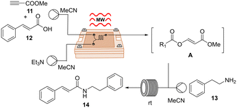
For this investigation, we took inspiration from the one-pot two-step direct amidation reaction of carboxylic acids as reported by Xu et al.29 Their protocol featured the in situ formation of an α-acyl enol ester A as an active intermediate, followed by nucleophilic acyl substitution by primary amines, resulting in the generation of various secondary amides in good to high yields. While the nucleophilic substitution was rapidly accomplished, the bottleneck in the reaction lies in the formation of intermediate A, which took up to 5 h in some cases. In this context, we became interested in advancing the two-step transformation in continuous flow and exploring the possibility of expediting the initial step of the reaction using our μw-μf-CR. If successful, this approach could potentially lead to the rapid synthesis of secondary amides within minutes. Given that the reaction was initially conducted in batch at room temperature, our initial goal involved evaluating its performance under MW irradiation using a CEM discover reactor. A mixture of cinnamic acid 12, methyl propiolate 11 and triethylamine in acetonitrile was irradiated at 50 °C and 50 W for 25 min. Following irradiation, TLC analysis revealed the complete consumption of the starting material and the formation of intermediate A. Then amine 13 was added, and the reaction mixture was stirred for an additional 10 min at room temperature, resulting in the desired secondary amide 14 in 85% yield (Table 5, entry 1).
| Entry | Reactor | T, °C | Flow rate, μL min−1 | t R | 14 (%) |
|---|---|---|---|---|---|
| a Reactions were carried out using 12 (0.1 mmol), Et3N (0.11 mmol, 1.1 equiv.), 11 (0.2 mmol, 2 equiv.), maximum available power 4.4 W, μw-μf-CR, flow cell A (6.48 μL), 2.04 GHz. b Same equivalents as a, reaction performed in CEM, 50 W, 2.45 GHz. c 1H NMR yields using 3,5,6-trimethoxybenzaldehyde as an internal standard. Isolated yields in brackets. | |||||
| 1b | CEM | 50 | — | s1: 25 min | 85 |
| s2: 10 min | |||||
| 2 | μw-μf-CR | 50 | s1: 10 | s1: 39 s | 30 |
| s2: 10 | s2: 10 min | ||||
| 3 | μw-μf-CR | 70 | s1: 10 | s1: 39 s | 57 |
| s2: 10 | s2: 10 min | ||||
| 4 | μw-μf-CR | 70 | s1: 8 | s1: 49 s | 69 |
| s2: 12 | s2: 10 min | ||||
| 5 | μw-μf-CR | 70 | s1: 5 | s1: 78 s | 83 |
| s2: 15 | s2: 10 min | ||||
| 6 | μw-μf-CR | 70 | s1: 5 | s1: 78 s | 91(87) |
| s2: 25 | s2: 7 min | ||||
The adaptation of the reaction to our μw-μf-CR proved to be straightforward and effective. For the first step, we utilized the two-inlet-one-outlet 6.48 μL flow cell A (Fig. S1†), while the second step was performed in a 200 μL PFA tubing reactor. Optimal conditions for the transformation were identified as a combined flow rate of 5 μL min−1 at 70 °C for the first step, paired with 30 μL min−1 for the second step, yielding the desired product 14 in an excellent 87% yield with a throughput of 0.043 mmol h−1 (Table 5, entry 6).
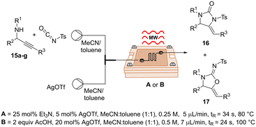
In addition, given the importance of frequency in microwave dielectric heating, several studies have been focused on its possible impact on the reaction outcome, in terms of yields, reaction rates, and product distribution.10,30,31 In the light of this, and since our μw-μf-CR have access to a broader range of frequencies, we decided to investigate this matter. For this, we selected a silver-catalysed cycloisomerization of propargylic ureas previously reported by our group.32 Remarkably, during the course of this study, we discovered that the introduction of a base or an acid into the reaction medium allowed for the selective formation of imidazolidin-2-ones 16 or oxazolidin-2-imines 17 using a silver catalyst (for additional details see ESI†). Following a rapid optimization of reaction conditions using our μw-μf-CR at 2.04 GHz, we successfully selectively obtained the desired imidazolidin-2-one 16a in 80% yield under protocol A, and oxazolidin-2-imines 17a with a yield of 81% under protocol B (Table 6, entry 1, for more details see ESI†). Once the reactions were fully optimized, the subsequent phase of our investigation involved conducting the reactions at a higher frequency. The Ag-catalyzed cycloisomerization reactions were carried out using our optimized conditions at 7.69 GHz. Nevertheless, there were no appreciable variations in yields or product ratios between the reactions carried out at 2.04 GHz and 7.69 GHz (Table 6, entry 1–2). This outcome could be rationalized by the fact that the impact of higher frequencies on the heating rates of organic solvents has been found to be more pronounced in non-polar solvents than in polar solvents, suggesting that nonpolar solvents could be more advantageous in organic reactions at higher MW frequencies.30
| Entry | 15 | R1 | R2 | R3 | Protocol | 16 (%) | 17 (%) |
|---|---|---|---|---|---|---|---|
| a All reactions were carried out on a 0.1 mmol scale, maximum available power 4.4 W, μw-μf-CR, flow cell A (2.82 μL), 2.04 GHz. b Reactions performed at 7.69 GHz. c Isolated yield. d 1H NMR yields using 3,5,6-trimethoxybenzaldehyde as an internal standard. | |||||||
| 1 | 15a | Bn | i-pr | Ph | A | 80 | 6d |
| B | 7d | 81 | |||||
| 2b | 15a | Bn | i-pr | Ph | A | 76 | 8d |
| B | 8d | 77 | |||||
| 3 | 15b | PMB | Pr | Ph | A | 73 | 9d |
| B | 5d | 78 | |||||
| 4 | 15c | PMB | p-FC6H4 | p-(tBu)C6H4 | A | 78 | 7d |
| B | nd | 78 | |||||
| 5 | 15d | Bn | Ph | Thiophen-3-yl | A | 77 | 15d |
| B | nd | 85 | |||||
| 6 | 15e | Bn | Naphthyl | Ph | A | 85 | nd |
| B | nd | 88 | |||||
| 7 | 15f | Bn | Ph | p-(CH3)C6H4 | A | 70 | 5d |
| B | 12d | 79 | |||||
Lastly, a series of imidazolidin-2-ones 16 and oxazolidin-2-imines 17 were synthesized in good yields and selectivity, demonstrating the potential of our reactor in the manufacture of small libraries of compounds (Table 6).
4. Conclusions
In conclusion, we have successfully developed a microwave microfluidic chip reactor (μw-μf-CR) with controllable and efficient heating based on a complementary split ring resonator (CSRR). The developed technology features high levels of modularity enabling easy assembly and interchangeability of various elements, including PDMS flow cells and microwave heaters. Remarkably, our setup design bears the potential to operate in a broad range of frequencies and can reach temperatures up to 120 °C within seconds using a maximum available input power of 4.4 W. In addition, excellent heating rates for a variety of solvents were obtained. The μw-μf-CR demonstrated applicability in several organic transformations, including an exothermic reaction, fluorination, and a two-step amidation. The desired products were obtained in high yields and short residence times, albeit optimal results required the application of low flow rates. Despite the seemingly minimal microliter volume of our reactor, modest throughputs of up to 0.48 mmol h−1 were achieved. Strategies to increase the volume and thus the throughput of our microreactors are being investigated. Moreover, we briefly studied the influence of the microwave frequency on a Ag-catalyzed cycloisomerization reaction; nevertheless, no significant variations were observed between the reactions performed at 2.04 GHz and 7.69 GHz. Future studies in our laboratory aim to explore the frequency effect further, particularly in reactions involving non-polar solvents. Finally, our μw-μf-CR represents a significant advancement towards fast, tailored and efficient microwave heating methodologies in the field of microfluidics, thus bringing new and exciting opportunities to μSyn.Author contributions
Study conception and design U. K. S. and T. M.; microwave heater design, M. M.; setup design and control, M. M., T. M., B. N.; flow cell design and manufacturing M. M.; simulations M. M.; temperature, frequency and power measurements M. M. and L. Y. V.-A.; spectroscopic studies and experiments L. Y. V.-A; writing – original draft preparation M. M. and L. Y. V.-A.; writing – review and editing U. K. S., T. M., E. V. V. D. E., and B. N.; supervision U. K. S, T. M., E. V. V. D. E. and B. N. All authors have read and agreed to the published version of the manuscript.Conflicts of interest
There are no conflicts to declare.Acknowledgements
The authors are thankful to CDE at ESAT, KU Leuven, for acquiring the components and developing PCBs. Thanks to FabLab, Leuven, for 3D printing molds used for PDMS flow cell manufacturing. Thanks to Wolfspeed for providing a sample of the power amplifier used for MW heating. L. Y. V.-A. and M.M. are thankful to BOF-IDN/20/014 project for a PhD scholarship (practical work and writing). The publication has been prepared with the support of the “RUDN University Strategic Academic Leadership Program” (recipient E. V. V. d. E.: writing and supervision). E. V. V. d. E. is thankful to the FWO for financial support via WOG W000520N (writing and supervision). This research was supported by the Research Foundation Flanders (FWO) through infrastructure grants I002720N and I001920N (recipient E. V. V. d. E.: writing and supervision).Notes and references
- Y. Liu and X. Jiang, Lab Chip, 2017, 17, 3960–3978 RSC
.
- K. S. Elvira, X. C. I. Solvas, R. C. R. Wootton and A. J. de Mello, Nat. Chem., 2013, 5, 905–915 CrossRef CAS PubMed
.
- K. F. Jensen, AIChE J., 2017, 63, 858–869 CrossRef CAS
.
- J. Wegner, S. Ceylan and A. Kirschning, Chem. Commun., 2011, 47, 4583 RSC
.
- L. Y. Vázquez-Amaya, G. A. Coppola, E. V. Van der Eycken and U. K. Sharma, Chimia, 2023, 77, 327 CrossRef PubMed
.
- G. Grillo, P. Cintas, M. Colia, E. C. Gaudino and G. Cravotto, Front. Chem. Eng., 2022, 4, 966451 CrossRef
.
- J. Wegner, S. Ceylan and A. Kirschning, Adv. Synth. Catal., 2012, 354, 17–57 CrossRef CAS
.
- E. Comer and M. G. Organ, J. Am. Chem. Soc., 2005, 127, 8160–8167 CrossRef CAS PubMed
.
- T. N. Glasnov and C. O. Kappe, Macromol. Rapid Commun., 2007, 28, 395–410 CrossRef CAS
.
- G. P. Lewis, S. R. Wylie, A. Shaw, A. I. Al-Shamma'a, D. Phipps, R. Alkhaddar and G. Bond, J. Phys.: Conf. Ser., 2007, 76, 012058 CrossRef
.
- J. P. Barham, E. Koyama, Y. Norikane, N. Ohneda and T. Yoshimura, Chem. Rec., 2019, 19, 188–203 CrossRef CAS PubMed
.
- T. Markovic and B. Nauwelaers, in 2022 IEEE MTT-S International Microwave Biomedical Conference (IMBioC), IEEE, 2022, pp. 28–30 Search PubMed.
- A. Tamra, D. Dubuc, M.-P. Rols and K. Grenier, IEEE Trans. Microwave Theory Tech., 2017, 65, 3512–3518 Search PubMed
.
- J. Bao, S. Yan, T. Markovic, I. Ocket, D. Kil, L. Brancato, R. Puers and B. Nauwelaers, IEEE Sens. Lett., 2019, 3, 1–4 Search PubMed
.
- T. Markovic, G. Maenhout, M. Martinic and B. Nauwelaers, Chemosensors, 2021, 9, 184 CrossRef CAS
.
- Y. Utsumi, A. Yamaguchi, T. Matsumura-Inoue and M. Kishihara, Sens. Actuators, B, 2017, 242, 384–388 CrossRef CAS
.
- R. Tanaka, T. Nakano, K. Fujitani, M. Kishihara, A. Yamaguchi and Y. Utsumi, Jpn. J. Appl. Phys., 2023, 62, SG1027 CrossRef
.
- J. D. Baena, J. Bonache, F. Martin, R. M. Sillero, F. Falcone, T. Lopetegi, M. A. G. Laso, J. Garcia-Garcia, I. Gil, M. F. Portillo and M. Sorolla, IEEE Trans. Microwave Theory Tech., 2005, 53, 1451–1461 Search PubMed
.
- W. Jeon and C. B. Shin, Chem. Eng. J., 2009, 152, 575–582 CrossRef CAS
.
- R.-C. Lian, M.-H. Lin, P.-H. Liao, J.-J. Fu, M.-J. Wu, Y.-C. Wu, F.-R. Chang, C.-C. Wu and P.-S. Pan, Tetrahedron, 2014, 70, 1800–1804 CrossRef CAS
.
- S. Chen, M. Oliva, L. Van Meervelt, E. V. Van der Eycken and U. K. Sharma, Adv. Synth. Catal., 2021, 363, 3220–3226 CrossRef CAS
.
- J. Yoshida, A. Nagaki and T. Yamada, Chem. – Eur. J., 2008, 14, 7450–7459 CrossRef CAS PubMed
.
- L. Audiger, K. Watts, S. C. Elmore, R. I. Robinson and T. Wirth, ChemSusChem, 2012, 5, 257–260 CrossRef CAS PubMed
.
- K. Serdons, A. Verbruggen and G. M. Bormans, Methods, 2009, 48, 104–111 CrossRef CAS PubMed
.
- F. Menzel, J. Cotton, T. Klein, A. Maurer, T. Ziegler and J. M. Neumaier, J. Flow Chem., 2023, 13, 247–256 CrossRef CAS
.
- Y. Fu, H. Helbert, N. A. Simeth, S. Crespi, G. B. Spoelstra, J. M. van Dijl, M. van Oosten, L. R. Nazario, D. van der Born, G. Luurtsema, W. Szymanski, P. H. Elsinga and B. L. Feringa, J. Am. Chem. Soc., 2021, 143, 10041–10047 CrossRef CAS PubMed
.
- L. Fernandez-Maza, B. Salvador, D. Orta, A. Corral and A. Luque, Microfluid. Nanofluid., 2019, 23, 109 CrossRef
.
- B. Gutmann, D. Cantillo and C. O. Kappe, Angew. Chem., Int. Ed., 2015, 54, 6688–6728 CrossRef CAS PubMed
.
- X. Xu, H. Feng, L. Huang and X. Liu, J. Org. Chem., 2018, 83, 7962–7969 CrossRef CAS PubMed
.
- S. Horikoshi and N. Serpone, Mini-Rev. Org. Chem., 2011, 8, 299–305 CrossRef CAS
.
- L. D. Conde and S. L. Suib, J. Phys. Chem. B, 2003, 107, 3663–3670 CrossRef CAS
.
- O. P. Pereshivko, V. A. Peshkov, J. Jacobs, L. Van Meervelt and E. V. Van der Eycken, Adv Synth Catal, 2013, 355, 781–789 CrossRef CAS
.
Footnotes |
| † Electronic supplementary information (ESI) available. See DOI: https://doi.org/10.1039/d4re00186a |
| ‡ L. Y. V.-A and M. M. contributed equally and share first authorship. |
| This journal is © The Royal Society of Chemistry 2024 |

