DOI:
10.1039/D4SE00056K
(Review Article)
Sustainable Energy Fuels, 2024,
8, 1872-1917
Design and development of nanostructured photocatalysts for large-scale solar green hydrogen generation
Received
12th January 2024
, Accepted 11th March 2024
First published on 19th March 2024
Abstract
The production of clean hydrogen through artificial photosynthesis is the most intriguing research topic that offers hope for meeting the world's energy demands. The evolution of green hydrogen via visible light-driven photocatalysis is challenging but feasible. Photocatalytic solar power systems primarily rely on utilizing the complete range of solar spectrum. The synthesis of an optimal photocatalyst should address all the influencing parameters with an efficient scaling method, which remains yet to be elucidated despite several advancements in photocatalytic water-splitting applications. Real-time solutions are necessary to overcome the lack of photocatalytic efficacy of semiconducting nanomaterials in solar-powered systems. In addition to the proposal of designing solar-powered systems for hydrogen generation, this review paves the way for highlighting the difficulties associated with water reduction methods. It also offers some strategies to improve charge separation and migration in a semiconducting photocatalyst by enhancing light absorption and altering their band positions. Moreover, a cost-effective, eco-friendly, and photostable heterogeneous nanocatalyst must be designed for visible light-harvesting water-splitting processes. This article reports various nanomaterial-based photocatalysts, which act as the base surface for photocatalytic solar water splitting. These include oxides, chalcogenides, and nitrides of metals, noble metals, plasmonic metals, ultrathin 2D covalent–organic frameworks (COFs), metal–organic frameworks (MOFs), and metal-free polymeric graphitic carbon nitrides. The integration of multi-component nano-materials can be more appropriate than single-component photocatalysts to maximize their catalytic activity. Thin-film photocatalysis is considered the most effective method for increasing hydrogen production rates compared to powder suspension-based photocatalysis. This article presents the latest advancements in thin film-based photocatalytic technology, outlining all the critical factors, prerequisites, and techniques for thin film preparation. Future research on advanced photocatalysis focuses on harvesting green hydrogen for in situ carbon dioxide reduction, fine chemical synthesis, nitrogen fixation, and hydrogen peroxide synthesis. Experimentally, photocatalytic solar-powered systems utilize natural sun light. However, the synthesis of ideal photocatalysts via effective scaling approaches remains a challenge. This paper paves the way for finding solutions and designing a practical solar-powered system for green hydrogen production.
1. Introduction
As a future energy resource, hydrogen stands out as the most potential and clean energy owing to its high energy density and wide availability. Hydrogen has a calorific value 3–4 times higher than that of hydrocarbon fuels such as coal and gasoline (140.4 MJ kg−1).1,2 It can be proposed as an alternative fuel for gas turbines and internal combustion engines, running with minimal pollution and excellent efficiency. At present, as a potential, renewable, and clean energy source, hydrogen is gaining importance. When hydrogen is used as a fuel, no pollutants are produced, but water is generated that can be further recycled to produce hydrogen.3–5 The hydrogen energy system is depicted in Fig. 1. The shift to clean and decentralized future energy systems is currently being aided by the rapid advancement in hydrogen energy production, storage, and transportation technologies on a global scale.6
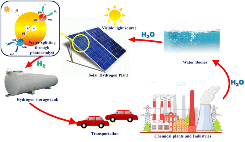 |
| | Fig. 1 Hydrogen generation and energy cycle driven by visible light. | |
After the famous Fujishima and Honda effect was discovered in 1972, that is hydrogen generation through the splitting of water over a single titania (TiO2) crystal under the influence of ultraviolet light,7 light-driven semiconductor photocatalyst-based technology has emerged as one of the most well-known methods for addressing the world's energy crisis.
The efficient storage of solar energy as an environmentally friendly, sustainable energy carrier is made possible through solar-to-chemical energy conversion; hydrogen is the most appealing and potential solar fuel produced via artificial photosynthesis. The production of hydrogen is made possible by solar water splitting, which combines solar energy with water.
2. Artificial photosynthesis
It is crucial to have a comprehensive understanding of the underlying chemical and physical processes to develop an effective photocatalyst. Some plants and microbes discover an effective pathway for converting solar energy into energy-rich materials and oxygen via photosynthesis with a maximum photochemical conversion efficiency of 6%. It reveals the level of difficulty in finding an “artificial photosynthetic” photocatalyst with an efficiency of more than 10%.
2.1. Photocatalytic water splitting
2.1.1. Single-step water splitting.
The simplest possible photocatalytic hydrogen generation process, demonstrated in Fig. 2(a), uses only a single semiconductor loaded with a cocatalyst as the active surface site. By absorbing photons from solar radiation, the electrons in the valence band (VB) get excited and move into the conduction band (CB). Prior to any catalytic activity, the excited CB electrons and VB holes (charge transporters) would move to the semiconductor material's surface sites. If the potential difference between CB and VB satisfies the conditions for water reduction and oxidation, the photocatalytic hydrogen generation will be feasible via a water-splitting reaction.8
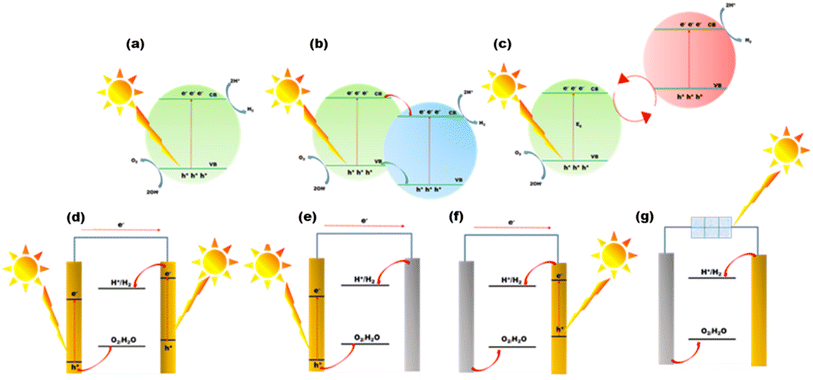 |
| | Fig. 2 (a) One-step water splitting, (b) heterojunction formation, (c) Z-scheme water splitting, (d) photoanode (left) and a photocathode (right), (e) photoanode (left) and a counter electrode (right), (f) counter electrode (left) and photocathode (right), and (g) photovoltaic-electrolysis system with a solar cell. | |
2.1.2. Heterojunction formation.
During heterojunction formation, charge separation is enhanced and charge recombination is minimized. As shown in Fig. 2(b), a heterojunction is formed between two distinct photocatalysts with adjacent band structures. The VBs of two semiconductors can contain different sets of active electrons.10 After charge activation, electrons from one photocatalyst with a reduced conduction band potential will move to another photocatalyst with a higher conduction band potential, which is the semiconductor that the electrons prefer thermodynamically. When the semiconductor has a lower valence band potential, the holes on the opposite side will flip to it. By stacking supporting semiconductors such as C3N4 sheets one on top of the other,9 heterojunctions can be constructed. As an alternative, the junctions can also be built by combining the same materials but at different phases.
Limitations.
Wideband gaps in these semiconducting materials necessitate powerful driving forces for efficient water redox reactions. Additionally, if the band gap is too large, solar light can only be used for photons with very high energy and short wavelengths.
2.1.3. Z-scheme two-step water splitting.
Setting up photocatalysts with narrower band gaps is necessary in order to maximize the use of the longer-wavelength solar radiation (visible spectrum), which makes up the vast majority of the solar irradiation spectrum. A Z-scheme photocatalyst is constructed, as illustrated in Fig. 2(c),9 without altering the hydrogen generation driving force of narrow bandgap photocatalysts. To transfer electrons amongst the two structures, a pair of reaction matrix ions from the same substance that have differing redox levels act as a reduction–oxidation shuttle. The shuttle ions will engage in surface reduction–oxidation processes in competition with the water molecules in addition to serving as an electron transmission chain amongst the two photocatalysts. The Z-scheme is divided into two parts: the first is associated with the oxidation and the second with the reduction of water. To accomplish total water splitting, multiple semiconductor photocatalysts that are not functional in a single semiconductor system are discovered to be functional in Z-schemes.11,12
Limitations.
To meet the necessary practical applications, there is a need for the STH to be around 10% or the AQY to be 60% at 600 nm.13,14 It is necessary to tailor the band structures of existing materials and construct new semiconductor materials. At the same time, special attention is paid to the surface design for enhancing the kinetics of overall water splitting and developing an effective charge separation path.
2.2. Photoelectrochemical (PEC) water splitting
Another effective system for splitting water with solar energy is the PEC cell. For better light absorption and exciton formation, semiconductor materials are placed as a thin film onto the electrode surface.9,15 The photoanode and photocathode cooperate in the arrangement, as shown in Fig. 2(d). The photogenerated holes oxidize water on the anode. H2O is converted into H2 by the electrons generated in the photocathode as they move across the ohmic contact to replace the holes in the VB on the photoanode. Designing a system with a highly active anode and cathode is difficult. Surface cocatalysts are also needed to speed up the kinetics of water redox reactions to increase the cell efficiency. Fig. 2(e) and (f) show a photolytic anode or cathode and a counter electrode made of a noble metal. These counter electrodes are often quite active for water redox processes. As a result, the rate of water splitting in these cells will be constrained by the effectiveness of H2O redox reactions on the photolytic cathode and anode sides, respectively.
2.2.1. Limitations.
Finding a semiconductor with suitable band gaps and effective solar radiation absorption is the first challenge. Second, the overpotential is often high because an efficient cocatalyst is needed as a layer on the semiconductor for kinetically challenging water oxidation events. Therefore, there is a critical need for efficient cocatalysts to boost a PEC cell's STH efficiency.16
2.3. Photovoltaic-electrolysis water splitting
The combination of water electrolysis cells and solar cells is being investigated in the light of the rapid advancement of solar cells. This type of system, as shown in Fig. 2(g), functions similarly to a water electrolyzer.17,18 The only distinction is that the solar cells producing electricity provide energy. The efficacy of the solar cell in the water electrolysis cell will determine the total effectiveness of STH in this system. They function substantially better than the complete photocatalytic hydrogen generation setups exhibited previously. They are particularly promising for the future due to their high efficiencies, which provide excellent STH performance.
2.3.1. Limitations.
This approach still does not yield enough hydrogen to be economically viable due to the high cost of manufacturing and operating reliable solar cells.19 Nevertheless, considering the probable rise in the cost of producing H2 from petroleum and other natural gases, and the decline in the price of solar panels, it can be predicted that the photovoltaic-electrolysis technique will be a viable option in the future to store solar energy in H2.
3. Photocatalytic hydrogen generation
Photocatalytic hydrogen generation is emerging as an effective method to directly use solar energy to produce hydrogen via a water-splitting process.7 When semiconductor photocatalysts absorb photons of 380–700 nm, electrons are excited from the valence band to the conduction band, resulting in free electrons and holes in the CB and VB, respectively. Fig. 3(a) shows the schematic of an oxygen evolution catalyst (OEC) and a hydrogen evolution catalyst (HEC). Three sequential stages comprise the photocatalytic water splitting mechanism that generates greener H2 and O2: (i) the absorption of light with energies above the band gap and excitation of electrons from the valence band to the conduction band; (ii) the dissociation of photoexcited radicals into free radicals and their subsequent movement to gather at the semiconductor's active sites; and (iii) the beginning of simultaneous reduction and oxidation reactions that utilize electron–hole pairs to generate H2 and O2 at the cocatalyst sites.20
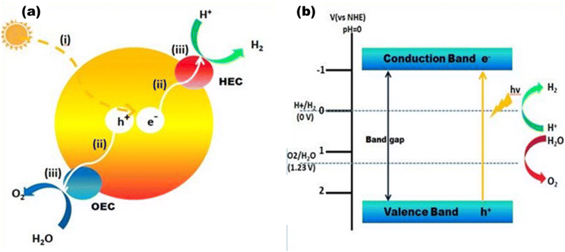 |
| | Fig. 3 (a) Overall water splitting: (i) light capture, (ii) charge separation and migration, and (iii) water redox reactions. (b) Energy diagram for overall water splitting. | |
Target reaction for photocatalytic hydrogen evolution:
Hydrogen evolution reaction (HER):
| 2H+ + 2e− → H2(g) ΔE0 = −0.41 V |
Oxygen evolution reaction (OER):
| 2H2O(l) → O2(g) + 4H+ + 4e− ΔE0 = +0.82 V |
Overall reaction:
The efficiency of the following three key processes together determines the overall solar energy conversion efficiency (ηtotal) which is expressed as follows:20–22
| ηtotal = ηabsorption × ηseparation × ηreaction |
where
ηabsorption is the fraction of incident light absorbed to produce electron–hole pairs;
ηseparation is the fraction of photoinduced charged radicals getting separated and migrated,
ηreaction is the efficiency of the surface processes involving the charge carriers at the solid–liquid interface.
Fig. 3(b) shows how the electrons in the CB reduce the protons to produce H2 at pH 10, and simultaneously, the holes in the VB oxidize to produce O2. The most important variables from the standpoint of a photocatalyst are the band gap size and the energies of the CB and VB. The redox potential of O2/H2O must be more positive than the valence band maximum (VBmax), and the redox potential of H+/H2 (0 V at NHE) must be more negative than the conduction band minimum (CBmin). Thus, 1.23 eV is the minimum theoretical band gap for water splitting, and ∼5 eV is the maximum band gap for photocatalysis, which is the cut-off wavelength of the solar spectrum.20 In order to initiate the HER and OER electron transfer processes at reasonable rates, it is expected that certain extra kinetic overpotentials are required, which exclude semiconductors with band gaps less than 1.6 eV.23 However, the utilization and maximization of light absorption from the entire solar spectrum range and lowering the charge recombination for the utilization of REDOX processes at the co-catalyst site are two major concerns in photocatalytic processes. Thus far, many semiconductor photocatalysts have been addressed with visible active properties, but the actual key to achieving solar-to-chemical energy conversion with >10% solar-to-fuel efficiency is combining them physically and electrically in an appropriate manner forming heterojunctions with wide bandgap semiconductors to make them useful in visible light active photocatalysis.24
3.1. Heterogeneous photocatalytic hydrogen production
A high-performance heterogeneous photocatalyst5 serves several factors, as shown in Fig. 4. Thus far, a wide range of semiconductor photocatalysts based hydrogen production have been studied, including solid solutions [(Ga1−xZnx)(N1−xOx) and (AgIn)xZn2(1−x)S2], chalcogenides (ZnS, CdS, and CdSe),25,26 metal oxides (TiO2, Cu2O, and ZrO2),27,28 and a wide range of carbonaceous materials (g-C3N4).20 Many approaches have been devised to design a stable and high-performance photocatalyst.5 The first tactic involves adding or removing atoms from the lattice structure in order to dope it with various elements. Common dopants such as Fe, C, B, and N lower the charge recombination and modify the energy gap.29,30 The second tactic involves connecting the photocatalyst to metals to generate semiconductor/metal heterojunctions, which can prevent rapid charge recombination and form a Schottky barrier. In order to lower the overpotential for surface electrochemical processes, the metal can also function as a cocatalyst. Additionally, the metal's surface plasmon resonance can enhance light absorption. Enhanced photocatalysis can be achieved by combining noble metals as co-catalysts rather than only semiconductors. Connecting two semiconductors is the third tactic, where one of the semiconductors can be used to oxidise the sacrificial agent such as water and reduce hydrogen, while the other can assist in (i) improving electron–hole pair separation and transport, (ii) sensitising the composite that catalyses the reaction to visible light, or (iii) acting as a co-catalyst such as CdS/TiO2 or TiO2/PbS.31,32 The Z-scheme is the common approach in which each semiconductor has one redox reaction. It permits the combination of two semiconductors: one with oxidation sites and the other with reduction sites. The Z-scheme photocatalyst features well-separated active sites and a significant redox potential as a result. To enable charge carrier transport between the semiconductors, certain Z-scheme catalysts include an electron conductor such as Au or Ag or a charge carrier mediator such as Fe2+/Fe3+ or IO3−/I−.33 Employing an organic or inorganic dye such as eosin Y onto the semiconductor surface is another cutting-edge method. These dyes have the ability to photosensitize to visible light. By means of their own photoexcitation upon exposure to visible light, they aid in the start of the photochemical process, which is then followed by the electron transfer to the semiconductor.34,35 Other tactic involves physically altering the three-dimensional structure of the semiconductor, maximizing its dimensions and enhancing its active surface area to augment the photocatalytic activity. For instance, various morphologies including spheres, rods, tubes, nanosheets, fibers, and linked architectures have been synthesized for TiO2.36 Quantum dots have recently been reported as promising materials with improved hydrogen production capabilities. Compared to typical nanoparticles, particles with sizes between 1 and 10 nm show superior charge transmission and separation characteristics.37 Consequently, there is growing interest in composite materials. g-C3N4-based materials, metal oxides, metal chalcogenides, COFs, MOFs, and other polymeric materials are the primary potential materials to enable the large-scale use of photocatalysis. The optimization of the system's operating conditions can also be considered for enhancing the performance of the photocatalyst. The pH of the solution is the most crucial factor. In order to choose the ideal pH levels, the Point of Zero Charge (PZC) of the surface of a semiconductor is another crucial parameter; at pH values greater than this, the surface deprotonates and becomes negatively charged, which draws cations. Furthermore, the photocatalyst surface becomes positively charged and draws anions when the pH value is lower than the PZC.5 Collectively, heterogeneous photocatalysts provide numerous excellent advantages over homogeneous photocatalysts. Starting from its ease of synthesis, the photocatalyst itself facilitates the water dissociation reaction without being consumed, and hence, the separation of the catalyst from aqueous phase is important. Heterogeneous photocatalysts (due to their different phases) are generally easier to filter out of the water splitting process, making them more suitable for use in prospective hydrogen generation systems in terms of both thermal stability and recyclability. Additionally, continuous flow operations can be scaled up for hydrogen generation using heterogeneous catalysts.38,39 In heterogeneous photocatalysis, the formation of a heterojunction is more feasible to meet the required criteria for a suitable, hence attainable quantum efficiency. By the formation of a multicomponent catalyst, the charge recombination rates can be reduced, charge transportation and migration can be enhanced, and photocorrosion and light harvesting properties can be taken care of. Moreover, in heterogeneous photocatalysis, the backward reactions during water splitting can be avoided by improving their crystallinity and facile properties. Crystallinity leads to a decrease in surface defects, resulting in lower recombination rates of photogenerated holes and electrons, and surface modification provides separate active sites for photoreduction and oxidation processes.40,41
 |
| | Fig. 4 Properties of heterogeneous photocatalysts. | |
3.2. Homogeneous photocatalytic hydrogen production
Homogenous photocatalysts too have some advantages over heterogeneous photocatalysts, which make them appropriate for effective water splitting. Because it is more beneficial to change the catalyst with different ligands to increase the catalyst's ability, homogeneous catalysts perform better than heterogeneous catalysts at lower temperatures.42,43 Therefore, homogeneous catalysts can also be utilized in hydrogen generation. Recyclability, however, is poor since it is challenging to recover the catalyst following the reaction. The first catalyst utilized in homogeneous photocatalytic hydrogen production was colloidal Pt, which employed TEOA as a sacrificial agent, [Ru(bpy)3]2+ as a chromophore, and [Rh(bpy)3]3+ as an electron mediator for generating H2 under solar light.44 To move the electrons from the photosensitive agent to the catalyst, an electron mediator was required. Soon after, a few investigations showed that it was possible to produce hydrogen by using a metal complex based on cobalt as a catalyst instead of Pt, which did not require any electron mediator.45 Since then, earth-abundant metals (Co, Ni, Fe, and Mo) or noble metals (Pt, Pd, and Rh) have been utilized in homogeneous catalytic systems. Noble metal nanoparticles are typically more stable than organometallic catalysts, but they are not applicable for large-scale hydrogen generation due to their limited availability and high expense.46 Homogeneous photocatalysts suffer from limitations such as system units' solubility in water, the process's low quantum yield, and the chemical stability over time. These systems, despite their ability to produce hydrogen on a large scale, have low quantum yields. This is explained by the poor electron transfer efficiency between the molecular catalyst and the excited photosensitizer.47 Another significant obstacle is enhancing the homogeneous catalyst's aqueous solubility, as water is typically the preferred proton source in real-world systems.48,49 Different approaches have been proposed to address these issues, as shown in Fig. 5. One of these involves strengthening the electron transfer processes by fastening all of the system's components together.50,51 Solvency issues are addressed by the application of surfactants such as polyvinylpyrrolidone (PVP) and sodium dodecyl sulphate (SDS). The dispersion of water-insoluble transition-metal complexes employed as proton reduction catalysts is aided by the formation of micelles in water by surfactants.52,53 Enhanced solubility of the catalyst in water may also be achieved by adding hydrophilic ligands into the catalyst coordination sphere. These tactics increase the catalyst's efficiency in producing hydrogen.5
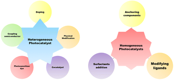 |
| | Fig. 5 Strategies for enhancing the photocatalytic behavior of homogeneous and heterogeneous photocatalysts. | |
3.3. Factors affecting photocatalytic water splitting
3.3.1. Band gap.
The electronic structure of a semiconductor catalyst can be illustrated in terms of band gaps that generally arise due to their difference in energy levels of valence band (VB) and conduction band (CB).54 Hydrogen production is thermodynamically feasible by the initial formation of H+ ion intermediates, where the photon-generated electrons reduce it to H2 over the binding sites of the catalyst. As reported earlier for the production of hydrogen, the optimum band gap need to be 1.23 eV.55 First, by raising light intensity with energies higher than the activation threshold, photocatalytic water splitting efficiency can be enhanced, and mainly visible light harvesting can be effectively increased by lowering the band gaps. Second, materials with low band gaps make charge migration and transportation easier, which gradually results in redox sites for water splitting. Therefore, modification and designing of semiconductor photocatalysts via engineering the band gaps is of higher importance,56Fig. 6 shows the bandgap of different semiconducting materials. Ismael et al.57 synthesized Ru-doped TiO2 with a lower band gap of 2.75 eV for enhanced H2 production of 3400 μmol h−1 under sunlight, which is two times (1500 μmol h−1) more than that of the pristine TiO2 with a band gap of 3.1 eV. Chachvalvutikul et al.58 successfully produced Bi2WO6/ZAg:ZnIn2Sn4In2S4 with a band gap of 2.42 eV and produced 1023.9 μmol h−1 g−1 of H2. Jiang et al.59 synthesized NiSe/Mn0.5Cd0.5S with a lower band gap of 2.33 eV with the highest H2 production rate of 27.98 mmol h−1 g−1. Gao et al.60 synthesized ZnIn2S4 with a larger band gap of 2.72 eV and Ag:ZnIn2S4 with an optimum bandgap of 2.64 eV, where H2 production rates were 617.58 μmol g−1 h−1 and 1591.03 μmol g−1 h−1, respectively, which showed that a lower band gap composite showed higher photocatalysis. Therefore, the lowering of band gap plays an important role for efficient photocatalysis.61
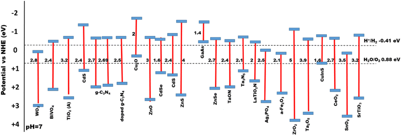 |
| | Fig. 6 Bandgap energies for a series of semiconductor-based photocatalysts. | |
3.3.2. pH.
Since proton decrease occurs when photoinduced electrons are produced during water splitting, it may be considered that the formation of H2 depends on the proton count, concentration, or pH of the solution.61 This particular component is particularly crucial for photoreformation, as it necessitates the existence of a sacrificial organic species. In weak basic pH solutions, H2 may be produced more efficiently than in acidic or strong basic (>10) pH solutions, and the band gap energy shift is influenced by pH changes.62 Using CuOx/TiO2, maximum water splitting was performed photocatalytically in a weak basic medium (pH 10), as shown in Fig. 7(a), according to Wu et al.63 However, as the Cu(I) species is less stable on the TiO2 surface in acidic media, at pH 2, the least amount of H2 was produced. According to Brahimi et al.,64 pH 11 was ideal for photocatalytic hydrogen production over CuAlO2/TiO2, as shown in Fig. 7(b). The catalyst band gap may also be reduced due to pH adjustments. Pt/r-TiO2 generated the most H2 at pH 5.5, or around 56.6 mmol g−1 h−1. Nonetheless, it is likely that the fundamental system's photocatalytic reaction offers more benefits to improve H2 evolution.
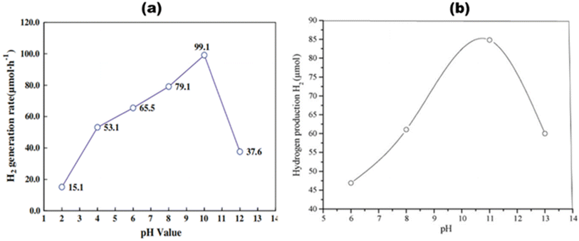 |
| | Fig. 7 Effect of pH on average H2 production rates of (a) CuOx/TiO2. Reproduced with permission. Copyright 2009 Springer63 and (b) CuAlO2/TiO2. Reproduced with permission. Copyright 2007 Elsevier.64 | |
3.3.3. Temperature.
Temperature cannot thermodynamically trigger photocatalysis since it does not contribute to the formation of electrons and holes. Temperature does, however, contribute to the enhancement of product desorption from the catalyst surface, which enhances the photocatalytic activity.61 The response rate increases with the temperature. For each catalyst, a different temperature is applied. As a result, the photocatalytic activity might be easily increased by adjusting this factor. A lower temperature has a negative effect by reducing the pace at which H2 is produced since the products' desorption slows down the reaction because the reactants' adsorption happens more slowly. Higher transfers of electrons in the valence band to greater energy levels are facilitated by high temperatures. As a result, it makes it easier for electrons to form, which may be employed to initiate oxidation or reduction processes, respectively, and makes the reaction more competitive with charge carrier recombination.65 Using methanol as the sacrificial agent, Velázquez et al.66 synthesized Pt–TiO2 and produced H2 with a controlled temperature range of 5–60 °C, where temperature seems to be an influential factor in the yield of H2. As shown in Fig. 8(a) at 60 °C, the yield of H2 was up to 38.0 mmol g−1 h−1 in the presence of methanol. Using methanol as the sacrificial agent, Fang et al.67 produced an inexpensive NiOx-loaded TiO2 catalyst, as shown in Fig. 8(b), for thermo-photo catalytic water splitting. Under simulated AM 1.5G sunlight at 260 °C, the catalyst with an ideal Ni ratio of 5 wt% achieved an apparent quantum efficiency of 66.24% and a H2 production rate of 53.7 mmol g−1 h−1, 2.5 times higher than that of the system operating in the darkness. More remarkably, the photogenerated H2 yields could still attain 26.9 mmol g−1 h−1 at this temperature when exposed to visible light (λ > 420 nm), which was five times more than that attained at normal temperature (0.0011 mmol g−1 h−1).
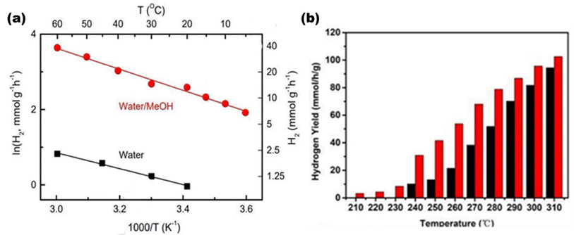 |
| | Fig. 8 (a) Hydrogen yield with respect to temperature and Arrhenius plots of 2Pt–TiO2 in the presence of water/methanol. Reproduced with permission. Copyright 2022 Elsevier.66 (b) Thermo-catalytic H2 yields (black bar) and thermo-photocatalytic H2 yields (red bar) over NiOx/TiO2 at different temperatures. Reproduced with permission. Copyright 2019 American Chemical Society.67 | |
3.3.4. Sacrificial agents.
When compared to water as a solvent, the performance of photocatalyst activity can be enhanced by the inclusion of organic species as sacrificial agents, which include a series of alcohols such as ethanol, methanol, phenol, isopropanol, ethylene glycol and glycerol, which serve as hole scavengers.61,68 It has become more vital to improve extremely effective photocatalysts for the generation of H2, although the impacts of sacrificial agents' composition and structure have been reported in limited studies. Alcohols are utilized in a process known as photo-reforming to increase the rate at which H2 is produced. This process develops semiconductors that facilitate the oxygenation of organic species and reduce H+ to H2, which is basically due to the mineralization of sacrificial agents. The general pathway of methanol as a scavenger is shown in the following equations:69
| CH3OH + OH˙ → CH2OH˙ + H2O |
Chen et al.70 produced a 1 wt% Cu/TiO2 photocatalyst depicted in Fig. 9(a), and investigated how the alcohol content (0–100 vol%) and type (methanol, ethanol, ethylene glycol, or glycerol) affected H2 generation rates, as shown in Fig. 9(b). H2 generation rates at a 10% alcohol concentration are as follows: glycerol > ethylene glycol > methanol > ethanol. The rates at 50 vol% are as follows: methanol > ethylene glycol > glycerol ≈ ethanol. For enhanced hydrogen production, Wang et al.71 synthesized CoS2@SCN, as shown in Fig. 9(c), and investigated the mechanism and charge transfer behaviors of several alcohol sacrificial agents on photocatalytic water splitting. The highest hydrogen activity of 223.6 μmol g−1 h−1, the lowest volume in-phase charge transfer resistance of 55.19 Ω, and the maximum photocurrent and photocurrent densities of 5.5 μA cm−2 and 0.63 mA cm−2 were all demonstrated by the nanocomposite CoS2@SCN when triethanolamine was used as the sacrificial agent.
 |
| | Fig. 9 (a) HR-TEM image of 1 wt% Cu/TiO2. (b) Average H2 production in the presence of different sacrificial agents for 1 wt% Cu/TiO2. Reproduced with permission. Copyright 2020 Elsevier.70 (c) Proposed structure and scheme for H2 production using the CoS2@SCN photocatalyst. Reproduced with permission. Copyright 2022 Elsevier.71 | |
3.3.5. Light harvesting.
The entire photocatalytic process is started by light absorption connected to semiconductors' electronic band structures, directly influencing the maximal solar light photocatalytic conversion efficiency. TiO2 generally performs quite well in photocatalytic hydrogen evolution; yet, due to its inherent band structure, it is only partially able to absorb UV light.61,72,73 According to the AM 1.5G solar spectrum depicted in Fig. 10(a),20 visible and infrared light with high photon energy make up 69.5% of the overall solar radiation range, whereas ultraviolet light only makes up 4.6%. Theoretically, photocatalytic one-step total water splitting requires a light acceptor with an absorption peak at 520 nm and a quantum efficiency of 100% [Fig. 10(b)] to achieve the desired STH of 10%. Therefore, it is important to make a material visible light active for effective photocatalysis. The occupied states of an intrinsic semiconductor's component parts define its energy band structure. In general, metallic element orbitals usually provide low energy to the CB, whereas non-metallic element orbitals primarily occupy the high-energy VB. Therefore, the light absorbance range and intensity are greatly influenced by the types, positions, and concentrations of faults.74,75 Even if there is a significant increase in light absorption, an overabundance of vacancies might lead to deeper energy band states as recombination centers, which would hinder photocatalytic activity.
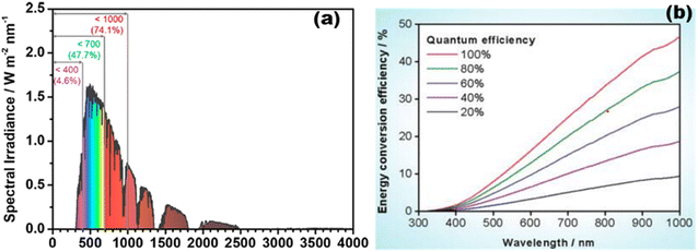 |
| | Fig. 10 (a) Computation source of solar irradiance is AM 1.5G data. Reproduced with permission. Copyright 2020 American Chemical Society.20 (b) Different quantum efficiencies to calculate the overall water splitting solar energy conversion efficiency as a function of wavelength. Reproduced with permission. Copyright 2010 American Chemical Society.269 | |
3.4. Determination of photocatalytic efficiency
3.4.1. Quantum yield.
The evolution rates of O2 and H2 as well as the photocurrent density are greatly affected by specific experimental procedures and water splitting conditions. Therefore, in order to compare the activity of photocatalysts under various reaction conditions, it is essential to ascertain the total quantum yield (QY), shown in eqn (1), or apparent quantum yields (AQY), shown in eqn (2) and (3), of a specific nanocomposite for solar radiation – assisted splitting of water.76 The measured QY is frequently the AQY because light dispersion makes it challenging to determine the precise number of photons absorbed by a semiconductor within a photocatalyst setup.71| |  | (1) |
STH and AQY are considered the efficiency terms for photocatalytic OWS in order to compare the results of various photocatalysts. Accurate evaluation is one of the most important factors in evaluating STH and AQY, even if it is not advised to apply the H2 evolution rate (r) as a benchmark to assess a photocatalyst's effectiveness. The impact of H2 on the incident solar energy is one of the crucial factors in the real-world use of photolytic visible light-induced catalytic splitting of H2O for green H2 generation. The AQY measures how many photoinduced charged carriers are utilized in the production of hydrogen or oxygen compared to photons that have an external incidence on the photocatalyst. It can be defined by eqn (2) and (3) and is also referred to as external quantum efficiency (EQE):77,78
| |  | (2) |
| |  | (3) |
or,
| |  | (4) |
In
eqn (4), the terms
n,
r, and
l represent the total no. of electrons (e
−) or holes (h
+) involved in photocatalysis, the rate at which gas is formed from the molecules involved in the reaction, and the flux of incident photons, respectively.
79
3.4.2. Solar-to-hydrogen conversion efficiency.
On the prospect of utilizing visible light to accelerate the breakdown of H2O into O2 and H2, studies on potential and ideal efficiencies, measurements of solar hydrogen production efficiencies, and technological analyses of various solar hydrogen possibilities have all been conducted. The analysis shows that the theoretical conversion efficiency limits for a single photosystem and a multiple photosystem approach for the 1-solar radiance are 31% and 42%, respectively. However, practical construction and material limitations will probably keep the conversion efficiency at or below 16%.80
By using a nanomaterial composite as the photocatalytic system, visible light-driven water breakdown can be accomplished in a reasonably simple manner just by solar light uptake followed by catalysis on a single device. When taking into account 5–10% solar-to-hydrogen conversion efficiency (STH) and five years longevity, the projected average cost for this photocatalytic setup is 1.6–3.5 USD per kg.17,81,82 This range satisfies the US Department of Energy's target of green hydrogen production with a cost of 2–4 USD per kg by 2020 to suit the replacement of fossil fuels. The STH is defined using eqn (5):
| |  | (5) |
where
S is the area that has been exposed to radiation,
Psun is the energy flux of the sunlight,
rH2 is the rate at which hydrogen gas is produced, and Δ
Gr is the reaction Gibbs energy. Solar radiation has an radiative flux of 1.0 × 10
−3 W m
2 and a distinct power spectrum when taking the ASTM-G173 AM1.5 global tilt into account.
83 The only source of energy input and output must be solar energy and H
2 must be evolved in a stoichiometric ratio with respect to H
2 and O
2 production.
79
3.4.3. Turn over number (TON) and turn over frequency (TOF).
The TON for hydrogen generation5 can be determined by the proportion of molecules that have reacted with an active site, as given in eqn (6):| |  | (6) |
Similarly, the TOF for the production of photogenerated H2 is determined by dividing the number of molecules reacting per second by the number of active sites, as given in eqn (7):
| |  | (7) |
3.4.4. Hydrogen evolution rate.
Temperature, pressure, and the reaction system are the environmental parameters that will affect the rate of H2 evolution. The performance must be assessed at 10–25 °C in a vacuum system in order to develop a testing standard for lab-based research. Through the use of a closed circulation system that uses water cooling, this is simply accomplished and maintained. To measure the gas evolution rates, the device is often used together with an online gas chromatograph. The evolved oxygen and hydrogen gases collected in the system, however, will alter the reaction environment and pressure of gases as the reaction advances, causing a shift in the rate of gas evolution.
When the hydrogen and oxygen evolution rates are low, the influence of pressure is tolerable. The capacity of the reaction solution to disintegrate when subjected to radiation under low pressures, which increases the partial pressure of gaseous water molecules in the setup, is another source of inaccuracy. It can be challenging to accurately estimate the composition of the product gas because of the non-uniform gas components that can be produced by the condensation and evaporation of water within a closed circulation network. It is recommended to check the system under conditions that are similar to those of the anticipated reaction in order to reduce mistakes. It seems improbable that a photocatalytic overall water splitting reactor could continue to function well at low pressures and temperatures. Therefore, it makes more logical to assess STH effectiveness at ambient pressure and temperature. A gas-purge-type flowing reaction device coupled with a gas chromatograph is a reliable technique for assessing the product gas. It is possible to maintain the same reaction conditions such as atmosphere and pressure throughout the reaction course using a flow reaction device. Since the oxygen and hydrogen produced are not collected in the system and a trace quantity below the detection sensitivity threshold cannot be precisely quantified, it is very difficult to identify the STH if the photocatalyst is not adequately active.79
4. Nanomaterial selection and criteria for photocatalysis
Oxidation and reduction reactions take place simultaneously in a photocatalytic reaction; hence, materials with both oxidizing and reducing tendencies are required. Semiconducting materials are the best suitable as they can undergo both oxidation and reduction and have a moderate band gap, but a lower recombination rate is required for their use as a photocatalyst. Moreover, 43% of the visible light is contained in the solar spectrum. For a good photocatalyst, the band gap must be between 1.23 and 3 eV for its functioning in the visible spectral range. For the determination of water redox processes, the band structure plays a crucial role. For effective reduction and oxidation, the conduction band position should be more negative than the water reduction potential and the valence band position should be more positive than the water oxidation potential, respectively.84,85
4.1. Metal-decorated nanoparticles
Metal nanoparticles are majorly known for their semiconducting properties that can be utilized in several photocatalytic applications. There are several classes of nanoparticles based on the metal-nonmetal bonding, shown in Fig. 11. Among them, metal oxides are an important class of photocatalysts; they fulfill all criteria for good photocatalytic activity. These classes of catalysts are well suited for photocatalysis due to their favorable band gap, carrier mobility, electronic structure, and light absorption. Synthesis of low-cost, stable metal oxides that can utilize total UV-visible light is yet a challenge. Metal oxides basically possess enhanced qualities such as structure modification, reusability, and large surface area. Some of the examples are oxides of zinc, chromium, and vanadium.86 Mainly transition metal ions (Mn+) having d0 (Ce4+, V5+, Ti4+, Ta5+, Zr4+, W6+, and Nb5+) or d10 (Ga3+, Zn2+, Ge4+, Sb5+, In3+, and Sn4+) configurations make up the majority of metal oxide photocatalysts that act as catalysts for hydrogen and oxygen production. Here the VBs constitute the 2p orbitals of O, while the CBs of metal oxides constitute the d and sp hybrid orbitals of metal ions.34,35
 |
| | Fig. 11 Schematic of the types of metal-based semiconductor photocatalysts, the challenges faced during photocatalytic water production and the strategies to improve the catalytic activity. | |
Moreover, some 4d transition metals including Ru, Rh, Pd, and Ag and 5d transition metals including Os, Ir, Pt, and Au are excellent co-catalysts for the photocatalytic water breakdown process. In particular, Au and Ag are the chief co-catalysts in the visible light-driven hydrogen generation because of their high surface plasmon resonance (SPR) effects through the oscillations of the conduction electrons. Alkali metals, certain lanthanide ions, and alkaline earth metals often only contribute to the formation of the crystal structure and not the band structure. The symmetries of the VB and CB as well as the metal oxygen octahedral (Ohd) and tetrahedral (Td) coordination are believed to be the primary factors influencing water splitting despite the fact that there are numerous diverse metal oxides with different crystal and electronic structures.87,88 Among the metal oxides, the most explored TiO2 nanoparticles are well known due to their range of properties such as greater photocorrosion stability, non-toxicity, low cost and good redox potential values.89 They are the most diffused catalyst, but their large bandgap of ∼3.2 eV makes them limited to only the UV region and not the visible region. Therefore, extensive research on the TiO2 system has come into light.90–92 Prior to certain challenges regarding metal oxides, additional types of metal-based photocatalysts include VBs composed of non-metallic elements such as Se, S and N. Other nanoparticles include metal hydroxide, chloride, phosphate, sulphides, and fluoride nanoparticles, which can be classified based on their morphological, size, chemical, and physical properties. However, several challenges such as broad bandgap, higher recombination rates and photocorrosion effect of several metal-based nanomaterials limited their applications in photocatalysis, which can be overcome by using advanced strategies such as surface modification with dyes that act like visible light photosensitizers [Fig. 12(a)]; deposition of plasmonic metals such as Au, Cu, Ag, and Pt onto the surface of the catalyst [Fig. 12(b)]; doping of n-type and p-type semiconductors with the catalyst to modify the bandgap [Fig. 12(c)]; quantum dot modification on the surface of active photocatalysts [Fig. 12(d)]; metallic ion doping by a controlled amount of doping materials in the crystal lattice that can narrow the bandgap as seen in various resulting colored materials; nonmetallic doping with elements such as N, C, or S that shows a redshift in the absorption edge of the catalyst or the formation of heterostructures with catalysts for narrowing the bandgaps93 [Fig. 12(e)].
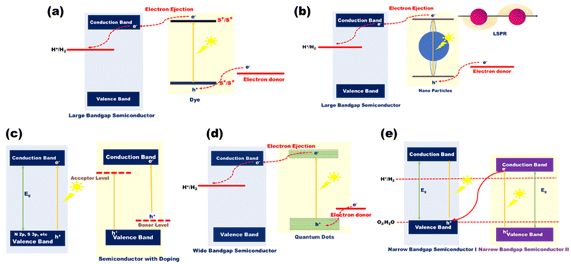 |
| | Fig. 12 Schematic mechanism of (a) dye-sensitized, (b) LSPR-induced, (c) valence band-engineered, (d) quantum dot-enhanced, and (e) Z-scheme-type photocatalytic approaches. | |
In the light of composites of metals other than oxides, de Respinis M. et al.94 as depicted in Fig. 13(a) showed that in meta nitrides and (oxy)nitrides, less electronegative nitrogen constitutes more negative VBs than oxygen, while there is hardly any change observed in the CB potential by the addition of any nonmetal like nitrogen. For instance, by substituting the O2− ions in Ta2O5 with N3− ions, the VBMax in TaON and Ta3N5 is raised to more negative potentials. Since metal chalcogenides with one or more electropositive elements often have VBs made up of oxygen group elements (S2, Se2, or Te2), they provide much swallower p-orbitals than oxygen and claim to be a good choice for solar light-driven photocatalysis. CdS, as an illustration, demonstrates favorable charge transfer characteristics and an appropriate band gap with the potentials of the pertinent redox processes. AgInS2 was synthesized by Gu et al.95 using a low-temperature liquid technique, and Mn2+ was doped for H2O splitting. AgInS2 and Mn-doped AgInS2 (1![[thin space (1/6-em)]](https://www.rsc.org/images/entities/char_2009.gif) :
:![[thin space (1/6-em)]](https://www.rsc.org/images/entities/char_2009.gif) 100) had hydrogen evolution rates of 53 μmol h−1 g−1 and 73 μmol h−1 g−1, respectively, with band alignments of 1.63 and 1.52 eV, respectively. By adding multi-walled carbon nanotubes, the hydrogen production was increased even more, reaching 105 μmol h−1 g−1.
100) had hydrogen evolution rates of 53 μmol h−1 g−1 and 73 μmol h−1 g−1, respectively, with band alignments of 1.63 and 1.52 eV, respectively. By adding multi-walled carbon nanotubes, the hydrogen production was increased even more, reaching 105 μmol h−1 g−1.
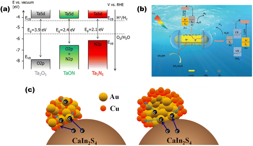 |
| | Fig. 13 Schematic of (a) band diagrams for Ta2O5, TaON, and Ta3N5 demonstrating the changes in the VBM after nitridation. Reproduced with permission. Copyright 2015 American Chemical Society.94 TSPR and LSPR electron injection in (b) Pt-modified Au–TiO2. Reproduced with permission. Copyright 2020 Royal Society of Chemistry96 and (c) Au, Cu/CaIn2S4. Reproduced with permission. Copyright 2018 Elsevier.97 | |
Based on the plasmonic effect, Zhu et al.96 synthesized a Pt-modified Au–TiO2 nano-dumbbell that produced 80 μmol g−1 h−1 of hydrogen due to injection [as shown in Fig. 13(b)] of energetic hot electrons from excitation and decay of LSPR and transverse SPR in Au-nanorods. Ding et al. synthesized a97 plasmonic Au, Cu/CaIn2S4 hybrid composite, where the bimetallic nanoparticles are deposited on monoclinic bimetallic sulfide [as shown in Fig. 13(c)] that produced 452.8 μmol h−1 of hydrogen due to synergetic and SPR effects of Au and cu nanoparticles.
Based on photosensitized photocatalysts, Han et al.98 synthesized an Eosin Y (EY)-sensitized SrTiO3 photocatalyst, as demonstrated in Fig. 14(a), where 491.5 μmol of hydrogen was produced in 2.5 h. Tan et al.99 synthesized a 2D/3D hybrid structure [as shown in Fig. 14(b)] of ZnIn2S4-photosensitized TiO2 nanosheets that produced 1167.38 μmol−1 g−1 h−1 of hydrogen.
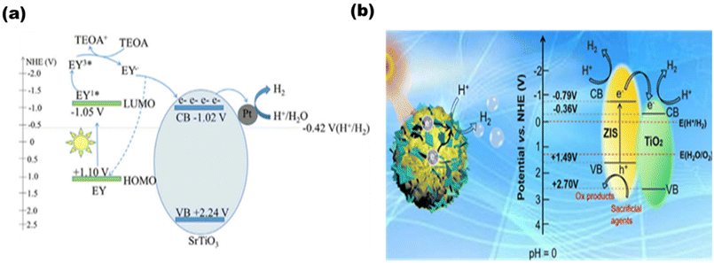 |
| | Fig. 14 Schematic of (a) EY-sensitized SrTiO3 for hydrogen production. Reproduced with permission. Copyright 2020 Elsevier98 and (b). ZnIn2S4–TiO2. Reproduced with permission. Copyright 2022 Elsevier.99 | |
Based on the type of doping, Liu et al.100 synthesized M-doped Mo2C (M = Fe, Co, Ni, and Cu), as shown in Fig. 15(a), where the work function (Wf) was engineered by varying the dopant 3d metal series for the modulation of Fermi levels of the catalyst. The highest yield of hydrogen was reported with Cu doping, i.e. 521 μmol−1 h−1, which is largely due to lower resistance of Cu at the solid–solution interface and the highest interface capacitance among all the transition metals [Fig. 15(b)]. Moreover, lower Wf favors enhanced hydrogen production, which is due to more adsorption of water to the catalyst. The long-term photo-stability of the catalyst was confirmed by the cycle study [Fig. 15(c)].
 |
| | Fig. 15 Photocatalytic performances based on (a) H2 yield rates of TiO2-M-Mo2C, (b) H2 yield rates with mean errors, and (c) stability cycles of the catalyst. Reproduced with permission. Copyright 2021 Elsevier.100 | |
Based on metal hybrid photocatalysts, Naik B. et al.101 synthesized core–shell structured SiO2@Ag NCs@Ag3PO4, as depicted in Fig. 16(a) for overall water splitting, where the LSPR-induced mechanism due to Ag plasmonic NCs resulted in effective charge separation, enhancing the overall photocatalytic activity and stability of the photocatalysts with a hydrogen yield rate of 37.4 μmol in 4 h. Park Y. J. et al.102 depicted another set of core–shell structured Pt/SiO2@m-oxides (m-oxides = titania, niobium oxide, tantalum oxide, and cesium oxide), as depicted in Fig. 16(b)via a surface tailoring route, where the greater surface exposure of the metal NPs and the large interfacial surface area for the potent SMSI action enhance the photocatalytic activity. Naik B. et al.103 also extended another core–shell nanostructured copper-silver bimetal alloy as a co-catalyst in a SiO2@TiO2 photocatalyst. By applying a fine thin layer of titania to spherical silica nanoparticles measuring 100 nm in size, a core–shell hybrid nanocomposite was produced. The copper-silver alloy was then deposited using a straightforward reduction procedure. The surface plasmon resonance from a copper–silver alloy supplies hot electrons to the CB of titania via the Schottky junction, resulting in eight times greater photocurrent and three times higher H2 production activity.
 |
| | Fig. 16 (a) Detailed schematic illustrating the synthesis of SiO2@Ag@Ag3PO4, with the production of SiO2 nanoparticles as the first step and amine functionalization as the second. The second phase involves depositing Ag NCs via a chemical reduction route and Ag3PO4via an ion-exchange route, both of which are then heated to 500 °C. Reproduced with permission. Copyright 2019 American Chemical Society.101 (b) Diagrammatic representation of the production process for Pt/SiO2 hybrid nanocatalysts enclosed in different metal oxides. Reproduced with permission. Copyright 2013 Elsevier.102 | |
4.2. Metal–organic linker-decorated frameworks
Metal–organic frameworks (MOFs) have mostly been explored owing to their adjustable and tunable properties, and unusual structural and chemical stabilities. Chemically MOFs are represented as hierarchical porous crystalline solids with metal ions (di, tri or tetravalent mono or bi-) as the centers with their nodes bonded to organic linkers (bi-functional polycarboxylates, nitrogenated hetero-cyclic compounds or organophosphorus compounds) as their constructive units.104 Similar to the electronic structures in other classes of photocatalysts, MOFs too have positive band positions known as HOMOs (highest occupied molecular orbitals) and negative band positions known as LUMO (lowest unoccupied molecular orbitals) that undergo REDOX reactions. However, MOFs with several advantages such as flexibility and versatility still fail to solve certain challenges [as shown in Fig. 17] for efficient photocatalysis, and hence, several strategies such as ligand functionalization, mixing of ligands or metal centers, hybrid structures, dye sensitization, metal nanoparticles loading or coupling of MOFs with COFs or other semiconductors105 can be utilized to make them suitable candidates for visible light-active photocatalysts.106
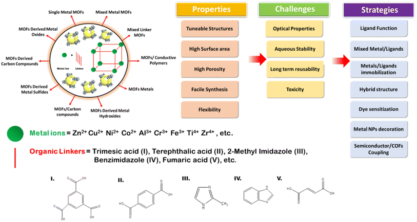 |
| | Fig. 17 Scheme showing MOF formation, types, validity, common challenges and strategies to improve the photocatalytic activities of MOFs. | |
Based on MOF systems and their above-discussed strategies for improving photocatalysis, He et al.107 for the first time described anchoring the of a CdS nanostructure over MIL-101 and noted a significant impact on water splitting (as reported ∼150 μmol h−1 of H2) when exposed to visible light. A Au@CdS/MIL-101 ternary photocatalyst was prepared by Wang et al.,108 where the careful fabrication of CdS was done upon Au nanoparticles grown over the surface of MIL-101, as shown in Fig. 18(a), and this hybrid composite with the ordered crystal facet [Fig. 18(b)–(d)] was reported to yield 250 μmol h−1/10 mg of H2, which was almost 2.6 times more than that by pure CdS. Jin Z. and Yang H.109 synthesized another system with Pd-loaded Zr-MOF catalysts by impregnation reduction. Reported data show an excellent hydrogen yield of 9.1 mmol g−1 under visible light illumination and EY as a photosensitizer.
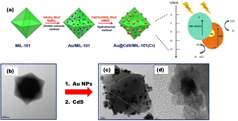 |
| | Fig. 18 (a) Au@CdS/MIL-101(Cr) synthesis route. TEM images of (b) MIL-101 and (c) Au@CdS/MIL-101. (d) HR-TEM image of Au@CdS/MIL-101. Reproduced with permission. Copyright 2016 Elsevier.108 | |
An anthracene-constituted bipyridine ligand was also successfully discussed by Chen et al.110 to form a multilayer Cu(I)-MOF with a smaller band gap of 2.13 eV, which showed high photocatalytic hydrogen evolution in water (75.89 mmol g−1 in 18 h) and had remarkable chemical stability, maintaining the integrity of its framework across the varied pH range of 2–13. The CdS@Cd(II)-MOF@TiO2 ternary nanocomposite was synthesized, as shown in Fig. 19(a), by Zhao et al.,111 where the hybrid nanocomposite displayed an extraordinary H2 evolution rate of 1604 μmol h−1 g−1 and a quantum yield of 2.31%, which is largely due to the synergetic effects of tri-components [Fig. 19(b)].
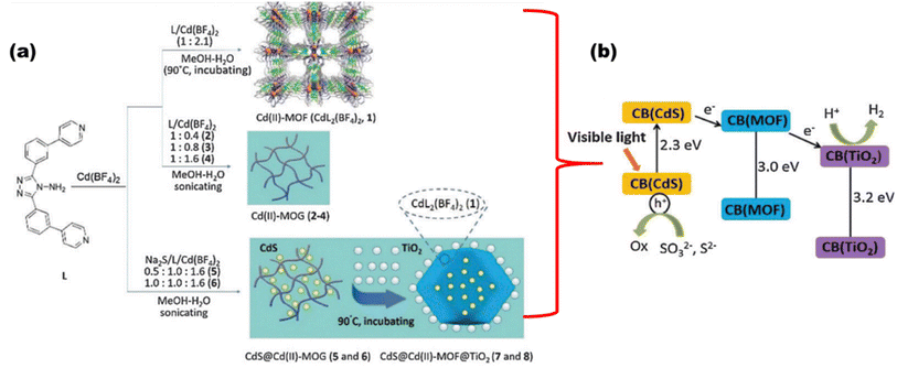 |
| | Fig. 19 (a) Synthesis route. (b) Schematic showing charge transfer and water reduction in CdS@Cd(II)-MOF@TiO2. Reproduced with permission. Copyright 2015 Royal Society of Chemistry.111 | |
In the light of photocatalysis, extensive research and findings for the chemistry of MOFs are ongoing focusing on MOF catalysts. Recently, Mao et al. have synthesized hierarchical structured UiOS-Cu-CdS/ZnS112 [as shown in Fig. 20], wherein CdS/ZNS QDs were loaded upon Cu2+ decorated on a thiol-functionalized MOF base. Here, MOF acts as the medium for charge transfer between the metal sulfides, and the loading of Cu2+ shifts the HOMO of MOF to a higher position than the VB of CdS forming a type-II heterojunction. The reports show a hydrogen yield of 425.5 μmol h−1 with 10 mg catalyst loading and an AQE of 24.6%.
 |
| | Fig. 20 Schematic of the synthesis of UiOS-Cu-CdS/ZnS. Reproduced with permission. Copyright 2021 Elsevier.112 | |
Jin et al.113 constructed a heterojunction photocatalyst with Mn0.2Cd0.8S nanorod loading on the surface of flakey Ni-MOF-74 [as the surface topography shown in Fig. 21(a) to (d)], which provided an excellent channel for electron–hole transfer that reported 7.104 mmol g−1 h−1 [Fig. 21(e) to (g)].
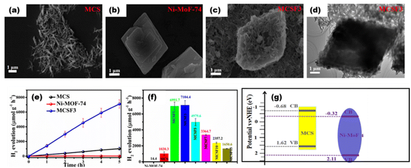 |
| | Fig. 21 SEM images of (a) Mn0.2Cd0.8S, (b) Ni-MOF-74, and (c) composite. (d) TEM image of the composite. (e) H2 yield with respect to time. (f) H2 yield with respect to composition. (g) Schematic of heterojunction formation. Reproduced with permission. Copyright 2022 American Chemical Society.113 | |
4.3. Metal-free polymeric covalent-bonded organic frameworks
COFs are highly crystalline and nanoscale porous organic polymers formed by covalent linkage with regular structural building units. COFs are mainly linked by imines, boronic esters, boroxines, azines, hydrazones or ketoenamine bonds and their dimensions can be varied depending on the dimensions of the building components.114 Several properties, as shown in Fig. 22, make them suitable for stable and metal-free photocatalysts. However, their synthetic routes, reaction conditions and cost make them a complex approach. Moreover, their photocatalytic properties such as light harvesting, charge recombination and photostability factors are yet an area of concern. Therefore, some of the strategies such as structure engineering, linkage pre-design, bandgap engineering, crystallinity optimization, metal species utilization, COF hybrids and heterojunction formation can be done to enhance the utilization of COFs in photocatalysis.115
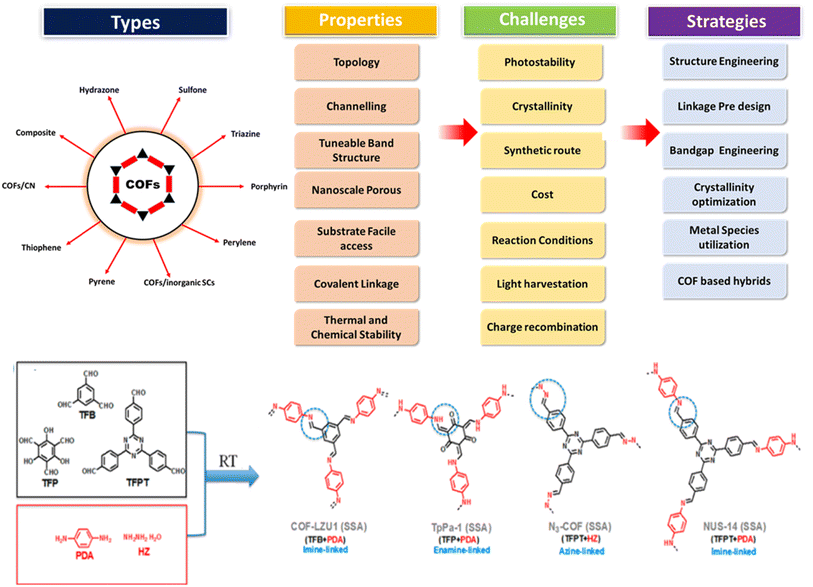 |
| | Fig. 22 Scheme showing COF formation, types, validity, common challenges and strategies to improve the photocatalytic activities of COFs. Reproduced with permission. Copyright 2020 Elsevier. Reproduced with permission. Copyright 2023 Royal Society of Chemistry.114,115 | |
Based on hybrid COFs, Chen et al. synthesized a hydrazone-linked hetero-COF shell on the core structure of octahedral NH2-UiO-66 with a higher surface area and multi-pores that enhanced charge separation and transfer [Fig. 23(a)], ultimately resulting in a H2 yield of 7178 mmol g−1 h−1.116Fig. 23(b) shows the core–shell formation of the MOF with COF and their faceted cube structure. Zhou et al.117 reported a mixed ligand (tertiary phenyl and benzothiazole) synthesized COF with a 1,3,5-triformylphloroglucinol node. COFs with 5 mol% benzothiazole ligand (acting as the light absorber and electron acceptor moiety) produced the highest amount of H2 up to 9839 μmol g−1 h−1. Yang et al.118 synthesized three imine-based crystalline COFs with various acceptor–donor moieties. COFs with a triazine acceptor and a triphenylamine donor form the strongest moieties with the highest H2 evolution rate of 20.7 mmol g−1 h−1.
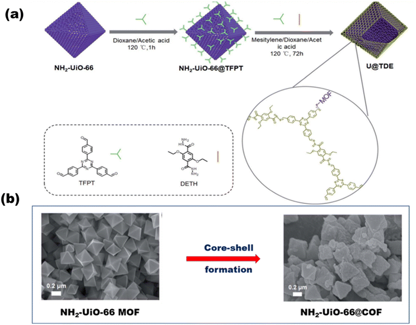 |
| | Fig. 23 (a) Schematic of the synthesis of NH2-UiO-66@COF. (b) SEM images of the core MOF before and after core–shell formation. Reproduced with permission. Copyright 2020 Royal Society of Chemistry.116 | |
Xu et al.119 synthesized a 2D/2D heterojunction between a triphenylphosphine-based semiconducting COF and a triazine ring COF. Due to the favorable band alignment (2.6 eV for the P-COF and 2.3 eV for the triazine COF) of both the materials, a type II heterojunction (2.5 eV) was formed for charge transfer, and the reported hydrogen yield was around 14![[thin space (1/6-em)]](https://www.rsc.org/images/entities/char_2009.gif) 100 μmol h−1 g−1, which is 2.5 times higher than that of the pristine COFs. Liu et al. synthesized a Schiff-base-formed 2D fluorine-COF120 [as shown in Fig. 24(a)] with 2,3,5,6-tetrafluoroterephthaldehyde and 2,4,6-tris(4-aminophenyl)-1,3,5-triazine. The presented COF provides a high surface area and a reduced band gap [as shown in schematic Fig. 24(b), and UVDRS data Fig. 24(c)], resulting in charge separation and an enhanced photocatalytic hydrogen production efficiency of 80 μmol g−1 h−1 [as shown in Fig. 24(d) and (e)]. Ma et al.121 synthesized 2D COF-JLU100 with a sp2 hybridized triazine carbon ring and attained higher crystallinity, surface area, good charge carrier mobility and durability. The reported value of hydrogen yield was 100
100 μmol h−1 g−1, which is 2.5 times higher than that of the pristine COFs. Liu et al. synthesized a Schiff-base-formed 2D fluorine-COF120 [as shown in Fig. 24(a)] with 2,3,5,6-tetrafluoroterephthaldehyde and 2,4,6-tris(4-aminophenyl)-1,3,5-triazine. The presented COF provides a high surface area and a reduced band gap [as shown in schematic Fig. 24(b), and UVDRS data Fig. 24(c)], resulting in charge separation and an enhanced photocatalytic hydrogen production efficiency of 80 μmol g−1 h−1 [as shown in Fig. 24(d) and (e)]. Ma et al.121 synthesized 2D COF-JLU100 with a sp2 hybridized triazine carbon ring and attained higher crystallinity, surface area, good charge carrier mobility and durability. The reported value of hydrogen yield was 100![[thin space (1/6-em)]](https://www.rsc.org/images/entities/char_2009.gif) 000 μmol g−1 h−1, which is the highest H2 production seen under visible light illumination (>420 nm). This excellent yield may be due to extended cyano-vinylene π-delocalization, which fastens charge separation and transportation, resulting in ideal photocatalysis. Recently, Dong et al.122 constructed a well-matched band structured heterojunction COF, where a hybrid organic/inorganic COF (TpPa-1-COF/ZnIn2S4-20%) was synthesized, which showed S-scheme photocatalytic mechanism with a H2 yield of 853 μmol g−1 h−1 and an AQE of 2.08%.
000 μmol g−1 h−1, which is the highest H2 production seen under visible light illumination (>420 nm). This excellent yield may be due to extended cyano-vinylene π-delocalization, which fastens charge separation and transportation, resulting in ideal photocatalysis. Recently, Dong et al.122 constructed a well-matched band structured heterojunction COF, where a hybrid organic/inorganic COF (TpPa-1-COF/ZnIn2S4-20%) was synthesized, which showed S-scheme photocatalytic mechanism with a H2 yield of 853 μmol g−1 h−1 and an AQE of 2.08%.
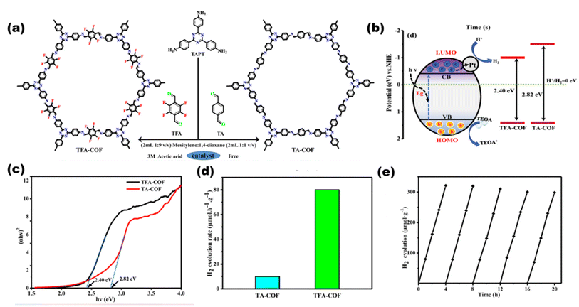 |
| | Fig. 24 Schematic of the (a) synthesis of COFs and (b) photocatalysis pathway. (c) Bandgap plots for the COFs. (d) H2 production rates of TA-COF and TAF-COF. (e) Catalytic life time. Reproduced with permission. Copyright 2021 Elsevier.120 | |
4.4. Carbon–nitrogen-decorated polymeric graphitic carbon nitrides
Belonging to the class of metal-free polymeric semiconducting materials, graphitic carbon nitride with its metal-free structures, higher surface area, good photoelectric properties, and easy availability has gained tremendous interest in photocatalytic applications. Wang et al.123 have previously reported in 2009 that solar light can be utilized in photocatalytic water dissociation processes using graphitic carbon nitride structures. The advantages of g-C3N4 over inorganic semiconductors are easy synthesis, a greener environment, and adaptable band structures. Moreover, it favors higher water splitting due to its optimal optical absorbance (about 460 nm) and suitable CB position (around 1.4 V). With a simple bottom-up supramolecular self-assembly process, Liu T. et al.124 produced 3D g-C3N4 composed of extremely thin, highly crystalline nanosheets, as shown in Fig. 25(a). Three-dimensional g-C3N4 NS has a significant amount of specific surface area due to the unique 3D porous interconnected open framework, which serves as a supporter to prevent nanosheet agglomeration [as shown in Pl-intensity data Fig. 25(b)] and as a route for electron transport with tuned bandgaps [a shown in UVDRS plot Fig. 25(c)]. It showed the highest AQY in g-C3N4 sheets of 1.4% at 420 nm, in accordance to which the H2 yield was lowest in g-C3N4 bulk [Fig. 25(d)] and highest in g-C3N4 nanosheets [Fig. 25(e)]. Wang et al.125 reported photocatalytic hydrogen production utilizing g-C3N4 doped with Pt, PtOx, and CoOx. g-C3N4 with a band structure of 2.8 eV at 422 nm responds well to the solar spectrum. With 0.3% AQY, it exhibited reaction stability for 30![[thin space (1/6-em)]](https://www.rsc.org/images/entities/char_2009.gif) 600 minutes. From a combination with an N-rich precursor and NH4Cl as fuel, Hu C. et al.126 produced phosphorous dopped C3N5 nanosheets through heat treatment and protonation method. The produced C3N5 nanosheets showed exceptional photocatalytic H2-evolution capability with an increased surface area (20-fold greater than that of bulk C3N5). By polycondensing dicyandiamide and an ionic liquid that contains phosphorus as a source of heteroatom, Zhang et al.127 synthesized g-C3N4 with phosphorus doped into it, which exhibited improved photocatalytic capabilities.
600 minutes. From a combination with an N-rich precursor and NH4Cl as fuel, Hu C. et al.126 produced phosphorous dopped C3N5 nanosheets through heat treatment and protonation method. The produced C3N5 nanosheets showed exceptional photocatalytic H2-evolution capability with an increased surface area (20-fold greater than that of bulk C3N5). By polycondensing dicyandiamide and an ionic liquid that contains phosphorus as a source of heteroatom, Zhang et al.127 synthesized g-C3N4 with phosphorus doped into it, which exhibited improved photocatalytic capabilities.
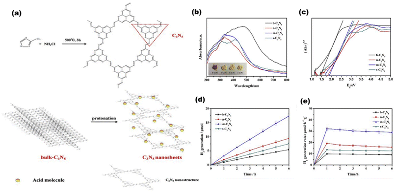 |
| | Fig. 25 (a) Schematic showing the formation of g-C3N5 in bulk and then in nanosheets. (b) PL-spectra. (c) UVDRS. (d) Hydrogen evolution rates of g-C3N5 bulk. (e) Hydrogen evolution rates of g-C3N5 sheets. Reproduced with permission. Copyright 2020 Elsevier.124 | |
Chang et al.128 synthesized a K+ and cyano group-decorated g-C3N4 [as shown in Fig. 26(a)] by one pot synthesis method, where K+ ions induced increased electron density in heptazine bonds and cyano is an electron withdrawing group that delocalized the valence electrons in the conjugated rings of the heterostructure, resulting in tuned bandgaps for various composites [Fig. 26(b) and (c)] with an increased hydrogen production rate of 1319 μmol h−1 g−1 [Fig. 26(d) and (e)]. Cheng et al.129 synthesized an ultrathin porous g-C3N4 (labeled as BCN-HT100) by a hydrothermal process from biuret that formed biuret hydrate, which upon thermal polymerization produced the final material.
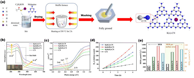 |
| | Fig. 26 (a) Synthesis of the K(x)-g-C3N4 scheme. (b) UVDRS spectra. (c) Plots of the converted Kubelka–Munk function vs. photon energy. (d) H2 yield per surface area. (e) H2 yield over CN and K(x)-CN. Reproduced with permission. Copyright 2023 Elsevier.128 | |
The as-synthesized ultrathin nanosheet possesses high polymerization degree with larger surface area and pores, resulting in an efficient hydrogen yield of 21![[thin space (1/6-em)]](https://www.rsc.org/images/entities/char_2009.gif) 252 μmol h−1 g−1 and an AQE of 58.7%, and such excellent photocatalytic behavior is seen due to increased charge separation and transportation as well as provided with a larger number of reactant sites. Another ultrathin g-C3N4 nanosheets were synthesized by Zhang et al.267 by recrystallizing urea from DMF to form a H-bonding network, which resulted in ultrathin nanosheets by further calcination at 550 °C. This facile method approach provided an enhanced hydrogen production rate of 2.5 × 10⁻⁴ mol h−1, which is largely due to the increased surface morphology of the g-C3N4 structure.
252 μmol h−1 g−1 and an AQE of 58.7%, and such excellent photocatalytic behavior is seen due to increased charge separation and transportation as well as provided with a larger number of reactant sites. Another ultrathin g-C3N4 nanosheets were synthesized by Zhang et al.267 by recrystallizing urea from DMF to form a H-bonding network, which resulted in ultrathin nanosheets by further calcination at 550 °C. This facile method approach provided an enhanced hydrogen production rate of 2.5 × 10⁻⁴ mol h−1, which is largely due to the increased surface morphology of the g-C3N4 structure.
Apart from the synthesis of cutting-edge nanomaterials for advanced photocatalytic hydrogen production, extensive research is ongoing to scale up the process, as shown in Table 1. By virtue of visible light-mediated solar cells, a large number of countries are shifting to “green” hydrogen fuel for their future energy needs. This area of scalability has mostly been explored by Domen et al.130 where they reported water splitting upon Ta3N5 grown on the edges of KTaO3 on 100 m2 arrays of panel reactors. T. Takata et al. studied the overall water splitting of SrTiO3:Al loaded with Rh, Cr, and Co as cocatalysts131,132 that resulted in an internal quantum efficiency close to unity. Reisner et al.133 reported a bio-abiotic hybrid system where Sporomusa ovata was grown on rhodium co-doped strontium titanate (SrTiO3:La,Rh) and molybdenum-doped bismuth vanadate (BiVO4:Mo). They have also134 reported cellulose, hemicellulose, and lignin over cadmium sulphide quantum dots. By modulating the atomic ratio of Cu for solar photocatalysis, Liu Q.-Y. et al.135 have demonstrated triangular nanostars of Au–Cu alloys upon CdS for photocatalytic H2 production upto 607 μmol g−1 h−1 under light illumination. The construction of solar photocatalytic panels is in the infantry stage, and only the mentioned couple of groups have a few reports on large-scale hydrogen production. In 2021, the Department of Science and Technology (DST), under Chauhan D. K. et al.138 at the Institute of Nano Science and Technology (INST), Mohali, India will have designed a reactor that efficiently and sustainably produces large amounts of H2 from renewable resources such as water and sunlight. The INST team employed carbon nitride, an inexpensive and abundant organic semiconductor that can be easily produced on a kilogram scale using cheap precursors such as urea and melamine. The photocatalyst was coated on panels that allowed water to flow through the reactor (around 1 m2). Successful application of photocatalysts (suspended powders) in large-scale prototype reactors for hydrogen production is now being worked on. The National Green Hydrogen Mission has also been constructed and emphasized to speed up efforts to produce carbon-free fuel from renewable sources. Chauhan et al.137 employed hydrothermal synthesis of CuCo2S4 nanosheets for hydrogen generation. In India, Preethi L. K. et al. have also136 extensively studied the doping of hetero-junction TiO2 as the effective photocatalyst in recent times for H2 generation. Melvin et al.39 reported an M-Au/TiO2 (M = Ag, Pd, and Pt) hybrid nanocomposite for photocatalytic hydrogen generation without any sacrificial agent. Patra and Gopinath140 reported bimetallic and plasmonic Ag–Au on TiO2 as photocatalysts for overall water splitting. Our team139 early in 2015 reported the photogenerated greener H2 production by platinum-deposited N-TiO2. Earlier, Narayan Pradhan et al.141 shed light on harvesting hydrogen from metal semiconductor heterostructures photocatalytically.
Table 1 Various photocatalysts with hydrogen evolution rates and their photocatalytic activities
| Photocatalyst |
Surface loading |
Fabrication method |
Reaction condition |
Efficiency |
Ref. |
| SiO2@TiO2 |
Cu–Ag |
Facile reduction Stober method |
≥420 nm STSC-1:3 |
H2 = 1560 μmol h−1 g−1 |
142
|
| QE = 2.91 |
| SiO2@Ag NCs@Ag3PO4 |
Ag |
Stober's chemical reduction ion-exchange |
2 wt% Ag NCs, ≥420 nm |
AQE = 4.6% |
101
|
| H2 = 2460 μmol h−1 g−1 |
| O2 = 1236 μmol h−1 g−1 |
| CoS-2 (∼2.6 eV) |
|
Solvothermal |
pH 7.0, ≥420 nm |
H2 = 1196 μmol h−1 g−1 |
143
|
| ZnO (3.7 eV) |
Au |
Thermal decomposition |
10% wt Au, >400 nm |
H2 = 709 μmol h−1 g−1 |
144
|
| O2 = 559 μmol h−1 g−1 |
| Bi3TiNbO9 (∼3.3 eV) |
|
Molten-salt & solid state |
pH value of 9–10, >400 nm |
H2 = 342.6 μmol h−1 g−1 |
145
|
| O2 = 275.2 μmol h−1 g−1 |
| Porphyrin (1.77 eV) |
|
|
300–700 nm |
Solar spectrum efficiency of 44.4% |
146
|
| H2 = 40.8 μmol h−1 g−1 |
| O2 = 36.1 μmol h−1 g−1 |
| N–TiO2 (2.3 eV) |
|
Facile and environmentally friendly |
≥400 nm |
H2 = 602.7 μmol3 h−1 |
147
|
| TiO2 |
Ag–Au |
Photodeposition |
400–650 nm |
AQE = 3.3% |
140
|
| H2 = 718 μmol h−1 g−1 |
| TiO2 |
Pt–Au |
Photodeposition |
>400 nm |
H2 = 1.3 ± 0.07 μmol h−1 g−1 |
39
|
| AQE = 6.4% |
| Na2ZrTi5O13 (Nanobelt) (3.60 eV) |
CuO |
Solvocombustion |
600 °C, 400 nm |
STH = 2.83 |
148
|
| H2 = 2909 μmol h−1 g−1 |
| S,N–TiO2 (∼3.2 eV) |
Au |
Coprecipitation & deposition precipitation |
Au (3.5 nm) deposited on ∼12 nm size of anatase TiO2 600 nm |
Energy conversion efficiency = 17.6% |
149
|
| H2 = 267.6 μmol h−1 g−1 |
| O2 = 17.6 μmol h−1 g−1 |
| p-MoS2/n-CeO2 (2.97 eV, 1.89 eV) |
|
Hydrothermal method |
2 wt% MoS2, >430 nm |
H2 = 721 μA cm−1 |
150
|
| Co/P |
|
Solvothermal method |
At 353 K, 430 nm |
131.6 μmol h−1 at 353 K |
151
|
| AQE = 42.55% |
| ZnO–TiO2 (∼3.2 eV) |
|
TiO2 by anodizing titanium foil, ZnO by chemical bath deposition |
420 nm |
H2 = 44 μL cm−2 240 min−1 |
152
|
| N-TiO2 |
MgO |
Sol gel method, photodeposition method, hydrothermal method |
<470 nm |
H2 = 11![[thin space (1/6-em)]](https://www.rsc.org/images/entities/char_2009.gif) 000 μmol h−1 g−1 000 μmol h−1 g−1 |
153
|
| Q.E. = 81.8% (437 nm)–3.2% (1000 nm) |
| CoO (∼1.6 eV) |
|
Femtosecond laser ablation & mechanical milling |
>460 nm, air tight flask, pH (6.7–6.9) |
STH ∼5% |
154
|
| H2 = 11 ml |
| O2 = 5.5 ml |
| GaFeO3 (∼2.7 eV) |
|
Sol gel |
>395 nm, 600–900 °C |
QE ∼0.13% |
155
|
| H2 = 0.1 μmol h−1 |
| O2 = 0.04 μmol h−1 |
| BiOBr (∼3.05 eV) |
|
Microwave assisted solvothermal |
≥400 nm, pH 160 °C |
H2 = 1316.9 μmol h−1 g−1 |
156
|
| Bi2Ga4O9 (2.9 eV) |
RuOx |
Sol gel, band structure engineering |
≥430 nm, 180 °C |
AQE = 0.09% |
157
|
| H2 = 41.5 μmol h−1 g−1 |
| O2 = 19.6 μmol h−1 g−1 |
| SrTiO3:Rh, Sb |
Rh, Sb, IrO2 loading |
Solid state reaction |
>440 nm |
AQE = 0.1% |
158
|
| H2 ∼4 μmol h−1 |
| O2 ∼2 μmol h−1 |
| SrTiO3:Al (3.2 eV) |
Rh, Cr and Co |
Photodeposition or impregnation |
360 nm, Rh (0.1 wt%), Cr (0.05 wt%), Co (0.05 wt%) |
EQE = 96% |
77
|
| BiVO4-SrTiO3 |
Rh, Ru |
Impregnation, liquid–solid state reaction |
420 nm, neutral pH, at 2.5 wt% |
QE = 1.6% |
159
|
| H2 = 47.2 μmol h−1 |
| O2 = 22.4 μmol h−1 |
| CdS |
Pt, RuDTC |
High-temperature hot injection method |
>460 ± 50 nm, acidic condition (pH 6.0) |
AQE = 0.10% (Pt) & 0.27% (RuDTC) |
160
|
| H2 = 170 μmol h−1 |
| O2 = 71 μmol h−1 |
| Mn(bpy)V4O11 (bpy) (1.6 eV) |
Pt |
Hydrothermal |
420 < λ < 800 nm |
H2 = 92 μmol h−1 g−1 |
161
|
| O2 = 21 μmol h−1 g−1 |
| Ta3N5 (nanorods) (2.1 eV) |
Rh–Cr2O3 |
Solid state reaction |
<590 nm |
STH = 0.014% AQY = 2.2% (320 nm), 0.22% (420 nm) and 0.024% (500 nm) |
130
|
| H2 ∼10 μmol h−1 |
| O2 ∼5 μmol h−1 |
| LaMg1/3Ta2/3O2N (2.1 eV) |
TiOXH, RhCrOX |
Thermal ammonolysis |
<590 nm |
AQY: 0.18% at 440 ± 30 nm |
162
|
| H2 ∼22 μmol h−1 |
| O2 ∼11 μmolh−1 |
| Sn3O4 (2.4 eV) |
Pt |
Hydrothermal method |
>400 nm |
H2 = 40 μmol h−1 g−1 |
163
|
| CDs/CoO (2.51 and 2.42 eV) |
|
Electrochemical method |
>400 nm, 5 wt% CDs |
H2 = 1.67 μmol h−1 g−1 |
164
|
| O2 = 0.91 μmol h−1 g−1 |
| RuP/Al2O3/Pt(in)/HCa2Nb3O10 (nanosheet) |
|
Electrostatic attraction, solid state reaction |
420 nm |
H2 = 189.9 μmol |
165
|
| O2 = 82.6 μmol |
| TON = 1260 Hz |
| TOF = 440 h−1 |
| AQE = 2.4% |
| CDots-C3N4 (2.8 eV) |
|
Electrochemical method followed by hydrothermal treatment with ammonia |
550 °C for 3 hour <440 nm |
AQY = 16 (420 ± 20 nm), 6.29 (580 ± 15 nm)and 4.42% (600 ± 10 nm), STH = 2% |
166
|
| g-C3N4 (2.8 eV) |
Pt–Co |
Chemical reduction rational synthesis |
<440 nm |
AQY: 0.3% at 405 nm |
125
|
| H2 = 1.2 μmol h−1 |
| O2 = 0.6 μmol h−1 |
| g-C3N4 (nanosheet) (3.0 eV) |
Co1-phosphide |
Facile phosphidation method |
<410 nm |
QE = 3.6% (420 nm), 2.2% (500 nm) and 0.35% (580 nm) |
167
|
| H2 = 126.8 μmol h−1 g−1 |
| O2 = 64.5 μmol h−1 g−1 |
| g-C3N4 (4.048 eV) |
B, S |
Chemical reduction |
≥420 nm |
H2 = 53.2 μmol h−1 g−1 |
168
|
| O2 = 64.5 μmol h−1 g−1 |
| mp-g-C3N4 (3.0 eV) |
Pt |
Sol–gel/thermal condensation, photoreduction |
3 wt% Pt, <420 nm |
STH = 0.12% |
169
|
| H2 = 0.22 L kW h−1 |
| ∼18L H2 in one month |
| g-C3N4 (2.67 eV) |
Zn |
Soft-chemical |
≥420 nm, 10%-Zn/g-C3N4 |
H2 = 59.9 μmol h−1 |
170
|
| QE: 3.2% |
| g-C3N4/TiO2 (3.3–3.5 eV) |
|
Template method |
g-C3N4:TiO2 = 2.5![[thin space (1/6-em)]](https://www.rsc.org/images/entities/char_2009.gif) : :![[thin space (1/6-em)]](https://www.rsc.org/images/entities/char_2009.gif) 1, ≥420 nm 1, ≥420 nm |
H2 = 200.806 μmol h−1 g−1 |
171
|
| g-C3N4 (2.7 eV) |
S |
Facile heating |
>420 nm |
QE: 2.6% |
172
|
| H2 = 12.16 μmol h−1 |
| mp-g-C3N4 (2.57 eV) |
Ni |
Chemical reduction |
400 nm, 2 wt% Ni@SGCN |
H2 = 4.6 μmol h−1 g−1 |
138
|
| AQE = 1.1% |
| g-C3N4/WS2 |
|
Gas–solid reaction method |
|
H2 = 101 μmol h−1 g−1 |
173
|
| ZnIn2S4/g-C3N4 (∼2.6 eV) (∼2.8 eV) |
|
Thermal, polymerization, hydrothermal deposition |
15 wt%, ZnIn2S4, >400 nm |
H2 = 14.1 μmol h−1 |
174
|
| g-C3N4/InVO4 (3.1 eV) |
|
Hydrothermal process |
20% InVO4, >420 nm |
AQE = 4.9% |
175
|
| H2 = 212 μmol h−1 g−1 |
| ZnO/ZnS/g-C3N4 (∼3.6 eV) |
|
Solid state thermal decomposition, chemical precipitation |
|
H2 = 1205 μmol g−1at 4 h |
176
|
| MIL-125-NH2 (∼3 eV) |
Ni2P |
Solvothermal method |
450 nm |
H2 = 894 μmol h−1 g−1 |
177
|
| AQE = 6.6% |
| PtSA-MNSs |
Pt |
Solvothermal method |
>420 nm |
H2 = 11![[thin space (1/6-em)]](https://www.rsc.org/images/entities/char_2009.gif) 320 μmol g−1 h−1 320 μmol g−1 h−1 |
178
|
| g-C3N4/α-Fe2O3 (∼2.68 eV) |
|
Solvothermal method |
>420 nm |
H2 = 2066.2 μmol g−1 h−1 |
179
|
| MOF-253-Pt |
Pt |
Solvothermal method |
440 nm |
H2 = 28![[thin space (1/6-em)]](https://www.rsc.org/images/entities/char_2009.gif) 000 μmol g−1 (28 h) 000 μmol g−1 (28 h) |
180
|
| AQE = 1.63% |
| Ti3-BPDC-Ir |
Ru |
Solvothermal method |
NA |
H2 = 6632 μmol g−1 (72 h) |
181
|
| NU-1000-Ni |
|
Solvothermal method |
NA |
H2 = 14![[thin space (1/6-em)]](https://www.rsc.org/images/entities/char_2009.gif) 400 μmol g−1 (1 h) 400 μmol g−1 (1 h) |
182
|
| UiO-66/CdS/RGO |
Pt |
Solvothermal method, photodeposition method |
NA |
H2 = 13![[thin space (1/6-em)]](https://www.rsc.org/images/entities/char_2009.gif) 800 μmol g−1 (1 h) 800 μmol g−1 (1 h) |
183
|
| UiO-66(COOH)2/ZnIn2S4 |
MoS2 |
|
NA |
H2 = 13![[thin space (1/6-em)]](https://www.rsc.org/images/entities/char_2009.gif) 800 μmol g−1 (1 h) 800 μmol g−1 (1 h) |
183
|
| ZIF-67/Zn0.5Cd0.5S |
|
Hydrothermal method calcination method |
>420 nm |
H2 = 23![[thin space (1/6-em)]](https://www.rsc.org/images/entities/char_2009.gif) 265 μmol g−1 (1 h) 265 μmol g−1 (1 h) |
184
|
| Co3O4/CoO/Co2P |
Co2P |
Solvothermal method |
>420 nm |
H2 = 6.00 mmol g−1 (1 h) |
185
|
| CdS/Co9S8 |
|
Solvothermal method |
420 nm |
H2 = 61![[thin space (1/6-em)]](https://www.rsc.org/images/entities/char_2009.gif) 900 μmol g−1 (8 h) 900 μmol g−1 (8 h) |
186
|
| Co3O4/TiO2 |
|
Hydro(solvo)thermal method |
AQE = 2.4% |
H2 = 51![[thin space (1/6-em)]](https://www.rsc.org/images/entities/char_2009.gif) 200 μmol g−1 (6 h) 200 μmol g−1 (6 h) |
187
|
| CdS/MIL-125-NH2, (2.66 eV) |
|
Solvothermal method |
|
H2 = 19![[thin space (1/6-em)]](https://www.rsc.org/images/entities/char_2009.gif) 860 μmol g−1 (3 h) 860 μmol g−1 (3 h) |
188
|
5. Challenges
Photocatalytic systems can be a viable option because they use solar energy to power the photocatalytic hydrogen generation at the active site of the composite. When compared to other artificial systems, this setup makes use of low-cost photocatalysts and simple reactor construction.1 However, before further examination of their practical and social availability, a number of difficulties must be overcome. The utmost challenge lies raising the photocatalytic activity for water breakdown and hydrogen generation. Almost half a century later, till date the greatest effective photocatalytic material also exhibited an STH of 1%, which is considerably below the minimum suggested aim of 10%. The next challenge is that it is difficult to achieve long-term stability of the photocatalysts, which is still a question to be solved. The design of a method for removing and condensing H2 and O2 from the reactor system is another challenge. Additionally, the substantial setup required to switch from lab-scale to large-scale water splitting remains difficult.2 Research on the practical and social viability of photocatalytic hydrogen production is useless without addressing these difficulties. Any semiconductor that satisfies the aforementioned criteria can be employed for photocatalytic hydrogen evolution. However, some semiconductors have a photo-corrosion characteristic that renders them unsuitable for photocatalysis. The main reasons for low efficiency rates are as follows:
Recombination: most of the time, there is a greater probability of photoinduced electron and hole recombination, which is followed by enormous production of photons (as heat energy) and undesired heat.
Reversible reaction occurrence: when water splits into hydrogen and oxygen, the energy increases. The rate of the reverse reaction or recombination is improved by this increase in energy.
Visible radiation absorption: the forbidden band structure of titania lies between UV and solar spectrum regions; part of UV, i.e., only 4%, is utilized, whereas 50% of visible light remains unused. As a result, the efficiency of photocatalysts is diminished due to this limiting factor.189
6. Strategies
6.1. Lowering charge carrier migration distance
A smaller charge carrier migration distance should always be attained by reducing the photocatalyst. Ideal electron–hole gathering is possible if the size of the suspended nanoparticles is smaller than the electron–hole diffusion length. The synthesis procedure, circumstances, initial materials, and resulting particle size all have a significant impact.190 Earlier Kato et al. synthesized La-doped NaTaO3 that provided increased photocatalytic efficiency due to the reduced size of the particle, as shown in Fig. 27(a). Here, NiO–NaTaO3:La showed an AQY of 56% at 270 nm,191 and the increase in crystallinity by La doping was confirmed by SEM images, as shown in Fig. 27(b).
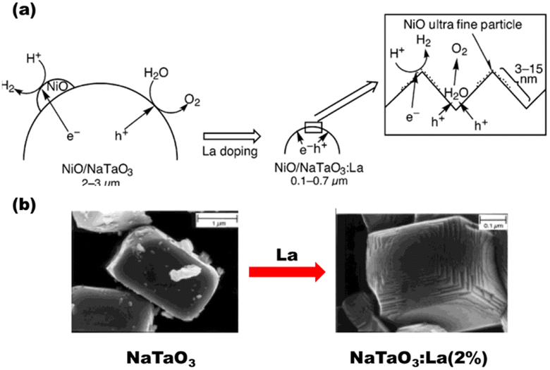 |
| | Fig. 27 (a) Pathway for HERs and OERs over NiO/NaTaO3:La semiconductor photocatalyst. (b) SEM images of NaTaO3 and NaTaO3:La (2%). Reproduced with permission. Copyright 2003 American Chemical Society.191 | |
Another useful method for achieving the requirements for reducing the charge migration distance is nanostructural engineering. The purpose of surface engineering is to improve reactant surface adsorption, reaction, and product desorption by forming certain crystalline facets. Both the amount and the quality of the semiconductor crystal surfaces have an impact on surface engineering.15 The construction of photocatalytic nanomaterials with better properties requires careful structural design and preparation, where charges are regulated to keep them apart and use them to perform beneficial photocatalytic activity. Utilizing titania as an example, which has been studied primarily for its structural characteristics, controlled nanostructures in titania lead to enhanced photocatalysis. Titania nanostructures primarily consist of 1-D, 2-D, and 0-D nanowires, nanotubes, nanorods, and nanoparticles. These can be assembled into higher order structures such as mesocrystals and 3-D hierarchical structures and each of the nanostructures shows a different photocatalytic behavior.15 Some appealing options for photocatalytic designs include core–shell configurations. By adjusting the VB and CB of the core and shell nanomaterials to produce type I or type II junctions, they enable exciton manipulation. By doing this, it will be easier to separate the electrons and holes and employ them at the photocatalyst surface for chemical processes.192 As an illustration with silica hollow spheres as hard templates, monodisperse Ta3N5 hollow spheres (40 nm) were obtained, as depicted in Fig. 28(a). Recombination chances of the carrier charge transporter were significantly decreased by spatially combining different co-catalysts with the photocatalyst. Platinum was employed as a negative charge acceptor co-catalyst and deposited as the hydrogen evolution co-catalyst (HEC) onto the inner shell structure, and IrO2 (or CoOx) was employed as the source of electron and deposited as the oxygen evolution co-catalyst (OEC) onto the outer shell structure of Ta3N5;270 surprisingly, hollow spheres showed maximum hydrogen production rates compared to the core–shell composite [Fig. 28(b)]. Taking SiO2@TiO2 as a host in a chemical reduction reaction our team produced a core/shell-structured Cu and Ag deposited material (SiO2@TiO2@Ag/Cu), whose surface was enhanced by the cocatalyst loading. The SiO2 core remained inactive under visible light, while the surface layer onto which the cocatalysts were loaded absorbed light through transition from electron donor levels created by Ag–Cu to the CB of the TiO2.142
 |
| | Fig. 28 (a) Ta3N5 core/shell photocatalyst deposited with Pt and IrO2. (b) Periodic evolution of H2 on hollow spheres, core/shell particles, and a bulk Ta3N5 photocatalyst. Reproduced with permission. Copyright 2013 Wiley.270 | |
Photoexcited carriers were able to migrate more effectively [as shown in Fig. 29] to the surface active sites because the photoactive Ag–Cu ions were densely distributed over the surface of the core–shell structure. Consequently, the core/shell-type SiO2@TiO2@Ag–Cu demonstrated better photocatalytic activity during hydrogen production from an aqueous solution containing 10 vol% TEOA as a sacrificial donor under visible light as compared to samples containing more homogeneous cocatalysts.
 |
| | Fig. 29 Schematic and possible pathway for enhanced photocatalysis in the hybrid SiO2@TiO2@Ag–Cu core–shell structure. Reproduced with permission. Copyright 2020 American Chemical Society.142 | |
Wang et al.193 synthesized a class of hybrid hollow heterostructured Co9S8@ZnIn2S4, where metal sulfide nanosheets were grown upon dodecahedral Co9S8 cages; such combination produced 6250 μmol h−1 g−1 H2, which was far higher than the amount of H2 produced by ZnIn2S4, and such yield is due to the higher charge recombination rates in ZnIn2S4 than the hybrid nanostructure, which provided higher charge migration rates. Wang et al. further developed another hierarchical Co/NGC@ZnIn2S4 cage [as shown in Fig. 30(a)] for effective photocatalytic hydrogen generation by employing a novel approach to synthesize ultrathin ZnIn2S4 nanosheets on Co/NGC nanocages, which are composed of Co nanoparticles encased in few-layered N-doped graphitic carbon (NGC). ZnIn2S4 nanosheets produced H2 at a rate of approximately five times lower than that of the hollow composites with a substantially hybridized shell and ultrathin layered substructures (11![[thin space (1/6-em)]](https://www.rsc.org/images/entities/char_2009.gif) 270 μmol h−1 g−1), which were in accordance with the spectral data [as shown in Fig. 30(b) to (e)] of steady-state PL, TRPL, EIS and transient photocurrent supporting that Co/NGC@ZIS has enhanced charge carrier transition and reduced recombination.194 ZnIn2S4 has an appropriate bandgap of 2.44 eV that favors photocatalysis. As reported earlier, it lacks effective charge transportation and tends to recombine, so Wang et al.195 further attempted to improve the efficiency by loading NiCo2S4, which served as an electron storage medium for charge migration, and hence, NiCo2S4/ZnIn2S4 (5 mg NiCo2S4) hollow hybrid spheres were formed that allowed a three times better H2 yield of 78 μmol h−1 than ZnIn2S4.
270 μmol h−1 g−1), which were in accordance with the spectral data [as shown in Fig. 30(b) to (e)] of steady-state PL, TRPL, EIS and transient photocurrent supporting that Co/NGC@ZIS has enhanced charge carrier transition and reduced recombination.194 ZnIn2S4 has an appropriate bandgap of 2.44 eV that favors photocatalysis. As reported earlier, it lacks effective charge transportation and tends to recombine, so Wang et al.195 further attempted to improve the efficiency by loading NiCo2S4, which served as an electron storage medium for charge migration, and hence, NiCo2S4/ZnIn2S4 (5 mg NiCo2S4) hollow hybrid spheres were formed that allowed a three times better H2 yield of 78 μmol h−1 than ZnIn2S4.
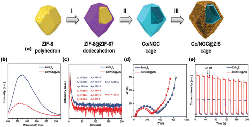 |
| | Fig. 30 (a) Diagram illustrating the formation of hierarchical Co/NGC@ZIS cages. (b) Steady-state photoluminescence data. (c) Time-resolved photoluminescence data. (d) Electrochemical impedance spectroscopy data. (e) Transient photocurrent spectra. Reproduced with permission. Copyright 2019 Wiley.194 | |
Another class of nanostructures consisting of layered graphitic carbon nitride and sandwich-like layered molybdenum disulfide MoS2/g-CN nanojunctions has previously been reported by Hou et al.196 Reducing the barriers to electron flow via the co-catalyst and expanding the accessible region surrounding the planar interface of the MoS2 and g-CN layers expedites the electron tunnelling effect that favours electron flow across the interface to produce the highest H2 of 20.6 mmol h−1 at 0.5 wt% composite.
6.2. Lowering defects
Defects that serve as thin trapping regions or active spots can enhance the photocatalytic activity and charge separation rate. The basic objective of photocatalysts is to reduce defects, both at the surface and the bulk.197,198 This is because numerous defects act as recombination spots for photoinduced charge transporters, reducing the photocatalytic behavior of the nanocomposite.199–202 The synthesis method has a significant impact on both the defect concentration and type. As an example, the structural defects were studied in g-C3N4. The photovoltage of the material appeared to monotonically drop as the synthesis temperature increased. These photocatalysts have a lower quasi-Fermi energy state and fewer photoexcited charge carriers. Near the CBMax and VBMax of g-C3N4 were two different kinds of flaws, as shown in Fig. 31. These flaws served as sites for electron and hole recombination.203 A molten salt flux approach can be used to change the synthesis of polymeric C3N4 and result in a more homogeneous end product. It has been shown that adding a salt solution (NaCl or KCl) can alter the final crystallinity of the material and its grain boundary structure while also preventing the spread of defects.204,205 A large number of photocatalytic materials with high levels of crystallinity and fewer defects have been obtained using this molten salt synthesis, including SrTiO3, PbTiO3,50,51 La–NaTaO3,146,206 Sn2TiO4,207 Ta3N5,208 La2Ti2O7,209 BaNb1-xTaxO2N,210 and Na2Ca2Nb4O13.211 This is made possible by the capacity of molten salts to speed up constituent ion diffusion and regulate crystal development during the synthesis. Ionothermally synthesized heptazine ring C3N4 crystals with reduced flaws can also be achieved, leading to a decreased photogenerated e−/h+ recombination rate.212,213 The catalytic activity seems to be increased by the optimised post synthesis calcination method in an NH3 or H2S environment, which further decreased the defect densities in (oxy)nitrides and sulphides, respectively.214,215
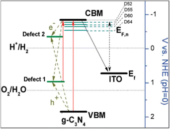 |
| | Fig. 31 Energy level diagram for graphitic carbon nitride displaying the ITO (+0.76 V), defect-2 (−0.38 V), and defect-1 (at +0.97 V) levels. Reproduced with permission. Copyright 2014 Royal Society of Chemistry.203 | |
6.3. Formation of the junction
A long carrier lifespan is crucial for the photosynthetic devices that govern the multielectron processes linked to fuel production, which usually require charge carrier separation across an interface. Takanabe et al. demonstrated a two-dimensional nanocomposite, where they explained the limitation of the potential gradient for charge separation that is visible in a narrow region over a composite surface.216 It is necessary to establish a low-loss electronic contact (tunnel junction or ohmic contact) in order to claim the capture of a large number of charge transporters within the nanocomposite. Because charge transporters must be efficiently directed by potential gradients, junctions formed between the semiconductors and metals with varying band structures, and the semiconductor and electrolyte have a significant impact on the features of PEC and photocatalytic devices. The inherent potential, charge concentration, and charge movement affect the junction formation.217 Surface modification of the photocatalyst with metal nanoparticles, analogous to loading a cocatalyst, is a fairly straightforward method of retrieving the charge carriers. A hot-carrier diode or an ohmic contact is produced at the metal–semiconductor interface, depending on the corresponding positions of the workfunction (of the metal) and Fermi energy (Ef) of the composite. In order to make an ohmic contact with a semiconductor (p-type), an integer greater than Fermi energy is typically required. Therefore, metals such as Au (=5.1 eV), Pt (=5.7 eV), and Rh (=5.0 eV) are frequently used as HECs. A metallic conductor whose value is less than Ef can therefore be used to produce an ohmic contact [as shown in Fig. 32] when working with n-type materials. Effective photoanodes have been developed via this technique, in which metallic materials act as contact layers that draw electrons away from the semiconductor components. Titanium-deposited BiVO4,218 tantalum-deposited SrTiO3,219 tantalum-deposited LaTiO2N,220 and tantalum-deposited BaTaO2N221 are a few types of these systems. Making composites with other semiconducting materials is another frequently used method for withdrawing photoinduced negative charges from the semiconductor material to reduce carrier charge recombination. A semiconductor interface between the layers of similar semiconductors is a type of159,222,223 phase junction, like those found in TiO2, which enables carrier charge transporter separation. The formation of a phase junction between the surface anatase and the underlying rutile nanoparticles improves the photocatalytic efficiency of TiO2.224–226
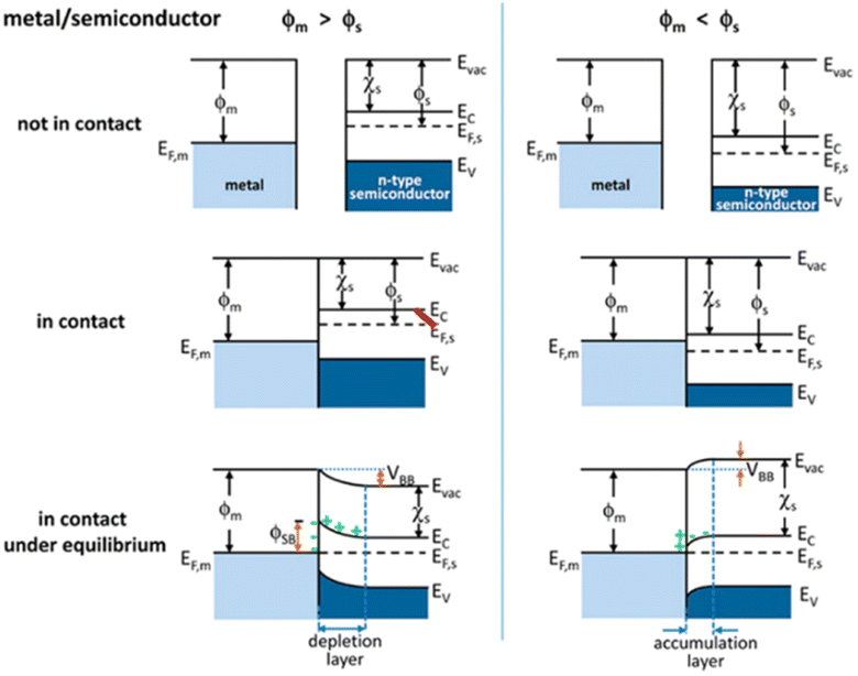 |
| | Fig. 32 Band structure of metal and n-type semiconductor contact. Reproduced with permission. Copyright 2012 American Chemical Society.227 | |
The heterojunction can be constructed under the categories of p–n junction, n–n junction, or p–p junction [as shown in Fig. 32 and 33], depending on the semiconductors used. In earlier research, Lee et al.222 obtained a light-sensitive nanodiode made up of CaFe2O4 (p-type) and PbBi2Nb1.9W0.1O9 (n-type). CaFe2O4 nanoislands were dispersed across a highly crystalline layered perovskite-based lattice consisting of PbBi2Nb1.9W0.1O9 to produce a nanodimensional p–n junction.223 Recently Huang et al.228 constructed a hierarchical Co3O4@CdIn2S4 p–n heterojunction photocatalyst that showed a CO generation rate of 5300 μmol h−1 g−1. Most n- and p-type semiconductors developed electron–hole pairs using this photocatalytic nanodiode. Looking into the types of heterojunctions, in type I heterojunctions, one semiconductor has a shorter band gap than the other. Therefore, flow of holes and electrons occurs from a higher band gap material to a shorter band gap material due to more positive and negative band positions in a higher band gap material, whereas, in type II heterojunctions, one semiconductor has a more positive VB, while the other has a more negative CB. Consequently, the flow of holes and electrons occurs in opposite directions. The holes move from a more positive VB material to a more negative CB material, while the electrons move from a more negative CB material to a more positive VB material.
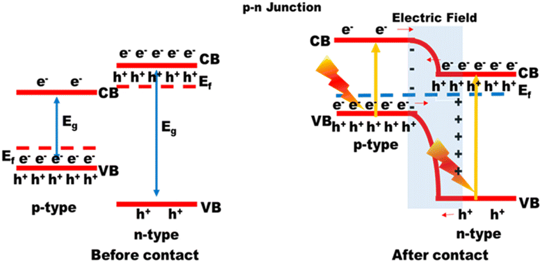 |
| | Fig. 33 Formation of heterojunctions between n-type and p-type semiconductors. | |
As illustrated in Fig. 34, Zhu et al. synthesized CoOx/g-C3N4, which upon annealing under vacuum conditions produced a type II hetero junction with well-dispersed nanoparticles of CoO on the surface of g-C3N4 nanotubes, whereas when annealed in the presence of air, Co3O4 nanoparticles of larger size with much aggregation were produced forming a type I heterojunction with g-C3N4 with a poor hydrogen yield as compared to the type II heterojunction formed material.229 Therefore, the type II heterojunction is the most effective approach, offering better photocatalytic activity due to efficient charge separation.
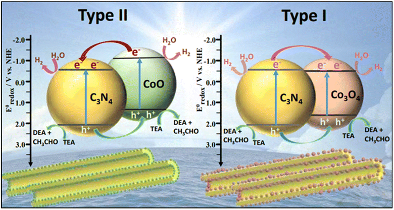 |
| | Fig. 34 Schematic diagram of type I and type II heterojunctions in CoOx/g-C3N4. Reproduced with permission Copyright 2019 ElsevierReproduced with permission. Copyright 2019 Elsevier.229 | |
When electrons from one semiconductor's CB interact with holes from another semiconductor's VB, another Z scheme can similarly be created. Recently, a series of developments have been made in the Z scheme approach for effective water splitting reactions. As illustrated in Fig. 35, Li et al.230 synthesized solid-state direct Z-scheme NiTiO3/Cd0.5Zn0.5S [as shown in Fig. 35(a)] with a hydrogen evolution rate of 26.45 mmol h−1 g−1, where electron transfer takes place from less CB negative NiTiO3 to a more VB positive Cd0.5Zn0.5S. Wang et al.231 also newly synthesized MoS2@In2S3/Bi2S3 that showed excellent dual Z-scheme photocatalytic hydrogen evolution at a higher rate of 973.42 μmol h−1 g−1. However previous reviews232 highlight some reports on the Z-scheme and type-II heterojunction, the former has serious, underlying issues and the latter is a broader area consisting of direct Z-scheme photocatalysts, indirect Z-scheme photocatalysts, and all-solid-state Z-scheme photocatalysts. The shortcomings of all-solid-state and conventional Z-scheme photocatalysts are transferred to direct Z-scheme photocatalysts, and both the approaches face serious recombination rates and low redox potentials. Therefore, a new S-type approach under type-II heterojunction can be developed addressing some of the drawbacks of previously reported approaches. Strong photogenerated electrons and holes are reserved in the CB of a lower negative CB potential material and the VB of a higher positive VB material, respectively, in an S-scheme heterojunction, whereas the ineffective photogenerated charge carriers are recombined and provide a strong redox potential.232 Following recent developments, Sun et al. reported233 S-scheme MnCo2S4/g-C3N4 [as shown in Fig. 35(b)] that showed an excellent hydrogen evolution rate of 2979 μmol g−1 h−1. Other than hydrogen generation, CO2 reduction was also followed by a noble S-scheme isotype 3D S-doped g-C3N4/2D O-doped g-C3N4 heterojunction by Qaraah et al.234 for enhanced production of methane. Moreover, Zhang et al.235 showed an advancement in the S-scheme approach by the construction of a 2D/3D S-scheme heterojunction interface of CeO2–Cu2O that promotes highly ordered charge transfer for efficient photocatalytic hydrogen evolution.
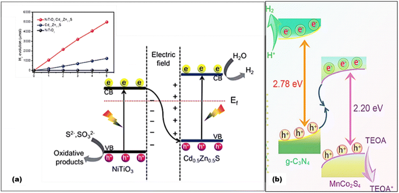 |
| | Fig. 35 (a) Schematic of Z-scheme NiTiO3/Cd0.5Zn0.5S showing an overall H2 evolution rate of 1058 mmol h−1. Reproduced with permission. Copyright 2021 Royal Society of Chemistry.230 (b) Schematic of S-Scheme MnCo2S4/g-C3N4 showing an overall H2 evolution rate of 2979 μmol g−1 h−1. Reproduced with permission. Copyright 2023 Chinese Chemical Society.233 | |
6.4. Surface modification
Surface modification is another strategy to achieve increased photocatalysis sites.61,236 By surface modification, first, the band gaps can be lowered for effective charge migration and second, the number of active sites for binding of reactant molecules for the photo-redox process increases, and it is by nature that by increasing the surface area, the catalytic activity can be increased.237 Moreover, with the increased surface area, porous materials show further increased binding sites for reactants. Therefore, materials like graphitic carbon nitrides, MOFs, COFs and many hierarchical porous materials surprisingly increase the overall photocatalytic activity. The probability of recombination can be decreased by shortening the band positions of smaller particles with higher crystallinity as a result of which photogenerated electrons and holes gets separated and the reaction active sites on the catalyst surface gets increased.238 The synthesis method used to generate the catalyst largely determines the structure of the photocatalyst. Yang et al.239 synthesized thermally oxidized porous g-C3N4 [Fig. 36(a)], which resulted in lower photoluminescence peaks with the increase in calcination temperature, as shown in Fig. 36(b), and produced 4.3 times higher 1430.1 μmol g−1 h−1 H2 than the pristine g-C3N4 which produced 334.3 μmol g−1 h−1 H2 [Fig. 36(c) and (d)]. Wang et al.240 used melamine and the nucleobases of biological reagents (adenine, guanine, cytosine, thymidine, and uracil) as precursors to produce g-C3N4 by a facile synthesis technique. With many binding sites provided by the nucleobase's good biological compatibility and hydrogen bonding propensity, g-C3N4 exhibits desired performance (5100.5 μmol g−1 h−1) when used as a precursor compared to typical molecules.
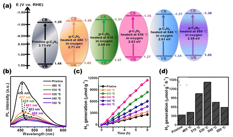 |
| | Fig. 36 (a) Schematic energy level diagrams of thermally oxidized and pristine g-C3N4 samples oxidized for 30 min at different temperatures. (b) PL intensities of different composites. (c) H2 evolution with respect to time. (d) H2 evolution in different composites. Reproduced with permission. Copyright 2017 Elsevier. | |
Zhang et al.241 synthesized porous MoS2/TiO2 nanosheets with surface partial oxidation using a hydrothermal technique followed by quenching, yielding 4669 μmol g−1 h−1, 5.8 times more than that of unquenched MoS2/TiO2. Using a novel phosphorization method, Cheng et al.242 synthesized nanosized MoP, which they subsequently combined with g-C3N4 to form a MoP/g-C3N4-linked photocatalyst by mixing and heat-treating. This method produced a corresponding AQY of 21.6% at 405 nm and showed a H2-production activity of 3868 μmol h−1 gcat−1. By using simple sonication, Zhao et al.243 synthesized MoS2/CdS [Fig. 37(a)] that demonstrated an exceptional H2 evolution rate of 71.24 mmol g−1 h−1, 13.39 times more than those of the comparable pristine CdS nanorods [Fig. 37(b)], which is largely due to CdS nanorods supported on rich active sites of MoS2 nanosheets, where the overall scheme is demonstrated in Fig. 37(c). ZnCo2S4/MOF-199 was synthesized by Dai et al.244 and shown strong photocatalytic activity, with an apparent quantum efficiency (AQY) of 4.92% at 420 nm as shown and an H2 evolution quantity of 11.6 mmol g−1 h−1, which is 48.4 and 83.3 times that of MOF-199 and ZCS, respectively.
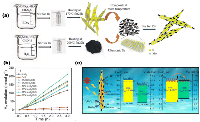 |
| | Fig. 37 (a) Synthesis route. (b) Hydrogen evolution rates. (c) Scheme of the photocatalytic HER in MoS2-200/TiO2. Reproduced with permission. Reproduced with permission. Copyright 2022 Elsevier.243 | |
6.5. Oxygen vacancies
Metal oxide semiconductors are commonly utilized for effective photocatalytic processes. They are made up of metal cations with d0 configuration.61,245 The high valence bands, however, are made up of O 2p orbitals, which inadequately absorb visible light and are situated at around +3 V with respect to NHE at pH 0. Because of their relatively accessible formation energy, typical oxygen vacancies in metal oxides develop readily in oxygen-deficient and reducing environments. These vacancies function as shallow donors above the valence band to narrow the bandgap. In order to create distinctive 2D holey defective TiO2 nanosheets (HD-TiO2 NSs) with plenty of oxygen vacancies for water splitting, Zhang et al.246 described a sacrificial template technique, where unique 2D holey defective TiO2 (HD-TiO2) was synthesized [as demonstrated in Fig. 38(a)] with ample oxygen vacancies consisting of a large number of mesoporous pores that provided tuned bandgap energies for different composites [Fig. 38(b)], which facilitates an excellent hydrogen production rate of 8.99 mmol g−1 h−1, 2.83 and 26.8 times higher than those of the H–TiO2 NSs catalyst and defected TiO2 bulk counterpart, respectively[Fig. 38(c) and (d)]. Its large number of mesopores made it easy to generate abundant oxygen vacancies.
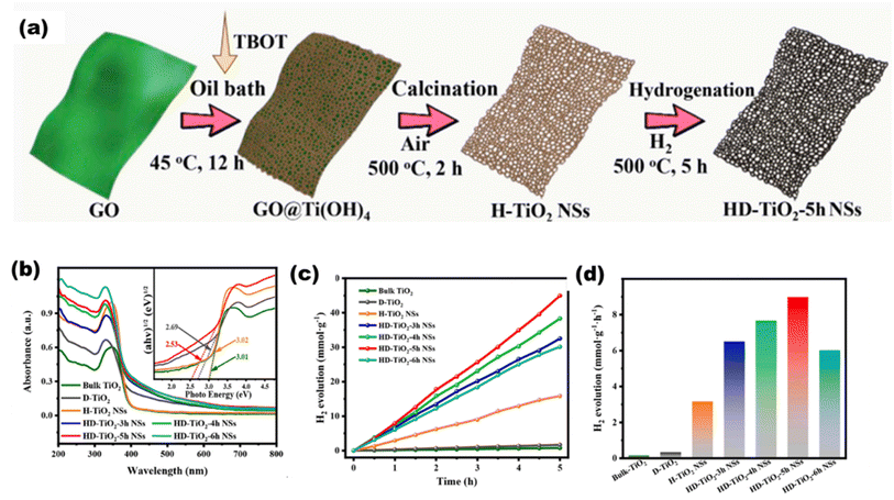 |
| | Fig. 38 (a) Schematic of the preparation, (b) UVDRS data showing bandgaps of different composites, HER with respect to (c) time and (d) different photocatalysts. Reproduced with permission. Copyright 2021 Elsevier.246 | |
Using synthetic black phosphorous, Gao et al.247 demonstrated how internal lattice strain caused by surface oxygen vacancies during the two-step aluminothermic reduction controls the band structure and improves the photoinduced charge behavior of black TiO2, as shown in Fig. 39(a). Under visible light illumination, the H2 production rates of black TiO2 with strain adjustment increase twelve times to 1.882 mmol g−1 h−1 with respect to time [Fig. 39(b)] and comparing other photocatalysts [Fig. 39(c)].
 |
| | Fig. 39 (a) Schematic showing four types of photocatalyst preparation. HER with respect to (b) time and (c) different photocatalysts. Reproduced with permission. Copyright 2021 American Chemical Society.247 | |
7. Construction of panels
Hydrogen is photogenerated from water via solar light absorbance of particulate photocatalysts. This setup uses redox mediators to keep the reduction and oxidation reactions close to one another. Particulate photocatalysts are used in the form of powder suspension, which is later designed for panels, and this is quite challenging. Unless the reactor is exactly levelled or agitated, photocatalyst particles concentrated in the lower portion of reactors cannot properly capture incident light. Moreover, it is difficult to construct an affordable device to support a significant quantity of H2O over a larger surface area. Even after lowering the depth of water to 1 cm, the weight of water in a rector was still 10 kg m−2.248 To support such a large load, a secure reactor must be constructed, and spreading a thin water layer across a wide region is not possible. Photocatalytic setups are normally carried out by distributing the photocatalyst powder in a reaction solution to achieve appropriate mass transfer.248 The photocatalytic setup and its inner layer on the glass substrate, as shown in Fig. 40, demonstrate a complete design of reactors and gas separation units. Ueda et al.221 have recently employed a 100 m2 array of Al-doped SrTiO3 photocatalyst sheets, which produced hydrogen over the course of several months by splitting water, with a maximum STH of 0.76%.
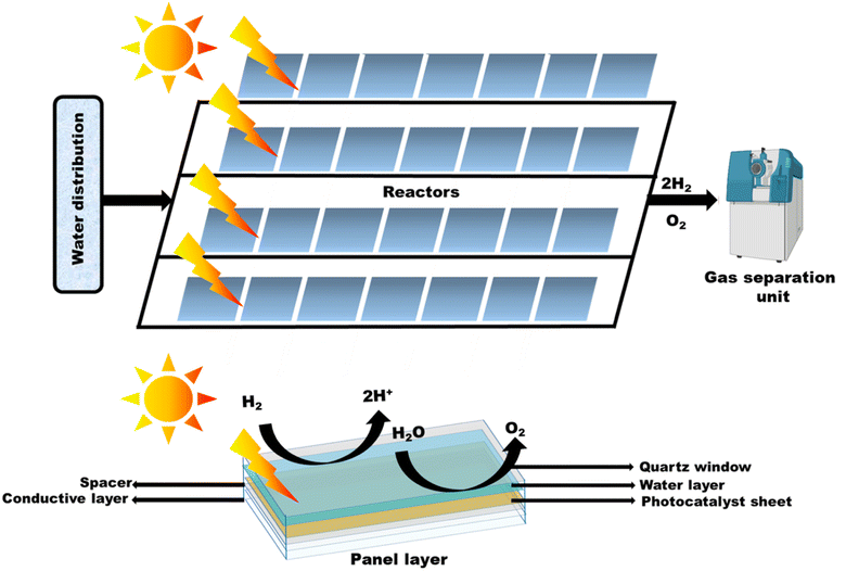 |
| | Fig. 40 Overall setup for the construction of panel and water evolution and schematic of the photocatalytic sheet preparation. | |
Moreover, due to simple handling and low-cost processes, photocatalysts exhibit a more enticing approach (as shown in Fig. 41) to producing H2 when compared to photovoltaic electrolysis (PV-EC) and photoelectrochemical (PEC) approaches. It is possible to avoid a complicated setup and the use of externally provided bias, which provides a method for producing H2 fuel that uses little energy. Particulate photocatalysis has been practiced in a powder suspension form for a long time. Developing particulate photocatalyst thin films with a localized photocatalyst powder on a substrate has recently showed a promising method for possible photocatalysis scaling.249
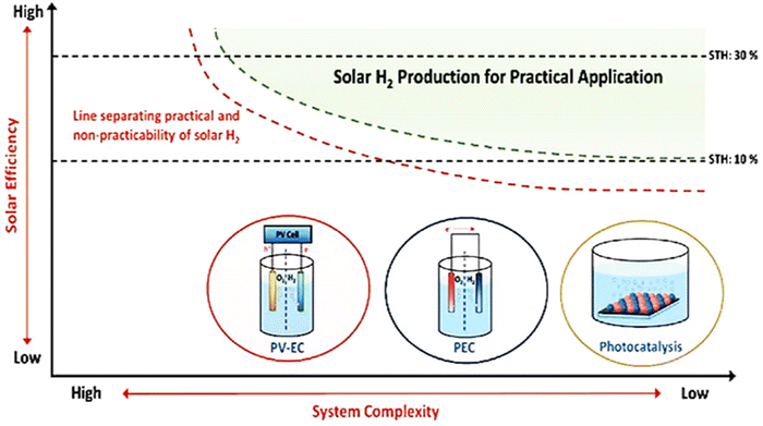 |
| | Fig. 41 Three distinct solar H2 manufacturing methods are shown on a conceptual map for realistic solar energy conversion. Reproduced with permission. Copyright 2020 Wiley.249,250 | |
Photocatalytic thin films can be designed using numerous techniques. One is drop-coating, as depicted in Fig. 42(a), where the precursor is dissolved in ethanol as the main solvent and Nafion, which acts as a polymer binder. In this process, the metal sheet is heated to 800 °C, and over it, a drop-coating of the as-prepared suspension is applied. Then, further drying is done at a reduced pressure at 800 °C for 24 hours to evaporate the solvents. Another typical approach for producing photocatalysts is to squeeze the photocatalyst power into a suspension of the precursor powder, 2,4-pentanedione, and Triton X in water. A glass rod is used to spread the slurry out on a FTO or ITO plate, compress it, and then calcine it at 673 K for an hour. If necessary, distilled water is added to the slurry of the photocatalyst with a silica powder, which is then dropped and dried at 323 K (by drop-casting). Introducing silica powder of a larger size, as shown in Fig. 42(b), makes the access of water inside the photocatalyst easier, which further splits into H2 and O2 molecules.
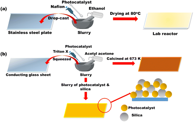 |
| | Fig. 42 (a) Drop-coating technique for panel preparation. (b) Representation of the squeeze technique for panel preparation. | |
However, the efficiency of many photocatalyst systems significantly decreases when scaling up to larger area production due to high charge recombination rates and lower light absorption efficiency. Some factors such as light harvestion, charge recombination, acidic pH, cost-effective cocatalyst loading, use of greener sacrificial agents, photocorrosion, and an environmentally friendly materials should be taken special care of during photocatalytic hydrogen production.153 It is anticipated that increasing the catalyst loading in the solution will be necessary for solar hydrogen production on a large scale.
7.1. Thin film approach for the preparation of panels
Solar cell construction using a thin film approach provides numerous applications in photocatalysis. The benefits of this preparation method include reduced material usage and flexible substrate use, but this is difficult to achieve with bulk materials. The type of deposition method to be used depends on the characteristics or activities of thin films. Due to their simplicity for use, low cost, and ability to deposit a range of materials, chemical-based techniques tend to be suitable for the coating of large-area thin sheets. To photogenerate green hydrogen on a large scale, lab-scale production must be expanded. There are a number of techniques for creating thin films of various sizes (cm2–m2), including screen printing, slot-die coating and spray coating, which are used to create films that are approximately 100 cm2 in size. Solar panels must be made under carefully controlled experimental circumstances in order to achieve high-quality thin sheets. High-quality thin films must be prepared since recombination will predominate if they lack proper light utilization. Basically in solar cells electrons have to travel over many microns to reach the back contact electrode. For sizes larger than 25 cm2, silver is mostly employed in the formation of thin films. Some literature reviews on thin film preparations are presented in the succeeding section.153 Therefore, using thin film approaches, numerous methods are listed as follows.
7.1.1. Drop-cast method.
Xiong et al.,251 drop-casted a Rh2−yCryO3/(Ga1−xZnx)(N1−xOx) slurry over a clean frosted glass plate (5 cm × 5 cm) and dried at 323 K. For uniform thickness of the film, the procedure was followed ten times. As illustrated in Fig. 43(a), a SiO2 powder with different sizes ranging from nanometer to meter was added to the slurry to make porous and hydrophilic thin sheets. The drop-casting technique was studied for a variety of substrate dimensions, including 3.5 × 3.5 × 0.25 cm3 for laboratory reactors and demonstrator reactors [as shown in Fig. 43(b)]. It was studied by Schröeder et al.169 for Pt@mp-CN photocatalysts using immobilized stainless steel plates. Photogenerated hydrogen is produced using photocatalyst panels under sunlight. It is significant to note that the platinum nanoparticles, which were produced independently by the micro-emulsion technique, were deposited on carbon nitride as a result of the negative zeta potentials of both CN and platinum.
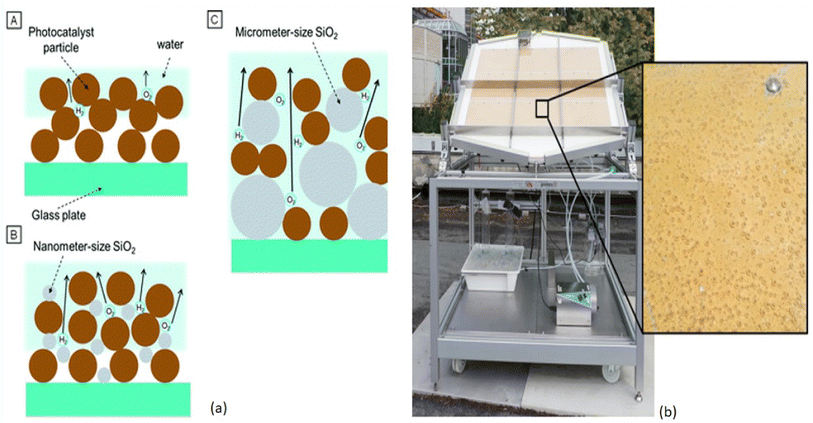 |
| | Fig. 43 (a) Photocatalyst panels prepared (A) without SiO2, (B) with nanometer-sized SiO2, and (C) with micrometer-sized SiO2. Reproduced with permission. Copyright 2014 Royal Society of Chemistry.251 (b) Large-scale photo-reactor; the magnification shows hydrogen bubbles emerging from the immobilized mesoporous carbon nitride photocatalyst. Reproduced with permission. Copyright 2015 Wiley.169 | |
Approaching an analogous technique to that reported by Schröeder et al.,169 Goto et al.268 presented a 1 m2 SrTiO3–Al panel [as shown in Fig. 44(a) and (b)] for large-scale hydrogen generation. The study placed a strong emphasis on a number of factors to enhance the performance of panel-type photocatalysts including a tilted angle of 10–20° and the layer of water with 1–5 mm width. These factors are crucial for reducing water pressure and weight in order to smoothly release gas bubbles. Hydrogen bubbles might be released from a layer of water just 1 mm deep without the need for forced convection.
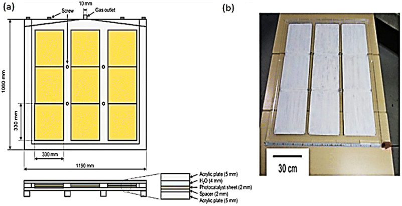 |
| | Fig. 44 (a) Schematics of the 1 × 1 m water-splitting panel, with 9 sheets arranged in an array. (b) Photograph of the SrTiO3:Al panel. Reproduced with permission. Copyright 2018 Joule.268 | |
By the drop-cast technique, thin-film TiO2 (different sizes and areas) photocatalysts (Pd/P25) were prepared by Nalajala et al.252 and employed for light harvesting, using palladium as a co-catalyst and methyl alcohol as a sacrificial agent. For uniform dispersion of the photocatalyst, 1 mg of Pd/P25 was added to 1 μl of ethanol and sonicated for 30 minutes. Using a 100 ml micropipette, catalyst dispersion was drop-casted onto a glass plate and allowed to dry for 12 hours at room temperature. Additionally, larger thin films were produced, as illustrated in Fig. 45.
 |
| | Fig. 45 Illustration of photocatalyst sheets printed on glass plates via a particle transfer method. | |
7.1.2. Screen printing.
Large-scale thin films are produced by screen printing with the highest possible material efficiency. The drying or sintering processes, not the screen printing method itself, control the production capacity. Hue et al.253 demonstrated the screen printing approach [as shown in Fig. 46] to produce a 10 × 10 cm2 sheet with a QE of 10% and was found to be stable in the presence of light for 1000 hours, under outdoor conditions for 30 days, and in one-year shelf life storage stability.153
 |
| | Fig. 46 Illustration of the screen printing technique over FTO glass. Reproduced with permission. Copyright 2017 Wiley.253 | |
Similar large-scale thin films were developed by Wang et al.254 in ethanol by combining SrTiO3:La,RhBiVO4:Mo powder, gold colloid, and organic binder to produce a printing ink. The ink was further screen printed on an ITO plate of 3 × 3 cm2 (ref. 255) soon after the evaporation of ethanol. Additionally, using this technique, 10 × 10 cm2 photocatalyst sheets were produced with different weight percentages of gold (40 wt%).
7.1.3. Particle transfer method.
The particle transfer method was used to produce thin films from powder catalyst suspensions. Wang et al.254 adopted and documented this technique for the preparation of SrTiO3:La, Rh, Au, and BiVO4 systems, as shown in Fig. 47(a) to (i). In between BiVO4 and SrTiO3:La, Rh, gold was used as the conduction layer, and Ag, Ni, Rh or Al can also be used as the conduction layer. However, the biggest concern with this method is the possibility of disturbing thin sheets when removing the main glass substrate. In order to increase conductivity between HEP and OEP, the metal conduction layer must be developed with sophisticated equipment.153,256
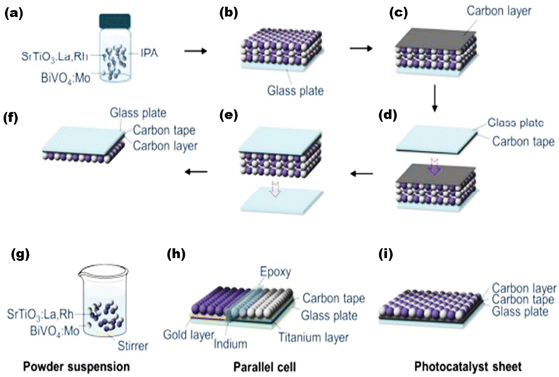 |
| | Fig. 47 (a)–(i) Schematic of the preparation of SrTiO3:La,Rh/C/BiVO4:Mo sheets through particle transfer. Reproduced with permission. Copyright 2017 American Chemical Society.254 | |
7.1.4. Doctor blade method.
To produce dye-sensitized solar cells (DSSCs), wide-band semiconductor layers are evenly coated using the doctor blade method. A thoroughly mixed slurry of photocatalyst substrate is dissolved in a solvent along with additives (such as cellulose) and applied to FTO or ITO. After calcination and drying, slurry is placed onto the glass plate to form an ideal thin layer, which is then continually pushed across by the doctor blade method. The necessary thickness of thin films is in the micron range and production depends on the quantity of material, area of the glass plate, and the speed of the doctor blade movement. With the proper use of solvents and additives in a suspension ideally, thin films of superior quality can be created. According to Patra et al.,257 a quasi-artificial leaf device was made utilising AuTiO2 thin sheets. Chalcogenides (CdS, PbS, and ZnS) were then used to sensitise the device. A single monolayer of CdS photocatalyst can be created in TiO2 pores by immersing mesoporous TiO2 sheets made by the doctor blade method in a Cd(NO3)2 solution, followed by a sodium solution.257
A limited number of cycles of this method can be used to create well-defined quantum dots with fixed diameters. Additionally, it produces a superior heterojunction between a titania substrate and CdS. In fact, this creates a possibility for the in situ assembly of light-harvesting quantum dots in the host material's pores.153
7.2. Recent developments combining the studies of overall photocatalytic water splitting and thin-film panel designing
Extensive research is ongoing to investigate the encouraging factors to enhance the effectiveness of solar light-mediated panel-type setups for scalable photocatalytic hydrogen production. As discussed earlier by Gopinath et al.,153 a thin film approach for panel construction seems to be beneficial due to several reasons compared to other approaches. By thin-film panel construction, the photocatalyst is entirely exposed to the light source, which favors charge carrier generation, leading to an enhanced photocatalytic activity. Moreover, the construction of thin films requires much less material and provides a uniform thick surface to favor the activity, thus leading to minimum material, resulting in maximum activity. Thin films also require minimum energy implementation when compared to powder suspension where mechanical stirring and separation of the catalyst are not required. It also fastens the formation of hydrogen and oxygen bubbles, where the thickness of water layer (normally 1 mm) can be modified by reactor designing to avoid light scattering by the bubbles over the surface of the catalyst. Further light exposure can also be increased by adjusting and tilting the panels in certain angles in track with the solar radiations. However, some limiting factors such as charge separation, recombination rates, photostability, and photocatalytic efficiency hinder the advantage of using thin-film photocatalysts. It takes fractions of seconds, i.e. microseconds to seconds, for photo-REDOX reactions to occur and nanoseconds for photo-physical processes such as light absorption and recombination. Therefore, this stands to be the major concern for higher recombination rates, and such issues can be tackled by strategies such as introduction of quantum dots and two-dimensional nanomaterials.153 It is also important to note that in photo-physical processes, nanoscience has made a significant contribution to the rapid expansion of light-emitting applications. It is suitable to use specific synthesis techniques to produce bulk heterojunctions in a composite photocatalyst. Bulk heterojunctions can be produced via the SILAR (successful ionic layer adsorption and reaction) method, which assists in assembling QDs in the pores of broad bandgap materials. Basically, the photocatalytic efficiency decreases significantly while extending the scale of catalyst amount, which is largely due to decreased exposure and poor penetration of light to the catalyst surface. Thin film approach is a practical solution to this mechanism when compared to powder suspension to some extent only, and many precautions such as thickness, area of coating, and use of appropriate binder need several modifications. pH conditions are yet to explore area for water splitting reactions, since water splitting reactions are limited to acidic pH only and not to basic scale.153 Most recently, Salgaonkar et al.24 demonstrated a complete idea on the synthesis of BiVO4 quantum dot (BVQD)-integrated TiO2 by the SILAR (successive ionic layer adsorption and reaction) approach and prepared a thin-film photocatalyst of 1 cm2 area over FTO by the doctor blade approach [as shown in Fig. 48] that showed 31–38% solar-to-fuel efficiency (STFE) with a photon-to-chemical conversion TOF of 2.73 s−1, which was further used as a mimicking artificial leaf for the conversion of CO2 + H2O to some value-added products (VAPs).
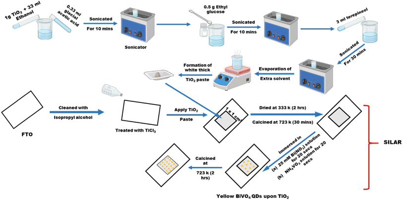 |
| | Fig. 48 Complete illustration of BVQD-integrated TiO2 over FTO for SWS. | |
Mani et al.258 synthesized a pristine mesoporous TiO2 and Ag/TiO2 nanocomposite and studied the photocatalytic activity of the thin film [as shown in Fig. 49] and powder form under solar light using 25% methanol solution. By loading 1 wt% Ag with the pristine form, a significant H2 yield was noted to ∼4.6 mmol h−1 g−1 with an AQE of 1.8 × 10⁻²%, which is largely due to the SPR effect of Ag. It is obvious that the thin film shows a higher yield as the catalysts comes in close contact and increases charge separation, transportation and surface active sites. Owing to the stability of the photocatalyst, a 23 mmol g−1 of H2 was produced in 5 h, which underwent five cycles of 5 h each. In this method only ethanol was used to disperse and make intact the catalyst in the panel, whereas further stability and activity can further be increased by adding any transparent binder or changing some method of preparation. Tudu et al.259 synthesized noble metal–free Cu, Ni bimetallic (1 wt%)-loaded TiO2 where Cu–Ni bimetal showed exceptional SPR effect with a favored photocatalytic activity, and the photocatalyst was further extended for H2 production reaction under solar light in both powder and thin-film forms. With a usual explanation, the thin-film catalyst showed an excellent hydrogen production rate of 41.7 mmol h−1 g−1 which is largely due to even and maximum exposure of light throughout the catalyst surface and improved charge separation at the interface of the catalyst. Tudu et al.260 earlier designed Au–Pd noble metals on carbon supported and integrated it upon TiO2 forming an Au–Pd/rGO/TiO2 nanocomposite. The nanocomposite was further employed to study the hydrogen evolution activity by drop-casting the photocatalyst upon a conducting glass substrate to an area of 1.25 cm × 3.75 cm that showed a hydrogen yield of 21.50 mmol h−1 g−1 and 0.50 mmol h−1 g−1 in a powder suspension, which practically proves the efficacy of the thin film approach.
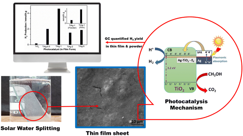 |
| | Fig. 49 Overall water splitting in a thin film of 1 wt% Ag–TiO2 photocatalyst. Reproduced with permission. Copyright 2022 Wiley.258 | |
Recently, Rajendran et al.261 have studied the photocatalytic property of a single metal cocatalyst with multiple oxidation states, where they synthesized a CuOx/TiO2 (Cun+ = + 1 or + 2) nanocomposite (one-pot method) using ethylene diamine tetra acetic acid (EDTA) and ethylene diamine as reagents where a suitable interfacial p–n heterojunction was formed that introduced higher photoinduced charge carrier separation and a higher charge transportation rate. Reported value shows that Cu in the + 1 oxidation state in the thin-film form showed a large hydrogen yield of 7.06 mmol h−1 g−1 when compared to its suspension form, which basically lacked light exposure and charge carrier activation.
Along with the method of preparation for photocatalyst films, the chemistry of choosing a good cocatalyst to further enhance the photocatalytic activity is another challenge; the cocatalyst at first must be cost-effective, earth-abundant and easily available, and hence, although noble metals are excellent co-catalysts due to their good localized surface plasmon effect, as discussed earlier in this paper, a non-noble metal co-catalyst can be a good strategy. In one of the study by Tudu et al.262 they specifically emphasized the role and availability of earth-abundant co-catalyst, where they synthesized Ni–Fe/TiO2 (3![[thin space (1/6-em)]](https://www.rsc.org/images/entities/char_2009.gif) :
:![[thin space (1/6-em)]](https://www.rsc.org/images/entities/char_2009.gif) 1) that showed a highest hydrogen evolution of 8.27 mmol h−1 g−1 in its thin films form under solar light, addition of co-catalyst and formation of thin film charge generation and separation, transportation and utilization was increased when compared to pristine TiO2 and powder suspension method. In photocatalysis for a better-reduced recombination rate, the transportation of electrons and holes to the reaction site is important. However, this property is hindered as recombination dominates, so using sacrificial agents can favour photooxidation that captures holes and exposes electrons for other half reactions. Generally, organic compounds such as alcohols, amines and sulphides69 play the role of a sacrificial agent, which has been covered in many above-discussed studies reported in the literature. The selection of sacrificial agent is not just arbitrary; rather, it is selected to ensure easy electron–hole transfer between light active photocatalysts and sacrificial reagents, possibly by matching their energy levels.153 Concerning this, the majority of chalcogenide-based photocatalysts use Na2S/Na2SO3, the most popular type of photocatalyst titania-based nanocomposites utilize alcohols such as methanol, ethanol, and glycerol, and graphitic carbon nitride, another fascinating class of photocatalysts, utilizes triethanol amine as a sacrificial agent for better hole utilisation. Lastly, the evolution of oxidized products such as carbon dioxide along with hydrogen production using a sacrificial agent should also be considered.153 However, replacing traditional organic compounds with greener compounds as sacrificial agents will lower the cost, minimize the harmfulness and increase the value, so extensive research in the use of sacrificial agents is required. Based on this, Bajpai et al.263 demonstrated photodeposited Au plasmonic nanoparticles upon TiO2 photocatalysts for hydrogen production using glycerol as a sacrificial agent which not only consumed the photogenerated holes but also underwent photooxidation to produce value-added products (VAPs) such as glycolaldehyde, dihydroxyacetone, and formic acid. When exposed to sun light, it produced 18 mmol h−1 g−1, which is the consequence of strong nano-heterojunction formed between Au and TiO2. Therefore, the entire hydrogen production process can be enhanced by certain photophysical and photochemical modifications, as discussed herein with an optimum loading amount of catalyst and careful choice of solvents and reaction conditions for use.
1) that showed a highest hydrogen evolution of 8.27 mmol h−1 g−1 in its thin films form under solar light, addition of co-catalyst and formation of thin film charge generation and separation, transportation and utilization was increased when compared to pristine TiO2 and powder suspension method. In photocatalysis for a better-reduced recombination rate, the transportation of electrons and holes to the reaction site is important. However, this property is hindered as recombination dominates, so using sacrificial agents can favour photooxidation that captures holes and exposes electrons for other half reactions. Generally, organic compounds such as alcohols, amines and sulphides69 play the role of a sacrificial agent, which has been covered in many above-discussed studies reported in the literature. The selection of sacrificial agent is not just arbitrary; rather, it is selected to ensure easy electron–hole transfer between light active photocatalysts and sacrificial reagents, possibly by matching their energy levels.153 Concerning this, the majority of chalcogenide-based photocatalysts use Na2S/Na2SO3, the most popular type of photocatalyst titania-based nanocomposites utilize alcohols such as methanol, ethanol, and glycerol, and graphitic carbon nitride, another fascinating class of photocatalysts, utilizes triethanol amine as a sacrificial agent for better hole utilisation. Lastly, the evolution of oxidized products such as carbon dioxide along with hydrogen production using a sacrificial agent should also be considered.153 However, replacing traditional organic compounds with greener compounds as sacrificial agents will lower the cost, minimize the harmfulness and increase the value, so extensive research in the use of sacrificial agents is required. Based on this, Bajpai et al.263 demonstrated photodeposited Au plasmonic nanoparticles upon TiO2 photocatalysts for hydrogen production using glycerol as a sacrificial agent which not only consumed the photogenerated holes but also underwent photooxidation to produce value-added products (VAPs) such as glycolaldehyde, dihydroxyacetone, and formic acid. When exposed to sun light, it produced 18 mmol h−1 g−1, which is the consequence of strong nano-heterojunction formed between Au and TiO2. Therefore, the entire hydrogen production process can be enhanced by certain photophysical and photochemical modifications, as discussed herein with an optimum loading amount of catalyst and careful choice of solvents and reaction conditions for use.
8. Conclusion
The production of green hydrogen as a fuel is a dire need to meet the global energy demands. This paper outlines all the factors, parameters and strategies responsible for increasing the overall photocatalytic activity, and the aim is to give a perspective and brief idea about the mechanism following photocatalytic water reduction and the role and category of nanomaterials in contributing for an enhanced photocatalytic activity. Out of all the discussed approaches, the photocatalytic system finds more reliability and scalability when compared to photovoltaic and photo-electrochemical systems; moreover, when the photocatalyst is in the form of thin films, the catalytic activity multiplies to a higher value than that of the powder suspension. The backbone of overall photocatalytic solar water splitting is the semiconducting photocatalyst substrate. Photocatalysts, whether in a powder suspension or as thin films, when exposed to light undergo redox reactions to produce hydrogen and oxygen simultaneously. Therefore, semiconductor photocatalysts with optimum band positions are largely responsible for scaling up hydrogen production, and various influential factors and strategies to utilize the catalyst were discussed, which will be beneficial to the readers to understand and design a suitable photocatalyst for water splitting reactions. Further, it is worth adding that a single photocatalyst system is not sufficient to utilize visible light and provide enough active sites for the binding of the substrate, and hence, to carry out the basic tasks of (a) light absorption and penetration from a varied range of visible light; (b) charge separation and transportation to surface active sites; and (c) oxygen evolution reactions (OERs) and hydrogen evolution reactions (HERs), fine tuning, structure modification, engineering and coupling is required. It is almost always a nanocomposite made up of at least two photocatalysts that further contributes to the catalytic activity by undergoing several strategic changes such as co-catalyst loading, doping, defect lowering, band gap engineering or hetero-junction formation to favor interfacial charge transfer. Herein, we have discussed a number of different photocatalysts that include metal oxides, metal chalcogenides, metal nitrides, graphitic carbon nitrides, COFs, MOFs, group III and V compounds, other noble metals, and plasmonic metals, and provided a general idea of choosing a suitable catalyst to design an ideal photocatalyst. By considering each of their QE, AQE, and hydrogen evolution rates, the photocatalytic activity of all categorized nanomaterials were brought to a context of comparison. A deep study of different photocatalyst substrates confirms that mostly covalent organic frameworks (COFs) due to their π–π stackings and layered ultrathin 2D structures showed the highest hydrogen evolution rates, which is largely due to the availability of π electrons and interfacial charge transfer between the layered structures; moreover, in metal organic frameworks (MOFs), photocatalytic activity was seen to be higher due to the availability of electron-rich longer ligands and electron-deficient metal sites, which gradually enhanced the electron transfer and separation in the highest occupied molecular orbital (HOMO) and lowest unoccupied molecular orbital (LUMO) of MOFs. However, to reach the maximum values, COFs and MOFs in their composite forms doubled the hydrogen production rates, which include the formation of a multicomponent photocatalyst, mainly a heterojunction or a core–shell structure. Similarly, metal oxides and other such photocatalysts, when joined through a heterojunction, give their best as a photocatalyst for visible light-sensitized water breakdown, which is largely due to charge separation, migration and transportation to a larger distance, lowering the chance of recombination. Such properties can be attained mainly by coupling a wide band gap semiconductor with a narrow band gap semiconductor. Another semiconductor was coupled as a photosensitizer, which provided the active sites for REDOX processes, or can act as the support to the base catalyst to improve the charge transfer distance. Another area of interest lies in the bottom study for the construction of thin-film panels, where the target will be mainly to scale up the arrays for larger areas with higher hydrogen evolution rates, as they grow from lab scale to commercial scale. This paper provides a distinct idea about several influential factors such as the method of preparation, catalyst coating amount, thickness of coating, area of exposure, angle of exposure, light penetration and absorption, recombination rates, acidic pH, cost-effective cocatalyst loading, use of greener sacrificial agents, photocorrosion, and eco-friendly precursors that primarily affect the evolution of hydrogen. In the secondary stage, panel preparation is another important factor because the fabrication method mainly determines the site of exposure of the photocatalyst substrate for effective light absorption. This is the reason for the advanced development of particulate photocatalyst sheets arranged in localized arrays rather than the use of a powder suspension for high hydrogen evolution rates on a large scale. The current evaluation covers a wide range of methodologies, with a brief focus on thin film-based techniques based on recent studies conducted by Gopinath et al.153 with enhanced solar hydrogen production in the thin-film form. We have also gone through a series of strategies based on various recent progresses in scaling up sheet arrays for larger areas based on the works of K. Domen et al.78 Apart from their activity, thin-film panels have already been claimed to be scalable, making them a better choice.248 In comparison to their powder counterparts, the sheets can produce approximately double the amount of hydrogen, which is reported in a series of works reported herein. Nevertheless, special care should be taken for overall water splitting and increasing STH. This is the leading advantage to photocatalysis: it can carry out the reactions under direct sunlight, which increases the temperature of the catalyst in solutions and efficiently affects the hydrogen evolution rates. The future perspective of the research is harvesting evolved green hydrogen for further in situ carbon dioxide reduction to generate numerous effective fuels by fine chemical synthesis via artificial photosynthetic routes.264–266 Photocatalytic nitrogen fixation using generated green hydrogen gives an alternative opportunity for industrial Haber's process in a green chemical method. Photocatalytic in situ hydrogen peroxide synthesis by the oxidation of water during green hydrogen generation paves the way for further several oxidation reactions. The utilization of the entire range of natural sun light153 is the focus of practical photocatalytic solar-powered systems. Despite numerous advances in photocatalytic water splitting currently, the synthesis of an ideal photocatalyst addressing all the influential parameters with an effective scaling approach is yet a question. This paper paves the way for finding ample solutions to these problems and designing a practical solar-powered system for green hydrogen generation.
Conflicts of interest
There are no conflicts to declare.
Acknowledgements
Authors are thankful to S‘O’A management for their constant support.
References
- C.-J. Winter, Int. J. Hydrogen Energy, 2005, 30, 681–685 CrossRef CAS
 .
.
- F. Zhang, P. Zhao, M. Niu and J. Maddy, Int. J. Hydrogen Energy, 2016, 41, 14535–14552 CrossRef CAS
 .
.
- J. O. M. Bockris, Int. J. Hydrogen Energy, 2013, 38, 2579–2588 CrossRef CAS
 .
.
- S. Sharma and S. K. Ghoshal, Renewable Sustainable Energy Rev., 2015, 43, 1151–1158 CrossRef CAS
 .
.
- J. Corredor, M. J. Rivero, C. M. Rangel, F. Gloaguen and I. Ortiz, J. Chem. Technol. Biotechnol., 2019, 94, 3049–3063 CrossRef CAS
 .
.
- A. Maroufmashat and M. Fowler, Energies, 2017, 10, 1089 CrossRef
 .
.
- A. Fujishima and K. Honda, Nature, 1972, 238, 37–38 CrossRef CAS PubMed
 .
.
- J. Qi, W. Zhang and R. Cao, Adv. Energy Mater., 2018, 8, 1701620 CrossRef
 .
.
- T. Hisatomi, J. Kubota and K. Domen, Chem. Soc. Rev., 2014, 43, 7520–7535 RSC
 .
.
- Y. Zhou, Y. Zhang, M. Lin, J. Long, Z. Zhang, H. Lin, J. C.-S. Wu and X. Wang, Nat. Commun., 2015, 6, 8340 CrossRef PubMed
 .
.
- H. Li, W. Tu, Y. Zhou and Z. Zou, Adv. Sci., 2016, 3, 1500389 CrossRef PubMed
 .
.
- P. Zhou, J. Yu and M. Jaroniec, Adv. Mater., 2014, 26, 4920–4935 CrossRef CAS PubMed
 .
.
- W.-Q. Tong, W.-N. Liu, J.-G. Cheng, P.-F. Zhang, G. Li, L. Hou and Y.-Y. Wang, Dalton Trans., 2018, 47, 9466–9473 RSC
 .
.
- K. Zhang and L. Guo, Catal. Sci. Technol., 2013, 3, 1672–1690 RSC
 .
.
- Z. Jiang, Y. Tang, Q. Tay, Y. Zhang, O. I. Malyi, D. Wang, J. Deng, Y. Lai, H. Zhou, X. Chen and others, Adv. Energy Mater., 2013, 3, 1368–1380 CrossRef CAS
 .
.
- C. Ding, J. Shi, Z. Wang and C. Li, ACS Catal., 2017, 7, 675–688 CrossRef CAS
 .
.
- M. R. Shaner, H. A. Atwater, N. S. Lewis and E. W. McFarland, Energy Environ. Sci., 2016, 9, 2354–2371 RSC
 .
.
-
H. B. Gray, in Abstracts of Papers of the American Chemical Society, 2015, vol. 249, p. COMSCI-1 Search PubMed
 .
.
- X. Yu, P. Yang, S. Chen, M. Zhang and G. Shi, Adv. Energy Mater., 2017, 7, 1601805 CrossRef
 .
.
- Q. Wang and K. Domen, Chem. Rev., 2019, 120, 919–985 CrossRef PubMed
 .
.
-
R. Li and C. Li, in Advances in Catalysis, Elsevier, 2017, vol. 60, pp. 1–57 Search PubMed
 .
.
-
Z. Chen, H. N. Dinh, E. Miller and others, Photoelectrochemical Water Splitting, Springer, 2013, vol. 344 Search PubMed
 .
.
- J. C. G. Bünzli, New J. Chem., 2011, 35, 1165–1176 RSC
 .
.
- K. N. Salgaonkar, H. Bajpai, N. B. Mhamane, N. Nalajala, I. Chauhan, K. Thakkar, K. Joshi and C. S. Gopinath, J. Mater. Chem. A, 2023, 11, 15168–15182 RSC
 .
.
- S. Oros-Ruiz, A. Hernández-Gordillo, C. Garcia-Mendoza, A. A. Rodriguez-Rodriguez and R. Gómez, J. Chem. Technol. Biotechnol., 2016, 91, 2205–2210 CrossRef CAS
 .
.
- F. Mei, J. Zhang, K. Dai, G. Zhu and C. Liang, Dalton Trans., 2019, 48, 1067–1074 RSC
 .
.
- C. Garcia-Mendoza, S. Oros-Ruiz, S. Ramirez-Rave, G. Morales-Mendoza, R. López and R. Gómez, J. Chem. Technol. Biotechnol., 2017, 92, 1503–1510 CrossRef CAS
 .
.
- D. Guerrero-Araque, P. Acevedo-Peña, D. Ramirez-Ortega, L. Lartundo-Rojas and R. Gómez, J. Chem. Technol. Biotechnol., 2017, 92, 1531–1539 CrossRef CAS
 .
.
- Y. Liu, G. Xu and H. Lv, J. Mater. Sci.: Mater. Electron., 2018, 29, 10504–10516 CrossRef CAS
 .
.
- W. Wen, Z. Lou, Y. Chen, D. Chen, S. Tian and Y. Xiong, J. Chem. Technol. Biotechnol., 2019, 94, 1576–1584 CrossRef CAS
 .
.
- D. R. Baker and P. V Kamat, Adv. Funct. Mater., 2009, 19, 805–811 CrossRef CAS
 .
.
- C. Wang, R. L. Thompson, P. Ohodnicki, J. Baltrus and C. Matranga, J. Mater. Chem., 2011, 21, 13452–13457 RSC
 .
.
- Q. Xu, L. Zhang, J. Yu, S. Wageh, A. A. Al-Ghamdi and M. Jaroniec, Mater. Today, 2018, 21, 1042–1063 CrossRef CAS
 .
.
- Z. Jin, X. Zhang, G. Lu and S. Li, J. Mol. Catal. A: Chem., 2006, 259, 275–280 CrossRef CAS
 .
.
- R. Abe, K. Sayama and H. Arakawa, J. Photochem. Photobiol., A, 2004, 166, 115–122 CrossRef CAS
 .
.
- S.-Y. Lee and S.-J. Park, J. Ind. Eng. Chem., 2013, 19, 1761–1769 CrossRef CAS
 .
.
- D. Kandi, S. Martha and K. M. Parida, Int. J. Hydrogen Energy, 2017, 42, 9467–9481 CrossRef CAS
 .
.
- C. Acar, I. Dincer and C. Zamfirescu, Int. J. Energy Res., 2014, 38, 1903–1920 CrossRef CAS
 .
.
- A. A. Melvin, K. Illath, T. Das, T. Raja, S. Bhattacharyya and C. S. Gopinath, Nanoscale, 2015, 7, 13477–13488 RSC
 .
.
- N. S. Lewis and D. G. Nocera, Proc. Natl. Acad. Sci. U. S. A., 2006, 103, 15729–15735 CrossRef CAS PubMed
 .
.
- K. Maeda, J. Photochem. Photobiol., C, 2011, 12, 237–268 CrossRef CAS
 .
.
- J.-Y. Cho, H. Kim, J.-E. Oh and B. Y. Park, Catalysts, 2021, 11, 1497 CrossRef CAS
 .
.
- R. H. Crabtree, Energy Environ. Sci., 2008, 1, 134–138 RSC
 .
.
- M. Kirch, J.-M. Lehn and J.-P. Sauvage, Helv. Chim. Acta, 1979, 62, 1345–1384 CrossRef CAS
 .
.
- G. M. Brown, B. S. Brunschwig, C. Creutz, J. F. Endicott and N. Sutin, J. Am. Chem. Soc., 1979, 101, 1298–1300 CrossRef CAS
 .
.
- Y. Chen, Z. Qin, X. Wang, X. Guo and L. Guo, RSC Adv., 2015, 5, 18159–18166 RSC
 .
.
- R. S. Khnayzer, V. S. Thoi, M. Nippe, A. E. King, J. W. Jurss, K. A. El Roz, J. R. Long, C. J. Chang and F. N. Castellano, Energy Environ. Sci., 2014, 7, 1477–1488 RSC
 .
.
- M. Wang, K. Han, S. Zhang and L. Sun, Coord. Chem. Rev., 2015, 287, 1–14 CrossRef CAS
 .
.
- S. Berardi, S. Drouet, L. Francàs, C. Gimbert-Suriñach, M. Guttentag, C. Richmond, T. Stoll and A. Llobet, Chem. Soc. Rev., 2014, 43, 7501–7519 RSC
 .
.
- W.-G. Wang, F. Wang, H.-Y. Wang, G. Si, C.-H. Tung and L.-Z. Wu, Chem.–Asian J., 2010, 5, 1796–1803 CrossRef CAS PubMed
 .
.
- S. Gao, W.-Y. Zhang, Q. Duan, Q.-C. Liang, D.-Y. Jiang, J.-X. Zhao and J.-H. Hou, Chem. Pap., 2017, 71, 617–625 CrossRef CAS
 .
.
- H.-Y. Wang, W.-G. Wang, G. Si, F. Wang, C.-H. Tung and L.-Z. Wu, Langmuir, 2010, 26, 9766–9771 CrossRef CAS PubMed
 .
.
- F. Quentel, G. Passard and F. Gloaguen, Chem. - Eur. J., 2012, 18, 13473–13479 CrossRef CAS PubMed
 .
.
- M. A. Waghmare, K. S. Pawar, H. M. Pathan and A. U. Ubale, Mater. Sci. Semicond. Process., 2017, 72, 122–127 CrossRef CAS
 .
.
- P. Yang, Z.-J. Zhao, X. Chang, R. Mu, S. Zha, G. Zhang and J. Gong, Angew. Chem., 2018, 130, 7850–7854 CrossRef
 .
.
- W.-T. Chen, A. Chan, Z. H. N. Al-Azri, A. G. Dosado, M. A. Nadeem, D. Sun-Waterhouse, H. Idriss and G. I. N. Waterhouse, J. Catal., 2015, 329, 499–513 CrossRef CAS
 .
.
- M. Ismael, New J. Chem., 2019, 43, 9596–9605 RSC
 .
.
- A. Chachvalvutikul, T. Luangwanta, S. Pattisson, G. J. Hutchings and S. Kaowphong, Appl. Surf. Sci., 2021, 544, 148885 CrossRef CAS
 .
.
- X. Jiang, H. Gong, Q. Liu, M. Song and C. Huang, Appl. Catal., B, 2020, 268, 118439 CrossRef CAS
 .
.
- Y. Gao, K. Qian, B. Xu, F. Ding, V. Dragutan, I. Dragutan, Y. Sun and Z. Xu, RSC Adv., 2020, 10, 32652–32661 RSC
 .
.
- N. Fajrina and M. Tahir, Int. J. Hydrogen Energy, 2019, 44, 540–577 CrossRef CAS
 .
.
- L. Clarizia, D. Spasiano, I. Di Somma, R. Marotta, R. Andreozzi and D. D. Dionysiou, Int. J. Hydrogen Energy, 2014, 39, 16812–16831 CrossRef CAS
 .
.
- Y. Wu, G. Lu and S. Li, Catal. Lett., 2009, 133, 97–105 CrossRef CAS
 .
.
- R. Brahimi, Y. Bessekhouad, A. Bouguelia and M. Trari, J. Photochem. Photobiol., A, 2007, 186, 242–247 CrossRef CAS
 .
.
- H. Ahmad, S. K. Kamarudin, L. J. Minggu and M. Kassim, Renewable Sustainable Energy Rev., 2015, 43, 599–610 CrossRef CAS
 .
.
- J. J. Velázquez, R. Fernández-González, L. Diaz, E. P. Melián, V. D. Rodriguez and P. Núñez, J. Alloys Compd., 2017, 721, 405–410 CrossRef
 .
.
- S. Fang, Z. Sun and Y. H. Hu, ACS Catal., 2019, 9, 5047–5056 CrossRef CAS
 .
.
- J. A. O. Méndez, C. R. López, E. P. Melián, O. G. Diaz, J. M. D. Rodriguez, D. F. Hevia and M. Macias, Appl. Catal., B, 2014, 147, 439–452 CrossRef
 .
.
- V. Kumaravel, M. D. Imam, A. Badreldin, R. K. Chava, J. Y. Do, M. Kang and A. Abdel-Wahab, Catalysts, 2019, 9, 276 CrossRef CAS
 .
.
- W.-T. Chen, Y. Dong, P. Yadav, R. D. Aughterson, D. Sun-Waterhouse and G. I. N. Waterhouse, Appl. Catal., A, 2020, 602, 117703 CrossRef CAS
 .
.
- L. Wang, X. Geng, L. Zhang, Z. Liu, H. Wang and Z. Bian, Chemosphere, 2022, 286, 131558 CrossRef CAS PubMed
 .
.
- X. Chen, L. Liu and F. Huang, Chem. Soc. Rev., 2015, 44, 1861–1885 RSC
 .
.
- B. Sun, W. Zhou, H. Li, L. Ren, P. Qiao, W. Li and H. Fu, Adv. Mater., 2018, 30, 1804282 CrossRef PubMed
 .
.
- Y. Li, Z. Tang, J. Zhang and Z. Zhang, J. Phys. Chem. C, 2016, 120, 9750–9763 CrossRef CAS
 .
.
- A. Naldoni, M. Allieta, S. Santangelo, M. Marelli, F. Fabbri, S. Cappelli, C. L. Bianchi, R. Psaro and V. Dal Santo, J. Am. Chem. Soc., 2012, 134, 7600–7603 CrossRef CAS PubMed
 .
.
- X. Li, J. Yu, J. Low, Y. Fang, J. Xiao and X. Chen, J. Mater. Chem. A, 2015, 3, 2485–2534 RSC
 .
.
- S. Chen, T. Takata and K. Domen, Nat. Rev. Mater., 2017, 2, 1–17 Search PubMed
 .
.
- Z. Wang, C. Li and K. Domen, Chem. Soc. Rev., 2019, 48, 2109–2125 RSC
 .
.
- Z. Wang, T. Hisatomi, R. Li, K. Sayama, G. Liu, K. Domen, C. Li and L. Wang, Joule, 2021, 5, 344–359 CrossRef CAS
 .
.
-
J. R. Bolton, Solar photoproduction of hydrogen, IEA Technical Report of the IEA Agreement of the Production and Utilization of Hydrogen, 1996 Search PubMed
 .
.
- T. Hisatomi and K. Domen, Nat. Catal., 2019, 2, 387–399 CrossRef CAS
 .
.
- T. Setoyama, T. Takewaki, K. Domen and T. Tatsumi, Faraday Discuss., 2017, 198, 509–527 RSC
 .
.
- R. Levinson, H. Akbari and P. Berdahl, Sol. Energy, 2010, 84, 1745–1759 CrossRef
 .
.
- S. Martha, P. C. Sahoo and K. M. Parida, RSC Adv., 2015, 5, 61535–61553 RSC
 .
.
- S. Premi, S. Wallisch, C. M. Mano, A. B. Weiner, A. Bacchiocchi, K. Wakamatsu, E. J. H. Bechara, R. Halaban, T. Douki and D. E. Brash, Science, 2015, 347, 842–847 CrossRef CAS PubMed
 .
.
- S. Giannakis, S. Liu, A. Carratalà, S. Rtimi, M. T. Amiri, M. Bensimon and C. Pulgarin, J. Hazard. Mater., 2017, 339, 223–231 CrossRef CAS PubMed
 .
.
-
N. Nuraje, S. Kudaibergenov and R. Asmatulu, Prod. Fuels Fine Chem. From Biomass Using Nanomater., 2013, vol. 95 Search PubMed
 .
.
- J. Xing, W. Q. Fang, H. J. Zhao and H. G. Yang, Chem. - Asian J., 2012, 7, 642–657 CrossRef CAS PubMed
 .
.
- A. Naldoni, M. Altomare, G. Zoppellaro, N. Liu, S. Kment, R. Zboril and P. Schmuki, ACS Catal., 2018, 9, 345–364 CrossRef PubMed
 .
.
- H. Yamashita, M. Harada, J. Misaka, M. Takeuchi, K. Ikeue and M. Anpo, J. Photochem. Photobiol., A, 2002, 148, 257–261 CrossRef CAS
 .
.
- M. Anpo, Bull. Chem. Soc. Jpn., 2004, 77, 1427–1442 CrossRef CAS
 .
.
- M. Kitano, M. Matsuoka, M. Ueshima and M. Anpo, Appl. Catal., A, 2007, 325, 1–14 CrossRef CAS
 .
.
- J.-P. Jeon, D. H. Kweon, B. J. Jang, M. J. Ju and J.-B. Baek, Adv. Sustainable Syst., 2020, 4, 2000197 CrossRef CAS
 .
.
- M. de Respinis, M. Fravventura, F. F. Abdi, H. Schreuders, T. J. Savenije, W. A. Smith, B. Dam and R. van de Krol, Chem. Mater., 2015, 27, 7091–7099 CrossRef CAS
 .
.
- X. Gu, C. Tan, L. He, J. Guo, X. Zhao, K. Qi and Y. Yan, Chemosphere, 2022, 304, 135292 CrossRef CAS PubMed
 .
.
- M. Zhu, Y. Wang, Y.-H. Deng, X. Peng, X. Wang, H. Yuan, Z.-J. Yang, Y. Wang and H. Wang, Nanoscale, 2020, 12, 7035–7044 RSC
 .
.
- J. Ding, X. Li, L. Chen, X. Zhang and X. Tian, Appl. Catal., B, 2018, 224, 322–329 CrossRef CAS
 .
.
- K. Han, W. Li, C. Ren, H. Li, X. Liu, X. Li, X. Ma, H. Liu and A. Khan, J. Taiwan Inst. Chem. Eng., 2020, 112, 4–14 CrossRef CAS
 .
.
- Q. Tan, K. Li, Q. Li, Y. Ding, J. Fan, Z. Xu and K. Lv, Mater. Today Chem., 2022, 26, 101114 CrossRef CAS
 .
.
- J. Liu, G. Hodes, J. Yan and S. F. Liu, Chin. J. Catal., 2021, 42, 205–216 CrossRef CAS
 .
.
- S. Mohanty, P. Babu, K. Parida and B. Naik, Inorg. Chem., 2019, 58, 9643–9654 CrossRef CAS PubMed
 .
.
- S. Y. Moon, B. Naik, C.-H. Jung, K. Qadir and J. Y. Park, Catal. Today, 2016, 265, 245–253 CrossRef CAS
 .
.
- P. Babu and B. Naik, Inorg. Chem., 2020, 15, 10824 CrossRef PubMed
 .
.
- A. Dhakshinamoorthy, Z. Li and H. Garcia, Chem. Soc. Rev., 2018, 47, 8134–8172 RSC
 .
.
- Q. Wang, Q. Gao, A. M. Al-Enizi, A. Nafady and S. Ma, Inorg. Chem. Front., 2020, 7, 300–339 RSC
 .
.
- D. A. Reddy, Y. Kim, M. Gopannagari, D. P. Kumar and T. K. Kim, Sustainable Energy Fuels, 2021, 5, 1597–1618 RSC
 .
.
- J. He, Z. Yan, J. Wang, J. Xie, L. Jiang, Y. Shi, F. Yuan, F. Yu and Y. Sun, Chem. Commun., 2013, 49, 6761–6763 RSC
 .
.
- Y. Wang, Y. Zhang, Z. Jiang, G. Jiang, Z. Zhao, Q. Wu, Y. Liu, Q. Xu, A. Duan and C. Xu, Appl. Catal., B, 2016, 185, 307–314 CrossRef CAS
 .
.
- Z. Jin and H. Yang, Nanoscale Res. Lett., 2017, 12, 1–10 CrossRef CAS PubMed
 .
.
- D.-M. Chen, C.-X. Sun, C.-S. Liu and M. Du, Inorg. Chem., 2018, 57, 7975–7981 CrossRef CAS PubMed
 .
.
- C.-W. Zhao, Y.-A. Li, X.-R. Wang, G.-J. Chen, Q.-K. Liu, J.-P. Ma and Y.-B. Dong, Chem. Commun., 2015, 51, 15906–15909 RSC
 .
.
- S. Mao, J.-W. Shi, G. Sun, Y. Zhang, X. Ji, Y. Lv, B. Wang, Y. Xu and Y. Cheng, Chem. Eng. J., 2021, 404, 126533 CrossRef CAS
 .
.
- Z. Jin, H. Gong and L. Hongying, ACS Appl. Mater. Interfaces, 2021, 603, 344–355 CAS
 .
.
- Q. Yang, M. Luo, K. Liu, H. Cao and H. Yan, Appl. Catal., B, 2020, 276, 119174 CrossRef CAS
 .
.
- C.-C. Gu, F.-H. Xu, W.-K. Zhu, R.-J. Wu, L. Deng, J. Zou, B.-C. Weng and R.-L. Zhu, Chem. Commun., 2023, 59, 7302–7320 RSC
 .
.
- Y. Chen, D. Yang, B. Shi, W. Dai, H. Ren, K. An, Z. Zhou, Z. Zhao, W. Wang and Z. Jiang, J. Mater. Chem. A, 2020, 8, 7724–7732 RSC
 .
.
- T. Zhou, X. Huang, Z. Mi, Y. Zhu, R. Wang, C. Wang and J. Guo, Polym. Chem., 2021, 12, 3250–3256 RSC
 .
.
- J. Yang, A. Acharjya, M.-Y. Ye, J. Rabeah, S. Li, Z. Kochovski, S. Youk, J. Roeser, J. Grüneberg, C. Penschke and others, Angew. Chem., Int. Ed., 2021, 60, 19797–19803 CrossRef CAS PubMed
 .
.
- N. Xu, Y. Liu, W. Yang, J. Tang, B. Cai, Q. Li, J. Sun, K. Wang, B. Xu, Q. Zhang and others, ACS Appl. Energy Mater., 2020, 3, 11939–11946 CrossRef CAS
 .
.
- C. Liu, Y. Xiao, Q. Yang, Y. Wang, R. Lu, Y. Chen, C. Wang and H. Yan, Appl. Surf. Sci., 2021, 537, 148082 CrossRef CAS
 .
.
- S. Ma, T. Deng, Z. Li, Z. Zhang, J. Jia, Q. Li, G. Wu, H. Xia, S.-W. Yang and X. Liu, Angew. Chem., 2022, 134, e202208919 CrossRef
 .
.
- P. Dong, T. Cheng, J. Zhang, J. Jiang, L. Zhang, X. Xi and J. Zhang, ACS Appl. Energy Mater., 2023, 6, 1103–1115 CrossRef CAS
 .
.
- K. Maeda, X. Wang, Y. Nishihara, D. Lu, M. Antonietti and K. Domen, J. Phys. Chem., 2009, 12, 4940–4947 Search PubMed
 .
.
- T. Liu, G. Yang, W. Wang, C. Wang, M. Wang, X. Sun, P. Xu and J. Zhang, Environ. Res., 2020, 188, 109741 CrossRef CAS PubMed
 .
.
- G. Zhang, Z.-A. Lan, L. Lin, S. Lin and X. Wang, Chem. Sci., 2016, 7, 3062–3066 RSC
 .
.
- C. Hu, Y.-H. Lin, M. Yoshida and S. Ashimura, ACS Appl. Mater. Interfaces, 2021, 13, 24907–24915 CrossRef CAS PubMed
 .
.
- Y. Zhang, T. Mori, J. Ye and M. Antonietti, J. Am. Chem. Soc., 2010, 132, 6294–6295 CrossRef CAS PubMed
 .
.
- X. Chang, H. Fan, S. Zhu, L. Lei, X. Wu, C. Feng, W. Wang and L. Ma, Ceram. Int., 2023, 49, 6729–6738 CrossRef CAS
 .
.
- C. Cheng, J. Shi, L. Mao, C.-L. Dong, Y.-C. Huang, S. Zong, J. Liu, S. Shen and L. Guo, J. Colloid Interface Sci., 2023, 637, 271–282 CrossRef CAS PubMed
 .
.
- Z. Wang, Y. Inoue, T. Hisatomi, R. Ishikawa, Q. Wang, T. Takata, S. Chen, N. Shibata, Y. Ikuhara and K. Domen, Nat. Catal., 2018, 1, 756–763 CrossRef CAS
 .
.
- H. Y. Hafeez, J. Mohammad, A. B. Suleiman, C. E. Ndikilar, R. S. Said and I. Muhammad, Chem. Phys. Impact, 2022, 100157 Search PubMed
 .
.
- T. Takata, J. Jiang, Y. Sakata, M. Nakabayashi, N. Shibata, V. Nandal, K. Seki, T. Hisatomi and K. Domen, Nature, 2020, 581, 411–414 CrossRef CAS PubMed
 .
.
- Q. Wang, S. Kalathil, C. Pornrungroj, C. D. Sahm and E. Reisner, Nat. Catal., 2022, 5, 633–641 CrossRef CAS
 .
.
- Q.-Y. Liu, Y. Zhong, Z.-Z. Jiang, K. Chen, S. Ma, P.-F. Wang, W. Wang, L. Zhou, M.-D. Luoshan and Q.-Q. Wang, J. Mater. Chem. C, 2020, 8, 4869–4875 RSC
 .
.
- Q.-Y. Liu, Y. Zhong, Z.-Z. Jiang, K. Chen, S. Ma, P.-F. Wang, W. Wang, L. Zhou, M.-D. Luoshan and Q.-Q. Wang, J. Mater. Chem. C, 2020, 8, 4869–4875 RSC
 .
.
- L. K. Preethi, R. P. Antony, T. Mathews, L. Walczak and C. S. Gopinath, Sci. Rep., 2017, 7, 14314 CrossRef CAS PubMed
 .
.
- M. Chauhan, K. Soni, P. E. Karthik, K. P. Reddy, C. S. Gopinath and S. Deka, J. Mater. Chem. A, 2019, 7, 6985–6994 RSC
 .
.
- D. K. Chauhan, V. R. Battula, S. Jain and K. Kailasam, J. Cleaner Prod., 2021, 307, 127162 CrossRef CAS
 .
.
- B. Naik, S. Y. Moon, S. H. Kim and J. Y. Park, Appl. Surf. Sci., 2015, 354, 347–352 CrossRef CAS
 .
.
- K. K. Patra and C. S. Gopinath, ChemCatChem, 2016, 8, 3294–3311 CrossRef CAS
 .
.
- N. Pradhan, S. Das Adhikari, A. Nag and D. D. Sarma, Angew. Chem., Int. Ed., 2019, 56, 7038–7054 CrossRef PubMed
 .
.
- P. Babu and B. Naik, Inorg. Chem., 2020, 59, 10824–10834 CrossRef CAS PubMed
 .
.
- M. Zheng, Y. Ding, L. Yu, X. Du and Y. Zhao, Adv. Funct. Mater., 2017, 27, 1605846 CrossRef
 .
.
- A. Machin, M. Cotto, J. Duconge, J. C. Arango, C. Morant, S. Pinilla, L. Soto-Vázquez, E. Resto and F. Márquez, J. Photochem. Photobiol., A, 2018, 353, 385–394 CrossRef CAS
 .
.
- X. Yin, X. Li, H. Liu, W. Gu, W. Zou, L. Zhu, Z. Fu and Y. Lu, Nano Energy, 2018, 49, 489–497 CrossRef CAS
 .
.
- Z. Zhang, Y. Zhu, X. Chen, H. Zhang and J. Wang, Adv. Mater., 2019, 31, 1806626 CrossRef PubMed
 .
.
- K. M. Parida, S. Pany and B. Naik, Int. J. Hydrogen Energy, 2013, 38, 3545–3553 CrossRef CAS
 .
.
- A. M. Huerta-Flores, L. M. Torres-Martinez and E. Moctezuma, Int. J. Hydrogen Energy, 2017, 42, 14547–14559 CrossRef CAS
 .
.
- S. Pany, B. Naik, S. Martha and K. Parida, ACS Appl. Mater. Interfaces, 2014, 6, 839–846 CrossRef CAS PubMed
 .
.
- G. Swain, S. Sultana, B. Naik and K. Parida, ACS Omega, 2017, 2, 3745–3753 CrossRef CAS PubMed
 .
.
- H. Tian, X.-F. Wang, M. A. Mohammad, G.-Y. Gou, F. Wu, Y. Yang and T.-L. Ren, Nat. Commun., 2018, 9, 4305 CrossRef PubMed
 .
.
- M. M. Momeni and Y. Ghayeb, J. Appl. Electrochem., 2015, 45, 557–566 CrossRef CAS
 .
.
- C. S. Gopinath and N. Nalajala, J. Mater. Chem. A, 2021, 9, 1353–1371 RSC
 .
.
- L. Liao, Q. Zhang, Z. Su, Z. Zhao, Y. Wang, Y. Li, X. Lu, D. Wei, G. Feng, Q. Yu and others, Nat. Nanotechnol., 2014, 9, 69–73 CrossRef CAS PubMed
 .
.
- P. Dhanasekaran and N. M. Gupta, Int. J. Hydrogen Energy, 2012, 37, 4897–4907 CrossRef CAS
 .
.
- G.-J. Lee, Y.-C. Zheng and J. J. Wu, Catal. Today, 2018, 307, 197–204 CrossRef CAS
 .
.
- Y. Zhang and S.-J. Park, J. Catal., 2017, 355, 1–10 CrossRef CAS
 .
.
- W. Chen, H. Liu, X. Li, S. Liu, L. Gao, L. Mao, Z. Fan, W. Shangguan, W. Fang and Y. Liu, Appl. Catal., B, 2016, 192, 145–151 CrossRef CAS
 .
.
- Q. Jia, A. Iwase and A. Kudo, Chem. Sci., 2014, 5, 1513–1519 RSC
 .
.
- C. M. Wolff, P. D. Frischmann, M. Schulze, B. J. Bohn, R. Wein, P. Livadas, M. T. Carlson, F. Jäckel, J. Feldmann, F. Würthner and others, Nat. Energy, 2018, 3, 862–869 CrossRef CAS
 .
.
- L. Luo and P. A. Maggard, Cryst. Growth Des., 2013, 13, 5282–5288 CrossRef CAS
 .
.
- C. Pan, T. Takata, M. Nakabayashi, T. Matsumoto, N. Shibata, Y. Ikuhara and K. Domen, Angew. Chem., Int. Ed., 2015, 54, 2955–2959 CrossRef CAS PubMed
 .
.
- M. Manikandan, T. Tanabe, P. Li, S. Ueda, G. V Ramesh, R. Kodiyath, J. Wang, T. Hara, A. Dakshanamoorthy, S. Ishihara and others, ACS Appl. Mater. Interfaces, 2014, 6, 3790–3793 CrossRef CAS PubMed
 .
.
- W. Shi, F. Guo, H. Wang, M. Han, H. Li, S. Yuan, H. Huang, Y. Liu and Z. Kang, Appl. Catal., B, 2017, 219, 36–44 CrossRef CAS
 .
.
- T. Oshima, D. Lu, O. Ishitani and K. Maeda, Angew. Chem., 2015, 127, 2736–2740 CrossRef
 .
.
- L. LiuJuan, Science, 2015, 347, 970r974 Search PubMed
 .
.
- L. Chen, Y. Xu, Z. Yang, K. Zhang and B. Chen, Appl. Catal., B, 2020, 277, 119207 CrossRef CAS
 .
.
- P. Babu, S. Mohanty, B. Naik and K. Parida, ACS Appl. Energy Mater., 2018, 1, 5936–5947 CrossRef CAS
 .
.
- M. Schröder, K. Kailasam, J. Borgmeyer, M. Neumann, A. Thomas, R. Schomäcker and M. Schwarze, Energy Technol., 2015, 3, 1014–1017 CrossRef
 .
.
- B. Yue, Q. Li, H. Iwai, T. Kako and J. Ye, Sci. Technol. Adv. Mater., 2011, 034401 CrossRef PubMed
 .
.
- Z. Wu, Y. Zhao, L. Mi, Y. Guo, H. Wang, K. Liu, K. Zhang and B. Wang, Colloids Surf., A, 2021, 624, 126756 CrossRef CAS
 .
.
- L. Ge, C. Han, X. Xiao, L. Guo and Y. Li, Mater. Res. Bull., 2013, 48, 3919–3925 CrossRef CAS
 .
.
- M. S. Akple, Appl. Surf. Sci., 2015, 358, 196–203 CrossRef CAS
 .
.
- Z. Zhang, K. Liu, Z. Feng, Y. Bao and B. Dong, Sci. Rep., 2016, 6, 19221 CrossRef CAS PubMed
 .
.
- B. Hu, F. Cai, T. Chen, M. Fan, C. Song, X. Yan and W. Shi, ACS Appl. Mater. Interfaces, 2015, 7, 18247–18256 CrossRef CAS PubMed
 .
.
- Z. Dong, Y. Wu, N. Thirugnanam and G. Li, Appl. Surf. Sci., 2018, 430, 293–300 CrossRef CAS
 .
.
- S. Kampouri, T. N. Nguyen, C. P. Ireland, B. Valizadeh, F. M. Ebrahim, G. Capano, D. Ongari, A. Mace, N. Guijarro, K. Sivula and others, J. Mater. Chem. A, 2018, 6, 2476–2481 RSC
 .
.
- Q. Zuo, T. Liu, C. Chen, Y. Ji, X. Gong, Y. Mai and Y. Zhou, Angew. Chem., Int. Ed., 2019, 58, 10198–10203 CrossRef CAS PubMed
 .
.
- J. Liu, X. Zhao, P. Jing, W. Shi and P. Cheng, Chem. - Eur. J., 2019, 25, 2330–2336 CrossRef CAS PubMed
 .
.
- S. Yu, X. Wu, Y. Wang, X. Guo and L. Tong, Adv. Mater., 2017, 29, 1606128 CrossRef PubMed
 .
.
- H. Zhang, ACS Nano, 2015, 9, 9451–9469 CrossRef CAS PubMed
 .
.
- T. Niu and A. Li, Prog. Surf. Sci., 2015, 90, 21–45 CrossRef CAS
 .
.
- R. Lin, L. Shen, Z. Ren, W. Wu, Y. Tan, H. Fu, J. Zhang and L. Wu, Chem. Commun., 2014, 50, 8533–8535 RSC
 .
.
- X. Li, Y. Li, X. Guo and Z. Jin, Front. Chem. Sci. Eng., 2023, 1–11 Search PubMed
 .
.
- Y.-S. Ouyang and Q.-Y. Yang, J. Colloid Interface Sci., 2023, 644, 346–357 CrossRef CAS PubMed
 .
.
- M. Liu, L.-Z. Qiao, B.-B. Dong, S. Guo, S. Yao, C. Li, Z.-M. Zhang and T.-B. Lu, Appl. Catal., B, 2020, 273, 119066 CrossRef CAS
 .
.
- S. Bala, I. Mondal, A. Goswami, U. Pal and R. Mondal, J. Mater. Chem. A, 2015, 3, 20288–20296 RSC
 .
.
- X. Zhang, Z. Chen, Y. Luo, X. Han, Q. Jiang, T. Zhou, H. Yang and J. Hu, J. Hazard. Mater., 2021, 405, 124128 CrossRef CAS PubMed
 .
.
- T. Mano, S. Nishimoto, Y. Kameshima and M. Miyake, Chem. Eng. J., 2015, 264, 221–229 CrossRef CAS
 .
.
- D. M. Fabian, S. Hu, N. Singh, F. A. Houle, T. Hisatomi, K. Domen, F. E. Osterloh and S. Ardo, Energy Environ. Sci., 2015, 8, 2825–2850 RSC
 .
.
- H. Kato, K. Asakura and A. Kudo, J. Am. Chem. Soc., 2003, 125, 3082–3089 CrossRef CAS PubMed
 .
.
- M. Cargnello and B. T. Diroll, Nanoscale, 2014, 6, 97–105 RSC
 .
.
- S. Wang, B. Y. Guan, X. Wang and X. W. D. Lou, J. Am. Chem. Soc., 2018, 140, 15145–15148 CrossRef CAS PubMed
 .
.
- S. Wang, Y. Wang, S. L. Zhang, S.-Q. Zang and X. W. Lou, Adv. Mater., 2019, 31, 1903404 CrossRef CAS PubMed
 .
.
- Z. Xiong, Y. Hou, R. Yuan, Z. Ding, W.-J. Ong and S. Wang, Acta Phys.-Chim. Sin., 2022, 38, 2111021 Search PubMed
 .
.
- Y. Hou, A. B. Laursen, J. Zhang, G. Zhang, Y. Zhu, X. Wang, S. Dahl and I. Chorkendorff, Angew. Chem., Int. Ed., 2013, 52, 3621–3625 CrossRef CAS PubMed
 .
.
- J. Shi, J. Chen, Z. Feng, T. Chen, Y. Lian, X. Wang and C. Li, J. Phys. Chem. C, 2007, 111, 693–699 CrossRef CAS
 .
.
- X. An, T. Li, B. Wen, J. Tang, Z. Hu, L.-M. Liu, J. Qu, C. P. Huang and H. Liu, Adv. Energy Mater., 2016, 6, 1502268 CrossRef
 .
.
- Z. Lai, A. Chaturvedi, Y. Wang, T. H. Tran, X. Liu, C. Tan, Z. Luo, B. Chen, Y. Huang, G.-H. Nam and others, J. Am. Chem. Soc., 2018, 140, 8563–8568 CrossRef CAS PubMed
 .
.
- Y. Xu, A. Li, T. Yao, C. Ma, X. Zhang, J. H. Shah and H. Han, ChemSusChem, 2017, 10, 4277–4305 CrossRef CAS PubMed
 .
.
- F. E. Osterloh, J. Phys. Chem. Lett., 2014, 5, 2510–2511 CrossRef CAS PubMed
 .
.
- G. Fu, S. Yan, T. Yu and Z. Zou, Appl. Phys. Lett., 2015, 107, 171902 CrossRef
 .
.
- P. Wu, J. Wang, J. Zhao, L. Guo and F. E. Osterloh, J. Mater. Chem. A, 2017, 47, 20338–20344 Search PubMed
 .
.
- G. Zhang, G. Li, T. Heil, S. Zafeiratos, F. Lai, A. Savateev, M. Antonietti and X. Wang, Angew. Chem., Int. Ed., 2019, 58, 3433–3437 CrossRef CAS PubMed
 .
.
- G. Zhang, G. Li, Z.-A. Lan, L. Lin, A. Savateev, T. Heil, S. Zafeiratos, X. Wang and M. Antonietti, Angew. Chem., 2017, 129, 13630–13634 CrossRef
 .
.
- D. G. Porob and P. A. Maggard, J. Solid State Chem., 2006, 179, 1727–1732 CrossRef CAS
 .
.
- J. Boltersdorf, I. Sullivan, T. L. Shelton, Z. Wu, M. Gray, B. Zoellner, F. E. Osterloh and P. A. Maggard, Chem. Mater., 2016, 28, 8876–8889 CrossRef CAS
 .
.
- T. Takata, D. Lu and K. Domen, Cryst. Growth Des., 2011, 11, 33–38 CrossRef CAS
 .
.
- D. Arney, B. Porter, B. Greve and P. A. Maggard, J. Photochem. Photobiol., A, 2008, 199, 230–235 CrossRef CAS
 .
.
- M. Hojamberdiev, E. Zahedi, E. Nurlaela, K. Kawashima, K. Yubuta, M. Nakayama, H. Wagata, T. Minegishi, K. Domen and K. Teshima, J. Mater. Chem. A, 2016, 4, 12807–12817 RSC
 .
.
- D. Arney, L. Fuoco, J. Boltersdorf and P. A. Maggard, J. Am. Ceram. Soc., 2013, 96, 1158–1162 CrossRef CAS
 .
.
- G. Algara-Siller, N. Severin, S. Y. Chong, T. Björkman, R. G. Palgrave, A. Laybourn, M. Antonietti, Y. Z. Khimyak, A. V Krasheninnikov, J. P. Rabe and others, Angew. Chem., Int. Ed., 2014, 53, 7450–7455 CrossRef CAS PubMed
 .
.
- L. Lin, W. Ren, C. Wang, A. M. Asiri, J. Zhang and X. Wang, Appl. Catal., B, 2018, 231, 234–241 CrossRef CAS
 .
.
- J. S. Jang, S. H. Choi, N. Shin, C. Yu and J. S. Lee, J. Solid State Chem., 2007, 180, 1110–1118 CrossRef CAS
 .
.
- K. Maeda, K. Teramura and K. Domen, J. Catal., 2008, 254, 198–204 CrossRef CAS
 .
.
- A. T. Garcia-Esparza and K. Takanabe, J. Mater. Chem. A, 2016, 4, 2894–2908 RSC
 .
.
-
F. E. Osterloh, Sol. Energy Fuels, 2016, pp. 105–142 Search PubMed
 .
.
-
M. Zhong, T. Hisatomi, Y. Kuang, J. Zhao, M. Liu, A. Iwase, Q. Jia, H. Nishiyama, T. Minegishi, M. Nakabayashi and others.
- Y. Ham, T. Minegishi, T. Hisatomi and K. Domen, Chem. Commun., 2016, 52, 5011–5014 RSC
 .
.
- T. Minegishi, N. Nishimura, J. Kubota and K. Domen, Chem. Sci., 2013, 4, 1120–1124 RSC
 .
.
- K. Ueda, T. Minegishi, J. Clune, M. Nakabayashi, T. Hisatomi, H. Nishiyama, M. Katayama, N. Shibata, J. Kubota, T. Yamada and others, J. Am. Chem. Soc., 2015, 137, 2227–2230 CrossRef CAS PubMed
 .
.
- H. G. Kim, P. H. Borse, W. Choi and J. S. Lee, Angew. Chem., Int. Ed., 2005, 44, 4585–4589 CrossRef CAS PubMed
 .
.
- J. S. Jang, H. G. Kim and J. S. Lee, Catal. Today, 2012, 185, 270–277 CrossRef CAS
 .
.
- J. Zhang, Q. Xu, Z. Feng, M. Li and C. Li, Angew. Chem., 2008, 120, 1790–1793 CrossRef
 .
.
- Y. Ma, Q. Xu, X. Zong, D. Wang, G. Wu, X. Wang and C. Li, Energy Environ. Sci., 2012, 5, 6345–6351 RSC
 .
.
- J. Zhang, X. Chen, Y. Bai, C. Li, Y. Gao, R. Li and C. Li, J. Mater. Chem. A, 2019, 7, 10264–10272 RSC
 .
.
- Z. Zhang and J. T. Yates Jr, Chem. Rev., 2012, 112, 5520–5551 CrossRef CAS PubMed
 .
.
- L. Huang, B. Li, B. Su, Z. Xiong, C. Zhang, Y. Hou, Z. Ding and S. Wang, J. Mater. Chem. A, 2020, 8, 7177–7183 RSC
 .
.
- Y. Zhu, T. Wan, X. Wen, D. Chu and Y. Jiang, Appl. Catal., B, 2019, 244, 814–822 CrossRef CAS
 .
.
- B. Li, W. Wang, J. Zhao, Z. Wang, B. Su, Y. Hou, Z. Ding, W.-J. Ong and S. Wang, J. Mater. Chem. A, 2021, 9, 10270–10276 RSC
 .
.
- Y. Wang, Z. Xing, H. Zhao, S. Song, M. Liu, Z. Li and W. Zhou, Chem. Eng. J., 2022, 431, 133355 CrossRef CAS
 .
.
- Q. Xu, L. Zhang, B. Cheng, J. Fan and J. Yu, Chem, 2020, 6, 1543–1559 CAS
 .
.
- T. Sun, C. Li, Y. Bao, J. Fan and E. Liu, Acta Phys.-Chim. Sin., 2023, 39, 2212009 Search PubMed
 .
.
- F. A. Qaraah, S. A. Mahyoub, Q. A. Drmosh, A. Qaraah and F. Xin, Mater. Today Sustain., 2023, 23, 100437 CrossRef
 .
.
- L. Zhang, Y. Wu, N. Tsubaki and Z. Jin, Acta Phys.-Chim. Sin., 2023, 39, 2302051 Search PubMed
 .
.
- T. Wang and J. Gong, Angew. Chem., Int. Ed., 2015, 54, 10718–10732 CrossRef CAS PubMed
 .
.
- F. Zuo, L. Wang and P. Feng, Int. J. Hydrogen Energy, 2014, 39, 711–717 CrossRef CAS
 .
.
- S. Y. Tee, K. Y. Win, W. S. Teo, L.-D. Koh, S. Liu, C. P. Teng and M.-Y. Han, Adv. Sci., 2017, 4, 1600337 CrossRef PubMed
 .
.
- L. Yang, J. Huang, L. Shi, L. Cao, Q. Yu, Y. Jie, J. Fei, H. Ouyang and J. Ye, Appl. Catal., B, 2017, 204, 335–345 CrossRef CAS
 .
.
- Y. Wang, S. Zhao, Y. Zhang, W. Chen, S. Yuan, Y. Zhou and Z. Huang, Appl. Surf. Sci., 2019, 463, 1–8 CrossRef CAS
 .
.
- M. Zhang, S. Wang, Z. Li, C. Liu, R. Miao, G. He, M. Zhao, J. Xue, Z. Xia, Y. Wang and others, RSC Adv., 2019, 9, 3479–3485 RSC
 .
.
- C. Cheng, S. Zong, J. Shi, F. Xue, Y. Zhang, X. Guan, B. Zheng, J. Deng and L. Guo, Appl. Catal., B, 2020, 265, 118620 CrossRef CAS
 .
.
- H. Zhao, H. Fu, X. Yang, S. Xiong, D. Han and X. An, Int. J. Hydrogen Energy, 2022, 47, 8247–8260 CrossRef CAS
 .
.
- X. Dai, S. Feng, C. Ma, L. Xu, L. Fan, Z. Ye and Y. Wang, Appl. Surf. Sci., 2023, 639, 158142 CrossRef CAS
 .
.
- G. L. Chiarello, M. H. Aguirre and E. Selli, J. Catal., 2010, 273, 182–190 CrossRef CAS
 .
.
- Q. Zhang, D. Chen, Q. Song, C. Zhou, D. Li, D. Tian and D. Jiang, Surf. Interfaces, 2021, 23, 100979 CrossRef CAS
 .
.
- J. Gao, J. Xue, S. Jia, Q. Shen, X. Zhang, H. Jia, X. Liu, Q. Li and Y. Wu, ACS Appl. Mater. Interfaces, 2021, 13, 18758–18771 CrossRef CAS PubMed
 .
.
- V. Andrei, Q. Wang, T. Uekert, S. Bhattacharjee and E. Reisner, Acc. Chem. Res., 2022, 55, 3376–3386 CrossRef CAS PubMed
 .
.
- B.-J. Ng, L. K. Putri, X. Y. Kong, Y. W. Teh, P. Pasbakhsh and S.-P. Chai, Adv. Sci., 2020, 7, 1903171 CrossRef CAS PubMed
 .
.
- J. H. Kim, D. Hansora, P. Sharma, J.-W. Jang and J. S. Lee, Chem. Soc. Rev., 2019, 48, 1908–1971 RSC
 .
.
- A. Xiong, G. Ma, K. Maeda, T. Takata, T. Hisatomi, T. Setoyama, J. Kubota and K. Domen, Catal. Sci. Technol., 2014, 4, 325–328 RSC
 .
.
- N. Nalajala, K. K. Patra, P. A. Bharad and C. S. Gopinath, RSC Adv., 2019, 9, 6094–6100 RSC
 .
.
- Y. Hu, S. Si, A. Mei, Y. Rong, H. Liu, X. Li and H. Han, Sol. RRL, 2017, 1, 1600019 CrossRef
 .
.
- Q. Wang, T. Hisatomi, Y. Suzuki, Z. Pan, J. Seo, M. Katayama, T. Minegishi, T. Takata, H. Nishiyama, T. Takata and others, J. Am. Chem. Soc., 2017, 139, 1675–1683 Search PubMed
 .
.
- J. Liu, Y. Li, S. Arumugam, J. Tudor and S. Beeby, Mater. Today: Proc., 2018, 5, 13753–13758 CrossRef CAS PubMed
 .
.
- Z. Pan, T. Hisatomi, Q. Wang, S. Chen, A. Iwase, M. Nakabayashi, N. Shibata, T. Takata, M. Katayama, T. Minegishi and others, Adv. Funct. Mater., 2016, 26, 7011–7019 CrossRef CAS
 .
.
- K. K. Patra, B. D. Bhuskute and C. S. Gopinath, Sci. Rep., 2017, 7, 6515 CrossRef PubMed
 .
.
- S. S. Mani, S. Rajendran, N. Nalajala, T. Mathew and C. S. Gopinath, Energy Technol., 2022, 10, 2100356 CrossRef CAS
 .
.
- B. Tudu, N. Nalajala, P. Saikia and C. S. Gopinath, Sol. RRL, 2020, 4, 1900557 CrossRef CAS
 .
.
- B. Tudu, N. Nalajala, K. P. Reddy, P. Saikia and C. S. Gopinath, ACS Appl. Mater. Interfaces, 2019, 11, 32869–32878 CrossRef CAS PubMed
 .
.
- S. Rajendran, S. S. Mani, T. R. Nivedhitha, A. K. Asoka, P. S. Arun, T. Mathew and C. S. Gopinath, ACS Appl. Energy Mater., 2023, 7, 104–116 CrossRef
 .
.
- B. Tudu, N. Nalajala, K. Prabhakar Reddy, P. Saikia and C. S. Gopinath, ACS Sustainable Chem. Eng., 2021, 9, 13915–13925 CrossRef CAS
 .
.
- H. Bajpai, I. Chauhan, K. N. Salgaonkar, N. B. Mhamane and C. S. Gopinath, RSC Sustainability, 2023, 1, 481–493 RSC
 .
.
- B. Su, M. Zheng, W. Lin, X. F. Lu, D. Luan, S. Wang and X. W. Lou, Adv. Energy Mater., 2023, 13, 2203290 CrossRef CAS
 .
.
- B. Su, Y. Kong, S. Wang, S. Zuo, W. Lin, Y. Fang, Y. Hou, G. Zhang, H. Zhang and X. Wang, J. Am. Chem. Soc., 2023, 145, 27415–27423 CrossRef CAS PubMed
 .
.
- G. Chen, F. Wei, Z. Zhou, B. Su, C. Yang, X. F. Lu, S. Wang and X. Wang, Sustainable Energy Fuels, 2023, 7, 381–388 RSC
 .
.
- J.-H. Zhang, M.-J. Wei, Z.-W. Wei, M. Pan and C.-Y. Su, ACS Appl. Nano Mater., 2020, 2, 1010–1018 CrossRef
 .
.
- Y. Goto, T. Hisatomi, Q. Wang, T. Higashi, K. Ishikiriyama, T. Maeda, Y. Sakata, S. Okunaka, H. Tokudome and M. Katayama, Joule, 2018, 2, 509–520 CrossRef CAS
 .
.
- K. Maeda and K. Domen, J. Phys. Chem. Lett., 2010, 18, 2655–2661 CrossRef
 .
.
- D. Wang, T. Hisatomi, C. Pan, M. Katayama, J. Kubota and K. Domen, Angew. Chem., Int. Ed., 2013, 43, 11252–11256 CrossRef PubMed
 .
.
|
| This journal is © The Royal Society of Chemistry 2024 |
Click here to see how this site uses Cookies. View our privacy policy here.  *
*


![[thin space (1/6-em)]](https://www.rsc.org/images/entities/char_2009.gif) :
:![[thin space (1/6-em)]](https://www.rsc.org/images/entities/char_2009.gif) 100) had hydrogen evolution rates of 53 μmol h−1 g−1 and 73 μmol h−1 g−1, respectively, with band alignments of 1.63 and 1.52 eV, respectively. By adding multi-walled carbon nanotubes, the hydrogen production was increased even more, reaching 105 μmol h−1 g−1.
100) had hydrogen evolution rates of 53 μmol h−1 g−1 and 73 μmol h−1 g−1, respectively, with band alignments of 1.63 and 1.52 eV, respectively. By adding multi-walled carbon nanotubes, the hydrogen production was increased even more, reaching 105 μmol h−1 g−1.


![[thin space (1/6-em)]](https://www.rsc.org/images/entities/char_2009.gif) 100 μmol h−1 g−1, which is 2.5 times higher than that of the pristine COFs. Liu et al. synthesized a Schiff-base-formed 2D fluorine-COF120 [as shown in Fig. 24(a)] with 2,3,5,6-tetrafluoroterephthaldehyde and 2,4,6-tris(4-aminophenyl)-1,3,5-triazine. The presented COF provides a high surface area and a reduced band gap [as shown in schematic Fig. 24(b), and UVDRS data Fig. 24(c)], resulting in charge separation and an enhanced photocatalytic hydrogen production efficiency of 80 μmol g−1 h−1 [as shown in Fig. 24(d) and (e)]. Ma et al.121 synthesized 2D COF-JLU100 with a sp2 hybridized triazine carbon ring and attained higher crystallinity, surface area, good charge carrier mobility and durability. The reported value of hydrogen yield was 100
100 μmol h−1 g−1, which is 2.5 times higher than that of the pristine COFs. Liu et al. synthesized a Schiff-base-formed 2D fluorine-COF120 [as shown in Fig. 24(a)] with 2,3,5,6-tetrafluoroterephthaldehyde and 2,4,6-tris(4-aminophenyl)-1,3,5-triazine. The presented COF provides a high surface area and a reduced band gap [as shown in schematic Fig. 24(b), and UVDRS data Fig. 24(c)], resulting in charge separation and an enhanced photocatalytic hydrogen production efficiency of 80 μmol g−1 h−1 [as shown in Fig. 24(d) and (e)]. Ma et al.121 synthesized 2D COF-JLU100 with a sp2 hybridized triazine carbon ring and attained higher crystallinity, surface area, good charge carrier mobility and durability. The reported value of hydrogen yield was 100![[thin space (1/6-em)]](https://www.rsc.org/images/entities/char_2009.gif) 000 μmol g−1 h−1, which is the highest H2 production seen under visible light illumination (>420 nm). This excellent yield may be due to extended cyano-vinylene π-delocalization, which fastens charge separation and transportation, resulting in ideal photocatalysis. Recently, Dong et al.122 constructed a well-matched band structured heterojunction COF, where a hybrid organic/inorganic COF (TpPa-1-COF/ZnIn2S4-20%) was synthesized, which showed S-scheme photocatalytic mechanism with a H2 yield of 853 μmol g−1 h−1 and an AQE of 2.08%.
000 μmol g−1 h−1, which is the highest H2 production seen under visible light illumination (>420 nm). This excellent yield may be due to extended cyano-vinylene π-delocalization, which fastens charge separation and transportation, resulting in ideal photocatalysis. Recently, Dong et al.122 constructed a well-matched band structured heterojunction COF, where a hybrid organic/inorganic COF (TpPa-1-COF/ZnIn2S4-20%) was synthesized, which showed S-scheme photocatalytic mechanism with a H2 yield of 853 μmol g−1 h−1 and an AQE of 2.08%.
![[thin space (1/6-em)]](https://www.rsc.org/images/entities/char_2009.gif) 600 minutes. From a combination with an N-rich precursor and NH4Cl as fuel, Hu C. et al.126 produced phosphorous dopped C3N5 nanosheets through heat treatment and protonation method. The produced C3N5 nanosheets showed exceptional photocatalytic H2-evolution capability with an increased surface area (20-fold greater than that of bulk C3N5). By polycondensing dicyandiamide and an ionic liquid that contains phosphorus as a source of heteroatom, Zhang et al.127 synthesized g-C3N4 with phosphorus doped into it, which exhibited improved photocatalytic capabilities.
600 minutes. From a combination with an N-rich precursor and NH4Cl as fuel, Hu C. et al.126 produced phosphorous dopped C3N5 nanosheets through heat treatment and protonation method. The produced C3N5 nanosheets showed exceptional photocatalytic H2-evolution capability with an increased surface area (20-fold greater than that of bulk C3N5). By polycondensing dicyandiamide and an ionic liquid that contains phosphorus as a source of heteroatom, Zhang et al.127 synthesized g-C3N4 with phosphorus doped into it, which exhibited improved photocatalytic capabilities.


![[thin space (1/6-em)]](https://www.rsc.org/images/entities/char_2009.gif) 252 μmol h−1 g−1 and an AQE of 58.7%, and such excellent photocatalytic behavior is seen due to increased charge separation and transportation as well as provided with a larger number of reactant sites. Another ultrathin g-C3N4 nanosheets were synthesized by Zhang et al.267 by recrystallizing urea from DMF to form a H-bonding network, which resulted in ultrathin nanosheets by further calcination at 550 °C. This facile method approach provided an enhanced hydrogen production rate of 2.5 × 10⁻⁴ mol h−1, which is largely due to the increased surface morphology of the g-C3N4 structure.
252 μmol h−1 g−1 and an AQE of 58.7%, and such excellent photocatalytic behavior is seen due to increased charge separation and transportation as well as provided with a larger number of reactant sites. Another ultrathin g-C3N4 nanosheets were synthesized by Zhang et al.267 by recrystallizing urea from DMF to form a H-bonding network, which resulted in ultrathin nanosheets by further calcination at 550 °C. This facile method approach provided an enhanced hydrogen production rate of 2.5 × 10⁻⁴ mol h−1, which is largely due to the increased surface morphology of the g-C3N4 structure.![[thin space (1/6-em)]](https://www.rsc.org/images/entities/char_2009.gif) 000 μmol h−1 g−1
000 μmol h−1 g−1![[thin space (1/6-em)]](https://www.rsc.org/images/entities/char_2009.gif) :
:![[thin space (1/6-em)]](https://www.rsc.org/images/entities/char_2009.gif) 1, ≥420 nm
1, ≥420 nm![[thin space (1/6-em)]](https://www.rsc.org/images/entities/char_2009.gif) 320 μmol g−1 h−1
320 μmol g−1 h−1![[thin space (1/6-em)]](https://www.rsc.org/images/entities/char_2009.gif) 000 μmol g−1 (28 h)
000 μmol g−1 (28 h)![[thin space (1/6-em)]](https://www.rsc.org/images/entities/char_2009.gif) 400 μmol g−1 (1 h)
400 μmol g−1 (1 h)![[thin space (1/6-em)]](https://www.rsc.org/images/entities/char_2009.gif) 800 μmol g−1 (1 h)
800 μmol g−1 (1 h)![[thin space (1/6-em)]](https://www.rsc.org/images/entities/char_2009.gif) 800 μmol g−1 (1 h)
800 μmol g−1 (1 h)![[thin space (1/6-em)]](https://www.rsc.org/images/entities/char_2009.gif) 265 μmol g−1 (1 h)
265 μmol g−1 (1 h)![[thin space (1/6-em)]](https://www.rsc.org/images/entities/char_2009.gif) 900 μmol g−1 (8 h)
900 μmol g−1 (8 h)![[thin space (1/6-em)]](https://www.rsc.org/images/entities/char_2009.gif) 200 μmol g−1 (6 h)
200 μmol g−1 (6 h)![[thin space (1/6-em)]](https://www.rsc.org/images/entities/char_2009.gif) 860 μmol g−1 (3 h)
860 μmol g−1 (3 h)


![[thin space (1/6-em)]](https://www.rsc.org/images/entities/char_2009.gif) 270 μmol h−1 g−1), which were in accordance with the spectral data [as shown in Fig. 30(b) to (e)] of steady-state PL, TRPL, EIS and transient photocurrent supporting that Co/NGC@ZIS has enhanced charge carrier transition and reduced recombination.194 ZnIn2S4 has an appropriate bandgap of 2.44 eV that favors photocatalysis. As reported earlier, it lacks effective charge transportation and tends to recombine, so Wang et al.195 further attempted to improve the efficiency by loading NiCo2S4, which served as an electron storage medium for charge migration, and hence, NiCo2S4/ZnIn2S4 (5 mg NiCo2S4) hollow hybrid spheres were formed that allowed a three times better H2 yield of 78 μmol h−1 than ZnIn2S4.
270 μmol h−1 g−1), which were in accordance with the spectral data [as shown in Fig. 30(b) to (e)] of steady-state PL, TRPL, EIS and transient photocurrent supporting that Co/NGC@ZIS has enhanced charge carrier transition and reduced recombination.194 ZnIn2S4 has an appropriate bandgap of 2.44 eV that favors photocatalysis. As reported earlier, it lacks effective charge transportation and tends to recombine, so Wang et al.195 further attempted to improve the efficiency by loading NiCo2S4, which served as an electron storage medium for charge migration, and hence, NiCo2S4/ZnIn2S4 (5 mg NiCo2S4) hollow hybrid spheres were formed that allowed a three times better H2 yield of 78 μmol h−1 than ZnIn2S4.


![[thin space (1/6-em)]](https://www.rsc.org/images/entities/char_2009.gif) :
:![[thin space (1/6-em)]](https://www.rsc.org/images/entities/char_2009.gif) 1) that showed a highest hydrogen evolution of 8.27 mmol h−1 g−1 in its thin films form under solar light, addition of co-catalyst and formation of thin film charge generation and separation, transportation and utilization was increased when compared to pristine TiO2 and powder suspension method. In photocatalysis for a better-reduced recombination rate, the transportation of electrons and holes to the reaction site is important. However, this property is hindered as recombination dominates, so using sacrificial agents can favour photooxidation that captures holes and exposes electrons for other half reactions. Generally, organic compounds such as alcohols, amines and sulphides69 play the role of a sacrificial agent, which has been covered in many above-discussed studies reported in the literature. The selection of sacrificial agent is not just arbitrary; rather, it is selected to ensure easy electron–hole transfer between light active photocatalysts and sacrificial reagents, possibly by matching their energy levels.153 Concerning this, the majority of chalcogenide-based photocatalysts use Na2S/Na2SO3, the most popular type of photocatalyst titania-based nanocomposites utilize alcohols such as methanol, ethanol, and glycerol, and graphitic carbon nitride, another fascinating class of photocatalysts, utilizes triethanol amine as a sacrificial agent for better hole utilisation. Lastly, the evolution of oxidized products such as carbon dioxide along with hydrogen production using a sacrificial agent should also be considered.153 However, replacing traditional organic compounds with greener compounds as sacrificial agents will lower the cost, minimize the harmfulness and increase the value, so extensive research in the use of sacrificial agents is required. Based on this, Bajpai et al.263 demonstrated photodeposited Au plasmonic nanoparticles upon TiO2 photocatalysts for hydrogen production using glycerol as a sacrificial agent which not only consumed the photogenerated holes but also underwent photooxidation to produce value-added products (VAPs) such as glycolaldehyde, dihydroxyacetone, and formic acid. When exposed to sun light, it produced 18 mmol h−1 g−1, which is the consequence of strong nano-heterojunction formed between Au and TiO2. Therefore, the entire hydrogen production process can be enhanced by certain photophysical and photochemical modifications, as discussed herein with an optimum loading amount of catalyst and careful choice of solvents and reaction conditions for use.
1) that showed a highest hydrogen evolution of 8.27 mmol h−1 g−1 in its thin films form under solar light, addition of co-catalyst and formation of thin film charge generation and separation, transportation and utilization was increased when compared to pristine TiO2 and powder suspension method. In photocatalysis for a better-reduced recombination rate, the transportation of electrons and holes to the reaction site is important. However, this property is hindered as recombination dominates, so using sacrificial agents can favour photooxidation that captures holes and exposes electrons for other half reactions. Generally, organic compounds such as alcohols, amines and sulphides69 play the role of a sacrificial agent, which has been covered in many above-discussed studies reported in the literature. The selection of sacrificial agent is not just arbitrary; rather, it is selected to ensure easy electron–hole transfer between light active photocatalysts and sacrificial reagents, possibly by matching their energy levels.153 Concerning this, the majority of chalcogenide-based photocatalysts use Na2S/Na2SO3, the most popular type of photocatalyst titania-based nanocomposites utilize alcohols such as methanol, ethanol, and glycerol, and graphitic carbon nitride, another fascinating class of photocatalysts, utilizes triethanol amine as a sacrificial agent for better hole utilisation. Lastly, the evolution of oxidized products such as carbon dioxide along with hydrogen production using a sacrificial agent should also be considered.153 However, replacing traditional organic compounds with greener compounds as sacrificial agents will lower the cost, minimize the harmfulness and increase the value, so extensive research in the use of sacrificial agents is required. Based on this, Bajpai et al.263 demonstrated photodeposited Au plasmonic nanoparticles upon TiO2 photocatalysts for hydrogen production using glycerol as a sacrificial agent which not only consumed the photogenerated holes but also underwent photooxidation to produce value-added products (VAPs) such as glycolaldehyde, dihydroxyacetone, and formic acid. When exposed to sun light, it produced 18 mmol h−1 g−1, which is the consequence of strong nano-heterojunction formed between Au and TiO2. Therefore, the entire hydrogen production process can be enhanced by certain photophysical and photochemical modifications, as discussed herein with an optimum loading amount of catalyst and careful choice of solvents and reaction conditions for use..
.
.
.
.
.
.
.
.
.
.
.
.
.
.
.
.
.
.
.
.
.
.
.
.
.
.
.
.
.
.
.
.
.
.
.
.
.
.
.
.
.
.
.
.
.
.
.
.
.
.
.
.
.
.
.
.
.
.
.
.
.
.
.
.
.
.
.
.
.
.
.
.
.
.
.
.
.
.
.
.
.
.
.
.
.
.
.
.
.
.
.
.
.
.
.
.
.
.
.
.
.
.
.
.
.
.
.
.
.
.
.
.
.
.
.
.
.
.
.
.
.
.
.
.
.
.
.
.
.
.
.
.
.
.
.
.
.
.
.
.
.
.
.
.
.
.
.
.
.
.
.
.
.
.
.
.
.
.
.
.
.
.
.
.
.
.
.
.
.
.
.
.
.
.
.
.
.
.
.
.
.
.
.
.
.
.
.
.
.
.
.
.
.
.
.
.
.
.
.
.
.
.
.
.
.
.
.
.
.
.
.
.
.
.
.
.
.
.
.
.
.
.
.
.
.
.
.
.
.
.
.
.
.
.
.
.
.
.
.
.
.
.
.
.
.
.
.
.
.
.
.
.
.
.
.
.
.
.
.
.
.
.
.
.
.
.
.
.


