Recent developments of polymer-based encapsulants and backsheets for stable and high-performance silicon photovoltaic modules: materials nanoarchitectonics and mechanisms
Donggyun
Kim
 a,
Hyunsoo
Lim
b,
Sung Hyun
Kim
b,
Kang No
Lee
c,
Jungmok
You
d,
Du Yeol
Ryu
 *a and
Jeonghun
Kim
 *a
*a
aDepartment of Chemical and Biomolecular Engineering, Yonsei University, 50 Yonsei-ro, Seoul, 03722, Republic of Korea. E-mail: dyryu@yonsei.ac.kr; jhkim03@yonsei.ac.kr
bAdvanced Batteries Research Center, Korea Electronics Technology Institute (KETI), 25, Saenari-ro, Bundang-gu, Seongnam-si 13509, Gyeonggi-do, Republic of Korea
cKM Corporation, 147, Hyeopdongdanji-gil, Miyang-myeon, Anseong-si, Gyeonggi-do, Republic of Korea
dDepartment of Plant & Environmental New Resources, Graduate School of Biotechnology, Institute of Life Science and Resources, Kyung Hee University, 1732 Deogyeong-daero, Giheung-gu, Yongin-si, Gyeonggi-do 17104, Republic of Korea
First published on 15th February 2024
Abstract
Photovoltaic (PV) technology enables the conversion of solar energy into electricity. Si-based PV modules, which currently represent more than 90% of the global PV market, are expected to be in high demand in the future. To increase the efficiency of Si-based PV modules, it is important to improve not only the manufacturing technology and solar cell architecture but also the materials needed to produce the modules. Encapsulants and backsheets, which are used to ensure the long-term lifespan and stability of solar cells, play an equally important role in PV modules as solar cells. Research is being conducted on polymers used in encapsulants and backsheets to increase cell efficiency by using additives or composites with various materials. This article reviews the recent developments of materials and additives for polymer-based encapsulants and backsheets in Si-based PV modules.
1. Introduction
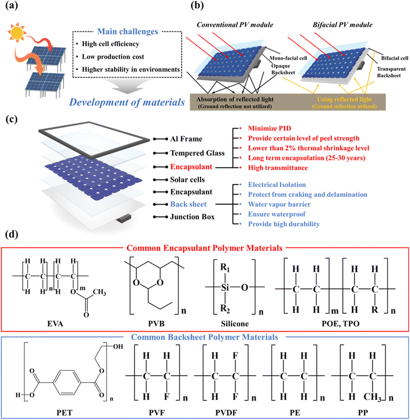
Over the last few decades, the use of fossil fuels has increased rapidly due to accelerating industrialization and the still-increasing world population.1 Because of the limited reserves of fossil fuels, oil and gas are expected to be depleted between the years 2052 and 2060.2 This means renewable energy resources are urgently needed to replace fossil fuels. Among the major renewable energy sources (wind, water, solar, and geothermal), solar energy is the most abundant renewable energy resource.3–7 As a result, solar power is increasingly regarded as a promising energy technology for the conversion of solar energy directly into electrical energy.8–10 Depending on the active material/architecture used, solar cells can be divided into Si solar cells, cadmium telluride solar cells (CdTe), organic solar cells, dye-sensitized solar cells (DSSC), gallium arsenide germanium (GaAs) solar cells, quantum solar cells, perovskite solar cells, and copper indium gallium selenide solar cells (CIGS).11–19 Si solar cells currently account for more than 90% of the entire solar market. All currently available PV modules degarde over time due to the external environment. Their performance is significantly reduced (Fig. 1a).20 To prevent this serious performance degradation, it is necessary to satisfy all requirements for cell efficiency, price, stability, module connectivity, and module configuration. In the past, researchers improved PV cell efficiencies with the help of different materials, introduced new designs (e.g., bifacial PV modules), and changed the module configuration.21–24 The currently emerging bifacial PV modules are also capable of using light that is reflected from the ground (Fig. 1b), while conventional PV modules only use sunlight that hits the top of the PV module. Conventional modules use an optically opaque backsheet for absorption, while bifacial PV modules use a transparent backsheet to let light pass through the rear of the PV module.25,26 The installation of bifacial solar panels, especially on highly reflective ground, can increase power production by 20–30%.27,28A PV module consists of multiple PV cells that are interconnected. Generally, PV cells consist of a frame, glass, encapsulant, solar cells, backsheet, and junction box.29,30Fig. 1c shows a more detailed structure of a PV module and the requirements that the encapsulant and backsheet should meet. The frame surrounding the edges of the module is made of aluminium, while carbon protects the module, and aids cooling by radiating heat away. The aluminium frame must protect the solar cells from external physical damage and have high transmittance for visible light. The encapsulant consists of a polymeric material to provide adhesion between the top surface, the rear surface, and the solar cells. The encapsulant should protect the relatively fragile solar cells and circuits from external forces, weather, corrosion, and UV light. Moreover, the encapsulant should maintain optical coupling between the solar cell and the incident sunlight and also minimize potential-induced degradation (PID). PID is caused by the potential between the module frame and the solar cell. This potential difference causes the sodium ions present in the glass to move, resulting in leakage current and output loss.31 And it must also achieve and maintain reliable electrical isolation of solar cell circuit elements.32 The encapsulant should also provide a certain peel strength (75–125 N cm−1) and gel content, little thermal shrinkage (<2%), and long-term stability (25–30 years). The backsheet ensures waterproofing, insulation, and durability of the solar module.33 In addition, because the backsheet is directly exposed to the environment, peeling, discoloration, and corrosion due to water vapor transmission can affect the output of the module – which means a water-vapor barrier is required.34,35 It must also serve to electrically isolate the internal circuitry from the environment. Durability is also important because the performance of a PV module rapidly deteriorates if cracking or delamination occurs. The junction box, which is located at the back, serves to protect the cables and circuit boards needed to deliver the electricity generated from the module to the inverter.
The encapsulant and backsheet are layers that protect the cell over a long period of time; the most commonly used encapsulant is ethylene vinyl acetate (EVA).36,37 EVA is regarded as the most suitable encapsulation material because it is inexpensive, relatively easy to handle, and it has been used for over 35 years.38 However, despite possessing these excellent properties, EVA undergoes photothermally induced polymer degradation.39 To overcome this problem, polymers such as ion-containing polymers (ionomers), polyvinyl butyl (PVB), polyethylene (PE), polyurethane (PU), silicone, and epoxy were studied. Polyolefin (PO), in particular, has been in the spotlight recently thanks to its high volume-resistance, low moisture-permeability, and lower PID.40 In particular, PO is increasingly used because of the increasing number of bifacial modules. Despite being 30% more expensive than EVA, PO is currently being explored as a new material with potentially sufficient long-term stability. The backsheet consists of a three-layer structure: an air-facing layer (with good weather resistance), a core layer (to ensure electric insulation), and a cell-facing layer (to ensure adhesion to the back encapsulant).41,42 Commonly employed processes for manufacturing three-layer backsheets include lamination, coating, or co-extrusion. The backsheet, which uses PET as a core layer, is laminated using an adhesive layer (epoxy or polyurethane) between layers.43 For the air-facing and cell-facing layers, either the fluoropolymer polyvinyl fluoride (PVF) or polyvinyl difluoride (PVDF) is typically used commercially. Their main purpose is to increase the UV resistance of the core layer, polyethylene terephthalate (PET).44 However, fluoropolymers have issues related to sustainability aspects, and they are expensive.45,46 Therefore, non-fluoropolymers are currently being investigated to overcome these problems. In addition, the industry has recently seen a surge in the popularity of the CPC structure due to the high cost of PVDF. This structure uses PET as the core layer and replaces the inner and outer films with a coating. Backsheets produced by co-extrusion without the use of adhesives are gaining attention as a viable alternative to the traditional lamination process, addressing the associated cost and quality concerns. As no adhesives are involved, the co-extruded backsheet can be converted to a monomeric state through a recycling process (pyrolysis) and then polymerised again. This co-extrusion approach uses a backsheet of PP for all three layers.41
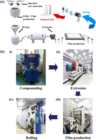
The above polymers are generally mixed with additives to increase the efficiency of PV modules and prevent polymer degradation.47,48 The encapsulant polymer and additives are compounded at a specific temperature and produced in the form of pellets or chips. They are then extruded into a film (Fig. 2). Depending on the material chosen and its intended use, the final film is produced through a series of steps including lamination, co-extrusion, calendering, casting, winding and stretching. The backsheet usually consists of a three-layer structure and the air and cell facing layers are either coated or laminated onto the core layer before being formed into a film. More recently, a co-extrusion process has gained ground, which eliminates the need for adhesives and allows precise thickness control.
2. Additives for encapsulants and backsheets
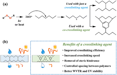
Because the efficiency of PV modules can be enhanced substantially with even a minute quantity of additives, the development of new polymers and additives is of great importance.49 Additives used in the encapsulant include agents that can accomplish the following tasks: facilitate crosslinking of polymers,50,51 control the density and speed of crosslinking,52,53 absorb UV light to prevent photodecomposition of polymers,54,55 act as antioxidants by neutralizing radicals generated by UV,56–58 and serve as silane-coupling agents that can increase the bonding strength for both solar cells and the encapsulant.59 All crosslinking agents have peroxide groups, while most co-crosslinking agents contain aryl groups (Table 1). When heat or UV light is applied to the peroxide, radicals are generated, and free radicals extract hydrogen from the polymer chain. Then, crosslinking occurs, where the free radicals and polymer chains combine (Fig. 3a). However, since it is difficult to achieve a high degree of crosslinking using a crosslinking agent alone, a co-crosslinking agent is frequently used at the same time. Co-crosslinking agents contain triaryl groups and affect the degree of crosslinking by minimizing steric limitations and optimizing the space between polymers. They can further improve both crosslinking density and crosslinking speed.60 Compared to using a crosslinking agent alone, using a co-crosslinking agent improves not only the crosslinking efficiency but also the moisture permeability as well as optical transmittance (Fig. 3b). Measurement of the degree of crosslinking of a polymer by a crosslinking agent is characterized through gel content analysis.61When the encapsulant absorbs UV light, polymer radicals form, and the polymer decomposes. Therefore, using an additive that destroys radicals following UV absorption is very desirable (Table 1). The benzotriazole and benzophenone groups with –OH absorb UV light effectively and can form hydrogen bonds with neighboring –CO or nitrogen. This generates a continuous resonance, and the absorbed UV energy is released as heat. After the resonance/absorption, the molecule returns to the original (stable) structure and continues to function as a UV absorber (Fig. 4a). UV absorbers operate at different absorption wavelengths. Therefore, a UV absorber that absorbs light in a certain wavelength range will not work for other wavelengths. Recently, two or more UV absorbers or antioxidants have been used together to cover a wider spectral range – from UV to near-visible light – see Fig. 4b.62
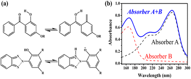 | ||
| Fig. 4 (a) Transition mechanism of benzophenone and benzotriazole under UV light. (b) Combined and individual UV absorption spectra of the two UV absorbers. | ||
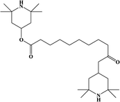
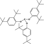
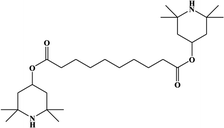
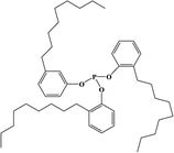
Antioxidants are used to neutralize radicals, which were generated by UV rays that were not blocked by UV absorbers. Phenolic antioxidants and hindered amine light stabilizers (HALS) are primary antioxidants that act as radical scavengers. Phenol-based antioxidants react with UV-generated polymer radicals and peroxy radicals to remove radicals (Fig. 5b). During this process, yellowing may occur due to the production of quinones.63 Amines in HALS react with peroxy radicals to oxidize and release alcohol, and the generated nitroxyl radicals serve as a catalyst and remove polymer radicals (Fig. 5a). Oxidation of HALS is a relatively slow and temperature-dependent process. Because it is also not very effective at high temperatures (above ∼80 °C), it is often used in combination with primary and secondary antioxidants. Unlike phenolic antioxidants, today, HALS are primarily used because a color change can be avoided (no quinone is produced). Secondary antioxidants usually protect and stabilize polymers by decomposing and removing peroxides that were generated in already-oxidized polymers. These are also known as peroxide “scavengers”. They reduce peroxide to prevent decomposition into PO− and OH− radicals. Phosphite is mainly used thanks to its excellent reducing ability (Fig. 5c). The influence of UV absorbers and antioxidants is analyzed by FT-IR analysis after UV weathering.63 The additives used in the solar panel backsheets are similar to the additives used in encapsulants. Several other additives are also commonly used: heat stabilizers (to improve heat dissipation by minimizing residual high-temperature heat), hydrolysis stabilizers (to prevent hydrolysis of polyesters, which is promoted by the terminal carboxylic acid), flame retardants (to prevent fire hazards), and inorganic pigments (to increase reflectance).64–66
 | ||
| Fig. 5 Removal mechanism of radicals using: (a) hindered amine 1st antioxidant, (b) phenolic 1st antioxidant, and (c) phosphite 2nd antioxidant. | ||
3. Encapsulant
To help improve PV modules, the encapsulant should have the following properties: good adhesion to both top- and bottom-layers, low light absorption, high thermal conductivity, physical strength (to protect cells from external impacts), good stability at high temperatures, good stability in UV light, optical transparency, and low thermal resistance.39 Polymers that are commonly used as encapsulants include EVA, PVB, silicone, thermoplastic olefin (TPO), and polyolefin elastomer (POE) – see Table 2.673.1. Ethylene vinyl acetate
In most PV modules, EVA is used as an encapsulant due to its high transmittance, low processing temperature, UV stability, high volume-resistivity, excellent adhesion, and elasticity. However, solar cell encapsulation with EVA films still has drawbacks. The disadvantages include high energy consumption during film fabrication, relatively short lifetimes, and polymer decomposition triggered by photothermal heat.32 Polymer decomposition following UV absorption can lead to Norrish reactions and the production of acetic acid (Fig. 6). The TGA analysis confirms that the vinyl acetate group present in EVA undergoes decomposition, resulting in weight loss as acetic acid molecules are released.68 If the produced acetic acid is not released through the backsheet (trapped in the PV module), it can cause metallization, which can reduce transmittance and yellowing, and lead to poor encapsulation overall.37,69 Many researchers have attempted to improve the durability of EVA films by introducing composites into EVA or using additives.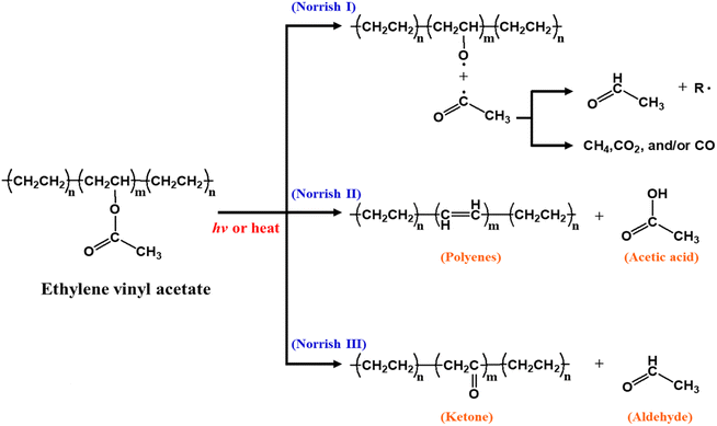 | ||
| Fig. 6 Schematic illustrating the EVA-degradation mechanism. Reproduced from ref. 39 with permission from Elsevier, copyright 2021. | ||
Oliveira et al. introduced graphene oxide (GO) to make EVA more resistant to photodegradation.70 Without the GO addition, the decomposition of the EVA encapsulant, which was treated with cyclohexane, was not slowed down. This can be concluded from the XRD results that indicate that the EVA encapsulant without GO dissolved in cyclohexane, and the crystallinity changed. The addition of GO increases crystallinity, which minimizes the diffusion of gaseous substances within the EVA encapsulant and helps suppress photooxidation. Photooxidation is a reaction where oxygen causes chain scission (breakage) of the polymer. The concentration of the added GO varied (0.25 wt% to 0.50 wt%, 0.75 wt%, 1.0 wt%, and 2.0 wt%). The GO addition reduced the deterioration of the EVA encapsulant significantly. However, when the concentration was high, the transparency of the film also decreased. Nanocomposites (GO/EVA) with a concentration of 0.25 wt% were still suitable for PV modules.
To improve the low thermal conductivity of the EVA layer, the lower EVA matrix layer was doped with three different nanoparticles: boron nitride (BN), zinc oxide (ZnO), and silicon carbide (SiC), at loading ratios of 10%, 20%, and 30%.71 This resulted in significant reductions in local and average solar cell temperatures for a 30% loading ratio – especially for SiC, which reduced the temperature of the solar cell device by approximately 2 K compared to BN and ZnO. Due to the low average cell temperature, the EVA nanoparticle layer also improved its thermal and electrical efficiencies. The thermal and electrical efficiencies for SiC reached maxima of 70.02% and 16.95%, respectively, and net electric power gain improved by 7.16%.
A method to improve the solar panel characteristics, by doping EVA with a small amount of nano ZnO nanoparticles (0.05 wt%, 0.1 wt%, 0.15 wt%), was reported previously.72 The EVA/ZnO composites showed superior electric insulation, fracture strain, good light transmission, and high tensile strength, from 3.7 MPa (for intrinsic EVA) to 15.3 MPa (for EVA/ZnO). At high temperatures, EVA/ZnO maintained a low dielectric constant and low heat dissipation. The 0.1 wt% EVA/ZnO nanocomposite showed the best performance and may be used as an alternative to the conventional EVA encapsulant in the future.
In one study, quantum dots (QDs) were mixed with EVA to produce a luminescent downshifting (LDS) layer, which can improve the (often) poor spectral response of solar cells to short-wavelength light. The LDS layer typically absorbs photons in the 300–500 nm range and emits them at longer wavelengths, where the PV device is much more efficient.73 A CuInS2/ZnS/ZnS core/shell/shell structure was embedded in EVA resin to fabricate QD@EVA films.74 The QD@EVA film was attached to a Si solar module to obtain I–V curves under simulated solar light (AM1.5G). As the QD concentration increased, light scattering from the aggregated QDs resulted in the emission of yellow light, and the incident-photon-to-electron conversion efficiency (IPCE) below 370 nm increased – see Fig. 7a and b. The conversion of near-ultraviolet light (below 370 nm) to visible light using QDs enhances the photocurrent of the solar module. Hase et al. investigated CuGaS2/ZnS core/shell QDs as wavelength-conversion materials for luminescent down-shifting (LDS) layers in solar cells.75 To control the bandgap (Eg) and emission wavelength, the Cu/Ga ratio was changed – see Fig. 7c. The optimal QDs (Eg ∼ 3.1 eV) were synthesized via hot injection at Cu/Ga = 1/10. The resulting QDs were embedded in EVA resin to fabricate the QDs@EVA film. Due to the excitation of the QDs, the QDs/EVA film not only absorbs UV light but also emits more-efficient warm white light when exposed to UV light. The relative change in ISC, when the QDs@EVA film was used instead of the blank EVA film, was −2.7%. However, the slightly reduced photocurrent for visible light (due to light scattering by aggregated QDs) is smaller than the improved response in the UV by the luminescent downshifting film. Furthermore, the light-scattering loss due to aggregation of QDs can be minimized by improving the affinity between the QDs and the resin.
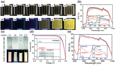 | ||
| Fig. 7 (a) Si solar module with a QD@EVA film under (i)–(vi) white light and (vii)–(xii) 365 nm UV light. (i) and (vii) As-purchased solar module. QD concentration: (ii) and (viii) 0, (iii) and (ix) 0.2, (iv) and (x) 0.63, (v) and (xi) 3.2, (vi) and (xii) 6.2 wt%. (b) IPCE spectra of the single Si solar module (i)–(v) covered with QD@EVA films (vi) without a film. The insets show magnified spectra in the near-UV and visible regions. QD concentration: (i) 0, (ii) 0.2, (iii) 0.63, (iv) 3.2, (v) 6.2 wt%. (c) Photographs of CGS/ZNs QD dispersions in toluene, under white light and UV (365 nm) light. (d) I–V curves and (e) IPCE spectra of a Si solar module with an EVA film and a QDs@EVA film. Reproduced from ref. 74 with permission from the American Chemical Society, copyright 2020. Reproduced from ref. 75 with permission from the Royal Society of Chemistry, copyright 2013. | ||
3.2. Polyvinyl butyral
Polyvinyl butyral (PVB) is a thermoplastic polymer with a cost similar to EVA. It is the second most commonly used encapsulant material on the market. PVB features better UV stability and adhesion than EVA,76 and it has a high recovery rate with a recycled purity of 98%.77 In addition, PVB is also widely used for thin-film building integrated photovoltaic (BIPV) products.78,79 Unfortunately, it is very vulnerable to hydrolysis because of its high water absorption,80 and it has inferior volume resistance.The PVB encapsulant shows lower potential-induced degradation (PID) when paired with a specific superstrate. PV modules with the soda-lime/EVA structure showed high loss (32%) according to PID testing, while PV modules with the quartz/PVB configuration showed only 1% degradation – see Fig. 8a.81 Furthermore, uniformly dispersed iron-doped titania nanoparticles (Fe–TiO2) in PVB film produced improved UV stability – see Fig. 8b.82 The UV exposure of the produced film increases the hydrophilicity of Fe–TiO2 nanoparticles, which increases cohesion between nanoparticles. The agglomerated particles are repelled by the illuminated surface due to both the interfacial enthalpy effect and the depletion force (caused by the polymer structure entropy). As a result, the particles produce an Fe–TiO2-enriched layer on the surface. The formed composite film had a very low carbonyl index and high tensile-strength retention in UV-aging tests. Overall, it exhibited superior UV stability compared to other photo-stabilizers. It was also shown that the ultra-thin nanoparticle layer can suppress UV degradation and extend the service life of the PVB film. Moulai et al. studied the optical properties of the PVB encapsulant with QDs. Luminescent QDs (LQDs) emerged with PVB and were used as an encapsulant for luminescent down-shifting.83 The use of LQDs with PVB resulted in increased PVB absorption and increased luminescent emission in both the UV and visible wavelength ranges. LDS, through the introduction of LQDs, allows PV modules to increase their output by improving the response in the UV spectrum.
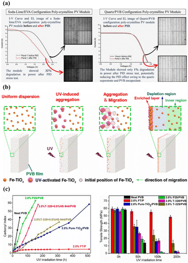 | ||
| Fig. 8 (a) Electroluminescence (EL) images and I–V curves of a module before and after PID. (b) Mechanism of Fe–TiO2 nanoparticles in PVB film, (c) UV stability and tensile strength of PVB films with Fe–TiO2 nanoparticles. Reproduced from ref. 81 with permission from Elsevier, copyright 2022. Reproduced from ref. 82 with permission from Elsevier, copyright 2022. | ||
3.3. Silicone
The silicone encapsulant is based on –Si–O– or similar backbone structures rather than hydrocarbon structures. Polydimethylsiloxane (PDMS) and its derivatives have been used to laminate solar cells in solar modules since the early 1980s due to their excellent stability and durability in many types of environments.84 Silicone encapsulants show less performance degradation of PV modules than EVA.85 However, they are much more expensive and complicated to use in PV modules, which means their use in the PV market is limited.86 Despite these barriers, silicones can improve PV module efficiency due to their UV resistance, lack of discolouration, PID suppression and excellent light transmission.86–89 They are already used in highly specialized applications despite their high price and very specific processing requirements, and they were shown to improve the power output of PV modules by 2–3% on average in desert-like environments.90 Recently, a silicone encapsulant, which can be processed using conventional vacuum-thermal lamination, was reported.91 Similar characteristics to conventional (liquid) silicone were found in a study that focused on the reliability of PV modules where silicone was used as an encapsulant. Unlike PV modules equipped with EVA, no corrosion was observed in EL images following exposure to damp heat for 6000 hours – see Fig. 9a and b. Interestingly, neither corrosion nor PID was reliably detected even when the silicone encapsulant was used only at the front surface. Details of other properties (including stability and durability as thermomechanical/optical weathering stress factors) were not reported but similar reliability to PV modules using conventional silicone is expected. Therefore, it is estimated that the use of silicone materials will likely increase after additional testing and verification. In addition, thermoplastic silicone elastomers, silicones combined with thermoplastics, can cure encapsulation materials faster and facilitate additive-free physical crosslinking.92 Liu et al. investigated the gamma irradiation stability of silicone encapsulant materials – see Fig. 9c.93 The group found that the overall mechanical properties transformed from rubber-like to brittle after increasing the absorbed dose to 500 kGy (thanks to the increased crosslinking-density of the silicone encapsulant). The dose-rate effect of silicone encapsulants was further confirmed by characterizing radiolysis gases at very low dose-rates (10−4 Gy s−1). These findings provide guidance for the application of silicone encapsulants in high-radiation environments.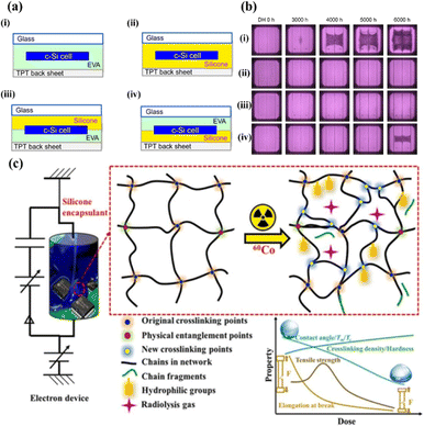 | ||
| Fig. 9 (a) Schematic structures of Si PV modules [(i): glass/EVA/Si-cell/EVA/TPT, (ii): glass/silicone/Si-cell/silicone/TPT, (iii): glass/silicone/Si-cell/EVA/TPT, (iv): glass/EVA/Si-cell/silicone/TPT]. (b) EL images of Si PV modules based on EVA and silicone encapsulants (modules A, B, C, and D) before and after the damp heat test. (85 °C with 85% relative humidity.) (c) Irradiation-induced degradation of the silicone encapsulant. Reproduced from ref. 91 with permission from IOP science, copyright 2018. Reproduced from ref. 93 with permission from Elsevier, copyright 2022. | ||
3.4. Polyolefin
Polyolefin (PO) encapsulation is currently studied as an alternative to EVA. POs, when used in photovoltaic modules, have a similar composition to EVA. They are PE-based chemicals without vinyl-acetate side groups and have the advantage of being very inexpensive. Both POE and TPO are PO-based materials with the benefit that they do not generate acetic acid because they do not contain vinyl acetate moieties.94 Because studies of PO have been conducted only recently, there are no finished long-term studies yet.TPO is a polymer blend that consists of an olefinic elastomer and a thermoplastic polyolefin. It has a similar or higher volume resistivity and a lower WVTR than EVA. In addition, it has a higher melting temperature, which eliminates the need for a crosslinking process. Without the crosslinking process, all chemicals and crosslinking-reaction-related by-products can be avoided. In addition, the curing time needed to crosslink the encapsulants can be eliminated, which reduces the lamination cycle time significantly.95 TPO showed higher transmittance and higher thermal stability than EVA, is less sensitive to creep, and has excellent adhesion to the glass/encapsulant interface as well as at the glass/backsheet interface – see Fig. 10.96
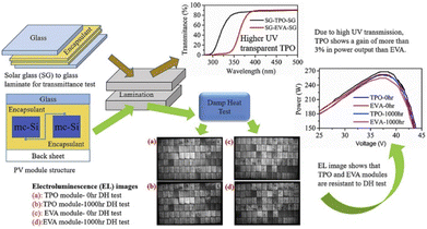 | ||
| Fig. 10 Results of the damp heat (DH) test and power voltage test of PV modules with EVA and TPO encapsulants. Reproduced from ref. 96 with permission from Elsevier, copyright 2020. | ||
In the damp-heat weather-simulation test, the results show high transmittance and little yellowing even after a longer period – see Fig. 11a and b.97,98 Ottersböck et al. studied the effect of microclimates on encapsulant degradation.99 Under UV irradiation, there is evidence of a deacetylation reaction, which can be identified by an increase in the crystallization temperature. This was found in the samples that were laminated using EVA, while only morphological changes (which are related to a reversible process) were detected for TPO. Even though POE also requires a crosslinking step like EVA, the acid formation does not occur because it does not have a vinyl group. In addition, it has a lower PID than EVA due to its high-volume resistance and low moisture permeability – see Fig. 11c.100 However, POE has the disadvantage of a slow cross-linking reaction. This problem has been addressed by the introduction of functional vinyl groups.40 The vinyl group of PO reacts easily with the curing agent, which increases the crosslinking rate 14 times, and it increases the maximum G′ value (which represents the melt strength) to 69.0 kPa. Moreover, the introduction of the vinyl group reduces the amount of curing agent, which eliminates the need for curing coagents. It is also very transparent, with excellent volume resistivity, and a low water-vapor transmission rate. French et al. studied modules with different back encapsulants exposed to high temperature and high humidity conditions (85 °C and 85% RH).101 As a result, using the POE encapsulant, the output power of polycrystalline single-sided Al-BSF cells, monocrystalline bifacial passivated emitter and rear cells (PERCs), and polycrystalline bifacial PERCs, showed significantly reduced power loss. Oreski et al. studied the difference between EVA and TPO or POE modules after 3000 hours of DH testing. The group found that EVA showed signs of silver grid corrosion, but not TPO and POE.102 Therefore, it appears that PO-based encapsulants can potentially replace EVA. For bifacial PV modules, in particular, because of their high cell efficiency, it is very important to prevent PID caused by the movement of metal ions. The PO-based encapsulant can potentially prevent PID better than commercially available EVA because it inhibits the movement of ions. The PO-based encapsulant is a material that is currently attracting significant attention and is expected to capture a larger share of the solar energy market in the future.
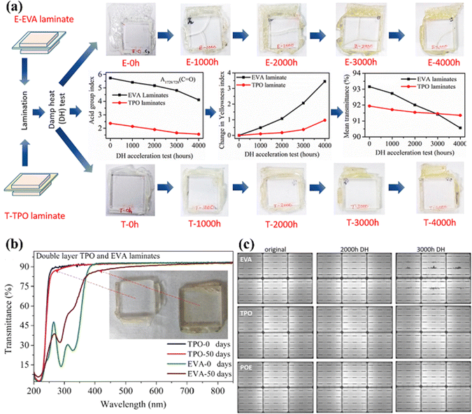 | ||
| Fig. 11 (a) Comparison of film photographs, acid group index, change in yellowness index, and mean transmittance of EVA and TPO encapsulants. (b) The transmittance of double-layer laminates before and after 50 days of UV exposure. (c) EL images of test modules with EVA, TPO, and POE encapsulants before and after 2000 and 3000 hours of DH testing (85 °C with 85% RH). Reproduced from ref. 98 with permission from Elsevier, copyright 2021. Reproduced from ref. 97 with permission from Elsevier, copyright 2019. Reproduced from ref. 102 with permission from Wiley, copyright 2020. | ||
4. Backsheet
The backsheet is used to protect the back of the PV module. The materials that make up the backsheet must protect the PV modules from UV radiation, moisture and vapour ingress. It is also necessary to ensure complete electrical insulation of the PV panel. This is done to ensure the continued performance of the module. As a backsheet material, PET is widely used because it is inexpensive. However, PET (a polyester) is hydrolyzed due to the hydrolyzable ester bonds in the backbone. Unfortunately, the hydrolysis of PET causes chain scission (polymer degradation) which worsens the mechanical properties, increases embrittlement, and reduces UV resistance.103–105 To prevent hydrolysis, PET is sometimes enhanced with anti-hydrolysis additives (e.g., carbodiimide-based compounds or esters of phosphoric acid). Unfortunately, this process is complicated, and the production cost is high.106–108 To overcome this problem, PET is often sandwiched between two UV-resistant films through a lamination process.109 The most common type of backsheet is an opaque multi-layer polymer sheet on the back of a module. The multi-layer structure consists of a weather-resistant air-facing layer, a core layer for electrical insulation, and a cell-facing layer that maintains adhesion to cells (Fig. 12). The most common structures are Tedlar–PET–Tedlar (TPT) or Kynar–PET–Kynar (KPK). The thicker the core layer, the better the insulation and mechanical strength; and the thinner the inner and outer layers, the better both the adhesion and resistance.110 The predominantly used fluoropolymer works very well but is expensive. In addition, recycling fluoropolymers is not possible because toxic by-products (e.g., carbonyl fluoride, trifluoroacetic acid, hydrogen fluoride) form during the combustion process.111 To overcome these drawbacks, new backsheets, which are based on non-fluoropolymer outer layers, are currently being developed. Some of these new backsheet materials are based on polyamide (PA), PE, or polypropylene (PP) – see Fig. 12. Since these materials are more susceptible to environmental degradation than fluoropolymers, a suitable modification is required. Nevertheless, they are generally cheaper and make it easier to recycle modules, which aligns well with the ultimate goal of sustainability in PV technology.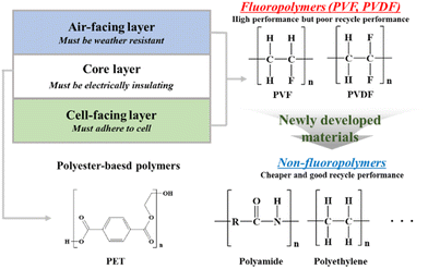 | ||
| Fig. 12 Schematic illustrating the benefits and required function of multi-layer backsheets and the chemical structure of polymers used to make them. | ||
4.1. Fluoropolymers
A PVF containing backsheet was developed in the 1980s and has been commonly used as a first-generation backsheet. It is still widely used today thanks to its excellent weatherability, stability, and proven good performance in many outdoor applications.112 Backsheets made of PVF and PET have been used for over 30 years. Thus, they can serve as useful standards for both performance and durability. Compared to other backsheet materials, the long-term performance was also good.113,114 Recently, polyvinylidene fluoride (PVDF) or non-fluoropolymers rather than PVF have started to attract the attention of researchers due to potential advantages in both price and composite formation.PVDF has been used as a backsheet material since 2003.115 To reduce the cost of the PVDF-based backsheet and improve the adhesive properties, poly(methyl methacrylate) (PMMA), which has excellent insulation, chemical resistance, and stiffness, and is highly miscible with PVDF, was mixed with pigments and additives. Ulicna et al. investigated the deterioration of PVDF-A, where the PVDF–PMMA layer was exposed to the outside, and PVDF-B, a layered structure without PMMA exposed on the surface.110 The FTIR spectrum of monolayer PVDF-A showed a very low PMMA peak after combined-accelerated stress testing (C-AST). The test was performed using NREL's and DuPont's module accelerated stress test (MAST) where the effects of DH, UV, and temperature cycle (TC) were tested sequentially. This means that PMMA disappeared/transformed at the exposed surface of the backsheet. On the other hand, no decrease of the PMMA peak was observed for any of the single-stress test conditions where DH, UV, and TC were applied individually. For PVDF-B, a PMMA peak could not be detected using FTIR due to its thickness, but it was confirmed that it exhibits a similar pattern to PVDF-A based on differential scanning calorimetry (DSC) and wide-angle X-ray scattering (WAXS) results.
In addition to PMMA, researchers are now focusing on fabricating backsheets made from PVDF composites. Mohammed Khalifa et al. reported PVDF/nano-mica nanocomposite films – see Fig. 13a.116 In these films, the thermal conductivity and tensile strength of PVDF increased depending on the amount of nano-mica added (Fig. 13b and c). In addition, the strong interaction between nano-mica and PVDF chains increases wettability and the dielectric constant, and the film gradually becomes opaque with increasing amounts of nano-mica. Moreover, as nano-mica loading increases, the coefficient of thermal expansion (CTE) decreases. Because the surface of PVDF is rough and uneven, the addition of nano-mica increases the hydrophobicity of PVDF and the thermal conductivity by creating a heat-flow path. At optimal loading (PVDF-M2.0), the PVDF film showed a transmittance of 70%. In addition, it showed excellent stability when exposed to UV.
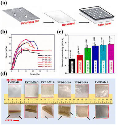 | ||
| Fig. 13 (a) Schematic representation of PVDF/nano-mica nanocomposite films in a solar panel backsheet. (b) Stress–strain curves, (c) thermal conductivity, and (d) thermal shrinkage (150 °C, 12 hours) of PVDF/nano-mica films for different quantities of nano-mica loading. Reproduced from ref. 116 with permission from Elsevier, copyright 2022. | ||
PVDF features high purity, chemical inertness, mechanical abrasion resistance, UV stability, and excellent thermal stability of the polymer due to the high electronegativity and dissociation energy of the C–F bonds.110 Although it is generally resistant to moisture and does not decompose at high temperatures, PVDF has a relatively low thermal conductivity which cannot sufficiently dissipate the heat generated in the panel. Therefore, Kim et al. used different ratios of AlN and BN fillers to fabricate PVDF backsheets for solar cells that have high thermal conductivities. The group found that composites with 70 wt% and a 2![[thin space (1/6-em)]](https://www.rsc.org/images/entities/char_2009.gif) :
:![[thin space (1/6-em)]](https://www.rsc.org/images/entities/char_2009.gif) 8 AlN/BN ratio showed a maximum thermal conductivity of 5.85 W m−1 K−1, which is 31 times larger than that of the pure PVDF matrix. The storage modulus was comparable to that of polyethylene terephthalate (PET), which is normally used to make PVDF harder. The water swelling ratio was reduced by adding a filler, and the thermal and mechanical properties after swelling and drying did not worsen. In addition, a surface modification of the filler was performed (with a silane-coupling agent) to improve the interfacial adhesion between the filler and the matrix. To overcome the problem associated with multi-layered backsheets, a PVDF single-layer structure was used. The inherent hardness of a ceramic filler provided PVDF with rigidity, which meant that the device could maintain its shape (even outdoors) without requiring a PET layer.117
8 AlN/BN ratio showed a maximum thermal conductivity of 5.85 W m−1 K−1, which is 31 times larger than that of the pure PVDF matrix. The storage modulus was comparable to that of polyethylene terephthalate (PET), which is normally used to make PVDF harder. The water swelling ratio was reduced by adding a filler, and the thermal and mechanical properties after swelling and drying did not worsen. In addition, a surface modification of the filler was performed (with a silane-coupling agent) to improve the interfacial adhesion between the filler and the matrix. To overcome the problem associated with multi-layered backsheets, a PVDF single-layer structure was used. The inherent hardness of a ceramic filler provided PVDF with rigidity, which meant that the device could maintain its shape (even outdoors) without requiring a PET layer.117
In addition, polyhedral oligomeric silsesquioxane (POSS)-functionalized carbon nanotubes (CNTs) were used as fillers to improve the low thermal conductivity of PVDF. Many researchers have used CNTs to increase low thermal conductivity.118–120 However, the thermal conductivity of these composites did not increase much because the CNTs aggregated. Song et al. performed surface modification of CNTs to increase the dispersibility of CNTs in the solvent DMF and increase the compatibility with the PVDF matrix.121 The surface modification of CNTs was carried out in two steps: (1) functionalization with –COOH, (2) functionalization with –POSS (Fig. 14a). Through these surface modifications, uniform dispersion of CNT–POSS nanoparticles in the PVDF matrix and high crystallinity of PVDF became possible – see Fig. 14b. In addition, both thermal stability and the mechanical properties were improved substantially by the POSS nanoparticles. The fabricated CNT–POSS/PVDF composite film showed a very high thermal conductivity of 1.12 W m−1 K−1 (0.15 W m−1 K−1 in the case of pure PVDF) – see Fig. 14c. The nucleation effect due to increased crystallinity of the CNT composite appeared to affect the thermal properties positively.
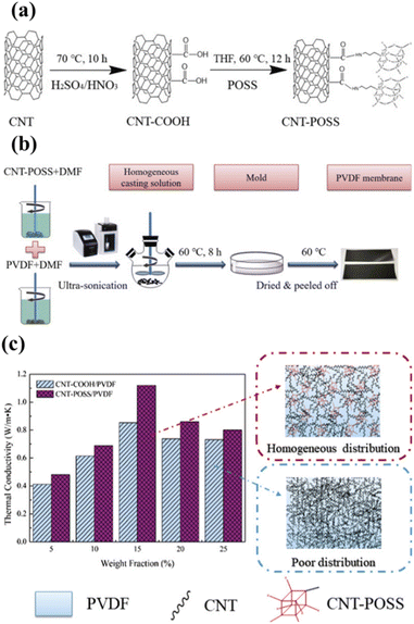 | ||
| Fig. 14 (a) Schematic illustrating the preparation of CNT–POSS. (b) Schematic of the preparation of the CNT–POSS/PVDF composite membrane. (c) Thermal conductivity of CNT–COOH/PVDF and CNT–POSS/PVDF composite membranes with different filler loadings. Reproduced from ref. 121 with permission from Elsevier, copyright 2018. | ||
4.2. Non-fluoropolymers
Polyamide (PA) was used as the original coextrusion backsheet.122 However, recent studies have shown that it shrinks and cracks after installation.123,124 Specifically, the cracking of PA was promoted by the acetic acid from the EVA encapsulant.125 Backsheet materials in general are subjected to accelerated laboratory testing based on individual set conditions prior to market introduction. However, PV modules are subject to more complex degradation mechanisms due to a wide range of environmental stressors that vary around the world. To avoid these complications and to more reliably test the long-term reliability of new PV modules, it is necessary to combine (and standardise) accelerated laboratory tests with both key environmental factors and typical mechanical loads.126The PO-based backsheets showed higher durability compared to the currently used PET-based backsheets, and they can extend the service life of PV modules significantly. Moreover, POs can also be made more environmentally robust without an outer fluoropolymer layer. Thuis et al. compared and investigated the industrial applicability of non-fluoropolymer backsheets.127 Unlike other materials, the PO-based backsheet was not prone to surface cracks that promote bulk damage, and they are very tough – even after the aging test (85 °C, 85% RH, 4000 hours).
Omazic et al. investigated the weathering effects on the stability of modified polyolefin (MPO) backsheets as an alternative to PET/fluoropolymer backsheets.128Fig. 15 shows that the MPO backsheet has a lower WVTR and higher acetic acid transmission rate (AATR) compared to PET. In other words, the PV modules have less water permeation and lower acetic acid content. Artificial aging of PET under DH and irradiation conditions led to chain scission and chemo-crystallization, which increases embrittlement and reduces strain at break by 70%. On the other hand, the MPO backsheet maintained mechanical flexibility even after aging for 2000 h with only a slight decrease in fracture strain (by up to 20%) and a slight increase in yield stress. For the applied accelerated-aging test conditions, it was confirmed that the weather resistance of the MPO backsheet was higher than for PET. This indicates that the MPO backsheet can replace the PET-based backsheet in terms of cracking and delamination reduction. Several studies have already reported excellent stability at high temperatures and high humidity, as well as for a wide range of light exposure scenarios.129,130
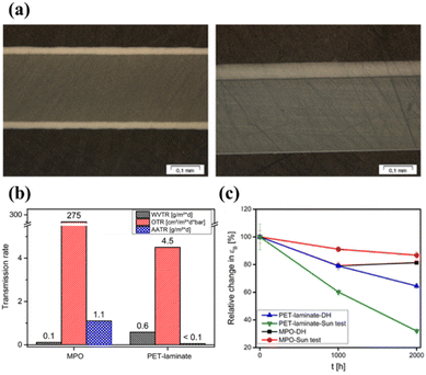 | ||
| Fig. 15 (a) Cross-section images of PET (left) and MPO (right). (b) Permeation rates for the PET and MPO backsheets. (c) Change of fracture strain for the PET and MPO backsheets before and after aging. Reproduced from ref. 128 with permission from Elsevier, copyright 2020. | ||
The effect of the special properties of PP backsheets on the performance and reliability of PV modules was investigated in ref. 41. Compared to PET-based backsheets (PPF), the output was 1.5–2.5% higher. This difference was caused by the higher reflectivity of the PP-based backsheet (80% for PP vs. 68% for PPF). In addition, the PP backsheet showed little change in power output after 3000 hours of DH testing. The module with the EVA encapsulant and the PPF backsheet showed silver grid corrosion after 3000 hours of DH testing, which was due to acetic acid. However, the module with the EVA encapsulant and the PP backsheet showed certain penetration characteristics (humidity prevented from entering the module, acetic acid diffusing out of the PV module). Despite these benefits, long-term true outdoor aging tests are needed to obtain reliable long-term aging data because research on PO-based backsheets has only been conducted recently.
Another recent development for backsheets is to make them transparent. In the past, transparent backsheets have been used in BIPVs to blend with the color of the background roof or glass. Recently, however, a transparent backsheet was developed for bifacial PV modules to increase module efficiency. Currently, 90% of bifacial modules are made of GG (glass-to-glass) structures.131 Lately, however, GB (glass-to-backsheet) structures have been developed because there are benefits in terms of lightness, cost reduction, ease of transportation, and installation. It was also confirmed that GB structures had lower PIDs than GG structures.132 The transparent backsheet also needs to block UV light while transmitting visible light reflected from the ground. UV exposure can be reduced by using a white grid pattern on the inside of the backsheet to block and reflect the correct light between the cell gaps.133 Arihara et al. compared the reliability and long-term durability of GB and GG modules using a DH test.134 There were three comparison groups: GG modules with EVA encapsulants, and GB modules using EVA and PO encapsulants (Fig. 16a). Fig. 16b and c show the changes in output power (Pmax) and EL images before and after the DH test. The GG module showed no degradation up to 3000 hours of DH, but Pmax decreased to 0.88–0.89 after 4000 hours of DH. This degradation was further accelerated after 5000 hours of DH. The EL image shows that a dark area appears at the edge of the module. For the GB module with the EVA encapsulant, Pmax decreased to 0.25 after 5000 hours of DH. This was confirmed by the obtained EL image. In both modules, this phenomenon was found to occur due to increasing series resistance (Rs) caused by the hydrolysis reaction of EVA and generation of acetic acid gas (and a corresponding decrease in fill factor (FF)). On the other hand, in the modules with PO and GB, almost no decrease in Pmax was observed even after 5000 hours. Moreover, defects such as cracks and voids did not appear in the EL image. It appears that not only a transparent backsheet but also a PO encapsulant are essential for bifacial PV modules.
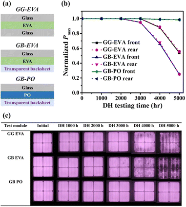 | ||
| Fig. 16 (a) Schematic cross-section, (b) normalized Pmax retention, and (c) EL images of PV modules with different configurations (GG EVA, GB EVA, GB PO). Reproduced from ref. 134 with permission from IOP science, copyright 2018. | ||
5. Discussion and outlook
PV modules use various polymer layers to protect the cells, but their performance tends to degrade under the influence of high temperatures, UV radiation and moisture conditions during field operation. The careful design of the initial polymer layer and the accurate selection of materials are of paramount importance, especially as PV modules are maintained in their initial conditions for decades. The choice of polymer plays a key role in influencing the properties of the encapsulant and backsheet. Continuous efforts have been made in polymer development to improve various aspects of PV modules, including price, long-term stability and overall performance. Recognising that the exclusive use of single polymers may have limitations in improving performance, several researchers are exploring compounding with polymers to enhance the properties of encapsulants and backsheets. In this context, various material solutions for encapsulants and backsheets are discussed below:(1) Polymers of the encapsulant:
- The main functions of encapsulants include protecting cells from solar corrosion, ensuring high thermal conductivity and optical transparency.
- EVA is widely used due to its affordability and ease of handling, but it is subject to polymer degradation, resulting in the formation of acetic acid.
- In order to improve PV module performance and address PID (Potential-Induced Degradation), alternative polymers such as PVB, silicone, PO, etc. have been developed.
- PO, in particular, shows potential for improving module performance and suppressing PID, making it a current focus of encapsulant studies.
(2) Polymer of the backsheet:
- Backsheets play a critical role in providing waterproofing, insulation and durability for PV modules.
- PET is commonly used as a core layer sandwiched between protective layers to improve UV stability.
- Fluoropolymers PVF and PVDF serve as outer layers, but due to cost concerns, non-fluoropolymer based backsheets are being actively investigated.
- Recently, PO-based backsheets have been attracting attention, not only because of their price, but also because of their applicability in co-extrusion and the use of transparent backsheets.
(3) Alternative backsheet manufacturing method to substitute lamination:
- The traditional lamination process for PET-based core layer backsheets uses adhesives, which has an impact on cost and time.
- Coatings are emerging as an alternative to expensive PVDF and are dominating the market due to their cost effectiveness.
- Co-extrusion eliminates adhesives, allows thickness optimisation, reduces costs and avoids processes that lead to material degradation. It also has the potential to replace expensive fluoropolymers with more economical polymers such as PE and PP.
(4) Additives and compounds for the backsheet and encapsulant:
- Backsheet and encapsulant additives and compounds include a variety of materials designed to improve specific properties or functionalities.
- These additives and compounds play a critical role in improving the overall performance of photovoltaic module backsheets and encapsulants, such as adhesion, crosslinking and UV resistance.
- Key additives include crosslinkers, co-crosslinkers, UV absorbers, antioxidants, silane coupling agents, heat stabilisers, hydrolysis stabilisers and flame retardants.
- Several compounds (e.g. CNTs, graphene, TiO2, AlN, BN, ZnO, etc.) are often used in combination with polymers to improve key properties.
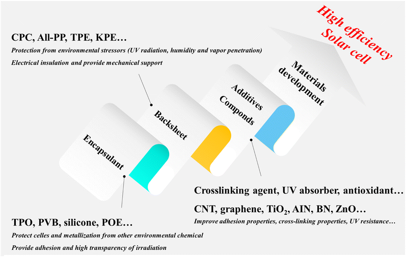
In summary, the change from currently used EVA, PET and fluoropolymers to low cost polymers such as PE and PP, along with additives and compounds, is very important in terms of materials and is an important part of improving PV modules (Fig. 17). We believe this review provides a comprehensive overview of the current state of the art in PV module materials. It provides insight into the common materials that are widely used to meet the functional requirements of encapsulants and backsheets, while also providing guidance for the development of new materials for these critical components.
Author contributions
Donggyun Kim: conceptualisation, searching the literature, writing – original draft; Hyunsoo Lim: conceptualisation, searching the literature, writing – review & editing; Sung Hyun Kim: conceptualisation, searching the literature; Kang No Lee: conceptualisation, review & editing; Jungmok You and Du Yeol Ryu: conceptualisation, searching the literature, writing – review & editing; Jeonghun Kim: supervision, validation, funding acquisition, project management, writing – review & editing.Conflicts of interest
The authors declare that they have no known competing financial interests or personal relationships that could have appeared to influence the work reported in this paper.Acknowledgements
This work was supported by the New & Renewable Energy of the Korea Institute of Energy Technology Evaluation and Planning (KETEP) and the Ministry of Trade, Industry & Energy (MOTIE) of the Republic of Korea (No. 20213030010430 and 20213030010240) and NRF grant (2022R1A4A1020543) funded by the Ministry of Science, ICT & Future Planning (MSIP), Korea.References
- N. Abas, A. Kalair and N. Khan, Futures, 2015, 69, 31–49 CrossRef.
- A. Kalair, N. Abas, M. S. Saleem, A. R. Kalair and N. Khan, Energy Storage, 2021, 3, e135 CrossRef.
- D. J. Davidson, Nat. Energy, 2019, 4, 254–256 CrossRef.
- J. Mohtasham, Energy Procedia, 2015, 74, 1289–1297 CrossRef.
- M. Soltani, F. M. Kashkooli, M. Souri, B. Rafiei, M. Jabarifar, K. Gharali and J. S. Nathwani, Renewable Sustainable Energy Rev., 2021, 140, 110750 CrossRef.
- F. Bilgili, D. B. Lorente, S. Kuşkaya, F. Ünlü, P. Gençoğlu and P. Rosha, Renewable Energy, 2021, 178, 283–294 CrossRef CAS.
- Q. Wen, X. He, Z. Lu, R. Streiter and T. Otto, Nano Mater. Sci., 2021, 3, 170–185 CrossRef.
- T. Shiyani and T. Bagchi, Nanomater. Energy, 2020, 9, 39–46 CrossRef.
- V. Sharma and S. Chandel, Renewable Sustainable Energy Rev., 2013, 27, 753–767 CrossRef.
- M. Bertolli, Course: Solid State II, Department of Physics, University of Tennessee, Knoxville, 2008 Search PubMed.
- T. Saga, NPG Asia Mater., 2010, 2, 96–102 CrossRef.
- R. Xue, J. Zhang, Y. Li and Y. Li, Small, 2018, 14, 1801793 CrossRef PubMed.
- R. Wang, M. Mujahid, Y. Duan, Z. K. Wang, J. Xue and Y. Yang, Adv. Funct. Mater., 2019, 29, 1808843 CrossRef CAS.
- A. Alizadeh, M. Roudgar-Amoli, S.-M. Bonyad-Shekalgourabi, Z. Shariatinia, M. Mahmoudi and F. Saadat, Renewable Sustainable Energy Rev., 2022, 157, 112047 CrossRef CAS.
- V. Fthenakis, C. Athias, A. Blumenthal, A. Kulur, J. Magliozzo and D. Ng, Renewable Sustainable Energy Rev., 2020, 123, 109776 CrossRef CAS.
- R. K. Raman, S. A. G. Thangavelu, S. Venkataraj and A. Krishnamoorthy, Renewable Sustainable Energy Rev., 2021, 151, 111608 CrossRef CAS.
- M. Stuckelberger, R. Biron, N. Wyrsch, F.-J. Haug and C. Ballif, Renewable Sustainable Energy Rev., 2017, 76, 1497–1523 CrossRef.
- W. Liu, H. Ma and A. Walsh, Renewable Sustainable Energy Rev., 2019, 116, 109436 CrossRef CAS.
- N. Mufti, T. Amrillah, A. Taufiq, M. Diantoro and H. Nur, Sol. Energy, 2020, 207, 1146–1157 CrossRef CAS.
- P. Rajput, G. Tiwari, O. Sastry, B. Bora and V. Sharma, Sol. Energy, 2016, 135, 786–795 CrossRef.
- M. Sharma, S. Pareek and K. Singh, IOP Conf. Ser.: Mater. Sci. Eng., 2019, 594, 012031 CrossRef.
- Y. Liu, Y. Li, Y. Wu, G. Yang, L. Mazzarella, P. Procel-Moya, A. C. Tamboli, K. Weber, M. Boccard and O. Isabella, Mater. Sci. Eng., R, 2020, 142, 100579 CrossRef.
- S. Jouttijärvi, G. Lobaccaro, A. Kamppinen and K. Miettunen, Renewable Sustainable Energy Rev., 2022, 161, 112354 CrossRef.
- I. Mehedi, Z. Salam, M. Ramli, V. Chin, H. Bassi, M. Rawa and M. Abdullah, Renewable Sustainable Energy Rev., 2021, 146, 111138 CrossRef.
- R. Guerrero-Lemus, R. Vega, T. Kim, A. Kimm and L. Shephard, Renewable Sustainable Energy Rev., 2016, 60, 1533–1549 CrossRef CAS.
- B. Marion, S. MacAlpine, C. Deline, A. Asgharzadeh, F. Toor, D. Riley, J. Stein and C. Hansen, presented in part at the 2017 IEEE 44th Photovoltaic Specialist Conference (PVSC), 2017 Search PubMed.
- X. Sun, M. R. Khan, C. Deline and M. A. Alam, Appl. Energy, 2018, 212, 1601–1610 CrossRef.
- T. Dullweber and J. Schmidt, IEEE Journal of Photovoltaics, 2016, 6, 1366–1381 Search PubMed.
- Z. Wu, Y. Hu, J. X. Wen, F. Zhou and X. Ye, IEEE Access, 2020, 8, 132466–132480 Search PubMed.
- E. J. Schneller, R. P. Brooker, N. S. Shiradkar, M. P. Rodgers, N. G. Dhere, K. O. Davis, H. P. Seigneur, N. Mohajeri, J. Wohlgemuth and G. Scardera, Renewable Sustainable Energy Rev., 2016, 59, 992–1016 CrossRef CAS.
- M. Aghaei, A. Fairbrother, A. Gok, S. Ahmad, S. Kazim, K. Lobato, G. Oreski, A. Reinders, J. Schmitz and M. Theelen, Renewable Sustainable Energy Rev., 2022, 159, 112160 CrossRef CAS.
- A. Czanderna and F. Pern, Sol. Energy Mater. Sol. Cells, 1996, 43, 101–181 CrossRef CAS.
- Y. Zhang, J. Xu, J. Mao, J. Tao, H. Shen, Y. Chen, Z. Feng, P. J. Verlinden, P. Yang and J. Chu, RSC Adv., 2015, 5, 65768–65774 RSC.
- B. Bora, O. Sastry, R. Kumar, R. Dubey, S. Chattopadhyay, J. Vasi, S. Mondal and B. Prasad, IEEE Journal of Photovoltaics, 2020, 11, 453–460 Search PubMed.
- M. Alaaeddin, S. Sapuan, M. Zuhri, E. Zainudin and F. M. Al-Oqla, Renewable Sustainable Energy Rev., 2019, 102, 318–332 CrossRef CAS.
- A. Badiee, I. Ashcroft and R. D. Wildman, Int. J. Adhes. Adhes., 2016, 68, 212–218 CrossRef CAS.
- M. C. C. de Oliveira, A. S. A. D. Cardoso, M. M. Viana and V. d. F. C. Lins, Renewable Sustainable Energy Rev., 2018, 81, 2299–2317 CrossRef.
- S. Jiang, K. Wang, H. Zhang, Y. Ding and Q. Yu, Macromol. React. Eng., 2015, 9, 522–529 CrossRef CAS.
- S. K. Gaddam, R. Pothu and R. Boddula, Journal of Materiomics, 2021, 7, 920–928 CrossRef.
- L. Luo, P. Liu, K. Zhang, G. Tang, H. Hou, B.-G. Li and W.-J. Wang, ACS Appl. Polym. Mater., 2020, 2, 2571–2577 CrossRef CAS.
- G. Oreski, G. C. Eder, Y. Voronko, A. Omazic, L. Neumaier, W. Mühleisen, G. Ujvari, R. Ebner and M. Edler, Sol. Energy Mater. Sol. Cells, 2021, 223, 110976 CrossRef CAS.
- A. Fairbrother, S. Julien, K.-T. Wan, L. Ji, K. Boyce, S. Merzlic, A. Lefebvre, G. O'Brien, Y. Wang and L. Bruckman, presented in part at the Reliability of Photovoltaic Cells, Modules, Components, and Systems X, 2017 Search PubMed.
- R. Meena, A. Pareek and R. Gupta, Renewable Sustainable Energy Rev., 2024, 189, 113944 CrossRef.
- C. Li, R. Li and X. Ren, Fibers Polym., 2020, 21, 308–316 CrossRef CAS.
- S. Uličná, M. Owen-Bellini, S. L. Moffitt, A. Sinha, J. Tracy, K. Roy-Choudhury, D. C. Miller, P. Hacke and L. T. Schelhas, Sci. Rep., 2022, 12, 14399 CrossRef PubMed.
- G. Oreski and G. Wallner, Sol. Energy, 2005, 79, 612–617 CrossRef CAS.
- F. Pern and A. Czanderna, presented in part at the AIP Conference Proceedings, 1992 Search PubMed.
- P. Klemchuk, M. Ezrin, G. Lavigne, W. Holley, J. Galica and S. Agro, Polym. Degrad. Stab., 1997, 55, 347–365 CrossRef CAS.
- L. Spinella, S. Uličná, A. Sinha, D. B. Sulas-Kern, M. Owen-Bellini, S. Johnston and L. T. Schelhas, Progress in Photovoltaics: Research and Applications, 2022 Search PubMed.
- J. Reyes-Labarta, M. Olaya and A. Marcilla, Polymer, 2006, 47, 8194–8202 CrossRef CAS.
- O. Bianchi, R. Oliveira, R. Fiorio, J. D. N. Martins, A. Zattera and L. Canto, Polym. Test., 2008, 27, 722–729 CrossRef CAS.
- M. D. Stelescu, E. Manaila, G. Craciun and N. Zuga, Polym. Bull., 2012, 68, 263–285 CrossRef CAS.
- J. J. George and A. K. Bhowmick, J. Mater. Sci., 2008, 43, 702–708 CrossRef CAS.
- S. Amrollahi, M. Mohseni and B. Ramezanzadeh, Prog. Org. Coat., 2017, 105, 132–142 CrossRef CAS.
- P. Fan, W. Sun, X. Zhang, Y. Wu, Q. Hu, Q. Zhang, J. Yu and T. P. Russell, Adv. Funct. Mater., 2021, 31, 2008699 CrossRef CAS.
- C. W. Choi, S. C. Kim, S. S. Hwang, B. K. Choi, H. J. Ahn, M. Y. Lee, S. H. Park and S. K. Kim, Plant Sci., 2002, 163, 1161–1168 CrossRef CAS.
- S. I. N. Ayutthaya and J. Wootthikanokkhan, J. Appl. Polym. Sci., 2008, 107, 3853–3863 CrossRef CAS.
- A. M. Ashmawy, A. M. El-Sawy, A. A. Ali, S. M. El-Bahy and A. A. S. Alahl, Sol. Energy Mater. Sol. Cells, 2021, 230, 111282 CrossRef CAS.
- J. I. Hanoka, presented in part at the Conference Record of the Twenty-Ninth IEEE Photovoltaic Specialists Conference, 2002 Search PubMed.
- A. Simon, J. Pépin, M.-P. Deffarges, S. Méo and D. Berthier, in Constitutive Models for Rubber XII, CRC Press, 2022, pp. 170–173 Search PubMed.
- H. Li, L.-E. Perret-Aebi, R. Theron, C. Ballif, Y. Luo and R. FM Lange, presented in part at the Proceedings of the 25th PVSC Conference, 2010 Search PubMed.
- T. Jiang, Z. Mao, Y. Qi, Y. Wu and J. Zhang, Polym. Adv. Technol., 2021, 32, 4915–4925 CrossRef CAS.
- A. Jentsch, K.-J. Eichhorn and B. Voit, Polym. Test., 2015, 44, 242–247 CrossRef CAS.
- P. Gebhardt, L. P. Bauermann and D. Philipp, presented in part at the Proceedings of the 35th European Photovoltaic Solar Energy Conference and Exhibition, Brussels, Belgium, 2018 Search PubMed.
- C.-C. Lin, P. J. Krommenhoek, S. S. Watson and X. Gu, Sol. Energy Mater. Sol. Cells, 2016, 144, 289–299 CrossRef CAS.
- C.-C. Lin, Y. Lyu, D. L. Hunston, J. H. Kim, K.-T. Wan, D. L. Stanley and X. Gu, presented in part at the Reliability of Photovoltaic Cells, Modules, Components, and Systems VIII, 2015 Search PubMed.
- A. K. Schnatmann, F. Schoden and E. Schwenzfeier-Hellkamp, Sustainability, 2022, 14, 9971 CrossRef CAS.
- J. Zhu, D. Montiel-Chicharro, T. Betts and R. Gottschalg, presented in part at the, 33rd European Photovoltaic Solar Energy Conference and Exhibition (EU PVSEC), Amsterdam, Netherlands, 2017 Search PubMed.
- J. Jin, S. Chen and J. Zhang, J. Polym. Res., 2010, 17, 827–836 CrossRef CAS.
- M. C. C. de Oliveira, L. G. Soares, M. M. Viana, A. S. A. C. Diniz and V. d. F. C. Lins, Int. J. Adhes. Adhes., 2020, 100, 102595 CrossRef.
- H. I. Elqady, S. Ookawara, A. El-Shazly and M. Elkady, Case Studies in Thermal Engineering, 2021, 26, 101135 CrossRef.
- M. Naskar, H. Dharmendra and G. L. Sarode, Mater. Today: Proc., 2020, 27, 1939–1942 CAS.
- E. Klampaftis, D. Ross, K. R. McIntosh and B. S. Richards, Sol. Energy Mater. Sol. Cells, 2009, 93, 1182–1194 CrossRef CAS.
- Y. Nakamura, Y. Iso and T. Isobe, ACS Appl. Nano Mater., 2020, 3, 3417–3426 CrossRef CAS.
- S. Hase, Y. Iso and T. Isobe, J. Mater. Chem. C, 2022, 10, 3523–3530 RSC.
- C. Peike, P. Hülsmann, M. Blüml, P. Schmid, K.-A. Weiß and M. Köhl, ISRN Renewable Energy, 2012, 2012, 1–5 CrossRef.
- S. Khouri, M. Behun, L. Knapcikova, A. Behunova, M. Sofranko and A. Rosova, Energies, 2020, 13, 5391 CrossRef CAS.
- N. Safitri, R. Syahyadi and F. Rizal, IOP Conf. Ser.: Mater. Sci. Eng., 2020, 854, 012072 CrossRef CAS.
- R. Yang, Y. Zang, J. Yang, R. Wakefield, K. Nguyen, L. Shi, B. Trigunarsyah, F. Parolini, P. Bonomo and F. Frontini, Renewable Sustainable Energy Rev., 2023, 173, 113112 CrossRef.
- V. Chapuis, S. Pélisset, M. Raeis-Barnéoud, H.-Y. Li, C. Ballif and L.-E. Perret-Aebi, Prog. Photovoltaics, 2014, 22, 405–414 CAS.
- Q. Jamil, N. Shahzad, H. A. Khalid, S. Iqbal, A. Waqas and A. H. Kamboh, Sustainable Energy Technologies and Assessments, 2022, 52, 102162 CrossRef.
- F. Luo, Z. Chen, J. Chen, P. Liu, Y. Ding, S. Zhang, C. Gao and M. Yang, Polymer, 2022, 254, 125107 CrossRef CAS.
- F. Moulai, K. Agroui, C. Barretta and G. Oreski, Proc. SPIE, 2019, 11121 Search PubMed.
- M. A. Green, Prog. Photovoltaics, 2005, 13, 447–455 Search PubMed.
- D. C. Jordan and S. R. Kurtz, Prog. Photovoltaics, 2013, 21, 12–29 Search PubMed.
- V. Poulek, D. Strebkov, I. Persic and M. Libra, Sol. Energy, 2012, 86, 3103–3108 CrossRef CAS.
- W. Luo, Y. S. Khoo, P. Hacke, V. Naumann, D. Lausch, S. P. Harvey, J. P. Singh, J. Chai, Y. Wang, A. G. Aberle and S. Ramakrishna, Energy Environ. Sci., 2017, 10, 43–68 RSC.
- A. D. Guy Beaucarne, D. Puthenmadom, N. Shephard and T. Sample, Sol. Energy Mater. Sol. Cells, 2021, 230, 111298 CrossRef.
- K. R. McIntosh, N. E. Powell, A. W. Norris, J. N. Cotsell and B. M. Ketola, Prog. Photovoltaics, 2011, 19, 294–300 CAS.
- H. M. Walwil, A. Mukhaimer, F. Al-Sulaiman and S. A. Said, Sol. Energy, 2017, 142, 288–298 CrossRef CAS.
- K. Hara, H. Ohwada, T. Furihata and A. Masuda, Jpn. J. Appl. Phys., 2018, 57, 027101 CrossRef.
- G. Cattaneo, F. Galliano, V. Chapuis, H.-Y. Li, C. Schlumpf, A. Faes, T. Söderström, Y. Yao, R. Grischke and M. Gragert, presented in part at the Proceedings of the 29th EUPVSEC Conference, Amsterdam, 2014 Search PubMed.
- Q. L. Bo Liu, Y. Ao, P. Wang, W. Huang and H. Chen, Mater. Today Commun., 2022, 31, 103746 CrossRef.
- C. Barretta, G. Oreski, S. Feldbacher, K. Resch-Fauster and R. Pantani, Polymers, 2021, 13, 271 CrossRef CAS PubMed.
- A. Steiner, W. Krumlacher, H. Muckenhuber, M. Plank, K. Sundl and E. Ziegler, presented in part at the 28th European Photovoltaic Solar Energy Conference and Exhibition, Paris, France, 2013 Search PubMed.
- B. Adothu, P. Bhatt, S. Zele, J. Oderkerk, F. R. Costa and S. Mallick, Mater. Chem. Phys., 2020, 243, 122660 CrossRef CAS.
- B. Adothu, P. Bhatt, S. Chattopadhyay, S. Zele, J. Oderkerk, H. Sagar, F. R. Costa and S. Mallick, Sol. Energy, 2019, 194, 581–588 CrossRef CAS.
- B. Adothu, F. R. Costa and S. Mallick, Sol. Energy Mater. Sol. Cells, 2021, 224, 111024 CrossRef CAS.
- G. O. Bettina Ottersböck and G. Pinter, Polym. Degrad. Stab., 2017, 138, 182–191 CrossRef.
- M. López-Escalante, L. J. Caballero, F. Martín, M. Gabás, A. Cuevas and J. Ramos-Barrado, Sol. Energy Mater. Sol. Cells, 2016, 144, 691–699 CrossRef.
- J. L. B. R. H. French, E. Schneller, A. Curran, J. Liu, N. Bosco, J. Dai, J. Carter, R. Weiser, W. Gambogi, L. Bruckman, B. Huey, K. Davis, J.-N. Jaubert and R. H. French, Degradation of PERC & Al-BSF Photovoltaic Cells with Differentiated Minimodule Packaging Materials, 2020, https://www.nist.gov/system/files/documents/2020/01/15/French.pdf Search PubMed.
- G. Oreski, A. Omazic, G. C. Eder, Y. Voronko, L. Neumaier, W. Mühleisen, C. Hirschl, G. Ujvari, R. Ebner and M. Edler, Prog. Photovoltaics, 2020, 28, 1277–1288 CAS.
- G. W. Ehrenstein and S. Pongratz, Resistance and stability of polymers, Carl Hanser Verlag GmbH Co KG, 2013 Search PubMed.
- T. E. Long and J. Scheirs, Modern polyesters: chemistry and technology of polyesters and copolyesters, John Wiley & Sons, 2005 Search PubMed.
- M. Knausz, G. Oreski, G. C. Eder, Y. Voronko, B. Duscher, T. Koch, G. Pinter and K. A. Berger, J. Appl. Polym. Sci., 2015, 132, 42093 CrossRef.
- I. M. Ward, Structure and properties of oriented polymers, Springer Science & Business Media, 2012 Search PubMed.
- J.-F. Tassin, M. Vigny and D. Veyrat, Macromol. Symp., 1999, 147, 209–220 CrossRef CAS.
- B. Ottersböck, G. Oreski and G. Pinter, J. Appl. Polym. Sci., 2016, 133, 44230 CrossRef.
- W. Gambogi, presneted in part at the 25th European Photovoltaic Solar Energy Conference and Exhibition (EU PVSEC), Valencia, Spain, 2010 Search PubMed.
- S. Uličná, M. Owen-Bellini, S. L. Moffitt, A. Sinha, J. Tracy, K. Roy-Choudhury, D. C. Miller, P. Hacke and L. T. Schelhas, Sci. Rep., 2022, 12, 1–11 CrossRef.
- S. Huber, M. K. Moe, N. Schmidbauer, G. H. Hansen and D. Herzke, NILU OR, 2009 Search PubMed.
- G. Oreski, A. Macher and K. Resch-Fauster, presented in part at the 2021 IEEE 48th Photovoltaic Specialists Conference (PVSC), 2021 Search PubMed.
- J. Tracy, K. R. Choudhury, W. Gambogi, T. Felder, L. Garreau-Iles, H. Hu, T. J. Trout, R. Khatri, X. Ji and Y. Heta, presented in part at the 2019 IEEE 46th Photovoltaic Specialists Conference (PVSC), 2019 Search PubMed.
- W. Gambogi, J. Kopchick, T. Felder, S. Macmaster, A. Bradley, B. Hamzavy, Y. Bao-Ling, K. Stika, L. Garreau-Iles, W. Chiou Fu, H. Hongjie, Y. Heta and T. J. Trout, presented in part at the 2015 IEEE 42nd Photovoltaic Specialist Conference (PVSC), 2015 Search PubMed.
- M. DeBergalis, J. Fluorine Chem., 2004, 125, 1255–1257 CrossRef CAS.
- M. Khalifa, G. Wuzella, A. H. Bagawan, H. Lammer and A. R. Mahendran, Mater. Chem. Phys., 2022, 277, 125551 CrossRef CAS.
- K. Kim, M. Yoo, K. Ahn and J. Kim, Ceram. Int., 2015, 41, 179–187 CrossRef CAS.
- Z. Han and A. Fina, Prog. Polym. Sci., 2011, 36, 914–944 CrossRef CAS.
- Y. Xu, G. Ray and B. Abdel-Magid, Composites, Part A, 2006, 37, 114–121 CrossRef CAS.
- K. Wu, C. Lei, R. Huang, W. Yang, S. Chai, C. Geng, F. Chen and Q. Fu, ACS Appl. Mater. Interfaces, 2017, 9, 7637–7647 CrossRef CAS.
- S. Song, M. Cao, H. Shan, C. Du and B. Li, Mater. Des., 2018, 156, 242–251 CrossRef CAS.
- C. Thellen, A. Rothacker, D. Santoleri, T. LLC and M. Mills, presented in part at the 33rd European Photovoltaic Solar Energy Conference and Exhibition (EU PVSEC), Amsterdam, Netherlands, 2017 Search PubMed.
- G. C. Eder, Y. Voronko, G. Oreski, W. Mühleisen, M. Knausz, A. Omazic, A. Rainer, C. Hirschl and H. Sonnleitner, Sol. Energy Mater. Sol. Cells, 2019, 203, 110194 CrossRef CAS.
- Y. Lyu, J. H. Kim, A. Fairbrother and X. Gu, IEEE Journal of Photovoltaics, 2018, 8, 1748–1753 Search PubMed.
- Y. Lyu, A. Fairbrother, M. Gong, J. H. Kim, A. Hauser, G. O'Brien and X. Gu, Prog. Photovoltaics, 2020, 28, 704–716 CAS.
- Y. Lyu, A. Fairbrother, M. Gong, J. H. Kim, X. Gu, M. Kempe, S. Julien, K.-T. Wan, S. Napoli and A. Hauser, Sol. Energy, 2020, 199, 425–436 CrossRef CAS.
- M. Thuis, N. M. Al Hasan, R. L. Arnold, B. King, A. Maes, D. C. Miller, J. M. Newkirk, L. T. Schelhas, A. Sinha, K. Terwilliger, S. Ulicna and K. Van Durme, IEEE Journal of Photovoltaics, 2022, 12, 88–96 Search PubMed.
- A. Omazic, G. Oreski, M. Edler, G. C. Eder, C. Hirschl, G. Pinter and M. Erceg, J. Appl. Polym. Sci., 2020, 137, 48899 CrossRef CAS.
- P. Gebhardt, D. Philipp and P. Hülsmann, presented in part at the 36th European Photovoltaic Solar Energy Conference and Exhibition, 2019 Search PubMed.
- F. Rummens, P. Gebhardt and D. Phillipp, presented in part at the 36th European Photovoltaic Solar Energy Conference and Exhibition, 2019 Search PubMed.
- A. Kumar, A. Pavgi, P. Hacke, K. R. Choudhury and G. Tamizhmani, presented in part at the 2022 IEEE 49th Photovoltaics Specialists Conference (PVSC), 2022 Search PubMed.
- M. D. William Gambogi, T. Felder, S. MacMaster, B.-L. Yu, A. Borne, H. Hu, Z. Pan and K. R. Choudhury, presented in part at the 36th European Photovoltaic Solar Energy Conference and Exhibition, 2019 Search PubMed.
- G. Oreski, J. Stein, G. Eder, et al., Designing New Materials for Photovoltaics: Opportunities for Lowering Cost and Increasing Performance through Advanced Material Innovations, Report IEA-PVPS T13-13, 2021 Search PubMed.
- K. Arihara, R. Koyoshi, Y. Ishii, M. Kadowaki, A. Nakahara, H. Nishikawa, T. Takayama, H. Nishimura, K. Ogawa, Y. Chiba and A. Masuda, Jpn. J. Appl. Phys., 2018, 57, 08RG15 CrossRef.
| This journal is © The Royal Society of Chemistry 2024 |

