
Improving supercapacitor electrode performance with electrospun carbon nanofibers: unlocking versatility and innovation
Hailang
Xu
a,
Bin
Li
b,
Zeyu
Wang
a,
Qian
Liao
a,
Lingcong
Zeng
a,
Heng
Zhang
c,
Xiaoliang
Liu
d,
Deng-Guang
Yu
 a and
Wenliang
Song
*a
a and
Wenliang
Song
*a
aSchool of Materials and Chemistry, University of Shanghai for Science and Technology, Shanghai 200093, China. E-mail: wenliang@usst.edu.cn
bCollege of Energy and Machinery, Dezhou University, Dezhou, Shandong 253023, China
cInstitute for Materials Science and Devices, School of Materials Science & Engineering, Suzhou University of Science & Technology, Suzhou 215011, China
dShanghai JINYOU Fluorine Materials Co., Ltd, 7F, Building B, Sunland International Building, No. 999, Zhouhai Road, Pudong New Area, Shanghai, China
First published on 16th July 2024
Abstract
Electrode materials have attracted considerable attention as pivotal components for high-performance supercapacitors (SCs). In recent years, electrospun carbon nanofibers (ECNFs) have emerged as promising candidates for SC electrodes owing to their distinctive one-dimensional morphology, adjustable internal pore size, and heteroatom doping capability. The design of ECNFs tailored for superior SC performance is currently a focal point of research. This review delineates the preparation and design strategies of ECNFs for SCs electrodes, encompassing both conceptual frameworks and practical considerations. First, it presents an overview of ECNF preparation techniques and modifications. Then, it focuses on the structural design of ECNFs for SC electrodes, encompassing functional group configuration, pore structure optimization, and composite structuring. Lastly, it examines prevailing challenges and outlines future research directions in this domain. This review is expected to serve as a foundation for future research endeavors on ECNFs, thereby promoting advancements in the realm of SC technology.
 Hailang Xu | Hailang Xu received his B.S. degree from XinYu University in 2022. He is currently a postgraduate student in the School of Materials and Chemistry, University of Shanghai for Science and Technology. His research focuses on the rational design of nanoporous polymeric materials and their application in the field of energy storage. |
 Bin Li | Bin Li is currently a lecturer at the College of Energy and Machinery, Dezhou University. He received his PhD degree from Shandong University in 2020 under the supervision of Prof. Xihua Zhang. His research interests include the design of new type of transition metal oxide materials, and their applications in energy conversion and storage. |
 Heng Zhang | Heng Zhang is currently a lecturer at the School of Materials Science and Engineering, Suzhou University of Science and Technology. He received his M.S. degree from Xinjiang University in 2019. He received his PhD degree in 2022 at Southwest University under the supervision of Prof. Chang Ming Li. His research interests include the design of new type of energy conversion and storage devices, controllable synthesis of heterostructures and their applications in energy conversion and storage. |
 Deng-Guang Yu | Deng-Guang Yu received his PhD from Huazhong University of Science and Technology in 2007. Now he is a professor in School of Materials and Chemistry, University of Shanghai for Science and Technology. His researches mainly focus on nanomaterials and electrohydrodynamic atomization methods, such as electrospinning, electrospraying, and 3D printing. |
 Wenliang Song | Wenliang Song received his PhD from BK21 PLUS Center for Advanced Chemical Technology, Department of Polymer Science and Engineering from Pusan National University. In 2020 he joined the University of Shanghai for Science and technology. He also conducted postdoctoral research at the Korea Advanced Institute of Science and Technology (KAIST) under the supervision of Prof. Bumjoon Kim and at the University of California, Riverside (UCR), under the supervision of Prof. Yadong Yin. His research focuses on various self-assembly approaches for morphology control, performance optimization and application of nanoporous polymer materials and porous carbon materials. |
1. Introduction
The past century has witnessed a remarkable surge in social productivity, resulting in a sharp increase in fossil fuel consumption and consequently leading to the pressing issue of energy depletion.1–4 The extensive reliance on fossil energy has exacerbated global warming, increasing the prominence of the greenhouse effect. Addressing these challenges necessitates a reduction in fossil fuel dependency,5–8 albeit with potential impacts on the enhancement of people's living standards. Consequently, attention has shifted towards clean and renewable energy sources as a means to ensure sustained productivity growth.9–12 Additionally, there is a critical need for research on efficient energy conversion and storage devices, aiming to minimize energy losses during conversion and storage processes while enhancing overall energy utilization efficiency.In recent years, energy storage and conversion devices such as fuel cells, solar cells, lithium batteries (LIBs), and supercapacitors (SCs) have garnered significant attention.13–18 Among these, SCs are extensively used in electric vehicles, aerospace, mobile electronics, power grids, and military services due to their high-power density, excellent cycle life, rapid charge and discharge rates, and safety features.19–22 SCs, being electrochemical devices, combine the power supply capabilities of conventional capacitors with the energy storage capacity of traditional batteries, thus exhibiting a dual nature. However, compared to LIBs, SCs have limited applicability because of low energy density and high self-discharge rates, which constrain their large-scale commercial applications. Therefore, enhancing the energy density of SCs without compromising their power density and cycle life has emerged as a prominent research focus.23,24 By optimizing the morphologies, surface chemistries, and electronic structures, the electrochemical performance of SCs can be enhanced, leading to improved efficiency and functionality.24–26
Electrode materials must be carefully selected to ensure attributes such as large specific surface areas (SSAs), high electrical conductivity, and favorable mechanical properties to maximize efficiency and enhance the overall performance of SCs.27,28 The primary categories of electrode materials include carbon-based materials, transition metal oxides, conducting polymers, and composite materials. Among these, carbon-based materials garner significant attention due to their affordability, large SSA, and good electrical conductivity, making them a focal point for researchers in the field of SC electrode materials.23 Carbon, being a widely used commercial material, can be molded into various forms. Common carbon-based materials, such as graphene, carbon nanogels, carbon nanofibers (CNFs), and carbon nanotubes (CNTs), find extensive application as SC electrodes. CNFs, in particular, have garnered attention due to their high unidirectional electron transfer efficiency and facile preparation of nanodevices.29,30 Furthermore, CNFs facilitate various modifications such as doping, activation of functional groups, and multi-structural composites.31–33 Thus, the advantages of CNFs underscore their significance in SC development.
Various strategies, including electrospinning techniques, chemical vapor deposition, self-assembly methods, melt-blown methods, template-guided synthesis, and electrodeposition, have been developed to fabricate fibbers with one-dimensional structures. Among these techniques, electrospinning is considered one of the most straightforward and versatile methods for preparing one-dimensional nanomaterials.34–36 The optimization of process parameters and precursor solutions for electrospinning enables the easy tuning of fiber morphologies and properties. This technique facilitates the fabrication of CNFs with uniform diameter distribution, controllable size, and customized structure.37 In addition, electrospinning offers advantages such as increased porosity, precise control of orientation, and incorporation of multiple components within the nanofibers (CNTs, graphene, Mxene, etc.).38,39 Compared with other one-dimensional nanomaterial preparation techniques, electrospinning can directly prepare self-supporting, binder-free, flexible electrode materials. Based on these properties, ECNFs are widely used in various energy storage devices.40–42 Consequently, electrospun nanofibers present the potential for realizing high-performance electrodes for SCs.
Several reviews discuss the development of electrospinning technology and its applications.43–45 There are also a number of literature reviews on the progress of electrospun nanofibers for SCs.46–48 However, the significant advantages of electrospun CNF (ECNF) as an electrode material for SCs have not been fully investigated. Specifically, there is no review summarizing the preparation and design strategies of ECNF for electrodes for SCs, including the spinneret design, defects' construction, the optimization of the pore structure, and the design of the composite structure. It is also worth noting that the number of papers on ECNFs and supercapacitors has increased dramatically in the last decade due to the advantages of electrospun nanofibers and supercapacitors (Fig. 1, data from Web of Science). The preparation of ECNFs with good porosity, large SSA, and high electrical conductivity by electrospinning is crucial for improving the performance of SCs.49 We also give a hotspot map of software predictions based on web of science data and analyze it effectively, at the same time, we use the fish-shaped picture to make a detailed compendium of possible risk challenges and solutions. Therefore, a comprehensive review of the research progress in the field of ECNFs for SC electrodes is necessary.
 | ||
| Fig. 1 Number of published papers regarding ECNFs and SCs in the past decade with the data derived from the Web of Science using the keywords “electrospinning” and “supercapacitor,” respectively. | ||
As electrodes for SCs, electrode materials must possess desirable electrochemical and mechanical properties. Suitable ECNFs can be meticulously designed through electrospinning and subsequent post-processing modification. This review provides a succinct overview of the utilization of ECNFs in SCs from the perspective of the design-demand relationship (Fig. 2). It elucidates the complexities of ECNF preparation and modification, followed by an in-depth discussion on enhancing the surface chemistry of electrode materials through the design of functional group structures to ameliorate their capacitive properties. Significantly, the review scrutinizes the formation and processing of pores and their consequential impact on the performance of SCs based on ECNFs. Furthermore, it delves into the influence and enhancement of composite structure design on the overall performance of SCs. Finally, the paper offers invaluable insights into the existing challenges in the field and outlines promising avenues for future research.
 | ||
| Fig. 2 Schematic diagram illustrating the preparation and modification of electrospun carbon nanofibers for supercapacitors. | ||
2. Route for constructing modified electrospun carbon nanofiber architectures
2.1. Preparation and structural design of electrospun carbon nanofibers
Electrospinning is an electrohydrodynamic process that utilizes high-voltage electric fields to fabricate nanofiber membranes from polymer solutions or melts. Illustrated in Fig. 3a, electrospun devices typically comprise a high-voltage Direct Current (DC) power supply, a spinning solution propeller, a spinneret (usually a medical syringe needle), and a collection device. Three types of spinnerets—uniaxial, coaxial, and side-by-side—are employed to produce nanofibers with solid, hollow, core-sheath, and Janus structures (Fig. 3b and c). | ||
| Fig. 3 (a) Schematic diagrams of the electrospinning method. (b) Representative spinneret structures. (c) Typical fiber structures. | ||
During electrospinning, the morphologies, structures, and properties of ECNFs are affected by various conditions and parameters during the spinning process. Therefore, to obtain the optimal parameters of the electrospinning process, the effects of different factors during the electrospinning process need to be investigated. Proper control of these factors enables the preparation of nanofibers with desired structures. In addition, the properties of electrospun fibers vary under different calcination conditions. The effects of these factors on the fibers are shown in Table 1.50,51
| Factor | Impact degree | Regression | Effect | |
|---|---|---|---|---|
| Electrospinning | Spinneret size | Strong | Linear | Fiber diameter increases |
| Feed rate | Strong | Linear | Fiber diameter decrease | |
| Voltage | Minor | Linear | Fiber diameter decrease | |
| Collecting distance | Strong | Power-law | Fiber diameter decreases | |
| Solution viscosity | Strong | Linear | Fiber diameter increases | |
| Polymer concentration | Strong | Power-law | Fiber diameter increases | |
| Temperature | Strong | Linear | Fiber diameter increases | |
| Relative humidity | Strong | Linear | Pore diameter and pore size distribution both increase; minor effect on fiber diameter | |
| Carbonization | Pre-oxidation time | Strong | — | Longer pre-oxidation may lead to adverse defects; short pre-oxidation time will decreased crystallinity |
| Carbonization time | Strong | Linear | Graphitization increases |
During solution electrospinning, the jet of polymer solution stretches, elongates, and thins because of unstable churning, whereas the solvent rapidly evaporates and solidifies into fibers. However, polymers such as polyethylene and polypropylene pose challenges because they are difficult to dissolve in solvents suitable for solution electrospinning, hence leading to the development of melt electrospinning.56,57 A schematic diagram illustrating melt electrospinning is presented in Fig. 4a. In such cases, the lower conductivity and higher viscosity of the melt during electrospinning, compared to solution electrospinning, result in a low surface charge density on the jet, thereby substantially reducing the whipping instability of the jet.
 | ||
| Fig. 4 (a) Schematic diagram of melt electrospinning. Reproduced with permission from ref. 56. Copyright 2016 Elsevier. (b) Schematic diagram of AC electrospinning. Reproduced with permission from ref. 58. Copyright 2013, Royal Society of Chemistry. (c) Schematic diagram of near-field electrospinning. Reproduced with permission from ref. 59. Copyright 2022 Elsevier. | ||
Conventional electrospinning is typically performed in far-field mode (H = 5–15 cm) with high voltage (10–20 kV) applied. The excessively long jet process complicates the precise control of fiber deposition positions. Near-field electrospinning is achieved by reducing the distance to 500 μm to 5 cm, lowering the applied voltage to a few hundred volts (typically 0.6–3 kV), and reducing the liquid flow rate to 0.01–1 mL h−1.58Fig. 4b depicts a schematic diagram of near-field electrospinning. Due to the short spinning distance, the bending instability is significantly reduced, leading to well-controlled fiber deposition in the linear phase.
According to the aforementioned DC electrospinning principle, unipolar charges can accumulate along the jet on the collector surface when a DC power supply is used. Subsequently, the jet and fibers experience significant charge repulsion, increasing the instability of the jet during the whipping process and affecting fiber deposition positions and microstructure. Introducing alternating current (AC) high voltage can address these issues.60 Under the influence of an alternating electric field, charges migrate back and forth along the jet cyclically, reducing charge repulsion. This lowers the instability of the whipping motion of the jet and promotes the orderly deposition of electrospun nanofibers on the collector.59,61Fig. 4c illustrates a schematic diagram of AC electrospinning. Electroblowing melding, which integrates a blow melding system with a conventional electrospinning unit, represents an innovative electrospinning technology. The rapid feed rate makes it nearly 28 times more productive than conventional electrospinning.
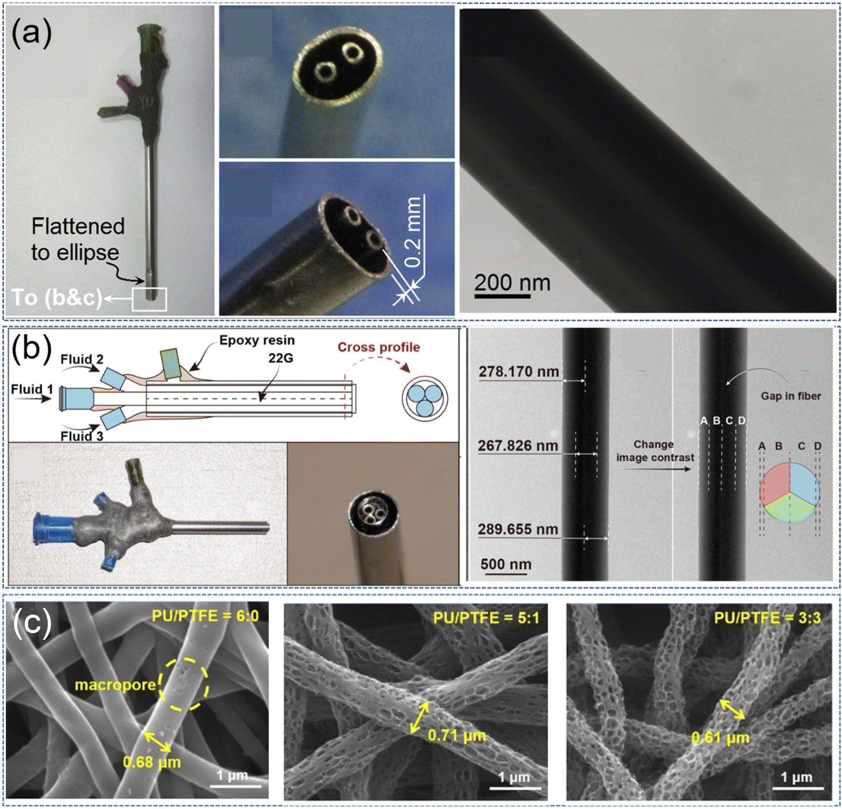 | ||
| Fig. 5 (a) A spinneret for preparing fibers with a sheath-separated core structure and corresponding fibers. Reproduced with permission from ref. 64. Copyright 2020 Elsevier. (b) A spinneret for preparing embedded Janus fibers and corresponding fibers. Reproduced with permission from ref. 65. Copyright 2023 Elsevier. (c) Porous electrospun carbon fibers prepared by template method. Reproduced with permission from ref. 66. Copyright 2021, American Chemical Society. | ||
Ordered multistage porous (macro/meso/microporous) flexible ECNFs can be fabricated by varying the ratio of sacrificial templates in the precursor solution. Xia et al. prepared multilayer porous ECNFs by electrospinning using PVA and water-based polyurethane (PU) carbon precursors, polytetrafluoroethylene (PTFE) microporous templates and boric acid (BA) crosslinker.66 When the mass ratio of PU/PTFE was reduced from 6![[thin space (1/6-em)]](https://www.rsc.org/images/entities/char_2009.gif) :0 to 5:1 and 3:3, the ECNFs diameter did not change significantly, but the ECNFs surface became rougher and the pore size gradually increased (Fig. 5c). Porous ECNFs can be customized by varying the amount of PU and PTFE.
:0 to 5:1 and 3:3, the ECNFs diameter did not change significantly, but the ECNFs surface became rougher and the pore size gradually increased (Fig. 5c). Porous ECNFs can be customized by varying the amount of PU and PTFE.
2.2. Modification of electrospun carbon nanofibers
ECNFs generally are converted from polymeric nanofibers through two processes: electrospinning and calcination. There are many polymers available for spinning, some common examples are polyacrylonitrile (PAN), polyimide (PI), polymethylmethacrylate (PMMA), polyvinyl alcohol (PVA), polyvinylidene fluoride (PVDF), lignin and pitch.68,69 Most of the spinnable polymer-derived ECNFs have high carbon yields, and desirable mechanical properties, but relatively low SSA and active sites limit their application in SCs. Therefore, it is necessary to rationally design its functional group structure, pore, and composite structure to gradually improve its physical and chemical properties. Despite the many excellent properties of ECNFs, modification of the ECNF surface is necessary to enhance its performance as an electrode for SCs. Many methods have been reported for the surface treatment of ECNFs, such as plasma treatment, heat-induced treatment, oxidative treatment, grafting, and UV treatment.70–74 All these surface treatments are designed to improve the interfacial properties by improving the wettability, surface roughness, or surface chemical bonding. Surface chemical bonding can enhance the hydrophilicity of ECNFs and make good contact between ECNFs and electrolytes, thus improving the electrode conductivity. Surface roughness can result in a larger surface area to increase the number of active sites. In addition, to further enhance the comprehensive performance of ECNFs, it is often necessary to compound ECNFs with other materials. The popular methods include layer-by-layer, dip-coating, and in situ polymerization.75–773. Electrospun carbon-based nanofibers for supercapacitors
SCs consist of electrodes, electrolytes, separators, and collectors. Among them, the electrode is the core component, which is responsible for the storage of charge.78 The charge storage capacity of SCs is directly influenced by the performance of the electrode material. Electrodes are usually prepared using materials with high SSA, good electrical conductivity, and excellent electrochemical stability. ECNFs that can meet the requirements of electrode materials for SCs can be prepared using electrospinning techniques. Since Kim et al. first reported ECNFs for SCs, the field has been developing for nearly two decades, and various strategies have been devised to improve the performance of SCs (Fig. 6).79–88 Most of the spinnable polymer-derived ECNFs have high carbon yields, and desirable mechanical properties, but relatively low SSA and active sites limit their application in SCs. Therefore, it is necessary to rationally design its functional group structure, pore, and composite structure to gradually improve its physical and chemical properties. In this section, we discuss the effect of the functional group structure of ECNFs on the electrochemical performance of electrodes. Then, an overview of electrospinning methods for the preparation of porous ECNFs is presented, focusing on multi-structural design to improve the performance of SCs. | ||
| Fig. 6 A brief summary of the development historical of ECNFs for SCs. | ||
3.1. Design of functional group structures
In general, surface functional groups of carbon materials improve the physicochemical properties of ECNFs by altering the band gap cations, generating oxygen vacancies and increasing the carrier density. When heteroatom functional groups are introduced into ECNFs, the ordering of the carbon atoms surrounding the heteroatoms is disturbed, resulting in lattice distortion of the carbon material and thus the formation of defects. Heteroatoms in the carbon structure not only act as electron donors to increase the electrical conductivity of the material, but also modulate its surface chemistry, improve the wettability of the electrodes, and contribute to the enhancement of the adsorption/desorption of electrolyte ions. In addition, the heteroatoms can participate in Faraday redox reactions as active sites, providing pseudocapacitance for the electrodes.PAN is a commonly used N-containing polymer, most ECNFs are N-doped ECNFs (NECNFs). NECNFs usually contain four bonding types: pyridine N (N-6), pyrrole N (N-5), quaternary N (N-4), and oxidized N. Different bonding types of N-doped structures have various functions in the energy storage process of ECNFs.89–91 Typically, there are two doping methods, one is adding material containing heteroatoms to the precursor solution and carbonizing them directly after electrospun, named in situ doping. The other is doping with heteroatoms by subsequent treatment after electrospun, named post-doping. Multiple heteroatoms co-doped ECNFs can be synthesized through in situ doping or post-doping methods using additional elements, such as N/S, N/P, N/B, and so on. The multiple heteroatoms in the co-doped ECNFs can produce clever synergistic effects, which can further enhance the electrochemical performance of the electrodes. For example, N heteroatoms in carbon can enhance electron-donating properties and O functional groups can enhance electron-accepting properties. They usually cooperate more to significantly enhance the Faraday reaction that generates pseudocapacitance. In addition, co-doping of oxygen and nitrogen atoms may form alternating hydrophilic and hydrophobic nanodomains on the surface of the carbon material, capable of inducing surface amphiphilicity in aqueous and ionic liquid electrolytes. The synergistic effect of co-doping can modulate the crystal and electronic structure of electrode materials by maintaining the advantages of each dopant or suppressing the disadvantages of other dopants, thus enhancing the electrochemical performance of electrode materials. In N, S co-doped carbon, S doping can significantly increase the N-6 content. Due to the synergistic effect, the additional N-6 and S provide more active sites for ECNF.92
N doping can be achieved by adding N-rich substances to the precursor solution. For example, using PAN as a spinning substrate and providing N source, templates such as PMMA, PVP, and PEG were added to modulate the pores and N content, and the NECNFs obtained all had high Cs.93–96 As mentioned earlier, ECNFs with porous structures were obtained by introducing copolymers into PAN chains. Because PAN is a N-containing polymer, the ECNFs obtained by this method were also doped with certain N-atoms. Li et al. enhanced the ECNFs N doping further by introducing an O-rich monomer (itaconic acid, IA) into the PAN chain (Fig. 7a).89 The abundance of pyridine-N and pyrrole-N/pyridine-N in ECNFs contributed pseudocapacitance to the electrodes derived from the N-doped material via Faraday reactions. The Cs was increased to 347 F g−1 (0.5 A g−1) when NECNFs were used as an electrode material for SCs. In addition, the prepared flexible and fine SCs have excellent flexibility and utility. Yan et al. carbonized and activated PAN/dicyandiamide composite nanofibers to obtain highly graphitized PAN-derived ECNFs with cross-linked structures and profuse N-atoms.94 The capacitance can be increased, and electron transfer can be promoted through the positive charge density of quaternary N (N-Q). Correspondingly, NECNFs showed a high Cs of 323 F g−1 (0.5 A g−1) in the three-electrode system. In addition to adding N-rich substances to the precursor solution, N-atoms can also be doped into NECNFs by in situ polymerization or chemical grafting after electrospinning.97–99 Liu et al. implanted polyaniline into PAN-based electrospun nanofibers by in situ polymerization, and the NECNF obtained was doped with 5.9 at% conductive and 4.73 at% of reactive N-atoms (Fig. 7b).97 N-atoms are evenly distributed on the surface of the fiber. Due to the presence of N-atoms, NECNFs impose a dense pair of symmetrical redox peaks on a equirectangular curve, which can be observed even at high scan rates of 500 mV s−1. It tested 90000 cycles at a current density of 20A g−1, showing exciting long-term cycle performance. The solid-state SCs made of these NECNFs can perform a specific energy and power density of 18.3 W h kg−1 and 16.9 kW kg−1, and it also lights up with LEDs. Its excellent electrochemical performance is derived from the synergistic effect of ultrahigh-synchronous conductive-active nitrogen doping and high SSA. NECNFs can be successfully synthesized during carbonation through N-rich substances.100–102 Furthermore, NECNFs can also be doped after the carbonization of electrospun nanofibers. For example, chemical vapor deposition (melamine), hydrothermal method (urea, tetra-2-pyridinylpyrazine), in situ polymerization (polyaniline).103–108
 | ||
| Fig. 7 (a) Schematic of the carbonization of P(AN-co-IA) copolymer and the properties of the prepared flexible devices. Reproduced with permission from ref. 89. Copyright 2021, American Chemical Society. (b) The scheme diagram of the polyaniline was synthesized in situ on electrospun carbon nanofibers. Reproduced with permission from ref. 97. Copyright 2022, Elsevier. | ||
Apparently, single doping can improve the higher pseudocapacitance for ECNFs-derived electrode materials. However, the enhancement of electrochemical properties by single doping is limited. To further enhance the electrochemical performance, multiple elements (O, S, P, B) can be doped into the material. Single heteroatom with limited content doping is not as favorable as multi-heteroatom doping with synergistic effects for the overall electrochemical performance.
The O element present in electrospun nanofibers usually arises from insufficient combustion of the polymer in the nanofibers.109–113 By pre-oxidizing electrospun nanofibers before carbonization, O-containing functional groups can be introduced into the fibers, leading to incomplete carbonization of the fibers. While the introduction of O-containing functional groups can enhance the wettability of ECNFs and increase the number of redox-active sites, excessive introduction of O atoms can reduce the cycle life of ECNFs. Despite being in the same main group as N and having a higher electron-donating capacity, the effect of P doping on the carbon structure and electrochemical mechanism remains unclear, unlike the extensively studied N doping. Liu et al. proposed that the doped P atoms have a positive impact on the capacitance rate performance of the materials.114 This is due to the P atoms readily reacting with the O-containing functional groups on the surface of electrospun ECNFs to create more stable P–O compounds, which are embedded in the carbon material's surface. During charging and discharging, the doped P atoms reduce the consumption of O-containing functional groups on the carbon material's surface, thereby enhancing its stability.115,116
The electrochemical properties of ECNFs are similarly enhanced when doped with B atoms, especially at low B doping concentrations, where B has a catalytic effect on carbon oxidation, contributing to enhanced hydrophilicity and adding additional pseudocapacitance.117,118 Although the doping of S and F in ECNFs equally enhances the performance of SCs with ECNFs as the electrode material, the S functionalization leads to a significant decrease in SSA of ECNFs, while F doping is understudied due to the limited F source and low doping level.119–121
Apart from adding P, B, S, or F atoms individually to the ECNFs, simultaneously introducing two or more heteroatoms can also be effective.122,123 Co-doping with multiple atoms can produce synergistic effects and lattice defects between heteroatoms, increasing electrochemical activity (Table 2).
| Heteroatoms | Elemental contents | Capacitance | Cycle performance (capacitance retention) | References |
|---|---|---|---|---|
| N, O | 5.80, 5.60 (at%) | 367.0 F g−1 at 0.50 A g−1 | 93.00% after 10000 cycles at 10.0 A g−1 |
100 |
| N, O | 3.40, 4.29 (at%) | 261.0 F g−1 at 1.00 A g−1 | 94.00% after 10000 cycles at 10.0 A g−1 |
109 |
| N, O | 3.41, 7.68 (at%) | 233.1 F g−1 at 0.20 A g−1 | 90.17% after 4000 cycles at 2.0 A g−1 | 110 |
| N, O | 7.84, 11.43 (wt%) | 320.0 F g−1 at 1.00 A g−1 | 94.50% after 5000 cycles at 1.0 A g−1 | 113 |
| N, O, P | 10.91, 4.04, 0.37 (at%) | 288.7 F g−1 at 0.50 A g−1 | No attenuation after 5000 cycles at 2.0 A g−1 | 114 |
| N, O, B | — | 309.0 F g−1 at 0.25 A g−1 | 94.00% after 10000 cycles at 1.0 A g−1 |
117 |
| N, O, B | — | 200.2 F g−1 at 0.10 A g−1 | 104.81% after 3000 cycles at 3.0 A g−1 | 118 |
| N, O, S | 7.80, 5.50, 1.40 (at%) | 396.0 F g−1 at 1.00 A g−1 | 107.00% after 3000 cycles at 15.0 A g−1 | 120 |
| N, O, P, S | — | 584.8 F g−1 at 0.20 A g−1 | 93.50% after 10000 cycles at 1.0 A g−1 |
122 |
3.2. Design of pore structures
To improve the electrochemical properties of ECNFs, electrospun nanomaterials with different morphologies such as hollow, porous and core–shell have been successfully synthesized.124,125 Electrode materials with hollow structures not only reduce the diffusion path of electrons and ions but also can store charges, which is beneficial to the electrochemical performance of the materials. Asare et al. found that the Cs of these ECNFs is mainly determined by the mesopore volume and total pore volume.126 The total pore volume reflects the amount of charge that can be adsorbed, while the mesopore volume controls the electrolyte resistance. Therefore, the electrochemical performance of ECNFs is determined by a variety of factors and cannot be judged by the SSA alone. The diameter of ECNFs also affects their electrochemical properties.127 Considering the mechanism of energy storage in SCs, the effect of different pore sizes on the process of energy storage in the electrodes may be different.128–130 Micropores present a high SSA, which facilitates charge storage and determines the capacitive performance of the electrode material. Mesopores facilitate electrolyte transport and can provide a higher power density, while macropores facilitate electrolyte transport to micropores and mesopores, making adsorption easier. The ECNFs can be made to form a porous structure by introducing sacrificial templates into the precursor solution. In addition, PECNFs can be obtained not only by introducing gases such as water vapor, CO2, and air during the calcination process, but also by using chemical reagents such as KOH, NaOH, and phosphoric acid. According to the different ways of pore generation, it can be divided into templating methods and etching methods. Templating methods can be further divided into inorganic templates and organic templates, while the etching methods mainly include physical etching and chemical etching.141:2) of ECNFs facilitates the electrolyte ions to reach the interior surface of the porous carbon, thus enhancing the double-layer capacitance. The two-electrode system exhibits a high capacitance of 210.7 F g−1 at 0.2 A g−1 and boasts outstanding cycling stability. During the pyrolysis of carbon precursors, inorganic salts such as CaCO3, NaHCO3, Co(NO3)2, Mg(NO)3 can decompose into metal oxides and can also serve as inorganic templates to create pores.133–135,142 Zhang et al. prepared multistage porous ECNFs using PAN as a carbon precursor and nano CaCO3 as a template.142 As shown in Fig. 8a, Liu et al. prepared multistage porous structured ECNFs after the following steps: electrostatic spinning, carbonization and template removal. The electrode demonstrated excellent performance in a two-electrode system. Although metal oxides can also be used as inorganic templates, they require acids for removal and because they are insoluble in polymer solutions, they collect at the spinneret and clog the spinneret.136,137
 | ||
| Fig. 8 (a) Schematic and electrochemical properties of electrospun porous carbon nanofibers prepared using CaCO3 as a template in a two-electrode system reproduced with permission from ref. 142. Copyright 2016 Elsevier. (b) Steps of preparing electrospun porous carbon nanofibers by SiO2 as a template, carbonization and etching after electrospinning, SEM images of fibers in corresponding steps and electrochemical performance in two-electrode system. Reproduced with permission from ref. 138. Copyright 2016 Elsevier. | ||
SiO2 is commonly used as an inorganic template for the preparation of layered porous nanomaterials due to its ease of tuning various morphologies and sizes.138–140,145 As shown in Fig. 8b, after carbonization, the uniformly dispersed SiO2 in the fibers is efficiently removed by NaOH, and ECNFs with conjugated surfaces and interconnected macroporous structures were obtained.138 Unexpectedly, the conjugated macroporous ECNFs showed excellent performance in the two-electrode system.
Despite this, there are relatively few reports on the use of porous nanomaterials prepared from SiO2 for SCs electrodes, this is because they need to be removed with hydrofluoric acid or corrosive strong alkaline solutions. The summary of the inorganic templates for the modification of the pores of ECNFs is shown in Table 3.
| Materials | Templates | SSABET (m2 g−1) | Performance | References |
|---|---|---|---|---|
| HPECNFs | KCl/K2CO3 | 726.0 | 293.0 F g−1 at 0.2 A g−1 | 131 |
| HPECNFs | K2S | 835.0 | 210.7 F g−1 at 0.2 A g−1 | 132 |
| PECNFs | Co(NO3)2 | 468.9 | 104.5 F g−1 at 0.2 A g−1 | 133 |
| PECNFs | Mg(NO3)2 | 1140.0 | 248.0 F g−1 at 0.2 A g−1 | 134 |
| Cross-linked ECNFs | ZnCl2 | 520.0 | 214.0 F g−1 at 1.0 A g−1 | 135 |
| Inner PECNFs | SnO2 | 967.0 | 328.0 F g−1 at 1.0 A g−1 | 136 |
| Porous ultrathin ECNFs | ZnO | 588.0 | 155.0 F g−1 at 10.0 A g−1 | 137 |
| Meso–microporous ECNFs | SiO2 | 60.0 | 242.0 F g−1 at 0.2 A g−1 | 138 |
| PECNFs | SiO2 | 496.5 | 247.8 F g−1 at 1.0 A g−1 | 139 |
| Bubbled ECNFs | SiO2 | 593.0 | 287.0 F g−1 at 0.4 A g−1 | 140 |
Organic templates can not only provide ECNFs with pores of different sizes but also provide them with a carbon source. Due to the difference in properties between the organic template and the spinning polymer, the organic template can be removed by carbonization or other methods. Commonly used organic templates are tetraethoxy orthosilicate (TEOS), organic polymers, and organic salts.
TEOS is soluble in spinning precursors, and undergoes conversion to SiO2 upon heat treatment, making it a popular choice for the preparation of porous ECNFs146–150 Kim et al.147 obtained Si/ECNFs with a high SSA and high microporous structure with a surface area up to 1386.91 m2 g−1, energy density within 15.0–22.3 W h kg−1, and power density within 0.4–100 kW kg−1 by adding a PAN-based precursor solution acting as a pore-forming template with a PAN/TEOS weight ratio of 8/2. TEOS can be converted to its hydrated form (Si(OEt)4·nH2O) during spinning, and during stabilization at 280 °C (temperature increase rate 1 °C min−1), the Si–OEt bond is hydrolyzed to produce silanol (Si(OH)x), followed by further condensation leading to the formation of SiOx and the escape of gases such as CO2, H2, H2O etc.148 Wang's team proposed a coaxial electrospun method to prepare double capillary carbon nanofibers (DCNFs) with porous structure using TEOS/ethanol solution for the external fluid and lignin/dimethylformamide (DMF) for the internal fluid, as shown in Fig. 9a.149 The SSA of these DCNFs can reach 870 m2 g−1, which is larger than that of the porous ECNFs (568 m2 g−1) and ECNFs (164 m2 g−1) used as controls. Among the tested materials, when the current density was increased from 1 A g−1 to 20 A g−1, DCNFs stood out with an impressive capacitance retention of 74%. In comparison, porous ECNFs and ECNFs displayed retention rates of 54% and 40%, respectively. Furthermore, after 4000 cycles at a current density of 10 A g−1, it was able to reach 94% of the initial capacitance. What is surprising is that the assembled flexible device shows excellent performance after bending. Cui et al. prepared bamboo-like ECNFs with ideal porosity using TEOS as a template, which could achieve excellent electrochemical performance.150 As shown in Fig. 9b, the precursors of PAN and TEOS in DMF were formed into nanofibrous nets by electrospinning. Bamboo-like ECNFs were obtained by heat-treating TEOS/PAN nanofiber networks in H2/Ar (5/95 volume fraction) atmosphere and then etching SiO2 in HF aqueous solution. The SSA of the bamboo-like ECNFs is as high as ∼1912 m2 g−1 calculated in the range of 0.05–0.25 P/P0 by the Brunauer–Emmett–Teller (BET) model and the total pore volume is ∼2.27 cm3 g−1 evaluated at a single-point adsorption at P/P0 = 0.98. The pore volume for micro- and mesopores is ∼1.87 cm3 g−1. In addition, the assembled flexible electrode can be bent at will, showing excellent flexibility.
 | ||
| Fig. 9 (a) Schematic diagram of the fabrication process for double capillary carbon nanofibers, and CV curves of related flexible devices under normal and bending conditions. Reproduced with permission from ref. 149. Copyright 2016, Elsevier. (b) Schematic diagram of the fabrication process of the bamboo-like carbon nanofibers and demonstration of the flexibility of the corresponding flexible electrodes. Reproduced with permission from ref. 150. Copyright 2015, American Chemical Society. (c) The detailed sequential process of etching PVP and constructing porosity on the MPNFs, and cycling performance of flexible devices. Reproduced with permission from ref. 121. Copyright 2018, Royal Society of Chemistry. | ||
Organic polymers such as polyacrylic acid (PAA), PMMA, polystyrene (PS), and polyethylene glycol (PEG) can be used as sacrificial templates due to their different properties.96,151–155 When PVP is co-mingled with PAN, PVP is also commonly used as a sacrificial template.121,156–159 PVP is more hydrophilic than PAN and can therefore be extracted from PAN nanofibers during hydrothermal treatment to produce mesoporous PAN nanofibers. The formation mechanisms of the observed changes in nanofiber structure and porosity are described (Fig. 9c).121 During hydrothermal treatment, the residual PVP in the PAN fibers agglomerates with each other, with the agglomerated PVP and the fiber shell separating from the PAN core. Since the molecular weight of PVP is higher than that of PAN, an increase in PVP content increases the viscosity and surface tension of the electrospinning precursor solution, increasing the diameter of the fibers produced.121,156 The ECNFs derived from PVP–PAN electrospun nanofibers have high porosity and SSA, and PVP is an N-rich polymer that provides a certain pseudocapacitance for the ECNFs, presenting excellent electrochemical properties.90,158 Ultrasonic treatment of PVP–PAN electrospun nanofibers also removes PVP and can obtain ultrafine ECNFs with a porous multilayer structure.159
Although ECNFs with porous structures can be prepared by blending polymers and sacrificing templates, the uniformity of pore size is difficult to control. Zhou et al. proposed a method for the synthesis of hierarchical ENCFs with highly controlled structures by introducing block copolymer self-assembly.151 The ECNFs exhibit hierarchically interconnected mesopores and micropores with a surface area of up to 503 m2 g−1 and an exciting superior electrochemical performance (Fig. 10a). Moreover, substances like coal, asphalt, and lignin also can be utilized as templates in the production of porous ECNFs.161–164
 | ||
| Fig. 10 (a) SEM images of the electrospun carbon fibers from PAN/PMMA, and PAN-b-PMMA and electrochemical properties of electrospun carbon nanofibers. Reproduced with permission from ref. 151. Copyright 2019, The American Association for the Advancement of Science. (b) Schematic preparation of MOFs-based porous ECNFs and their application in flexible SCs. Reproduced with permission from ref. 160. Copyright 2023, Elsevier. | ||
Organic salts, such as tetramethylammonium oxalate (TMAO), manganese acetate (Mn(OAc)2), and copper acetate (Cu(OAc)2) can act as pore-forming agents in a similar principle to the inorganic salt templates.165–169 The difference is that most organic salts are well soluble in polymers and can avoid the inhomogeneous pore structure caused by the dispersion of the template. Among them, many organometallic salt templates require acids for removal, while organic ammonium salts can be pyrolyzed during carbonization and can reduce the environmental pollution from acids.170
Metal complexes such as metal–organic frames (MOFs) and manganese acetylacetonate can also form pores on ECNFs after removal.140,160,171–173 Utilizing the self-templating properties of MOFs, MOFs were combined with electrospinning as a precursor for porous carbon for energy and environmental applications. In a study by Wang et al. Zn-based MOFs were embedded in lignin-based electrospun nanofibers and carbonized as an electrode for high-performance SCs, and offer potential applications for the development of portable wearable devices.160 As shown in Fig. 10b, upon carbonization at elevated temperatures, elemental Zn in the MOFs particles is reduced to metallic Zn and evaporated at carbonization temperatures above its boiling point, ultimately forming hollow-based particles inside the ECNFs. In addition, the SCs they assembled possessed good electrochemical properties. Upon carbonization, pyrolysis of MOF could introduce abundant mesopores for ECNFs for fast electrolyte ion channels. The doping of ZIF-8 greatly not only enlarged the SSA and mesopore volume but also increased the use of certain templates can leave materials with pseudocapacitance to remain in the ECNFs. So, the choice of different templates has varying effects on the porosity and surface area of the ECNFs, as well as on the enhancement of their electrochemical performance (Table 4). Even the use of the same template can result in different outcomes.
| Materials | Templates | SSABET (m2 g−1) | Capacitance | Cycle performance (capacitance retention) | References |
|---|---|---|---|---|---|
| Bamboo-like ECNFs | TEOS | 1912.0 | 236.0 F g−1 at 5.0 A g−1 | 95.0% after 5000 cycles at 1.0 A g−1 | 146 |
| ECNFs | TEOS | 870.0 | 245.0 F g−1 at 0.5 A g−1 | 94.0% after 10000 cycles at 4.0 A g−1 |
149 |
| Flexible ECNFs | TEOS | 2292.0 | 274.0 F g−1 at 0.1 A g−1 | ∼100% after 5000 cycles at 10 A g−1 | 150 |
| PECNFs | PMMA | 503.0 | 360.0 F g−1 at 1.0 A g−1 | ∼100% after 10000 cycles at 100.0 A g−1 |
151 |
| PECNFs | PMMA | 503.0 | 334.0 F g−1 at 1.0 A g−1 | 98.0% after 5000 cycles at 100.0 A g−1 | 96 |
| PECNFs mats | PMMA | 683.5 | 140.8 F g−1 at 0.5 A g−1 | 92.0% after 20000 cycles at 1.0 A g−1 |
154 |
| Mesoporous ECNFs | PVP | 596.1 | 252.6 F g−1 at 0.5 A g−1 | 95.4% after 10000 cycles at 10.0 A g−1 |
121 |
| Microporous ECNFs | PVP | 406.4 | 200.0 F g−1 at 0.5 A g−1 | 93.0% after 1000 cycles at 1.0 A g−1 | 158 |
| ECNFs mat | Coal | 616.8 | 227.4 F g−1 at 1.0 A g−1 | 104.3% after 10000 cycles at 5.0 A g−1 |
162 |
| Cross-linked ECNFs | Pitch | 643.0 | 187.0 F g−1 at 1.0 A g−1 | 84.0% after 3000 cycles at 5.0 A g−1 | 164 |
| ECNFs | Co(Ac)2 | 338.6 | 256.5 F g−1 at 0.5 A g−1 | 84.7% after 1500 cycles at 1.0 A g−1 | 166 |
| ECNFs | MOF | 1440.0 | 396.0 F g−1 at 1.0 A g−1 | 107.0% after 3000 cycles at 15.0 A g−1 | 120 |
| HPECNFs | MOF | 111.3 | 664.4 F g−1 at 1.0 A g−1 | 83.1% after 5000 cycles at 10.0 A g−1 | 170 |
| Micro–mesoporous ECNFs | Acetylacetonate | 563.0 | 272.0 F g−1 at 1.0 A g−1 | 96.7% after 3000 cycles at 100 mV s−1 | 173 |
| HPECNFs | PMMA/TEOS | 1126.0 | 207.0 F g−1 at 0.2 A g−1 | ∼99.0% after 8000 cycles at 1.0 A g−1 | 91 |
 | ||
| Fig. 11 (a) Schematic diagram of the process for the preparation of porous electrospun carbon nanofiber membranes, including electrospinning, imidization, carbonization and H2O2 activation. Reproduced with permission from ref. 174. Copyright 2022, Elsevier. (b) Schematic diagram of CNFs preparation by electrospun, carbonization and KOH activation. Reproduced with permission from ref. 181. Copyright 2019, Elsevier. (c) Phosphoric acid-activated electrospun nanofibers with high SSA even after carbonization at 1600 °C. Reproduced with permission from ref. 115. Copyright 2022, Elsevier. | ||
The symmetric SCs they made from these ECNFs were able to light up LEDs. ECNFs obtained by etching the electrospun nanofibers with water vapor have a desirable SSA and pore volume, especially the micropore volume, and exhibit excellent performances in the SCs system.175 Abeykoon et al. activated electrospun fibers with CO2 during carbonization.176 Abeykoon et al. activated electrospun fibers with CO2 during carbonization.176 The resulting ECNFs have a high SSA of 3010 m2 g−1 and a total pore volume of 1.6077 cm3 g−1, of which the microporous volume is 0.9205 cm3 g−1, accounting for 57.2%. The size of the micropores/mesopores that are formed is very similar to the size of the electrolyte ions, which results in more sites for charge transfer.178 The capacitance of the CO2-activated ECNFs is enhanced from 97.0 F g−1 to 136.7 F g−1 (10 mV s−1) and the energy density from 49 W h kg−1 to 79 W h kg−1 (10 kW kg−1) compared with that of the normal ECNFs.180 During CO2 activation, the fiber surface is etched by CO2, which leads to a decrease in fiber diameter while increasing SSA. This results in a narrow charge diffusion pathway and large porosity exhibited between fibers, finally causing an enhancement of electrochemical properties.176,177 Although water vapor can also be used to activate ECNFs and lead to an increase in micropores, it leads to ECNFs with lower conductivity and lower SSA relative to etching with CO2.175,178 However, this did not result in a higher Cs of the CO2-activated ECNFs. Because the H2O-activated ECNFs have a suitable pore size to accommodate the electrolyte ions, allowing for a large capacitance.154 Through the reaction between the gas and the carbon atoms on the surface not only generates new pores, but also has a pore-opening effect, and the volatilization of the gas during the heating process can expand the closed pores and enrich the pore structure. In addition, when the oxidizing gas reacts with part of the pores, it can also make the pores expand and thus increase the width of the pores.
Some common bases (KOH, NaOH) and acids (H3PO4, HNO3) could corrode carbon structure of nanofibers, thereby allowing ECNFs to obtain a porous structure.115,164,181–188 Among them, KOH is the most used because it has low pyrolysis temperature requirements and can produce satisfactory porosity.181–185 As shown in Fig. 11b, the nanofiber mats were first prepared by electrospinning, and ECNFs were formed after carbonization at a certain temperature, followed by mixing with KOH and activation at high temperature.181 The reactions during the activation process are as follows:48,181
| 6KOH + 2C → 2K + 3H2 + 2K2CO3 | (1) |
| K2CO3 → K2O + CO2 | (2) |
| CO2 + C → 2CO | (3) |
| K2CO3 + 2C → 2K + 3CO | (4) |
| C + K2O → 2K + CO | (5) |
Singh et al. obtained the nanofiber mats by electrospun a mixture of lignin and PVA, and the ECNFs were prepared by pre-carbonation at 600 °C followed by activation with KOH at 800 °C.182 The activated ECNFs were made into all-solid-state SCs devices due to high flexibility, independence, and excellent electrode performance. The devices exhibited a high energy density of 65.52 W h kg−1 and a power density of 1036.27 W kg−1 with high coulombic efficiency (99.6%) after 10000 cycles. However, the usual activation with KOH requires the use of highly corrosive hydrochloric acid for cleaning. It was found that by using lignin as the spinning material and adding HNO3 for activation (Fig. 11c), the resulting ECNFs not only possess a porous structure but also have the presence of P elements, which in turn enhances the performance of the electrode.115 The addition of phosphoric acid shortened the thermal stability time of the fiber, increased the carbonization yield, generated phosphorus functional groups (P content up to 3 wt%), and increased the BET SSA of carbon fiber from 840 m2 g−1 to 1143 m2 g−1. Even after high-temperature carbonization at 1600 °C, the 822 m2 g−1 of SSA was retained. Pore creation with acid and alkali requires lower temperature and shorter time than gas etching, which can avoid pore rupture due to too high temperature and too long time. On the other hand, it is also more activated, which allows the fabrication of ECNFs with unique pore structures but suffers from high cost, equipment corrosion, and activator residue. Moreover, the porosity and surface chemistry of ECNFs are greatly affected by the activation temperature.
3.3. Design of composite structures
Despite efforts to improve performance by using electrode materials with high SSA and heteroatom doping, this remains challenging due to the limitations of the electrical double-layer capacitance storage mechanism. When compounded with materials such as transition metal compounds and conducting polymers, a synergistic effect is achieved, proving to be an effective approach.189–193 The physical modification of carbon materials is mainly reflected in the contrast surface area, pore structure, and the improvement of electrical conductivity.194–196 Through surface/interface engineering, it is possible to realize the construction of composite structures system systems and multi-component synergistic effects of carbon materials with other materials, which is conducive to the enhancement of the conductivity of materials and the stability of energy storage devices.197–199In addition to the regulation of pore structure and the introduction of heteroatoms into ECNFs, many researchers have attempted to design multi-structural systems to achieve the complementary advantages of different structures and improve the overall electrochemical performance of electrode materials.200,201 ECNFs obtained by adding other structured materials (carbon, MOFs, MXene or others) to the precursor solution are called internal structure designs. In contrast, the design of multilayered structures obtained by post-treatment of electrospinning is called external structural design, which includes treatment on single fibers or fiber membranes.
000 times without significant capacitance degradation. In addition, the AGRCNF-3 fabric can return to its initial shape after more than 100 cycles of gripping, folding, and twisting, demonstrating its excellent flexibility and durability. Interestingly, the folded AGRCNF-34 fabric with a thickness of only 3 μm (700 mg) can pull up to 200 g, demonstrating its superior mechanical strength to most porous carbon fabrics. The excellent electrochemical properties and mechanical strength of ECNFs derive from the complete reinforcing phase and conductive network constructed within the fibers by highly crystalline GQDs.
 | ||
| Fig. 12 (a) Schematic diagram of area graphene quantum dots reinforced carbon nanofiber prepared through electrospinning, carbonization, and chemical activation, and mechanical properties of materials. Reproduced with permission from ref. 204. Copyright 2021, American Chemical Society. (b) Schematic diagram of the production of Ti3C2Tx MXene/ECNFs via electrospinning, and cycling performance of MXene/ECNFs electrodes. Reproduced with permission from ref. 206. Copyright 2019, Royal Society of Chemistry. (c) Schematic diagram and morphology of one-pot deposition of coaxial bilayer MnO2/Ni(OH)2 ECNFs. Reproduced with permission from ref. 207. Copyright 2022, Springer Nature Limited. | ||
Similarly, the introduction of other carbon materials such as CNTs and carbon black into ECNFs through blending can also improve its physical properties as well as their structure, thereby thus enhancing its electrochemical properties.208,209 Inspired by the natural phenomenon of “lotus root may break, but the fiber stays connected”, Zhu et al. prepared hollow porous carbon nanofibers bridged by carbon nanotubes using coaxial electrospun technique.77 The addition of multi-walled CNTs prevent the porous structure of the fibers from damaging their mechanical properties.
In addition to the introduction of carbon-based materials into ECNFs, many compounds were also used to design the internal structure of ECNFs as well.210,211 Levitt et al. added metal carbides and nitrides (MXene) to the spinning solution to prepare MXene/ECNFs (Fig. 12b).206 The MXene/ECNFs electrode and a pure carbon electrode were cycled for 10000 cycles, revealing stable performance at 50 mV s−1. Metal compound with relatively low reduction temperature and excellent ductility is a good candidate as a reinforcing phase for ECNFs.212 Zhao et al. reported a highly flexible ECNFs that introduce Sn particles.213 Due to the introduction of ductile Sn, the ECNFs were able to be repeatedly wound on glass rods without breaking. In addition, the reinforced ECNFs can be directly used as electrodes with a specific capacitance of 342.05 F g−1 at 0.5 A g−1 current density. In addition, the metal salts and MOF templates talked about in Section 3.2 in not only bring the ideal pore structure for ECNFs, but the metal oxides left behind after pyrolysis can also enhance the capacitance of ECNFs.
Embedding the reinforcing phase with excellent mechanical strength into ECNFs can prevent their pore collapse during calcination. On the other hand, the reinforcing phase is inserted into the ECNFs as if it were a nail, which makes it possible to maintain an intact membrane morphology when subjected to external forces. The relevant studies are summarized in Table 5.
| Materials | Electrochemical performance | Mechanical performance | References |
|---|---|---|---|
| Graphene-ECNFs | 283.0 F g−1 at 0.2 A g−1 | — | 202 |
| GQDs-ECNFs | 319.0 F g−1 at 0.5 A g−1 | Young's modulus value is 226.0 MPa | 203 |
| GQDs-ECNFs | 335.0 F g−1 at 1 A g−1 | Can pull up a weight of 200 g | 204 |
| CNTs-ECNFs | 164.6 F g−1 at 1.0 A g−1 | Tensile strength of 54.8 MPa | 208 |
| Carbon black-ECNFs | 166.0 F g−1 at 0.1 A g−1 | — | 209 |
| Va/Co oxides-ECNFs | 1.83 F cm−2 at 8.0 mA cm−2 | 5.5% Cs degradation of assembled flexible devices after 180 degrees of bending | 211 |
| MXene-ECNFs | 205 mF cm−2 at 50.0 mV s−1 | Ability to wrap around vials | 206 |
| W2C-ECNFs | 256.0 F g−1 at 1.0 A g−1 | — | 212 |
As the second category, electrodes for high-performance stand-alone SCs can be prepared by preparing multilayer ECNFs membranes through multiple electrospun.220–222 Kim et al. designed a sandwich structure that stabilizes the MnO2 particles encapsulated in the middle layer as active sites to provide better electrochemical performance for the electrode.220 In another of their studies, urea was introduced as a nitrogen source into the bottom (or top) layer of the sandwich structure. The doping of the N-based functional groups led to an increase in the hydrophilicity of the surface of the ECNFs, which in turn increased their electrical conductivity. This sandwich structure is designed not only to avoid the exposure of pseudocapacitive materials to the surface of ECNFs, which would lead to reduced stability but also to have an excellent conductive network that provides short ion diffusion for ions and electrons. In addition, the method of designing both internal and external structures simultaneously has been used. Du et al. fabricated an ECNFs composite based on the concept of “maximizing structure utilization”, in which NiS particles were encapsulated internally by electrospinning, while the external structure was achieved by a simple impregnation-sulfurization process in which NiS nanosheets were uniformly embedded on the surface of interconnected carbon fibers.223 This structure simultaneously realizes the dual introduction of Faraday capacitance and the assurance of the conductivity of the electrodes. The NiS nanoparticles encapsulated inside the ECNFs not only prevent severe aggregation but also act as redox activators to increase the pseudocapacitance. The NiS nanosheets anchored on the outer surface of the ECNFs can mitigate the decrease in stability caused by buildup and facilitate the transfer of electrolyte ions through a large accessible surface area. By incorporating materials with various structures into ECNFs to create multi-structured ECNFs, these ECNFs can deliver high capacitance and outstanding cycling performance, while also enhancing their flexibility.
3.4. Discussion on the structural design of electrospun carbon fibers for supercapacitors
The structural design of ECNFs has three main aspects: functional group design, pore structure design, and composite structure design.(1) Introducing unique functional groups into the carbon structure of ECNFs can enhance the conductivity of the electrodes, thus providing a certain pseudocapacitance. Commonly used doping elements in the structure of ECNFs are N, S, P, etc. According to the mechanism raised by Li et al.,224 the uniformly distributed N atoms in ECNFs provide high concentration of N-doped active sites and endow with good wettability,225 in addition, the quaternary N and pyrrolic N also could improve the capacitance by promote the interaction with electrolyte ions and pseudocapacitive contributions, respectively.226 S doping enhances ion diffusion and charge transfer at high speeds under high current densities. This rapid mass transfer across the electrode promotes both pseudocapacitive and electric double-layer capacitive behaviors.227 B doping can significantly increase surface hydrophilicity and wettability, thereby enhancing both electric double-layer capacitance and pseudocapacitance through more efficient ion penetration and interaction in carbon electrodes.228 P doping can provide more active sites for strong ion adsorption to improve electrochemical performances.229 The O doping mainly attributed to the special type, such as carbonyl (–C![[double bond, length as m-dash]](https://www.rsc.org/images/entities/char_e001.gif) O) type oxygen, –SOx (x = 1, 2), C–O–PO3 and (C–O)3PO.230,231 It should be noted that the doping of different elements results in different synergistic effects. Heteroatoms not only enhance redox pseudocapacitance but also prevent irreversible changes in oxygen-containing functional groups on the surface of carbon materials during charge and discharge.232 Due to the additive effects of triple doping, the Faraday interaction between the heteroatoms or functional groups of the electrode and the electrolyte will result in significant pseudocapacitance.233 It should be noted that the synergistic effects of two- and multi-element doping are generally considered to be complex. Most notably, the synergistic effects of several doping species can boost the specific capacitance of carbon and create stronger active areas by multi-element co-doping. More defects in the graphene lattice may be generated by the multi-element co-doping, which would activate the related C atoms and lower the activation energy needed for redox processes (resulting in a high pseudocapacitance). Moreover, a suitable arrangement and blend of heteroatoms on the surface of carbon-based materials might mitigate the early breakdown of electrolyte, leading to a greater voltage window in both organic (3.5 V) and aqueous (1.2 V) electrolytes.234,235
O) type oxygen, –SOx (x = 1, 2), C–O–PO3 and (C–O)3PO.230,231 It should be noted that the doping of different elements results in different synergistic effects. Heteroatoms not only enhance redox pseudocapacitance but also prevent irreversible changes in oxygen-containing functional groups on the surface of carbon materials during charge and discharge.232 Due to the additive effects of triple doping, the Faraday interaction between the heteroatoms or functional groups of the electrode and the electrolyte will result in significant pseudocapacitance.233 It should be noted that the synergistic effects of two- and multi-element doping are generally considered to be complex. Most notably, the synergistic effects of several doping species can boost the specific capacitance of carbon and create stronger active areas by multi-element co-doping. More defects in the graphene lattice may be generated by the multi-element co-doping, which would activate the related C atoms and lower the activation energy needed for redox processes (resulting in a high pseudocapacitance). Moreover, a suitable arrangement and blend of heteroatoms on the surface of carbon-based materials might mitigate the early breakdown of electrolyte, leading to a greater voltage window in both organic (3.5 V) and aqueous (1.2 V) electrolytes.234,235
(2) ECNFs with multistage pores can be obtained by activation, templating, and etching, The enlarged pore diameters, especially meso and macro pores, can enhance the specific surface area of ECNFs, which in turn enhances the specific capacitance based on electric double-layer capacitance behavior. Simultaneous calcination of a certain ratio of ECNFs and KOH is a common activation method to prepare porous ECNFs this method mainly generates the micro pore. Surfactant or degradable polymers are often used as templates because they can decompose upon calcination, thus leaving mainly mesopores in the ECNFs. The templating method such as SiO2, PS, could provide meso and macro pores in ECNFs compared to the activation method. The dispersible powder structure (high packing density), hierarchical porous structure (rapid ion diffusion) are usually responsible for the enhancement for supercapacitors. It should be noted that the micropores or mesopores in the ECNFs mainly provide abundant storage active sites.236 Furthermore, the macropores created by the stacking and curling of ECNFs can be utilized as a quick conduit for the movement of electrolytes.237–239
(3) The composite structure of ECNFs not only enhances the electrochemical properties of ECNFs, but also prevents the pore collapse of ECNFs during calcination, which in turn enhances the mechanical properties of the electrodes. The direct contribution of the 3D structure to the capacitance of the electrode material is limited, mainly because it only changes the morphology and macroporous structure. The composite morphology has a weak effect on the performance of the electrode material, and the composite structure plays an auxiliary and fundamental role in the capacitance performance. The advantage of the composite structure is that it may provide more possibilities for the preparation of free standing and binder free supercapacitor mats, as well as providing convenience for the preparation of the next generation of more flexible, wearable supercapacitors.142
At the same time, we also need to point out that the three points listed above are also possible directly synergistic with each other, such as the exposed mesopores and macropores doped with heteroatoms, which contribute greatly to supercapacitor's performance.
4. Conclusions
Electrospun nanomaterials are promising electrode materials for SCs owing to their superb electronic conductivity, electrolyte accessibility, rich porosity, and structural stability. This paper reviews the improvements introduced to the design of the pore structures and composition of ECNFs to enhance SCs performance. It delves into the evolution of ECNFs within the supercapacitor domain, emphasizing the symbiotic relationship between design and demand. In addition to discussing the influence of ECNFs' pore structure on electrode performance, this paper assesses pore formation techniques, including templating and etching methods. Lastly, the effects of doping treatments of ECNFs and multi-architecture designs on the performance of SCs based on ECNFs are discussed.To summarise and study the cross-section of electrospinning and supercapacitors in more depth, we searched the web of science for ‘electrospinning’ and ‘supercapacitor’ for all the literature in the past 10 years, and we selected the top 500 highly cited articles as the key data to create a research hotspot map based on the VOSviewer software (Fig. 13). We observe that the cross-cutting areas between the two researchers focus more on application performance, energy, in fact nanoparticles, nanocomplexes, fibers, fibrous membranes, and finally, some wearable, pore size, polyaniline, electrical conductivity, and mechanical properties are all topics as well. From these keywords, we believe that the application of electrospinning carbon fibers in supercapacitors includes the following main aspects:
 | ||
| Fig. 13 Research hotspots at the intersection of electrospinning and supercapacitors based on VOSviewer Software analysis. | ||
(1) The one-dimensional morphologies of ECNFs allow for facile adjustment and control, facilitating the preparation of porous ECNFs via templating or etching methods, as well as intricate structural designs. These attributes endow electrodes with unidirectional electron flow paths, excellent connectivity, high conductivity, and shortened electrolyte ion diffusion paths, thereby enhancing electrochemical performance. (2) Electrospinning provides a straightforward avenue for integrating multiple active components into a single nanofiber. The large-area fiber membrane obtained by electrospinning can be easily attached by other materials to prepare composite structures. Leveraging the synergistic effects, optimization of the interface between two or more components can yield exceptional electrochemical properties. (3) Lastly, electrospinning enables the fabrication of binderless, flexible, and wearable SC devices, paving the way for their integration into innovative applications.
5. Current challenges and outlooks
Although the advantages of this ECNFs have led to great progress in their application in the field of SCs, there are still many problems and challenges to be explored for electrospinning technology, ECNFs and SCs to reach maturity. As shown in the Fig. 14, we summarise the current challenges in the field of electrospinning carbon fibres for supercapacitors. | ||
| Fig. 14 Summary and outlook on the preparation of supercapacitor materials by electrospinning. | ||
(1) SCs, as environmentally friendly energy storage devices, necessitate the adoption of green processes for the preparation of ECNFs, a critical electrode material. In electrospinning, the evaporation of toxic and corrosive solvents presents inherent biological and environmental risks. Encouraging the use of eco-friendly solvents such as water and ethanol is imperative. Additionally, post-electrospinning, the residual spinning solution mandates the selection of sustainable, biodegradable, and cost-effective polymers and solvents.
(2) ECNFs-based SCs are storing charges through EDLC behavior, a mechanism that endows ECNFs-based SCs with high cyclic stability. However, high cycling performance is still the focus for commercially applied SCs. The cycling performance of EDLC behavior is mainly affected by two factors: the stability of the carbon structure and the pore size that matches the size of the electrolyte ions. Designing ECNFs with stable structures for SCs and providing suitable electrolytes for ECNFs are the focus of enhancing the stability of SCs. It is crucial to provide more interfaces for electrochemical reactions through interface engineering, defect construction, and electronic structure modulation. Although increasing electrochemical reaction sites may enhance SCs capacitance, it usually impairs cycling stability. Therefore, designing ECNFs with both high specific capacitance and robust stability is a major challenge. Realizing unique structural designs on the outside of ECNFs may introduce a certain amount of pseudocapacitance. However, practical challenges such as delamination of pseudocapacitive materials, poor interfacial bonding between pseudocapacitive materials and ECNFs, and impeded electron transfer must be addressed. According to most of the literature, it is known that the test standards for cycling stability of electrode materials are not uniform, which makes the evaluation basis of cycling stability of electrode materials lack of comparability. Therefore, the test conditions should be standardized to monitor the change of stability and study the decay mechanism.
(3) Attention must be directed toward the alteration of metrics during ECNFs design to enhance the electrochemical performance of SCs. Modifying the structure and morphology of nanofibers can be achieved by refining needle structure and needle arrangement and incorporating additional structures into the spinning solution to introduce more active sites for energy storage and facilitate electron transfer. Further, the commercial production of ECNFs as electrodes for SCs is pivotal, highlighting its significance. Transitioning from lab-scale production to the commercialization of ECNFs poses a significant challenge. While electrospinning has seen some level of industrialization, further exploration is needed for industrializing post-processing techniques to optimize the performance of ECNFs.
(4) Energy density, power density, internal resistance, leakage current, and output voltage are critical metrics for quantifying SCs performance. Additionally, exploring the energy storage mechanism of designed ECNFs using advanced in situ microscopy and spectroscopy techniques is crucial for enhancing the electrochemical performance of SCs. Leveraging electrospinning and molding technology, ECNFs exhibit superior mechanical properties compared to other carbon fibers, particularly in flexible energy storage devices. Through astute structural design and preventive measures to mitigate fiber collapse during carbonization, which can diminish mechanical properties, a maximal balance between mechanical and electrochemical properties can be achieved. While existing studies predominantly analyze device flexibility based on electrochemical properties under various bending conditions, there is a dearth of quantifiable metrics. Hence, designing more quantifiable performance metrics and test methods is imperative to evaluate the performance of ECNFs in flexible SCs.
(5) To advance the application scenarios of SCs, ECNFs-based energy storage systems should possess additional characteristics. For example, activities like space missions and outdoor adventures necessitate novel energy storage technologies with excellent temperature and corrosion resistance, capable of operating efficiently for extended periods. Consequently, enhancing the performance of ECNFs in extreme environments becomes imperative. Moreover, designing appropriate test methods and performance indicators may improve the relevant performance metrics.
Data availability
No primary research results, software or code have been included and no new data were generated or analysed as part of this review.Author contributions
Hailang Xu: conceptualization, writing – original draft. Bin Li: writing – review & editing, project administration, funding acquisition. Zeyu Wang: writing – review & editing. Qian Liao: writing – review & editing. Lingcong Zeng: writing – review & editing. Heng Zhang: writing – review & editing. Deng-Guang Yu: writing – review & editing. Xiaoliang Liu: writing – review & editing. Wenliang Song: supervision, writing – review & editing, project administration, funding acquisition.Conflicts of interest
There are no conflicts to declare.Acknowledgements
This work was supported by the Shanghai Sailing Program (21YF1431000), and the scientific research allowance of Dezhou University (Grant No. 2022xjrc303).Notes and references
- P. Achakulwisut, P. Erickson, C. Guivarch, R. Schaeffer, E. Brutschin and S. Pye, Nat. Commun., 2023, 14, 5425 CrossRef CAS PubMed.
- A. Philip and A. Ruban Kumar, Renewable Sustainable Energy Rev., 2023, 182, 113423 CrossRef CAS.
- S. Kandpal, T. Ghosh, C. Rani, A. Chaudhary, J. Park, P. S. Lee and R. Kumar, ACS Energy Lett., 2023, 8, 1870–1886 CrossRef CAS.
- C. Zhang, Y. Yang, X. Liu, M. Mao, K. Li, Q. Li, G. Zhang and C. Wang, Innovation, 2023, 4, 100518 Search PubMed.
- D. Shindell and C. J. Smith, Nature, 2019, 573, 408–411 CrossRef CAS PubMed.
- A. Slameršak, G. Kallis and D. W. O'Neill, Nat. Commun., 2022, 13, 6932 CrossRef PubMed.
- Y. Bai, L. Luo, W. Song, S. Man, H. Zhang and C. M. Li, Adv. Sci., 2024, 11, 2308668 CrossRef CAS PubMed.
- W. L. Song, Y. X. Tang, B. Y. Moon, Q. Liao, H. L. Xu, Q. Hou, H. Zhang, D. G. Yu, Y. Z. Liao and I. Kim, Green Chem., 2024, 26, 2476–2504 RSC.
- D. Coles, B. Wray, R. Stevens, S. Crawford, S. Pennock and J. Miles, Appl. Energy, 2023, 334, 120686 CrossRef.
- Y. Bai, Y. Qin, J. Hao, H. Zhang and C. M. Li, Adv. Funct. Mater., 2023, 34, 2310393 CrossRef.
- C. Li, X. Wang, E. Bi, F. Jiang, S. M. Park, Y. Li, L. Chen, Z. Wang, L. Zeng, H. Chen, Y. Liu, C. R. Grice, A. Abudulimu, J. Chung, Y. Xian, T. Zhu, H. Lai, B. Chen, R. J. Ellingson, F. Fu, D. S. Ginger, Z. Song, E. H. Sargent and Y. Yan, Science, 2023, 379, 690–694 CrossRef CAS PubMed.
- T. Oderinwale and C. R. McInnes, Appl. Energy, 2022, 317, 119154 CrossRef.
- X. Li, Y. Chen, H. Huang, Y.-W. Mai and L. Zhou, Energy Storage Mater., 2016, 5, 58–92 CrossRef.
- L. Xu, R. Iqbal, Y. Wang, S. Taimoor, L. Hao, R. Dong and Z. Sun, Innovations Mater., 2024, 2(1), 100060–100061 CrossRef.
- Y. Zhang, Q. Zhou, W. Ma, C. Wang, X. Wang, J. Chen, T. Yu and S. Fan, Nano Res., 2023, 16, 9519–9529 CrossRef CAS.
- J. Wei, X. Wu and S. Xing, Green Chem., 2023, 25, 3940–3947 RSC.
- C. Han, Y. Cao, S. Zhang, L. Bai, M. Yang, S. Fang, H. Gong, D. Tang, F. Pan, Z. Jiang and J. Sun, Small, 2023, 19 Search PubMed.
- H. Zhang, J. Wu, Z. Zou, Y. Bai, C. Wu, Q. Zeng, F. Liu, W. Shen, J. Jiang and C. M. Li, Energy Environ. Mater., 2023, 6, e12377 CrossRef CAS.
- M. Zhong, M. Zhang and X. Li, Carbon Energy, 2022, 4, 950–985 CrossRef CAS.
- P. Li, Y. Bräuniger, J. Kunigkeit, H. Zhou, M. R. Ortega Vega, E. Zhang, J. Grothe, E. Brunner and S. Kaskel, Angew. Chem., Int. Ed., 2022, 61, e202212250 CrossRef CAS PubMed.
- Q. Li, M. Liu, F. Huang, X. Zuo, X. Wei, S. Li and H. Zhang, Chem. Eng. J., 2022, 437, 135494 CrossRef CAS.
- G. Pacchioni, Nat. Rev. Mater., 2022, 7, 844 CrossRef.
- W. Ma, Y. Zhang, S. Pan, Y. Cheng, Z. Shao, H. Xiang, G. Chen, L. Zhu, W. Weng, H. Bai and M. Zhu, Chem. Soc. Rev., 2021, 50, 7009–7061 RSC.
- C. K. Maity, S. De, A. Panigrahi, S. Acharya, K. Verma, M. J. Kim and G. C. Nayak, Composites, Part B, 2023, 264, 110887 CrossRef CAS.
- T. Kim, S. Subedi, B. Dahal, K. Chhetri, T. Mukhiya, A. Muthurasu, J. Gautam, P. C. Lohani, D. Acharya, I. Pathak, S. H. Chae, T. H. Ko and H. Y. Kim, Adv. Sci., 2022, 9, 2200650 CrossRef CAS PubMed.
- P. Li, X. Ma, F. Liu, Y. L. Zhao, Y. Ding and J. Yang, Microporous Mesoporous Mater., 2020, 305, 110283 CrossRef CAS.
- J. Zhu, Q. Zhang, Y. Zhao, R. Zhang, L. Liu and J. Yu, Carbon, 2023, 202, 13–25 CrossRef CAS.
- B. Li, X. Zhang, C. Hu, J. Dou, G. Xia, P. Zhang, Z. Zheng, Y. Pan, H. Yu and C. Chen, J. Colloid Interface Sci., 2019, 556, 239–248 CrossRef CAS PubMed.
- G. Wang, L. Zhang and J. Zhang, Chem. Soc. Rev., 2012, 41, 797 RSC.
- W. Song, Y. Zhang, C. H. Tran, H. K. Choi, D.-G. Yu and I. Kim, Prog. Polym. Sci., 2023, 142, 101691 CrossRef CAS.
- S. Chen, L. Qiu and H.-M. Cheng, Chem. Rev., 2020, 120, 2811–2878 CrossRef CAS PubMed.
- W. Ma, W. Li, M. Li, Q. Mao, Z. Pan, J. Hu, X. Li, M. Zhu and Y. Zhang, Adv. Funct. Mater., 2021, 31, 210019 Search PubMed.
- W. Ma, W. Li, M. Li, Q. Mao, Z. Pan, M. Zhu and Y. Zhang, J. Mater. Chem. A, 2020, 8, 25355–25362 RSC.
- W. Zhou, H. Shi, Y. Gao, D. Gui, D. Xie, Y. Liu and Y. Liu, Appl. Catal., A, 2024, 119847 CrossRef CAS.
- H. Liu, Y. Zhu, C. Zhang, Y. Zhou and D. G. Yu, Nano Today, 2024, 55, 102161 CrossRef.
- H. Lv, Y. Liu, J. Zhou, Y. Bai, H. Shi, B. Yue, S. Shen and D.-G. Yu, Chem. Eng. J., 2024, 484, 149514 CrossRef CAS.
- D.-G. Yu and J. Zhou, J. Pharm. Sci., 2023, 112, 2719–2723 CrossRef CAS PubMed.
- Y. Sun, J. Zhou, Z. Zhang, D. G. Yu and S. W. A. Bligh, Int. J. Pharm., 2024, 658, 124180 CrossRef CAS PubMed.
- K. R. S. Dinuwan Gunawardhana, R. B. V. B. Simorangkir, G. B. McGuinness, M. S. Rasel, L. A. Magre Colorado, S. S. Baberwal, T. E. Ward, B. O'Flynn and S. M. Coyle, ACS Nano, 2024, 18, 2649–2684 CrossRef CAS PubMed.
- Y. Fang, S. Zhang, Z. Wu, D. Luan and X. Lou, Sci. Adv., 2021, 7, eabg3626 CrossRef CAS PubMed.
- Y. Fang, D. Luan, S. Gao and X. W. Lou, Angew. Chem., Int. Ed., 2021, 60, 8515–8520 CrossRef CAS PubMed.
- Y. Fang, Y. Zeng, Q. Jin, X. F. Lu, D. Luan, X. Zhang and X. W. Lou, Angew. Chem., Int. Ed., 2021, 60, 8515–8520 CrossRef CAS PubMed.
- D. Ji, Y. Lin, X. Guo, B. Ramasubramanian, R. Wang, N. Radacsi, R. Jose, X. Qin and S. Ramakrishna, Nat. Rev. Methods Primers, 2024, 4, 1 CrossRef CAS.
- Y. Li, J. Zhu, H. Cheng, G. Li, H. Cho, M. Jiang, Q. Gao and X. Zhang, Adv. Mater. Technol., 2021, 6, 2100410 CrossRef.
- J. Xue, T. Wu, Y. Dai and Y. Xia, Chem. Rev., 2019, 119, 5298–5415 CrossRef CAS PubMed.
- J. Liang, H. Zhao, L. Yue, G. Fan, T. Li, S. Lu, G. Chen, S. Gao, M. Asiri Abdullah and X. Sun, J. Mater. Chem. A, 2020, 8, 16747 RSC.
- B. Joshi, E. Samuel, Y.-i. Kim, A. L. Yarin, M. T. Swihart and S. S. Yoon, Coord. Chem. Rev., 2022, 460, 214466 CrossRef CAS.
- P. Fan, C. Ye and L. Xu, Diamond Relat. Mater., 2023, 134, 109803 CrossRef CAS.
- X. Lu, C. Wang, F. Favier and N. Pinna, Adv. Energy Mater., 2016, 7, 1601301 CrossRef.
- X. Yang, Y. Chen, C. Zhang, G. Duan and S. Jiang, Composites, Part B, 2023, 249, 110386 CrossRef CAS.
- Q. Gao, S. Agarwal, A. Greiner and T. Zhang, Prog. Mater. Sci., 2023, 137, 101139 CrossRef CAS.
- W. Song, Y. Wen, Z. Wang, H. Xu, Q. Liao, Y. Tang, D.-G. Yu and I. Kim, Langmuir, 2024 DOI:10.1021/acs.langmuir.4c01041.
- L. Xu, Q. Li, H. Wang, H. Liu, D.-G. Yu, S. A. Bligh and X. Lu, Chem. Eng. J., 2024, 492, 152359 CrossRef CAS.
- W. Gong, W. Yang, J. Zhou, S. Zhang, D.-G. Yu and P. Liu, Nanocomposites, 2024, 10, 240–253 CrossRef CAS.
- A. Rogina, Appl. Surf. Sci., 2014, 296, 221–230 CrossRef CAS.
- T. D. Brown, P. D. Dalton and D. W. Hutmacher, Prog. Polym. Sci., 2016, 56, 116–166 CrossRef CAS.
- T. M. Robinson, D. W. Hutmacher and P. D. Dalton, Adv. Funct. Mater., 2019, 29, 1904664 CrossRef CAS.
- Y. Huang, N. Bu, Y. Duan, Y. Pan, H. Liu, Z. Yin and Y. Xiong, Nanoscale, 2013, 5, 12007–12017 RSC.
- Z. Zhang, H. Liu, D. G. Yu and S. W. A. Bligh, Biomolecules, 2024, 14(7), 789 CrossRef PubMed.
- S. Maheshwari and H. C. Chang, Adv. Mater., 2009, 21, 349–354 CrossRef CAS.
- T. Kalous, P. Holec, R. Jirkovec, O. Batka, P. Zabka, P. Pokorny, P. Stepanova and J. Chvojka, J. Environ. Chem. Eng., 2023, 11, 109543 CrossRef CAS.
- Y. Hu, H. Qi, H. Shao, L. Yang, Q. Ma, Y. Sheng, Y. Xie, W. Yu, D. Li and X. Dong, Compos. Sci. Technol., 2023, 233, 109923 CrossRef CAS.
- W. L. Song, Y. X. Tang, C. Qian, B. J. Kim, Y. Liao and D.-G. Yu, Innovation, 2023, 4, 100381 CAS.
- S. Chang, M. Wang, F. Zhang, Y. Liu, X. Liu, D.-G. Yu and H. Shen, Mater. Des., 2020, 192, 108782 CrossRef CAS.
- M. Wang, R. Ge, P. Zhao, G. Williams, D.-G. Yu and S. Bligh, Mater. Des., 2023, 226, 111652 CrossRef CAS.
- S. Xia, Y. Zhang, Y. Zhao, X. Wang and J. Yan, ACS Appl. Mater. Interfaces, 2021, 13, 44768–44776 CrossRef CAS PubMed.
- K. Shi and K. P. Giapis, ACS Appl. Energy Mater., 2018, 1, 296–300 CrossRef CAS.
- A. Al-Dhahebi, J. Ling, S. Krishnan, M. Yousefzadeh, N. Elumalai, M. Saheed, S. Ramakrishna and R. Jose, Appl. Phys. Rev., 2022, 9, 011319 CAS.
- S. Jiang, Y. Chen, G. Duan, C. Mei, A. Greiner and S. Agarwal, Polym. Chem., 2018, 9, 2685 RSC.
- M. Dufay, M. Jimenez and S. Degoutin, ACS Applied Bio Materials, 2020, 3, 4696–4716 CrossRef CAS PubMed.
- P. Feng, G. Song, X. Li, H. Xu, L. Xu, D. Lv, X. Zhu, Y. Huang and L. Ma, J. Colloid Interface Sci., 2021, 583, 13–23 CrossRef CAS PubMed.
- J. Zhang, M. Yu and S. Tao, Nano Res., 2024 DOI:10.1007/s12274-024-6753-8.
- X. Li, Q. Zhao, X. Du, Y. Li, X. Tian and Y. Cui, Energy Fuels, 2022, 36, 4616–4624 CrossRef CAS.
- P. Y. Zhao, H. Y. Wang, B. Cai, X. B. Sun, Z. L. Hou, J. T. Wu and G. S. Wang, Nano Res., 2022, 15(9), 7788–7796 CrossRef CAS.
- Y. Xue, Z. Li, J. Luo, X. Yang, Z. Yang, Y. Shi, Y. Liu, Y. Ma, H. Zhang and J. Yu, Composites, Part B, 2024, 274, 111286 CrossRef CAS.
- C. Chen, Y. He, G. Xiao, Y. Wu, Z. He and F. Zhong, Prog. Org. Coat., 2018, 125, 420–431 CrossRef CAS.
- J. Zhu, Q. Zhang, L. Guo, Y. Zhao, R. Zhang, L. Liu and J. Yu, Chem. Eng. J., 2022, 434, 134662 CrossRef CAS.
- S. Lyu, H. Chang, L. Zhang, S. Wang, S. Li, Y. Lu and S. Li, Composites, Part B, 2023, 264, 110888 CrossRef CAS.
- C. Kim and K. S. Yang, Appl. Phys. Lett., 2003, 83, 1216 CrossRef CAS.
- Z. Tai, X. Yan, J. Lang and Q. Xue, J. Power Sources, 2012, 199, 373–378 CrossRef CAS.
- B.-H. Kim, K. Seung Yang and H.-G. Woo, Mater. Lett., 2013, 93, 190–193 CrossRef CAS.
- C. Ma, Y. Li, J. Shi, Y. Song and L. Liu, Chem. Eng. J., 2014, 249, 216–225 CrossRef CAS.
- P. Ramakrishnan, S.-G. Park and S. Shanmugam, J. Mater. Chem. A, 2015, 3, 16242–16250 RSC.
- X. Li, J. Wang, F. Ge, S. Komarneni and Z. Cai, Chem. Commun., 2016, 52, 2691–2694 RSC.
- J. Yan, K. Dong, Y. Zhang, X. Wang, A. A. Aboalhassan, J. Yu and B. Ding, Nat. Commun., 2019, 10, 5584 CrossRef CAS PubMed.
- R. Zhang, J. Yan, L. Wang, W. Shen, J. Zhang, M. Zhong and S. Guo, J. Power Sources, 2021, 513, 230559 CrossRef CAS.
- I. Pathak, D. Acharya, K. Chhetri, P. Chandra Lohani, S. Subedi, A. Muthurasu, T. Kim, T. H. Ko, B. Dahal and H. Y. Kim, J. Mater. Chem. A, 2023, 11, 5001–5014 RSC.
- G. Wang, G. Hu, J. Lan, F. Miao, P. Zhang and G. Shao, J. Colloid Interface Sci., 2024, 653, 148–158 CrossRef CAS PubMed.
- J. Li, M. Yang, Y. Zhao, W. Zhang, L. Huo, X. Zhang, J. Gao, H. Pang and H. Xue, ACS Appl. Energy Mater., 2021, 4, 5830–5839 CrossRef CAS.
- X. Li, Y. Zhao, Y. Bai, X. Zhao, R. Wang, Y. Huang, Q. Liang and Z. Huang, Electrochim. Acta, 2017, 230, 445–453 CrossRef CAS.
- J. Zeng, Q. Cao, X. Wang, B. Jing, X. Peng and X. Tang, J. Solid State Electrochem., 2015, 19, 1591 CrossRef CAS.
- H. Zhang, Z. Lin, Z. Sun, M. Cai, W. Liu, W. Ye, H. Gao, J. Han, Y. Cheng, Q. Zhang and M. Wang, Adv. Funct. Mater., 2023, 33, 2300769 CrossRef CAS.
- D. Xuan, J. Liu, D. Wang, Z. Lu, Q. Liu, Y. Liu, S. Li and Z. Zheng, Energy Fuels, 2020, 35, 796–805 CrossRef.
- S. Yan, C. Tang, H. Zhang, Z. Yang, X. Wang, C. Zhang and S. Liu, Nanotechnology, 2020, 31, 025402 CrossRef CAS PubMed.
- Y. Zheng, D. Ni, N. Li, W. Chen and W. Lu, Microporous Mesoporous Mater., 2021, 316, 110972 CrossRef CAS.
- Z. Zhou, T. Liu, A. U. Khan and G. Liu, Mol. Syst. Des. Eng., 2020, 5, 153–165 RSC.
- M. Liu, X. Li, C. Shao, C. Han, Y. Liu, X. Li, X. Ma, F. Chen and Y. Liu, Energy Storage Mater., 2022, 44, 250–262 CrossRef.
- F. Miao, C. Shao, X. Li, K. Wang and Y. Liu, J. Mater. Chem. A, 2016, 4, 4180–4187 RSC.
- X. Zhao, G. Nie, Y. Luan, X. Wang, S. Yan and Y.-Z. Long, J. Alloys Compd., 2019, 808, 151737 CrossRef CAS.
- T. P. Mofokeng, Z. N. Tetana and K. I. Ozoemena, Carbon, 2020, 169, 312–326 CrossRef CAS.
- Q. Xu, X. Yu, Q. Liang, Y. Bai, Z. Huang and F. Kang, J. Electroanal. Chem., 2015, 739, 84–88 CrossRef CAS.
- L. Zhao, Y. Qiu, J. Yu, X. Deng, C. Dai and X. Bai, Nanoscale, 2013, 5, 4902–4909 RSC.
- Y. Cheng, L. Huang, X. Xiao, B. Yao, L. Yuan, T. Li, Z. Hu, B. Wang, J. Wan and J. Zhou, Nano Energy, 2015, 15, 66–74 CrossRef CAS.
- L. Gao, Y. Wang, Y. Liu and L. Xu, Colloids Surf., A, 2023, 663, 131056 CrossRef CAS.
- Q. Jiang, M. Liu, C. Shao, X. Li, H. Liu, X. Li and Y. Liu, Electrochim. Acta, 2020, 330, 135212 CrossRef CAS.
- C.-T. Lo, K.-W. Lin, T.-P. Wang, S.-M. Huang and C.-L. Lee, Electrochim. Acta, 2021, 381, 138225 CrossRef.
- H. Sun, S. Li, Y. Shen, F. Miao, P. Zhang and G. Shao, Appl. Surf. Sci., 2020, 501, 144001 CrossRef CAS.
- L. Sun, D. Miyagi, Y. Cai, A. Ullah, M. K. Haider, C. Zhu, M. Gopiraman and I. S. Kim, J. Energy Storage, 2023, 61, 106738 CrossRef.
- Y. Xiao, Y. Xu, K. Zhang, X. Tang, J. Huang, K. Yuan and Y. Chen, Carbon, 2020, 160, 80–87 CrossRef CAS.
- Q. Li, W. Xie, D. Liu, Q. Wang and D. He, Electrochim. Acta, 2016, 222, 1445–1454 CrossRef CAS.
- W. Xu, Y. Lu, H. Chi, H. Zhao, J. Hu and G. Xiao, J. Energy Storage, 2022, 47, 103672 CrossRef.
- T. He, X. Li, Y. Wang, T. Bai, X. Weng and B. Zhang, J. Electroanal. Chem., 2020, 878, 114597 CrossRef CAS.
- Z. Dai, P.-G. Ren, W. He, X. Hou, F. Ren, Q. Zhang and Y.-L. Jin, Renewable Energy, 2020, 162, 613–623 CrossRef CAS.
- C. Liu, G. Shi, G. Wang, P. Mishra, S. Jia, X. Jiang, P. Zhang, Y. Dong and Z. Wang, RSC Adv., 2019, 9, 6898–6906 RSC.
- F. J. García-Mateos, J. M. Rosas, R. Ruiz-Rosas, J. Rodríguez-Mirasol and T. Cordero, Carbon, 2022, 200, 134–148 CrossRef.
- K. Chen, J. Liu, H. Bian, W. Wang, F. Wang and Z. Shao, J. Electroanal. Chem., 2020, 878, 114473 CrossRef CAS.
- M. Wu, X. Zhao, J. Gao, J. Guo, J. Xiao and R. Chen, Surf. Interfaces, 2022, 31, 101983 CrossRef CAS.
- X. Zhang, G. Yan, H. Li, Z. Li, J. Chen, L. Wang and Y. Wu, J. Alloys Compd., 2023, 943, 169188 CrossRef CAS.
- X. Li, X. Du, Y. Li, X. Tian, H. Zheng and X. Li, J. Mater. Sci., 2022, 57, 9357–9369 CrossRef CAS.
- Y. Li, G. Zhu, H. Huang, M. Xu, T. Lu and L. Pan, J. Mater. Chem. A, 2019, 7, 9040–9050 RSC.
- W. Na, J. Jun, J. W. Park, G. Lee and J. Jang, J. Mater. Chem. A, 2017, 5, 17379–17387 RSC.
- M. W. Ahmad, S. Anand, B. Dey, A. Fatima, D. J. Yang and A. Choudhury, ACS Appl. Energy Mater., 2021, 4, 12177–12190 CrossRef CAS.
- Y. Ma, X. Zhang, Z. Liang, C. Wang, Y. Sui, B. Zheng, Y. Ye, W. Ma, Q. Zhao and C. Qin, Electrochim. Acta, 2020, 337, 135800 CrossRef CAS.
- G.-T. Park, H. Kim and Y. G. Jeong, Mater. Sci. Eng., B, 2023, 291, 116376 CrossRef CAS.
- X. Zhang, L. Cao, Y. Liao, Z. Qin, Z. Yang, R. Sun, W. Zhang, H. Li and G. Yan, J. Alloys Compd., 2022, 920, 165983 CrossRef CAS.
- K. Asare, M. F. Hasan, A. Shahbazi and L. Zhang, Surf. Interfaces, 2021, 26, 101386 CrossRef CAS.
- S. Bhattacharya, I. Roy, A. Tice, C. Chapman, R. Udangawa, V. Chakrapani, J. L. Plawsky and R. J. Linhardt, ACS Appl. Mater. Interfaces, 2020, 12, 19369–19376 CrossRef CAS PubMed.
- L. Yu, S. Zhang, J. Yin, C. Bai, J. Zhang, Y. Li, Y. Yang, Z. Ge, M. Zhang, L. Wei, M. Ma, Y. Ma and Y. Chen, Carbon, 2017, 124, 64–71 CrossRef.
- S. Xu, S. Yan, X. Chen, H. Huang, X. Liang, Y. Wang, Q. Hu, G. Wei and Y. Yang, Chem. Eng. J., 2023, 459, 141528 CrossRef CAS.
- H. Zhang, G. Cao, Y. Yang and Z. Gu, Carbon, 2008, 46, 30–34 CrossRef CAS.
- G.-H. An and H.-J. Ahn, Carbon, 2013, 65, 87–96 CrossRef CAS.
- C. Zhan, Q. Xu, X. Yu, Q. Liang, Y. Bai, Z.-H. Huang and F. Kang, RSC Adv., 2016, 6, 41473 RSC.
- K. K. Karthikeyan and P. Biji, Microporous Mesoporous Mater., 2016, 224, 372–383 CrossRef CAS.
- Y. Liu, J. Zhou, L. Chen, P. Zhang, W. Fu, H. Zhao, Y. Ma, X. Pan, Z. Zhang, W. Han and E. Xie, ACS Appl. Mater. Interfaces, 2015, 7, 23515–23520 CrossRef CAS PubMed.
- C. Ma, Z. Li, J. Li, Q. Fan, L. Wu, J. Shi and Y. Song, Appl. Surf. Sci., 2018, 456, 568–576 CrossRef CAS.
- W. Xie, X. Jiang, T. Qin, H. Yang, D. Liu and D. He, Electrochim. Acta, 2017, 258, 1064–1071 CrossRef CAS.
- L. Wang, G. Zhang, X. Zhang, H. Shi, W. Zeng, H. Zhang, Q. Liu, C. Li, Q. Liu and H. Duan, J. Mater. Chem. A, 2017, 5, 14801–14810 RSC.
- L. Fan, L. Yang, X. Ni, J. Han, R. Guo and C. Zhang, Carbon, 2016, 107, 629–637 CrossRef CAS.
- S. Ghosh, W. D. Yong, E. M. Jin, S. R. Polaki, S. M. Jeong and H. Jun, Korean J. Chem. Eng., 2019, 36, 312–320 CrossRef.
- A. Gopalakrishnan, P. Sahatiya and S. Badhulika, ChemElectroChem, 2017, 5, 531–539 CrossRef.
- G. Nie, X. Zhao, Y. Luan, J. Jiang, Z. Kou and J. Wang, Nanoscale, 2020, 12, 13225–13248 RSC.
- L. Zhang, Y. Jiang, L. Wang, C. Zhang and S. Liu, Electrochim. Acta, 2016, 196, 189–196 CrossRef CAS.
- Q. Jiang, X. Pang, S. Geng, Y. Zhao, X. Wang, H. Qin, B. Liu, J. Zhou and T. Zhou, Appl. Surf. Sci., 2019, 479, 128–136 CrossRef CAS.
- H. Liu, W. Song and A. Xing, RSC Adv., 2019, 9, 33539–33548 RSC.
- D. Lee, J.-Y. Jung, M.-J. Jung and Y.-S. Lee, Chem. Eng. J., 2015, 263, 62–70 CrossRef CAS.
- C. Ma, S. Ruan, J. Wang, D. Long, W. Qiao and L. Ling, J. Colloid Interface Sci., 2018, 531, 513–522 CrossRef CAS PubMed.
- B.-H. Kim and K. S. Yang, J. Electroanal. Chem., 2014, 92, 714–715 Search PubMed.
- B.-H. Kim, K. S. Yang and H.-G. Woo, Electrochem. Commun., 2011, 13, 1042–1046 CrossRef CAS.
- J. Wang, J. Tang, Y. Xu, B. Ding, Z. Chang, Y. Wang, X. Hao, H. Dou, J. H. Kim, X. Zhang and Y. Yamauchi, Nano Energy, 2016, 28, 232–240 CrossRef CAS.
- Y. Sun, R. B. Sills, X. Hu, Z. W. Seh, X. Xiao, H. Xu, W. Luo, H. Jin, Y. Xin, T. Li, Z. Zhang, J. Zhou, W. Cai, Y. Huang and Y. Cui, Nano Lett., 2015, 15, 3899–3906 CrossRef CAS PubMed.
- Z. Zhou, T. Liu, A. Khan and G. Liu, Sci. Adv., 2019, 5, eaau6852 CrossRef PubMed.
- J. M. Serrano, G. A. Spiering, Z. Xu, Z. Croft, D. Guo, K. Cao, R. B. Moore and G. Liu, ACS Appl. Polym. Mater., 2022, 4, 4980–4992 CrossRef CAS.
- B. Zhang, X. Weng, X. Yu, Z. Wang, X. Liu and T. He, Mater. Sci. Eng., B, 2023, 288, 116169 CrossRef CAS.
- G. He, Y. Song, S. Chen and L. Wang, J. Mater. Sci., 2018, 53, 9721–9730 CrossRef CAS.
- E. Jo, J.-G. Yeo, D. K. Kim, J. S. Oh and C. K. Hong, Polym. Int., 2014, 63, 1471–1477 CrossRef CAS.
- G. Wang, B. Qian, Y. Wang, Q. Dong, F. Zhan and J. Qiu, New J. Chem., 2016, 40, 3786–3792 RSC.
- T.-S. He, X.-D. Yu, T.-J. Bai, X.-Y. Li, Y.-R. Fu and K.-D. Cai, Ionics, 2020, 26, 4103–4111 CrossRef CAS.
- C. Liu, Y. Tan, Y. Liu, K. Shen, B. Peng, X. Niu and F. Ran, J. Energy Chem., 2016, 25, 587–593 CrossRef.
- T.-S. He, Q. Su, Z. Yildiz, K. Cai and Y. Wang, Electrochim. Acta, 2016, 222, 1120–1127 CrossRef CAS.
- M. Zhou, P. Wang, Y. Yu, W. Ma, Z. Cai, F. Ko, M. Li and Q. Wang, Energy, 2023, 278, 127705 CrossRef CAS.
- Y. He, L. Wang and D. Jia, Electrochim. Acta, 2016, 194, 239–245 CrossRef CAS.
- J. Jia, Z. Qin, X. Yang, B. Gu, M. Yin and Z. Lin, J. Taiwan Inst. Chem. Eng., 2022, 132, 104233 CrossRef CAS.
- G.-T. Park, H.-B. Jeon, S.-Y. Kim, H.-E. Gang and Y. G. Jeong, Mater. Sci. Eng., B, 2022, 275, 115530 CrossRef CAS.
- X. Tian, Y. He, Y. Song, T. Yang, X. Li and Z. Liu, Energy Fuels, 2020, 34, 14975–14985 CrossRef CAS.
- S. Perananthan, J. S. Bonso and J. P. Ferraris, Carbon, 2016, 106, 20–27 CrossRef CAS.
- G. Nie, X. Lu, M. Chi, M. Gao and C. Wang, J. Colloid Interface Sci., 2018, 509, 235–244 CrossRef CAS PubMed.
- N. Cai, J. Fu, V. Chan, M. Liu, W. Chen, J. Wang, H. Zeng and F. Yu, J. Alloys Compd., 2019, 782, 251–262 CrossRef CAS.
- T. Zhou, Q. Jiang, L. Wang, Z. Qiu, Y. Liu, J. Zhou and B. Liu, Appl. Surf. Sci., 2018, 456, 827–834 CrossRef CAS.
- Y. Luan, G. Nie, X. Zhao, N. Qiao, X. Liu, H. Wang, X. Zhang, Y. Chen and Y.-Z. Long, Electrochim. Acta, 2019, 308, 121–130 CrossRef CAS.
- Z. Li, J. Bu, C. Zhang, L. Cheng, D. Pan, Z. Chen and M. Wu, New J. Chem., 2021, 45, 10672–10682 RSC.
- P. Á. Szilágyi and A. J. Sobrido, J. Energy Chem., 2022, 73, 348–353 CrossRef.
- X. Liu, M. Naylor Marlow, S. J. Cooper, B. Song, X. Chen, N. P. Brandon and B. Wu, J. Power Sources, 2018, 384, 264–269 CrossRef CAS.
- Y. Li, W. Ou-Yang, X. Xu, M. Wang, S. Hou, T. Lu, Y. Yao and L. Pan, Electrochim. Acta, 2018, 271, 591–598 CrossRef CAS.
- B. Yan, J. Zheng, L. Feng, Q. Zhang, J. Han, H. Hou, C. Zhang, Y. Ding, S. Jiang and S. He, Diamond Relat. Mater., 2022, 130, 109465 CrossRef CAS.
- K.-H. Jung and J. P. Ferraris, Carbon, 2012, 50, 5309–5315 CrossRef CAS.
- N. C. Abeykoon, V. Garcia, R. A. Jayawickramage, W. Perera, J. Cure, Y. J. Chabal, K. J. Balkus and J. P. Ferraris, RSC Adv., 2017, 7, 20947–20959 RSC.
- N. C. Abeykoon, S. F. Mahmood, S. B. Alahakoon, M. Wunch, R. A. Smaldone, D. J. Yang and J. P. Ferraris, ACS Appl. Energy Mater., 2021, 4, 8988–8999 CrossRef CAS.
- C. H. Kim, J.-H. Wee, Y. A. Kim, K. S. Yang and C.-M. Yang, J. Mater. Chem. A, 2016, 4, 4763–4770 RSC.
- C. Kim, C. Yang, Y. Kim and K. Yang, Appl. Surf. Sci., 2019, 497, 143693 CrossRef CAS.
- S. D. Panangala, C. Karunaweera, R. Jayawickramage, K. J. Balkus and J. P. Ferraris, ACS Appl. Polym. Mater., 2019, 1, 3203–3209 CrossRef CAS.
- Y.-J. Heo, H. I. Lee, J. W. Lee, M. Park, K. Y. Rhee and S.-J. Park, Composites, Part B, 2019, 161, 10–17 CrossRef CAS.
- M. Singh, A. Gupta, S. Sundriyal, P. Dubey, K. Jain and S. R. Dhakate, J. Energy Storage, 2022, 49, 104193 CrossRef.
- Z. Dai, P.-G. Ren, Y.-L. Jin, H. Zhang, F. Ren and Q. Zhang, J. Power Sources, 2019, 437, 226937 CrossRef CAS.
- M. F. Hasan, S. Mantripragada, S. Gbewonyo, S. Xiu, A. Shahbazi and L. Zhang, Int. J. Energy Res., 2022, 46, 22867–22882 CrossRef CAS.
- C. Ma, R. Wang, Z. Xie, H. Zhang, Z. Li and J. Shi, J. Porous Mater., 2017, 24, 1437–1445 CrossRef CAS.
- Y. Liu, Q. Liu, L. Wang, X. Yang, W. Yang, J. Zheng and H. Hou, ACS Appl. Mater. Interfaces, 2020, 12, 4777–4786 CrossRef CAS PubMed.
- F. J. García-Mateos, R. Ruiz-Rosas, J. María Rosas, E. Morallón, D. Cazorla-Amorós, J. Rodríguez-Mirasol and T. Cordero, Sep. Purif. Technol., 2020, 241, 116724 CrossRef.
- X. Li, X. Tian, T. Yang, Y. He, W. Liu, Y. Song and Z. Liu, ACS Sustainable Chem. Eng., 2019, 7, 5742–5750 CrossRef CAS.
- K. Donthula, R. Vooradi, V. S. Patnaikuni and M. Kakunuri, J. Electrochem. Soc., 2023, 170, 030508 CrossRef CAS.
- Y. Wu, G. Xu, W. Zhang, C. Song, L. Wang, X. Fang, L. Xu, S. Han, J. Cui and L. Gan, Carbohydr. Polym., 2021, 267, 118116 CrossRef PubMed.
- A. I. Abdel-Salam, S. Y. Attia, S. G. Mohamed, F. I. El-Hosiny, M. A. Sadek and M. M. Rashad, Int. J. Hydrogen Energy, 2023, 48, 5463–5477 CrossRef CAS.
- G.-H. An, H.-J. Ahn and W.-K. Hong, J. Power Sources, 2015, 274, 536–541 CrossRef CAS.
- X. Ni, Y. Jiang, H. Chen, K. Li, H. Chen, Q. Wu and A. Ju, Chin. Chem. Lett., 2021, 32, 2448–2452 CrossRef CAS.
- T. Zhang, P. Liu, Y. Zhong, J. Zheng, K. Deng, X. Lv, H. Li, W. Tian and J. Ji, Carbon, 2022, 198, 91–100 CrossRef CAS.
- S.-F. Tseng, J.-Y. Lin and J.-Y. Lin, Energy, 2024, 291, 130365 CrossRef CAS.
- F. Song, G. Yang, L. Pan and Q. Chen, Composites, Part B, 2023, 267, 111025 CrossRef CAS.
- T. Guan, Z. Li, D. Qiu, G. Wu, J. Wu, L. Zhu, M. Zhu and N. Bao, Adv. Fiber Mater., 2023, 5, 896–927 CrossRef CAS.
- G. Wu, X. Wu, X. Zhu, J. Xu and N. Bao, ACS Nano, 2022, 16, 10130–10155 CrossRef CAS PubMed.
- Y. Zhu, W. Peng, Y. Li, G. Zhang, F. Zhang and X. Fan, J. Mater. Chem. A, 2019, 7, 23577–23603 RSC.
- H. Zhao, W. Han, W. Lan, J. Zhou, Z. Zhang, W. Fu and E. Xie, Electrochim. Acta, 2016, 222, 1931–1939 CrossRef CAS.
- A. R. Selvaraj, I. S. Raja, D. Chinnadurai, R. Rajendiran, I. Cho, D. W. Han and K. Prabakar, J. Energy Storage, 2022, 46, 103731 CrossRef.
- X. Qiu, Z. Xiao, L. Wang and L.-Z. Fan, Carbon, 2018, 130, 196–205 CrossRef CAS.
- R. Zhang, W. Shen, M. Zhong, J. Zhang and S. Guo, J. Phys. Chem., 2020, 125, 143–151 Search PubMed.
- J. Zhao, J. Zhu, Y. Li, L. Wang, Y. Dong, Z. Jiang, C. Fan, Y. Cao, R. Sheng, A. Liu, S. Zhang, H. Song, D. Jia and Z. Fan, ACS Appl. Mater. Interfaces, 2020, 12, 11669–11678 CrossRef CAS PubMed.
- M. Pourmohammad, J. Ling, M. Yousefzadeh and R. Jose, Energy Fuels, 2022, 36, 15268–15278 CrossRef CAS.
- A. S. Levitt, M. Alhabeb, C. B. Hatter, A. Sarycheva, G. Dion and Y. Gogotsi, J. Mater. Chem. A, 2019, 7, 269–277 RSC.
- G. Nie, Z. Zhang, Y. Liu, J. Wang, C. Fu, H. Yin, J. Chen, L. Zhao and Z. Pan, Adv. Fiber Mater., 2022, 4, 1129–1140 CrossRef CAS.
- J. Han, S. Wang, S. Zhu, C. Huang, Y. Yue, C. Mei, X. Xu and C. Xia, ACS Appl. Mater. Interfaces, 2019, 11, 44624–44635 CrossRef CAS PubMed.
- C. Ma, L. Wu, L. Zheng, R. Gan, Q. Fan, Y. Song and J. Shi, J. Nanopart. Res., 2019, 21, 33 CrossRef.
- U. Kurtan, U. Sahinturk, H. Aydın, D. Dursun and A. Baykal, J. Inorg. Organomet. Polym. Mater., 2020, 30, 3608–3616 CrossRef CAS.
- G. Nie, X. Zhao, J. Jiang, Y. Luan, J. Shi, J. Liu, Z. Kou, J. Wang and Y.-Z. Long, Chem. Eng. J., 2020, 402, 126294 CrossRef CAS.
- J. Tian, Y. Shi, W. Fan and T. Liu, Compos. Commun., 2019, 12, 21–25 CrossRef.
- C. Zhao, N. Sun, M. Li, W. Cai, W. Jiang and C. Zhao, Energy Fuels, 2023, 37, 13467–13475 CrossRef CAS.
- S.-C. Lin, Y.-T. Lu, Y.-A. Chien, J.-A. Wang, P.-Y. Chen, C.-C. M. Ma and C.-C. Hu, J. Power Sources, 2018, 393, 1–10 CrossRef CAS.
- Y. Liu, D. Wang, C. Zhang, Y. Zhao, P. Ma, W. Dong, Y. Huang and T. Liu, Adv. Fiber Mater., 2022, 4, 820–831 CrossRef CAS.
- M. Yanilmaz, M. Dirican, A. M. Asiri and X. Zhang, J. Energy Storage, 2019, 24, 100766 CrossRef.
- M. El-Shafei, A. El-Deen, A. El-Moneim and A. Hessein, J. Mater. Sci.: Mater. Electron., 2021, 32, 15882–15897 CrossRef CAS.
- W. Liu, F. Qiao, J. Yang, J. Yuan, Y. Xie, T. Wang, J. Hu, J. Zheng, R. Ren, X. Kang, Y. Zhao and J. Zhang, Nano Res., 2023, 16, 10401–10411 CrossRef CAS.
- H. Zheng, Q. Wei, X. Han, X. Yu, Y. Li and J. Zhou, ACS Appl. Nano Mater., 2021, 5, 455–463 CrossRef.
- H. C. Lee, Y. A. Kim, H.-J. Lee and B.-H. Kim, Carbon, 2023, 207, 154–161 CrossRef CAS.
- E. S. Kim, H.-J. Lee and B.-H. Kim, Electrochim. Acta, 2022, 406, 139883 CrossRef CAS.
- H. C. Lee, Y. A. Kim and B.-H. Kim, Carbon, 2022, 196, 78–84 CrossRef CAS.
- D. Wu, X. Xie, J. Zhang, Y. Ma, C. Hou, X. Sun, X. Yang, Y. Zhang, H. Kimura and W. Du, Chem. Eng. J., 2022, 446, 137262 CrossRef CAS.
- Z. Li, J. Lin, B. Li, C. Yu, H. Wang and Q. Li, J. Energy Storage, 2021, 44, 103437 CrossRef.
- D. Wang, F. Li, L. Yin, X. Lu, Z. Chen, I. R. Gentle, G. Lu and H. Cheng, Chem.–Eur. J., 2012, 18, 5345–5351 CrossRef CAS PubMed.
- J. Dong, G. Lu, F. Wu, C. Xu, X. Kang and Z. Cheng, Appl. Surf. Sci., 2018, 427, 986–993 CrossRef CAS.
- J.-S. M. Lee, M. E. Briggs, C.-C. Hu and A. I. Cooper, Nano Energy, 2018, 46, 277–289 CrossRef CAS.
- P. Du, L. Liu, Y. Dong, W. Li, J. Li, Z. Liu and X. Wang, Electrochim. Acta, 2021, 370, 137801 CrossRef CAS.
- Y. Zhou, Z. Jia, L. Shi, Z. Wu, B. Jie, S. Zhao, L. Wei, A. Zhou, J. Zhu, X. Wang and Y. Fu, Chem. Eng. J., 2020, 385, 123858 CrossRef CAS.
- W. Wei, W. Liu, Z. Chen, R. Xiao, Y. Zhang, C. Du, L. Wan, M. Xie, J. Chen and Z. Tian, Appl. Surf. Sci., 2020, 509, 144921 CrossRef CAS.
- J. Zhou, H. Shen, Z. Li, S. Zhang, Y. Zhao, X. Bi, Y. Wang, H. Cui and S. Zhuo, Electrochim. Acta, 2016, 209, 557–564 CrossRef CAS.
- Z. Song, L. Li, D. Zhu, L. Miao, H. Duan, Z. Wang, W. Xiong, Y. Lv, M. Liu and L. Gan, J. Mater. Chem. A, 2019, 7, 816–826 RSC.
- Y. Chang, H. Shi, X. Yan, G. Zhang and L. Chen, Carbon, 2020, 170, 127–136 CrossRef CAS.
- R. Kumar, S. Sahoo, E. Joanni, R. K. Singh, K. Maegawa, W. K. Tan, G. Kawamura, K. K. Kar and A. Matsuda, Mater. Today, 2020, 39, 47–65 CrossRef CAS.
- D. Qiu, M. Li, C. Kang, J. Wei, F. Wang and R. Yang, Small, 2020, 16, 2002718 CrossRef CAS PubMed.
- Y. Li, Z. Li and P. K. Shen, Adv. Mater., 2013, 25, 2474–2480 CrossRef CAS PubMed.
- M. Kotal, H. Kim, S. Roy and I.-K. Oh, J. Mater. Chem. A, 2017, 5, 17253–17266 RSC.
- L. Hao, Y. Gao, A. W. Robertson and Z. Sun, Innovations Mater., 2024, 2(1), 100050 CrossRef.
- W. Zhang, H. Cao and P. Chen, Innovations Mater., 2023, 1(1), 100006–1000011 CrossRef.
| This journal is © The Royal Society of Chemistry 2024 |