 Open Access Article
Recent advances in low-temperature nitrogen oxide reduction: effects of electric field application
Ayaka Shigemoto
 * and
Yasushi Sekine
 *
*
Waseda University, 3-4-1, Okubo, Shinjuku, Tokyo 1698555, Japan. E-mail: ayaka.shigemoto@nifty.com; ysekine@waseda.jp
First published on 6th December 2024
Abstract
This article presents a review of catalytic processes used at low temperatures to reduce emissions of nitrogen oxides (NOx) and nitrous oxide (N2O), which are exceedingly important in terms of their environmental impacts on the Earth. With conventional purification technologies, it has been difficult to remove these compounds under low-temperature conditions. By applying a catalytic process in an electric field for the three reactions of three-way catalysts (TWC), NOx storage reduction catalysts (NSR), and direct decomposition of N2O, we have achieved high catalytic activity even at low temperatures. By promoting ion migration on the catalyst surface, we have filled in the gaps in conventional catalytic technology and have opened the way to more efficient conversion of NOx and N2O.
1. Introduction
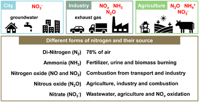
“Planetary boundaries” proposed by Rockström et al. in 2009 define the limits for maintaining the stability of the natural environment and ecosystems of the Earth. They constitute a guideline for evaluating the effects of human activities on the Earth system.1 The “planetary boundaries” include nine items: climate change, loss of biodiversity, land use change, nitrogen and phosphorus cycles and so on. Human society can develop and prosper if activities remain within safe limits. However, if the limits are exceeded, irreversible environmental changes might occur for humanity and for the Earth. In 2023, Richardson et al. reported that six of these nine items had already exceeded their respective danger zones.2The nitrogen cycle represents the most severe of the problems, exceeding the limit by three times or more. Nitrogen, an essential element that maintains the balance of nature, circulates in various forms. For instance, nitrogen exists in the atmosphere as nitrogen molecules, N2, and also exists on Earth in compounds such as ammonia (NH3), nitrous acid (NO2−), nitric acid (NO3−), nitric oxide (NO), and nitrogen dioxide (NO2).3,4 These nitrogen compounds are involved in a myriad of environmental difficulties such as air pollution, water pollution, climate change, stratospheric ozone depletion, eutrophication and acidification (Fig. 1).5,6 In particular, the impacts of human activities on this nitrogen cycle are strongly significant. The following three issues are of crucial importance.
The first is that the amount of ammonia supplied to human society by the Haber–Bosch process is enormous. It is necessary to consider its balance with nature. Of course, the Haber–Bosch process has improved the production of nitrogen fertilisers dramatically. Since the 20th century, it has greatly supported the improvement of agricultural productivity. However, at present, the contribution of natural nitrogen fixation is far outweighed by chemical fertilisers and other artificial sources of fixed nitrogen, which ultimately engender environmental degradation of the soil and hydrosphere.3 Of the nitrogen fertiliser applied to agriculture, the nitrogen not absorbed by crops flows into rivers and the atmosphere, exacerbating a chain reaction of the diffusion of nitrogen compounds. This burden engenders excessive nitrogen loads on soil and water, causing eutrophication and groundwater pollution.
The second is the production of nitrogen oxides (NOx) through fuel combustion with air at high temperatures.7,8 NOx produced by vehicles and industrial activities affects the human body, causing air pollution, acid rain, and harming forest and lake ecosystems. In fact, NOx is known to be produced in three ways: thermal NOx, which is produced by the reaction of nitrogen and oxygen in the air during high-temperature combustion; fuel NOx, which is produced by the oxidation of nitrogen in fuel; and prompt NOx, which is produced when natural gas is burned. Moreover, NOx is known to be emitted from systems of two types: (1) stationary sources such as gas engines, boilers, turbines, and chemical plants; and (2) mobile sources such as car and ship engines. As a NOx reduction technology, the selective catalytic reduction method has been put to practical use for stationary sources. Additionally, the three-way catalyst method has been used for mobile sources such as gasoline-powered cars. To a certain degree, many difficulties have been overcome. Nevertheless, technical issues remain to be solved in relation to reducing and controlling NOx emissions from catalysts in low-temperature environments, such as those encountered with hybrid vehicles.
The third category is emissions of N2O produced by agriculture and sewage treatment and during the denitrification process. Even with the development of technologies for removing NOx and NH3, one nitrogen compound that cannot be completely alleviated completely is N2O. In fact, N2O has a global warming effect about 300 times greater per molecule than carbon dioxide (CO2). In addition to being an ozone-depleting substance, it also has a very long atmospheric lifetime of about 116 years.9 It can be reasonably inferred that the amount of N2O produced from natural sources is more remarkable in quantity than that produced from human sources. Of these, it is thought that the primary sources of anthropogenic emissions are agricultural production and sewage treatment, but N2O is also produced during the denitrification process in the post-treatment stage of high-temperature combustion boilers for fossil fuels and automobile exhaust gas. Concerns have arisen about the impact of N2O on climate change, but N2O reduction technology development is being pursued.
As described above, from the perspective of planetary boundaries, the nitrogen cycle is a fundamentally important environmental issue. To address it and related issues, technological innovation and the introduction of new policies are necessary. Comprehensive efforts at creating a sustainable society must be undertaken. This paper summarises recent NOx and N2O catalytic conversion processes, technologies, and catalyst materials. Furthermore, we introduce our related efforts, specifically in developing electric field-assisted catalytic processes. The catalytic process of applying a direct current electric field to a semi-conductive catalyst is recognized for its ability to function at low temperatures and with high energy efficiency, making it a promising approach in the realm of sustainable catalytic technologies.
2. Nitrogen budget and wastewater treatment
The excessive production of NH3 via the Haber–Bosch process has disrupted the nitrogen balance, leading to an overaccumulation of nitrogen in soils and aquatic systems. The nitrogen budget represents the equilibrium between the inputs and outputs of fixed nitrogen within a system. By calculating each nitrogen flux, the nitrogen budget provides insight into nitrogen pollution and the underlying nitrogen flows contributing to it. Recently, Hayashi and colleagues investigated nitrogen budgets in Japan during 2000–2015, eventually summarising nitrogen emissions to the atmosphere and aquatic environments.10 Their findings indicate that of 5.76 million tons of nitrogen waste in 2010, 1.96 million tons of reactive nitrogen were released into the environment, with 64% emitted to the atmosphere and 36% to water bodies. Additionally, Zhang et al. compiled estimates of global nitrogen reservoirs.11 The largest nitrogen reservoir on the Earth's surface is atmospheric N2 gas (approximately 4 × 10⁹ Tg N), followed by oceanic N2 at 6.6 × 10⁵ Tg N, terrestrial water (lakes, rivers, and groundwater) at 1.0 × 10⁴ Tg N, and soils and coastal sediments at 1.1 × 10⁵ Tg N. A large quantity of the fixed nitrogen in the environment is stored in oceans, with nitrate (NO3−) being the most abundant form. The influx of large amounts of nitrogen compounds into water bodies, such as rivers and oceans, contributes to the eutrophication of marine environments.In response to these circumstances, the conversion of NO3− in industrial and agricultural wastewater,12 adsorption techniques for selective removal of nitrate from water,13 and many techniques for the removal of ammonia nitrogen from wastewater have been developed and investigated. Xiang et al. compared various ammonia–nitrogen wastewater treatment methods: physical (e.g., air stripping, membrane technology), chemical (e.g., struvite precipitation method, electrochemical oxidation and photocatalysis), and biological.14 Among them, methods such as acid adsorption, struvite precipitation, membrane enrichment, microalgae and photosynthetic bacteria can recover ammonia nitrogen with satisfactory efficiency, which is expected to be more beneficial in terms of a circular economy and energy than merely removing it. In the future, based on the current main methods for ammonia–nitrogen recovery, improvements or combinations with other methods are expected to be effective for recovering ammonia nitrogen in more complex wastewater mixtures.
3. The NOx removal catalyst and system
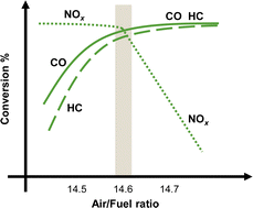
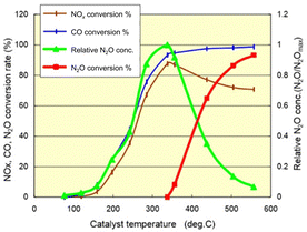
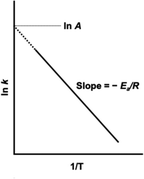
Demonstrably, NOx causes environmental problems such as acid rain and photochemical smog, and poses risks to human health. Automobile exhaust emissions are regarded as one cause of air pollution. Exhaust gas regulations have been implemented.15 The typical composition of exhaust emissions from gasoline engine vehicles under usual driving conditions is the following: carbon monoxide (CO < 0.5 vol%), unburned hydrocarbons (HC < 500 ppmv), nitrogen oxides (NOx < 1000 ppmv), water vapour (H2O: 10 vol%), carbon dioxide (CO2: 10 vol%), and oxygen (O2 > 0.5 vol%).16 Of these gases, HC, CO and NOx are the main harmful pollutants. Purification of these gases is necessary. Currently, a three-way catalyst (TWC) is used to convert CO, HC and NOx respectively into the harmless products of CO2, N2 and H2O to control and suppress the environmental impacts of gasoline vehicle exhaust gas.17,18 The design of a TWC consists of a monolith substrate, an oxygen storage promoter material with a high surface area, an active catalyst (platinum group metals or PGMs), and a promoter material. For the reaction over the TWC, the atmosphere is particularly important. Fig. 2 shows a graph with the air–fuel ratio on the horizontal axis and the purification rate of each component on the vertical axis.18 When the air–fuel ratio is close to the stoichiometric point of approximately 14.6–14.7 (theoretical air–fuel ratio), the TWC functions efficiently. Simultaneous conversion of CO/HC/NOx is achieved. The side with a value smaller than the theoretical air–fuel ratio is called a rich atmosphere. The other side with a value larger than the theoretical air–fuel ratio is called a lean atmosphere.In catalytic reactions, an important factor for exhaust gas purification is the reaction temperature. Fig. 3 shows a graph with the gas temperature at the catalyst inlet (automobile exhaust gas temperature) on the horizontal axis and the purification rate of each component on the vertical axis.19 Ensuring high purification performance requires raising of the catalyst inlet temperature to a certain extent: around 573 K or more. This fact can also be understood from the Arrhenius equation presented in Fig. 4. The Arrhenius equation is expressed as ln![[thin space (1/6-em)]](https://www.rsc.org/images/entities/char_2009.gif) k = ln
k = ln![[thin space (1/6-em)]](https://www.rsc.org/images/entities/char_2009.gif) A − Ea/RT, where A denotes the frequency factor and Ea stands for the apparent activation energy. It has been proven by experimentation that plotting ln
A − Ea/RT, where A denotes the frequency factor and Ea stands for the apparent activation energy. It has been proven by experimentation that plotting ln![[thin space (1/6-em)]](https://www.rsc.org/images/entities/char_2009.gif) k against 1/T for many reactions produces a straight line, and that the reaction rate increases as the temperature rises. Based on the Arrhenius law, it is considered difficult to lower the temperature of the reaction. However, to overcome this challenge, research and development of catalytic processes for lowering the temperature have been progressing in recent years. Here, we categorise recent research trends into three categories: (1) the development of catalyst materials to lower the activation energy of reactions, (2) the development of processes to increase the reactant concentration for increasing reaction rates, and (3) the development of processes to increase the reaction rate constant by introducing external force fields.
k against 1/T for many reactions produces a straight line, and that the reaction rate increases as the temperature rises. Based on the Arrhenius law, it is considered difficult to lower the temperature of the reaction. However, to overcome this challenge, research and development of catalytic processes for lowering the temperature have been progressing in recent years. Here, we categorise recent research trends into three categories: (1) the development of catalyst materials to lower the activation energy of reactions, (2) the development of processes to increase the reactant concentration for increasing reaction rates, and (3) the development of processes to increase the reaction rate constant by introducing external force fields.
3.1. Development and design of new catalysts for NOx removal
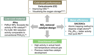
As shown by the apparent activation energy Ea given by the slope of the ln![[thin space (1/6-em)]](https://www.rsc.org/images/entities/char_2009.gif) k vs. 1/T plot, a smaller apparent activation energy is associated directly with less temperature dependence of the rate constant. The catalyst can show high activity even at low temperatures. Herein, we summarise recent research on improving low-temperature activity and the current state of new catalyst material development (Fig. 5).
k vs. 1/T plot, a smaller apparent activation energy is associated directly with less temperature dependence of the rate constant. The catalyst can show high activity even at low temperatures. Herein, we summarise recent research on improving low-temperature activity and the current state of new catalyst material development (Fig. 5).
Rood et al. reviewed the low-temperature activation performance of three-way catalysts, noting that an important shortcoming of modern TWC designs is the cold-start performance achieved during the first few minutes of vehicle operation.17 In particular, they explained the composition of the TWC and summarised the temperature (T50) at which the conversion rate for CO, HC and NOx conversion is 50%. The three-way catalysts used widely in gasoline vehicles maintain high purification rates even when the air–fuel ratio deviates from the stoichiometric ratio, such as in situations where the air–fuel ratio changes transiently, because of the adsorption and release of oxygen by the oxygen storage material. Ceria-zirconia (CZ) is added to the TWC to improve the oxygen storage capacity (OSC). Usually, CZ materials containing 40–60% ceria are used because of their high OSC. In recent years, research has also been conducted to elucidate the complex oxygen storage mechanism to improve catalyst performance and to suppress degradation. Nagasawa et al. and You et al. have visualised the distribution of oxygen storage in a model three-way catalyst using a method that combines isotope labelling and high-temperature reaction quenching using isotopes to elucidate and model the oxygen adsorption and desorption mechanism.20,21 Their findings showed that the presence of Pd increases the surface oxygen concentration and the depth of diffusion into the CZ bulk, and showed that the Pd/CZ interface is more likely to adsorb oxygen than the Pd surface. Furthermore, when the oxygen transport behaviour in the bulk region was investigated, findings indicated that the bond strength between oxygen and surrounding atoms was weakened by Zr doping, making it easier to form oxygen vacancies and to migrate oxygen ions. In conventional ternary catalyst materials, the use of precious metals such as Rh is an important option for lowering the apparent activation energy. However, because the cost of Rh is particularly high, a low-Rh catalyst material design must be introduced.17 The use of alloys and new catalyst designs such as single-atom catalysts (SAC), have the potential to reduce Rh loading for enhancing the performance at low temperatures.
Regarding alloy catalysts, Sato et al. found that alloy nanoparticles, which are a homogeneous mixture of Pd and Ru, which do not normally mix, show catalytic activity surpassing that of Rh.22 They also clarified that the reason for this high activity is that the alloy nanoparticles have electronic characteristics similar to those of Rh, and that they can be characterised as “pseudo-Rh”. They found that NOx, which was difficult to purify at low temperatures using catalysts other than Rh, was removed efficiently on Pd–Ru-nanoparticles. Moreover, they demonstrated that the catalyst showed extremely high catalytic performance at temperatures below 473 K, equivalent to Rh or even surpassing that of Rh. The catalyst was also found to have very high catalytic performance even for the removal of CO and C3H6. However, the difficulty with this Pd–Ru nanoalloy was that its structure would collapse during the exhaust gas purification reaction at high temperatures, causing a loss of activity. Therefore, by adding a third element to this Pd–Ru, the arrangement entropy was increased. Moreover, various nanoalloys were developed that stabilised the solid solution structure at high temperatures.23 It was discovered that Pd–Ru–iridium (Ir) nanoalloys were more active and more durable than either Pd–Ru or Rh. They also maintained excellent catalytic activity even after 20 cycles, with no apparent degradation in 1000 ppm NO, 6000 ppm CO, 555 ppm C3H6, 6000 ppm O2, 2000 ppm H2, and 13.9% CO2, SV: 60![[thin space (1/6-em)]](https://www.rsc.org/images/entities/char_2009.gif) 000 h−1. In the case of PdRuIr, the cost of the raw materials is about one-tenth that of Rh. This discovery is expected to have a decisive effect on the Rh-dependent automotive exhaust purification industry and to contribute to the development of new types of TWC that meet stricter emission regulations.
000 h−1. In the case of PdRuIr, the cost of the raw materials is about one-tenth that of Rh. This discovery is expected to have a decisive effect on the Rh-dependent automotive exhaust purification industry and to contribute to the development of new types of TWC that meet stricter emission regulations.
In addition, SAC is being developed as a new catalyst design. SAC uses a single atom as a catalytic active site. Therefore, the efficiency of using precious metals is extremely high.24 This extremely high efficiency allows high catalytic activity with TWC using a small amount of precious metal.25 Recently, Khivantsev's group used the atomic trapping method to disperse single atoms of Rh, Ru, Pd, Pt, or Ir on CeO2.26–28 The activity for the low-temperature NO + CO reaction is in the order of Rh > Pd ≈ Ru > Pt > Ir.26 They also showed that Rh(I) monomers are remarkably active and selective at removing NO from wet industrial TWCs at 393 K.27 Furthermore, they developed a catalyst with Ru1O5 sites (five oxygen atoms are coordinated to one Ru) dispersed at the atomic level on the (100) surface of ceria using the same method.28 The catalyst shows excellent activity in the NO oxidation reaction: an essential step in the NSR process (the next chapter presents NSR process details). Actually, Ru1/CeO2 showed very high NOx storage properties by virtue of the formation of stable Ru–NO complexes and a high NOx spillover rate to CeO2. The Ru content required for excellent NOx storage is only about 0.05 wt%. To promote the catalytic performance of conventional SACs further, a dual-site strategy that functions by arranging two atoms in adjacent positions has been developed recently. Tan et al. prepared homogeneous PdxRh1−x solid solutions as dual-atom-site catalysts (DACs).29 The Rh–Pd dual atom sites of Pd0.1Rh0.9 and Pd0.3Rh0.7 activated CO and NO in a TWC reaction, showing better activity than that of pure Rh. Zhou et al. immobilised Pt and Pd double atoms on a CeO2 support (Pt–Pd SAC).30 The synergistic effect between adjacent Pt and Pd atoms is that they function separately as active sites for CO and NO adsorption. The Pt–Pd structure promotes the migration of active intermediates effectively and accelerates the reaction rate.
Although many materials are being developed as described above, their activity at low temperatures in actual exhaust gas environments (where oxygen and water vapour are present) remains low. In addition, despite the potential for reducing the use of precious metals using alloy catalysts, SACs, and DACs, the use of precious metals is still the mainstream today. Efforts to develop precious metal-free catalysts must be pursued.31
3.2. NOx storage reduction (NSR) catalysts
Many reactions follow the rate equation r = k[A]a[B]b…. The reaction rate is proportional to the rate constant and to the concentration of reactants. One option for increasing the reactants’ concentration is the lean NOx trap catalyst. Lean-burn gasoline engines have attracted attention recently because they emit less CO2 and have better fuel efficiency than that of conventional gasoline engines.32–34 However, because of the large amounts of oxygen in exhaust gases in the cases of excessive lean combustion, conventional three-way catalysts are ineffective at reducing NOx. The NOx storage reduction (NSR) method, reported by Toyota Motor Corp., is a leading technology for controlling NOx emissions under lean combustion conditions.35 The NSR catalyst adsorbs the NOx produced by the lean combustion. Fuel is injected at once to create a rich condition. Then the adsorbed species are simultaneously reduced and removed. In the lean atmosphere, NO is oxidised to NO2 on the precious metal (mainly Pt); then it is stored in the form of nitrates on the surface of alkaline earth oxide (mostly Ba). In the subsequent rich environment, the stored NOx is reduced to N2 on the precious metal, thereby regenerating the catalyst.36–38 The readily apparent source of reductants (H2, CO and HC) is the onboard fuel in lean-burn gasoline engines, but the efficiency of NOx reduction varies depending on the reductant which is used.36 In fact, H2 is the most effective for NOx reduction and catalyst surface regeneration. In contrast, CO and C3H6 are less effective as reductants at low operating temperatures; also, C3H8 shows no NOx reduction ability for stored NOx.39 Next, we specifically examine the NSR process using H2. Several studies have specifically assessed the reduction mechanism of stored NOx by H2. One mechanism is called reverse NOx spillover, by which NOx stored as nitrates reportedly spills over to the Pt site. Then NO and N2 are released by the reductant.40–43 Other proposed mechanisms include the activation of H2 on Pt sites and subsequent hydrogen spillover to adsorbed nitrate.40,41,44,45 However, the NSR process requires frequent injection of rich spikes. The consequent deterioration in fuel efficiency is unavoidable.46,47In the NSR process, the selectivity of the products toward N2 or NH3 can be influenced by the air–fuel ratio during rich spikes.48 To optimise this feature, a synergistic combination of NSR and selective catalytic reduction (SCR) technologies has been developed.48–51 The NH3 generated by NSR can serve as a reductant in the SCR catalyst, thereby improving the NOx removal efficiency.48 Traditionally, AdBlue® is used commercially as a reductant in SCR systems, but combining NSR with SCR reduces ammonia consumption and lowers PGM usage.49,50 Onrubia-Calvo et al. summarise a comparison of stand-alone NSR, stand-alone SCR, sequential NSR–SCR, and dual layer NSR–SCR technologies for NOx removal in diesel light-duty vehicles.52 Although the combination of these technologies is important for reducing exhaust gas during cold start and for reducing other components (NOx, NH3, N2O, etc.), its system complexity and high power consumption are expected to create challenges for this development.
3.3. Synergistic catalytic processes for NOx conversion
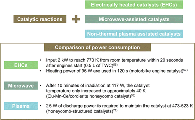
The use of external force fields in catalytic processes has been proposed to increase reaction rate constants. Specifically, electrically heated catalysts (EHCs), microwave-assisted catalysts, and non-equilibrium plasma-assisted catalysts have been proposed. EHCs can heat the catalyst electrically and activate it from low temperatures, even during cold starts when the temperature is low and the catalytic activity is not fully functioning.53–55 EHC uses a metal honeycomb as the catalyst substrate. By applying electricity through the structure, the catalyst itself is heated. Consequently, the temperature rises quickly to the operating temperature. Furthermore, the temperature distribution in the radial direction is uniform. Stable catalytic performance can be achieved. In actuality, EHC is a promising solution for reducing emissions during cold engine start-up by virtue of its flexibility in temperature control. Moreover, it is highly convenient for application to hybrid electric vehicles (HEVs).53 However, it is necessary to input as much as 2 kW of power to reach 773 K from room temperature within 20 s after engine start.56 Even in motorcycle engines, EHC devices with a heating power of 96 W are used to reach the working temperature in 120 s.57 In fact, EHCs have high power consumption, leading to issues such as higher costs, increased weight, improved mounting performance, and the need for larger generators, and additional batteries. Therefore, many shortcomings persist in practical terms.Microwave-assisted catalytic reactions have attracted much attention because they markedly improve the rate and selectivity of catalytic reactions under mild conditions.58–60 Microwaves are extremely high-frequency electromagnetic waves between radio waves and infrared rays. They therefore have a selective effect on polar molecules. Evaluations of the direct decomposition of NO using microwaves have been conducted. Direct decomposition of NO requires a certain power output to maintain a high reaction temperature. In the past, direct decomposition of NO using microwaves required continuous energy output of approximately 300 W:61 energy consumption is high when treating low-concentration exhaust gas at high flow rates. Yu et al. investigated the decomposition of NO into N2 and O2 by first adsorbing NO using an adsorbent and by then irradiating it with microwaves.59 A new, inexpensive adsorbent with a high adsorption capacity, MgCo2O4–BaCO3/active carbon composite, was developed.60 Most of the NO was adsorbed chemically onto the active sites of MgCo2O4 and BaCO3. Some of it was adsorbed physically onto the active carbon. Subsequently, the adsorbed NO was decomposed into N2 and O2 under microwave irradiation. Actually, O2, which is a non-polar molecule, is not activated by low-temperature microwave electromagnetic fields. Therefore, almost no formation of NO2 occurred through reactions between coexisting O2 and NO. These studies demonstrate the potential for a new, highly efficient, low-energy-consumption method by combining adsorption and microwaves. However, even for these studies, up to 300 W of energy was necessary to decompose NO. Moreover, consideration of the microwave irradiation of honeycomb catalysts for practical automotive applications presents challenges in the effective use of microwaves. Current research investigating the combination of direct NO decomposition and microwave irradiation remains largely in the laboratory stage, mostly using catalysts that are in powder form.62 Herein, we highlight an example in which, instead of direct NO decomposition, the catalytic oxidation of gaseous toluene was achieved using a Cu–Mn–Ce/cordierite honeycomb catalyst under microwave heating. After 10 min of irradiation at 117 W, the catalyst temperature increased only to approximately 40 K.63 This limited temperature increase is attributed to the low microwave absorption capacity of the honeycomb substrate. In powder materials, microwaves generate heat uniformly throughout their volume, thereby minimising processing time, reducing power consumption, and improving diffusion rates. All represent important benefits.64 Those benefits notwithstanding, because of the low energy efficiency of microwave-assisted processes in monolithic supports, the path to practical implementation remains challenging.
Plasma research is attracting attention as a technical solution to the low-temperature activity of catalysts.65 Plasma is a partially or fully ionised gas comprising various particles such as electrons, ions, atoms, and molecules. In non-thermal plasma (NTP), the temperature is not in the thermal equilibrium; it differs greatly between electrons and other particles (ions, atoms and molecules). In this sense, NTP is also called “non-equilibrium plasma” or “cold plasma”. Because of their small mass, electrons can be accelerated easily by an electric field. The electron temperature in the NTP is usually between 10![[thin space (1/6-em)]](https://www.rsc.org/images/entities/char_2009.gif) 000 K and 250
000 K and 250![[thin space (1/6-em)]](https://www.rsc.org/images/entities/char_2009.gif) 000 K (1–20 eV). Gholami et al. outlined a combination of NTP and catalytic systems as an alternative technology for removing NOx from stationary and mobile emission sources in lean-burn combustion.66 Plasma catalytic systems are applied mostly at low temperatures (below 573 K), at which current thermal activation techniques are inefficient. In general, NTP engenders the formation of oxygenated species such as aldehydes and nitrogen-containing organic species. Also, NO is converted to NO2, improving the NOx removal rate in HC-SCR and NH3-SCR reactions. Shi et al. developed non-thermal plasma-assisted NOx storage and reduction.67–70 Using H2 plasma to regenerate NSR catalysts improved NOx conversion, especially in the low-temperature range: 423 K and above. However, inhibition caused by adding H2O and CO2 in the feed gas was observed in most of the studied catalysts. Furthermore, the hydrogen required for this H2 plasma is supplied from the fuel itself. However, providing 1–3% H2 through rich spikes can lead to reduced fuel efficiency. Consequently, numerous researchers have examined NOx removal using plasma-catalytic systems, showing various synergistic effects. Nonetheless, no report describes the demonstration of the use of such systems in vehicles,66 likely because of practical challenges in combining plasma technology with honeycomb-structured catalysts.71 Dielectric barrier discharge (DBD) plasma systems, which can generate NTP, require a discharge gap of several millimetres. This limitation poses issues such as pressure drop and low mechanical resistance, making high-throughput gas processing impractical. By contrast, honeycomb-structured catalysts, with their matrix of narrow channels, are known for lower pressure drop and high mechanical stability, marking them as promising alternatives. Nonetheless, the plasma discharge length is typically limited to a few centimetres, thereby restricting the gas volume, which can be processed and preventing sufficient chemical reactions on the catalyst, leading to incomplete removal of harmful substances from the exhaust. Nguyen et al. also conducted experiments on the SCR of NOx using honeycomb plasma discharge.71 The feed gas consisted of 100 ppm NO and 86 ppm n-heptane, with a 60 L min−1 total flow rate and fixed water content of 2.4%. Plasma-assisted catalytic reactions require 25 W of discharge power, corresponding to a specific energy input of 25 J L−1 (SEI, energy density), to achieve 50% NO to NO2 conversion at 473 K. Under these conditions, no removal or reduction of NOx by the plasma discharge/honeycomb catalyst occurs: only oxidation of NO to NO2. Although the energy consumption is lower than EHC or microwave-assisted catalytic reactions, it is impractical for assisting actual high throughput gas flow rates. Many challenges persist, hindering the practical application of plasma catalytic systems in vehicles using honeycomb catalysts.
000 K (1–20 eV). Gholami et al. outlined a combination of NTP and catalytic systems as an alternative technology for removing NOx from stationary and mobile emission sources in lean-burn combustion.66 Plasma catalytic systems are applied mostly at low temperatures (below 573 K), at which current thermal activation techniques are inefficient. In general, NTP engenders the formation of oxygenated species such as aldehydes and nitrogen-containing organic species. Also, NO is converted to NO2, improving the NOx removal rate in HC-SCR and NH3-SCR reactions. Shi et al. developed non-thermal plasma-assisted NOx storage and reduction.67–70 Using H2 plasma to regenerate NSR catalysts improved NOx conversion, especially in the low-temperature range: 423 K and above. However, inhibition caused by adding H2O and CO2 in the feed gas was observed in most of the studied catalysts. Furthermore, the hydrogen required for this H2 plasma is supplied from the fuel itself. However, providing 1–3% H2 through rich spikes can lead to reduced fuel efficiency. Consequently, numerous researchers have examined NOx removal using plasma-catalytic systems, showing various synergistic effects. Nonetheless, no report describes the demonstration of the use of such systems in vehicles,66 likely because of practical challenges in combining plasma technology with honeycomb-structured catalysts.71 Dielectric barrier discharge (DBD) plasma systems, which can generate NTP, require a discharge gap of several millimetres. This limitation poses issues such as pressure drop and low mechanical resistance, making high-throughput gas processing impractical. By contrast, honeycomb-structured catalysts, with their matrix of narrow channels, are known for lower pressure drop and high mechanical stability, marking them as promising alternatives. Nonetheless, the plasma discharge length is typically limited to a few centimetres, thereby restricting the gas volume, which can be processed and preventing sufficient chemical reactions on the catalyst, leading to incomplete removal of harmful substances from the exhaust. Nguyen et al. also conducted experiments on the SCR of NOx using honeycomb plasma discharge.71 The feed gas consisted of 100 ppm NO and 86 ppm n-heptane, with a 60 L min−1 total flow rate and fixed water content of 2.4%. Plasma-assisted catalytic reactions require 25 W of discharge power, corresponding to a specific energy input of 25 J L−1 (SEI, energy density), to achieve 50% NO to NO2 conversion at 473 K. Under these conditions, no removal or reduction of NOx by the plasma discharge/honeycomb catalyst occurs: only oxidation of NO to NO2. Although the energy consumption is lower than EHC or microwave-assisted catalytic reactions, it is impractical for assisting actual high throughput gas flow rates. Many challenges persist, hindering the practical application of plasma catalytic systems in vehicles using honeycomb catalysts.
Fig. 6 presents a summary of the power consumption necessary for EHCs, microwave irradiation, and plasma in catalytic reactions.
3.4. Electric field-assisted three-way catalysis
Although EHC, plasma and microwave assistance constitute important technical solutions for the low-temperature activity of catalysts, they yet require large amounts of electrical energy. That energy presents important challenges for maintaining stable catalytic reactions.In contrast, the catalytic process of applying a direct current electric field to a semi-conductive catalyst is known to be able to operate at low temperatures and to be energy efficient.72–74 Various applications to different reactions have been investigated. Applying an electric field to the catalytic process of NOx conversion is also very attractive.
Reportedly, a Pd catalyst (Pd/Ce0.7Zr0.3O2) in an electric field shows extremely high three-way catalytic activity (TWC: NO–C3H6–CO–O2–H2O).75,76 When an electric field is applied, the conversions of NO, C3H6 and CO and the N2 selectivity are extremely high, even with coexisting O2 and H2O and even at low temperatures (423–473 K), as presented in Fig. 7. The NO conversion and N2 selectivity were 54.9% and 91.3% respectively, in the presence of an electric field at 428 K. NO conversion reaches 100% at 517 K. In contrast, in the absence of an electric field, the NO conversion rate and N2 selectivity are very low (almost 0%) in the low-temperature range. For these tests, the catalyst layer temperature was measured directly using a thermocouple attached to the catalyst. The Joule heat effect from the applied direct current on the catalytic activity was confirmed. As a result, it was possible to state that the high activity/selectivity was not attributable to Joule heat. Furthermore, the power consumption for applying the current was only 1.2 W at 428 K in this case. Therefore, catalysis in the electric field enables a highly efficient three-way catalytic system at much lower temperatures than those used for conventional systems. This promotion effect of the electric field differs entirely to that of EHC or plasma reactions introduced in the preceding section. To verify whether plasma effects can be neglected in this system, a plasma reaction was conducted using the same TWC gas composition. At 375 K and 468 K, the respective NO conversion rates achieved by plasma were only 5.6% and 7.4%. These values are markedly lower than the catalytic activity under an electric field shown in Table 1. Consequently, the promotion effect of the electric field on the TWC reaction is considerably greater than that of plasma reactions. The contribution of reducing agents (C3H6 and CO) to catalytic NO reduction at low temperatures in the electric field was investigated. Fig. 8 shows the NO conversion rate with and without an electric field in the low-temperature range (420–500 K catalyst layer temperature). In the NO–CO–O2–H2O conditions, the NO conversion rate was almost 100%, irrespective of the presence or absence of an electric field. No significant difference was found in the NO conversion rate. In contrast, in the NO–C3H6–O2–H2O conditions, a clear difference was found in the NO conversion rate with or without an electric field at 420–500 K. Furthermore, the NO conversion rate and N2 selectivity achieved when an electric field was applied under the NO–C3H6–O2–H2O conditions were almost identical as a result of the TWC conditions. These results suggest that the NO–C3H6 reaction is dominant under the TWC conditions with an electric field at low temperatures (420–500 K). To clarify the effects of coexisting O2 on the TWC reaction, we conducted O2 partial pressure dependence tests under both NO–CO–O2–H2O and NO–C3H6–O2–H2O conditions with and without an electric field. Under the NO–CO–O2–H2O conditions, the conversion rate behaviours of the NO, CO, and O2 in response to changes in O2 concentration were the same with and without an electric field. The NO conversion rate decreased and the CO conversion rate increased concomitantly with increasing O2 concentration. These trends suggest that CO was consumed by the CO–O2 reaction rather than by the NO–CO reaction. These findings indicate that the electric field does not contribute to the NO–CO and CO–O2 reactions in the low-temperature region (420–500 K). In contrast, under NO–C3H6–O2–H2O conditions, a drastic difference was found in the dependence of the NO reaction rate on the O2 concentration with and without an electric field. In the absence of an electric field, the NO reaction rate shows negative dependence on the O2 concentration. However, under electric field conditions, the NO reaction rate is positively correlated with the O2 concentration at 0–1000 ppm. The NO reaction rate decreases considerably at O2 concentrations of 1000–1500 ppm because O2 causes excessive adsorption on the Pd metal, the active site of the NO–C3H6 reaction. By contrast, O2 positively affects the NO–C3H6 reaction at 0–1000 ppm O2. Reportedly, NOx is reduced by hydrocarbons according to eqn (1)–(4).77 The partially oxidised species of hydrocarbons (CxHyOz) are known to be important intermediates in HC-SCR.78
| NO(g) + O2(g) → NOx(ads) | (1) |
| CxHy(g) + O2(g) → CxHyOz(ads) | (2) |
| NOx(ads) + CxHyOz(ads) → R–NCO(ads) | (3) |
| NOx(ads) + R–NCO(ads) → N2(g) + CO2(g) | (4) |
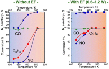 | ||
Fig. 7 NO, CO and C3H6 conversion and N2 selectivity over 0.5 wt% Pd/Ce0.7Zr0.3O2 under NO–C3H6–CO–O2–H2O reaction: NO, 2500 ppm; C3H6, 500 ppm; CO, 3000 ppm; O2, 2500 ppm; H2O, 70![[thin space (1/6-em)]](https://www.rsc.org/images/entities/char_2009.gif) 000 ppm; Ar balance; SV, 72 000 ppm; Ar balance; SV, 72![[thin space (1/6-em)]](https://www.rsc.org/images/entities/char_2009.gif) 000 h−1, applying 1.5 mA direct current. Reproduced from ref. 75 with permission from RSC Publishing, copyright 2021. 000 h−1, applying 1.5 mA direct current. Reproduced from ref. 75 with permission from RSC Publishing, copyright 2021. | ||
| NO conversion/% | |||
|---|---|---|---|
| Plasma reaction | 5.6 (at 375 K) | 7.4 (at 468 K) | |
| NO decomposition in the electric field | 2.7 (at 451 K) | 2.3 (at 532 K) | 2.5 (at 625 K) |
| Heated catalytic reaction | 0.0 (at 420 K) | 0.3 (at 449 K) | 0.26 (at 478 K) |
| Electric field reaction with reductants (3 mA) | 19.1 (at 414 K) | 16.5 (at 433 K) | 20.5 (at 457 K) |
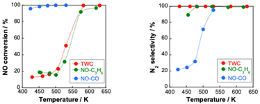 | ||
Fig. 8 NO conversion and N2 selectivity over 0.5 wt% Pd/Ce0.7Zr0.3O2 under NO–C3H6–CO–O2–H2O reaction (NO, 2500 ppm; C3H6, 500 ppm; CO, 3000 ppm; O2, 2500 ppm; H2O, 70![[thin space (1/6-em)]](https://www.rsc.org/images/entities/char_2009.gif) 000 ppm Ar balance; 200 cc min−1 total flow); NO–CO–O2–H2O reaction (NO, 2500 ppm; CO, 3000 ppm; O2, 250 ppm; H2O, 70 000 ppm Ar balance; 200 cc min−1 total flow); NO–CO–O2–H2O reaction (NO, 2500 ppm; CO, 3000 ppm; O2, 250 ppm; H2O, 70![[thin space (1/6-em)]](https://www.rsc.org/images/entities/char_2009.gif) 000 ppm Ar balance; 200 cc min−1 total flow) and NO–C3H6–O2–H2O reaction (NO, 2500 ppm; C3H6, 500 ppm; O2, 2500 ppm; H2O, 70 000 ppm Ar balance; 200 cc min−1 total flow) and NO–C3H6–O2–H2O reaction (NO, 2500 ppm; C3H6, 500 ppm; O2, 2500 ppm; H2O, 70![[thin space (1/6-em)]](https://www.rsc.org/images/entities/char_2009.gif) 000 ppm Ar balance; 200 cc min−1 total flow) with and without an electric field at 3 mA (denoted as EF); reproduced from ref. 75 with permission from RSC Publishing, copyright 2021. 000 ppm Ar balance; 200 cc min−1 total flow) with and without an electric field at 3 mA (denoted as EF); reproduced from ref. 75 with permission from RSC Publishing, copyright 2021. | ||
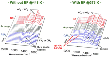 | ||
| Fig. 9 DRIFT spectra of Pd/Ce0.7Zr0.3O2 during the transient test, switching from C3H6 to NO flow. Reproduced from ref. 76 with permission from RSC Publishing, copyright 2022. | ||
3.5. Electric field-assisted NSR process for lean NOx reduction
Although NSR systems have been developed to purify exhaust gases from lean-burn engines, such systems require periodic operation, which adversely affects fuel efficiency.46,47 As a novel approach to this difficulty, catalysis in an electric field was proposed for lean NOx reduction.79 This new NSR process uses H2 in a lean atmosphere to reduce stored NOx without switching to rich combustion after NOx storage, thereby improving engine efficiency. Lean NOx reduction tests were conducted with and without an electric field using a 3 wt% Pt–16 wt% BaO/CeO catalyst. Total flow of 200 cc min−1 of 0.2 vol% H2, 8 vol% O2 and 10 vol% H2O was supplied. The stored NOx was reduced at 423 K for 1 h. The results are presented in Fig. 10. In the absence of an electric field, the conversion rate from NOx to N2 was only 2.9%. By contrast, when a 6 mA electric field was applied, a high conversion rate of 13.1% was obtained even under lean conditions at the low temperature of 423 K. The conversion of adsorbed NOx to N2 increased linearly over time. This reaction behaviour remained almost unchanged even when the time of electric field application was doubled. The conversion rate more than doubled: from 13.1% to 29.1%. Observation of surface-adsorbed species by in situ transmission infrared spectroscopy (TIRS) measurements confirmed that more nitrate species were removed from the surface when an electric field was applied in a lean atmosphere. The breakdown of the H2 consumption during the reduction of NOx adsorbed onto the Ba site to N2 and NO was calculated from the stoichiometric ratios of H2, N2, and NO.80–82 The findings indicate that the total consumption of H2 used to produce N2 and NO in the electric field was 0.102 mmol, which is almost equal to the extra H2 consumed during the application of the electric field (0.107 mmol). These findings suggest that the 3 wt% Pt–16 wt% BaO/CeO2 catalyst can convert the adsorbed NOx to N2 using H2, even in a lean atmosphere, by application of an electric field. The important role of the electric field in NOx reduction is to promote the activation and migration of hydrogen species. Earlier studies have demonstrated that applying an electric field to the reaction promotes hydrogen migration on the surface of the support.74,83–85 In heterogeneous catalysts under the electric field, the proton conductivity on the catalyst surface plays an important role: it provides a reaction pathway by collision between H+ on the catalyst support and adsorbed substances on the supported metal.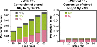 | ||
| Fig. 10 Conversion of stored NOx to N2, and the distribution of nitrogen-containing species in the outlet gas, calculated as nitrogen-based. Reproduced from ref. 79 with permission from RSC Publishing, copyright 2024. | ||
To elucidate the promotion of hydrogen migration by the application of the electric field, lean NOx reduction tests were conducted using a physical mixture of 3 wt% Pt/CeO2 and 16 wt% Ba(NO3)2/CeO2 catalysts. In this physical mixture catalyst, Pt and Ba(NO3)2, which is pre-loaded with nitrate, are present separately. The results demonstrated that nitrate decomposition occurs not only near Pt but also at locations distant from Pt during the application of the electric field. In the lean NOx reduction in the electric field, NOx reduction proceeded only slightly without hydrogen, indicating that NOx reduction results from hydrogen migration because of the electric field application. Furthermore, to assess the role of Pt for hydrogen migration, NOx reduction tests were conducted using only the 16 wt% Ba(NO3)2/CeO2 catalyst without Pt in an electric field. The amount of reduced NOx decreased without Pt, indicating that Pt is necessary for hydrogen migration in an electric field. Therefore, hydrogen migrates from the Pt site to the adsorbed nitrate during lean NOx reduction and reacts with the nitrate directly. Finally, based on the conventional mechanism of H2-induced NSR reactions (Section 3.2 presents related details), the EF-assisted NSR mechanism can be characterised as follows: during lean NOx reduction, hydrogen is migrated from the Pt site to the Ba(NO3)2; it then reacts with the nitrate directly. The released NOx reaches the Pt site, where the NOx is reduced to form N2 (Fig. 11). This proposed EF-assisted NSR process can reduce stored NOx under excess oxygen conditions and at low temperatures. However, it currently has limitations attributable to insufficient activity and extended reduction times (e.g., even after one hour of reduction, NOx conversion at 423 K remains at 13.1%). To overcome these shortcomings, it will be necessary to design catalysts with closer Pt and BaO contact and to optimise the applied current. For future applications, this innovative method is expected to use surplus vehicle power to purify exhaust gas, promote hydrogen transfer, and improve NOx reduction, even at low temperatures (Fig. 12).
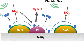 | ||
| Fig. 11 Assumed reaction model for electric field-assisted lean NOx reduction over 3 wt% Pt–16 wt% BaO/CeO2. Reproduced from ref. 79 with permission from RSC Publishing, copyright 2024. | ||
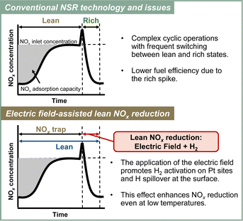 | ||
| Fig. 12 Conceptual diagram of the electric field-assisted catalytic process approach to the issues of conventional NSR technology. | ||
4. N2O removal
During both nitrification and denitrification processes, N2O is produced by various microorganisms through the oxidation and reduction of nitrogen. Mainly, N2O of natural origin is produced during the processes of nitrification and denitrification occurring in the oceans and soil. The main sources of anthropogenic N2O emissions are agriculture, engine exhaust gas, and emissions from nitric acid plants.9,86 The most suitable post-treatment technologies used for N2O reduction are direct catalytic cracking and selective catalytic reduction (SCR).86–88 Direct decomposition is the most efficient, cost-effective and environmentally friendly method for reducing N2O emissions. It is a process by which N2O is decomposed directly into non-toxic and harmless N2 and O2 on a catalyst, creating no secondary pollution. The reaction temperature can be lower than that of pyrolysis.86 The widely accepted model for the reaction mechanism of direct catalytic decomposition of N2O consists of the following three basic reaction equations.89–92| N2O + * → N2(g) + O* | (5) |
| O* + O* ↔ O2(g) + 2* | (6) |
| N2O + O* → N2(g) + O2(g) + * | (7) |
4.1. Synergistic catalytic processes of N2O removal
Wu et al. outlined N2O conversion technologies systematically using not only conventional thermal catalysis, but also light, electricity, and non-catalytic methods. Improvement of N2O decomposition performance by coupling technologies such as plasma synergistic catalysis and microwave-assisted catalysis has been demonstrated.88 In addition, Vadikkeettil et al. introduced the salient benefits of plasma–catalyst hybrid methods, which are applied widely to N2O decomposition, including the abilities to initiate chemical reactions at low temperatures and to improve selectivity.101 In most cases, a single-stage plasma catalytic reactor is used, in which the catalyst pellets are in direct contact with the alternating current (AC)-driven plasma.102,103 The synergistic effect of NTP (non-thermal plasma) on N2O catalytic decomposition with hydroxyapatite (HAP)-supported Rh and Fe catalysts was studied by Tan et al.102 When NTP is applied, the N2O conversion rate of RhFe/HAP-11 at 473 K increases considerably from 7.1% to 90.0%. This improvement is attributable to the involvement of free radicals in the discharge process, and to the longer lifetime of active species, even at high temperatures. The reaction using NTP technology alone requires great amounts of energy. For example, the denitrification efficiency is only 46.6% at an output power of 2 kW. By contrast, NTP combined with RhFe/HAP catalysts can achieve denitrification efficiency of 90% for 10 vol% N2O using plasma output energy of only 4 W and a reaction temperature of 473 K. Jo et al. and Ko et al. have reported γ-Al2O3 as effective for N2O decomposition using the plasma catalytic process.103,104 Among the metals investigated (Ru, Co, Cu, V, etc.), Ru was found to be the most suitable catalyst for N2O decomposition in the plasma catalytic reactor.103 In the absence of plasma, the decomposition efficiency decreased considerably from 59% to 9% as the oxygen content was changed from 0% to 20%. Similarly, the plasma–catalyst decomposition efficiency decreased concomitantly with increasing O2 content, but the degree of decrease was not as pronounced as in the case of using the catalyst alone (from 90% to about 65%). In addition, Li et al. summarised the N2O decomposition mechanism.104Microwave-assisted N2O decomposition was investigated using an alumina-modified nickel–cobalt-based SiC (NiCoAl/SiC).105 For this study, research was conducted of high concentrations of N2O (20 vol%–50 vol% N2O) to mimic the typical composition of the downstream from an adipic acid production plant. The results clarified that the microwave-assisted process removed N2O completely from the high-concentration stream (50 vol%) at 823 K. In actuality, this is the same temperature necessary to remove N2O from a low-concentration gas stream (20 vol%) using conventional heating processes. Microwave heating technology allows selective heating of the catalyst. The heat flux is directed from the inside to the outside of the catalyst bed, which is the opposite of conventional heating, thereby minimising energy losses and creating a more uniform temperature profile within the catalyst bed. As a result, better catalyst performance and shorter processing times can be achieved.106 Furthermore, because microwave heating is an electricity-based technology, some room remains for the electrification of industrial processes, which is thought to enhance environmental sustainability.
4.2. Catalytic N2O decomposition in the presence of O2 with an electric field
We have developed a process combining an electric field catalytic process with N2O decomposition reactions, which establishes an N2O direct decomposition cycle at low temperatures.107 Results have shown that applying an electric field to a 0.5 wt% Rh/Ce0.7Zr0.3O2 catalyst enables efficient decomposition of N2O, even at low temperatures and in the presence of excess oxygen and water vapour (Fig. 13).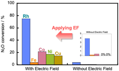 | ||
Fig. 13 Catalytic decomposition of N2O over 0.5 wt% Rh/Ce0.7Zr0.3O2 and 5 wt% Fe, Co, Ni, Cu/Ce0.7Zr0.3O2 catalysts with and without the electric field at 473 K. Conditions: 1000 ppm N2O + 10% O2; 200 mg catalyst weight; 100 mL min−1 total flow rate; SV, 50![[thin space (1/6-em)]](https://www.rsc.org/images/entities/char_2009.gif) 000 h−1; 0 or 6 mA current. Reproduced from ref. 107 with permission from RSC Publishing, copyright 2024. 000 h−1; 0 or 6 mA current. Reproduced from ref. 107 with permission from RSC Publishing, copyright 2024. | ||
Furthermore, the results indicate that the reaction is accelerated when assisted by an electric field, even when using inexpensive base metals such as Fe, Co, Ni, or Cu. Moreover, the reaction can be driven with extremely low energy consumption, requiring power consumption of only around 0.6 W. To elucidate the mechanism of direct decomposition of N2O, we conducted tests to measure the effect of partial pressures of N2O and O2. The relevant results are presented in Table 2. First, in the N2O partial pressure change test (500–2000 ppm), the N2O conversion rate was positively dependent on the N2O partial pressure, both with and without the application of an electric field. For the O2 partial pressure change test (500–2000 ppm, 5–15% O2), the trend differs greatly depending on whether or not an electric field is applied. When no electric field was applied, the N2O decomposition rate decreased as the O2 partial pressure increased. These findings clarify that the N2O decomposition reaction is inhibited by adsorbed oxygen. By contrast, when an electric field was applied, the dependence of the N2O decomposition rate on the O2 partial pressure was almost zero. The results show that the N2O decomposition rate is independent of the oxygen concentration. These findings clarify that the reaction inhibition by coexisting oxygen was suppressed by electric field assistance. To elucidate details of the mechanism, we observed the ratio of nitrogen and oxygen production (N2/O2) immediately after supplying N2O gas to the catalyst. The N2/O2 value was 2 during steady state. However, when the electric field was not applied, the result exceeded 2 in the early stages of the reaction. The catalyst surface was oxidised by N2O. Oxygen was incorporated into the active site. By contrast, when an electric field was applied, the N2/O2 value was found to be less than 2 at the beginning of the reaction. This result suggests that when an electric field is applied, N2O reacts with adsorbed oxygen on the catalyst surface to produce N2 and O2 in a 1![[thin space (1/6-em)]](https://www.rsc.org/images/entities/char_2009.gif) :
:![[thin space (1/6-em)]](https://www.rsc.org/images/entities/char_2009.gif) 1 ratio. Therefore, the adsorbed oxygen in the electric field is actively involved in N2O decomposition. Moreover, the direct decomposition of N2O proceeds even at low temperatures in an oxygen-rich atmosphere. To clarify the role of the support Ce–Zr–Ox, the reduction performance of the support in the electric field was evaluated. Also, an isotope exchange test was conducted. To investigate the reduction properties of the support, H2-TPR of Ce1−xZrxO2 (x = 0, 0.1 and 0.3) was conducted under an electric field. The reduction performance improved with increasing Zr content, which is consistent with the order of N2O decomposition performance (x = 0.3 > 0.1 > 0). Increasing Zr content doped into CeO2 is well known to enhance the oxygen release capacity.108,109 Furthermore, to evaluate the oxygen transfer characteristics in an electric field, a transient response test was conducted using 18O2. For this measurement, N216O + 18O2 was supplied to the catalyst after the surface oxygen species in Ce0.7Zr0.3O2 were filled with 18O2. When an electric field was applied to the catalyst layer, 16O18O (m/z = 34) and 18O2 (m/z = 36) were observed. The observation of 18O fragments suggests that surface lattice oxygen is used by the application of an electric field. This result is probably attributable to the change in Ce valence and the resulting structural distortion caused by the electric field.110,111 These results suggest that the increasing Zr content, in combination with an electric field assistance boosts the oxygen release capacity effectively. Consequently, during the EF-assisted catalytic N2O decomposition, the surface lattice oxygen of the support migrated by the application of this electric field moves onto Rh because of the strong metal–support interaction, creating new active sites for the direct decomposition of N2O.94,112,113 As a result, high N2O decomposition activity is thought to be achievable even in an oxygen-rich atmosphere and at low temperatures with the aid of an electric field (Fig. 14). In future research, it will be necessary to improve low-temperature activity in the presence of other coexisting gases (H2O, CO2, NOx, NH3, etc.) and to develop more cost-effective catalysts.
1 ratio. Therefore, the adsorbed oxygen in the electric field is actively involved in N2O decomposition. Moreover, the direct decomposition of N2O proceeds even at low temperatures in an oxygen-rich atmosphere. To clarify the role of the support Ce–Zr–Ox, the reduction performance of the support in the electric field was evaluated. Also, an isotope exchange test was conducted. To investigate the reduction properties of the support, H2-TPR of Ce1−xZrxO2 (x = 0, 0.1 and 0.3) was conducted under an electric field. The reduction performance improved with increasing Zr content, which is consistent with the order of N2O decomposition performance (x = 0.3 > 0.1 > 0). Increasing Zr content doped into CeO2 is well known to enhance the oxygen release capacity.108,109 Furthermore, to evaluate the oxygen transfer characteristics in an electric field, a transient response test was conducted using 18O2. For this measurement, N216O + 18O2 was supplied to the catalyst after the surface oxygen species in Ce0.7Zr0.3O2 were filled with 18O2. When an electric field was applied to the catalyst layer, 16O18O (m/z = 34) and 18O2 (m/z = 36) were observed. The observation of 18O fragments suggests that surface lattice oxygen is used by the application of an electric field. This result is probably attributable to the change in Ce valence and the resulting structural distortion caused by the electric field.110,111 These results suggest that the increasing Zr content, in combination with an electric field assistance boosts the oxygen release capacity effectively. Consequently, during the EF-assisted catalytic N2O decomposition, the surface lattice oxygen of the support migrated by the application of this electric field moves onto Rh because of the strong metal–support interaction, creating new active sites for the direct decomposition of N2O.94,112,113 As a result, high N2O decomposition activity is thought to be achievable even in an oxygen-rich atmosphere and at low temperatures with the aid of an electric field (Fig. 14). In future research, it will be necessary to improve low-temperature activity in the presence of other coexisting gases (H2O, CO2, NOx, NH3, etc.) and to develop more cost-effective catalysts.
| With EF | Without EF | |
|---|---|---|
| Reaction order (500–2000 ppm N2O) | 0.70 | 1.10 |
| Reaction order (500–2000 ppm O2) | −0.02 | −0.21 |
| Reaction order (5–15% O2) | −0.06 | −0.51 |
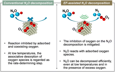 | ||
| Fig. 14 Conceptual diagram of the electric field-assisted catalytic process approach to issues of conventional N2O decomposition reaction. | ||
4.3. N2O adsorption and reduction
Because N2O adsorption can remove trace gases from multicomponent streams and because it can operate at low temperatures, it has been regarded as a promising N2O removal method.114,115 It is a particularly promising method for the recovery and capture of N2O from nitric acid plants and adipic acid plants. High concentrations of N2O (>30 vol%) are present in adipic acid plants, whereas dilute N2O (0.05–0.2 vol%) is present at the exit of nitric acid plants.116 Furthermore, the concentration of N2O by adsorption processes could promote the use of N2O as a useful reagent in synthetic chemistry. For example, N2O could be reused as medical nitrous oxide or as a strong oxidant for the selective oxidation of benzene to phenol.117,118 The appropriate adsorbent must combine several properties, such as high equilibrium adsorption capacity, fast adsorption–desorption kinetics, and high selectivity for N2O.90 Adsorbents of various types have been studied, including activated carbon, silica gel, metal–organic frameworks (MOFs), and zeolites.114,115,119 Yamashita et al. demonstrated that ion-exchanged mordenite zeolites (framework code: MOR), and more specifically calcium and sodium ion-exchanged aluminium-rich MOR zeolites, can exhibit high N2O adsorption capacity in systems supplied with 200 ppm N2O (up to 0.34 mmol-N2O per gram of zeolite at 1 atm, 298 K).114 However, when gases such as CO2 and H2O were present, the N2O adsorption capacity decreased to about half because the adsorption sites were consumed by competitive adsorption. Yue et al. conducted a comprehensive study of N2O adsorption by alkaline and alkaline earth metal ion (Li, Na, K, Mg, Ca, or Ba) exchanged FAU and CHA zeolites.120 At room temperature, Ba-FAU and Na-CHA exhibited remarkable nitrous oxide adsorption of 2.25 mmol g−1 and 2.41 mmol g−1, respectively, at high concentrations of 50![[thin space (1/6-em)]](https://www.rsc.org/images/entities/char_2009.gif) 000 ppm; also, Ba-FAU exhibited good adsorption of 0.35 mmol g−1 at the extremely low concentration of 1000 ppm. The mechanism of N2O adsorption on cationic zeolites and the characteristics of the host–guest interaction were elucidated using in situ FTIR spectroscopy and GCMC simulations. In situ FTIR spectra revealed that N2O molecules are preferentially fixed to the outer framework cations via the terminal oxygen atoms, whereas they are stabilised by the electrostatic interaction with the central nitrogen atoms. This adsorption mode of N2O was well supported by Grand Canonical Monte Carlo (GCMC) simulations. Nitrous oxide molecules prefer to be fixed to the framework cations via the terminal oxygen atoms. Simultaneously, they are stabilised by the framework oxygen through electrostatic interactions with the central nitrogen atoms. This stability might engender the rational design of new adsorbents. In addition, Hiraki et al. reported that NaCaA-85 zeolite exhibited the highest performance of all adsorbents reported to date, with respective N2O adsorption capacities of 1.33 mmol g−1 and 4.69 mmol g−1 at 0.3 and 100 torr.121 Unfortunately, pressurisation is necessary to improve the adsorption capacity, which entails energy loss. Studies of the regeneration of N2O adsorbents have also been conducted in recent years.122–124 In a two-step N2O capture and reduction system that uses CaO-incorporated zeolite (Ca zeolite) as an N2O adsorbent and Pd nanoparticles on La-containing Al2O3 (Pd/La/Al2O3) as an N2O reduction catalyst, the N2O capture capacity and subsequent reduction capacity are maintained for at least 15 h (10 cycles).124 When microwave assistance was combined with 13X zeolite, microwave heating did not change the zeolite structure; moreover, the adsorbent was regenerated completely after the desorption step.122 Trinh et al. combined plasma decomposition with Ca-13X zeolite, which is an N2O adsorbent.123 After 60 min of N2O adsorption using Ca-13X (510 ppm initial concentration, 0.5 L min−1 gas flow rate), adsorbed N2O was plasma-decomposed for 20 min, leading to N2O removal efficiency of 96% at an equivalent ratio input energy of 1.1 kJ L−1.
000 ppm; also, Ba-FAU exhibited good adsorption of 0.35 mmol g−1 at the extremely low concentration of 1000 ppm. The mechanism of N2O adsorption on cationic zeolites and the characteristics of the host–guest interaction were elucidated using in situ FTIR spectroscopy and GCMC simulations. In situ FTIR spectra revealed that N2O molecules are preferentially fixed to the outer framework cations via the terminal oxygen atoms, whereas they are stabilised by the electrostatic interaction with the central nitrogen atoms. This adsorption mode of N2O was well supported by Grand Canonical Monte Carlo (GCMC) simulations. Nitrous oxide molecules prefer to be fixed to the framework cations via the terminal oxygen atoms. Simultaneously, they are stabilised by the framework oxygen through electrostatic interactions with the central nitrogen atoms. This stability might engender the rational design of new adsorbents. In addition, Hiraki et al. reported that NaCaA-85 zeolite exhibited the highest performance of all adsorbents reported to date, with respective N2O adsorption capacities of 1.33 mmol g−1 and 4.69 mmol g−1 at 0.3 and 100 torr.121 Unfortunately, pressurisation is necessary to improve the adsorption capacity, which entails energy loss. Studies of the regeneration of N2O adsorbents have also been conducted in recent years.122–124 In a two-step N2O capture and reduction system that uses CaO-incorporated zeolite (Ca zeolite) as an N2O adsorbent and Pd nanoparticles on La-containing Al2O3 (Pd/La/Al2O3) as an N2O reduction catalyst, the N2O capture capacity and subsequent reduction capacity are maintained for at least 15 h (10 cycles).124 When microwave assistance was combined with 13X zeolite, microwave heating did not change the zeolite structure; moreover, the adsorbent was regenerated completely after the desorption step.122 Trinh et al. combined plasma decomposition with Ca-13X zeolite, which is an N2O adsorbent.123 After 60 min of N2O adsorption using Ca-13X (510 ppm initial concentration, 0.5 L min−1 gas flow rate), adsorbed N2O was plasma-decomposed for 20 min, leading to N2O removal efficiency of 96% at an equivalent ratio input energy of 1.1 kJ L−1.
5. Conclusion and outlook
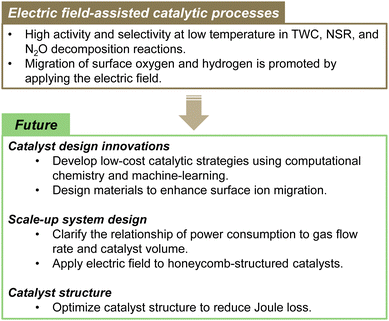
This paper specifically presents the latest developments in NOx and N2O removal technologies, among the environmental issues related to the nitrogen cycle. Both NOx and N2O emissions present urgent difficulties that must be addressed because NOx causes air pollution and acid rain. Moreover, N2O is a powerful greenhouse gas that strongly exacerbates climate change and ozone layer depletion. For the NOx emission from internal combustion engines, the exhaust gas temperature is lowered year by year by virtue of improved combustion efficiency. Therefore, a need exists for catalysts that show high activity at ever-lower temperatures. Purification rates higher than 90% are generally expected to be achievable up to 423 K (US Department of Energy's “150 °C Challenge”).125 Moreover, the development of new catalyst materials and processes is being emphasised to achieve this goal. Conventional technologies have limited activity and stability in low-temperature environments. Further improvements must be made to enhance the conversion of exhaust gas in next-generation conditions. NOx removal technologies that combine external force fields, such as microwave assistance and non-equilibrium plasma assistance, hold some potential to be useful for reducing NOx and N2O at low temperatures. Unfortunately, they entail great amounts of energy consumption.By contrast, electric field-assisted catalytic processes have low energy consumption. The electric field can control ionic conduction on the surface of the oxide support. Consequently, high reaction activity can be achieved even at low temperatures with low energy consumption. Moving forward, catalyst design innovations will specifically emphasise the development of low-cost catalytic strategies through computational chemistry and machine-learning approaches, as well as designing materials that enhance surface ion migration. In terms of scaled-up system design, it will be necessary to clarify the relation of power consumption to gas flow rate and catalyst volume, while exploring the application of electric fields to honeycomb-structured catalysts. Furthermore, optimising catalyst structures to minimise Joule loss is expected to be crucially important for improving overall process efficiency and for advancing this technology toward practical implementation. Ultimately, this technology presents the potential to use surplus power from HV/PHV vehicles for exhaust purification, thereby aiding in energy management as well. Fig. 15 presents an overview of the electric field-assisted catalytic process and future directions.
Technological development for reducing N2O is persistently set as a priority target for future climate change countermeasures. In addition, technologies for controlling N2O emissions from agriculture and sewage treatment are being earnestly sought. There is ongoing development of materials that adsorb low-concentration N2O. In the future, it will also be fundamentally important to develop a technology process for regenerating N2O adsorbents. Therefore, the combination of N2O adsorbents and electric-field-assisted catalysts appears to be promising. Important future prospects include improved low-cost, low-temperature catalysis, and development of new catalyst materials such as alloys or single-atom catalysts (SAC)/dual-atom-site catalysts (DACs), all while enhancing our understanding of energy-saving catalytic processes. Combining these technologies and concepts is hoped to engender the development of innovative exhaust gas purification catalysts. In addition, the collaboration of policy and technological innovation is expected to support the achievement of a more practical and sustainable nitrogen cycle. Further progress is also anticipated in NOx and N2O reduction technology.
Author contributions
Data curation and formal analysis: A. Shigemoto, Y. Sekine, investigation: A. Shigemoto, methodology: A. Shigemoto, visualization: A. Shigemoto, writing – original draft, review & editing: A. Shigemoto, Y. Sekine, conceptualization, project administration and supervision: Y. Sekine.Data availability
The data supporting this article have been included in the manuscript itself and cited literature.Conflicts of interest
There are no conflicts to declare.Notes and references
- J. Rockström, W. Steffen, K. Noone, Å. Persson, F. S. Chapin, E. F. Lambin, T. M. Lenton, M. Scheffer, C. Folke, H. J. Schellnhuber, B. Nykvist, C. A. de Wit, T. Hughes, S. van der Leeuw, H. Rodhe, S. Sörlin, P. K. Snyder, R. Costanza, U. Svedin, M. Falkenmark, L. Karlberg, R. W. Corell, V. J. Fabry, J. Hansen, B. Walker, D. Liverman, K. Richardson, P. Crutzen and J. A. Foley, Nature, 2009, 461, 472–475 CrossRef PubMed.
- K. Richardson, W. Steffen, W. Lucht, J. Bendtsen, S. E. Cornell, J. F. Donges, M. Drüke, I. Fetzer, G. Bala, W. von Bloh, G. Feulner, S. Fiedler, D. Gerten, T. Gleeson, M. Hofmann, W. Huiskamp, M. Kummu, C. Mohan, D. Nogués-Bravo, S. Petri, M. Porkka, S. Rahmstorf, S. Schaphoff, K. Thonicke, A. Tobian, V. Virkki, L. Wang-Erlandsson, L. Weber and J. Rockström, Sci. Adv., 2023, 9, eadh2458 CrossRef PubMed.
- L. Y. Stein and M. G. Klotz, Curr. Biol., 2016, 26, R94–R98 CrossRef CAS PubMed.
- S. Reis, M. Bekunda, C. M. Howard, N. Karanja, W. Winiwarter, X. Yan, A. Bleeker and M. A. Sutton, Environ. Res. Lett., 2016, 11, 120205 CrossRef.
- J. N. Galloway, J. D. Aber, J. W. Erisman, S. P. Seitzinger, R. W. Howarth, E. B. Cowling and B. J. Cosby, BioScience, 2003, 53, 341–356 CrossRef.
- H. Shibata, J. N. Galloway, A. M. Leach, L. R. Cattaneo, L. Cattell Noll, J. W. Erisman, B. Gu, X. Liang, K. Hayashi, L. Ma, T. Dalgaard, M. Graversgaard, D. Chen, K. Nansai, J. Shindo, K. Matsubae, A. Oita, M. C. Su, S. I. Mishima and A. Bleeker, Ambio, 2017, 46, 129–142 CrossRef CAS PubMed.
- N. Gruber and J. N. Galloway, Nature, 2008, 451, 293–296 CrossRef CAS PubMed.
- J. N. Galloway, A. R. Townsend, J. W. Erisman, M. Bekunda, Z. Cai, J. R. Freney, L. A. Martinelli, S. P. Seitzinger and M. A. Sutton, Science, 2008, 320, 889–892 CrossRef CAS PubMed.
- Climate Change 2021: The Physical Science Basis. Contribution of Working Group I to the Sixth Assessment Report of the Intergovernmental Panel on Climate Change.
- K. Hayashi, H. Shibata, A. Oita, K. Nishina, A. Ito, K. Katagiri, J. Shindo and W. Winiwarter, Environ. Pollut., 2021, 286, 117559 CrossRef CAS PubMed.
- X. Zhang, B. B. Ward and D. M. Sigman, Chem. Rev., 2020, 120, 5308–5351 CrossRef CAS PubMed.
- J.-Y. Fang, Q.-Z. Zheng, Y.-Y. Lou, K.-M. Zhao, S.-N. Hu, G. Li, O. Akdim, X.-Y. Huang and S.-G. Sun, Nat. Commun., 2022, 13, 7899 CrossRef CAS PubMed.
- Y. Liu, X. Zhang and J. Wang, Chemosphere, 2022, 291, 132728 CrossRef CAS PubMed.
- S. Xiang, Y. Liu, G. Zhang, R. Ruan, Y. Wang, X. Wu, H. Zheng, Q. Zhang and L. Cao, World J. Microbiol. Biotechnol., 2020, 36, 144 CrossRef CAS PubMed.
- Council of the European Union, Euro 7, 16960/1/23 REV 1, 2023.
- R. M. Heck and R. J. Farrauto, Appl. Catal., A, 2001, 221, 443–457 CrossRef CAS.
- S. Rood, S. Eslava, A. Manigrasso and C. Bannister, Proc. Inst. Mech. Eng., Part D, 2020, 234, 936–949 CrossRef CAS.
- J. Wang, H. Chen, Z. Hu, M. Yao and Y. Li, Catal. Rev., 2015, 57, 79–144 CrossRef CAS.
- S. K. Hoekman, SAE Int. J. Fuels Lubr., 2020, 13, 79–98 CAS.
- T. Nagasawa, A. Kobayashi, S. Sato, H. Kosaka, K. Kim, H. M. You, K. Hanamura, A. Terada and T. Mishima, Chem. Eng. J., 2023, 453, 139937 CrossRef CAS.
- H. M. You, T. Nagasawa, J. W. Lee, H. Kwon and K. Kim, Appl. Surf. Sci., 2024, 648, 159045 CrossRef.
- K. Sato, H. Tomonaga, T. Yamamoto, S. Matsumura, N. D. B. Zulkifli, T. Ishimoto, M. Koyama, K. Kusada, H. Kobayashi, H. Kitagawa and K. Nagaoka, Sci. Rep., 2016, 6, 28265 CrossRef CAS PubMed.
- K. Kusada, D. Wu, Y. Nanba, M. Koyama, T. Yamamoto, X. Q. Tran, T. Toriyama, S. Matsumura, A. Ito, K. Sato, K. Nagaoka, O. Seo, C. Song, Y. Chen, N. Palina, L. S. R. Kumara, S. Hiroi, O. Sakata, S. Kawaguchi, Y. Kubota and H. Kitagawa, Adv. Mater., 2021, 33, 2005206 CrossRef CAS PubMed.
- N. Zhang, C. Ye, H. Yan, L. Li, H. He, D. Wang and Y. Li, Nano Res., 2020, 13, 3165–3182 CrossRef CAS.
- L. Nie, D. Mei, H. Xiong, B. Peng, Z. Ren, X. I. P. Hernandez, A. DeLaRiva, M. Wang, M. H. Engelhard, L. Kovarik, A. K. Datye and Y. Wang, Science, 2017, 358, 1419–1423 CrossRef CAS PubMed.
- J. Tian, K. Khivantsev, Y. Lu, S. Xue, Z. Zhang, J. Szanyi and Y. Wang, ChemCatChem, 2024, 16, e202301227 CrossRef CAS.
- K. Khivantsev, C. G. Vargas, J. Tian, L. Kovarik, N. R. Jaegers, J. Szanyi and Y. Wang, Angew. Chem., Int. Ed., 2021, 60, 391–398 CrossRef CAS PubMed.
- K. Khivantsev, N. R. Jaegers, H. A. Aleksandrov, I. Song, X. I. Pereira-Hernandez, M. H. Engelhard, J. Tian, L. Chen, D. Motta Meira, L. Kovarik, G. N. Vayssilov, Y. Wang and J. Szanyi, J. Am. Chem. Soc., 2023, 145, 5029–5040 CrossRef CAS PubMed.
- Z. Tan, M. Haneda, H. Kitagawa and B. Huang, Angew. Chem., Int. Ed., 2022, 61, e202202588 CrossRef CAS PubMed.
- X. Zhou, K. Han, K. Li, J. Pan, X. Wang, W. Shi, S. Song and H. Zhang, Adv. Mater., 2022, 34, 2201859 CrossRef CAS PubMed.
- H. Asakura, M. Kirihara, K. Fujita, S. Hosokawa, S. Kikkawa, K. Teramura and T. Tanaka, Ind. Eng. Chem. Res., 2020, 59, 19907–19917 CrossRef CAS.
- S. Schemme, R. C. Samsun, R. Peters and D. Stolten, Fuel, 2017, 205, 198–221 CrossRef CAS.
- N. Hooftman, M. Messagie, J. Van Mierlo and T. Coosemans, Renewable Sustainable Energy Rev., 2018, 86, 1–21 CrossRef CAS.
- S. A. Yashnik, Catal. Ind., 2022, 14, 283–297 CrossRef.
- N. Takahashi, H. Shinjoh, T. Iijima, T. Suzuki, K. Yamazaki, K. Yokota, H. Suzuki, N. Miyoshi, S. Matsumoto, T. Tanizawa, T. Tanaka, S. Tateishi and K. Kasahara, Catal. Today, 1996, 27, 63–69 CrossRef CAS.
- W. S. Epling, L. E. Campbell, A. Yezerets, N. W. Currier and J. E. Parks, Catal. Rev.: Sci. Eng., 2004, 46, 163–245 CrossRef.
- S. Matsumoto, Catal. Today, 2004, 90, 183–190 CrossRef CAS.
- S. Roy and A. Baiker, Chem. Rev., 2009, 109, 4054–4091 CrossRef CAS PubMed.
- H. Abdulhamid, E. Fridell and M. Skoglundh, Top. Catal., 2004, 30, 161–168 CrossRef.
- Z. Liu and J. A. Anderson, J. Catal., 2004, 224, 18–27 CrossRef CAS.
- N. W. Cant, I. O. Y. Liu and M. J. Patterson, J. Catal., 2006, 243, 309–317 CrossRef CAS.
- L. Olsson, H. Persson, E. Fridell, M. Skoglundh and B. Andersson, J. Phys. Chem. B, 2001, 105, 6895–6906 CrossRef CAS.
- A. Scotti, I. Nova, E. Tronconi, L. Castoldi, L. Lietti and P. Forzatti, Ind. Eng. Chem. Res., 2004, 43, 4522–4534 CrossRef CAS.
- I. Nova, L. Lietti and P. Forzatti, Catal. Today, 2008, 136, 128–135 CrossRef CAS.
- M. Machida, D. Kurogi and T. Kijima, J. Phys. Chem. B, 2003, 107, 196–202 CrossRef CAS.
- L. Xu and R. W. McCabe, Catal. Today, 2012, 184, 83–94 CrossRef CAS.
- I. Heo, Y. W. You, J. H. Lee, S. J. Schmieg, D. Y. Yoon and C. H. Kim, Environ. Sci. Technol., 2020, 54, 8344–8351 CrossRef CAS PubMed.
- M. Weibel, N. Waldbüßer, R. Wunsch, D. Chatterjee, B. Bandl-Konrad and B. Krutzsch, Top. Catal., 2009, 52, 1702–1708 CrossRef CAS.
- L. Castoldi, R. Bonzi, L. Lietti, P. Forzatti, S. Morandi, G. Ghiotti and S. Dzwigaj, J. Catal., 2011, 282, 128–144 CrossRef CAS.
- S. Schönebaum, J. Dornseiffer, P. Mauermann, B. Wolkenar, S. Sterlepper, E. Wessel, R. Iskandar, J. Mayer, T. E. Weirich, S. Pischinger, O. Guillon and U. Simon, ChemCatChem, 2021, 13, 1787–1805 CrossRef.
- M. Pei, Y. Fan, Y. Li, Y. Huang, H. Xu, J. Wang and Y. Chen, J. Energy Inst., 2024, 114, 101646 CrossRef CAS.
- J. A. Onrubia-Calvo, B. Pereda-Ayo and J. R. González-Velasco, Catalysis, 2020, 10, 208 CAS.
- J. Gao, G. Tian and A. Sorniotti, Energy Sci. Eng., 2019, 7, 2383–2397 CrossRef CAS.
- D. V. Velmurugan, T. McKelvey and J. O. Olsson, IFAC-PapersOnLine, 2021, 54, 526–533 CrossRef.
- K. Kasahara and M. Iwamoto, Handbook of Environmental Catalyst, NTS Co. Ltd., Japan, 2001 Search PubMed.
- T. Souliotis, G. Koltsakis and Z. Samaras, Catalysts, 2021, 11, 539 CrossRef CAS.
- R. F. Horng and H. M. Chou, Proc. Inst. Mech. Eng., Part D, 2003, 217, 183–191 CrossRef.
- W. Xu, J. Cai, J. Zhou, Z. You, Z. Su, N. Shi and Y. Ou, Energy Technol., 2016, 4, 856–863 CrossRef CAS.
- C. Yu, Y. Yi, J. Zhou and W. Xu, Inorg. Chem. Front., 2023, 10, 3808–3820 RSC.
- C. Yu, T. Pan, X. Zhu, Q. Peng, Y. Yi, J. Zhou and W. Xu, Sep. Purif. Technol., 2023, 322, 124281 CrossRef CAS.
- W. Xu, J. Zhou, Z. You, Y. Luo and Y. Ou, ChemCatChem, 2015, 7, 450–458 CrossRef CAS.
- B. Yuan, Z. Qian, Z. Zhangc, L. Fu, S. Pan, R. Hao and Y. Zhao, J. Environ. Sci., 2022, 120, 144–157 CrossRef CAS PubMed.
- L. Bo and S. Sun, Front. Chem. Sci. Eng., 2019, 13, 385–392 CrossRef CAS.
- V. Palma, D. Barba, M. Cortese, M. Martino, S. Renda and E. Meloni, Catalysts, 2020, 10, 246 CrossRef CAS.
- H. H. Kim, Plasma Processes Polym., 2004, 1, 91–110 CrossRef CAS.
- R. Gholami, C. E. Stere, A. Goguet and C. Hardacre, Philos. Trans. R. Soc., A, 2018, 376, 20170054 CrossRef PubMed.
- C. Shi, Z.-S. Zhang, M. Crocker, L. Xu, C.-Y. Wang, C. Au and A.-M. Zhu, Catal. Today, 2013, 211, 96–103 CrossRef CAS.
- Z.-S. Zhang, M. Crocker, B.-B. Chen, Z.-F. Bai, X.-K. Wang and C. Shi, Catal. Today, 2015, 256, 115–123 CrossRef CAS.
- Z.-S. Zhang, M. Crocker, B.-B. Chen, X.-K. Wang, Z.-F. Bai and C. Shi, Catal. Today, 2015, 258, 386–395 CrossRef CAS.
- Z. Bai, Z. Zhang, B. Chen, Q. Zhao, M. Crocker and C. Shi, Chem. Eng. J., 2017, 314, 688–699 CrossRef CAS.
- D. B. Nguyen, N. Matyakubov, S. Saud, I. Heo, S.-J. Kim, Y. J. Kim, J. H. Lee and Y. S. Mok, Environ. Sci. Technol., 2021, 55, 6386–6396 CrossRef CAS PubMed.
- Y. Sekine and R. Manabe, Faraday Discuss., 2021, 229, 341–358 RSC.
- Y. Hisai, Q. Ma, T. Qureishy, T. Watanabe, T. Higo, T. Norby and Y. Sekine, Chem. Commun., 2021, 57, 5737–5749 RSC.
- Y. Sekine, Faraday Discuss., 2023, 243, 179–197 RSC.
- Y. Omori, A. Shigemoto, K. Sugihara, T. Higo, T. Uenishi and Y. Sekine, Catal. Sci. Technol., 2021, 11, 4008–4011 RSC.
- A. Shigemoto, T. Higo, Y. Narita, S. Yamazoe, T. Uenishi and Y. Sekine, Catal. Sci. Technol., 2022, 12, 4450–4455 RSC.
- R. Burch, J. P. Breen and F. C. Meunier, Appl. Catal., B, 2002, 39, 283–303 CrossRef CAS.
- T. Higo, K. Ueno, Y. Omori, H. Tsuchiya, S. Ogo, S. Hirose, H. Mikami and Y. Sekine, RSC Adv., 2019, 9, 22721–22728 RSC.
- A. Shigemoto, Y. Inoda, C. Ukai, T. Higo, K. Oka and Y. Sekine, Chem. Commun., 2024, 60, 1563–1566 RSC.
- P. Kočí, F. Plát, J. Štěpánek, Š. Bártová, M. Marek, M. Kubíček, V. Schmeißer, D. Chatterjee and M. Weibel, Catal. Today, 2009, 147, S257–S264 CrossRef.
- N. Maeda, A. Urakawa and A. Baiker, J. Phys. Chem. C, 2009, 113, 16724–16735 CrossRef CAS.
- J. C. Martinez-Munuera, J. A. Giménez-Mañogil, R. Matarrese, L. Castoldi and A. García-García, Appl. Sci., 2021, 11, 5700 CrossRef CAS.
- R. Inagaki, R. Manabe, Y. Hisai, Y. Kamite, T. Yabe, S. Ogo and Y. Sekine, Int. J. Hydrogen Energy, 2018, 43, 14310–14318 CrossRef CAS.
- M. Torimoto, S. Ogo, Y. Hisai, N. Nakano, A. Takahashi, Q. Ma, J. G. Seo, H. Tsuneki, T. Norby and Y. Sekine, RSC Adv., 2020, 10, 26418–26424 RSC.
- K. Murakami, Y. Tanaka, R. Sakai, Y. Hisai, S. Hayashi, Y. Mizutani, T. Higo, S. Ogo, J. G. Seo, H. Tsuneki and Y. Sekine, Chem. Commun., 2020, 56, 3365–3368 RSC.
- Z. Zhuang, B. Guan, J. Chen, C. Zheng, J. Zhou, T. Su, Y. Chen, C. Zhu, X. Hu, S. Zhao, J. Guo, H. Dang, Y. Zhang, Y. Yuan, C. Yi, C. Xu, B. Xu, W. Zeng, Y. Li, K. Shi, Y. He, Z. Wei and Z. Huang, Chem. Eng. J., 2024, 486, 150374 CrossRef CAS.
- M. Konsolakis, ACS Catal., 2015, 5, 6397–6421 CrossRef CAS.
- X. Wu, J. Du, Y. Gao, H. Wang, C. Zhang, R. Zhang, H. He, G. Lu and Z. Wu, Chem. Soc. Rev., 2024, 53, 8379–8423 RSC.
- E. R. S. Winter, J. Catal., 1974, 34, 431–439 CrossRef CAS.
- F. Kapteijn, J. Rodriguez-Mirasol and J. A. Moulijn, Appl. Catal., B, 1996, 9, 25–64 CrossRef CAS.
- T. Yamashita and A. Vannice, J. Catal., 1996, 161, 254–262 CrossRef CAS.
- H. Dandl and G. Emig, Appl. Catal., A, 1998, 168, 261–268 CrossRef CAS.
- E. V. Kondratenko and J. Pérez-Ramírez, Catal. Lett., 2003, 91, 211–216 CrossRef CAS.
- S. Parres-Esclapez, I. Such-Basañez, M. J. Illán-Gómez, C. Salinas-Martínez de Lecea and A. Bueno-López, J. Catal., 2010, 276, 390–401 CrossRef CAS.
- P. J. Smeets, M. H. Groothaert, R. M. van Teeffelen, H. Leeman, E. J. M. Hensen and R. A. Schoonheydt, J. Catal., 2007, 245, 358–368 CrossRef CAS.
- A. Wang, Y. Wang, E. D. Walter, R. K. Kukkadapu, Y. Guo, G. Lu, R. S. Weber, Y. Wang, C. H. F. Peden and F. Gao, J. Catal., 2018, 358, 199–210 CrossRef CAS.
- J. Arenas-Alatorre, A. Gómez-Cortés, M. Avalos-Borja and G. Díaz, J. Phys. Chem. B, 2005, 109, 2371–2376 CrossRef CAS PubMed.
- K. Pacultová, L. Obalová, F. Kovanda and K. Jirátová, Catal. Today, 2008, 137, 385–389 CrossRef.
- M. Konsolakis, I. V. Yentekakis, G. Pekridis, N. Kaklidis, A. C. Psarras and G. E. Marnellos, Appl. Catal., B, 2013, 138–139, 191–198 CrossRef CAS.
- M. Konsolakis, C. Drosou and I. V. Yentekakis, Appl. Catal., B, 2012, 123–124, 405–413 CrossRef CAS.
- Y. Vadikkeettil, Y. Subramaniam, R. Murugan, P. V. Ananthapadmanabhan, J. Mostaghimi, L. Pershin, C. Batiot-Dupeyrat and Y. Kobayashi, Renewable Sustainable Energy Rev., 2022, 161, 112343 CrossRef CAS.
- X. Tan, H. Chen, L. Shi, Q. Lu, S. Qi, C. Yi and B. Yang, Catal. Lett., 2023, 153, 3724–3733 CrossRef CAS.
- J. O. Jo, Q. H. Trinh, S. H. Kim and Y. S. Mok, Catal. Today, 2018, 310, 42–48 CrossRef CAS.
- L. S. Ko, Y. S. Chen, K. L. Pan and M. B. Chang, Catal. Commun., 2023, 177, 106666 CrossRef CAS.
- O. Muccioli, E. Meloni, S. Renda, M. Martino, F. Brandani, P. Pullumbi and V. Palma, Processes, 2023, 11, 1511 CrossRef CAS.
- E. Meloni, M. Martino, A. Ricca and V. Palma, Int. J. Hydrogen Energy, 2021, 46, 13729–13747 CrossRef CAS.
- A. Shigemoto, T. Higo, C. Ukai, Y. Inoda, K. Mitarai and Y. Sekine, Catal. Sci. Technol., 2024, 14, 4471–4478 RSC.
- M.-J. Kim, H. J. Kim, S.-J. Lee, I.-S. Ryu, H. C. Yoon, K. B. Lee and S. G. Jeon, Catal. Commun., 2019, 130, 105764 CrossRef CAS.
- A. Suda, K. Yamamura, Y. Ukyo, T. Sasaki, H. Sobukawa, T. Tanabe, Y. Nagai and M. Sugiura, J. Ceram. Soc. Jpn., 2004, 112, 581–585 CrossRef CAS.
- S. Ogo, H. Nakatsubo, K. Iwasaki, A. Sato, K. Murakami, T. Yabe, A. Ishikawa, H. Nakai and Y. Sekine, J. Phys. Chem. C, 2018, 122, 2089–2096 CrossRef CAS.
- K. Takise, A. Sato, K. Muraguchi, S. Ogo and Y. Sekine, Appl. Catal., A, 2019, 573, 56–63 CrossRef CAS.
- C. Moreau, Á. Caravaca, P. Vernoux and S. Gil, ChemCatChem, 2020, 12, 3042–3049 CrossRef CAS.
- G. S. Zafiris and R. J. Gorte, J. Catal., 1993, 139, 561–567 CrossRef CAS.
- K. Yamashita, Z. Liu, K. Iyoki, C. T. Chen, S. Miyagi, Y. Yanaba, Y. Yamauchi, T. Okubo and T. Wakihara, Chem. Commun., 2021, 57, 1312–1315 RSC.
- T. Wu, Y. Shen, L. Feng, Z. Tang and D. Zhang, J. Chem. Eng. Data, 2019, 64, 3473–3482 CrossRef CAS.
- Y. Peng, F. Zhang, C. Xu, Q. Xiao, Y. Zhong and W. Zhu, J. Chem. Eng. Data, 2009, 54, 3079–3081 CrossRef CAS.
- K. Severin, Chem. Soc. Rev., 2015, 44, 6375–6386 RSC.
- F. Le Vaillant, A. M. Calbet, S. González-Pelayo, E. J. Reijerse, S. Ni, J. Busch and J. Cornella, Nature, 2022, 604, 677–683 CrossRef CAS PubMed.
- J. Yang, B. Du, J. Liu, R. Krishna, F. Zhang, W. Zhou, Y. Wang, J. Li and B. Chen, Chem. Commun., 2018, 54, 14061–14064 RSC.
- B. Yue, X. Lian, S. Liu, G. Wu, J. Xu and L. Li, Chem. Eng. J., 2023, 462, 142300 CrossRef CAS.
- S. Hiraki, H. Baba, I. Kobayashi, A. Oda, T. Ohkubo, Y. Ikemoto, T. Moriwaki and Y. Kuroda, Chem. Commun., 2024, 60, 4597–4600 RSC.
- E. Meloni, M. Martino, M. Pierro, P. Pullumbi, F. Brandani and V. Palma, Energies, 2022, 15, 4119 CrossRef CAS.
- Q. H. Trinh, S. H. Kim and Y. S. Mok, Chem. Eng. J., 2016, 302, 12–22 CrossRef CAS.
- Y. Jing, C. He, L. Wan, J. Tong, J. Zhang, S. Mine, N. Zhang, Y. Kageyama, H. Inomata, K. Shimizu and T. Toyao, ACS ES&T Eng., 2024 DOI:10.1021/acsestengg.4c00560.
- USDRIVE, Aftertreatment Protocols for Catalyst Characterization and Performance Evaluation: Low-Temperature Oxidation Catalyst Test Protocol, 2015.
| This journal is © The Royal Society of Chemistry 2025 |


