
 Open Access Article
 This Open Access Article is licensed under a Creative Commons Attribution-Non Commercial 3.0 Unported Licence
Multilayer iontronic sensors with controlled charge gradients for high-performance, self-powered tactile sensing†
Haryeong Cho‡
a,
Young-Ryul Kim‡a,
Jaehun Kim‡b,
Seungjae Leea,
Seokhee Junga,
Jeeyoon Kima,
Jinyoung Kima,
Yong-Jin Parka,
Sung-Phil Kim*b and
Hyunhyub Ko *a
*a
aSchool of Energy and Chemical Engineering, Ulsan National Institute of Science and Technology (UNIST), Ulsan Metropolitan City, 44919, Republic of Korea. E-mail: hyunhko@unist.ac.kr
bCollege of Information-Bioconvergence Engineering, Department of Biomedical Engineering, Ulsan National Institute of Science and Technology (UNIST), Ulsan Metropolitan City, 44919, Republic of Korea. E-mail: spkim@unist.ac.kr
First published on 17th May 2025
Abstract
Piezoionic sensors have emerged as a promising class of self-powered tactile sensors, utilizing ion transport within soft materials to convert mechanical stimuli into electrical signals. These sensors offer flexibility, biocompatibility, and the ability to detect both static and dynamic forces, making them highly suitable for wearable electronics, robotic skins, and human–machine interfaces. However, conventional piezoionic sensors suffer from low output signals and slow response times due to inefficient ion transport and charge separation. To address these limitations, we propose a multilayered piezoionic sensor incorporating positively and negatively charged surface layers to create a controlled charge gradient. This design enhances ion mobility and reduces binding energy between ion pairs, and accelerates charge redistribution, leading to significantly improved sensing performance. The proposed sensor achieves an enhanced output current of 1.2 μA and a rapid response time of 19 ms, demonstrating superior sensing performances compared to single-layer designs. Additionally, the sensor effectively detects both static and dynamic forces, including vibration stimuli for surface texture detection, and enables air flow mapping by distinguishing both direction and intensity. By overcoming the fundamental limitations of existing piezoionic sensors, our multilayer approach establishes a new paradigm for high-performance, self-powered tactile sensing, paving the way for next-generation soft electronics and smart sensor systems.
New conceptsWe introduce a novel multilayer piezoionic sensor with charge-modulated ionic composite structures, inspired by biological sensory mechanisms. Unlike conventional piezoionic sensors that suffer from slow ionic transport and low sensitivity, our design strategically incorporates positively and negatively charged surface layers to establish a controlled charge gradient. This charge modulation reduces electrostatic binding between mobile ions, enhancing ion mobility and charge redistribution efficiency. The result is a significant increase in self-powered sensing performance, with a threefold enhancement in output signal compared to single-layer counterparts. Furthermore, this work pioneers a new approach in iontronic sensor design by leveraging charge modulation to achieve selective ion transport, analogous to the function of voltage-gated ion channels in biological systems. This advancement not only enhances the response time and signal strength but also enables the detection of both static and dynamic stimuli with unprecedented precision. By demonstrating a new strategy for charge-controlled ion transport, this study expands the design space for next-generation soft electronics, wearable sensors, and biomimetic tactile interfaces. The proposed multilayer piezoionic sensor establishes a new paradigm in self-powered iontronic sensing, unlocking new possibilities for high-performance, adaptable, and biologically compatible tactile sensing technologies. |
1. Introduction
Tactile sensing is a fundamental capability that allows living organisms to perceive and respond to mechanical stimuli, enabling complex interactions with their environment. The human skin, equipped with specialized mechanoreceptors, detects a wide range of forces, from subtle vibrations to sustained pressure, allowing for precise object manipulation and sensory feedback.1–3 This exceptional sensing capability is driven by ion transport across cell membranes, which generates electrical signals in response to mechanical deformation, forming the basis of biological sensory systems.4,5 At rest, cells maintain an intracellular negative potential ranging from −40 mV to −80 mV relative to the extracellular environment, established by ion concentration gradients. When mechanical stimuli are applied, mechanoreceptor membranes deform, triggering ion channels to open and generating action potentials that encode stimulus information.6,7 Efforts to replicate this biological mechanism have led to significant advancements in artificial tactile sensors, particularly for applications in robotics, human–machine interfaces, and wearable devices. Consequently, the integration of high-resolution tactile sensors with artificial intelligence and robotics has enabled more intuitive human–machine interactions8–10 however, while piezoelectric and triboelectric devices are self-powered and highly responsive to dynamic forces, they rely on electron transport, leading to impedance mismatch with biological ion-based signals.11 Additionally, their rigid structures cause modulus mismatch with soft biological surfaces, limiting conformability and long-term stability.12 They also struggle to detect static forces, as their signal generation relies on transient charge displacement.11 In contrast, iontronic sensors utilize ion transport, mimicking biological sensory mechanisms. This enables seamless bioelectronic integration, continuous static and dynamic force detection, and enhanced mechanical adaptability.13–16 Their soft, flexible, and biocompatible nature allows for efficient interfacing with biological systems, making them well-suited for wearable bioelectronics, robotic skin, and human–machine interfaces.17,18Among iontronic devices, piezoionic tactile sensors stand out for their high sensitivity and ability to conform to complex surfaces, making them particularly advantageous for applications requiring precise and continuous force detection.19–21 The piezoionic effect occurs where mechanical stress induces ion movement, leading to charge imbalances due to differences in ionic mobility. This mechanism involves the selective transport of ions, generating polarization as one type of ion move preferentially over its counterion, creating a net charge imbalance.22–26 This mechanism, analogous to the Donnan potential observed in biological cell membranes,27 offers the advantage of continuous, self-powered sensing without the need for an external power source.28–31 Unlike other self-powered sensing mechanisms, such as piezoelectric and triboelectric effects, which generate electrical signals only in response to instantaneous mechanical stimuli, piezoionic sensors can continuously detect both dynamic forces and static environmental changes using self-generated power.32–35 Their ability to generate self-powered signals, detect load direction, and respond to both static and dynamic stimuli provides unique advantages across various applications. However, current piezoiontronic devices are limited by slow ionic transport kinetics and relatively low sensitivity.36,37
To address these challenges, we propose a multilayer piezoionic sensor with a charge-modulated ionic composite structure. The proposed sensor features an ionic composite layer sandwiched between positively and negatively (P–N) charged layers, reducing electrostatic attraction between ion pairs and enhancing ion mobility. Inspired by voltage-gated ion channels in eukaryotic cells,38 this engineered charge gradient facilitates rapid ion movement and accumulation, significantly improving charge separation and transport dynamics, leading to improved sensing performance. The multilayer sensor exhibits significantly higher electrical double layer (EDL) capacitance (670 μF) than the single layer sensor (230 μF), leading to an output current of 1.2 μA, and a rapid response time of 19 ms, representing a significant advancement over existing piezoionic sensors. The sensor demonstrates excellent stability and reproducibility under various conditions and proves its versatility in real-world applications, such as airflow mapping for detecting both direction and intensity. By leveraging charge-modulated structures, this sensor advances self-powered, high-performance tactile sensing, paving the way for next-generation soft electronics, robotic skin, and environmental monitoring.
2. Results and discussion
2.1. Device preparation
Fig. 1a illustrates a lipid bilayer structure, consisting of two layers of phospholipids with hydrophobic tails forming the membrane core and hydrophilic heads facing the aqueous intra- and extracellular environments. Neutral phospholipids predominantly occupy the outer leaflet, while anionic phospholipids are mainly found in the inner leaflet.39 This asymmetric distribution of phospholipids generates a surface potential of approximately −25 mV, attracting cations and repelling anions. In addition to the surface potential, the membrane potential is also influenced by the Nernst potential, which is determined by the selective permeability of the membrane to different ion species.40,41 Together, these factors regulate ion exchange under external stimuli, facilitating charge redistribution and enabling the initiation of action potentials.42 By mimicking the lipid bilayer structure and potential differences arising from the charge gradient of membrane potential, we designed a P–N charged multilayer piezoionic sensor that modulates ion distribution within the active (ionic composite) layer, as depicted in Fig. 1b. The sensor consists of an ionic composite layer based on a thermoplastic polyurethane (TPU) matrix embedded with EMIM+ TFSI− mobile ions, sandwiched between positively charged poly(diallyldimethylammonium chloride) (PDDA) and negatively charged poly(sodium 4-styrenesulfonate) (PSS) surface layers. These polyelectrolyte layers contain intrinsically charged backbones, which establish the Donnan potential, influencing ion distribution and transport dynamics.43 These P–N charged layers, derived from Donnan potential interactions,23 induce the formation of electrical double layers (EDLs) at the interfaces between the active and charged layers, where counterions accumulate due to electrostatic attraction. Near the negatively charged PSS layer, cations predominantly accumulate, while anions concentrate near the positively charged PDDA layer. This charge redistribution creates potential variations across the sensor, enhancing ion transport and improving its response to external stimuli. | ||
| Fig. 1 Design principle and characterization of the multilayer piezoionic sensor with P–N charged layers. (a) Illustration of biological lipid bilayers showing the arrangement of phospholipids and the resulting membrane potential profile. (b) Biomimetic P–N charged layer configuration, showing ion distribution and electrical double layer (EDL) formation at interfaces. (c) Operating mechanism demonstrating electrostatic interactions between charged layers and mobile ions (EMIM+ and TFSI−), enhancing ion dissociation under mechanical stimulation. (d) Current response comparison, showing ∼3-fold higher sensitivity of the multilayer structure under bidirectional bending deformation. (e) Cross-sectional SEM image and EDS mapping, showing the distinct three-layer structure with Na+ in PSS and Cl− in PDDA layers (scale bar: 10 μm). (f) Open-circuit voltage measurements, showing an inherent potential difference (∼40 mV) in the multilayer device compared to the single-layer configuration. | ||
Fig. 1c schematically illustrates the operating principle of the multilayer piezoionic sensor coated with P–N charged layers. The electrostatic attraction between the P–N charged layers and their counterions (PSS–EMIM+ and PDDA–TFSI−) reduces the binding energy between mobile ions (EMIM+ and TFSI−), facilitating their dissociation under external stimuli. This enhanced ion dissociation increases the number of free mobile ions, allowing for faster ion migration in response to mechanical deformation. As a result, the sensor experiences a greater charge redistribution, leading to a greater ion imbalance between the electrodes, which in turn amplifies the generated electrical signal. When subjected to bending, the multi-layer sensor exhibits a threefold higher current output than the single-layer configuration. This enhanced response is attributed to P–N charged layers enhancing ion dissociation, thereby reducing the binding energy and enhancing the potential difference across the interfaces. Consequently, even small mechanical deformations lead to stronger electrical signal outputs, significantly improving piezoionic performance. The sensor generates a current signal response corresponding to the bending direction, with leftward bending producing a positive current and rightward bending generating a negative current (Fig. 1d).
The multilayer device was fabricated using a stepwise spin-coating process (Fig. S1a, ESI†) on ITO/PET substrates (2 × 2 cm), ensuring each layer was fully dried before deposition. Then, silver nanowires were spray-coated, and electrode extensions were connected. Cross-sectional SEM and EDS elemental mapping confirms a distinct three-layer structure, with Na+ localized in PSS and Cl− in PDDA, showing no intermixing between the DMF-soluble TPU active layer and the water-soluble polyelectrolyte charged layers (Fig. 1e). The total thickness of the sensor is ∼24 μm, consisting of 4 μm for the PSS layer, 16 μm for the active layer, and 4 μm for the PDDA layer (Fig. S2, ESI†). Due to the charge difference between PDDA (+) and PSS (−), the multilayer device exhibits an open-circuit voltage (OCV) of ∼40 mV, whereas the single-layer device shows an OCV near 0 mV (Fig. 1f). This difference is attributed to the higher concentration of ionic species within the polymer chain, which influences the intrinsic potential of the polymer.23 The polymer structures contain distinct pendant groups—SO3− for PSS and ammonium ion (–N+–) for PDDA—resulting in opposite charges in their respective DI water solutions. Zeta potential measurements further confirm these charges, with PSS at −17.5 mV and PDDA at +25.2 mV (Fig. S3a, ESI†). Surface charge characterization is further supported by amplitude modulation Kelvin probe force microscopy (AM-KPFM), which provides spatially resolved surface potential information. As shown in Fig. 2a, the AM-KPFM surface potential maps indicate a higher surface potential for the PDDA film compared to the PSS film. The corresponding histogram of surface potential distributions (Fig. S3b, ESI†) further reinforces this difference, showing distinct potential profiles for each film. These results are consistent with the zeta potential measurements, confirming the positive and negative charges of PDDA and PSS, respectively.
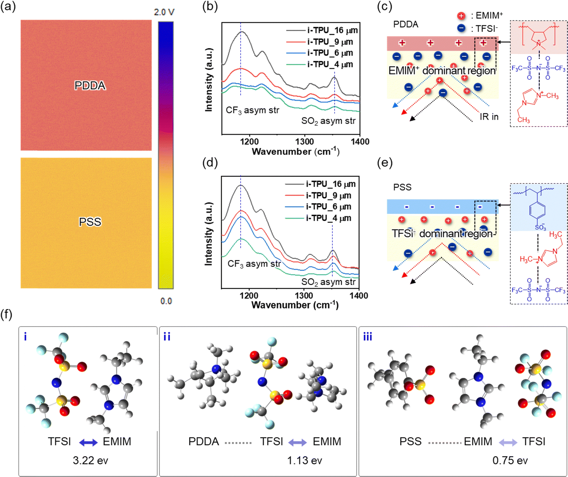 | ||
| Fig. 2 Surface potential analysis and ion distribution characterization in the multilayer piezoionic sensor. (a) Surface potential mapping of PDDA (top) and PSS (bottom) films, showing their distinct charge characteristics. (b) FT-IR spectra of active layers with varying thicknesses on the PDDA substrate, showing TFSI− concentration variation with distance from the interface. (c) Schematic illustration of ion distribution near the PDDA interface, depicting EMIM+ dominant regions formed by electrostatic interactions. (d) FT-IR spectra of active layers with varying thicknesses on the PSS substrate, indicating stable ion distribution. (e) Schematic representation of ion distribution near the PSS interface, showing TFSI− dominant regions. (f) DFT-based binding energy calculations for (i) TFSI−–EMIM+ ion pair (3.22 eV), (ii) PDDA–TFSI−–EMIM+ interaction (1.13 eV), and (iii) PSS–EMIM+–TFSI− interaction (0.75 eV), demonstrating reduced binding energy near charged layers. | ||
The electrostatic interactions between the charged layers and mobile ions were examined by analyzing ion concentration variations across different active layer thicknesses and binding energy calculations. To investigate ion concentration differences of the two ions relative to the distance from the charged layers, active layers with varying thicknesses (4, 6, 9, and 16 μm) were fabricated on PDDA and PSS layers. These samples were then analyzed using attenuated total internal reflection (ATR) spectroscopy (Fig. S4a–c, ESI†). The FT-IR spectra in Fig. 2b illustrate ion distribution relative to the distance between the PDDA surface and the active layer. As the thickness of the active layer decreases, the TFSI− peaks at 1187 and 1353 cm−1, corresponding to CF3 asymmetric stretching and SO2 asymmetric stretching, respectively, diminish, indicating anion accumulation near the PDDA surface.44 The schematic in Fig. 2c further illustrates this ion distribution, where positively charged PDDA attracts anions (TFSI−), leading to anion accumulation near the surface and a cation-enriched region (EMIM+) further from the interface. As the distance from the PDDA surface increases, the electrostatic attraction between anions and the surface weakens, leading to a randomized ionic distribution, similar to that of a bulk layer (Fig. S4d, ESI†). In contrast, Fig. 2d shows no significant variation observed in TFSI− peaks near the PSS surface. This stability is attributed to the symmetrically aligned ion distribution across the PDDA interface, resulting in a higher concentration of negative ions (Fig. 2e). The EMIM+ peaks, associated with CH3(N)HCN stretching, CH3(N) stretching, and CH2(N)CN stretching within 1400–1550 cm−1,45 appear weaker compared to those of the pristine TPU film (Fig. S4e, ESI†). Therefore, IR analysis of EMIM+ ion distribution along the PSS surface distance was ineffective. The binding energy variations, resulting from electrostatic interactions between charged layers and mobile ions, were confirmed through DFT-based quantum mechanical calculations. As depicted in Fig. 2f, the binding energy between two mobile ion species (EMIM+–TFSI−) decreases near the charged surface, with values of 3.22, 1.13, and 0.75 eV corresponding to EMIM+–TFSI−, PDDA–EMIM+–TFSI−, and PSS–EMIM+–TFSI−, respectively. This reduction in binding energy enhances ion dissociation, leading to a higher concentration of free ions when subjected to physical stimuli, thereby improving piezoionic performance.
2.2. Piezoionic properties of the P–N covered multilayer sensor
The piezoionic characteristics of the multilayer sensor, including self-powered electrical signal generation due to charge imbalance under physical stimulation, were examined under bending conditions. To further examine the effect of active layer geometry, texture sensing experiments were performed using sensors with 9, 16, and 24 μm thick active layers. The 16 μm sensor exhibited the most distinct and consistent signal across different textured substrates, while thinner and thicker devices showed reduced performance due to the limited ionic content and weakened charge induction, respectively (Fig. S5, ESI†). In this setup, the fixed multilayer sensor was bent using a solid stimulator mounted on an x–y axis lateral motion stage (Fig. S6a, ESI†). Fig. 3a schematically illustrates the operational principles and the electrical signal generated by bending deformation. When an external force is applied, causing bending deformation, the sensor undergoes tensile strain and compression, leading to redistribution of ion concentration. The strained region exhibits a decrease in ionic concentration, while the compressed region shows an increase, inducing ion flux within the composite.35,46 To restore ionic equilibrium, lighter EMIM+ ions (∼111 g mol−1) migrate faster than heavier TFSI− ions (∼280 g mol−1), resulting in a charge imbalance due to the difference in dominant ion mobility. Moreover, ions at the interface affect the migration of mobile ions within the charged layers, particularly Cl− in PDDA and Na+ in PSS. When the sensor bends to the right, the positively charged interface (enriched with EMIM+ ions) repels Na+ ions, while the negatively charged interface (with excess TFSI− ions) pushes Cl− ions toward the opposite interface. Conversely, when the structure bends to the left, the charge arrangement reverses, and Na+ and Cl− ions experience attractive forces from oppositely charged mobile ions at the interface. | ||
| Fig. 3 Piezoionic sensing capabilities of the multilayer sensor. (a) Schematics of ion distribution in the sensor under different bending states: (i) equilibrium without stimulation, (ii) rightward bending, and (iii) leftward bending. (b) Electrical signal response, showing voltage and current outputs under directional bending cycles. (c) Voltage and current responses for bending angles from 5° to 60°. (d) Impedance characteristics for varying ionic contents (5–20 wt%), showing shifts in charge relaxation frequency. (e) Temporal response time analysis, showing an optimized 19 ms response time. (f) Surface texture recognition, differentiating sandpapers of varying roughness (i–v samples) via STFT spectral patterns. (g) Cycle stability test, showing consistent performance over 5000 bending cycles. | ||
As the sensor deforms, ion redistribution occurs consistently with the bending direction, leading to current flow between the two surface electrodes (Fig. 3b). The dominant ion concentration at each electrode surface varies with the bending direction, causing shifts in the measured potential according to the bending direction. Upon bending release, ions return to their equilibrium state, generating a current in the opposite direction. As shown in Fig. S6b, ESI,† which presents images of different bending degrees, the internal stress increases as the bending angle becomes larger. Due to the piezoionic effect, which depends on applied stress,21,22,47 the electrical signals of the multilayer sensor intensify with increasing bending angles. Consequently, the sensor can effectively detect bending angles ranging from 5 to 60 degrees (Fig. 3c). Bending stimulation was applied at angles of 5, 15, 30, 45, and 60 degrees, with the corresponding electrical outputs confirming the sensor sensitivity. To evaluate the long-term air stability, the same sensor used in the angle-dependent bending test (Fig. 3c) was re-tested after 3 months of ambient storage without encapsulation. As shown in Fig. S7, ESI,† the current responses remained highly consistent, with only minimal variation observed across all bending angles. Even at minimal deformation of 5 degrees, the sensor generates 0.7 mV and 0.4 μA, while at maximum bending of 60 degrees, the outputs significantly increase to 8 mV and 1.2 μA. To further enhance sensing performance, the piezoionic properties of multilayer sensors with different ion concentrations (5, 10, 15, and 20 wt%) were evaluated. Fig. 3d presents the Bode plots, showing both real and imaginary impedance relative to ion concentration. As the ion content increases, bulk film resistance decreases. Additionally, the charge relaxation frequency (τ−1), which represents the crossover frequency between the imaginary and real impedance,45 shifts to higher frequencies, with values of 250, 950 kHz, and 3.5 MHz for 5, 10, and 15 wt%, respectively. The increased ion content reduces polymer chain interactions, enhancing segmental motion of the polymer chains,46,48 which enhances the electrical signal (Fig. S8a–d, ESI†). However, exceeding 20 wt% results in excess bulk ions leaking onto the surface, disrupting the charged layer interface and leading to uneven coating (Fig. S9, ESI†). The optimized multilayer sensor (20 wt% of ionic content) exhibits a response time of 19 ms upon bending and a recovery time of 40 ms when released (Fig. 3e and Fig. S10, ESI†). Fig. 3f illustrates the sensing performance of the multilayer sensor under randomly repetitive deformation, such as vibration stimuli. Owing to its high sensitivity to minute bending, the sensor can differentiate the sandpapers with varying surface roughness, which includes various particle sizes (1, 3, 9, 20, and 40 μm), corresponding to 8000, 4000, 2000, 800, and 400 grit, respectively (Fig. 3f-(i) to (v)). When sweeping across rough surfaces composed of randomly distributed micro-particles, the sensor experiences vibrational deformation, generating current oscillations. After scanning the surfaces of sandpapers, the resulting current data are processed using the short-time Fourier transform (STFT) spectrum. The rough surface with larger particles leads to higher amplitude during vibrational deformation, resulting in a color map transition from blue to yellow-red as the roughness increases. In addition, the sensor exhibits remarkable durability for repeated use, maintaining stable performance for 5000 cycles under large bending deformation (60° bending), as shown in Fig. 3g.
2.3. Comparison of piezoionic capabilities between single and multilayered devices
Fig. 4a and c present the current responses of the single-layer and multilayer sensors, respectively, under varying bending deformations (5, 30, and 60 degree). Although both sensors display increasing current with larger bending angles, the multilayer sensor achieves substantially higher output, reflecting its enhanced ion mobility and charge separation. Fig. 4b and d show the rough surface scanning results for the single-layer (Fig. 4b) and multilayer (Fig. 4d) sensors when traversing surfaces of gradient roughness. The STFT analysis reveals that the multilayer sensor exhibits more pronounced and distinct signal variations in response to changes in surface roughness, showing higher sensitivity to both static bending and vibrational deformations compared to the single-layer sensor (16 μm ionic composite). This improvement is attributed to the charge attraction between the active and charged layers in the multilayer structure, which increases the concentration of free ions in the active layer, amplifying the current output during bending deformation. The ion dynamics within the multilayer structure were further investigated using electrochemical impedance spectroscopy (EIS) under alternative current (AC) voltage (40 mV) with frequencies ranging from 1 to 105 Hz. Fig. 4e presents the Nyquist plot for the single-layer sensor, showing a semicircle with a straight tail, corresponding to the bulk film and electrical double layer (EDL) region, respectively. In contrast, the multilayer sensor exhibits an additional semicircular region, indicating the presence of an ion accumulation layer at the interface between the active and charged layers (Fig. 4f). | ||
Fig. 4 Comparison of piezoionic performance between single-layer and multilayer sensors. (a) Current response of a single-layer sensor under bending deformations (5°, 30°, and 60°). (b) STFT spectral patterns of a single-layer sensor for the rough-surface scanning on a surface with gradient roughness. (c) Current response of a multilayer sensor under bending deformations (5°, 30°, and 60°) and (d) STFT spectral patterns of a single-layer sensor for the rough-surface scanning on a surface with gradient roughness. The color scale bar indicates the STFT intensity level. (e) Nyquist plot of the single-layer sensor, showing bulk film and EDL characteristics. (f) Schematic illustration of ion distribution in the single-layer configuration. (g) Equivalent circuit model for the single-layer sensor. (h) Modified equivalent circuit model for the multilayer sensor, incorporating ion accumulation effects. (i) Frequency-dependent tan![[thin space (1/6-em)]](https://www.rsc.org/images/entities/char_2009.gif) δ curves showing charge relaxation frequency shifts with increasing bending deformation angles. (j) Relationship between the relaxation time and bending angle. δ curves showing charge relaxation frequency shifts with increasing bending deformation angles. (j) Relationship between the relaxation time and bending angle. | ||
The electrical properties were analyzed using an equivalent circuit model. The single-layer sensor was modeled with an electrode resistance (Relect), a parallel RC circuit (Rbulk, Cbulk), and a constant phase element (CPE) for the EDL (Fig. 4g). However, in the multilayer sensor, an additional parallel RC circuit (Rion, Cion) was included to account for the ion-accumulating interface (Fig. 4h). Fitting the equivalent circuit (Fig. S11a, ESI†) reveals that the multilayer sensor presents a significantly higher EDL charge (670 μF) than the single-layer (230 μF), due to interactions between accumulated free ions (EMIM+ TFSI−) and counter-charged ions (Na+ Cl−), leading to the enhanced current generation. To further examine the effect of free ion concentration under bending, EIS analysis was conducted on sensors with low ion concentrations under various deformations. As depicted in Fig. S11b and c, ESI,† the resistance of the bulk film decreases with increasing bending deformation due to the rise in free ion concentration, whereas the single-layer sensor shows no significant resistance variation. The interaction between the charged and active layers influences ionic bonding strength, leading to the release of free ions under external stress, leading to an increase in ionic conductivity.
The frequency dependence of tanδ(ε′′/ε′), where ε′′ and ε′ correspond to the imaginary and real resistance, respectively, was analyzed to investigate free ion density and diffusivity by examining shifts in charge relaxation frequency (τ−1) and dielectric loss.45 As reported in previous studies,46 charge relaxation frequency, the reciprocal of relaxation time (τ = ε/σ = RC, where ε and σ represent the dielectric constant and ionic conductivity, respectively), increases with higher ion concentration due to the enhancement of segmental motion of the polymer chain, facilitating faster ion dynamics. Fig. 4i and j show that the charge relaxation frequency (τ−1) shifts toward higher frequencies as bending increases, confirming the enhanced ion conductivity in the multilayer sensor. The concentration of free ions is a key factor influencing the piezoionic properties, as it governs the charge gradient that facilitates ion movement. In comparison to the single-layer sensor, the multilayer sensor exhibits a more pronounced piezoionic effect, which is directly correlated with an increase in free ion concentration. As the free ion concentration rises, charge redistribution becomes more efficient, leading to a greater piezoionic response in the multilayer sensor system.
2.4. Applications
The multilayer sensor enhances piezoionic performance by adjusting free ion concentration in response to physical stimuli, enabling the detection of subtle vibrational signals. As shown in Fig. S12a–e, ESI,† the sensor demonstrates sound detection capabilities, effectively identifying minute vibrations below 5 kHz when placed 2 cm from a speaker emitting a specific frequency. For the frequency-specific tests described in Fig. S12 (ESI†), SPL values at 100, 500, 1000, and 5000 Hz were measured as 84, 87, 91, and 98 dB, respectively (Fig. S13, ESI†). Fig. 5a describes the sound detection characteristics of our sensor. Electrical signals recorded from Mozart's Marriage of Figaro overture were converted into an STFT spectrum and compared between the piezoionic sensor and a commercial microphone. Both devices accurately recognized frequency variations within the same range. As shown in Fig. 5b, the multilayer sensor can distinguish human voices based on specific frequency components, similar to commercially available microphones. This capability suggests potential applications in personal security systems, such as gender identification based on vocal frequency differences, where lower frequencies correspond to male voices and higher frequencies to female voices.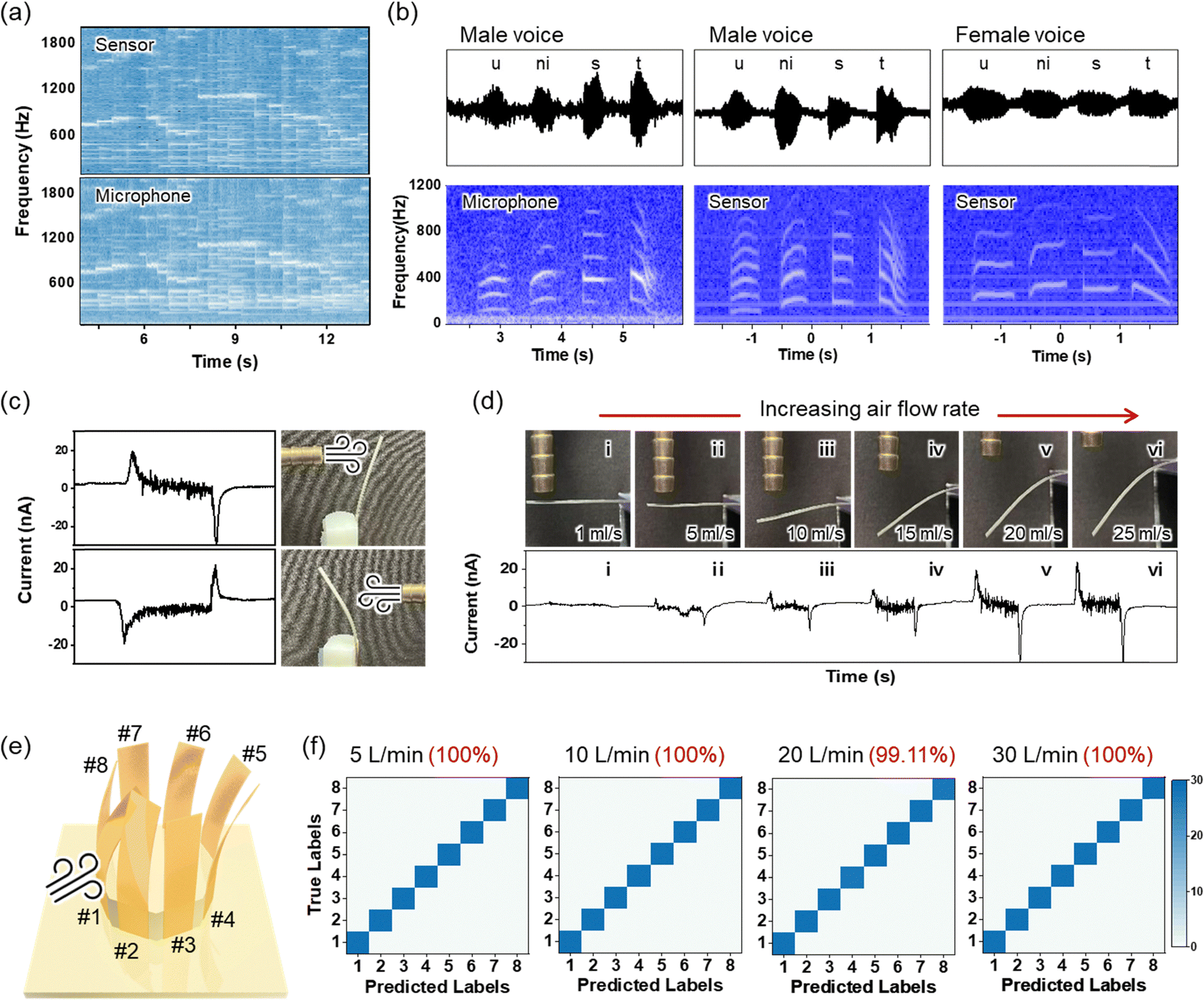 | ||
| Fig. 5 Sound detection and airflow sensing capabilities of the multilayer piezoionic sensor. (a) Frequency spectra comparing sound detection between the piezoionic sensor and a commercial microphone for the recording of Mozart's “The Marriage of Figaro Overture”. The SPL of the speaker sound was 40–80 dB. (b) Voice recognition capability showing waveforms and the corresponding frequency spectra, distinguishing male and female speech components based on frequency distribution. (c) Airflow direction sensing performance, showing current responses with opposite peaks corresponding to different flow directions. (d) Airflow rate sensing performance, showing sensor bending under increasing airflow rates and corresponding current signals (i–vi sequential images). (e) Octagonal sensor array design, enabling wind vane applications. (f) Quantitative airflow measurement capability, showing a consistent sensor response across different pressure levels with high accuracy. | ||
Compared to triboelectric and piezoelectric sensors, our piezoionic multilayer sensors enable the detection of both the direction and magnitude of physical stimuli. Fig. 5c and d illustrate the air flow sensing capabilities of the multilayer sensor, which bends in response to the direction of the air flow, generating opposite current peaks corresponding to the flow direction (Fig. 5c). As the air flow rate increases, the peak current generated by the bending stimulus intensifies, with a corresponding increase in vibration amplitude. The sensor precisely detects air flow rates from 1 to 25 mL s−1, corresponding to 1 and 35 degrees of bending angles, respectively (Fig. 5d). The 1 × 8 pixel sensor array, designed for simultaneous detection of airflow direction and intensity, demonstrates practical applications such as a wind vane (Fig. 5e). The sensor array was fabricated using octagonal 3D-printed support (3 cm diameter). To optimize airflow sensing performance, we investigated the effect of aspect ratio on piezoionic properties (Fig. S14, ESI†). Sensors with a higher aspect ratio (0.5 × 4 cm2 rectangular dimension) exhibited greater bending deformation at the same airflow rate compared to those with a lower aspect ratio (1 × 2 cm2). Therefore, sensors with higher aspect ratios generate stronger electrical signals, including instantaneous and continuous current peaks associated with bending and vibration, along with enhanced STFT intensity due to increased physical stress.
To further validate its performance, the optimized multilayer sensor array was tested across eight wind directions and four airflow rates (5, 10, 20, and 30 L min−1) to validate its ability to simultaneously classify airflow rate and direction (Fig. S15, ESI†). To evaluate performance, four airflow rate conditions (AFR5, AFR10, AFR20, and AFR30) were tested, with 28 repeated trials per condition (i.e., 28 measurements per AD file). The collected multichannel time-series signals were processed to extract features from both time and frequency domains, serving as classifier inputs. For each trial, time-domain features (mean, standard deviation, minimum, maximum, and RMS) were calculated to capture statistical and energy-related properties of the sensor readings. In the frequency domain, a fast Fourier transform (FFT) was applied to obtain total spectral magnitude, maximum amplitude, and the corresponding bin index. By combining these time- and frequency-domain descriptors for each channel into a single high-dimensional feature vector, the airflow stimulus was comprehensively represented in a unified data structure. Classification was carried out through two main approaches. First, in the single airflow rate classification, data from a single airflow rate folder (e.g., AFR5, AFR10, AFR20, or AFR30) were selected, with multiple directional conditions (files) within that folder treated as separate classes. For instance, if the AFR5 folder contained eight direction-specific files, these would form eight distinct classes, classified using a linear support vector machine (SVM) with five-fold cross-validation. As shown in Fig. 5f, this method achieved near-perfect accuracy (100%) for AFR5 and AFR30, while AFR10 and AFR20 maintained high accuracies (99%), indicating that frequency-domain features effectively distinguish flow rate variations. Second, in the multi-class classification, all four airflow rates and their corresponding directions were combined into a single classification task with 32 total classes. Despite the increased complexity, the linear SVM incorporating time–frequency features achieved an accuracy of ∼97% (Fig. S16, ESI†). Some misclassifications occurred among closely related flow rates or directions, which could be improved through advanced spectral analysis (e.g., specific band power or spectral entropy) or high-dimensional feature fusion techniques. In conclusion, the combined time- and frequency-domain feature extraction strategy successfully captured the detailed signal characteristics detected by the multilayer piezoionic tactile sensor, enabling reliable discrimination of airflow rate and direction across 28 repeated experimental trials per condition. This approach can be applied in various domains, including tactile-sensor-based environmental monitoring, robotic perception, and industrial process control. Future improvement, such as analyzing inter-channel correlations, employing wavelet transforms, or utilizing deep learning methods, may further enhance classification accuracy and performance.
3. Conclusion
In this study, we successfully developed a multilayer piezoionic sensor with charge-modulated ionic composite structures inspired by biological sensory mechanisms. By incorporating positively and negatively charged layers, we engineered a controlled charge gradient, which significantly enhanced the ion mobility through reduced electrostatic attraction between ion pairs, leading to improved charge separation and transport dynamics. Electrochemical analysis confirmed the formation of an ion accumulation layer, significantly improving sensor performance. The optimized multilayer sensor demonstrated superior sensing capabilities, achieving an output current of 1.2 μA with a response time of 19 ms, representing a substantial improvement over conventional single-layer sensors. The versatility of this sensor was demonstrated through multiple real-world applications. It successfully distinguished static and dynamic forces, detected surface texture variations, and enabled precise airflow mapping by classifying both direction and intensity with high accuracy (97–100%). Furthermore, its ability to differentiate sound frequencies suggests promising applications in voice recognition and security systems. The sensor also exhibited excellent stability and reproducibility, maintaining consistent performance over 5000 bending cycles. This study presents significant progress in biomimetic sensing devices, offering a new paradigm for designing self-powered, highly sensitive piezoionic devices. The integration of multilayer charge-modulated structures with piezoionic principles not only enhances the sensing performance but also expands potential applications in wearable electronics, robotic skins, environmental monitoring, and human–machine interfaces.4. Experimental
4.1. Preparation of solutions for sensor fabrication
To prepare the thermoplastic polyurethane (TPU)/ion liquid solution, 0.75 g of TPU pellets (K-475A; hardness: Shore A 73, tensile strength: 39.2 MPa, Koron Plastics, South Korea) were dissolved in 5 mL of DMF (N,N-dimethylformamide, Sigma-Aldrich, USA) and stirred at 60 °C for 3 hours. Subsequently, ionic liquid (1-ethyl-3-methylimidazolium bis(trifluoromethylsulfonyl)imide, Sigma-Aldrich, USA) was added at 20 wt% relative to TPU, and the solution was stirred at 60 °C for an additional 2 hours. For the polyelectrolyte layers, both 20 wt% PDDA (poly(diallyldimethylammonium chloride), Sigma-Aldrich, USA) and 30 wt% PSS (poly(sodium 4-styrenesulfonate), Sigma-Aldrich, USA) aqueous solutions were diluted to 15 wt% with deionized (D.I.) water under stirring.4.2. Fabrication process of the multilayer piezoionic sensor
The multilayer piezoionic sensor was fabricated on an ITO/PET electrode substrate (2 × 2 cm2) using a three-step spin-coating process (Fig. S1, ESI†). First, the substrate surface underwent plasma treatment to enhance interfacial adhesion and hydrophilicity. Then, the PDDA solution was spin-coated at 2000 rpm for 60 seconds and dried at 80 °C for 1 hour to form the positive charge layer. Next, the ionic TPU (i-TPU) solution was spin-coated at 500 rpm for 60 seconds and annealed at 80 °C for 12 hours to form the active sensing layer. After another plasma treatment, the PSS solution was spin-coated at 2000 rpm for 60 seconds to form the negative charge layer. To prevent stress-related cracking due to modulus mismatch between TPU and PSS, the PSS layer was slowly dried at room temperature for 3 hours. Finally, flexible silver nanowire (AgNW) electrodes were spray-coated onto the film, and the entire structure was annealed in a convection oven for several hours.4.3. Characterization
The dynamic response and sensing performance of the sensor were evaluated using a source meter (S-2400, Keithley), coupled with a custom-built lateral motion microstage (Micro Motion Technology) for precise deformation control. The structural formation and interfacial characteristics of the multilayer sensor were examined using field emission scanning electron microscopy (FE-SEM, SU7000) and energy dispersive X-ray spectroscopy (Hitachi). The electrochemical behavior was analyzed using an electrochemical impedance analyzer (Iviumstat.h, IVIUM technologies), with data analysis performed using Z-view fitting software. Additionally, the surface morphology and structural configurations of the sensor were analyzed using an optical microscope (BX53, Olympus). The surface potential measurements were carried out using amplitude modulation Kelvin probe force microscopy (AM-KPFM) on a dimension ICON system (Bruker Nano Surfaces, USA). SCM-PIT-V2 probes (Bruker, USA) with 0.01–0.025 Ω cm antimony (n) doped silicon were employed for the measurements.Data availability
The data supporting this article have been included as part of the ESI.†Conflicts of interest
The authors declare no conflicts of interest.Acknowledgements
This work was supported by the National Research Foundation (NRF) of Korea (2021R1A2C3009222 and 2022M3H4A1A02076825) and the National Research Council of Science & Technology (NST) grant by the Korean government (MSIT) (No. CAP22083-201).References
- R. S. Johansson and J. R. Flanagan, Nat. Rev. Neurosci., 2009, 10, 345–359 CrossRef CAS PubMed.
- M. Amjadi, K. U. Kyung, I. Park and M. Sitti, Adv. Funct. Mater., 2016, 26, 1678–1698 CrossRef CAS.
- L. Shi, T. Zhu, G. Gao, X. Zhang, W. Wei, W. Liu and S. Ding, Nat. Commun., 2018, 9, 2630 CrossRef PubMed.
- D. Deflorio, M. Di Luca and A. M. Wing, Front. Hum. Neurosci., 2022, 16, 862344 CrossRef PubMed.
- C. Shang, Q. Xu, N. Liang, J. Zhang, L. Li and Z. Peng, npj Flex. Electron., 2023, 7, 19 CrossRef CAS.
- V. Amoli, J. S. Kim, E. Jee, Y. S. Chung, S. Y. Kim, J. Koo, H. Choi, Y. Kim and D. H. Kim, Nat. Commun., 2019, 10, 4019 CrossRef PubMed.
- G. M. Cooper and K. Adams, The cell: a molecular approach, Oxford University Press, 2022 Search PubMed.
- J. Xi, H. Yang, X. Li, R. Wei, T. Zhang, L. Dong, Z. Yang, Z. Yuan, J. Sun and Q. Hua, Nanomaterials, 2024, 14, 465 CrossRef CAS PubMed.
- F. Huang, X. Sun, Q. Xu, W. Cheng, Y. Shi and L. Pan, Biomimetics, 2025, 10, 147 CrossRef CAS PubMed.
- W. Zheng, Y. Yang, C. Liu and W. Zhou, Sensors, 2023, 23, 3218 CrossRef PubMed.
- K. Y. Chun, Y. J. Son, E. S. Jeon, S. Lee and C. S. Han, Adv. Mater., 2018, 30, 1706299 CrossRef PubMed.
- K. Choi, G. Lee, M.-G. Lee, H. J. Hwang, K. Lee and Y. Lee, Nanomicro Lett., 2025, 17, 180 Search PubMed.
- N. Bai, L. Wang, Q. Wang, J. Deng, Y. Wang, P. Lu, J. Huang, G. Li, Y. Zhang, J. Yang, K. Xie, X. Zhao and C. F. Guo, Nat. Commun., 2020, 11, 209 CrossRef CAS PubMed.
- L. Jia, Z. H. Guo, L. Li, C. Pan, P. Zhang, F. Xu, X. Pu and Z. L. Wang, ACS Nano, 2021, 15, 19651–19660 CrossRef CAS PubMed.
- P. Zhang, W. Guo, Z. H. Guo, Y. Ma, L. Gao, Z. Cong, X. J. Zhao, L. Qiao, X. Pu and Z. L. Wang, Adv. Mater., 2021, 33, 2101396 CrossRef CAS PubMed.
- Z. Lei, Q. Wang, S. Sun, W. Zhu and P. Wu, Adv. Mater., 2017, 29, 1700321 CrossRef PubMed.
- J. C. Yang, J. Mun, S. Y. Kwon, S. Park, Z. Bao and S. Park, Adv. Mater., 2019, 31, 1904765 Search PubMed.
- D. H. Ho, Q. Sun, S. Y. Kim, J. T. Han, D. H. Kim and J. H. Cho, Adv. Mater., 2016, 28, 2601–2608 CrossRef CAS PubMed.
- E. I. Lee and J. W. Park, Adv. Mater. Technol., 2022, 7, 2200691 CrossRef CAS.
- S. Mirza, Y. Dobashi, E. Glitz, M. Farajollahi, S. Mirabbasi, S. Naficy, G. M. Spinks and J. D. Madden, Proc. SPIE, 2015, 9430, 943026 CrossRef.
- Y. Dobashi, D. Yao, Y. Petel, T. N. Nguyen, M. S. Sarwar, Y. Thabet, C. L. Ng, E. Scabeni Glitz, G. T. M. Nguyen, C. Plesse, F. Vidal, C. A. Michal and J. D. Madden, Science, 2022, 376, 502–507 CrossRef CAS PubMed.
- K. Chen and D. Ho, Aggregate, 2024, 5, e425 CrossRef CAS.
- V. Triandafilidi, S. G. Hatzikiriakos and J. Rottler, Soft Matter, 2018, 14, 6222–6229 RSC.
- M. Gudarzi, P. Smolinski and Q.-M. Wang, Sens. Actuators, A, 2017, 260, 99–111 CrossRef CAS.
- G. Tang, Y. Wang, M. Hao, L. Zhang, J. Ru, L. Chang and L. Li, Smart Mater. Struct., 2021, 30, 065013 CrossRef.
- Z. Zhu, X. He, Q. He, X. Fang, Q. Hu and H. Chen, J. Appl. Phys., 2019, 125, 024901 CrossRef.
- P. Aydogan Gokturk, R. Sujanani, J. Qian, Y. Wang, L. E. Katz, B. D. Freeman and E. J. Crumlin, Nat. Commun., 2022, 13, 5880 CrossRef CAS PubMed.
- W. Takashima, T. Uesugi, M. Fukui, M. Kaneko and K. Kaneto, Synth. Met., 1997, 85, 1395–1396 CrossRef CAS.
- T. Shoa, J. D. Madden, T. Mirfakhrai, G. Alici, G. M. Spinks and G. G. Wallace, Sens. Actuators, A, 2010, 161, 127–133 CrossRef CAS.
- G. Alici, G. M. Spinks, J. D. Madden, Y. Wu and G. G. Wallace, IEEE/ASME Trans. Mechatron., 2008, 13, 187–196 Search PubMed.
- K. Sawahata, J. P. Gong and Y. Osada, Macromol. Rapid Commun., 1995, 16, 713–716 CrossRef CAS.
- Y. Liu, Y. Hu, J. Zhao, G. Wu, X. Tao and W. Chen, Small, 2016, 12, 5074–5080 CrossRef CAS PubMed.
- B. H. Moghadam, M. Hasanzadeh and A. Simchi, ACS Appl. Nano Mater., 2020, 3, 8742–8752 CrossRef CAS.
- S. M. Villa, V. M. Mazzola, T. Santaniello, E. Locatelli, M. Maturi, L. Migliorini, I. Monaco, C. Lenardi, M. Comes Franchini and P. Milani, ACS Macro Lett., 2019, 8, 414–420 CrossRef CAS PubMed.
- Y. Wu, G. Alici, J. D. Madden, G. M. Spinks and G. G. Wallace, Adv. Funct. Mater., 2007, 17, 3216–3222 CrossRef CAS.
- D. Ho, ChemElectroChem, 2024, 11, e202300268 CrossRef CAS.
- J. Yin, P. Jia, Z. Ren, Q. Zhang, W. Lu, Q. Yao, M. Deng, X. Zhou, Y. Gao and N. Liu, Research, 2025, 8, 0571 CrossRef CAS PubMed.
- L. Catacuzzeno and F. Franciolini, J. Physiol., 2022, 600, 3227–3247 CrossRef CAS PubMed.
- Y. Ma, K. Poole, J. Goyette and K. Gaus, Front. Immunol., 2017, 8, 1513 CrossRef PubMed.
- D. E. Goldman, J. Gen. Physiol., 1943, 27, 37–60 CrossRef CAS PubMed.
- A. L. Hodgkin and A. F. Huxley, J. Physiol., 1952, 117, 500–544 CrossRef CAS PubMed.
- H. Q. Huynh, T. Q. Trung, A. Bag, T. D. Do, M. J. Sultan, M. Kim and N. E. Lee, Adv. Funct. Mater., 2023, 33, 2303535 CrossRef CAS.
- K. Prudnikova and M. Utz, Macromolecules, 2012, 45, 1041–1045 CrossRef CAS.
- J. Kiefer, J. Fries and A. Leipertz, Appl. Spectrosc., 2007, 61, 1306–1311 CrossRef CAS PubMed.
- E. K. Boahen, B. Pan, H. Kweon, J. S. Kim, H. Choi, Z. Kong, D. J. Kim, J. Zhu, W. B. Ying, K. J. Lee and D. H. Kim, Nat. Commun., 2022, 13, 7699 CrossRef CAS PubMed.
- Y.-R. Kim, G. Lim, H. Cho, J. Kim, J. Kim, J. Yeom, D.-H. Kang, H. Lee, D. Lim, S.-P. Kim and H. Ko, Nano Energy, 2024, 127, 109749 CrossRef CAS.
- G. Di Pasquale, S. Graziani, A. Latteri, A. Pollicino and C. Trigona, Appl. Sci., 2024, 14, 1085 CrossRef CAS.
- D. Bresser, S. Lyonnard, C. Iojoiu, L. Picard and S. Passerini, Mol. Syst. Des. Eng., 2019, 4, 779–792 RSC.
Footnotes |
| † Electronic supplementary information (ESI) available. See DOI: https://doi.org/10.1039/d5mh00503e |
| ‡ Haryeong Cho, Young-Ryul Kim, Jaehun Kim contributed equally to this work. |
| This journal is © The Royal Society of Chemistry 2025 |