
Polymer–metal nanocomposites with bi- or tri-metallic compositions exhibiting catalytic properties†
Nicholas Kai Shiang
Teo
a,
Yi
Huang
 ab and
San H.
Thang
*a
ab and
San H.
Thang
*a
aSchool of Chemistry, Monash University, Clayton, VIC 3800, Australia. E-mail: san.thang@monash.edu
bEngineering Research Center for Eco-Dyeing and Finishing of Textiles, Ministry of Education, Zhejiang Sci-Tech University, Hangzhou, 310018, China
First published on 25th March 2025
Abstract
The use of hybrid materials such as polymer–metal nanocomposites (PMNCs) in heterogeneous catalysis has rapidly gained attention in recent years due to their enhanced catalytic performance and significantly different physicochemical properties compared to their larger counterparts. Traditional techniques for preparing PMNCs involve the use of capping/stabilising agents that wrap around metal nanoparticles (MNPs), forming a barrier that limits active site availability and reduces catalytic efficiency. This paper presents an approach for preparing gold (Au), palladium (Pd) and silver (Ag)-based PMNCs in situ via ultrasonic treatment with unobstructed MNPs attached to amine functionalities located on the surface of polymeric chains synthesised from reversible addition–fragmentation chain-transfer (RAFT) polymerisation-induced self-assembly (RAFT-PISA). High resolution transmission electron microscopy (HR-TEM) imaging and energy-dispersive X-ray (EDX) mapping confirmed the successful preparation of these PMNCs. The catalytic performances of these PMNCs are evaluated against well-known organic reactions such as the aerobic oxidation of 1-phenylethanol and the Suzuki–Miyaura cross-coupling reaction between 4-iodophenol and phenylboronic acid, where the performance of the bimetallic Au–Pd PMNC and the bimetallic Ag–Au PMNC reached as high as 94% and 98.5% for each respective reaction at a concentration of 0.02 mol%. Additionally, the catalytic performance of the trimetallic Ag–Au–Pd PMNC was discovered to be 39.8% and 96.0%, respectively, for both reactions at the same concentration. This work aims to expand the knowledge of PMNCs and promote their utility as advanced heterogeneous catalysts in organic reactions.
Introduction
Hybrid materials such as nanoclusters, nanoparticles (NPs), and polymer–metal nanocomposites (PMNCs) have attracted much attention in recent years, as they can potentially be used in a wide range of fields such as biotechnology, particularly in diagnostic imaging,1,2 electronic storage systems,3 advanced drug targeting and delivery systems,2,4 and in the important area of heterogeneous catalysis.5–7 Such nanomaterials offer larger surface area-to-volume ratios, as opposed to their bulk counterparts, giving rise to enhanced physicochemical properties. As opposed to preparing such nanocomposites using conventional capping/stabilising agents (surface-active agents) such as citrates and dodecyl sulphates,8 which can have the potential to block reactant access and negatively affect catalytic properties,9 polymeric nanoparticles present an advanced yet simple method of supporting these metal nanoparticles (MNPs) via immobilisation on the surface of these polymers, which helps to prevent MNPs from aggregation and losing their unique properties.10 These polymeric nanoparticles act as scaffolds to MNPs such as gold nanoparticles (AuNPs), palladium nanoparticles (PdNPs) and silver nanoparticles (AgNPs), freeing them from external capping agents and maximising the available exposed surface area for high-efficiency catalysis.PMNCs are commonly prepared from the combination of polymer nanoparticles and the growth of MNPs on the surface of these particles. Polymer nanoparticles containing tertiary amine groups from monomers such as N,N-dimethylaminoethyl methacrylate (DMAEMA) can be produced by either solution self-assembly (SSA) processes11 or polymerisation-induced self-assembly (PISA) processes.12 As opposed to the limitations of SSA such as low polymer concentration, solid content, complicated preparation methods and scalability issues,13,14 PISA, on the other hand, enables the in situ self-assembly of these polymers into nanoparticles with various morphologies.15 In addition, PISA allows for polymerisations at higher solid contents of up to 50% with a tuneable degree of polymerisation (DP) for controlled reactions.16 The concept of MNP formations was explained by Toshima, where metal ions (salts) or complexes can be reduced or deposited respectively to form individual metal atoms which are unstable and quickly aggregate to form metal seeds (nuclei), through which more atoms or seeds can be deposited onto them to grow into MNPs.17 These MNPs can be prepared via in situ methods such as ultrasonic reduction of their respective salt form and, in the presence of a polymer nanoparticle, they can be immobilised on the surface to form PMNCs through strong chemisorption interactions with the tertiary amine groups. For example, Mahdavian et al. used a stimuli-responsive poly(2-(N,N-dimethylamino)ethyl methacrylate) (PDMAEMA) polymer as both a supporting substrate and a reducing agent to synthesise AuNPs with tuneable UV-Vis absorption wavelengths and plasmonic properties sensitive to both pH and temperature.18 The resulting Au-PDMAEMA species displayed significant localised surface plasmon resonance (LSPR) effects within the pH range of 6–8 and a shift in the lower critical solution temperature (LCST) as compared to the free DMAEMA monomeric chains. Moreover, they are stable even after six months of synthesis under static and ambient conditions, proving their suitability in catalytic applications. Li and Yang et al. reported a novel route to coat polystyrene particles with a layer of Pd@polypyrrole (PdNP@PPy) nanocomposites, leading to a well-defined core–shell structure.19 Due to the small size and well-dispersed nature of the PdNPs on the nanocomposites, these nanocomposites demonstrated high catalytic efficiency and good reusability until the fourth cycle in the reduction of p-nitrophenol with sodium borohydride (NaBH4) as a reducing agent. A study by Kyrychenko et al. explored the behaviour of poly(methyl methacrylate)-block-poly(2-(N,N-dimethylamino)ethyl methacrylate) (PMMA-b-PDMAEMA) coated with a layer of AgNPs under the influence of different pH values using atomistic molecular dynamics (MD) simulation.20 Interestingly, MD revealed that for a single PMMA-b-PDMAEMA oligomer, the PMMA block preferably interacts with the AgNP surfaces while the PDMAEMA chains are capable of creating up to 58 hydrogen bonds with surrounding water molecules when completely protonated, which allows for a tuneable “smart” polymeric shell to deliver AgNPs in targeted drug delivery systems.
Another attractive feature of MNPs is their synergistic ability to combine different monometallic NPs into bimetallic or even trimetallic forms, which helps to improve their overall stability and catalytic performance as the interaction between MNPs can accelerate electron density movements.21 Additionally, the resultant hybrid MNPs can also show distinct geometric properties compared to their monometallic counterparts (i.e. shape, crystal facets, overall charge, oxidation states, etc.), requiring advanced characterisation methods to differentiate the bonding type within the metallic structure (i.e. core–shell, alloy formation, etc.), which may prove to be difficult to accomplish given the complex nature of such systems.22 To elaborate on such observations, Ahmed and Emam reported on the synergistic behaviour between AuNPs, PdNPs and AgNPs in the reduction of p-nitrophenol where the tri-metallic catalyst Ag–Au–Pd@dextran increased the rate of reduction by 151 times as opposed to its mono-metallic counterparts.23 Dwivedi and Nandi et al. explored the catalytic ability of bimetallic Ag–Au alloy NPs stabilised using a poly(diallyldimethylammonium) chloride (PDADMAC) cationic polymer system and found that their efficiencies depend highly on the gold content, with a higher gold content leading to better catalyst performance in the reduction of p-nitrophenol.24
In our previous work, we have demonstrated the ability to use ultrasound at 990 kHz as a “green” approach for in situ reversible addition–fragmentation chain-transfer (RAFT) polymerisation of a poly(ethylene glycol)-based block copolymer (sono-RAFT-PISA) in water to synthesise spherical and worm-like nano-objects15 and also the characterisation of monometallic AuNPs and PdNPs immobilised onto their polymeric surfaces.5 In this study, we are interested in exploring, in greater detail, the catalytic performances of different combinations of AuNPs, PdNPs and AgNPs immobilised onto polymer nanoparticle surfaces against the aerobic oxidation of 1-phenylethanol and the Suzuki–Miyaura cross-coupling reaction between 4-iodophenol and phenylboronic acid with comparisons made to their monometallic counterparts.
Results and discussion
Synthesis of PEG113-b-PDMAEMA-b-PHPMA-CDTPA triblock copolymer nanoparticles via RAFT-PISA
According to a previously reported procedure, poly(ethylene glycol), mPEG113 (average Mn = 5000, 113 units of ethylene glycol moiety) reacted with the RAFT agent 4-cyano-4-(((dodecylthio)carbonothioyl)thio)pentanoic acid (CDTPA) via Steglich esterification to synthesise the macro-chain transfer agent (macro-CTA) PEG113-CDTPA (Scheme 1(a)) as the first block, which was characterised using 1H and 13C NMR spectroscopy (Fig. S1†).15 Subsequently, PEG113-CDTPA was chain extended with the DMAEMA monomer containing a tertiary amine moiety in the 1,4-dioxane solvent via RAFT polymerisation to yield the PEG113-b-PDMAEMA-CDTPA diblock copolymer (Scheme 1(b)). To study the effects of PDMAEMA chain lengths on the formation of polymeric nanoparticles and polymer–metal nanocomposites (PMNCs), PEG113-b-PDMAEMA-CDTPA samples were synthesised and tabulated (Table S1†). The number average molecular weights (Mn) of each polymer sample, determined via1H NMR (Mn,NMR) theoretically from the initial concentrations of starting materials (Mn,theoretical) and via gel permeation chromatography (GPC) using N,N-dimethylformamide (DMF) as a solvent and poly(methyl methacrylate) (PMMA) as a standard (Mn,GPC), were compared and found to increase with an increase in the DP of the DMAEAM block. GPC results revealed that all block copolymers synthesised in this manner exhibit low dispersity (Đ, 1.14–1.19) values, indicating excellent polymerisation control of the DMAEMA block (Table S1†). The normalised GPC traces of PEG113-CDTPA and PEG113-b-PDMAEMA-CDTPA with varying DPs of the PDMAEMA block show a bimodal distribution pattern, with a small side shoulder peak which can be attributed to the mPEG113 moiety (Fig. S5†).5 It was noted that the molecular weight values obtained from the GPC were higher than those determined from NMR spectra or through theoretical calculations. A shift to shorter retention times was observed as the DP of the PDMAEMA block increases, which is supported by an increase in overall molecular weights (Table S1†) and can be explained by the fact that longer polymer chains interact less strongly with the GPC column stationary phase compared to shorter polymer chains. In addition, the Mn,GPC values determined for all PEG113-CDTPA and PEG113-b-PDMAEMA- CDTPA samples were higher than their respective Mn,NMR or the Mn,theoretical values, due to the GPC being calibrated using PMMA standards, which is structurally different from PEG. The PDMAEMA block in PEG113-b-PDMAEMA16-CDTPA was deemed too short to provide enough tertiary amine sites for metal nanoparticle capture, while the PDMAEMA block in PEG113-b-PDMAEMA50-CDTPA was too long and required a comparatively higher DP than that of the PHPMA core-forming block to stabilise the resulting polymer morphology formed. Therefore, PEG113-b-PDMAEMA32-CDTPA was chosen for subsequent studies as a compromise between the number of tertiary amine sites and the amount of PHPMA needed to form the final polymer morphology. | ||
| Scheme 1 (a) Synthesis of PEG113-CDTPA via Steglich esterification. (b) Synthesis of PEG113-b-PDMAEMA-CDTPA to incorporate the tertiary amine moiety responsible for anchoring MNPs. (c) Synthesis of PEG113-b-PDMAEMA-b-PHPMA-CDTPA triblock copolymers via thermal RAFT-PISA to form milky stable suspensions. | ||
For thermally-initiated RAFT-PISA formulations, PEG113-b-PDMAEMA32-CDTPA was chain extended with the HPMA monomer to form PEG113-b-PDMAEMA32-b-PHPMA-CDTPA triblock copolymers as stable milky-white dispersions kept at an overall solid content of 10% w/w (Scheme 1(c)). For these formulations, heat and a water-soluble initiator, VA-044, were used to initiate the reaction and to produce the final product. These dispersions were subsequently analysed by 1H NMR spectroscopy and GPC, confirming the near consumption of all monomers and their conversion into polymers. Different batches of PEG113-b-PDMAEMA32-b-PHPMA-CDTPA with variations in the PHPMA block lengths were successfully synthesised by changing the target DP (Table 1). Upon increasing the target DP of the PHPMA block from 100 to 800, the actual DP obtained by calculating the NMR conversion decreased slightly from 100.0% to 98.5% (Table 1, entries 1–6). The corresponding increase in Đ values from 1.17 to 1.87 was a result of a greater extent of inter-molecular hydrogen bonding between PHPMA chains, causing a wider distribution of the final average hydrodynamic diameter from 45.0 ± 14.5 (Table 1, entry 1) to 306.7 ± 70.0 (Table 1, entry 6) as measured by dynamic light scattering (DLS) and from 31.6 ± 23.8 (Table 1, entry 1) to 260.1 ± 51.1 (Table 1, entry 6) as measured by transmission electron microscopy (TEM). Nevertheless, the polydispersity index (PDI) values taken from DLS indicated a narrow size distribution of these nanoparticles, which is beneficial for their subsequent use as heterogeneous catalysts. Previous studies on this polymerisation system indicated that this has minimal to no effect on the subsequent characterisation studies conducted and in the testing of the resulting PMNCs.15 For this study, PEG113-b-PDMAEMA32-b-PHPMA398-CDTPA copolymer particles with a well-defined vesicular structure are chosen for the in situ formation of PMNCs.
| Entry | Target DP of the HPMA monomer | Actual DP of the PHPMA blocka | NMR conversionb (%) |
M
n,NMR![[thin space (1/6-em)]](https://www.rsc.org/images/entities/char_2009.gif) c (g mol−1) c (g mol−1) |
M
n,theoreticald (g mol−1) |
M
n,GPCe (g mol−1) |
Đe |
Average diameterf (DLS) (nm) | PDIf (DLS) | Average diameter (TEM)g (nm) |
|---|---|---|---|---|---|---|---|---|---|---|
| a Actual DP was determined through 1H NMR spectra. b Determined by comparing the ratio of the CH3 peak (0.8–0.9 ppm) to the product CH peak (4.6–4.9 ppm) (Fig. S6–S11†). c M n,NMR = Mn,PHPMA × Mn,PEG113-PDMAEMA32-CDTPA × NMR conversion (%). d M n,theoretical = Mn,HPMA × Mn,PEG113-PDMAEMA32-CDTPA × target DP of the PHPMA block. e Determined using DMF-GPC with PMMA as a standard. f Average diameter and standard deviation obtained from the DLS instrument. g Average diameter and standard deviation obtained from TEM by measuring at least 30 random nanoparticles. | ||||||||||
| 1 | 100 | 100 | 100.0 | 24800 |
24800 |
44700 |
1.17 | 45.0 ± 14.5 | 0.24 | 31.6 ± 23.8 |
| 2 | 200 | 198 | 99.0 | 38900 |
39200 |
71400 |
1.27 | 183.0 ± 35.6 | 0.19 | 167.2 ± 72.1 |
| 3 | 300 | 297 | 99.2 | 53200 |
53700 |
95200 |
1.36 | 205.3 ± 41.5 | 0.17 | 209.8 ± 63.9 |
| 4 | 400 | 398 | 99.5 | 67800 |
67800 |
120100 |
1.48 | 204.0 ± 45.8 | 0.13 | 220 ± 72.3 |
| 5 | 600 | 593 | 98.8 | 95900 |
96900 |
169200 |
1.64 | 307.2 ± 56.3 | 0.10 | 305.1 ± 48.4 |
| 6 | 800 | 788 | 98.5 | 124000 |
125700 |
222200 |
1.87 | 306.7 ± 70.0 | 0.19 | 260.1 ± 51.1 |
The photographed stable copolymer dispersions (Fig. 1(a)) showed a gradual increase in cloudiness, indicating the formation of stable polymeric nanoparticles. They were then analysed using DMF-GPC (PMMA standards), DLS and TEM. As the DP of the PHPMA block increases from 100 to 788, there is a noticeable shift to a lower retention time (Fig. 1(b)) as the average diameter of the particles increases as shown in the DLS traces (Fig. 1(c)). The small bump on the left side of the GPC trace of PEG113-b-PDMAEMA32-b-PHPMA788-CDTPA can be explained by the fusion of larger particles (Fig. 1(i)) to form a fibroid-like structure with internal collapse of the compound vesicular core, leading to the formation of slightly larger than expected particles and hence eluting out faster. The small bump on the DLS trace for PEG113-b-PDMAEMA32-b-PHPMA100-CDTPA refers to a small percentage of dimerised copolymer particles via the PHPMA block which is especially obvious at a low DP of the PHPMA block and is absent as the DP increases. As the internal structure of these polymeric particles becomes more complex, the average hydrodynamic diameter also increases. Interestingly, there is minimal to no observable increase in particle diameter going from the PHPMA block DP of 593 (Fig. 1(h)) to 788 (Fig. 1(i)), even though there is a change in the particle morphology. This observation can be explained through a fusion process that creates a huge network of inter-connected channels at the expense of individual particle size, hence leading to almost no change in the overall particle diameter. TEM images obtained revealed a change in the morphology of these copolymer particles from small spheres (Fig. 1(d)) to a transition-like phase of short worm vesicles (Fig. 1(e)), to well-defined vesicles (Fig. 1(f) and (g)), to multi-compartmental vesicles (Fig. 1(h)) to fused multi-compartmental vesicles with a fibre-like structure (Fig. 1(i)).
 | ||
| Fig. 1 (a) Images of PEG113-b-PDMAEMA32-b-PHPMAy-CDTPA PISA nanoparticles with an increase in the DP (y = 100–788) of the PHPMA block against a black background. (b) Normalised GPC traces and (c) DLS traces of PEG113-b-PDMAEMA32-b-PHPMAy-CDTPA PISA nanoparticles. (d)–(i) TEM images corresponding to PEG113-b-PDMAEMA32-b-HPMAy-CDTPA PISA nanoparticles with an increase in the DP (y = 100–788) of the PHPMA block. | ||
In situ synthesis of PMNCs
In 2006, Blanchard reported the ability of tertiary amine groups to capture and bind onto MNPs such as gold nanoparticles (AuNPs) due to the chemisorption effect.25 From a thermodynamic standpoint, they found that for a spontaneous reaction between amine groups (NR3) and HAuCl4, the oxidation potential of the amine must be between the range of reduction potentials of HAuCl4 to Au0 and the oxidation potentials of Au0 to Au1+, leading to unconjugated amines being the best candidates for such systems. Filippo experimented on the in situ synthesis of silver nanoparticles (AgNPs) from silver nitrate via microwave irradiation, with glucose as the reducing agent and sucralose as the capping agent.26 Addition of triethylamine of varying concentrations and reaction times acted as the promoter and directing agent, allowing for direct observation of colour changes in the final reaction mixture, hence proving the usefulness of amines in the synthesis of MNPs from their corresponding metal salts.In 2021, our group reported on a novel method of producing AuNPs and PdNPs decorated onto the surface of polymers through interactions with the PDMAEMA moiety on the spherical PEG113-b-PDMAEMA-b-PHPMA-CDTPA triblock copolymer nanoparticles to produce Au@PEG113-b-PDMAEMA-b-PHPMA-CDTPA and Pd@PEG113-b-PDMAEMA-b-PHPMA-CDTPA PMNCs separately.5 However, Armes et al. noted that a certain percentage of the PDMAEMA moiety in a polymer containing this functional group will be protonated upon the addition of HAuCl4, which will negatively affect the ability to reduce AuCl4− ions via a coordination–reduction mechanism.27 As such, instead of using metal salts containing H+ as positively-charged counterions, we used metal salts containing Na+ counterions instead to minimise the protonation of the PDMAEMA block. In addition, we also noticed that this reduction process does not require any external reducing agent to perform or aid in the reduction. Thus, in a standard procedure, the final PMNC mixture was prepared by simply mixing diluted copolymer nanoparticles, metal salts (NaAuCl4, Na2PdCl4 and AgNO3) and an external polymeric stabiliser termed poly(N-vinylpyrrolidone) (PNVP) (Scheme 2(a) and (b)). The purpose of the external stabiliser is to aid in capturing any loose or unbound MNPs after the ultrasonic reduction process and minimise colloids from forming, and such a low concentration of PNVP (0.2 mg mL−1) was chosen according to previous studies.5 With the incorporation of ultrasound and the absence of an external reducing agent, a relatively “green” approach has been developed to reduce metal salts to their respective MNPs.
 | ||
| Scheme 2 (a) Schematic illustration of the formation of Au/Ag/Pd@PEG113-PDMAEMA-PHPMA-CDTPA polymer–metal nanocomposites (PMNCs) via in situ ultrasonic reduction of metal salts to their respective metal nanoparticles. PMNCs are then used for the alcohol aerobic oxidation of 1-phenylethanol to acetophenone and the Suzuki–Miyaura cross coupling reaction between 4-iodophenol and phenylboronic acid to form 4-phenylphenol. (b) Co-synthesis of Au/Ag/Pd@PNVP PMNCs via a similar reaction with PNVP acting as an external stabiliser. | ||
UV-Vis spectra were recorded and analysed for the different combinations of Au/Ag/Pd@PEG113-b-PDMAEMA32-b-PHPMA398-CDTPA PMNCs, with the maximum wavelength absorption (λmax) occurring at 438 nm for the Ag@polymer, 543 nm for the Au@polymer, 532 nm for the Ag–Au@polymer, and 515 nm for the Au–Pd@polymer (Fig. 2(a)). In contrast, no λmax was observed for the Pd@polymer, Ag–Pd@polymer, and Ag–Au–Pd@polymer. This is an interesting phenomenon because such an observation was also noticed by Epple et al., where MNPs that adopt a Pd shell-like structure did not show any distinct absorption in the visible light range.28 The presence of Pd covering the surfaces of these polymeric nanoparticles prevented the LSPR effects of AuNPs and AgNPs and might even help to confirm the formation of core–shell-like MNP nanostructures.29 Selected area electron diffraction (SAED), TEM and high-resolution TEM (HR-TEM) were performed on all PMNC samples, and the Ag–Au–Pd@polymer was chosen for discussion. By analysing the ring patterns on the SAED image, various concentric bright rings made up of countless dots can be allocated to the different lattice planes of Ag, Au and PdNPs ranging from Ag (111) and Au (111) planes located on the innermost ring to Ag (422) and Pd (311) located on the outermost ring (Fig. 2(b)). The TEM image of a typical tri-metallic PMNC revealed the distribution pattern of the MNPs as black spots on the vesicle surface, where numerous fainter black spots cover the entire surface of the vesicles with larger black spots scattered randomly across the same surface (Fig. 2(c)). Upon zooming in on a region containing a randomly chosen MNP via HR-TEM, the interplanar spacing, d, can be determined to be 0.241 nm (Fig. 2(d)), which is relatively different when compared to pure Ag (111) at 0.236 nm,30 Au (111) at 0.235 nm, and Pd(111) at 0.225 nm.5 This could be attributed to the possible fusion of the three different MNPs which gives rise to regions with slightly larger d values and regions with smaller d values, hence resulting in a mixture of lattice planes, as supported by the SAED pattern of this sample.
 | ||
| Fig. 2 (a) UV-vis spectra of different combinations of Au/Ag/Pd@PEG113-b-PDMAEMA32-b-PHPMA398-CDTPA PMNCs. (b) SAED patterns of Ag–Au–Pd@PEG113-b-PDMAEMA32-b-PHPMA398-CDTPA. (c) TEM image of the same PMNC. (d) High-resolution TEM (HR-TEM) image of an Ag–Au–Pd metal nanoparticle (with an inset interplanar distance, d). | ||
To further characterise and understand the distribution pattern of these MNPs on the surface of the copolymer nanoparticles, scanning transmission electron microscopy (STEM) imaging combined with high-angle annular dark field (HAADF) microscopy and STEM-coupled energy dispersive X-ray mapping (STEM-EDX) were performed for the Ag–Pd@polymer, Ag–Au@polymer and Ag–Au–Pd@polymer (Fig. 3). One of the differences between STEM and TEM lies in the electron source gun, as STEM uses an ultra-fine tungsten tip that focuses electrons better rather than a LaB6 crystal in TEM, resulting in better resolution being obtained than images taken from STEM; however, at the cost of potential sample damage. HAADF microscopy highlights parts of the sample that have higher atomic weights, making them appear brighter than other parts of the sample with lower atomic weights, which enables easier detection of MNPs. STEM-EDX mapping is typically used to identify parts of the sample that contain variations in elements and highlight each element present in different colours to pinpoint exactly the location, which is especially useful in our case to help understand the distribution pattern in a tri-metallic PMNC system. Lastly, the EDX elemental analysis spectra generated from STEM-EDX mapping can be used to confirm the identity of the elements, as well as other elements that might be present during the analysis. For all samples analysed, PdNPs adopt a more uniformly distributed pattern (Fig. 3(d), (i) and (n)), while AgNPs (Fig. 3(d) and (i)) and AuNPs (Fig. 3(n)) prefer to form dense clusters on the boundaries of the vesicles, where there is a change in surface curvature. The presence of uranium in the EDX elemental spectra originated from the staining agent (uranyl acetate) used to stain the samples prior to STEM analysis and can be ignored (Fig. 3(e), (j) and (o)). While STEM-EDX is undoubtedly a powerful technique to analyse the distribution pattern of the different MNPs on the polymer nanoparticle surfaces, it provides limited information on the interaction type within the MNPs (i.e. core–shell, alloy formation, etc.).
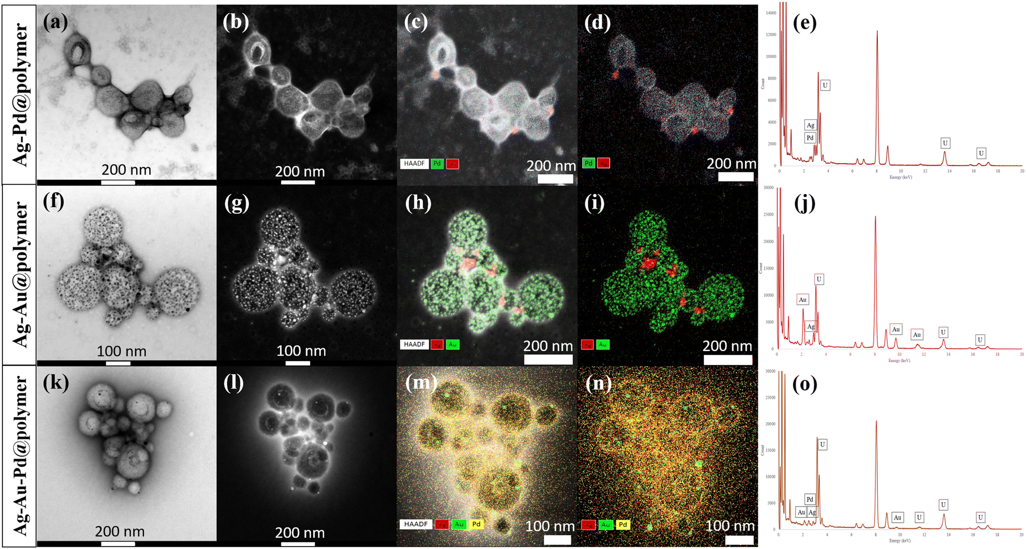 | ||
| Fig. 3 STEM images of Ag–Pd, Ag–Au and Ag–Au–Pd@PEG113-b-PDMAEMA32-b-PHPMA398-CDTPA PMNCs in (a), (f) and (k) bright-field and (b), (g) and (l) HAADF modes. (c), (h) and (m) Overlapped bright-field and STEM-EDX mapping. (d), (i) and (n) STEM-EDX-mapping. (e), (j) and (o) EDX elemental analysis. | ||
Catalyst studies of Au/Ag/Pd@PEG113-b-PDMAEMA32-b-PHPMA398-CDTPA PMNCs
PMNCs exhibit unique catalytic activities through a synergistic effect between the MNPs and the polymer matrix. Their remarkable catalytic performances originate from the presence of large surface areas, where a substantial number of MNPs are located, resulting in a huge number of active sites for reactions to occur. Although the chemical reactions are catalysed only by the MNPs, the polymer matrix does play some important roles in assisting the catalytic mechanism. More specifically, the polymer matrix acts as a form of supporting substrate that provides a stable and controlled environment which helps prevent MNPs from aggregation and maximising their overall catalytic surface area. In addition, the polymer matrix aids in catalyst recyclability and reusability, which is important in showing the good performance of these PMNCs.31,32 Moreover, the polymer matrix in this instance does not impart too much directionality onto the MNPs during ultrasonic reduction unlike conventional capping/stabilising agents, enabling the MNPs to grow to various shapes and sizes. Overall, the polymer matrix did not directly catalyse any chemical reactions presented in this paper; however, it did contribute indirectly by influencing the growth of MNPs on the PMNC surfaces.33In organic chemistry, an important reaction for functional group transformation commonly encountered is the aerobic oxidation of benzyl alcohols catalysed by Au-based catalysts.5,34 In this study, various combinations of Au/Ag/Pd@PEG113-b-PDMAEMA32-b-PHPMA398-CDTPA PMNCs (denoted as Au/Pg/Pd@polymer for simplicity) containing AuNPs were used as catalysts in the aerobic oxidation of 1-phenylethanol to acetophenone, conducted at 80 °C for 2 hours in ultrapure water as a solvent and tert-butyl hydroperoxide (TBHP, tBuOOH) as an oxidation reagent (Table 2). TEM images of the catalyst states before and after subjecting them to this particular organic reaction were obtained using a TEM instrument (Fig. 4), depicting a clear change in the polymeric morphology from vesicles (Fig. 4(a)) to amorphous-like particles with localised concentrations of MNPs (Fig. 4(b)), showing a magnified view of an MNP cluster with an inset d-spacing of 0.214 nm (Fig. 4(c)) for Au-based PMNCs. In the absence of any catalysts, the NMR conversion only reached 2.9% (Table 2, entry 1). Upon changing the catalyst concentration of the Au@polymer from 0.1 to 0.02 (Table 2, entries 2–4), the conversion decreases slightly from 16.5% to 9.3%. In order to achieve a higher conversion value, stepwise growth was performed on the Au@polymer (Table 2, entry 4) until the 4th addition/step (Fig. S14†),5 yielding larger AuNPs and a substantial increase in the starting material conversion to 70.4% (Table 2, entry 5). Interestingly, the catalyst Au–Pd@polymer provided the highest conversion amongst all the other catalyst types at 94.0% (Table 2, entry 8), which far exceeds the conversion even for the catalyst prepared via step-wise growth of AuNPs. A similar phenomenon was observed by Wang et al., where the combination of AuNPs and PdNPs in the same system at a molar ratio of 1:1 generates the highest catalytic activity via more Au/Pd interfaces, which helps increase the overall surface area through the ‘ensemble effect’.35 We then used this knowledge and tested the efficiency of these catalyst systems in a separate coupling reaction.
 | ||
| Fig. 4 TEM images of (a) Au@PEG113-PDMAEMA32-PHPMA400 PMNC before subjecting to organic reactions. After subjecting to catalytic treatment: (b) Magnified view of a MNP cluster with (c) MNP inset d-spacing of 0.214 nm. (d) Amorphous-like particles with (d) MNP inset d-spacing of 0.233 nm and 0.243 nm. (f) Unusual shapes of MNPs with (g) inset d-spacing of 0.218 nm indicating possible Ag–Pd–Au alloy formations. | ||
|
|
|||
|---|---|---|---|
| Entry | Catalyst | Catalyst equiv.a (mol%) | NMR conversionb (%) |
| a Catalyst equiv. (mol%) = [catalyst]/[1-phenylethanol] × 100%. b NMR conversion (%) was calculated based on the 1H NMR spectra of the resulting reaction mixture (Fig. S12†). c Step-wise growth was performed to increase the size of the AuNPs immobilised on the copolymer nanoparticle surfaces up to the 5th step. | |||
| 1 | None | — | 2.9 |
| 2 | Au@polymer | 0.1 | 16.5 |
| 3 | Au@polymer | 0.05 | 13.7 |
| 4 | Au@polymer | 0.02 | 9.3 |
| 5 | Au@polymer (5th step)c | 0.02 | 70.4 |
| 6 | Au@PNVP | 0.02 | 10.5 |
| 7 | Ag–Au@polymer | 0.02 | 61.5 |
| 8 | Au–Pd@polymer | 0.02 | 94.0 |
| 9 | Ag–Au–Pd@polymer | 0.02 | 39.8 |

Pd(0) or catalysts containing PdNPs are widely used in C–C bond formation such as in the Suzuki–Miyaura cross coupling reaction between aryl boronic acids and aryl halides, providing rapid access to sp2–sp2 linkages.36,37 New types of Pd(0) catalysts are being designed constantly, such as direct immobilisation of PdNPs onto various supports such as zeolites,38 silica,39 carbon,40 ligands,41 metal organic frameworks (MOFs),42 and polymers,5,43 In this study, different combinations of Au/Ag/Pd@PEG113-b-PDMAEMA32-b-PHPMA398-CDTPA PMNCs containing PdNPs were used as catalysts in the reaction between 4-iodophenol and phenylboronic acid, with comparisons against Pd@PNVP as a control (Table 3). Similar to a change in catalyst states for the aerobic reaction, a change in morphology was also noticed after subjecting Pd-based PMNCs to cross coupling reactions, where some vesicles fused together with some degree of fragmentation, causing them to be broken down into smaller vesicles or even reverting to simple spheres (Fig. 4(d)) Nevertheless, MNPs remain attached to the surfaces of the resulting polymeric morphologies, which suggests the strong chemisorption interactions between the tertiary amine groups of PDMAEMA and the MNPs. The d-spacings of two randomly chosen MNPs were found to be 0.233 nm and 0.243 nm, which may correspond to either Au or Ag for the former and an alloy for the latter (Fig. 4(e)). Another interesting phenomenon observed was the appearance of more triangular-shaped MNPs (Fig. 4(f)) with a d-spacing of 0.218 nm (Fig. 4(g)), which can also suggest possible Ag–Pd–Au alloy formation. When no catalyst was added to the reaction mixture, the final product conversion only reached 10.1% after 1 hour. At a catalyst concentration of 0.02 mol%, all catalysts were found to exhibit high conversions of over 95% (Table 3, entries 2–4 and 6) except for the catalyst Au–Pd@polymer which only showed a conversion of 68.1% (Table 3, entry 5). The concentrations of all catalysts were then reduced to 0.01 mol% (Table 3, entries 7–11) and subsequently to 0.005 mol% (Table 3, entries 12–16) to understand their performances at reduced concentration levels. The conversions obtained for Pd@PNVP, the Pd@polymer and the Ag–Pd@polymer are ranked the highest among all the catalysts for all catalyst concentrations with little deviations from one another, with the Ag–Pd@polymer displaying slightly higher conversion values of 98.5% at a catalyst concentration of 0.02 mol% (Table 3, entry 4) and 79.0% at 0.005 mol% (Table 3, entry 14). A similar phenomenon was observed by Kimber et al., where a biosynthetic Pd/Ag, termed bio-Pd/Ag, nanoparticle catalyst, produced from the metal-reducing bacterium Shewanella oneidensis, showed enhanced Suzuki–Miyaura cross coupling reaction activity, reaching high conversion values within just 2 hours of reaction time.44 The catalyst Au–Pd@polymer consistently displayed poor performance in conversions even at a catalyst concentration of 0.02 mol%, which decreases to 63.8% at 0.01 mol% (Table 3, entry 10) and then to 55.2% at 0.005 mol% (Table 3, entry 15). A possible reason for this observation could be that the interaction between AuNPs and PdNPs did not favour the coupling reaction due to lower stability and less uniformity in the entire structure.45 The ultrasound-assisted reduction process caused all metal salts in the mixture to be reduced at almost the same time, creating an ill-defined metal structural surface, which can be difficult to discern and analyse. Therefore, there exist more exposed Au surfaces than Pd MNP surfaces in the Au–Pd@polymer catalyst system which can limit reactant conversions.
|
|
|||
|---|---|---|---|
| Entry | Catalyst | Catalyst equiv.a (mol%) |
NMR conversionb (%) |
| a Catalyst equiv. (mol%) = [catalyst]/[4-iodophenol] × 100%. b NMR conversion (%) was calculated based on the 1H NMR spectra of the resulting reaction mixture (Fig. S13†). | |||
| 1 | None | — | 10.1 |
| 2 | Pd@PNVP | 0.02 | 97.5 |
| 3 | Pd@polymer | 0.02 | 97.3 |
| 4 | Ag–Pd@polymer | 0.02 | 98.5 |
| 5 | Au–Pd@polymer | 0.02 | 68.1 |
| 6 | Ag–Au–Pd@polymer | 0.02 | 96.0 |
| 7 | Pd@PNVP | 0.01 | 95.1 |
| 8 | Pd@polymer | 0.01 | 92.8 |
| 9 | Ag–Pd@polymer | 0.01 | 92.0 |
| 10 | Au–Pd@polymer | 0.01 | 63.8 |
| 11 | Ag–Au–Pd@polymer | 0.01 | 83.7 |
| 12 | Pd@PNVP | 0.005 | 72.0 |
| 13 | Pd@polymer | 0.005 | 77.4 |
| 14 | Ag–Pd@polymer | 0.005 | 79.0 |
| 15 | Au–Pd@polymer | 0.005 | 55.2 |
| 16 | Ag–Au–Pd@polymer | 0.005 | 76.0 |

The Suzuki–Miyaura cross-coupling reaction to synthesise 4-phenylphenol from 4-iodophenol and phenylboronic acid was followed every 10 minutes until 60 minutes from the start of the reaction, and the NMR conversion values were plotted (Fig. 5(a)). Pd@PNVP and the Ag–Pd@polymer reached relatively high conversions of over 90% within 20 minutes of the reaction, with the Pd@polymer and Ag–Au–Pd@polymer achieving the same conversion within 30 minutes. The Au–Pd@polymer achieved approximately 70% conversion after 60 minutes, with a slow increase in starting material conversion throughout the entire kinetic study. The reusability of these catalysts was also plotted with the first addition of starting materials termed ‘reuse batch 1’, and subsequently 4 other batches of starting materials containing the same amounts were added with a 1 hour reaction time interval to produce results for ‘reuse batch 2’ to ‘reuse batch 5’ (Fig. 5(b)). Based on the NMR conversion values for all catalysts, the performance of Pd@PNVP, the Pd@polymer and the Ag–Pd@polymer decreases gradually from 94.6%, 98.5% and 96.0%, respectively, in ‘reuse batch 1’ to 82.8%, 80.1% and 80.5% in ‘reuse batch 5’ with little deviation from one another, whilst the performance of the Ag–Au–Pd@polymer decreases at a higher rate from 91.5% to 73.8%. The performance of the Au–Pd@polymer consistently showed poor performance comparatively from 65.5% in ‘reuse batch 1’ to 51.2% in ‘reuse batch 5’, which is in good agreement with previous data obtained (Table 3). An interesting trend observed for all catalysts is that the rate of performance drop gradually slows down upon repeated usage, which can suggest the good reusability of these catalysts beyond 5 times with minimum effects on the overall conversion values.
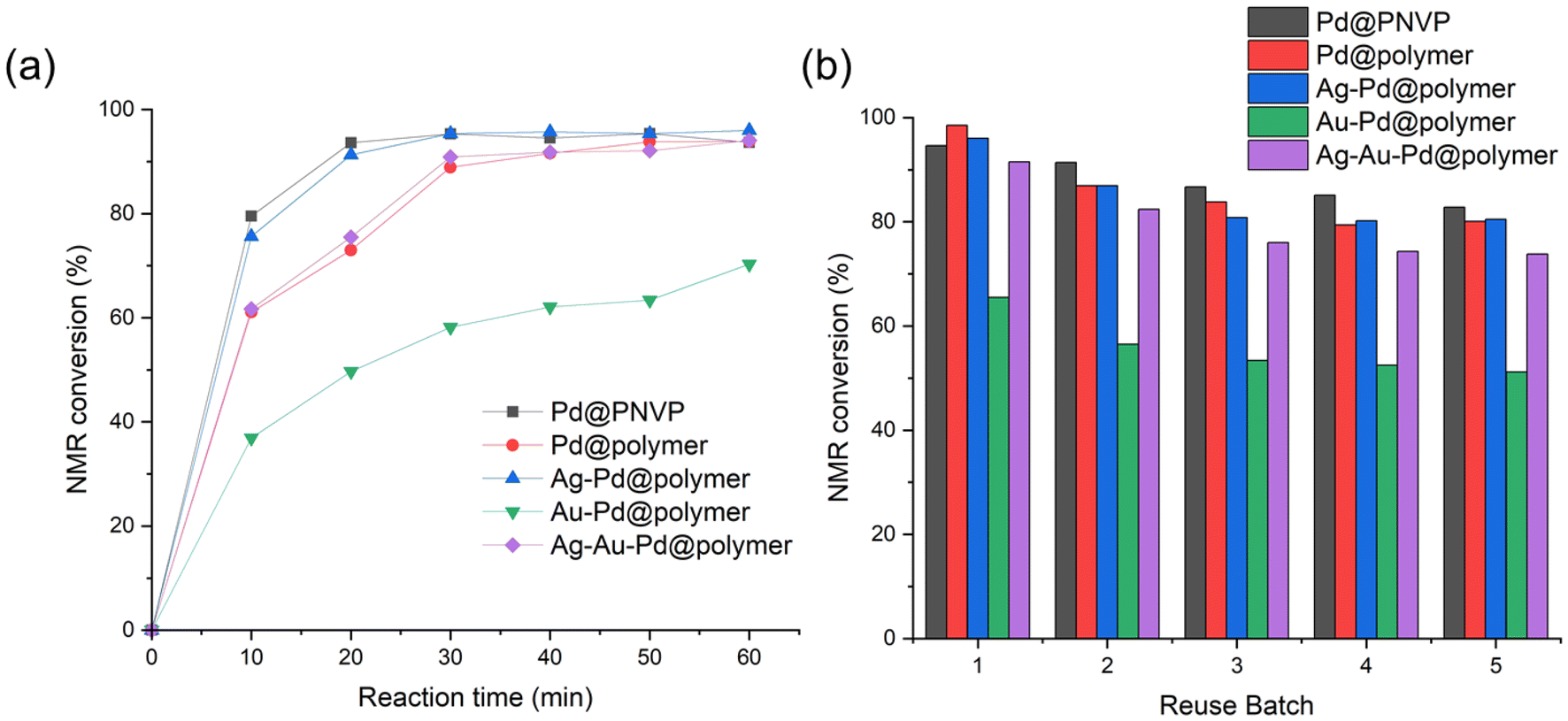 | ||
| Fig. 5 (a) Time-dependent NMR conversion graph taken every 10 minutes for 60 minutes and (b) reusability test NMR conversion graph plotted by counting from the first to the fifth reuse batch, for different combinations of Au/Ag/Pd@PEG113-b-PDMAEMA32-b-PHPMA398-CDTPA PMNCs. | ||
Conclusion
Thermally-initiated RAFT-PISA combined with ultrasound, as a way to reduce metal salts into their corresponding MNPs, has proved to be useful in preparing PMNCs for catalytic studies. Morphological transformations can be seen upon increasing the DP of the PHPMA block starting from simple spheres to complex fused multi-compartmental vesicles with a fibre-like structure. The use of ultrasound to produce MNPs in ultrapure water as a solvent provided a relatively “green” method without the use of any external chemical reductants. Given the small sizes of all MNPs synthesised in this manner, PMNCs are attractive candidates for catalytic applications such as heterogeneous phase catalysis of aerobic alcohol oxidation and the Suzuki–Miyaura cross-coupling reaction. Interestingly, the different combinations of Au/Ag/Pd@PEG113-b-PDMAEMA32-b-PHPMA398-CDTPA PMNCs showed a dependence between MNP types and catalytic performances with Ag–Pd@PEG113-b-PDMAEMA32-b-PHPMA398-CDTPA being the best catalyst for the coupling reaction between 4-iodophenol and phenylboronic acid, while Au–Pd@PEG113-b-PDMAEMA32-b-PHPMA398-CDTPA is the best catalyst for the aerobic oxidation of 1-phenylethanol to acetophenone. This study helps in opening up more avenues for the heterogeneous catalysis of organic reactions, which can also help expand the usefulness of ultrasound and thermal-RAFT-PISA as scalable options in preparing complex PMNCs. Future work will involve crosslinking the PHPMA core with a crosslinking agent to resist organic solvents, allowing these PMNCs to react in organic solvents as well. A systematic study of the relationship between the polymer morphology and catalysis performance can also be carried out to gain a deeper understanding of these types of systems.Data availability
The data supporting this article have been included as part of the ESI.†Conflicts of interest
There are no conflicts of interest to declare.Acknowledgements
N. K. S. T. thanks Monash University for the MGS and DIPRS scholarships. All authors involved in this work acknowledge the Monash Centre for Electron Microscopy (MCEM) for permissions pertaining to the use of their facilities. The authors express their gratitude to Dr Jing Wan and Dr Bo Fan of Monash University, School of Chemistry, for their advice and discussions in this project. The authors also wish to express their thanks to Dr Tim Williams, Dr Emily Chen and Dr Laura Yin for their guidance on (HR)-TEM imaging, STEM imaging, and STEM-EDX mapping. S. H. T. is thankful for the support from the ARC Centre of Excellence for Enabling Eco-Efficient Beneficiation of Minerals (Grant No. CE200100009).References
- V. V. Mody, R. Siwale, A. Singh and H. R. Mody, J. Pharm. BioAllied Sci., 2010, 2, 282–289 CrossRef CAS PubMed.
- E. M. Materón, C. M. Miyazaki, O. Carr, N. Joshi, P. H. S. Picciani, C. J. Dalmaschio, F. Davis and F. M. Shimizu, Appl. Surf. Sci., 2021, 6, 100163 CrossRef.
- Y. S. Kang, S. Risbud, J. F. Rabolt and P. Stroeve, Chem. Mater., 1996, 8, 2209–2211 CrossRef CAS.
- S. Rudge, C. Peterson, C. Vessely, J. Koda, S. Stevens and L. Catterall, J. Controlled Release, 2001, 74, 335–340 CrossRef CAS PubMed.
- J. Wan, B. Fan and S. H. Thang, Nanoscale Adv., 2021, 3, 3306–3315 RSC.
- M. J. Ndolomingo, N. Bingwa and R. Meijboom, J. Mater. Sci., 2020, 55, 6195–6241 CrossRef CAS.
- N. Suzuki, N. Ebara, R. Arai, C. Takahashi, T.-Y. Hung, Y. Takeoka, M. Rikukawa, Y. Yokota and F.-Y. Tsai, Catal. Sci. Technol., 2025, 15, 696–707 RSC.
- S. Pedroso-Santana and N. Fleitas-Salazar, Part. Syst. Charact., 2022, 40, 2200146 Search PubMed.
- P. N. Eyimegwu, J. A. Lartey and J.-H. Kim, ACS Appl. Nano Mater., 2019, 2, 6057–6066 CrossRef CAS.
- Y. Zare and I. Shabani, Mater. Sci. Eng., C, 2016, 60, 195–203 CAS.
- Z. Deng and S. Liu, Polymer, 2020, 207, 122914 CAS.
- N. J. W. Penfold, J. Yeow, C. Boyer and S. P. Armes, ACS Macro Lett., 2019, 8, 1029–1054 CAS.
- P. Lim Soo and A. Eisenberg, J. Polym. Sci., Part B: Polym. Phys., 2004, 42, 923–938 Search PubMed.
- B. Fan, R. E. Yardley, J. F. Trant, A. Borecki and E. R. Gillies, Polym. Chem., 2018, 9, 2601–2610 CAS.
- J. Wan, B. Fan, Y. Liu, T. Hsia, K. Qin, T. Junkers, B. M. Teo and S. H. Thang, Polym. Chem., 2020, 11, 3564–3572 CAS.
- J. Wan, B. Fan and S. H. Thang, Chem. Sci., 2022, 13, 4192–4224 CAS.
- N. Toshima, Metal Nanoparticles for Catalysis, in Nanoscale Materials, ed. L. M. Liz-Marzán and P. V. Kamat, Springer, Boston, MA., 2004, pp. 79–96 Search PubMed.
- Z. Alinejad, F. Khakzad and A. R. Mahdavian, Eur. Polym. J., 2018, 104, 106–114 CAS.
- Y. Li, Y. Wu, Q. Xu, Y. Gao, G. Cao, Z. Meng and C. Yang, Polym. Chem., 2013, 4, 4655–4662 CAS.
- M. V. Prud, A. Kyrychenko and O. N. Kalugin, J. Phys. Chem. C, 2023, 127, 11748–11759 CAS.
- G. Sharma, D. Kumar, A. Kumar, A. H. Al-Muhtaseb, D. Pathania, M. Naushad and G. T. Mola, Mater. Sci. Eng., C, 2017, 71, 1216–1230 CAS.
- J. W. M. Crawley, I. E. Gow, N. Lawes, I. Kowalec, L. Kabalan, C. R. A. Catlow, A. J. Logsdail, S. H. Taylor, N. F. Dummer and G. J. Hutchings, Chem. Rev., 2022, 122, 6795–6849 CAS.
- H. B. Ahmed and H. E. Emam, J. Mol. Liq., 2019, 287, 110975 CAS.
- C. Dwivedi, A. Chaudhary, S. Srinivasan and C. K. Nandi, Colloids Interface Sci. Commun., 2018, 24, 62–67 CAS.
- J. D. S. Newman and G. J. Blanchard, Langmuir, 2006, 22, 5882–5887 CrossRef CAS PubMed.
- E. Filippo, A. Serra, A. Buccolieri and D. Manno, Colloids Surf., A, 2013, 417, 10–17 CrossRef CAS.
- J.-J. Yuan, A. Schmid, S. P. Armes and A. L. Lewis, Langmuir, 2006, 22, 11022–11027 CrossRef CAS PubMed.
- A. Rostek, M. Breisch, K. Pappert, K. Loza, M. Heggen, M. Koller, C. Sengstock and M. Epple, Beilstein J. Nanotechnol., 2018, 9, 2763–2774 CrossRef CAS PubMed.
- A. Rostek, K. Loza, M. Heggen and M. Epple, RSC Adv., 2019, 9, 26628–26636 RSC.
- M. H. Ali, M. A. K. Azad, K. A. Khan, M. O. Rahman, U. Chakma and A. Kumer, ACS Omega, 2023, 8, 28133–28142 CrossRef CAS PubMed.
- B. P. S. Chauhan, J. S. Rathore and T. Bandoo, J. Am. Chem. Soc., 2004, 126, 8493–8500 CrossRef CAS PubMed.
- S. Patra, S. Mishra, B. Parhi, H. Mishra and S. K. Swain, Results Chem., 2023, 6, 101172 CrossRef CAS.
- Z. B. Shifrina, V. G. Matveeva and L. M. Bronstein, Chem. Rev., 2020, 120, 1350–1396 CrossRef CAS PubMed.
- S. A. C. Carabineiro, A. P. C. Ribeiro, J. G. Buijnsters, M. Avalos-Borja, A. J. L. Pombeiro, J. L. Figueiredo and L. M. D. R. S. Martins, Catal. Today, 2020, 357, 22–31 CrossRef CAS.
- J. B. Chang, C. H. Liu, J. Liu, Y. Y. Zhou, X. Gao and S. D. Wang, Nanomicro. Lett., 2015, 7, 307–315 CAS.
- S. E. Hooshmand, B. Heidari, R. Sedghi and R. S. Varma, Green Chem., 2019, 21, 381–405 RSC.
- B. Cornelio, A. R. Saunders, W. A. Solomonsz, M. Laronze-Cochard, A. Fontana, J. Sapi, A. N. Khlobystov and G. A. Rance, J. Mater. Chem. A, 2015, 3, 3918–3927 Search PubMed.
- B. Zawadzki, E. Kowalewski, M. Asztemborska, K. Matus, S. Casale, S. Dzwigaj and A. Śrębowata, Catal. Commun., 2020, 145, 106113 CrossRef CAS.
- S. Paul and J. H. Clark, J. Mol. Catal. A: Chem., 2004, 215, 107–111 Search PubMed.
- H. F. Huo, D. Liu, A. Bao, T. Muschin, C. Bai and Y. S. Bao, ACS Omega, 2022, 7, 12779–12786 CrossRef CAS PubMed.
- R. Martin and S. L. Buchwald, Acc. Chem. Res., 2008, 41, 1461–1473 CrossRef CAS PubMed.
- S. Luo, Z. Zeng, G. Zeng, Z. Liu, R. Xiao, M. Chen, L. Tang, W. Tang, C. Lai, M. Cheng, B. Shao, Q. Liang, H. Wang and D. Jiang, ACS Appl. Mater. Interfaces, 2019, 11, 32579–32598 Search PubMed.
- J. Wang, Y. Ge, Y. Wang, R. Sun, X. Yang, H. Xue, X. Ma, J. Liu and K. Hu, Eur. Polym. J., 2024, 202, 112650 Search PubMed.
- R. L. Kimber, F. Parmeggiani, T. S. Neill, M. L. Merroun, G. Goodlet, N. A. Powell, N. J. Turner and J. R. Lloyd, Microb. Biotechnol., 2021, 14, 2435–2447 CrossRef CAS PubMed.
- G. D. Kalita, P. P. Sarmah, G. Kalita and P. Das, Nanoscale Adv., 2021, 3, 5399–5416 RSC.
Footnote |
| † Electronic supplementary information (ESI) available: Experimental details, 1H NMR, 13C NMR spectra, GPC curves and additional TEM images. See DOI: https://doi.org/10.1039/d5py00113g |
| This journal is © The Royal Society of Chemistry 2025 |