Manipulating defects simultaneously boosts the crystal stability and the electrochemical reversibility toward long-life aqueous zinc ion batteries†
Shuyue
Hou
a,
Xinyue
Chen
a,
Gangguo
He
a,
Xin
Peng
a,
Jingjing
Wang
a,
Can
Huang
a,
Huan
Liu
c,
Tiezhong
Liu
a,
Xin
Wang
b,
Lingzhi
Zhao
 *a and
Shuang
Hou
 *a
*a
aGuangdong Provincial Engineering Technology Research Center for Low Carbon and Advanced Energy Materials, Guangdong Provincial Key Laboratory of Chip and Integration Technology, School of Semiconductor Science and Technology, South China Normal University, Foshan 528225, China. E-mail: shou@m.scnu.edu.cn; lzzhao@scnu.edu.cn
bInstitute of Carbon Neutrality, Zhejiang Wanli University, Ningbo 315100, China
cGuangdong Haomei New Materials Co., Ltd, Qingyuan, 511540, China
First published on 23rd November 2024
Abstract
A great deal of attention has been paid to vanadium-based materials as promising cathode candidates for aqueous zinc ion batteries (AZIBs) due to their excellent theoretical capacity. However, the strong interactions among Zn2+, H2O and vanadium-based cathodes easily trigger the irreversible dissolution and structure collapse of vanadium, especially at low current density. To address these problems, defect engineering of sulfur doping (point defect) and heterojunction formation (interface defect) is reported herein for designing a robust S-VO2/V6O13 (SVO) cathode via a one-step sulfurization. SVO could not only restrict the formation of inactive by-products originating from irreversible dissolution, but also boost the reaction reversibility and kinetics of Zn2+ and H+, simultaneously solving the major questions of capacity degradation. As a result, a series of spectroscopic and theoretical studies verified that SVO-2 possesses a stable crystal structure and manifests excellent Zn2+ and H+ storage performance at both low and high current densities. Specifically, a high capacity retention rate of 85.8% can be achieved with a specific capacity of 416 mA h g−1 after 500 cycles at 0.5 A g−1. Even at 10 A g−1, the specific capacity reaches 252 mA h g−1 after 3000 cycles. This work highlights a practical strategy for designing long-term electrodes with great reliability for aqueous batteries.
1. Introduction
Rechargeable aqueous zinc ion batteries (AZIBs) are an emerging energy storage system with the advantages of feasible fabrication, environmental benignity and high safety.1,2 Vanadium-based oxides are promising cathode materials for AZIBs due to their wide valence range (V5+ to V3+), rich crystal structure and high specific capacity.3,4 However, vanadium-based cathodes exhibit severe capacity degradation at low current densities, and the related review shows that 80% capacity retention at 0.5 A g−1 can only be achieved with limited cycle numbers (<60 cycles), which severely limits their development and application.5 The fundamental reason is the poor stability of the crystal structure, so it is not only difficult for a vanadium-based cathode to withstand the mechanical strain brought about by the deep embedding and slow diffusion of Zn2+ and then structural collapse, but it also has a thermodynamic tendency to severely dissolve in the aqueous electrolyte.6 Worse still, the dissolved ions further generate the inactive byproduct Zn3V2O7(OH)2·2H2O (ZVOH) to cover the electrode surface, hindering the interfacial transport of Zn2+.7,8 Therefore, based on the above inferences, the key for a vanadium-based cathode achieving high capacity retention at low current density is to improve its structural stability and the diffusion rate of Zn2+.As revealed by the previous reports, introducing defects, such as point defects and interface defects, can directly affect the inherent properties of vanadium oxides, thus fundamentally changing thermodynamic stability and reaction kinetics.9–11 Different defects with various effects confer more chances to design robust vanadium oxides. Specifically, for point defects, heteroatom doping strategies can mainly enhance the conductivity of the material and provide more active sites. For interface defects, constructing a heterojunction structure can form a built-in electric field to eliminate the original band gap, and the aperiodic lattice arrangement to provide extra space for ion diffusion and storage buffering the generated stress.12–17 Regrettably, although the specific capacity and cycle life are improved at high current densities, the capacity degradation of vanadium oxide cathodes at low current densities remains severe.18,19 For example, the reported S doping vanadium-based cathode cycle life at low current density is in fact far from satisfactory and cannot exceed 100 cycles.6,20,21 Apparently, it is restricted to individually use the above defect to enhance the capacity retention rate of vanadium-based cathodes at low current density. Therefore, exploring effective defect engineering techniques is critically necessary.
Herein, we intend to design a material with a combination of point defects (sulfur doping) and interface defects (VO2/V6O13) by one-step sulfurization. Our DFT calculations disclose that the formation energy of S-VO2/V6O13 is significantly reduced, which inhibits static dissolution, collapse, and buildup of irreversible byproducts during cycling. Moreover, the density of electronic states of S-VO2/V6O13 is fundamentally changed with conductor properties and the diffusion barrier of Zn2+ in the material is also greatly reduced, improving the electrochemical reversibility in the cycling process. The advantages of manipulating doping and heterojunction engineering are shown in Fig. 1. When S-VO2/V6O13 is used as the cathode, it shows excellent cycle stability and high reversibility. After 500 cycles at 0.5 A g−1 (corresponding to 890 h), S-VO2/V6O13 still displays a specific capacity of 416 mA h g−1, and the capacity retention rate is as high as 85.8%. Correspondingly, in situ XRD and XRD results after 100 cycles fully prove the stability of S-VO2/V6O13 in the electrochemical reaction and the reversible formation of by-products. This work will inspire the development of other vanadium-based cathodes with outstanding cycling stability via intentional defect engineering.
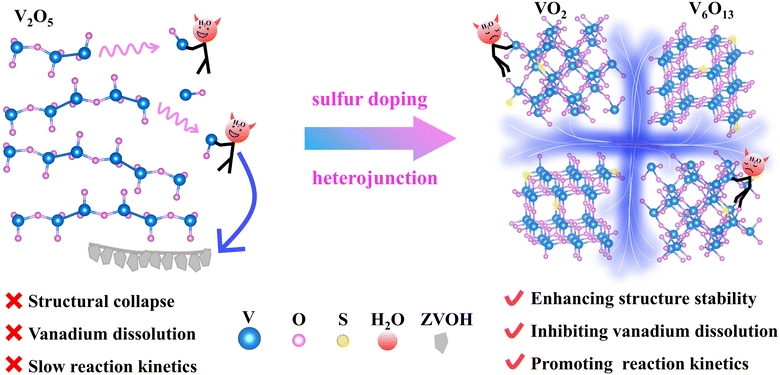 | ||
| Fig. 1 Schematic of solving the capacity degradation problem by means of a combination of sulfur doping and heterojunctions. | ||
2 Results and discussion
2.1 Structure and morphology characterization
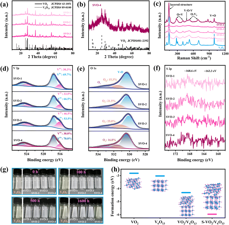
The crystal structure of all samples was characterized by XRD. First, the phase of V2O5 after the sol–gel and calcination process remains unchanged (Fig. S1a†), but its (001) crystal face strength is weakened and (110) has the highest strength. With the increase in sulfur vapor concentration, the products obtained by the reduction reaction of V2O5 are named SVO-1 to 4 in turn. From the XRD curves displayed in Fig. 2a, all the peaks of SVO-1, SVO-2 and SVO-3 match well with those of monoclinic VO2 (JCPDS#43-1051) and monoclinic V6O13 (JCPDS#89-0100), proving the successful synthesis of the intended heterojunction structure. When the mass of sulfur powder is consistent with V2O5 (SVO-4), the XRD spectrum of the sample (Fig. 2b) is only assigned to VO2 (JCPDS#81-2392) due to the easy phase transitions of metastable V6O13, and its low signal intensity shows poor crystallinity, probably due to the excessive reduction reaction. As displayed in the Raman spectrum in Fig. 2c, all samples show the same peaks at 140, 193, 280, 303, 404, 485, 519, 695 and 992 cm−1, which demonstrates similar structural units.22–24 It is worth noting that single-phase V2O5 and SVO-4 have a narrower FWHM and higher peak intensity, while other SVOs with heterojunction interfaces have a wider FWHM and weaker peak intensity. These results prove that there are irregular V–O bond arrangements due to the abundant heterojunction interfaces.The elemental valence and bonding states of the samples were further determined by XPS. As shown in Fig. 2d, the vanadium element of SVO samples shows a mixed state of V5+ and V4+ (517.5 and 252.1 eV, 516.1 and 523.7 eV).25,26 The O 1s XPS spectra displayed in Fig. 2e can be deconvoluted into three peaks resulting from lattice oxygen (OL, 530.3 eV), oxygen vacancies (OV, 531.5 eV), and chemically adsorbed oxygen or crystalline water molecules (OC, 533.3 eV).27 The proportion of V4+ and OV simultaneously increases with the increased mass of sulfur powder, which indicates that the reduction reaction is continuously enhanced. Specifically, V5+ still dominates in SVO-4 probably because the excessive low-valence vanadium on the surface is easily oxidized into the highest state as indicated by previous studies.25,28 The XPS spectrum of the precursor V2O5 is shown in Fig. S1b,† presenting a mixed distribution of V5+ and V4+ as well. Besides, from S 1s (Fig. 2f), the weak peaks at around 168.6 eV (S4+) and 163.3 eV (S2−) can be observed, and the ICP results (Table S1†) indicate that the mass percentage of sulfur atoms in all four SVO samples is around 0.1%, proving the successful doping of sulfur atoms.6,29
In order to explore the stability of the SVO material in aqueous electrolyte, a static immersion experiment was carried out. In detail, 0.02 g sample was immersed in 10 mL deionized water and the color changes in optical images at different intervals were recorded. As is well known, vanadium-based oxides are slightly soluble in water and generate a series of different ions that are mostly yellow in color.30,31 As for V2O5, it will react with H2O to generate VO2(OH)2−.30 VO2(OH)2− further reacts with Zn2+ in the electrolyte to generate inactive Zn3V2O7(OH)2·2H2O (ZVOH), and the reaction equation is as follows:
| V2O5 + 3H2O = 2VO2(OH)2− + 2H+ | (1) |
| 2VO2(OH)2− + 3Zn2+ + 3H2O = Zn3V2O7(OH)2·2H2O + 4H+ | (2) |
Such a spontaneous irreversible reaction is unfavorable, and the remaining H+ will reduce the pH value of the electrolyte, which will lead to corrosion of the zinc anode and shorten the battery life. The experimental results in Fig. 2g show that the solution with V2O5 turns pale yellow which gradually darkens within 5 h to 100 h, while the solution with SVO-4 turns pale yellow after 500 h. In sharp contrast, the solutions with SVO-1, SVO-2 and SVO-3 are still colorless after 1600 h, suggesting that the combined effect of sulfur atom doping and heterojunctions can significantly inhibit the dissolution of vanadium. Meanwhile, the formation energies (Ef) of VO2, V6O13, the heterojunction (VO2/V6O13) and the sulfur-doped heterojunction (S-VO2/V6O13) are calculated as shown in Fig. 2h. Ef (VO2/V6O13) is −4.307 eV significantly lower than that of two single phases and it is further sharply reduced to −5.966 eV when a sulfur atom is introduced. This indicates that the combination of sulfur doping and heterojunctions enables a more robust crystal structure compared to single modification engineering. This simulation result is consistent with the soaking experiment results.
Furthermore, SEM was used to explore the morphology of different samples. After the sol–gel and calcination process, the surface of commercial micro block V2O5 transforms from a ∼200 nm thick plate into a loosely stacked small particle of ∼50 nm (Fig. S2a and b†) that facilitates the subsequent sulfurization reaction. As shown in Fig. 3a, the surface of SVO-2 is composed of nano-plates with grooves, showing a similar morphology to SVO-1. But when the mass of sulfur powder increases, the grooves of SVO-3 on the surface and the plate shape of SVO-4 all disappear (Fig. S2†). The TEM result of Fig. 3b also indicates the micro size of SVO-2, which is consistent with the SEM results (Fig. 3a). As shown in Fig. 3c, the HRTEM image of SVO-2 clearly manifests the heterojunction interface. Simultaneously, the crystal spacing of 0.32 and 0.33 nm calculated from the IFFT diagram (Fig. 3d) correspond to the (011) crystal plane of VO2 and the (003) crystal plane of V6O13, respectively. The (011) crystal plane of VO2 and the (−603), (005) and (−401) crystal planes of V6O13 are also detected in the SAED diagram of SVO-2 (Fig. 3e). These results indicate the successful formation of a VO2/V6O13 heterojunction structure. The energy dispersive X-ray spectrum (EDS) of the synthesized SVO-2 shows that the elements V, O and S are uniformly distributed in the sample (Fig. 3f).
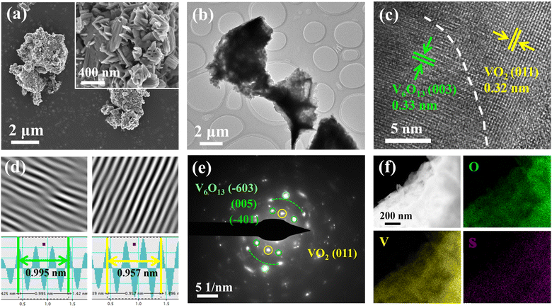 | ||
| Fig. 3 Morphological and structural characterization of SVO-2. (a) SEM images; (b) TEM image; (c) HRTEM image and (d) IFFT patterns; (e) the corresponding SAED image; (f) EDS images. | ||
2.2 Electrochemical performance and kinetics analysis
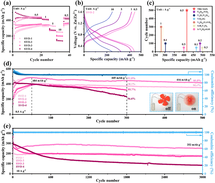
To evaluate the electrochemical performance of V2O5 and SVO as cathodes for AZIBs, coin cells were assembled with Zn metal foil as the anode and 2 M Zn(CF3SO3)2 aqueous solution with 0.07 M sodium dodecyl sulfate additive as the electrolyte. Fig. 4a displays the rate performance of SVO. In the first 20 cycles at 0.5 A g−1, the capacity increases continuously due to the increase in exposed surface area and active sites during the intercalation/de-intercalation of Zn2+.19,32 After 20 cycles of pre-activation, the heterostructure SVO shows a satisfactory rate performance, in which the average specific discharge capacity of SVO-2 is 440, 420, 330 and 250 mA h g−1 at 0.5, 1, 5 and 10 A g−1. The corresponding GCD curve is shown in Fig. 4b.At low current density, the capacity of SVO-2 remained at 416 mA h g−1 after 500 cycles, showing a very competitive specific capacity and cycle life among similar classes of vanadium-based oxides, as shown in Fig. 4c.6,14,15,18,20,33 Detailed cycling performance data for SVO are shown in Fig. 4d. After the 50 cycle activation, the highest specific capacity of SVO-2 is 484 mA h g−1. The specific capacity is maintained at 416 mA h g−1 with a high capacity retention rate of 85.5% after 500 cycles, showing long-term cycle stability. Meanwhile, the capacity retention rate of SVO-1 is also as high as 86.4% after 500 cycles. However, when the degree of sulfur reduction increases, the cycle stability of cathode materials decreases. After 300 charge/discharge cycles, the capacity retention rate of single-phase SVO-4 is only 56.6%. The inset of Fig. 4d shows a rotating fan powered by full cells with a SVO-2 cathode. In addition, the cycle performance at high current density determines the potential of the battery in fast charging application. At 10 A g−1, SVO-2 can still provide a high capacity of 252 mA h g−1 after 3000 cycles, while the specific capacity of single-phase SVO-4 drops rapidly in the first 500 cycles (Fig. 4e) and the capacity of precursor V2O5 also decreases sharply after 200 cycles of activation (Fig. S3†). Even at a mass loading of over 10 mg cm−2 (Fig. S4†), high capacities of 330 and 242 mA h g−1 can be obtained at 0.5 and 3 A g−1, respectively. Apparently, the improvement of long-cycle stability is closely related to defect manipulation of the heterostructure and sulfur atom doping. The disordered atoms in the aboundant heterojunction interface of SVO could provide more reaction sites for electrochemical reactions and relieve the mechanical stress caused by Zn2+ intercalation/deintercalation. These advantages should greatly increase the specific capacity and cycling stability of AZIBs.33,34
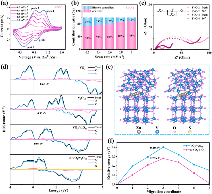
In order to explain the excellent electrochemical performance of SVO-2, the reaction kinetics were analyzed by experiments and theoretical calculation in detail. Fig. 5a displays the CV curves with various scan rates from 0.2 to 1.0 mV s−1, and the relationship between the peak current (i, mA) and scan rate (v, mV s−1) can be described by using the equation i = avb or log(i) = b × log(v) + log(a), where a and b are adjustable parameters. The calculated b values of the SVO-2 electrode are 1.12, 0.96, 0.87 and 1.14 (Fig. S5a†), suggesting that pseudo-capacitance plays an important role in the electrochemical process of the SVO-2 electrode.28 The capacitive contributions can be calculated as i = k1v + k2v1/2, where k1 and k2 are constants, and k1v represents the capacitive contribution. Correspondingly, the calculated results shown in Fig. 5b and S5b† indicate that the capacitance contribution of SVO-2 represented by the blue area is 73% at 0.2 mV s−1 and increases to 88% at 1.0 mV s−1, thus conferring its excellent rate performance. Meanwhile, Fig. S6† displays the b value of SVO-1, SVO-3 and SVO-4. By contrast, the b value of SVO-4 is lower, which indicates its relatively low pseudo-capacitance that results in poor rate performance.
The in situ electrochemical impedance spectroscopy (EIS) measurement was conducted to further investigate the kinetics states of Zn2+. In the Nyquist plots in Fig. 5c, the high frequency region corresponds to a semicircle and its radius represents the charge transfer resistance (Rct) between the electrode and electrolyte. After 50 cycles, the Rct of SVO-2 and SVO-4 decreased due to the material activation,35 the Rct of SVO-2 decreased from 74 Ω to 12 Ω, while that of SVO-4 decreased to 21 Ω, demonstrating that the combination of heterojunctions and doping could effectively enhance the conductivity of the material. The DFT calculations further confirm the synergistic effect of sulfur doping and the heterostructure on the electrochemical properties. Fig. 5d shows the electron density diagrams of VO2, V6O13, VO2/V6O13 and S-VO2/V6O13 in turn. The band gap of VO2/V6O13 (0.07 eV) is smaller than that of VO2 (0.65 eV) and V6O13 (0.33 eV). Importantly, the band gap of S-VO2/V6O13 disappears, which shows that its conductivity is largely improved by introducing sulfur atom doping to the heterojunction structure, corresponding to the EIS results. Furthermore, the possible diffusion paths of Zn2+ in VO2/V6O13 and S-VO2/V6O13 are investigated (Fig. 5e), and the corresponding diffusion barriers are shown in Fig. 5f. The diffusion energy barrier of Zn2+ in S-VO2/V6O13 is 0.28 eV, which is much lower than the 0.40 eV in VO2/V6O13. The calculation results show that manipulating defects can reduce the electrostatic repulsion between Zn2+ and cathode materials, significantly improving the ion diffusion kinetics.
2.3 Charge storage mechanism and structural evolution of SVO-2
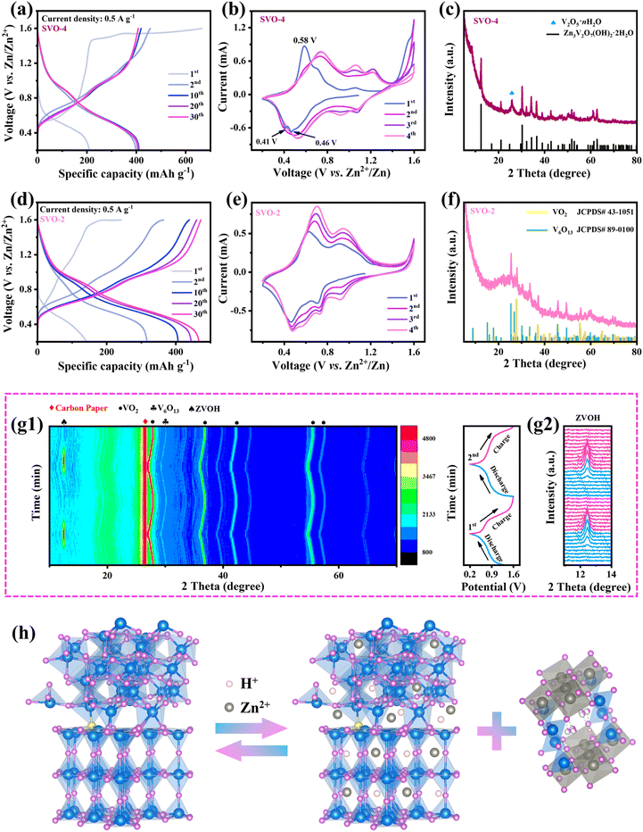
The combined effect of SVO-2 on the charge storage mechanism and structural evolution was comprehensively investigated. First, there are obvious differences between SVO-4 and SVO-2 in the initial charge curves. As shown in Fig. 6a, when the SVO-4 electrode was first charged, a continuous charging platform appeared at 1.45–1.6 V, which was caused by the oxidation of VO2 and the severe oxygen evolution reaction due to the excellent conductivity of the SVO-4 electrode.36,37 The CV curves also display a sharp current increase at around 1.4–1.6 V, which is consistent with the GCD curves (Fig. 6b). In the subsequent cycles, the oxidation peak at 0.58 V and the reduction peaks at 0.41 and 0.46 V in the first CV curve disappeared and the CV curves were highly consistent. These results indicate that SVO-4 underwent an irreversible phase transition during the first charge. This generated new phase would contribute a certain capacity during the electrochemical reaction.38,39 It is worth noting that the oxidation process of low-valent vanadium at ∼1.6 V also exists in SVO-2, but this process is not obvious (Fig. 6d). This may be due to the activation of the exposed low-valent vanadium atoms in a small amount. Interestingly, the CV curve of SVO-2 in the first cycle (Fig. 6e) is almost the same as the subsequent cycle curve, which indicates that the first cycle reaction is completely reversible, and the continuous charging at 1.6 V does not generate a new phase. The peaks of the CV curve correspond to the multi-step reactions among V4+/V3+ and V5+/V4+.40 Moreover, due to the material activation, the redox peak current gradually increases in the cycle.41 Fig. S7† shows GCD curves and CV curves of V2O5, SVO-1 and SVO-3. Because V5+ in V2O5 is the highest valence state, thus there is no oxidation platform at around 1.6 V in the curve. However, SVO-1 and SVO-3 show a very similar phenomenon where the first oxidation platform is gradually lengthened with the increase in V4+, which once again confirms this oxidation reaction corresponding to the oxidation of low-valent vanadium.The above explanation could be proved by the following XRD results. As shown in Fig. 6c, after 100 cycles, the SVO-4 electrode becomes ZVOH and V2O5·nH2O. It has been reported that the crystal structure of VO2 undergoes severe transformation into V2O5·nH2O after the first charge, while ZVOH is the product of Zn2+ and H+ embedded in V2O5·nH2O during the subsequent discharge.36,42,43 However, ZVOH appeared when SVO-4 was charged to 1.6 V, indicating that this might result from the irreversible electrochemical reaction and the transformation of dissolved vanadium ions. By contrast, notably, the XRD results of the SVO-2 electrode still show VO2 and V6O13 (Fig. 6f), which demonstrates its crystal structure with excellent stability during cycling. This could be attributed to the large amount of lattice distortion at the heterojunction interface playing a buffering role in the mechanical stress and the enhanced thermodynamic stability of SVO-2 caused by two kinds of defects during charge and discharge. Moreover, the DFT calculation results also confirm such reliability (Fig. 2h). The crystal structure of S-VO2/V6O13 has the lowest formation energy and is difficult to be transformed, which manifests the advantage of manipulating sulfur doping and the heterojunction structure for improving the crystal structure stability. In situ XRD further confirms the high reversibility and stability of the SVO-2 electrode (Fig. 6g). For instance, during discharging, the peak of ZVOH (PDF # 50-0570) appeared at 12.29°, which was attributed to the insertion of Zn2+ and H+ into SVO-2. This process would result in a large amount of OH− left in the electrolyte, so basic zinc salt was formed on the electrode surface. Then, with the gradual deintercalation of Zn2+ and H+ during charging, ZVOH completely disappeared, indicating the highly reversible intercalation and deintercalation of Zn2+ and H+ in SVO-2.36,44 The TEM diagram after cycling shown in Fig. S8† also shows the same result. In addition, the in situ XRD results demonstrate that the crystal plane spacing of VO2 and V6O13 increases with the insertion of ions, and it can be completely restored to its original position after the extraction of ions during charging. The intensity and full width at half maximum of the XRD peak have no obvious change when the electrode is discharged to 0.2 V and charged to 1.6 V (Fig. S9†). These results clearly indicate that the crystal structure of SVO-2 is stable enough to realize the reversible storage of Zn2+.
Besides, XPS of the SVO-2 electrode after two cycles was performed to reveal the valence changes in elements during the cycle (Fig. S10†). When discharged to 0.2 V, a high-intensity signal of the Zn element is observed, indicating the successful insertion of Zn2+. Meanwhile, the valence state of V also decreases. When charged to 1.6 V, a weak Zn 2p signal is observed due to the adsorption of residual Zn2+, and the V 2p peak is restored to V4+ and V5+ again. Based on the above analysis, it could be inferred that the electrochemical reaction of the SVO-2 electrode includes two parts: the intercalation and extraction of Zn2+ and H+ in the SVO-2 material together with the reversible formation of basic zinc salt ZVOH. The reaction process is shown in Fig. 6h, and the electrode reaction equation is described as follows:
| SVO + Zn2+ + H2O + e− ↔ ZnxHySVO + Zn3(OH)2V2O7·2H2O | (3) |
3. Conclusion
In summary, S-VO2/V6O13 with desirable sulfur-doped content and heterojunction structure was prepared by a one-step sulfurization. The heterojunction structure and sulfur doping synergistically improve the structural stability and conductivity of the material, reduce the diffusion barrier of Zn2+, and improve the dynamic properties of the material simultaneously. The results of structural evolution and the relevant charge storage mechanism prove that SVO-2 could maintain a stable crystal structure during the electrochemical reaction, thus realizing a highly reversible intercalation and deintercalation of Zn2+. The electrochemical results show that the SVO-2 cathode can provide a specific capacity of 416 mA h g−1 after 500 cycles at 0.5 A g−1, achieving a high capacity retention rate of 85.8%. The specific capacity of SVO-2 could still reach 252 mA h g−1 after 3000 cycles even at 10 A g−1. As expected, the Zn storage performance of SVO-2 is better than that of single-phase and pure sulfur-doped materials. Our work puts forward the strategy of combining heterojunctions with heteroatom doping, which can be applied to the design of highly stable materials for long-term electrochemical storage systems.Data availability
The data that support the findings of this study are available from the corresponding author, upon reasonable request.Conflicts of interest
The authors declare that they have no known competing financial interests or personal relationships that could have appeared to influence the work reported in this paper.Acknowledgements
This work was financially supported by the National Natural Science Foundation of China (42377487 and 42307582), the Guangdong Basic and Applied Basic Research Foundation (2022A1515110477 and 2022B1515120019), and the Yang Talent Support Project of Guangzhou Association for Science and Technology (QT2024-07).References
- N. Zhang, F. Cheng, J. Liu, L. Wang, X. Long, X. Liu, F. Li and J. Chen, Nat. Commun., 2017, 8, 405 CrossRef PubMed.
- Z. Zhang, B. Xi, X. Ma, W. Chen, J. Feng and S. Xiong, SusMat, 2022, 2, 114–141 CrossRef CAS.
- F. Wan and Z. Niu, Angew. Chem., Int. Ed., 2019, 58, 16358 CrossRef CAS PubMed.
- Y. Liu and X. Wu, J. Energy Chem., 2021, 56, 223 CrossRef CAS.
- Z. Xing, G. Xu, J. Han, G. Chen, B. Lu, S. Liang and J. Zhou, Trends Chem., 2023, 5, 380 CrossRef CAS.
- Q. Zang, X. Cheng, S. Chen, Z. Xiao, K.-P. Wang, L. Zong, Q. Zhang and L. Wang, Chem. Eng. J., 2023, 452, 139396 CrossRef CAS.
- Y. Kim, Y. Park, M. Kim, J. Lee, K. J. Kim and J. W. Choi, Nat. Commun., 2022, 13, 2371 CrossRef CAS PubMed.
- K. Zhu, T. Wu and K. Huang, Chem. Mater., 2021, 33, 4089 CrossRef CAS.
- S. Deng, H. Li, B. Chen, Z. Xu, Y. Jiang, C. Li, W. Xiao and X. Yan, Chem. Eng. J., 2023, 452, 139115 CrossRef CAS.
- J. Li, L. Yu, W. Wang, X. He, G. Wang, R. Liu, X. Ma and G. Zhang, J. Mater. Chem. A, 2022, 10, 9355–9362 RSC.
- J. Guo, B. He, W. Gong, S. Xu, P. Xue, C. Li, Y. Sun, C. Wang, L. Wei, Q. Zhang and Q. Li, Adv. Mater., 2024, 36, 2303906 CrossRef CAS PubMed.
- M. Xie, R. Wang, N. Wang, Q. Zhang, X. Zhang, C. Feng, L. Huang, Y. Xu, Y. Jiao and J. Chen, J. Mater. Chem. A, 2023, 11, 21927 RSC.
- L. Ma, X. Zhou, J. Sun, P. Zhang, B. Hou, S. Zhang, N. Shang, J. Song, H. Ye, H. Shao, Y. Tang and X. Zhao, J. Energy Chem., 2023, 82, 268 CrossRef CAS.
- J. Cheng, S. Nan, S. Yu, K. Liu, H. Gu, L. Tan, Z. Niu, D. Li and H. Wang, Chem. Eng. J., 2023, 472, 144845 CrossRef CAS.
- T. H. Wu, J. A. Chen and J. H. Su, Colloid Interface Sci., 2024, 654, 308 CrossRef CAS PubMed.
- L. Yu, X. Tao, D. Sun, L. Zhang, C. Wei, L. Han, Z. Sun, Q. Zhao, H. Jin and G. Zhu, Adv. Funct. Mater., 2024, 2311471 CrossRef CAS.
- J. Long, F. Yang, J. Cuan, J. Wu, Z. Yang, H. Jiang, R. Song, W. Song, J. Mao and Z. Guo, ACS Appl. Mater. Interfaces, 2020, 12, 32526 CrossRef CAS PubMed.
- W. Wang, D. Liu, Y. Jiang, D. Zhang, X. Shen, S. Li, J. Liang and H. Xu, Chem. Eng. J., 2023, 463, 142309 CrossRef CAS.
- H. Chen, L. Chen, J. Meng, Z. Yang, J. Wu, Y. Rong, L. Deng and Y. Shi, J. Power Sources, 2020, 474, 228569 CrossRef CAS.
- X. Wang, Y. Zhang, J. Zheng, J. Sun, X. Liu, C. Huang and C. Meng, Appl. Surf. Sci., 2021, 568, 150919 CrossRef CAS.
- J. Zhang, R. Liu, C. Huang, C. Dong, L. Xu, L. Yuan, S. Lu, L. Wang, L. Zhang and L. Chen, Nano Energy, 2024, 122, 109301 CrossRef CAS.
- R. Baddour-Hadjean, J. P. Pereira-Ramos, C. Navone and M. Smirnov, Chem. Mater., 2008, 20, 1916 CrossRef CAS.
- S. Zhong, Z. Zou, S. Lv, S. Zhang, J. Geng, J. Meng, X. Liu, F. Liang and J. Rao, J. Alloys Compd., 2022, 903, 163845 CrossRef CAS.
- L. Chen, Y. Ruan, G. Zhang, Q. Wei, Y. Jiang, T. Xiong, P. He, W. Yang, M. Yan, Q. An and L. Mai, Chem. Mater., 2019, 31, 699 CrossRef CAS.
- T. Wei, Q. Li, G. Yang and C. Wang, J. Mater. Chem. A, 2018, 6, 8006 RSC.
- P. He, J. Liu, X. Zhao, Z. Ding, P. Gao and L.-Z. Fan, J. Mater. Chem. A, 2020, 8, 10370 RSC.
- W. Dong, M. Du, F. Zhang, X. Zhang, Z. Miao, H. Li, Y. Sang, J.-J. Wang, H. Liu and S. Wang, ACS Appl. Mater. Interfaces, 2021, 13, 5034 CrossRef CAS.
- G. Silversmit, D. Depla, H. Poelman, G. B. Marin and R. De Gryse, J. Electron Spectrosc. Relat. Phenom., 2004, 135, 167 CrossRef CAS.
- M. Fan, Z. Lin, P. Zhang, X. Ma, K. Wu, M. Liu and X. Xiong, Adv. Energy Mater., 2021, 11, 2003037 CrossRef CAS.
- Y. Lu, T. Zhu, W. van den Bergh, M. Stefik and K. Huang, Angew. Chem., Int. Ed., 2020, 59, 17004 CrossRef CAS PubMed.
- L. Zhang, J. Hu, B. Zhang, J. Liu, H. Wan, L. Miao and J. Jiang, J. Mater. Chem. A, 2021, 9, 7631 RSC.
- Y. Song, T.-Y. Liu, B. Yao, T.-Y. Kou, D.-Y. Feng, X.-X. Liu and Y. Li, Small, 2017, 13, 1700067 CrossRef PubMed.
- Y. Liu and X. Wu, J. Energy Chem., 2023, 87, 334 CrossRef CAS.
- Y. Lin, F. Zhou, M. Chen, S. Zhang and C. Deng, Chem. Eng. J., 2020, 396, 125259 CrossRef CAS.
- F. Zhang, M. Du, Z. Miao, H. Li, W. Dong, Y. Sang, H. Jiang, W. Li, H. Liu and S. Wang, InfoMat, 2022, 4, e12346 CrossRef CAS.
- H. Luo, B. Wang, F. Wu, J. Jian, K. Yang, F. Jin, B. Cong, Y. Ning, Y. Zhou, D. Wang, H. Liu and S. Dou, Nano Energy, 2021, 81, 105601 CrossRef CAS.
- S. Hou, D. Ma, Y. Wang, K. Ouyang, S. Shen, H. Mi, L. Zhao and P. Zhang, J. Enery Chem., 2024, 88, 399–408 CrossRef CAS.
- J. Ding, H. Gao, K. Zhao, H. Zheng, H. Zhang, L. Han, S. Wang, S. Wu, S. Fang and F. Cheng, J. of Power Sources, 2021, 487, 229369 CrossRef CAS.
- X. Wang, Z. Zhang, M. Huang, J. Feng, S. Xiong and B. Xi, Nano Lett., 2022, 22, 119 CrossRef CAS PubMed.
- D. Chen, M. Lu, B. Wang, H. Cheng, H. Yang, D. Cai, W. Han and H. J. Fan, Nano Energy, 2021, 83, 105835 CrossRef CAS.
- L. Wang, K.-W. Huang, J. Chen and J. Zheng, Sci. Adv., 2019, 5, eaax4279 CrossRef CAS PubMed.
- H. Luo, B. Wang, F. Wang, J. Yang, F. Wu, Y. Ning, Y. Zhou, D. Wang, H. Liu and S. Dou, ACS Nano, 2020, 14, 7328 CrossRef CAS PubMed.
- R. Li, L. Wang, Y. Tian, Y. Chao, X. Cui and Q. Xu, Mater. Lett., 2023, 346, 134541 CrossRef CAS.
- K. Zhu, T. Wu, S. Sun, W. van den Bergh, M. Stefik and K. Huang, Energy Storage Mater., 2020, 29, 60 CrossRef.
Footnote |
| † Electronic supplementary information (ESI) available. See DOI: https://doi.org/10.1039/d4ta06186a |
| This journal is © The Royal Society of Chemistry 2025 |

