 Open Access Article
Creative Commons Attribution 3.0 Unported Licence
Recent advances in polymer-based thin-film electrodes for ECoG applications
Zhengchen
Xiang
a,
Liangtao
Yang
 *b,
Bin
Yu
*a,
Qi
Zeng
 b,
Tao
Huang
 a,
Shuo
Shi
c,
Hao
Yu
 a,
Yi
Zhang
*b,
Jinglong
Wu
b and
Meifang
Zhu
 a
a
aState Key Laboratory for Modification of Chemical Fibers and Polymer Materials, College of Materials Science and Engineering, Donghua University, Shanghai 201620, China. E-mail: yubin@dhu.edu.cn
bResearch Center for Medical Artificial Intelligence, Shenzhen Institute of Advanced Technology, Chinese Academy of Sciences, 518055 Shenzhen, China. E-mail: liangtao.yang@siat.ac.cn; yi.zhang3@siat.ac.cn
cSchool of Fashion and Textiles, The Hong Kong Polytechnic University, 999077, Hong Kong S.A.R, China
First published on 12th November 2024
Abstract
Electrocorticography (ECoG) has garnered widespread attention owing to its superior signal resolution compared to conventional electroencephalogram (EEG). While ECoG signal acquisition entails invasiveness, the invasive rigid electrode used inevitably inflicts damage on brain tissue. Polymer electrodes that combine conductivity and transparency have garnered great interest because they not only facilitate high-quality signal acquisition but also provide additional insights while preserving the health of the brain, positioning them as the future frontier in the brain–computer interface (BCI). This review summarizes the multifaceted functions of polymers in ECoG thin-film electrodes for the BCI. We present the abilities of sensitive and structural polymers focusing on impedance reduction, signal quality improvement, good flexibility, and transparency. Typically, two sensitive polymers and four structural polymers are analyzed in detail in terms of ECoG electrode properties. Moreover, the underlying mechanism of polymer-based electrodes in signal quality enhancement is revealed. Finally, the remaining challenges and perspectives are discussed.
1. Introduction
The brain–computer interface (BCI) is the technology that transmits biopotential signals generated by stimulating neurons in the brain to external electronic devices, enabling artificial control and intervention.1–3 Electrocorticography (ECoG) uses thin film electrodes that are placed on the surface of the brain, resulting in higher electrical signal intensity than electroencephalogram (EEG), which is recorded on the scalp noninvasively. Both of them are highly suitable for BCI application to monitor health status.4–7 Additionally, the BCI has been employed for drug delivery8,9 through the implantation of microchannel electrodes, offering treatments for neurological disorders, such as epilepsy, Alzheimer's disease, and Parkinson's disease.10 These advances in BCI technology possess great promise for neural healthcare management and artificial intelligence.11To meet the demands of BCI development, it is crucial to record stable and high-quality biopotential signals, which has led to increased attention on electrodes.12,13 Electrodes used for brain potential recording can be categorized into non-invasive, semi-invasive, and invasive electrodes. Non-invasive electrodes are always used to monitor brain alpha and beta rhythms (0–40 Hz) through external monitoring, completely avoiding interference with brain tissue. Performance distinctions among three different types of electrodes exhibiting varying degrees of invasiveness are outlined in Table 1, and the differentiation between these diverse signals is listed in Table 2.14 However, non-invasive electrodes are strongly affected by the skull, and their signal quality may not meet the requirements for deeper-level research. Invasive electrodes penetrate the brain to obtain high-resolution biopotential signals, such as local field potential (LFP) and action potential (AP). However, invasive electrodes are made of rigid materials such as steel, which is not flexible in brain tissue.15 This leads to tissue damage during experiments, limiting subject mobility. Moreover, long-term implantation of probes leads to the accumulation of glial sheaths around the probe,1,16–20 reducing the electrode's stability.21,22 Semi-invasive electrodes, especially ECoG electrodes, primarily consist of a two-dimensional thin-film. These thin-film electrodes are typically placed under the hard meninges on the surface of the cerebral cortex and can record ECoG signals with high bandwidth and low noise.23 These collected good signals contribute to the study of the BCI. Due to the good elastic properties of thin-film materials, electrode implantation causes minimal interference to brain tissues, making it a subject of interest. In recent years, research on semi-invasive electrodes has attracted great attention.24,25 The recent development of ECoG thin-film electrodes is shown in Fig. 1.
| Sign | Frequency | Amplitude | Rhythm | Stability |
|---|---|---|---|---|
| EEG | 0.5–100 Hz | 5–300 μV | Slow rhythms | Decades |
| ECoG | <200 Hz | 0.01–5 mV | Medium rhythms | Decades |
| LFP | <200 Hz | 0.01–1 mV | — | Year |
| AP | 0.1–7 kHz | 500 μV | — | Month |
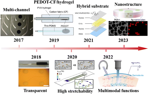 | ||
| Fig. 1 (a) Development of ECoG thin-film electrodes. Reprinted with permission from ref. 29. Copyright 2023, American Chemical Society. Reprinted with permission from ref. 30. Copyright 2022, Elsevier. Reprinted with permission from ref. 31. Copyright 2021, American Chemical Society. Reprinted with permission from ref. 32. Copyright 2020, Journal of Materiomics. Reprinted with permission from ref. 33. Copyright 2019, Scientific Reports. Reprinted with permission from ref. 34. Copyright 2018, Elsevier. Reprinted with permission from ref. 35. Copyright 2017, Elsevier. | ||
The configuration of semi-invasive electrodes requires good shape contact with the brain. However, traditional ECoG electrodes, due to the rigidity of silicon-based substrates and metal conductors, do not match the mechanical properties of the soft brain tissue, making them prone to damage.36 Polymer materials provide an excellent solution to avoid this mechanical mismatch. Conventional polymer materials, such as polydimethylsiloxane (PDMS),31,37–43 polyimide (PI)44 and parylene31,32,38,40,43,45–55 have a low Young's modulus. Some studies have achieved high tensile strength and good transparency using a combination of two polymer films. This opens up possibilities for further applications of ECoG electrodes in optogenetics, providing the potential for external control of the brain. PI can be used to form flexible films for circuit integration and active electronic devices through spin coating and electrospinning.56,57 Liquid crystal polymers (LCP) have also received more attention due to their excellent biocompatibility.58–60 Furthermore, to improve the conformal contact between the electrode and brain tissue, conductive polymers are typically coated on the surface of a metal layer. These polymer materials reduce the contact impedance between the electrode and the skin interface due to their good conductivity and flexibility compared to metal materials. Poly(3,4-ethylenedioxythiophene):poly(styrene sulfonate) (PEDOT:PSS) has high transparency and good conductivity, and these properties make this material widely used in the preparation of electrophysiological electrodes. Sergio et al. introduced PEDOT:PSS into Pt electrodes by electroplating, leading to a lower electrochemical impedance by approximately 30 times (from 971![[thin space (1/6-em)]](https://www.rsc.org/images/entities/char_2009.gif) 007 Ω to 30
007 Ω to 30![[thin space (1/6-em)]](https://www.rsc.org/images/entities/char_2009.gif) 407.6 Ω) at 1 kHz compared to the bare Pt electrode. Polymers can significantly improve the signal quality of ECoG, and they have become one of the most critical electrode components for brain biopotential recording.
407.6 Ω) at 1 kHz compared to the bare Pt electrode. Polymers can significantly improve the signal quality of ECoG, and they have become one of the most critical electrode components for brain biopotential recording.
With the growing interest in BCI, more and more articles are being published on understanding this interdisciplinary field.11 In terms of engineering, there is a focus on achieving more extensive and long-term recordings.61 These reports focused on the development, prospects, and application scenarios of BCIs.62 In terms of material science, conductive materials such as silicon-based materials,63 fiber materials,64 conjugated polymer materials,65 and semiconductor polymer materials66 have been reviewed and discussed. However, in most of these reviews, the electrodes were introduced only based on their physicochemical properties. There is still a lack of comprehensive discussion about the correlation between the structure, properties and signal performance.
In this work, the electrode performance was classified based on the detection requirements of ECoG signals, including electrical, mechanical, and optical properties. The criteria to be considered mainly include electrode-skin impedance, Young's modulus, and transparency, which are summarized. According to our investigation, the addition of polymer materials has brought improvements to ECoG thin-film electrodes in terms of conductivity and flexibility, demonstrating the potential for enhancing the electrode signal quality. In order to distinguish these polymer materials, they are divided into two categories based on their contribution to electrode properties. The first is sensitive materials, like PEDOT and PPy, which are in contact with the skin because of their high conductivity. The second type, structure materials, such as polydimethylsiloxane, parylene, polyimide, liquid crystal polymer etc., have been commonly used in the substrate and insulation layer of ECoG thin-film electrodes. The available electrode preparation methods and relevant properties are discussed. Finally, the challenges and perspectives of polymer-based ECoG thin-film electrodes are also discussed.
2. Characteristics of polymer materials
ECoG thin-film electrodes are divided into two parts: sensitive materials and structural materials. The sensitive materials provide the electrical properties required for the electrodes, while the structural materials like the substrate, insulation layer and sacrificial layer provide the mechanical and optical properties required for the electrodes, such as structural support, adhesion of metals, and improvement of transmittance.12The electrode materials and thin-film materials for ECoG thin-film electrodes are compared in Table 3. The performance of electrodes with different materials, including sensitive materials of Ti, Au, Cr, Pt, indium tin oxide (ITO), poly(3,4-ethylenedioxythiophene)-modified carbon fabric (PEDOT-CF), PEDOT:PSS, multiwalled carbon nanotubes (MWCNTs), and structure materials of polyvinyl alcohol (PVA), PDMS, PI, and polyethylene glycol terephthalate (PET) are listed.
| Sensitive materials | Structural materials | Property | Ref. | |
|---|---|---|---|---|
| 1 | Ti/Au | Parylene C and PDMS | Bending cycle reaches 200![[thin space (1/6-em)]](https://www.rsc.org/images/entities/char_2009.gif) 000 times impedance is 12.65 kΩ at 1 kHz charge storage capacity is 207.5 μC cm−2 000 times impedance is 12.65 kΩ at 1 kHz charge storage capacity is 207.5 μC cm−2 |
38 |
| 2 | Ti/Au | Parylene C | Impedance is 104 Ω level at 1 kHz long-term recording stability | 51 |
| 3 | Au | PI | Impedance is 107 Ω level at 1 kHz max strain less than 0.03% at 3.8 mm bending radius | 67 |
| 4 | Au | PI | Impedance is 1.1 ± 1.2 kΩ at 1 kHz | 68 |
| 5 | Au | Parylene and PDMS | Impedance between 50 and 70 kΩ at 1 kHz | 48 |
| 6 | Pt | OSTEMER 324 Flex | Surface curvature adapts to the brain | 69 |
| 7 | Cr/Au | BPDA-PD PI | Waterproofness | 70 |
| 8 | Cr/Au/Pt | Parylene C | Transparent | 47 |
| 9 | Pt | PI 2611 | Impedance is 102 Ω level at 1 kHz | 25 |
| 10 | Glassy carbon | PI | Impedance is 104 Ω level at 1 kHz (300 μm) | 71 |
| 11 | Glassy carbon | PI | Impedance is 104 Ω level at 1 kHz long-term recording stability | 72 |
| 12 | ITO | Parylene C and PDMS | Transparent | 52 |
| 13 | ITO | PI | Transparent | 34 |
| 14 | ITO | Parylene HT | Transparent | 50 |
| 15 | Carbon nanotube array | PDMS | Transparent extracellular ion monitoring | 41 |
| 16 | PEDOT-CF | PVA hydrogel and PDMS | Shape adaptability double layer capacitance is 70 mF cm−2 | 33 |
| 17 | PEDOT:Nafion coated gold | PI | |Z| values are about 100 kΩ at 1 kHz | 73 |
| 18 | PEDOT:PSS–ITO–Ag–ITO | Parylene C | Young's modulus is about 4.064 GPa the resistivity of the average thin layer resistance is 7.40 × 10⁻⁵ Ω cm transparent | 49 |
| 19 | (MWCNTs)/PEDOT:PSS | PDMS–parylene hybrid | Average impedance is 20.2 ± 7.9 kΩ at 1 kHz transparent | 31 |
| 20 | Silver and PEDOT:PSS | PET and parylene | Impedance is 81.4 ± 53.4 kΩ at 1 kHz transparent | 74 |
| 21 | Cr/Au/Ti coated PEDOT-CNT | PI | Impedance is 103 Ω level at 1 kHz | 75 |
| 22 | PEDOT:PSS coated Pt/Au/Pt | Parylene C and PDMS | Impedance is 30.4 ± 2.4 kΩ at 1 kHz transparent | 43 |
2.1 Electrical properties
Acquiring ECoG signals necessitates electrode materials possessing favorable electrical characteristics. For polymer materials, conductive polymers (CPs)76 with lower impedance are often used for electrodes. These CPs encompass organic polymeric conductors, such as PEDOT, polypyrrole (PPy), and polyaniline (PANI).77,78 PPy is a biocompatible substance extensively employed in biomedical scenarios, and it can be synthesized via chemical oxidation, electrochemical oxidation, and photopolymerization methods.79 PANI offers the advantages of cost-effectiveness and ease of synthesis. Nevertheless, the primary polymer chain's rigidity renders engaging in machining operations.80,81 PEDOT exhibits the advantages of good suppleness, high transparency, and good conductivity.82 Incorporating PSS into PEDOT yields water-soluble PEDOT:PSS, thereby enhancing its processing performance.83,84CPs can be modified onto the electrode surface via coating or electroplating methods, with the intention of mitigating electrode impedance. Sergio et al. employed electroplating to coat PEDOT:PSS onto the Pt electrode, reducing the electrochemical impedance by 30 fold.43Fig. 2a illustrates the contact impedance of PANI-coated electrodes and bare electrodes. The PANI coating leads to a reduction in electrode contact impedance (Z = 120 Ω cm2vs. Z = 1808 Ω cm2).85 Similarly, the same trend is observed with PPy coating. Rikky et al. compared the impedance of PPy + FOS (blue) with those of gold (red), unveiling a decrease in electrode impedance following PPy coating (Fig. 2b).8 Saeed et al. enhanced the conductivity from 10−4 to 10−2 by introducing oligoaniline into the composition.86 Yang et al. designed and added PEDOT:PSS on the surface of the ITO-Ag-ITO structure, which greatly reduced the electrode impedance.49 Moreover, the PEDOT:PSS coating further decreases the impedance. Castagnola et al. showed that the impedance of the gold-CNT-coated electrode impedance diminished by two-thirds compared to the bare sample, and the PEDOT-CNT-coated electrode achieved a two-order decrease in impedance at 100 Hz compared to the uncoated electrode.87 Moreover, the electrical performance of the electrode is related to its size; as the electrode diameter decreases, the background noise within the acquired signal exhibits a concurrent rise (Fig. 2c). However, small-sized ECoG electrodes are crucial for conducting experiments, and maintaining better electrical properties of ECoG electrodes at small sizes has become a challenge. Enhancing the electrical conductivity of materials offers a means to reduce the background noise.71 Following the application of PEDOT:PSS coating onto a glassy carbon (GC) electrode with a 50 μm thickness, a background noise intensity similar to a 300 μm diameter electrode can be achieved. This consequently mitigates the noise stemming from the reduction in electrode area.
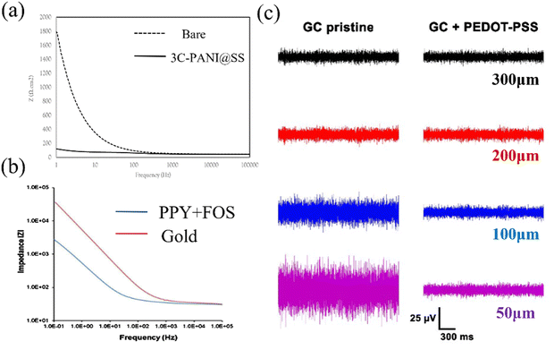 | ||
| Fig. 2 (a) The contact impedance between the PANI-coated electrode and bare electrode. Reprinted with permission from ref. 85. Copyright 2021, Elsevier. (b) Impedance diagram between the PPy coated electrode and bare electrode. Reprinted with permission from ref. 8. Copyright 2016, Elsevier. (c) The electrode noise effects of GC electrodes having different areas with PEDOT:PSS. Reprinted with permission from ref. 71. Copyright 2018, MDPI. | ||
2.2 Mechanical properties
The mechanical properties of the electrode are determined by its Young's modulus.88,89 Polymer materials are similar to brain tissues in terms of Young's modulus, distinguishing them from metal and non-metallic carbon-based materials (Fig. 3). The reported flexible substrate materials for electrodes include PI, PDMS, parylene, and LCP. These materials enable the electrode to achieve good flexibility and stretchability, resulting in improved comfort and good contact with the skin and underlying tissue. As a result of this increased flexibility, the electrode achieves improved accuracy and stability in acquiring ECoG signals.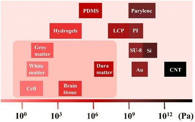 | ||
| Fig. 3 The Young's modulus of various materials, cells and brain tissues (scale bar). Data derived from ref. 1, 30, 42 and 58. | ||
Wu et al. mentioned that the modulus of the brain tissue is about 100 KPa, and that of the implantable Si electrode is about 150 GPa; this big mismatch will cause mechanical trauma, resulting in acute inflammation. They also measured the modulus of hydrogels: ∼100 kPa, Au: ∼80 GPa, and CNT: ∼1 TPa. Wang et al. reported that the modulus of white matter and grey matter is about 300 Pa and 450 Pa, and dura mater is about 1 MPa. Guo et al. calculated the Young's modulus of different soft film materials (PDMS: ∼1 MPa, PI: ∼2.8 GPa, parylene: ∼4.5 GPa, SU-8: ∼5.6 GPa). Yang et al. claimed that the modulus of LCP is from MPa to GPa levels. From the perspective of mechanical properties, hydrogel seems to be the most suitable material, but it is seriously affected by the moisture conditions and has high requirements for the use environment.
In many cases, PDMS and LCP emerge as more flexible options for a wide range of microfluidic applications and biomedical devices. Their flexibility and biocompatibility render them preferable choices. Conversely, in settings necessitating printed circuits or stringent conditions, PI stands out as an excellent option due to its high-temperature stability and chemical inertness, enabling optimal performance even under extreme circumstances. Moreover, parylene demonstrates proficiency in bonding with sensitive materials. Its highly uniform coating and good chemical inertness establish it as a frequently utilized protective coating in both biomedical and electronic devices.
2.3 Optical properties
In contrast to many metal and inorganic non-metallic counterparts, polymer materials typically exhibit superior light transmittance. This is beneficial for stimulating the brain with light to achieve disease treatment. The schematic diagram of light stimulation is shown in Fig. 4a. Fig. 4b shows an ECoG thin-film electrode made of various polymer materials, which has good transparency.30 For example, optogenetics affords targeted neuronal manipulation with millisecond precision,90 enabling the potential artificial regulation of brain nerve excitation through light stimulation for addressing neurodegenerative disorders, i.e., Parkinson's disease, epilepsy, and depression.91 Facilitated by highly light-transmissive ECoG electrodes, researchers employed optogenetics to modulate channel protein activity within the mouse brain, thus controlling nerve excitation and inhibition. Therefore, in recent years, there has been growing research on the application of transparent polymer materials in ECoG electrodes.92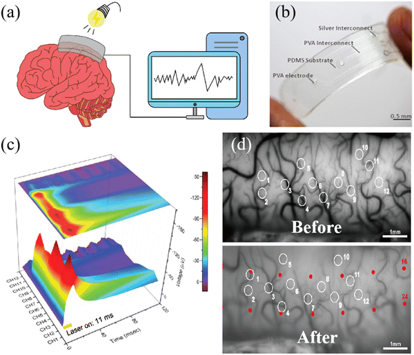 | ||
| Fig. 4 (a) The transparent ECoG thin-film electrode composed of multiple polymers. (b) Schematic of ECoG signal stimulated by light. Reprinted with permission from ref. 30. Copyright 2022, Elsevier. (c) The ECoG signal induced by continuous stimulation of the cerebral cortex of the marmoset by a blue laser pulse through a transparent electrode for 11 milliseconds. Reprinted with permission from ref. 93. Copyright 2019, WILEY. (d) Vascular images of cat visual cortex A18 before and after the installation of the ECoG thin-film electrode. Reprinted with permission from ref. 34. Copyright 2018, Elsevier. | ||
Concerning optical properties, glass is commonly used as an inorganic transparent material for comparison, and indium-doped tin oxide (ITO) constitutes a commonly used transparent thin-film material.94 Yang et al. compared the transmittance between ITO and PEDOT:PSS-ITO-Ag-ITO multilayer films on glass and parylene C substrates. They noted an increase in transmittance on parylene C substrates from 78% (ITO) to 85% (multilayered film). Similarly, on glass substrates, the transmittance rises from roughly 75% (ITO) to about 89% (multilayered film). The study validated that the parylene C multilayered film achieves transmittance at wavelengths of 470 nm, 550 nm, and 630 nm.46 Similarly, the electrode coated with PEDOT: PSS by Yang et al. showed stable signal-to-noise ratio (SNR) under different wavelengths of light conditions, with a variation of less than 2.7% and an average signal-to-noise ratio range of 35 db to 36 db. With the successful preparation of transmittance ECoG electrodes for more wavelengths of light, more choices can be obtained from light therapy to light stimulation.47 Similarly, changes in the intensity of ECoG signals can also be used to detect the health status of the brain. Fig. 4c displays the ECoG signals obtained by stimulating the marmoset brain with blue light. These signals were recorded using a 12-channel electrode. When the brain is affected by a virus, a high response is obtained through blue light stimulation, corresponding to the highest peak values of 150 μV in channels 1, 5, and 9 in Fig. 4c, which correspond to the virus-infected area. This method of detecting signals through transparent electrodes to obtain health status is very useful for medical diagnosis.49 Of course, it is important to note that the duration of light stimulation and irradiance levels will also impact the photogenetically evoked potential, as they directly influence the activation and response of photosensitive cells or molecules, thus affecting the magnitude and duration of the elicited neural activity.
3. Polymers for ECoG thin-film electrodes
In the following section, the materials are categorized as sensitive materials and structure materials. For each specific material, we will first introduce their preparation methods, followed by their properties.3.1. Sensitive materials
Conductive polymers (CPs) predominantly derive their structure from a sequence of alternating single and double bonds. This conjugated arrangement facilitates the facile movement of electrons within and between polymer chains, thereby elevating the conductivity of polymer materials.9 Notable instances include PANI,85,86 PPy95 and PEDOT.2,31,33,39,43,46,49,68,71,74,75,87,96–99 CPs typically exhibit flexibility, conductivity, biocompatibility, and facile processing at ambient temperatures. The techniques employed for depositing CPs onto electrodes primarily involve spin coating and electropolymerization.100 While spin coating technology is relatively straightforward, it is unsuitable for application on small, non-planar surfaces. In contrast, the electro-polymerization method proves to be a more precise approach for applying CPs to surfaces that are incompatible with spin coating techniques.97,101 For thin-film electrodes used in ECoG, the prevailing choice of CPs materials predominantly centers around PEDOT and PPy.75,96,97In terms of structure, the electrode employs electropolymerization to prepare a PEDOT layer at the base of the carbon fabric (CF) electrode in an effective way, as displayed in Fig. 5a.33 The reverse side of the electrode and the lead are insulated through a thin PDMS coating, while the outer layer is treated with a PVA hydrogel. This design ensures the electrode maintains conductivity while retaining flexibility equivalent to living tissues. Carbon nanotubes (CNTs) exhibit mechanical strength and electrical properties. The amalgamation of carbon nanotubes with PEDOT, leading to PEDOT-CNTs, enhances conductivity106–108 and stability and augments adhesion to the electrode surface. For instance, the nanocomposite electrode created by multiwalled carbon nanotubes (MWCNTs) in conjunction with PEDOT:PSS yields a rugged and porous surface via a network of interwoven nanostructures, as depicted in Fig. 5b.31 This configuration increases the electrochemical surface area and elevates electrode conductivity. Although high conductivity has been achieved, a stable testing in vivo environment is still lacking. The transparent electrode made by Donaldson et al. (as shown in Fig. 5c) was tested for impedance at 15 and 103 days of implantation to reflect the stability of the electrode, and the SNR of this electrode showed no significant difference before and after long-term storage. This electrode used transparent PEDOT:PSS as a replacement for silver interconnects within the transparency window, achieving electrodes with both good conductivity and transmissivity.74
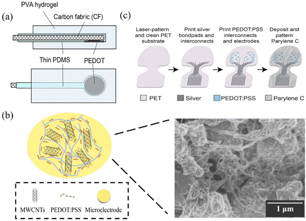 | ||
| Fig. 5 (a) Based on the cross-section (top) and bottom view of the hydrogel PEDOT-CF ECoG electrode, the PEDOT-CF electrode has low impedance and is good compared to other conductive polymers in chemical stability and electrical performance. Reprinted with permission from ref. 33. Copyright 2018, Scientific Reports. (b) Schematic representation of the electrochemical deposition of MWCNTs and PEDOT:PSS nanocomposites onto microelectrodes. The SEM image of the microelectrode structure is shown on the right. Reprinted with permission from ref. 31. Copyright 2021, American Chemical Society. (c) A structural schematic utilizing PET as a transparent patch material to enhance the transparency of the electrode window. This improvement is achieved through the implementation of PEDOT:PSS interconnects in the window area, enabling contact with inkjet-printed silver interconnects. Reprinted with permission from ref. 74. Copyright 2022, WILEY. | ||
In terms of functionality, PEDOT exhibits good conductivity, transmittance, and biocompatibility, and the schematic diagram of PEDOT deposition is shown in Fig. 6a. As depicted in Fig. 6b, it can be seen that when PEDOT-coated electrodes are implanted in the body (blue), there is a slight increase in impedance.31 However, in comparison to the bare gold electrode (black), the impedance of the PEDOT-coated electrode experiences a significant decrease. Elisa et al. discovered that applying the PEDOT-CNT coating results in an expansion of the effective area of the electrode nanostructure, leading to an augmentation in the charge exchange between the electrode and the solution. They find that the integral area on the cyclic voltammetry (CV) curve magnifies by a factor of 350, and the enhancement in charge transfer capability becomes more pronounced as the size of the electrode being coated increases.99 Additionally, the coating of PEDOT:PSS enhances electrical properties and also improves optical properties. Yang et al. revealed that due to the PEDOT:PSS coating, there is a slight increase in transmittance. This result makes the PEDOT:PSS polymer advantageous for preparing transparent electrodes.49
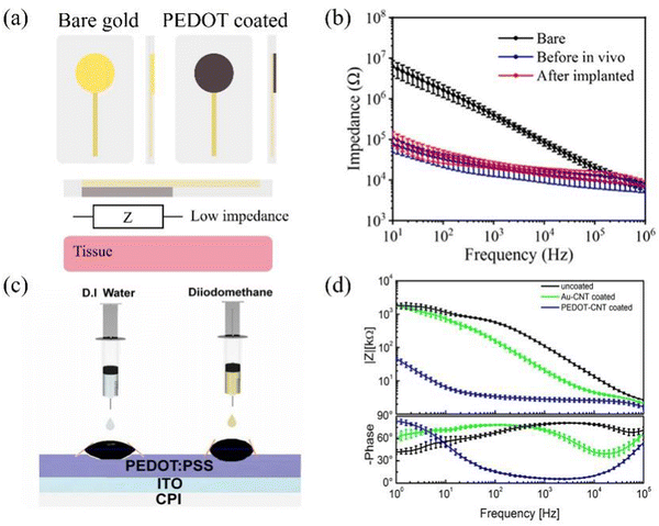 | ||
| Fig. 6 (a) Schematic of electrodes before and after coating PEDOT. (b) Impedance comparison diagram related to bare (black), before in vivo (blue) and after implanted (red). Reprinted with permission from ref. 31. Copyright 2021, American Chemical Society. (c) Measurement of the surface energy of the spin-coated PEDOT:PSS layer for the electrodes using D.I water and diiodomethane. Reprinted with permission from ref. 109. Copyright 2022, Elsevier. (d) Impedance spectra of uncoated (black), gold-CNT-coated (green), and PEDOT-CNT-coated (blue) electrodes (mean and standard deviation of 64 recording sites for each coating). Reprinted with permission from ref. 87. Copyright 2013, American Chemical Society. | ||
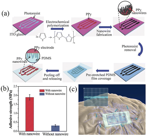 | ||
| Fig. 7 (a) A preparation method for PPy array electrodes. Reprinted with permission from ref. 95. Copyright 2017, WILEY. (b) Comparison of electrode adhesion before and after PPy nanowires modification. Reprinted with permission from ref. 95. Copyright 2017, WILEY. (c) Schematic diagram of the ECoG drug delivery device for treating epilepsy. Reprinted with permission from ref. 8. Copyright 2016, Elsevier. | ||
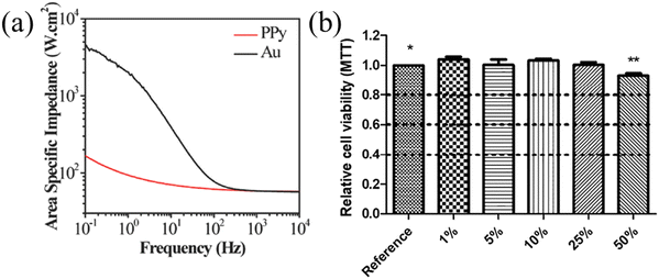
Fig. 8a shows the impedance test results of PPy thin-film and Au thin-film electrodes with the same geometric surface area. In comparison, the impedance of PPy films with the same surface area is smaller than 100 Hz. PPy not only has good conductivity but also biocompatibility and is widely used in the preparation of ECoG electrodes. Petr et al. proposed that iron(III) chloride is the oxidant of first choice in the preparation of PPy and displays biocompatibility. From long-term experience, they compared the two forms of PPy, salt and alkali, and found that both had lower cytotoxicity, while the alkaline form of PPy had lower cytotoxicity (Fig. 8b).79 Almira et al. pointed out in 2007 that PPy did not cause cytotoxicity in mouse peritoneal cells,111 making it an attractive material for biomedical applications in vivo.112 For example, PPy can be applied to delivery devices for epilepsy treatment drugs.8 Although PPy has its advantages, there is currently a problem of decreased conductivity due to peroxidation, which limits its long-term use.113
3.2 Structural materials
Ensuring good conformal properties of the electrode upon tissue contact has long been a pursuit in the development of flexible ECoG thin-film electrodes.114 The flexibility of the substrate directly impacts the overall flexibility of the electrode. Commonly employed flexible polymer materials for electrodes encompass PDMS, PI, parylene, and LCP. Over the recent years, the selection of patches for ECoG thin-film electrodes has expanded beyond individual polymer materials, with the emergence of composite structures that combine PDMS and parylene flexible films. This multilayer structure exhibits multiple advantageous properties that collectively enhance its ability to adapt to the intricate brain environment.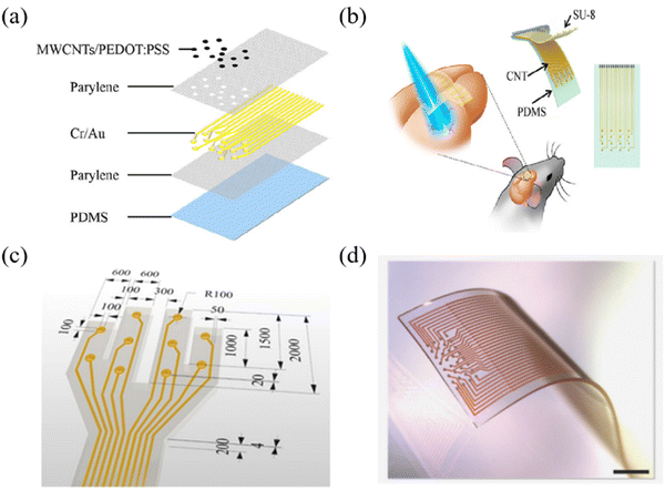 | ||
| Fig. 9 (a) A schematic of the electrode structure configuration using a two-layer parylene encapsulated metal electrode, PDMS as a flexible substrate and PEDOT:PSS as a contact coating. Reprinted with permission from ref. 31. Copyright 2021, American Chemical Society. (b) Schematics of the stretchable transparent CNT electrode array. Reprinted with permission from ref. 121. Copyright 2018, American Chemical Society. (c) Multichannel ECoG electrode for mixed PDMS-parylene C. Reprinted with permission from ref. 122. Copyright 2022, Elsevier. (d) Stretchable 32 channel electrode on the PDMS substrate (Scale bar, 1 mm). Reprinted with permission from ref. 122. Copyright 2022, Elsevier. | ||
The performance testing of PDMS focuses on mechanical properties, including finite element analysis,42 mechanical cycling testing and repeated extrusion testing. Zhao et al. fabricated a five-layer gold film structure electrode (green) with PDMS substrate and interlayer connection through Au nanopillars and compared its stretchability with single-layer gold film electrode (black) and double-layer gold film electrode (red) (Fig. 10a and b).37 The stretchability of the single-layer electrode is 80%, and that for the double-layer electrode is 120%, while the stretchability of the five-layer electrode reached 140%. Importantly, its resistance remained stable even after undergoing extensive cyclic testing. Chou et al. demonstrated the capability to execute a continuous bending cycle on the thin film, ranging from 0° to 180° and then returning to 0° at a rate of one cycle per second. Additionally, the bending cycles are performed on two distinct electrodes with varying traces, revealing no notable resistance alterations in either of the electrodes.38 The electrode remains mechanically intact after undergoing 200![[thin space (1/6-em)]](https://www.rsc.org/images/entities/char_2009.gif) 000 bending cycles. Li et al. used a compression-based technique to measure the average electrode phase change resulting from 100 and 1000 presses, which were −18.3 ± 4.9° and −19.1 ± 4.2°, and the impedance values were 20.5 ± 2.1 kΩ and 20.0 ± 1.6 kΩ at 1 Hz (Fig. 10c).31 Of course, mechanical stretching can also affect the optical properties of thin films. Zhang et al. found that at a 20% stretching degree, the transmittance of the CNT/PDMS electrode is higher than that at non-stretching (Fig. 10d).121
000 bending cycles. Li et al. used a compression-based technique to measure the average electrode phase change resulting from 100 and 1000 presses, which were −18.3 ± 4.9° and −19.1 ± 4.2°, and the impedance values were 20.5 ± 2.1 kΩ and 20.0 ± 1.6 kΩ at 1 Hz (Fig. 10c).31 Of course, mechanical stretching can also affect the optical properties of thin films. Zhang et al. found that at a 20% stretching degree, the transmittance of the CNT/PDMS electrode is higher than that at non-stretching (Fig. 10d).121
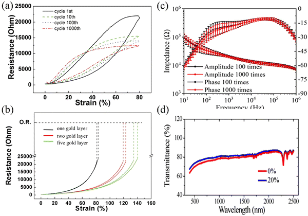 | ||
| Fig. 10 (a) The stretchability of the five-layer structure electrodes reaching 140% compared to 80% for the original one-layer electrodes and 120% for double-layered electrodes.37 (b) The resistance–strain curve of the five-layer electrodes after 1, 10, 100, and 1000 stretching cycles, indicating the stability of the electrode after prolonged stretching cycles.37 (c) Impedance of electrodes after pressing 100 and 1000 times. Reprinted with permission from ref. 31. Copyright 2021, American Chemical Society. (d) Optical transmittance of a CNT/PDMS complex before stretching and under stretching to a strain of 20%. Reprinted with permission from ref. 121. Copyright 2018, American Chemical Society. | ||
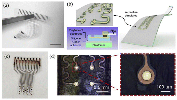 | ||
| Fig. 11 (a) The flexibility of an ECoG electrode prepared using parylene C as a substrate. Reprinted with permission from ref. 55. Copyright 2022, MDPI. (c) A parylene C coated electrode that has been stable for up to 56 days (equivalent to 115 days) in life testing. Reprinted with permission from ref. 51. Copyright 2022, Elsevier. (b and d) Schematic diagram and micrograph of a serpentine structure. (left 0.5 mm, right 100 μm) Reprinted with permission from ref. 32. Copyright 2019, Elsevier. | ||
In terms of mechanical properties, parylene exhibits a low Young's modulus. Yang et al. determined the Young's modulus of a parylene C film through cyclic nanoindentation testing, which remains relatively constant at approximately 4 GPa.49 As shown in Fig. 12a, Setogawa et al. calculated the bending stiffness of the device with and without the metal wiring layer as a function of the parylene thickness. Yamagiwa et al. presented the variation of deflection conducted on substrates composed of different thicknesses of parylene N and parylene C composites.54 As the temperature gradually increases, the deflection of the substrate material continues to increase, displaying the favorable application scenarios of parylene materials in the field of flexible electrode substrates. As shown in Fig. 12b, the resistance went up as the drop spacing increased. However, the growth rate of resistance on parylene is significantly lower than that on PDMS.126 Moreover, parylene exhibits good electrical and optical properties. Choi et al. developed a parylene-based ECoG electrode with an average impedance range of 3.7 kΩ to 1.6 mΩ (1 kHz: 13.9 kΩ) (Fig. 12c).127 In addition, the parylene electrode sputtered with ITO has a transmittance of 80% in the visible light region of 450–750 nm.52 Delamination is reported as one of the most common failure mechanisms of thin-film electrodes, and the adhesion force between the electrode and the film determines the lifespan of the electrode.128 Parylene materials have good adhesion performance in contrast to other polymer films, and peeling is commonly used to validate the adhesion strength of parylene to the electrode material. Nevertheless, this adhesion strength is susceptible to environmental factors. The peeling test was conducted following a 30-minute immersion in PBS, resulting in the detachment of some metals from the parylene film, indicating diminished adhesion of the parylene film to metals in humid conditions.38 Kim et al. compared the silver wire printed on PDMS (blue) and transferred it to a parylene film (red) as a function of drop spacing and conducted lifetime tests on parylene electrodes, revealing the alterations in electrode impedance and channel count, as depicted in Fig. 12d.51 Within 13 days, the initial impedance increased from 14.2 kΩ to 40 kΩ (n = 16), and after 13 days, the impedance of the electrode significantly decreased.
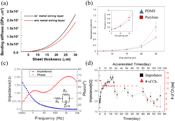 | ||
| Fig. 12 (a) Calculated bending stiffness of the device with and without the metal wiring layer as a function of the parylene thickness. Reprinted with permission from ref. 129. Copyright 2023, BMC. (b) Comparison of resistance between the two electrode preparation methods. Reprinted with permission from ref. 126. Copyright 2017, Elsevier. (c) Impedance and phase plots for the fabricated parylene C-based ECoG electrodes. Reprinted with permission from ref. 127. Copyright 2020, MDPI. (d) Plot shows the impedance variation and the number of alive channels during the lifetime test, reflecting the stability of the structure. Reprinted with permission from ref. 51. Copyright 2022, Elsevier. | ||
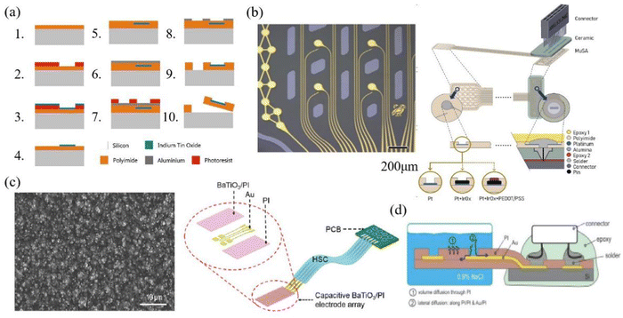 | ||
| Fig. 13 (a) Schematic of electrode preparation using PI as substrate. Reprinted with permission from ref. 34. Copyright 2018, Elsevier. (b) The manufacturing diagram is about a 32-channel conformal PI electrode that can better fit the surface of the brain and bring the electrode closer to the signal source. The left image depicts the microscopic view of the electrode area, measuring 200 μm. Reprinted with permission from ref. 23. Copyright 2017, Elsevier. (c) Electrode array created by integrating capacitive BaTiO3 and PI, with PI serving as an insulating protective layer. (The left image shows the SEM image of the prepared BaTiO3/PI composite film, measuring 10 μm) Reprinted with permission from ref. 67. Copyright 2017, WILEY. (d) The electrodes encapsulated with PI are immersed in salt water, reflecting the good waterproof properties of PI. Reprinted with permission from ref. 70. Copyright 2015, Elsevier. | ||
PI is being focused on in terms of mechanical properties, and Lin et al. investigated the alteration in conductor path resistance of the PI electrode under mechanical strain prior to fracture.131 The electrode resistance exhibited an almost linear increase with the rising applied mechanical strain, and the tensile performance reached a threshold of 10%, which is sufficient for implantation applications. Xu et al. measured the stress–strain curve and deformation force curve for PI films with thicknesses of 4 μm, 8 μm, 23 μm, and 50 μm. When the Young's modulus is similar, an increase in the thickness of the PI film leads to a corresponding rise in the ultimate tensile strength of the film.132 When the electrode is placed in the brain environment, the stability of the electrode in the humoral environment and the conformability of the test determine the signal quality of the electrode. Tolstosheeva et al. compared the impedance changes of long-cured PI, short-cured PI and parylene in 170 days of body fluid testing and found that long-term cured PI has good impedance stability and is suitable as a high waterproof barrier (Fig. 14a shows changes in impedance of long-cured PI). In Fig. 14b, a Comsol model was employed to test the stress distribution in a PI electrode with dimensions of 4 μm, 10 μm and 20 μm within the cerebral cortex of rats (with L0 representing the working area where the electrode contacts the cortex, and L1 indicating the opposite end of the electrode), the force required for 10 μm electrode to fit the brain is much smaller than that required for a 20 μm electrode. The miniaturization and lightweight development of the electrode can reduce the harm it brings to the subject.23 In terms of optical performance, Zátonyi et al. measured the optical transmission spectrum of PI/ITO/PI ECoG electrodes across wavelengths ranging from 400 nm to 720 nm. The transmittance throughout the entire wavelength range consistently remained at approximately 80% (Fig. 14c), and this reflects the good transmittance of PI.34
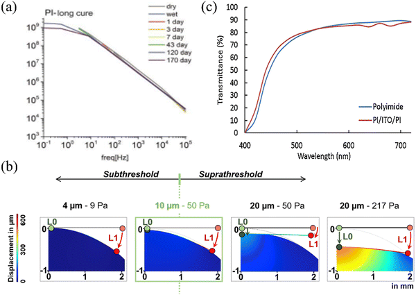 | ||
| Fig. 14 (a) Long term cured BPDA-PPD PI electrodes maintain stable impedance during long-term testing. Reprinted with permission from ref. 70. Copyright 2015, Elsevier. (b) Finite element analysis images of electrodes with varying thicknesses under diverse forces on the cerebral cortex surface. Reprinted with permission from ref. 23. Copyright 2020, Elsevier. (c) the transmittance of PI/ITO/PI ECoG electrodes. Reprinted with permission from ref. 34. Copyright 2018, Elsevier. | ||
Fig. 15a shows a design of the LCP electrode. Based on the improvement of electrode size, Chiang et al. designed five LCP thin-film electrodes based on thin-film technology, and these electrodes can be applied to collect ECoG signals from rodents, non-human primates and humans according to different application scenarios.133Fig. 15b shows the 25-channel neural electrodes with an LCP substrate. Woods et al. compared the electrode lifespans of LCP and PI, illustrating that the LCP-encapsulated gold electrode outperforms the PI-encapsulated gold electrode in terms of longevity.134 By predicting accelerated aging results, the device can maintain integrity for over 3.4 years. Using mechanical property testing, Chiang et al. compared and analyzed the maximum bending force that commercial and LCP thin-film electrodes may exert on the brain from the four-point bending test and brain geometry analysis.133 Nicholas et al. calculated the effective flexural modulus of LCP film, LCP thin-film ECoG array, silicon, the bending force of silicon-covered LCP, and commercial electrode. Then, they estimated the maximum force these components could exert on the human brain and found that the LCP thin film has a maximum pressure on the human brain that is only higher than the LCP film, and the Young's modulus is within 10−1 GPa.59 Michael et al. tested the biocompatibility of the LCP electrode. After 3 days and 28 days of recording, a comparison with the electrode experimental group revealed increased glial fibrillary acidic protein reactivity of astrocytes in the control group, whereas a minimal increase was observed in astrocyte activation in the electrode experimental group, indicating the favorable biocompatibility of the LCP electrode.135
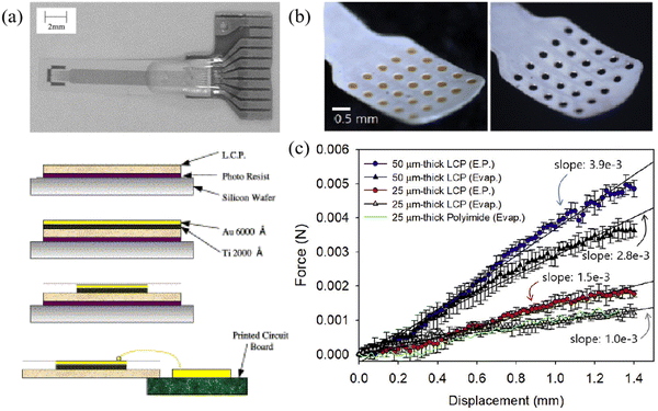 | ||
| Fig. 15 (a) The schematic and the fabrication process of the LCP electrode. Reprinted with permission from ref. 136. Copyright 2004, Elsevier. (b) 25 channel neural electrode electroplated gold (left) or iridium oxide (right) based on LCP. Reprinted with permission from ref. 137. Copyright 2019, Elsevier. (c) Bending force for LCP electrodes for electroplating (E.P.) and evaporation (Evap.), as well as flexibility comparison with PI electrodes. Reprinted with permission from ref. 137. Copyright 2019, Elsevier. | ||
4. Summary and outlook
The polymer materials have been extensively used for ECoG thin-film electrodes. Polymers such as PDMS provide flexibility to the structure of ECoG thin-film electrodes, while polymers such as PEDOT possess good conductivity to the ECoG thin-film electrodes. To enhance the electrical properties of polymers, the focus is now on minimizing impedance between brain tissue and electrodes. The application of conductive polymer coatings can further reduce the impedance compared to the uncoated electrodes. In terms of mechanical properties, flexible polymer materials have Young's modulus more similar to the brain tissue, providing greater comfort and less damage when placing the electrodes and making them easier to conform to the cerebral cortex. On this basis, the light transmittance of polymer materials can also provide a pathway for artificial regulation of brain activity through light stimulation. These aspects collectively underscore the merits of polymer-based ECoG thin-film electrodes.However, the focus of ECoG thin-film electrodes is on detecting high-quality signals and avoiding secondary damage. On the one hand, many polymer materials for electrodes are used to reduce damage to the brain tissue. On the other hand, subjecting individuals to craniotomies to remove the electrode after rescue or experiments can cause significant damage. If electrode materials could be engineered to undergo controlled degradation within tissue, the adverse effects of repetitive craniotomies could be averted. However, most currently available conductive polymers are not degradable. Natural polymers derived from organic sources present new perspectives; these materials exhibit good flexibility and biocompatibility and can even be safely dissolved or absorbed by the body.138,139 Chitosan, for instance, offers antimicrobial properties and modifiable conductivity; collagen provides a flexible and biocompatible matrix, while silk fibroin allows for tunable degradation rates. These polymers hold promise as potential materials for the next generation of ECoG thin-film electrodes. Furthermore, subjects often experience restricted mobility caused by the constraints of electrical wires connected to electrodes in long-term experiments with traditional ECoG electrodes.140,141 Wireless telemetry technology has brought about innovative solutions. By incorporating wireless telemetry modules onto thin films through strategic layering of various components, subjects can enjoy more freedom of movement during experiments. Despite numerous challenges, ECoG thin-film electrodes made of polymer materials continue to be widely utilized due to their exceptional properties.
Data availability
No primary research results, software or code has been included, and no new data were generated or analysed as part of this review.Conflicts of interest
The authors declare no conflict of interest.Acknowledgements
This review was supported by the National Natural Science Foundation of China (52203309, 52373240), the Shanghai Sailing Program (22YF1400400), the Shanghai Rising-Star Program (23QA1400100), the Fundamental Research Funds for the Central Universities (2232022D-09), and the Open Fund of State Key Laboratory of Biobased Fiber Manufacturing Technology (SKL202317), Key-Area Research and Development Program of Guangdong Province (2023B0303030002). L. Y. acknowledges the financial support from the Shenzhen Science and Technology Program (Grant No. RCBS20221008093340100) and the funding support of No. SE3Z007 and 52293425. S. S. acknowledges support from the RGC Postdoctoral Fellowship Scheme (P0052633).References
- N. Wu, S. Wan, S. Su, H. Huang, G. Dou and L. Sun, InfoMat, 2021, 3, 1174 CrossRef CAS.
- X. Wang, X. Sun, D. Gan, M. Soubrier, H.-Y. Chiang, L. Yan, Y. Li, J. Li, S. Yu, Y. Xia, K. Wang, Q. Qin, X. Jiang, L. Han, T. Pan, C. Xie and X. Lu, Matter, 2022, 5, 1204 CrossRef CAS.
- L. Wang, S. Liu, W. Zhao, J. Li, H. Zeng, S. Kang, X. Sheng, L. Wang, Y. Fan and L. Yin, Adv. Healthcare Mater., 2024, 2303316 CrossRef CAS PubMed n/a.
- A. Yu, M. Zhu, C. Chen, Y. Li, H. Cui, S. Liu and Q. Zhao, Adv. Healthcare Mater., 2024, 13, 2302460 CrossRef CAS PubMed.
- N.-I. Kim, J. Chen, W. Wang, J. Y. Kim, M.-K. Kwon, M. Moradnia, S. Pouladi and J.-H. Ryou, Adv. Healthcare Mater., 2024, 2303581 CrossRef CAS PubMed n/a.
- H. Liu, X. Yuan, T. Liu, W. Zhang, H. Dong and Z. Chu, Adv. Healthcare Mater., 2024, 2304355 CrossRef CAS PubMed n/a.
- X. Wang, X. Xiao, Z. Feng, Y. Wu, J. Yang and J. Chen, Adv. Healthcare Mater., 2023, 2303479 Search PubMed n/a.
- R. Muller, Z. Yue, S. Ahmadi, W. Ng, W. M. Grosse, M. J. Cook, G. G. Wallace and S. E. Moulton, Sens. Actuators, B, 2016, 236, 732 CrossRef CAS.
- R. Balint, N. J. Cassidy and S. H. Cartmell, Acta Biomater., 2014, 10, 2341 CrossRef CAS PubMed.
- I. Tubia, M. Mujika, J. Artieda, M. Valencia and S. Arana, Sens. Actuators, A, 2016, 251, 241 CrossRef CAS.
- G. Chen, D. Dang, C. Zhang, L. Qin, T. Yan, W. Wang and W. Liang, Soft Matter, 2024, 20, 7993 RSC.
- L. Sifringer, L. De Windt, S. Bernhard, G. Amos, B. Clément, J. Duru, M. W. Tibbitt and C. M. Tringides, J. Mater. Chem. B, 2024, 12, 10272 RSC.
- H. Dawit, Y. Zhao, J. Wang and R. Pei, Biomater. Sci., 2024, 12, 2786 RSC.
- M. E. E. Alahi, Y. Liu, Z. Xu, H. Wang, T. Wu and S. C. Mukhopadhyay, Mater. Today Commun., 2021, 29, 102853 CrossRef CAS.
- Q. Zeng and Z. Huang, Adv. Funct. Mater., 2023, 33, 2301223 CrossRef CAS.
- D. H. Szarowski, M. D. Andersen, S. Retterer, A. J. Spence, M. Isaacson, H. G. Craighead, J. N. Turner and W. Shain, Brain Res., 2003, 983, 23 CrossRef CAS PubMed.
- M. Jorfi, J. L. Skousen, C. Weder and J. R. Capadona, J. Neural Eng., 2015, 12, 011001 CrossRef PubMed.
- H. Wunderlich and K. L. Kozielski, Curr. Opin. Biotechnol, 2021, 72, 29 CrossRef CAS PubMed.
- J. Wang, T. He and C. Lee, Nano Energy, 2019, 65, 104039 CrossRef CAS.
- N. Sharafkhani, A. Z. Kouzani, S. D. Adams, J. M. Long, G. Lissorgues, L. Rousseau and J. O. Orwa, J. Neurosci. Methods, 2022, 365, 109388 CrossRef PubMed.
- G. Buzsáki, C. A. Anastassiou and C. Koch, Nat. Rev. Neurosci., 2012, 13, 407 CrossRef PubMed.
- Y. Shi, R. Liu, L. He, H. Feng, Y. Li and Z. Li, Smart Mater. Med., 2020, 1, 131 CrossRef.
- M. Vomero, M. F. Porto Cruz, E. Zucchini, F. Ciarpella, E. Delfino, S. Carli, C. Boehler, M. Asplund, D. Ricci, L. Fadiga and T. Stieglitz, Biomaterials, 2020, 255, 120178 CrossRef CAS PubMed.
- G. He, X. Dong and M. Qi, Mater. Res. Express, 2020, 7, 102001 CrossRef CAS.
- A. Zatonyi, F. Fedor, Z. Borhegyi and Z. Fekete, J. Neural Eng., 2018, 15, 054003 CrossRef CAS PubMed.
- M. McDonald, D. Sebinger, L. Brauns, L. Gonzalez-Cano, Y. Menuchin-Lasowski, M. Mierzejewski, O.-E. Psathaki, A. Stumpf, J. Wickham, T. Rauen, H. Schöler and P. D. Jones, Biosens. Bioelectron., 2023, 228, 115223 CrossRef CAS PubMed.
- X. Wei, L. Luan, Z. Zhao, X. Li, H. Zhu, O. Potnis and C. Xie, Adv. Sci., 2018, 5, 1700625 CrossRef PubMed.
- A. B. Rapeaux and T. G. Constandinou, Curr. Opin. Biotechnol, 2021, 72, 102 CrossRef CAS PubMed.
- C. Rinoldi, Y. Ziai, S. S. Zargarian, P. Nakielski, K. Zembrzycki, M. A. Haghighat Bayan, A. B. Zakrzewska, R. Fiorelli, M. Lanzi, A. Kostrzewska-Księżyk, R. Czajkowski, E. Kublik, L. Kaczmarek and F. Pierini, ACS Appl. Mater. Interfaces, 2023, 15, 6283 CrossRef CAS PubMed.
- X. Wang, M. Wang, H. Sheng, L. Zhu, J. Zhu, H. Zhang, Y. Liu, L. Zhan, X. Wang, J. Zhang, X. Wu, Z. Suo, W. Xi and H. Wang, Biomaterials, 2022, 281, 121352 CrossRef CAS PubMed.
- X. Li, Y. Song, G. Xiao, E. He, J. Xie, Y. Dai, Y. Xing, Y. Wang, Y. Wang, S. Xu, M. Wang, T. H. Tao and X. Cai, ACS Appl. Bio Mater., 2021, 4, 8013 CrossRef CAS PubMed.
- B. Ji, Z. Xie, W. Hong, C. Jiang, Z. Guo, L. Wang, X. Wang, B. Yang and J. Liu, J. Materiomics, 2020, 6, 330 CrossRef.
- S. Oribe, S. Yoshida, S. Kusama, S.-I. Osawa, A. Nakagawa, M. Iwasaki, T. Tominaga and M. Nishizawa, Sci. Rep., 2019, 9, 13379 CrossRef PubMed.
- A. Zátonyi, Z. Borhegyi, M. Srivastava, D. Cserpán, Z. Somogyvári, Z. Kisvárday and Z. Fekete, Sens. Actuators, B, 2018, 273, 519 CrossRef.
- S. Dong, W. Chen, X. Wang, S. Zhang, K. Xu and X. Zheng, Vacuum, 2017, 140, 96 CrossRef CAS.
- W. Chen, J. Lin, Z. Ye, X. Wang, J. Shen and B. Wang, Mater. Horiz., 2024 10.1039/D4MH00753K.
- Y. Zhao, C. Li, M. Yu and Z. Yu, APL Mater., 2019, 7, 101104 CrossRef.
- N. Chou, S. Yoo and S. Kim, IEEE Trans. Neural Syst. Rehabil. Eng., 2013, 21, 544 Search PubMed.
- A. Blau, A. Murr, S. Wolff, E. Sernagor, P. Medini, G. Iurilli, C. Ziegler and F. Benfenati, Biomaterials, 2011, 32, 1778 CrossRef CAS PubMed.
- M. Ochoa, P. Wei, A. J. Wolley, K. J. Otto and B. Ziaie, Biomed. Microdevices, 2013, 15, 437 CrossRef PubMed.
- H. Yang, Z. Qian, J. Wang, J. Feng, C. Tang, L. Wang, Y. Guo, Z. Liu, Y. Yang, K. Zhang, P. Chen, X. Sun and H. Peng, Adv. Funct. Mater., 2022, 32, 2204794 CrossRef CAS.
- L. Guo, G. S. Guvanasen, X. Liu, C. Tuthill, T. R. Nichols and S. P. DeWeerth, IEEE Trans. Biomed. Circuits Syst., 2013, 7, 1 Search PubMed.
- S. M. Vargo, T. Belloir, I. Kimukin, Z. Ahmed, D. J. Griggs, N. Stanis, A. Yazdan-Shahmorad and M. Chamanzar, Presented at 2023 11th International IEEE/EMBS Conference on Neural Engineering (NER), 24-27 April 2023, 2023 Search PubMed.
- U.-J. Jeong, J. Lee, N. Chou, K. Kim, H. Shin, U. Chae, H.-Y. Yu and I.-J. Cho, Lab Chip, 2021, 21, 2383 RSC.
- B. Ji, M. Wang, C. Ge, Z. Xie, Z. Guo, W. Hong, X. Gu, L. Wang, Z. Yi, C. Jiang, B. Yang, X. Wang, X. Li, C. Li and J. Liu, Biosens. Bioelectron., 2019, 135, 181 CrossRef CAS PubMed.
- W. Yang, Q. H. Fan and W. Li, Presented at 2020 IEEE 15th International Conference on Nano/Micro Engineered and Molecular System (NEMS), 27-30 Sept. 2020, 2020.
- T. J. Richner, S. Thongpang, S. K. Brodnick, A. A. Schendel, R. W. Falk, L. A. Krugner-Higby, R. Pashaie and J. C. Williams, J. Neural Eng., 2014, 11, 016010 CrossRef PubMed.
- W. R. Lee, C. Im, C. S. Koh, J. M. Kim, H. C. Shin and J. M. Seo, Presented at 2017 39th Annual International Conference of the IEEE Engineering in Medicine and Biology Society (EMBC), 11-15 July 2017, 2017 Search PubMed.
- W. Yang, Y. Gong, C.-Y. Yao, M. Shrestha, Y. Jia, Z. Qiu, Q. H. Fan, A. Weber and W. Li, Lab Chip, 2021, 21, 1096 RSC.
- A. Zatonyi, M. Madarasz, A. Szabo, T. Lorincz, R. Hodovan, B. Rozsa and Z. Fekete, J. Neural Eng., 2020, 17, 016062 CrossRef CAS PubMed.
- J.-H. Kim, D.-H. Baek, D. H. Kim and D.-W. Park, Curr. Appl. Phys., 2022, 39, 214 CrossRef.
- K. Y. Kwon, B. Sirowatka, A. Weber and W. Li, IEEE Trans. Biomed. Circuits Syst., 2013, 7, 593 Search PubMed.
- F. Vitale, W. Shen, N. Driscoll, J. C. Burrell, A. G. Richardson, O. Adewole, B. Murphy, A. Ananthakrishnan, H. Oh, T. Wang, T. H. Lucas, D. K. Cullen, M. G. Allen and B. Litt, PLoS One, 2018, 13, e0206137 CrossRef PubMed.
- S. Yamagiwa, M. Ishida and T. Kawano, Ieee, presented at 26th IEEE International Conference on Micro Electro Mechanical Systems (MEMS), Taipei, Taiwan, 2013 Jan 20-24, 2013 Search PubMed.
- Y. Kim, S. Alimperti, P. Choi and M. Noh, Sensors, 2022, 22, 1277 CrossRef CAS PubMed.
- S. Shi, Y. Si, Y. Han, T. Wu, M. I. Iqbal, B. Fei, R. K. Y. Li, J. Hu and J. Qu, Adv. Mater., 2022, 34, 2107938 CrossRef CAS PubMed.
- Y. Si, S. Shi and J. Hu, Nano Today, 2023, 48, 101723 CrossRef.
- Z. Yang, J. Zeng, Z. Yang, Y. Tong, Y. Lai and X. Cao, Polymer, 2022, 255, 125144 CrossRef CAS.
- N. S. Witham, C. F. Reiche, T. Odell, K. Barth, C.-H. Chiang, C. Wang, A. Dubey, K. Wingel, S. Devore, D. Friedman, B. Pesaran, J. Viventi and F. Solzbacher, J. Neural Eng., 2022, 19, 046041 CrossRef PubMed.
- R. Rihani, N. Tasnim, M. Javed, J. O. Usoro, T. M. D'Souza, T. H. Ware and J. J. Pancrazio, Neuromodulation, 2022, 25, 1259 CrossRef PubMed.
- L. Luan, J. T. Robinson, B. Aazhang, T. Chi, K. Yang, X. Li, H. Rathore, A. Singer, S. Yellapantula, Y. Fan, Z. Yu and C. Xie, Neuron, 2020, 108, 302 CrossRef CAS PubMed.
- H. Moon, J. Kwon, J. Eun, C. K. Chung, J. S. Kim, N. Chou and S. Kim, Adv. Mater. Technol., 2024, 9, 2301692 CrossRef.
- E. Song, J. Li, S. M. Won, W. Bai and J. A. Rogers, Nat. Mater., 2020, 19, 590 CrossRef CAS PubMed.
- C. Sung, W. Jeon, K. S. Nam, Y. Kim, H. Butt and S. Park, J. Mater. Chem. B, 2020, 8, 6624 RSC.
- Y. Liu, V. R. Feig and Z. Bao, Adv. Healthcare Mater., 2021, 10, 2001916 CrossRef CAS PubMed.
- I. B. Dimov, M. Moser, G. G. Malliaras and I. McCulloch, Chem. Rev., 2022, 122, 4356 CrossRef CAS PubMed.
- C. Chen, M. Xue, Y. Wen, G. Yao, Y. Cui, F. Liao, Z. Yan, L. Huang, S. A. Khan, M. Gao, T. Pan, H. Zhang, W. Jing, D. Guo, S. Zhang, H. Yao, X. Zhou, Q. Li, Y. Xia and Y. Lin, Adv. Healthcare Mater., 2017, 6, 1700305 CrossRef PubMed.
- A. Schander, S. Strokov, H. Stemmann, T. Teßmann, A. K. Kreiter and W. Lang, IEEE Sens. J., 2019, 19, 820 CAS.
- E. Borda, D. I. Medagoda, M. J. I. A. Leccardi, E. G. Zollinger and D. Ghezzi, Biomaterials, 2023, 293, 121979 CrossRef CAS PubMed.
- E. Tolstosheeva, V. Biefeld and W. Lang, Proc. Eng., 2015, 120, 36 CrossRef CAS.
- M. Vomero, E. Zucchini, E. Delfino, C. Gueli, N. C. Mondragon, S. Carli, L. Fadiga and T. Stieglitz, Materials, 2018, 11, 2486 CrossRef CAS PubMed.
- M. Vomero, E. Castagnola, J. S. Ordonez, S. Carli, E. Zucchini, E. Maggiolini, C. Gueli, N. Goshi, L. Fadiga, D. Ricci, S. Kassegne and T. Stieglitz, Presented at 2017 8th International IEEE/EMBS Conference on Neural Engineering (NER), 25-28 May 2017, 2017 Search PubMed.
- S. Carli, M. Bianchi, E. Zucchini, M. Di Lauro, M. Prato, M. Murgia, L. Fadiga and F. Biscarini, Adv. Healthcare Mater., 2019, 8, 1900765 CrossRef PubMed.
- P. D. Donaldson, Z. S. Navabi, R. E. Carter, S. M. L. Fausner, L. Ghanbari, T. J. Ebner, S. L. Swisher and S. B. Kodandaramaiah, Adv. Healthcare Mater., 2022, 11, 2200626 CrossRef CAS PubMed.
- E. Castagnola, L. Maiolo, E. Maggiolini, A. Minotti, M. Marrani, F. Maita, A. Pecora, G. N. Angotzi, A. Ansaldo, L. Fadiga, G. Fortunato and D. Ricci, Presented at 2013 6th International IEEE/EMBS Conference on Neural Engineering (NER), 6-8 Nov. 2013, 2013 Search PubMed.
- D. Kumar and R. C. Sharma, Eur. Polym. J., 1998, 34, 1053 CrossRef CAS.
- D. Olvera and M. G. Monaghan, Adv. Drug Delivery Rev., 2021, 170, 396 CrossRef CAS PubMed.
- I. Fratoddi, I. Venditti, C. Cametti and M. V. Russo, Sens. Actuators, B, 2015, 220, 534 CrossRef CAS.
- P. Humpolíček, V. Kašpárková, J. Pacherník, J. Stejskal, P. Bober, Z. Capáková, K. A. Radaszkiewicz, I. Junkar and M. Lehocký, Mater. Sci. Eng. C, 2018, 91, 303 CrossRef PubMed.
- S. Bhadra, D. Khastgir, N. K. Singha and J. H. Lee, Prog. Polym. Sci., 2009, 34, 783 CrossRef CAS.
- E. M. Geniès, A. Boyle, M. Lapkowski and C. Tsintavis, Synth. Met., 1990, 36, 139 CrossRef.
- M. A. Bhat, R. A. Rather and A. H. Shalla, Synth. Met., 2021, 273, 116709 CrossRef CAS.
- K. R. Ryan, M. P. Down, N. J. Hurst, E. M. Keefe and C. E. Banks, eScience, 2022, 2, 365 CrossRef.
- L. Ouyang, C. Musumeci, M. J. Jafari, T. Ederth and O. Inganäs, ACS Appl. Mater. Interfaces, 2015, 7, 19764 CrossRef CAS PubMed.
- H. Aghazadeh, M. K. Yazdi, A. Kolahi, M. Yekani, P. Zarrintaj, J. D. Ramsey, M. R. Ganjali, F. J. Stadler, M. R. Saeb and M. Mozafari, Curr. Appl. Phys., 2021, 27, 43 CrossRef.
- S. Manouchehri, B. Bagheri, S. H. Rad, M. N. Nezhad, Y. C. Kim, O. O. Park, M. Farokhi, M. Jouyandeh, M. R. Ganjali, M. K. Yazdi, P. Zarrintaj and M. R. Saeb, Prog. Org. Coat., 2019, 131, 389 CrossRef CAS.
- E. Castagnola, A. Ansaldo, E. Maggiolini, G. N. Angotzi, M. Skrap, D. Ricci and L. Fadiga, ACS Nano, 2013, 7, 3887 CrossRef CAS PubMed.
- G. A. Woods, N. J. Rommelfanger and G. Hong, Matter, 2020, 3, 1087 CrossRef PubMed.
- S.-H. Sunwoo, S. I. Han, H. Joo, G. D. Cha, D. Kim, S. H. Choi, T. Hyeon and D.-H. Kim, Matter, 2020, 3, 1923 CrossRef.
- E. S. Boyden, F. Zhang, E. Bamberg, G. Nagel and K. Deisseroth, Nat. Neurosci., 2005, 8, 1263 CrossRef CAS PubMed.
- Y. U. Cho, S. L. Lim, J.-H. Hong and K. J. Yu, npj Flexible Electron., 2022, 6, 53 CrossRef CAS.
- A. Yazdan-Shahmorad, C. Diaz-Botia, T. L. Hanson, V. Kharazia, P. Ledochowitsch, M. M. Maharbiz and P. N. Sabes, Neuron, 2016, 89, 927 CrossRef CAS PubMed.
- T. Araki, F. Yoshida, T. Uemura, Y. Noda, S. Yoshimoto, T. Kaiju, T. Suzuki, H. Hamanaka, K. Baba, H. Hayakawa, T. Yabumoto, H. Mochizuki, S. Kobayashi, M. Tanaka, M. Hirata and T. Sekitani, Adv. Healthcare Mater., 2019, 8, 1900130 CrossRef PubMed.
- B. Janarthanan, C. Thirunavukkarasu, S. Maruthamuthu, M. A. Manthrammel, M. Shkir, S. AlFaify, M. Selvakumar, V. R. M. Reddy and C. Park, J. Mol. Struct., 2021, 1241, 130606 CrossRef CAS.
- D. Qi, Z. Liu, Y. Liu, Y. Jiang, W. R. Leow, M. Pal, S. Pan, H. Yang, Y. Wang, X. Zhang, J. Yu, B. Li, Z. Yu, W. Wang and X. Chen, Adv. Mater., 2017, 29, 1702800 CrossRef PubMed.
- M. J. Donahue, A. Sanchez-Sanchez, S. Inal, J. Qu, R. M. Owens, D. Mecerreyes, G. G. Malliaras and D. C. Martin, Mater. Sci. Eng., R, 2020, 140, 100546 CrossRef.
- N. Rossetti, J. E. Hagler, P. Kateb and F. Cicoira, J. Mater. Chem. C, 2021, 9, 7243 RSC.
- S. Strokov, A. Schander, H. Stemmann, T. TeBmann, W. Lang and A. Kreiter, Presented at 2017 IEEE SENSORS, 29 Oct.-1 Nov. 2017, 2017 Search PubMed.
- E. Castagnola, L. Maiolo, E. Maggiolini, A. Minotti, M. Marrani, F. Maita, A. Pecora, G. N. Angotzi, A. Ansaldo, M. Boffini, L. Fadiga, G. Fortunato and D. Ricci, IEEE Trans. Neural Syst. Rehabil. Eng., 2015, 23, 342 Search PubMed.
- K. Gmucová, Curr. Opin. Electrochem., 2022, 36, 101117 CrossRef.
- Z. Song, Y. Ma, A. Morrin, C. Ding and X. Luo, TrAC, Trends Anal. Chem., 2021, 135, 116155 CrossRef CAS.
- P. Sakunpongpitiporn, K. Phasuksom, N. Paradee and A. Sirivat, RSC Adv., 2019, 9, 6363 RSC.
- Y. Hui, C. Bian, S. Xia, J. Tong and J. Wang, Anal. Chim. Acta, 2018, 1022, 1 CrossRef CAS PubMed.
- P. Yadav and A. Patra, Polym. Chem., 2020, 11, 7275 RSC.
- N. Matsuhisa, X. Chen, Z. Bao and T. Someya, Chem. Soc. Rev., 2019, 48, 2946 RSC.
- Y. Zhang, C. J. Sheehan, J. Zhai, G. Zou, H. Luo, J. Xiong, Y. T. Zhu and Q. X. Jia, Adv. Mater., 2010, 22, 3027 CrossRef CAS PubMed.
- N. Nandihalli, C.-J. Liu and T. Mori, Nano Energy, 2020, 78, 105186 CrossRef CAS.
- Y.-Z. Long, M.-M. Li, C. Gu, M. Wan, J.-L. Duvail, Z. Liu and Z. Fan, Prog. Polym. Sci., 2011, 36, 1415 CrossRef CAS.
- V. Raman, J.-E. Lee and H.-K. Kim, J. Alloys Compd., 2022, 903, 163799 CrossRef CAS.
- S. Machida, S. Miyata and A. Techagumpuch, Synth. Met., 1989, 31, 311 CrossRef CAS.
- A. Ramanaviciene, A. Kausaite, S. Tautkus and A. Ramanavicius, J. Pharm. Pharmacol., 2007, 59, 311 CrossRef CAS PubMed.
- Y. O. Mezhuev, M. I. Shtil’man and A. A. Artyukhov, Polym. Sci., Ser. D, 2021, 14, 427 CrossRef CAS.
- I. Gablech and E. D. Głowacki, Adv. Electron. Mater., 2023, 9, 2300258 CrossRef CAS.
- T. Cheng, Y. Zhang, W.-Y. Lai and W. Huang, Adv. Mater., 2015, 27, 3349 CrossRef CAS PubMed.
- M. Xu, D. Obodo and V. K. Yadavalli, Biosens. Bioelectron., 2019, 124–125, 96 CrossRef CAS PubMed.
- J. Liu, Y. Yao, X. Li and Z. Zhang, Chem. Eng. J., 2021, 408, 127262 CrossRef CAS.
- D. Qi, K. Zhang, G. Tian, B. Jiang and Y. Huang, Adv. Mater., 2021, 33, 2003155 CrossRef CAS PubMed.
- U. Eduok, O. Faye and J. Szpunar, Prog. Org. Coat., 2017, 111, 124 CrossRef CAS.
- M. P. Wolf, G. B. Salieb-Beugelaar and P. Hunziker, Prog. Polym. Sci., 2018, 83, 97 CrossRef CAS.
- Q.-C. Xia, M.-L. Liu, X.-L. Cao, Y. Wang, W. Xing and S.-P. Sun, J. Membr. Sci., 2018, 562, 85 CrossRef CAS.
- J. Zhang, X. Liu, W. Xu, W. Luo, M. Li, F. Chu, L. Xu, A. Cao, J. Guan, S. Tang and X. Duan, Nano Lett., 2018, 18, 2903 CrossRef CAS PubMed.
- S. Bhaskara, T. Sakorikar, S. Chatterjee, K. V. Shabari Girishan and H. J. Pandya, Sens. Bio-Sens. Res., 2022, 36, 100483 CrossRef.
- M. Golda-Cepa, K. Engvall, M. Hakkarainen and A. Kotarba, Prog. Org. Coat., 2020, 140, 105493 CrossRef CAS.
- T. Haggren, A. Shah, A. Autere, J.-P. Kakko, V. Dhaka, M. Kim, T. Huhtio, Z. Sun and H. Lipsanen, Nano Res., 2017, 10, 2657 CrossRef CAS.
- Y. X. Kato, I. Saito, H. Takano, K. Mabuchi and T. Hoshino, Neurosci. Lett., 2009, 464, 26 CrossRef CAS PubMed.
- Y. Kim, J. W. Kim, J. Kim and M. Noh, Sens. Actuators, B, 2017, 238, 862 CrossRef CAS.
- B.-J. Choi, J.-H. Kim, W.-J. Yang, D.-J. Han, J. Park and D.-W. Park, Appl. Sci., 2020, 10, 7364 CrossRef CAS.
- P. Oldroyd and G. G. Malliaras, Acta Biomater., 2022, 139, 65 CrossRef PubMed.
- S. Setogawa, R. Kanda, S. Tada, T. Hikima, Y. Saitoh, M. Ishikawa, S. Nakada, F. Seki, K. Hikishima, H. Matsumoto, K. Mizuseki, O. Fukayama, M. Osanai, H. Sekiguchi and N. Ohkawa, Mol. Brain, 2023, 16, 38 CrossRef PubMed.
- E. Tolstosheeva, V. Gordillo-González, T. Hertzberg, L. Kempen, I. Michels, A. Kreiter and W. Lang, Presented at 2011 Annual International Conference of the IEEE Engineering in Medicine and Biology Society, 30 Aug.-3 Sept. 2011, 2011 Search PubMed.
- J. H. Lin, Y. Wang, X. M. Wu, T. L. Ren and L. T. Liu, Presented at 2009 2nd International Conference on Biomedical Engineering and Informatics, 17-19 Oct. 2009, 2009 Search PubMed.
- F. Xu, Z. Zhou, H. Li and T. H. Tao, Presented at 2021 IEEE 34th International Conference on Micro Electro Mechanical Systems (MEMS), 25-29 Jan. 2021, 2021 Search PubMed.
- C.-H. Chiang, C. Wang, K. Barth, S. Rahimpour, M. Trumpis, S. Duraivel, I. Rachinskiy, A. Dubey, K. E. Wingel, M. Wong, N. S. Witham, T. Odell, V. Woods, B. Bent, W. Doyle, D. Friedman, E. Bihler, C. F. Reiche, D. G. Southwell, M. M. Haglund, A. H. Friedman, S. P. Lad, S. Devore, O. Devinsky, F. Solzbacher, B. Pesaran, G. Cogan and J. Viventi, J. Neural Eng., 2021, 18, 045009 CrossRef PubMed.
- V. Woods, M. Trumpis, B. Bent, K. Palopoli-Trojani, C.-H. Chiang, C. Wang, C. Yu, M. N. Insanally, R. C. Froemke and J. Viventi, J. Neural Eng., 2018, 15, 066024 CrossRef PubMed.
- M. Schweigmann, L. C. Caudal, G. Stopper, A. Scheller, K. P. Koch and F. Kirchhoff, Front. Cell. Neurosci., 2021, 15, 720675 CrossRef CAS PubMed.
- C. J. Lee, S. J. Oh, J. K. Song and S. J. Kim, Mater. Sci. Eng. C, 2004, 24, 265 CrossRef.
- J. Jeong, K. S. Min and S. J. Kim, Microelectron. Eng., 2019, 216, 111096 CrossRef CAS.
- B. Basavaraju, S. Nagaraja, A. R. Banagar, C. V. Srinivasa, B. T. Ramesh, D. Ramdan and M. I. Ammarullah, RSC Adv., 2024, 14, 33332 RSC.
- S. Dehghan-Chenar, H. R. Zare and Z. Mohammadpour, RSC Adv., 2024, 14, 33301 RSC.
- C. Meng, D. Snizhko, Y. T. Zholudov, W. Zhang, Y. Guan, Y. Tian and G. Xu, Chem. Commun., 2024, 60, 13546–13549 RSC.
- F. Chen, X. Song, J. Fu, J. Liang, J. Zhou, J. Cai, Y. Zhang, M. Zhu, Y. Ding, J. Jiang, Z. Chen, Y. Qi, Z. Zhou, Q. Huang, Y. Zhang and Z. Zheng, J. Mater. Chem. A, 2024, 12, 30298–30308 RSC.
| This journal is © The Royal Society of Chemistry 2025 |

