 Open Access Article
Solid bromine complexing agents: long-term solution for corrosive conditions in redox-flow battery†
Kobby
Saadi
a,
Raphael
Flack
a,
Valery
Bourbo
b,
Ran
Elazari
b and
David
Zitoun
 *a
*a
aDepartment of Chemistry and Bar-Ilan Institute of Nanotechnology and Advanced Materials, Bar-Ilan University, Ramat Gan 529002, Israel. E-mail: david.zitoun@biu.ac.il
bR&D, ICL Industrial products, Beer Sheva 8410101, Israel
First published on 12th December 2024
Abstract
Redox flow batteries (RFBs) fulfill the requirements for long-duration energy storage (LDES), and the use of bromine as a catholyte has garnered substantial interest due to its high availability and low cost. However, at high states of charge, the vapor pressure of bromine presents significant safety concerns within the catholyte tank, while polybromide species have been shown to corrode the metals present in the stack. Traditionally, soluble bromine complexing agents (BCAs) have been employed to mitigate the concentration of free bromine, providing some improvement in safety; however, this has often resulted in significant reductions in power density and durability. In this study, we present the development of a solid BCA incorporated into the catholyte tank of a hydrogen-bromine RFB (HBRFB). The long-term separation of the bromine-rich solid phase from the flowing liquid phases enables sustained high performance for over 250 cycles. The effective complexing-dissociating equilibrium within the electrolyte tank ensures adequate bromine concentration for operation at high current densities. This advancement significantly enhances the viability of bromine-based RFB technology as a dependable solution for long-duration energy storage.
1. Introduction
The raised interest in renewable energy sources in relation to the world climate crisis leads to accelerated development of useful and effective LDES. RFBs are considered as a high potential candidate which shows long term cycle life and effective energy-power decoupling.1–3 H2–Br2 RFBs use abundant and high energy density electrolytes.4–6 The liquid half-cell contains hydrobromic acid (HBr) in the discharged state which reacts to form bromine during charge as shown in the following eqn (1):7 | (1) |
The bromine tends to form well soluble polybromides as shown in eqn (2):8,9
| Br(aq)− + nBr2(l) ⇌ Br2n+1(aq)− n = 1, 2, 3 | (2) |
To reach and utilize the high energy density of this RFB (close to 200 W h L−1), a high concentration of bromine in the electrolyte is used, typically above [Br2] = 3 mol L−1, especially at high state of charge (SoC).10 The bromine vapor above the electrolyte solution raises safety issues. It also affects the longevity and durability of the RFB in addition to significantly increased cost for LDES.
The high polybromide crossover (mainly during gas flow break) through the membrane to the catalytic layer of the hydrogen electrode causes rapid corrosion of the hydrogen catalyst, which is usually from a precious group metal (PGM), and performance degradation; which increases the practical loading of PGM to one order of magnitude above the same electrode used in proton-exchanged membrane fuel cells (0.5 mgPGM cm−2 instead of 0.05 mgPGM cm−2).11–14
The corrosive electrolyte requires the use of highly resistant materials for all the equipment – tanks, pumps, pipelines, bipolar plates, sealing, sensors and flow meters; which dramatically increases the levelized cost of storage (LCOS).15,16 The corrosive electrolyte raises safety issues with additional detection and protection layers.17,18
Ammonium based molecules, a classical Lewis acid, have been proposed to complex the polybromide formed during the charge. This family of Lewis acids has been coined “bromine complexing agents or BCAs”. The BCA additive usually forms a denser liquid phase, named fused salt phase, with a very high bromine concentration (equivalent to 496.6 A h L−1 for 1-ethylpyridinium bromide). The ability to store a large volume of bromine in the fused salt phase at safer mode enables to significantly increase the capacity of the electrolyte and the total energy density of the system. Using a BCA in the RFB limits Br2 crossover and improves the coulombic efficiency of the Zn–Br RFB.19 Zn–Br and V–Br RFBs use N-methyl-ethyl-pyrrolidinium bromide (MEP) or N-methylethylmorpholinium bromide (MEM) and show the formation of a liquid fused salt phase from the Lewis acid–base complex formed.20,21 1-Ethylpyridinium bromide ([C2Py]Br) was tested in a HBRFB and showed a significant reduction of at least 90% of the bromine concentration in the aqueous electrolyte. However, the addition of BCA reduced the conductivity of the fused liquid dramatically (<98 mS cm−1) and lead to a high overvoltage.7,22
The interaction of the BCA cation (C2Py+) with the sulphonate groups in the perfluorosulfonic acid (PFSA) membrane in HBRFB irreversibly reduces the proton conductivity after a few cycles of operation. The polyvinylidene difluoride-silica (PVDF-SiO2) nanoporous membrane is more tolerant to the appearance of BCA in the system and its conductivity may recover after cycling.14,23 The high solubility of the proposed BCAs in the aqueous phase of the electrolyte prevents effective separation of the ionic salt from the active area of the MEA. This mixing harms RFB performance and limits the alternative solution of the high bromine concentration.
Recently, 1-n-hexylpyridin-1-ium bromide [C6Py]Br was investigated and showed that the increase in membrane resistance is reversible after exposure to C6Py+ cation, in contrast to C2Py+ cations, mainly due to its longer side chain. A high electrolyte capacity of 176.7 A h L−1 was attained for at least 12 cycles.24 This low number of cycles was achieved at a current density of 100 mA cm−2 which reveals the poor kinetics of liquid-phase BCA in HBRFB (in addition to the membrane fouling).
Herein, solid-phase BCA (SBCA) is investigated as an additive to the catholyte in HBRFB. The ability of this solid to rapidly complex and decomplex the polybromide species improves the safety of the system, while the absence of membrane fouling stabilizes its long-term performance. The cell was cycled at the high current density of 300 mA cm−2, similar to the cell without BCA and 3 times above the liquid-phase BCA. The SBCA cell was cycled for 250 cycles without any sign of degradation (20 times more than with liquid BCA). Furthermore, this finding enables the reduction of PGM loading, the utilization of more concentrated electrolytes with higher storage capacity and the reduction of LCOS by employing common equipment.
2. Experimental
2.1. Electrolyte
SBCA (ICL-IP) was provided as 0.3 mm beads and used as received. 1-Ethylpyridinium bromide ([C2Py]Br or MEP, liquid BCA), HBr 48% and bromine (ICL-IP) were used as received. In order to understand the effect of the SBCA on the conductivity of the electrolyte, it was measured at different SoCs and temperatures, along with the bromine concentration in the aqueous phase at each level.2.2. Membrane-electrode assembly
The membrane which was used in the cells was based on PVDF and SiO2 as the nanometric ceramic powder.25 The pretreatment process to extract the pore-former from the dry membrane was described in our previous paper.14 The thickness of the PVDF–SiO2 membrane was 200 μm.The electrode support is based on SGL 29AA carbon paper. All layers were applied using a doctor's blade coater.
2.3. RFB operation
The MEA was located between two graphite plates and two copper plates which were used as current collectors. The cells were operated with constant flow of dry hydrogen and 20 mL of recycled 6.6 M HBr solution (12 mL min−1) at 60 °C. The gas pressure (1 atm gauge) was controlled by a needle valve on the exhaust line of the cell. Polarization curves, electrochemical impedance spectroscopy (EIS) and cycling tests were collected on a Biologic Science Instruments BCS-815 battery cycler. The electrochemical impedance spectroscopy (EIS) was measured with 10 mV amplitude around the OCV and frequency range from 1 Hz to 8 kHz.After OCV stabilization the HBr electrolyte (6.6 M – 0% SoC) was deeply charged to SoC of 90% (0.66 M HBr and 2.94 M Br2) and polarization and EIS tests were performed. SBCA small spherical beads were gradually added to the electrolyte tank under effective stirring and up to the point that the vapor above the solution disappeared (Fig. 1). After OCV stabilization, the cell was tested again for polarization and EIS. For long term durability, cycling at constant current was performed under two different limitations:
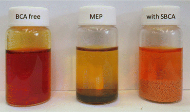 | ||
| Fig. 1 HBr 6.6 M electrolyte (SoC 66%) without (right) and with liquid (center) and solid (right) BCA. | ||
(a) Voltage limited (0.7–1.1 V)
(b) Constant charge (charge – 1 A h; discharge – 0.9 A h).
3. Results and discussion
3.1. SBCA effect on the electrolyte
The solid porous resin of SBCA features a diameter ranging from 0.3 to 1 mm. This resin exhibits chemical resistance to bromine and hydrobromic acid and is synthesized from a polymer that incorporates surface-quaternary ammonium (R4N+) bromide groups. The combination of these quaternary ammonium bromides and the resin's porous architecture facilitates the hosting and complexation of bromine within the bead, as described by the following equilibrium:| Br2 + R4N+Br− ⇌ R4N+Br3− |
| SoC [%] | HBr [M] | Br2 [M] without SBCA | Br2 [M] with SBCA |
|---|---|---|---|
| 0 | 6.6 | 0.0 | 0.0 |
| 17 | 5.4 | 0.6 | 0.11 |
| 33 | 4.4 | 1.1 | 0.36 |
| 66 | 2.2 | 2.2 | 0.72 |
| 90 | 0.6 | 3.0 | 0.62 |
Addition of the SBCA to the charged electrolyte significantly reduced the bromine concentration in the aqueous phase of the electrolyte, and the bromine vapor above the liquid disappeared (Fig. 1). At a high SoC of 90% only one third of the bromine remains dissolved and available for quick reaction (from 3 to 0.96 M at 50 °C, Table 1 and Fig. 2A) while its majority is safely complexed by the agent. As shown at Fig. 2A, a lower concentration of HBr at high SoC slightly reduces the electrolyte density.
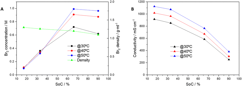 | ||
| Fig. 2 Dependence on SoC at 30, 40 and 50 °C with SBCA for (A) Br2 concentration and electrolyte density and (B) electrolyte ionic conductivity. | ||
Above the level of ∼60% SoC the electrolyte reaches its maximal bromine capacity relative to the HBr level, and excess bromine above this level is complexed in the SBCA beads. Fig. 2B shows constant conductivity reduction upon SoC. Despite the decreased concentration of HBr, which is responsible for the electrolyte conductivity, the conductivity is still sufficient up to a high SoC of 80% for high cell performance.
3.2. SBCA effect on the polarization curve and EIS
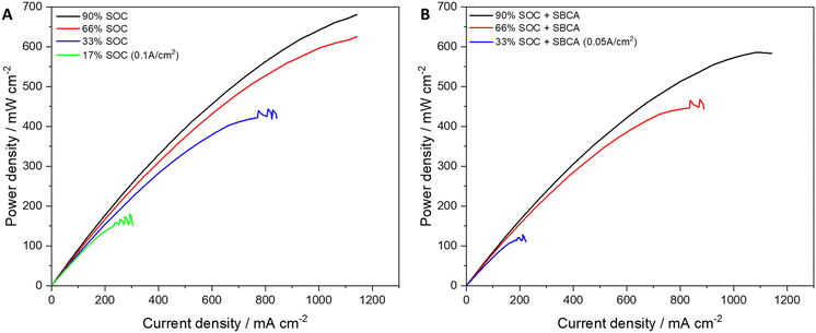
RFB cells were assembled and charged to SoC of 90% before polarization and EIS testing. It was gradually discharged to lower SoC (66/33/17%) and at each level the polarization and EIS were measured. The minimal possible SoC of 17% was obtained after reducing the current density to 0.1 A cm−2. After electrolyte replacement and initial charging to SoC of 90%, 2.4 g of SBCA were added to the electrolyte tank. Polarization and EIS were measured and the electrolyte was gradually discharged to lower SoC (66/33/31%) and at each level polarization and EIS were measured. To obtain the low SoC (below 40%) the current density was reduced to 0.05 A cm−2. The polarization curves at different SoC with and without SBCA are compared in Fig. 3.The reduction in maximal power density is inversely proportional to the SoC. While at a high SoC the difference is only 14%, at 33% SoC the SBCA in the electrolyte reduces the cell performance by 71%. The SBCA free cell at 17% SoC reached a higher peak power than the cell with the SBCA at almost double SoC. The meaning of this result is that the irreversible charge of the cell is doubled when the SBCA is involved. The reduction in the availability of bromides for reaction is reflected also in the EIS measurements (Table 2). A lower concentration of the flowing electrolyte causes an increase in the resistance for charge transfer (RCT).
| SoC [%] | SBCA free | With SBCA | ||
|---|---|---|---|---|
| R S | R CT | R S | R CT | |
| 90 | 31.3 | 4.8 | 30.2 | 4.5 |
| 66 | 28.4 | 4.2 | 29.8 | 5.3 |
| 33 | 28.7 | 5.5 | 30.2 | 7 |
| 31 | — | — | 30.1 | 8 |
| 17 | 30.4 | 4.5 | — | — |
3.3. RFB cycling
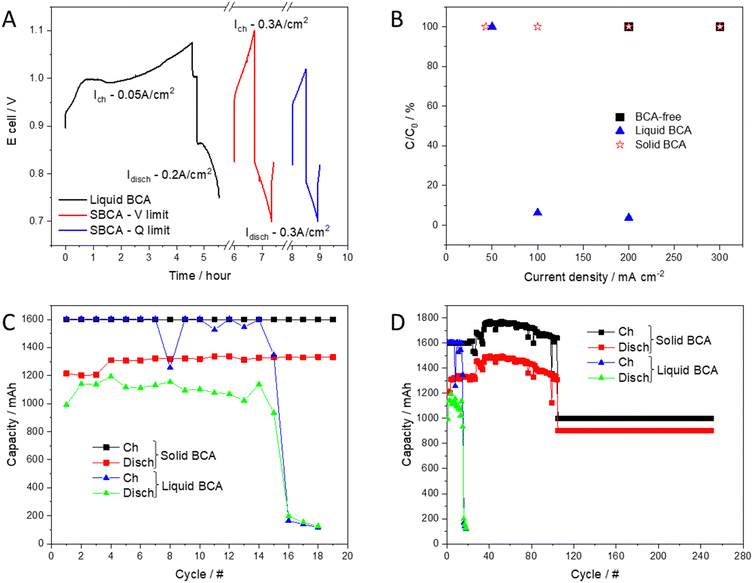
To investigate the integration of the solid bromine complexing agent (SBCA) in a real system and understand its effect on performance, durability and safety, the RFB was cycled in two modes (voltage limited and capacity limited) at 0.3 A cm−2, and compared to the liquid (MEP, and BCA-free cells). Fig. 4A compares the voltage profile of each complexation phase and emphasizes the advantages of the solid BCA. Comparing the relative capacity (C/C0) at evaluated current densities which applied with each BCA (Fig. 4B) shows the limited performance of the liquid BCA cell.The SBCA cell shows very high stability in both modes of operation. In the first 100 cycles, the SBCA cell was cycled in galvanostatic mode with a voltage range limitation (0.7–1.1 V). After 100 cycles, capacity limited mode was applied (capacity limits: charge – 1 A h; discharge – 0.9 A h). Fig. 4C and D compare the long term cycling of the SBCA cell to the cell with liquid BCA, which was investigated and published before.14Fig. 4C zooms in the first 20 cycles of the long-term comparison, which are shown in Fig. 4D.
While addition of liquid BCA to catholyte critically harms the RFB performance, SBCA contributes to the cycling stability and improves system's safety. The liquid BCA dissolves in the acidic environment and spreads with the assistance of the flowing electrolyte all over the cell, reduces the membrane and electrodes activity and causes its collapsing after less than 20 cycles. In contrast, the ability of the SBCA to keep the complexation reaction away from the membrane, the electrodes and the active area of the MEA, enables its stable and long-term cycling. Down the line, the effectiveness of the solid BCA compared to soluble BCA can be measured by the levelized cost of storage (LCOS). According to our simple calculations on the lifetime of the cells, given that the energy density of the system is almost constant with or without BCA whatever its state, the better durability of the system with a solid BCA could decrease the LCOS by one order of magnitude compared to a system with soluble BCA. This crude calculation should also consider the ability to opt for more affordable materials owing to the less corrosive electrolytes: less precious group metals, less fluoride-based tubing, metallic bipolar plates and simple tanks.
Polarization along 250 cycles shows impressive stability (Fig. 5). The low bromine concentration in the aqueous phase, as presented before, decreases the exposure of each component in the cell to the corrosive element and enables its operation in moderate conditions. Lower bromine crossover through the membrane decelerates its aging (Fig. S2 and Table S1, ESI†). The first RCT was higher than the 250th. In the first cycle, the membrane was affected from the high concentration of bromine in the initial deep charging to 90% SoC before SBCA addition. Upon cycling, the bromine concentration in the membrane reduces and consequently RCT decreases.
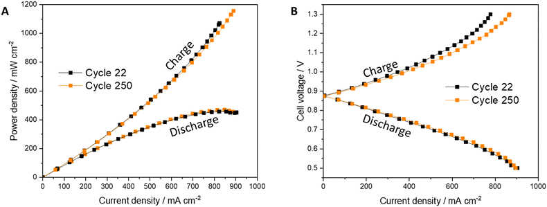 | ||
| Fig. 5 Polarization measurements results of (A) power density and (B) cell's voltage of the RFB with SBCA at the beginning of life (Cycle 22) and after 250 cycles. | ||
The cell tested with liquid BCA (named MEP or [C2Py]Br) shows poor cycling, mainly during at the beginning of the charge when the voltage rises rapidly (Fig. 6A). After only 16 cycles, this overvoltage prevented the cell from cycling, as it reached the upper limit (Fig. 6B and C). The liquid BCA caused a significant reduction in cell performance which forced cycling (mainly charging) at low current density. The cell tested with SBCA shows a stable voltage profile even after 250 cycles, as shown at Fig. 6D.
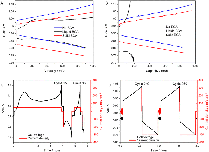 | ||
| Fig. 6 Voltage profile of cell without BCA, with liquid (MEP) or solid BCA: (A) 1st cycle; (B) 16th cycle. Galvanostatic cycling: (C) 16th cycle with MEP; (D) 250th cycle with SBCA. | ||
The energy efficiency of cycling was reduced to a safer mode. The SBCA free cell shows coulombic efficiency (CE) of 95% and energy efficiency (EE) of 75%, which decrease with SBCA to 90% (CE) and 66% (EE). This is in accord with the lower electrolyte concentration window.
The exposure of the catalytic metal to bromide species during cell operation is critical to its durability. Irreversible adsorption of bromides to the catalytic metal in the hydrogen electrode reduces its electrocatalytic surface area (ECSA) and harms the electrode's performance. A similar polarization after 250 cycles indicates that the electrocatalytic layer is available for the hydrogen reactions as new, even at high current density (up to 0.9 A cm−2). Using an exact amount of SBCA enables effective performance of the RFB even at a high current density without suffering the harmful consequences of high bromine species in the flowing electrolyte.
To examine the long-term stability of the SBCA in the corrosive environment of the catholyte, SBCA beads were socked in electrolyte at different states of charge (SOC) for 1 year. Table S2 (ESI†) shows very low carbon residue (total organic content: TOC) in the electrolyte, which indicates minimal SBCA degradation over a year. Note that the initial socking shows no degradation (non-measurable TOC) in the different electrolytes.
4. Conclusions
In this study, we present the novel integration of a solid bromine complexing agent (SBCA) into a hydrogen-bromine redox flow battery (RFB) for the first time, to the best of our knowledge. The inclusion of SBCA significantly mitigates the corrosiveness of the system, thereby enhancing its long-term stability and safety. During cycling at a current density of 0.3 A cm−2, the RFB incorporating SBCA in the catholyte tank exhibited a consistent polarization curve over 250 cycles. Notably, a small quantity of SBCA spherical beads complexes 66% of the bromine in the charged electrolyte, effectively preventing all degradation processes associated with this energy storage system. The reduced bromine concentration in the aqueous phase diminishes the detrimental crossover of bromide species to the catalyst layer of the hydrogen electrode. Furthermore, the SBCA inhibits the corrosion of platinum group metals (PGM) and preserves the high electrochemical surface area (ECSA) of the electrode, which is dedicated solely to hydrogen reactions. Concurrently, within the electrolyte tank, the equilibrium between complexed bromine and dissolved bromine in the aqueous phase is both rapid and reversible, sustaining high performance levels and safety. The resultant reduction in overall corrosiveness in bromine-based RFB systems is anticipated to yield substantial cost savings through decreased PGM loading. This advancement allows for the utilization of simpler system components and enhances the longevity of the stationary energy storage system.Author contributions
Kobby Saadi: investigation, data curation, visualization, writing – original draft. Raphael Flack: investigation, writing – original draft. Valery Bourbo: data curation, visualization. Ran Elazari: validation, supervision, review & editing supervision. David Zitoun: investigation, data curation, supervision, funding acquisition, writing – original draft, review & editing, revision & suggestions.Data availability
All the data presented in an article is available in the manuscript.Conflicts of interest
There are no conflicts to declare.Acknowledgements
We would like to thank the R&D division of ICL Industrial Product, Beer Sheva, Israel for supporting this work. This study was partially supported by the Israel ministry of energy and the Israel Innovation Authority. K. S. was partially supported by a Shulamit Aloni grant from the ministry of science and technology. R. F. express his gratitude to the ministry of absorption for a fellowship.References
- G. L. Soloveichik, Flow Batteries: Current Status and Trends, Chem. Rev., 2015, 115(20), 11533–11558, DOI:10.1021/cr500720t.
- M. Park, J. Ryu, W. Wang and J. Cho, Material design and engineering of next-generation flow-battery technologies, Nat. Rev. Mater., 2016, 2(1), 1–18, DOI:10.1038/natrevmats.2016.80.
- Y. V. Tolmachev, Review—Flow Batteries From 1879 To 2022 And Beyond, J. Electrochem. Soc., 2023, 170, 030505, DOI:10.1149/1945-7111/acb8de.
- R. S. Yeo and D. T. Chin, A Hydrogen-Bromine cell for Energy Storage applications, J. Electrochem. Soc., 1979, 127(3), 549–555 CrossRef.
- J. A. Kosek and A. B. Laconti, Advanced hydrogen electrode for a hydrogen-bromine battery, J. Power Sources, 1988, 22(3–4), 293–300, DOI:10.1016/0378-7753(88)80024-7.
- G. G. Barna, S. N. Frank, T. H. Teherani and L. D. Weedon, Lifetime Studies In H2/Br2Fuel Cells, J. Electrochem. Soc., 1984, 131(9), 1973–1980, DOI:10.1149/1.2116003.
- M. Küttinger, R. Riasse, J. Wlodarczyk, P. Fischer and J. Tübke, Improvement of safe bromine electrolytes and their cell performance in H2/Br2 flow batteries caused by tuning the bromine complexation equilibrium, J. Power Sources, 2022, 520, 230804, DOI:10.1016/j.jpowsour.2021.230804.
- R. W. Ramette and D. A. Palmer, Thermodynamics of tri- and pentabromide anions in aqueous solution, J. Solution Chem., 1986, 15(5), 387–395, DOI:10.1007/BF00646261.
- P. K. Adanuvor, R. E. White and S. E. Lorimer, The Effect of the Tribromide Complex Reaction on the Oxidation/Reduction Current of the Br2/Br-Electrode, J. Electrochem. Soc., 1987, 134(6), 1450–1454, DOI:10.1149/1.2100688.
- M. Küttinger, J. K. Wlodarczyk, D. Daubner, P. Fischer and J. Tübke, High energy density electrolytes for H2/Br2redox flow batteries, their polybromide composition and influence on battery cycling limits, RSC Adv., 2021, 11(9), 5218–5229, 10.1039/d0ra10721b.
- G. Gershinsky, P. Nanikashvili, R. Elazari and D. Zitoun, From the Sea to Hydrobromic Acid: Polydopamine Layer as Corrosion Protective Layer on Platinum Electrocatalyst, ACS Appl. Energy Mater., 2018, 1(9), 4678–4685, DOI:10.1021/acsaem.8b00808.
- G. Lin, P. Y. Chong and V. Yarlagadda, et al., Advanced Hydrogen-Bromine Flow Batteries with Improved Efficiency, Durability and Cost, J. Electrochem. Soc., 2016, 163(1), A5049–A5056, DOI:10.1149/2.0071601jes.
- K. T. Cho, M. C. Tucker and A. Z. Weber, A Review of Hydrogen/Halogen Flow Cells, Energy Technol., 2016, 4(6), 655–678, DOI:10.1002/ente.201500449.
- K. Saadi, M. Kuettinger, P. Fischer and D. Zitoun, Hydrogen-Bromine Redox-Flow Battery Cycling with Bromine Complexing Agent: on the Benefits of Nanoporous Separator Versus Proton Exchange Membrane, Energy Technol., 2021, 9(2), 1–10, DOI:10.1002/ente.202000978.
- N. Singh and E. W. McFarland, Levelized cost of energy and sensitivity analysis for the hydrogen-bromine flow battery, J. Power Sources, 2015, 288, 187–198, DOI:10.1016/j.jpowsour.2015.04.114.
- Y. A. Hugo, W. Kout, G. Dalessi, A. Forner-Cuenca, Z. Borneman and K. Nijmeijer, Techno-economic analysis of a kilo-watt scale hydrogen-bromine flow battery system for sustainable energy storage, Processes, 2020, 8(11), 1–22, DOI:10.3390/pr8111492.
- M. Küttinger, P. A. Loichet Torres, E. Meyer, P. Fischer and J. Tübke, Systematic study of quaternary ammonium cations for bromine sequestering application in high energy density electrolytes for hydrogen bromine redox flow batteries, Molecules, 2021, 26(9), 2721, DOI:10.3390/molecules26092721.
- A. Trovò, G. Marini, W. Zamboni and S. D. Sessa, Redox Flow Batteries: A Glance at Safety and Regulation Issues, Electronics, 2023, 12(8), 1844, DOI:10.3390/electronics12081844.
- M. Küttinger, P. A. Loichet Torres, E. Meyer and P. Fischer, Properties of Bromine Fused Salts Based on Quaternary Ammonium Molecules and Their Relevance for Use in a Hydrogen Bromine Redox Flow Battery, Chem. – Eur. J., 2022, 28(13), e202103491, DOI:10.1002/chem.202103491.
- D. C. Constable, K. J. Cathro, K. Cedzynska and P. Melbourne, Some properties of zinc/bromine battery, J. Power Sources, 1985, 16, 53–63 CrossRef.
- W. Kautek, A. Conradi and M. Sahre, et al., In Situ Investigations of Bromine-Storing Complex Formation in a Zinc-Flow Battery at Gold Electrodes, J. Electrochem. Soc., 1999, 146(9), 3211–3216, DOI:10.1149/1.1392456.
- M. Küttinger, R. Brunetaud, J. K. Włodarczyk, P. Fischer and J. Tübke, Cycle behaviour of hydrogen bromine redox flow battery cells with bromine complexing agents, J. Power Sources, 2021, 495, 229820, DOI:10.1016/j.jpowsour.2021.229820.
- Y. A. Hugo, N. Mazur, W. Kout, F. Sikkema, Z. Borneman and K. Nijmeijer, Effect of Bromine Complexing Agents on Membrane Performance in Hydrogen Bromine Flow Batteries, J. Electrochem. Soc., 2019, 166(13), A3004–A3010, DOI:10.1149/2.0951913jes.
- M. Küttinger, K. Saadi, T. Faverge, N. R. Samala, I. Grinberg, D. Zitoun and P. Fischer, Influence of strong bromine binding complexing agent in electrolytes on the performance of hydrogen/bromine redox flow batteries, J. Energy Storage, 2023, 70, 107890, DOI:10.1016/j.est.2023.107890.
- E. Peled, T. Duvdevani and A. Melman, A Novel Proton-Conducting Membrane, Electrochem. Solid-State Lett., 1998, i(5), 210–211 CrossRef.
- K. Saadi, P. Nanikashvili and Z. Tatus-Portnoy, et al., Crossover-tolerant coated platinum catalysts in hydrogen/bromine redox flow battery, J. Power Sources, 2019, 422, 84–91, DOI:10.1016/j.jpowsour.2019.03.043.
Footnote |
| † Electronic supplementary information (ESI) available. See DOI: https://doi.org/10.1039/d4ya00367e |
| This journal is © The Royal Society of Chemistry 2025 |

