 Open Access Article
Creative Commons Attribution 3.0 Unported Licence
Effects of annealing conditions on the battery anode properties of multilayer graphene due to layer exchange
R.
Ito
a,
K.
Nozawa
a,
N.
Saitoh
b,
N.
Yoshizawa
c,
T.
Suemasu
a and
K.
Toko
 *a
*a
aInstitute of Applied Physics, University of Tsukuba, 1-1-1 Tennodai, Tsukuba, Ibaraki 305-8573, Japan
bElectron Microscope Facility, AIST, 1-1-1 Higashi, Tsukuba, Ibaraki 305-8564, Japan
cGlobal Zero Emission Research Center, AIST, 16-1 Onogawa, Tsukuba, Ibaraki 305-8569, Japan
First published on 28th December 2024
Abstract
The annealing conditions of the layer-exchange synthesis of multilayer graphene significantly affected its crystallinity and lithium-ion battery anode properties. We demonstrated excellent capacity retention and fast charge–discharge properties in multilayer graphene synthesized at low temperatures (400 °C). These results could contribute to the realization of flexible thin-film batteries.
Thin-film batteries with solid electrolytes have attracted considerable attention as a next-generation energy solution owing to their superior energy efficiency, cost-effectiveness, safety, and installation flexibility.1,2 Graphite, which is commonly used as an anode material in conventional liquid lithium-ion batteries (LIBs), exhibits stable properties even when paired with other carrier ions3,4 or solid electrolytes.5 The synthesis of graphite as a thin film on various substrates could provide a reliable anode for advanced thin-film batteries. However, the synthesis of bulk graphite on any substrate is challenging as the synthesis temperature is usually above 1000 °C. Graphene, a two-dimensional sheet of graphite, has been synthesized at low temperatures using metal-catalyzed vapor-phase growth6–10 or solid-phase growth.11–13 As an anode material, graphene has an extremely high specific capacity because of its high specific surface area.14–16 A stable operation over graphite has also been observed with multilayer graphene (MLG).17–21 However, the use of a thin MLG anode is impractical because of its limited capacity per area. Obtaining thick MLG (i.e., graphite thin film) through conventional low-temperature synthesis methods which involve heating the solid solution and cooling to precipitate carbon on metal catalysts remains challenging.
Layer exchange (LE) is a technique for forming polycrystalline semiconductor thin films on various substrates by exchanging layers of metal and amorphous semiconductors during a heat treatment process.22–25 We discovered that eight different metals can induce LE with amorphous carbon (a-C), leading to the formation of MLG.26–28 The resulting MLG exhibited properties comparable to those of bulk graphite when used as an anode electrode for LIBs.29–31 The shape of the MLG conformed to that of the initial metal layer, allowing precise control of thickness control over a wide range.32,33 In this study, we investigated the effect of LE synthesis temperature on the anode properties of MLG. Lower synthesis temperatures resulted in better anode properties, and paved the way for the development of flexible thin-film batteries using plastic substrates.
Fig. 1(a) illustrates the schematic of the LE process. We formed MLG using a Ni-induced LE with an inverted structure, which self-assembles into a Ni bottom electrode.24,29 We sequentially deposited Ni and a-C thin films, each with a thickness of 200 nm, on Mo foils. All depositions were performed using radio-frequency (RF) magnetron sputtering (Sanyu Electron SVC-700RF, base pressure: 3.0 × 10⁻⁴ Pa) with Ar plasma. The RF power was set to 50 and 100 W for Ni and a-C, respectively. The samples were subjected to heat treatment at growth temperatures (Tg) of 800 °C for 10 min, 600 °C for 8 h, and 400 °C for 15 h. For Tg = 600 °C and 800 °C, the samples were removed from the sputtering equipment and annealed in a furnace (Koyo Thermo Systems KTF035N1) with an Ar atmosphere. For Tg = 400 °C, the sample was annealed inside the sputtering equipment without exposure to the atmosphere, a method that prevents oxygen contamination of the a-C films and enables crystallization at low temperatures.24,34 We note that 400 °C was approximately the lower limit of annealing temperature at which layer exchange of carbon occurred, while carbon on the Mo substrate sublimated during annealing at 900 °C. Therefore, Tg ranged from 400 to 800 °C. The samples, as depicted in Fig. 1(b), were analyzed using Raman spectroscopy (JASCO NRS-5100; spot diameter, 5 μm; wavelength, 532 nm), scanning electron microscopy (SEM, Hitachi High-Technologies SU-8020), and transmission electron microscopy (TEM, FEI Tecnai Osiris) at 200 kV, equipped with energy dispersive X-ray (EDX). As shown in Fig. 1(c), coin-type cells were fabricated using the MLG electrode, pure Li metal foil, and a separator (Celgard 2400) immersed in an electrolyte. The electrolyte used was lithium hexafluorophosphate (LiPF6) (1 mol L−1) in ethylene carbonate (EC)/diethyl carbonate (DEC) (1![[thin space (1/6-em)]](https://www.rsc.org/images/entities/char_2009.gif) :
:![[thin space (1/6-em)]](https://www.rsc.org/images/entities/char_2009.gif) 1 volume ratio). The characteristics of the anode were examined using an electrochemical measuring instrument (Meiden Hokuto HJ1001SD8).
1 volume ratio). The characteristics of the anode were examined using an electrochemical measuring instrument (Meiden Hokuto HJ1001SD8).
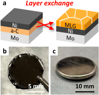 | ||
| Fig. 1 Sample outline of this study. (a) Schematic of the LE process. Photographs of the (b) sample after LE and (c) coin cell battery. | ||
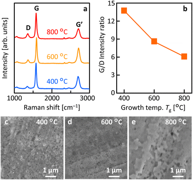
Fig. 2(a) shows that the Raman spectra of all samples have peaks at approximately 1350, 1580, and 2700 cm−1, which correspond to the D, G, and G′ peaks in the graphitic structure, respectively.35 These results indicate that LE occurred in all Tg samples and that MLG was synthesized. Fig. 2(b) demonstrates that the G/D ratio, which corresponds to the crystallinity of MLG, is higher at lower Tg. For the sample synthesized at Tg = 400 °C, the G/D ratio reached 13.7, which is higher than that of most low-temperature-synthesized MLGs.36–40 This trend in the G/D ratio is reasonable, considering that, in general, grain size expansion and orientation increase with lower temperatures in the LE process.23 Annealing in vacuum, avoiding atmospheric exposure, may also have been effective in improving MLG crystallinity. Fig. 2(c)–(e) show that the surface morphology of MLG varies with Tg. All samples exhibited common directional linear patterns originating from the polishing marks on the Mo foil. At Tg = 400 °C, voids were observed in the MLG, suggesting partially incomplete LE. At Tg = 600 °C, the MLG formed relatively uniformly. At Tg = 800 °C, the MLG was relatively rough, which could be attributed to Ni agglomeration during high-temperature annealing.
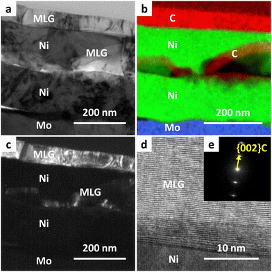
We investigated the detailed cross-sectional structure of the sample synthesized at Tg = 400 °C. Fig. 3(a) shows that the film formed on Mo exhibits a complex stacking structure, which differs from the structure typically obtained by standard inverted LE.23,24Fig. 3(b) indicates that MLG was formed on the top surface, with the Ni layer positioned at the bottom through the LE, while MLG was also present within the Ni layer. A similar structure has been reported in the LE of the Si–Al system, which was attributed to nucleation occurring within the metal layer.41,42Fig. 3(c)–(e) illustrates that the MLG layers are oriented parallel to the Ni interface, a common characteristic of MLGs with high interfacial energy anisotropy. Notably, the lattice image in Fig. 3(d) suggests that the MLG is highly crystalline despite its low synthesis temperature.
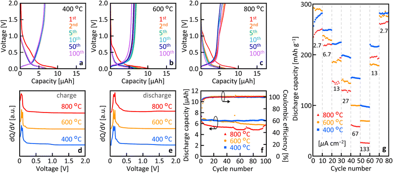
Fig. 4(a)–(c) show that, for all Tg, the samples exhibited clear charge/discharge operation over 100 cycles. The initial charge capacity was elevated owing to the formation of a solid electrolyte interface (SEI) at 0.73 V, which resulted in a faradaic reduction of the electrolyte.43 The quality of SEI would be roughly equivalent to bulk graphite, while there may be some heterogeneity due to the defects in the current MLG. Fig. 4(d) and (e) show a distinct peak around 0.06 V in the dQ/dV curve, which is a typical potential corresponding to the deinsertion of lithium ions into graphite.21,44Fig. 4(f) illustrates the cycle characteristics derived from the charge–discharge characteristics. For all samples, the coulombic efficiency was relatively low in the first cycle owing to irreversible capacity formation but maintained a high value of nearly 100% during subsequent cycles. As the number of cycles increased, the discharge capacity gradually decreased for Tg = 600 °C and 800 °C, whereas it remained almost constant for Tg = 400 °C. The discharge capacity at Tg = 400 °C was 6.53 μAh after 100 cycles, which corresponds to about 98% of the initial cycle discharge capacity. Fig. 4(g) shows the current rate characteristics of the discharge capacity. Similar to general anodes, the capacitance decreases with increasing current rate, which is dependent on Tg. The capacitance tended to be higher at lower Tg values, particularly at higher current rates.
We observed the state of the MLG layers after disassembling coin cells that had undergone 100 charge/discharge cycles. Fig. 5 shows that the surface morphology depends on Tg. For the Tg = 400 °C sample, the MLG layer shows a uniform surface texture (Fig. 5(a)), which is the same as that before charge/discharge operation. In contrast, the Tg = 600 °C and 800 °C samples show cracks and partial delamination of the MLG layer, respectively (Fig. 5(b) and (c)). These behaviors indicate that the MLG layer was damaged during the charge/discharge process, likely due to the volume change caused by the deinsertion of lithium ions. These results agree with the Tg dependent charge/discharge characteristics. Based on the Raman results, it appears that the high crystallinity of the MLG synthesized at low temperatures may be responsible for its excellent film strength.
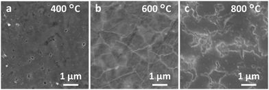 | ||
| Fig. 5 Surface SEM images of the samples after 100 cycles of charge/discharge at the current density of 13 μA cm−2, where Tg = (a) 400 °C, (b) 600 °C, and (c) 800 °C. | ||
Conclusions
The effect of annealing conditions of MLG anodes on the LIB properties of MLG anodes was studied. The LE method allowed MLG to be synthesized within the temperature range of 400–800 °C. Raman measurements, electron microscopy, and charge–discharge analyses indicated that Tg affected the crystallinity and anode properties of MLG; a lower Tg resulted in higher crystallinity and improved charge–discharge properties. Notably, the MLG synthesized at 400 °C exhibited excellent cycle stability and current rate performance, highlighting its potential for practical applications in flexible thin-film batteries. This study demonstrates that low-temperature synthesis of MLG is crucial for developing next-generation energy solutions.Data availability
Data for this article are available at Open Science Framework at https://osf.io/tgrjs.Conflicts of interest
There are no conflicts to declare.Acknowledgements
This work was financially supported by the JSPS KAKENHI (22K18802) and the JST FOREST Program (JPMJFR222J). The experiments were conducted at the International Center for Young Scientists at NIMS and the Nanotechnology Platform at the University of Tsukuba.Notes and references
- H. Nishide and K. Oyaizu, Science, 2008, 319, 737–738 CrossRef CAS PubMed.
- Y. Pang, J. Pan, J. Yang, S. Zheng and C. Wang, Electrochem. Energy Rev., 2021, 4, 169–193 CrossRef CAS.
- M. Shen, H. Ding, L. Fan, A. M. Rao, J. Zhou and B. Lu, Adv. Funct. Mater., 2023, 33, 2213362 CrossRef CAS.
- P. Luo, Y. Liu, W. Luo, H. Fu, J. Chen, H. Ding, C. Gao and B. Lu, J. Mater. Chem. A, 2024, 12, 16410–16418 RSC.
- K. Takada, Acta Mater., 2013, 61, 759–770 CrossRef CAS.
- M. H. Rümmeli, A. Bachmatiuk, A. Scott, F. Börrnert, J. H. Warner, V. Hoffman, J.-H. Lin, G. Cuniberti and B. Büchner, ACS Nano, 2010, 4, 4206–4210 CrossRef PubMed.
- J.-I. Fujita, T. Hiyama, A. Hirukawa, T. Kondo, J. Nakamura, S. Ito, R. Araki, Y. Ito, M. Takeguchi and W. W. Pai, Sci. Rep., 2017, 7, 12371 CrossRef PubMed.
- H. J. Park, B. W. Ahn, T. Y. Kim, J. W. Lee, Y. H. Jung, Y. S. Choi, Y. I. Song and S. J. Suh, Thin Solid Films, 2015, 587, 8 CrossRef CAS.
- K. Murakami, S. Tanaka, A. Hirukawa, T. Hiyama, T. Kuwajima, E. Kano, M. Takeguchi and J. Fujita, Appl. Phys. Lett., 2015, 106, 093112 CrossRef.
- Y. Nakajima, H. Murata, N. Saitoh, N. Yoshizawa, T. Suemasu and K. Toko, ACS Omega, 2019, 4, 6677–6680 CrossRef CAS PubMed.
- K. Koshida, K. Gumi, Y. Ohno, K. Maehashi, K. Inoue and K. Matsumoto, Appl. Phys. Express, 2013, 6, 105101 CrossRef.
- J. Kwak, J. H. Chu, J.-K. Choi, S.-D. Park, H. Go, S. Y. Kim, K. Park, S.-D. Kim, Y.-W. Kim, E. Yoon, S. Kodambaka and S.-Y. Kwon, Nat. Commun., 2012, 3, 645 CrossRef PubMed.
- Y. Chen, J. Wang, P. Schützendübe, Z. Wang and E. J. Mittemeijer, Carbon, 2020, 159, 37–44 CrossRef CAS.
- N. Li, Z. Chen, W. Ren, F. Li and H.-M. Cheng, Proc. Natl. Acad. Sci. U. S. A., 2012, 109, 17360–17365 CrossRef CAS PubMed.
- D. Wei, S. Haque, P. Andrew, J. Kivioja, T. Ryhänen, A. Pesquera, A. Centeno, B. Alonso, A. Chuvilin and A. Zurutuza, J. Mater. Chem. A, 2013, 1, 3177 RSC.
- N. J. Dudney, Mater. Sci. Eng. B, 2005, 116, 245–249 CrossRef.
- G. Radhakrishnan, J. D. Cardema, P. M. Adams, H. I. Kim and B. Foran, J. Electrochem. Soc., 2012, 159, A752 CrossRef CAS.
- H. Sun, A. Varzi, V. Pellegrini, D. A. Dinh, R. Raccichini, A. E. Del Rio-Castillo, M. Prato, M. Colombo, R. Cingolani, B. Scrosati, S. Passerini and F. Bonaccorso, Solid State Commun., 2017, 251, 88–93 CrossRef CAS.
- R. Mo, D. Rooney, K. Sun and H. Y. Yang, Nat. Commun., 2017, 8, 13949 CrossRef CAS PubMed.
- T. M. Paronyan, A. K. Thapa, A. Sherehiy, J. B. Jasinski and J. S. D. Jangam, Sci. Rep., 2017, 7, 39944 CrossRef CAS PubMed.
- H. Song, R. Na, C. Hong, G. Zhang, X. Li, Y. Kang, Q. Zhang and H. Xie, Carbon, 2022, 188, 146–154 CrossRef CAS.
- Z. Wang, L. Gu, F. Phillipp, J. Y. Wang, L. P. H. Jeurgens and E. J. Mittemeijer, Adv. Mater., 2011, 23, 854 CrossRef CAS PubMed.
- K. Toko and T. Suemasu, J. Phys. D: Appl. Phys., 2020, 53, 373002 CrossRef CAS.
- K. Toko and H. Murata, Nanotechnology, 2021, 32, 472005 CrossRef CAS PubMed.
- K. Toko, S. Maeda, T. Ishiyama, K. Nozawa, M. Murata and T. Suemasu, Adv. Electron. Mater., 2024, 10, 2400130 CrossRef CAS.
- H. Murata, K. Toko, N. Saitoh, N. Yoshizawa and T. Suemasu, Appl. Phys. Lett., 2017, 110, 33108 CrossRef.
- H. Murata, N. Saitoh, N. Yoshizawa, T. Suemasu and K. Toko, Appl. Phys. Lett., 2017, 111, 243104 CrossRef.
- Y. Nakajima, H. Murata, Y. Kado, R. Matsumura, N. Fukata, T. Suemasu and K. Toko, Appl. Phys. Express, 2020, 13, 025501 CrossRef CAS.
- H. Murata, Y. Nakajima, Y. Kado, N. Saitoh, N. Yoshizawa, T. Suemasu and K. Toko, ACS Appl. Energy Mater., 2020, 3, 8410–8414 CrossRef CAS.
- Y. Nakajima, H. Murata, Y. Kado, R. Matsumura, N. Fukata, T. Suemasu and K. Toko, Appl. Phys. Express, 2020, 13, 025501 CrossRef CAS.
- T. Suzuki, H. Murata, Y. Kado, T. Ishiyama, N. Saitoh, N. Yoshizawa, T. Suemasu and K. Toko, ACS Appl. Mater. Interfaces, 2022, 14, 54670–54675 CrossRef CAS PubMed.
- H. Murata, Y. Nakajima, N. Saitoh, N. Yoshizawa, T. Suemasu and K. Toko, Sci. Rep., 2019, 9, 4068 Search PubMed.
- D. Janke, F. Munnik, J. Julin, R. Hübner, J. Grenzer, C. Wüstefeld, S. Gemming, D. Rafaja and M. Krause, Carbon, 2020, 159, 656–667 CrossRef CAS.
- H. Murata, K. Nozawa, N. Saitoh, N. Yoshizawa, T. Suemasu and K. Toko, Appl. Phys. Express, 2020, 13, 055502 CrossRef CAS.
- L. M. Malard, M. A. Pimenta, G. Dresselhaus and M. S. Dresselhaus, Phys. Rep., 2009, 473, 51 Search PubMed.
- S.-J. Byun, H. Lim, G.-Y. Shin, T.-H. Han, S. H. Oh, J.-H. Ahn, H. C. Choi and T.-W. Lee, J. Phys. Chem. Lett., 2011, 2, 493 CrossRef CAS.
- K. Gumi, Y. Ohno, K. Maehashi, K. Inoue and K. Matsumoto, Jpn. J. Appl. Phys., 2012, 51, 06FD12 Search PubMed.
- M. Sato, M. Takahashi, H. Nakano, Y. Takakuwa, M. Nihei, S. Sato and N. Yokoyama, Jpn. J. Appl. Phys., 2014, 53, 04EB05 CrossRef.
- M. Kosaka, S. Takano, K. Hasegawa and S. Noda, Carbon, 2015, 82, 254 CrossRef CAS.
- Q.-Q. Zhuo, Q. Wang, Y.-P. Zhang, D. Zhang, Q.-L. Li, C.-H. Gao, Y.-Q. Sun, L. Ding, Q.-J. Sun, S.-D. Wang, J. Zhong, X.-H. Sun and S.-T. Lee, ACS Nano, 2015, 9, 594 CrossRef CAS PubMed.
- M. Takeuchi and M. Kondo, Jpn. J. Appl. Phys., 2014, 53, 050303 CrossRef CAS.
- A. O. Zamchiy, E. A. Baranov, E. A. Maximovskiy, V. A. Volodin, V. I. Vdovin, A. K. Gutakovskii and I. V. Korolkov, Mater. Lett., 2020, 261, 127086 CrossRef CAS.
- P. Novák, F. Joho, R. Imhof, J. C. Panitz and O. Haas, J. Power Sources, 1999, 81, 212 CrossRef.
- M. D. Levi and D. Aurbach, J. Electroanal. Chem., 1997, 421, 79 CrossRef CAS.
| This journal is © The Royal Society of Chemistry 2025 |

