 Open Access Article
Creative Commons Attribution 3.0 Unported Licence
A gentle introduction to the noble art of flow chemistry†‡
James H.
Bannock
,
Siva H.
Krishnadasan
,
Martin
Heeney
and
John C.
de Mello
*
Centre for Plastic Electronics, Department of Chemistry, Imperial College London, Exhibition Road, South Kensington, London, SW7 2AZ, UK. E-mail: j.demello@imperial.ac.uk
First published on 2nd June 2014
Abstract
Flow chemistry isn’t hard. Don't fall for the slick marketing campaigns and glossy brochures of the corporate vendors. Steer clear of their pricey equipment and exorbitant service contracts. If you do it yourself, you can get better results at a fraction of the cost. So put away your cheque book, roll up your sleeves, and give it a go. This Focus Article shows you how.
The adverts look so good: load a few cartridges with reagents, insert them into a smart machine with a nice colour display, hit the go-button, and watch contentedly as your optimised product quietly collects downstream. If only it were that easy. Don't get us wrong: there are some really impressive flow reactors on the market, capable of carrying out some pretty remarkable feats of chemistry. But they're designed to do one thing (or maybe a few things) well. And, if what you want to do isn't exactly what your kit has been designed to do, you're in for a bumpy ride.
Synthetic chemistry is diverse: reagents, solvents, temperatures, process steps – all of these can change radically from one reaction to the next. No single system will be able to handle all the reactions you'll want to carry out. Very quickly you're going to run into the limitations of the system, discovering it can't handle the temperatures you need, or the viscosities, or any number of other parameters that can change from one reaction to the next. And, at that point, you may well conclude that flow chemistry isn't for you. A lot of people do, glumly leaving their transformative-reactor-technology to gather dust on a high shelf next to a loose pile of mouth-pipettes, zip discs and other obsolete sundries that once seemed such a good idea. There is, however, another way. You can build the kit yourself, designing it to do exactly what you want it to do. And when you change reaction, you can redesign the kit, so it can again do exactly what you need it to. This article is about doing just that, using simple equipment and accessories that you may have lying around or else can pick up at a modest price without breaking the bank.
But before telling you how, we should first say why. That heart-warming picture we painted above, where reagents transform spontaneously into products before your eyes, isn't so very far from reality. That's pretty much what flow chemistry is about.1–5 It's just that most of the time you're not going to find a nice piece of off-the-shelf equipment that can do it for you. You're going to need to build it yourself, which obviously takes a bit of time and investment. But, if you design your kit well, the whole process can be rather liberating. Things that are painful in conventional flask-based chemistry turn out to be easy in flow. Need to change the composition of the reaction mixture? Easy: just vary the rates at which you inject the different reagents. Want to switch temperature mid-reaction? No problem: simply flow your sample from a cool zone to a hot zone. And, while you're at it, hook your pumps and heaters up to a computer. Optimising your reaction is then as simple as stepping line-by-line through a pre-written list of conditions. Repeating reactions is trivial. If you're an adventurous kind of person, you can integrate sensors into your flow reactor. Most optical measurements need just a handful of electronic components. Yet they can provide instant information about your reaction, helping ensure that what you get out of your reactor is just what you wanted. Need more product? Then increase the flow-rates, lengthening the reaction channels accordingly so the reaction times are unchanged. Need even more product? Relax – just run a load of identical reactions in parallel. And, since you're doing exactly the same chemistry in every channel, you can produce as much material as you like without any drop in quality or yield. Remarkable!
OK, it isn't always this straightforward. Things can (and do) go wrong in flow: leaks can appear; your reactor can foul; gas formation can lead to horribly disordered flow. Solutions exist to all of these problems, but they can add unwanted complexity. Certain tasks that are trivial in flask-based chemistry turn out to be really cumbersome or unreliable in flow, requiring you to adapt your chemical procedure or find an alternative synthesis route that avoids the problematic steps. But, these niggles aside, you will often find that flow methods offer you a level of process control that it's impossible to match in a flask. And, for materials synthesis, control is what counts: if you can't control the reaction conditions, you have little hope of controlling the properties of your product. Suppose you're making nanocrystals: you'll probably want to define a sharp burst of high temperature nucleation followed by a longer phase of lower temperature growth. And you'll almost certainly want a uniform reaction environment so that all your particles form and grow at exactly the same rate, leading to a nice, consistent product. For polymer synthesis you'll need a similarly uniform environment, and may additionally require the ability to tweak a catalyst loading or monomer concentration. All these things are easy in flow.
We'll focus here on semiconductor polymers – our own field of research for better or for worse – but the methods we describe are general ones that can be applied to most branches of solution-phase synthesis. With a bit of luck, they'll be relevant to what you do too.
OK, so what does a flow reactor look like? Well they obviously come in a huge variety of shapes and sizes, but the ones we use are really simple. No, we mean really simple. In fact they're nothing more than a few bits of narrow plastic tubing, coupled to some pumps, heaters and a few other simple accessories that you can pick up for a song. If you've ever seen photos of those top-of-the-range microreactors, precision-machined from glass or silicon, you might be thinking this all sounds a bit crude. Wouldn't it be better to use some of those proper grown-up microreactors? Well, you can if you want to. And – if you try hard – you can get some really nice results that way too. But working with proper microreactors is kind of tricky: you'll need access to good quality microfabrication equipment. And, to etch those glass or silicon channels, you're going to need some hydrofluoric acid, which is never nice. True, what we're describing here may seem rudimentary by comparison, but you can get some really nice results at a fraction of the cost, with a lot less hassle, and without the use of life-endangering etchants. So bear with us for a few minutes, and we'll talk you through an altogether simpler and gentler approach to the noble art of flow chemistry.
OK, so returning to the tubing: we use polytetrafluoroethylene (PTFE) tubing with an inner diameter of around a millimetre. Much smaller than this, and you're likely to find it hard to pump your reagents through the channels. Much bigger and you'll find it hard to achieve a nice uniform reaction environment. You'll also find it difficult to create droplets, which we'll come to later. PTFE (Teflon) is great for most reactions: chemically resilient and usable at temperatures of up to 250 °C. Fluorinated ethylene propylene (FEP) is also good, and is optically transparent too, making it excellent for in-line spectroscopy. But it's a lot more expensive, so only use it if you have to. PTFE and FEP can both handle pressures of up to 100 bar if the walls of the tubing are sufficiently thick, allowing you to carry out supercritical reactions in flow. If you need higher pressures than that, which is unlikely, stainless steel tubing is an option. We use PTFE or FEP for virtually everything, and seldom at pressures higher than 50 bar.
For pumping we use syringes. The syringe pumps will probably turn out to be the most expensive elements of your flow reactor: expect to spend $2000 per pump. Don't be bullied into buying the top-end models. A lot of manufacturers bang-on about flow characteristics, warning you about the “pulsey” tremors of their competitors' inferior models. But pulsation is typically a problem only at very low flow rates when your pumps are moving really slowly and the discrete steps of the drive motor lead to a jerkiness in the syringe motion. For materials synthesis, you're likely to be using fairly high flow rates where everything averages out. In our experience, pretty much any mid-range syringe pump will do the job. If you're on a really tight budget, you can go the Do-It-Yourself route. For no particular reason, we once built our own syringe pump for less than $100, using a motor and a screw-thread. (Well, our talented technician did.) And in casual testing it seemed to work as well as many of the commercial systems. One thing you should check is that your syringe pump has some form of computer interface. This will usually be a nine-pin serial port (the kind that was once used for computer keyboards and mice) or a USB port in more up-to-date models. You may not use it immediately, but it's worth the slight extra expense in case you later decide to automate things. A lot of reactions are air-sensitive, so make sure you use gas-tight syringes. And connect your tubing to the syringes using Luer–Lock couplings, a universal standard that provides a secure, leak-free connection.
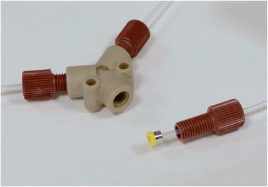
To connect your tubing to other flow accessories, you need to use some good quality fluidic connectors. These come in two parts: a compression-fitting called a ferrule that slips over the end of the tubing and forms a tight seal when mated with a second fluidic component; and a nut, which applies the pressure required to hold the ferrule in place. You should get a clearer idea from Fig. 1, which shows a yellow ferrule that has been slipped onto the end of a piece of PTFE tubing and would normally be held in place by the red nut. Ferrules for plastic tubing are typically made from polyether ether ketone (PEEK) or another chemically resilient plastic, and with care can be slipped from an old piece of tubing to a new one. (You won't find many suppliers encouraging you do this, but reusing ferrules works just fine and will save you a fair amount of money.) Various styles of ferrule exist: we like the ‘Super Flangeless' ones as they stop the tubing from twisting as the nut is screwed in. Ferrules are a sure-fire way of making fast fluidic connections: with practice, you can cobble everything together in a matter of minutes, and you'll still find it's good enough to withstand 30 bar pressures.
To mix two fluid streams, you can use a simple Y-mixer, which is more-or-less exactly what it sounds like: a Y-shaped accessory with two inlets that merge into a single outlet. (You can see a dismantled one in Fig. 1.) You can buy them fairly cheaply from companies like Upchurch or, if you're handy with a mill, can make them yourself. Be sure to choose a material that's compatible with your solvents – PTFE or PEEK are good options. If you pump two miscible solutions into the inlets of your mixer, they'll come together in a laminar fashion and gradually inter-diffuse until they have fully mixed. Here you need to ensure there's a sufficient length of tubing at the outlet to get complete mixing before the next step in your process – something you can calculate or test experimentally.5 Keep the flow-rates reasonably well matched (stay within a factor of ten) or you might find the pumps begin to stutter and the concentration of the mixed solution starts to fluctuate.
If the two liquids you're injecting – let's call them A and B – are immiscible, interesting things happen. When both liquids have a strong affinity for the channel walls, you end up with slug flow where the liquids divide into an alternating train in an ABAB-type manner, see Fig. 2a. (A similar thing happens when you inject a liquid and a gas into the two inlets.) But, if liquid A wets the wall more readily than B, you'll end up with droplet flow, see Fig. 2b. In this case A, which is usually referred to as the carrier liquid, coats the entire channel wall and B forms discrete droplets inside of it. Now let's suppose B is our solvent and A is an inert liquid. In both cases B breaks up into a series of miniature pellets, each of which behaves like a highly uniform microscale reaction vessel – ideally suited to carrying out controlled chemical reactions. But, in the case of droplet flow, B is kept completely isolated from the channel walls, meaning it can never foul the reactor. Who could say fairer than that?
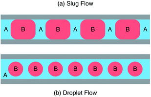 | ||
| Fig. 2 Schematic showing (a) slug flow where two immiscible liquids A and B wet the reactor wall and (b) droplet flow where liquid A wets the wall preferentially, fully encapsulating liquid B. | ||
Fluorocarbons are a good choice for the carrier liquid, especially when you're using FEP or PTFE tubing. They're chemically inert and won't mix with non-fluorous liquids, so you can use either aqueous or organic solvents for the reaction phase. We tend to use perfluorinated polyethers (PFPEs), which are commonly sold as heat transfer fluids for vacuum pumps. (They're also used for the non-stick coatings in pizza boxes. What gives?) Boiling points and viscosities increase with molecular weight. The lower weight PFPEs with boiling points less than 200 °C are the easiest to pump, and the cheapest, costing around $50 per kilogram. These are the ones we normally use. But for high temperature reactions, you'll need something heavier and will find yourself spending at least twice that amount. A bit pricey perhaps but, since they don't take part in the reaction, you can scrub them up afterwards and use them again. That makes them pretty cost-effective in the long run. Low weight PFPEs can be filtered, and then washed with standard lab solvents to remove contaminants. Higher weight grades are too gloopy to filter but can be centrifuged. Once you're done cleaning, purge thoroughly with argon to displace any dissolved gases, and you're ready to go again.
Droplet flow can be tricky to maintain: slight differences in the speeds of the flowing droplets can cause them to come into contact and merge unpredictably. To avoid this, you can use surfactants to help stabilize the droplets. But that's not a great idea when you're doing synthetic chemistry. Instead, try to keep the flow uniform by avoiding kinked tubing and keeping everything nice and horizontal. That way, gravity won't mess with the speed of your droplets and you can keep them apart.
There are lots of ways to heat your reaction mixture, but one of the simplest is to immerse a section of your tubing in an oil bath. Try placing an oil-filled Petri-dish on top of a small hot-plate, using a magnetic stirrer to get a nice uniform temperature distribution – you'll find it cheaper and less cumbersome than a commercial oil-bath. Again make sure your hotplate has a serial port for computer interfacing. Petri-dishes are rather small, so you may find you need to coil your tubing a little to save space. That's OK, but make sure the oil can access every part of the tubing or you'll end up with uneven heating. We often make our own oil dishes with in-built spiral-shaped supports to hold the tubing in place, see Fig. 3. For low temperature applications (<100 °C), we print them out of polylactic acid (PLA), using a hobbyist 3D printer at $5 a pop. (If you have your own printer, you can make one yourself by downloading the .stl file in the ESI‡). For higher temperature applications, you can machine something out of metal or PTFE. Oil-baths can be used for temperatures up to about 300 °C – above that, the oil starts to fume and you should probably switch to some kind of solid-state heater instead. (You'll also want to move from PTFE to stainless steel tubing at those kinds of temperatures.)
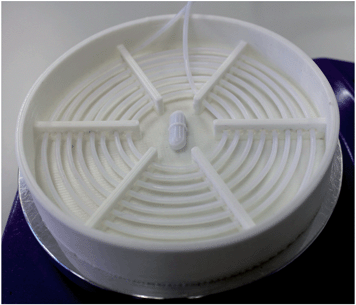 | ||
| Fig. 3 Photograph of a 3D-printed oil bath with integrated mounting holes for holding PTFE tubing in a fixed spiral arrangement. | ||
A lot of batch syntheses are done under reflux at the boiling point of the solvent. This isn't an option with flow reactors as the solvent vapor will mess up the flow characteristics. But, as an alternative, you can work at elevated pressures by placing a back-pressure regulator (BPR) at the tubing outlet. BPRs are simple spring-controlled valves that allow a fluid to flow only when a certain pressure is achieved. With PTFE tubing and decent ferrule-style couplings, you can readily access pressures up to 50 bar. This greatly increases the boiling point of a solvent, allowing you to work at higher temperatures and faster reaction rates. (You can do similar things in a batch reactor, of course, but only if your system is specifically designed to handle the elevated pressures; standard glassware with ground-glass joints won't be up to the job.)
OK, so that's enough on the basics of setting up a flow reactor. How do we go about adapting a standard batch synthesis to flow? Let's take the example of poly(3-alkylthiophene), a trusty workhorse in the field of plastic electronics.6,7 In batch, the reaction typically proceeds in two steps. First, we take our liquid monomer – an asymmetric di-brominated 3-alkylthiophene (1) – and activate it by adding an equivalence of a Grignard reagent. This gives a rough 80![[thin space (1/6-em)]](https://www.rsc.org/images/entities/char_2009.gif) :
:![[thin space (1/6-em)]](https://www.rsc.org/images/entities/char_2009.gif) 20 mixture of two thiophene-Grignard isomers (2a/2b), see Scheme 1. Next, we heat to 55 °C, throw in some (solid) nickel catalyst, and then wait for the majority isomer to polymerise into our product (3). (The other isomer is sterically hindered and to first approximation plays no part in the reaction.) All of this, of course, is usually done in a flask. Finally, we collect over some filter paper and wash with acetone/methanol to yield the crude product.
20 mixture of two thiophene-Grignard isomers (2a/2b), see Scheme 1. Next, we heat to 55 °C, throw in some (solid) nickel catalyst, and then wait for the majority isomer to polymerise into our product (3). (The other isomer is sterically hindered and to first approximation plays no part in the reaction.) All of this, of course, is usually done in a flask. Finally, we collect over some filter paper and wash with acetone/methanol to yield the crude product.
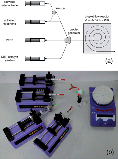
In switching to flow, we need to find suitable flow-based procedures for activating the monomer and performing the polymerisation. The first step is straightforward: all we need is a 3-in/1-out style mixer, similar to the 2-in/1-out Y-mixer described above. You can buy these or make them yourself as you prefer. Into the three inlets we inject our as-received Grignard reagent in tetrahydrofuran (THF), our thiophene monomer, and THF as a diluent – each from its own separate syringe pump. Since the result of this reaction is a mixture of small, soluble molecular species, there is minimal risk of reactor fouling. Providing they're supplied dry and in a suitably purified state, all three components can be loaded directly into the syringes straight-from-the-bottle, taking care to avoid contamination by oxygen and water. Tweak the flow-rates of the three components according to taste, or until you have the exact reagent composition you're after. Of course, if you know what monomer concentration you need in advance, you can prepare the activated monomer beforehand and load it into a single syringe, removing the need for two of the three syringe pumps. That’s the situation we’ve shown depicted in Fig. 5a.
The second step is a bit trickier. Polymers can be sticky, viscous, little things, and producing them in narrow channels is a potential recipe for disaster, especially if you're aiming for high molecular weights. They're liable to coat the wall, and clog the entire channel. Or, if the viscosity gets too high, your solution may simply become too thick to pump, causing excessive back pressures and leakage. Either way, you're in for trouble. To get around these problems, you should switch to droplet flow. That way, the reaction mixture is kept away from the channel walls and can’t cause fouling. And, since you're no longer pumping a continuous stream of high viscosity liquid (but instead transporting discrete droplets inside a flowing carrier fluid), the back-pressure can be kept in check, allowing the liquid stream to be pumped easily even when the molecular weight of the polymer is high. To generate the droplet stream, you can use a second three-way mixer, injecting the activated monomer solution into one inlet, low weight PFPE into the second inlet, and a solution of the nickel catalyst in THF into the third, see Fig. 4a.‡ The outgoing droplet stream passes into an oil bath at 55 °C, where polymerisation begins. You can see this happening in Fig. 4b, with the droplets deepening in colour as they spiral their way through the oil bath. On exiting the oil-bath, you can simply quench the reaction by dropping the entire droplet stream into cold methanol, with the dense PFPE falling to the bottom and your product forming a discrete layer on top of it. Wait for the flow to fully stabilise before you start collecting anything you might actually want to use.
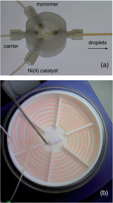 | ||
| Fig. 4 (a) Photograph of a home-made droplet generator (see ESI for a short video of it in action, and a 3D design file. You might also want to check out ref. 8 and 9 for some really easy ways to make droplet generators). Activated monomer solution, PFPE carrier fluid, and a Ni(II) catalyst solution are separately supplied to the three inlets of the mixer, generating a stream of near-identical droplets. (b) Photograph showing growth of poly(3-hexylthiophene) within the tubing. The droplets enter the centre of the spiral with a pale yellow coloration, and change in colour as they pass through the tubing to a deep red (as the polymer inside grows). | ||
The result of doing all this? Exactly what you set out to achieve: the direct transformation of reagents into product without any manual intervention. Is the stuff that comes out any good? Well, judging from the way it performs in electronic devices, it seems to match anything you can buy commercially.6 And the molecular weight distributions are a lot narrower, so the size control is good too. What if you wanted a different the molecular weight? Well, that's controlled by the catalyst to monomer ratio, so all you need to do is change the relative rates at which they're injected into the droplet generator. Simple.
What if you want to make some random copolymers? Well, you can do that too, but you'll need to change the reaction set-up a bit. Remember what we said at the beginning about needing something a bit more flexible than a pre-built commercial system? Disconnect your thiophene syringe from the droplet generator and load a new syringe with a second brominated monomer: we've previously used 3-alkyl selenophene – the selenium-based analogue of thiophene. Now connect the two monomer syringes to the inlets of a Y-shaped mixer, and connect the outlet to the freed-up inlet of the droplet generator, see dotted line in Fig. 5. You're ready to go again. By varying the flow rates of the two monomers you can change the composition of the reaction mixture, and create a series of copolymers that range continuously in stoichiometry from 100% poly(3-alkylthiophene) to 100% poly(3-alkylselenophene).7 It really is that easy.
Hopefully, you get the general idea now and can see how you can go on to perform a broad range of different chemistries in flow. Things aren't always as straightforward as we've implied here, of course. Multistep chemistries involving the sequential addition of multiple reagents can be particularly tricky,10 especially if you're working with droplets. You can certainly do it, but you'll have to consult more erudite articles than this one for a proper explanation. The main message we want to get across here is a simple one. Flow chemistry is a straightforward, easily accessible technology that doesn't require huge expenditure or sophisticated equipment. You can set up a system yourself for a modest outlay, and you'll probably find it performs better than any reactor you could ever buy. Unless, of course, you were to buy one from us.
References
- K. S. Elvira, X. Casadevall i Solvas, R. C. R. Wootton and A. J. de Mello, Nat. Chem., 2013, 5, 905–915 CrossRef CAS PubMed.
- A. B. Theberge, F. Courtois, Y. Schaerli, M. Fischlechner, C. Abell, F. Hollfelder and W. T. S. Huck, Angew. Chem., Int. Ed., 2010, 49, 5846–5868 CrossRef CAS PubMed.
- R. L. Hartman and K. F. Jensen, Lab Chip, 2009, 9, 2495–2507 RSC.
- K. Jähnisch, V. Hessel, H. Löwe and M. Baerns, Angew. Chem., Int. Ed., 2004, 43, 406–446 CrossRef PubMed.
- R. L. Hartman, J. P. McMullen and K. F. Jensen, Angew. Chem., Int. Ed., 2011, 50, 7502–7519 CrossRef CAS PubMed.
- J. H. Bannock, S. H. Krishnadasan, A. M. Nightingale, C. P. Yau, K. Khaw, D. Burkitt, J. J. M. Halls, M. Heeney and J. C. de Mello, Adv. Funct. Mater., 2013, 23, 2123–2129 CrossRef CAS.
- J. H. Bannock, M. Al-Hashimi, S. H. Krishnadasan, J. J. M. Halls, M. Heeney and J. C. de Mello, Mater. Horiz., 2014, 1, 214–218 RSC.
- A. M. Nightingale, S. H. Krishnadasan, D. Berhanu, X. Niu, C. Drury, R. McIntyre, E. Valsami-Jones and J. C. DeMello, Lab Chip, 2011, 11, 1221–1227 RSC.
- E. Quevedo, J. Steinbacher and D. T. McQuade, J. Am. Chem. Soc., 2005, 127, 10498–10499 CrossRef CAS PubMed.
- A. M. Nightingale, T. W. Phillips, J. H. Bannock and J. C. de Mello, Nat. Commun., 2014, 5, 3777 Search PubMed.
Footnotes |
| † With tongues firmly in cheeks, the authors provide a light-hearted tutorial-style guide to the intricacies of do-it-yourself flow chemistry. |
| ‡ Electronic supplementary information (ESI) available. See DOI: 10.1039/c4mh00054d |
| This journal is © The Royal Society of Chemistry 2014 |

