Continuous flow chemistry: where are we now? Recent applications, challenges and limitations
Faith M.
Akwi
 and
Paul
Watts
 *
*
Nelson Mandela University, University Way, Port Elizabeth, 6031, South Africa. E-mail: Paul.Watts@mandela.ac.za
First published on 20th November 2018
Abstract
A general outlook of the changing face of chemical synthesis is provided in this article through recent applications of continuous flow processing in both industry and academia. The benefits, major challenges and limitations associated with the use of this mode of processing are also given due attention as an attempt to put into perspective the current position of continuous flow processing, either as an alternative or potential combinatory technology for batch processing.
1 Introduction
Continuous flow chemistry is defined as an array of chemical processes performed in continuous flowing streams. This kind of chemistry is enabled by the use of micro-reactor technology, which has been and still is the latest buzz technology. Over the years, the application of this technology in many a research niche in academia and manufacturing industries has tremendously grown due to the advantages it presents. These are attributed to their small channel dimensions for example; they enable the use of small volumes of reagents and in turn enable easy and safe handling of hazardous reagents in addition to facilitating continuous synthesis, which eliminates the need to isolate toxic and or hazardous intermediates. Their large surface area to volume ratio, also a result of the small dimensions, provides efficient mass and heat transfer rates.Continuous flow reactors also permit the use of solvents at elevated conditions, which is only possible because the systems can be easily and safely pressurized. Reduced reaction time, enhanced chemical selectivity and improved yields due to efficient mixing and accurate control of reaction parameters are also some of the benefits observed to mention but a few. The question therefore that hangs in a balance is; is micro-reactor technology all that it has been cut out to be? In this review, we present some recent applications of continuous flow processing categorised into the benefits that this kind of processing brings forth. Herein, we also highlight the merits, as well as the challenges, that are still to be addressed.
2 The merits of continuous flow processing in chemical synthesis
2.1 Accurate reaction parameter control
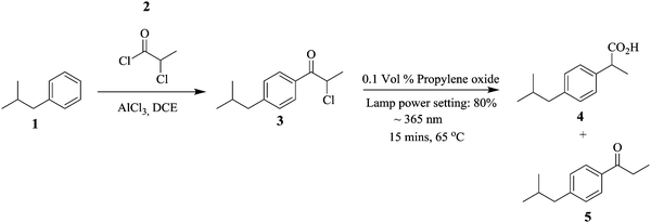
Continuous flow systems have enabled reactions whose processing conditions are difficult to control in batch reactors possible.1–6 For example, photochemical reactions in batch reactors are faced with challenges such as the lack of accurate control of the amount of light needed for a particular reaction. This could lead to decomposition of reactants and/or enable side reactions leading to overall low productivity. In addition, the lack of efficient mixing and heat transfer rates in these reactors further increases the possibility of these occurrences.Micro reactors, as an example of continuous flow systems, due to their small channel dimensions, a structural advantage that provides them with a large surface area to volume ratio, enable efficient and accurate illumination on the reaction substrates in photochemical reactions.7 In fact, the period of reactant exposure to the light source can be controlled by changing the flow rate of the feed reactants.8 Baumann et al. performed a photo-Favorskii rearrangement in the synthesis of Ibuprofen, an anti-inflammatory drug using a Vapourtec E-series flow system in conjunction with its UV-150 photo-reactor.9 The Friedel Craft's acylation of isobutylbenzene 1 and chloropropionyl chloride 2 was done in the presence of AlCl3 (Scheme 1). The intermediate 3 was subjected to conditions (indicated in Scheme 1) to give a ratio of 7![[thin space (1/6-em)]](https://www.rsc.org/images/entities/char_2009.gif) :
:![[thin space (1/6-em)]](https://www.rsc.org/images/entities/char_2009.gif) 81
81![[thin space (1/6-em)]](https://www.rsc.org/images/entities/char_2009.gif) :
:![[thin space (1/6-em)]](https://www.rsc.org/images/entities/char_2009.gif) 12 of intermediate 3, isobutylphenyl propionic acid i.e. ibuprofen 4 and Norrish product 5 respectively. At a 1 mmol scale, 3.65 mmol h−1 of target compound 4 was generated. In this study, precise reaction conditions for the chemical transformation were easily found and could be accurately employed in the synthesis of selected esters. Moreover, the synthesis of ibuprofen was nicely scaled up.
12 of intermediate 3, isobutylphenyl propionic acid i.e. ibuprofen 4 and Norrish product 5 respectively. At a 1 mmol scale, 3.65 mmol h−1 of target compound 4 was generated. In this study, precise reaction conditions for the chemical transformation were easily found and could be accurately employed in the synthesis of selected esters. Moreover, the synthesis of ibuprofen was nicely scaled up.
The large surface area to reactor volume of continuous flow systems was also exploited by Reiser et al. in the synthesis and application of polyisobutylene-tagged fac-Ir(ppy)3 complex as a recyclable visible-light photocatalyst in the isomerization of Z to E-alkenes (Scheme 2). Using a thermomorphic solvent system (TMS) comprising of acetonitrile and heptane, a homogenous reaction system was obtained at a reaction temperature of 90 °C.10 In order to effect a photocatalytic reaction environment, the mixture was irradiated using a blue LED light at 455 nm. A Z/E ratio of 82![[thin space (1/6-em)]](https://www.rsc.org/images/entities/char_2009.gif) :
:![[thin space (1/6-em)]](https://www.rsc.org/images/entities/char_2009.gif) 18 was obtained. At room temperature, a bi-phasic reaction mixture was formed, which enabled simple catalyst recovery and recycle. Furthermore, the iridium concentration in the reaction product was less than 2 ppm. For easy transfer of the developed continuous flow synthesis procedure to other photochemical reactions, the reaction was investigated at room temperature in micro reactors. There was no diminished chemical reactivity observed in the process even at room temperature. Most importantly, there was no significant change in the Z/E ratio of the products (ranging between 83
18 was obtained. At room temperature, a bi-phasic reaction mixture was formed, which enabled simple catalyst recovery and recycle. Furthermore, the iridium concentration in the reaction product was less than 2 ppm. For easy transfer of the developed continuous flow synthesis procedure to other photochemical reactions, the reaction was investigated at room temperature in micro reactors. There was no diminished chemical reactivity observed in the process even at room temperature. Most importantly, there was no significant change in the Z/E ratio of the products (ranging between 83![[thin space (1/6-em)]](https://www.rsc.org/images/entities/char_2009.gif) :
:![[thin space (1/6-em)]](https://www.rsc.org/images/entities/char_2009.gif) 17 and 81
17 and 81![[thin space (1/6-em)]](https://www.rsc.org/images/entities/char_2009.gif) :
:![[thin space (1/6-em)]](https://www.rsc.org/images/entities/char_2009.gif) 19). It should be noted that at room temperature, the thermomorphic solvent system formed a biphasic mixture. This did not have significant impact on the reaction since the large surface area to volume ratio provided by the micro-reactor reaction space enabled the reaction to happen at the liquid–liquid interphase, however lower flow rates were required (10 μmol min−1) as opposed to that at higher temperatures (20 μmol min−1).
19). It should be noted that at room temperature, the thermomorphic solvent system formed a biphasic mixture. This did not have significant impact on the reaction since the large surface area to volume ratio provided by the micro-reactor reaction space enabled the reaction to happen at the liquid–liquid interphase, however lower flow rates were required (10 μmol min−1) as opposed to that at higher temperatures (20 μmol min−1).
The authors also explored a deiodination reaction incorporating the recycling of polyisobutylene-tagged fac-Ir(ppy)3 in micro reactors (Scheme 3). At a reaction temperature of 85 °C, the first run gave 64% yield of target compound of which 17% was due to the product that was extracted from the heptane phase of the last run.
The synthesis of poly(3-hexylthiophene) 13 by Grignard metathesis polymerization in droplet based flow reactors is reported by Bannock et al. where Ni(dpp)Br2 was used as a catalyst which was generated in situ in an argon atmosphere.11 The use of the droplet based flow; using perfluorinated polyether as carrier fluid in polytetrafluoroethylene tubing eliminated fouling, a common problem observed in polymerization reactions (Scheme 4). 2-MeTHF was the solvent of choice, which enabled an increase in reaction temperature (65 °C) slightly above that commonly used with THF as a solvent (55 °C). Full conversion was achieved in less than 1 minute, moreover an average molecular weight of 44 kg mol−1 was obtained from the flow synthesis i.e. low molecular weight polymers compared to those attained from the batch synthesis. What is more is that, this is a characteristic of polymers synthesised from non-chlorinated solvent. The batch synthesis using 2-MeTHF at 75 °C gave a yield of 85% and a molecular weight of 134 kg mol−1.
Andrade et al. illustrated a high throughput continuous flow process for the synthesis of chiral amines from asymmetrical amination of ketones using ω-transaminase/pyrodoxal 5′ phosphate (ω-TA/PLP) and E. coli cells loaded on methacrylate beads as the biocatalyst.12 The amination of 2,5-benzyloxyacetone 15 with isopropylamine 14 in a packed bed reactor at 50 °C provided a yield of 79% mexiletine 16 in 30 minutes reaction time (Scheme 5). On continuous operation of the process for 5 days in a reactor volume of 0.5 mL and reaction temperature of 50 °C, the activity of the enzymatic catalyst decreased by <10% with the same enantioselectivity (>99% ee) observed. The system was also operated for 10 days at a decreased reaction temperature and increased residence time (30 °C and 60 minutes respectively). Similar results were attained as in the 5-day continuous process operation thus confirming that the short reaction time of 30 minutes and lower reaction temperature of 50 °C were sufficient enough to give high throughput of amine 16. An isolation step was also effortlessly included in this process.
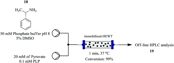
Plantchestainer et al., on the other hand exploited a cell-free immobilized (S)-selective amine transaminase from Halomonas elongate for the synthesis of amines in a continuous flow reaction set up.13 This protocol (Fig. 1) enables protein stability towards high temperatures, pH levels and organic solvents. This was observed with the enzyme immobilized on metal derivatised epoxy sepa beads; nearly 90% preserved activity after storage in buffer for 30 days at 4 °C and pH 8. An increased tolerance to organic solvents and usability was also seen. From the model reaction between pyruvate and (S)-(−)-L-phenylethylamine as an amino donor at 37 °C, atmospheric pressure, 5 mg of enzyme per gram of resin and DMSO as a co-solvent, 99% conversion was achieved in a residence time of 1 minute. In batch, 50 mg resin in 0.5 mL reaction volume gave full conversion in 180 minutes. The efficient heat and mass transfer in the flow set up, accelerated the bioconversion rate compared to the batch set up.
Bisalkylation of cyclopentadiene 21 with 1,2-dichloroethane 22 to give spiro[2.4]hepta-4,6-diene 23, is a highly exothermic reaction that can only be performed efficiently by controlled dossing of the base; concentrated sodium hydroxide i.e. semi-batch mode of synthesis since temperature control is very important (Scheme 6). Kilcher et al. have managed to transfer this synthesis to a continuous flow system comprising of a T-mixer and two self-made Raschig ring static mixers. A yield of 95% at 20 °C, 40 °C and 60 °C reaction temperatures of the three mixers respectively was obtained in 25 minutes.14 19.8 g of desired compound was produced in 1.3 hours. The diene 23 was safely generated in the flow reactor system, which provided efficient mixing and temperature control. Compared to the batch reaction, a yield of 78% was obtained in a total reaction time of 1.5 hours.
Rulliere et al., in their study involving the in-flow generation of difluorocarbene and its consequent addition to alkenes and alkynes to form difluorocyclopropanes and difluorocyclopropenes, were similarly able to demonstrate how the use of micro-reactor technology enables the precise control of reaction parameters.15 The transformation involves the use of high temperature and pressure of which these two reaction parameters are seldom controlled efficiently in batch synthesis. The group was able to perform this synthesis in continuous flow where 24 was transformed into 25 in only 10 minutes (Scheme 7). Compared to the batch synthesis of 25, this synthesis proved to be less time consuming, safe and high yielding.
Continuous flow processing has also been applied in the production of nanoparticles. It has also been reported to improve the physical properties and characteristics of the nanoparticles, increase throughput, offer narrow size distribution of particles and most importantly reproducibility.16–22 For example, Thiele et al. demonstrate the advantages of employing a Dean-flow mixer, a glass microfluidic device with two inlets and one outlet (depth: 0.1 mm, width: 0.05 mm and length: 6.112 mm) for the synthesis of gold nano-cubes over the conventional batch process.23 The microfluidic synthesis was shown to have higher reproducibility due to the accurate control of incubation times, which was easily enabled through manipulation of residence channel lengths and efficient mixing. An optimum incubation time of 7 seconds, for the first growth solution, is reported to be sufficient for the production of nano-cubes with well-defined shaped. The Dean-flow mixer microfluidic system also enabled a lower consumption of starting material since a specific amount of first growth solution can be activated when needed, thus generating less waste of activated unused growth solution which is a problem in the batch synthesis. Furthermore, by using the microfluidic synthesis approach, the effect of the counter ions on the morphology and shape of the nano-structures was rapidly investigated with ease in less than 30 minutes. The presence and concentration of sodium bromide in the second growth solution was found to be crucial in predetermining the shape and morphology of the gold nano-structures. It was found that between 25 and 50 μM of sodium bromide, a transition from nano-cubes to nano-rods was observed.
2.2 Reduced reaction times
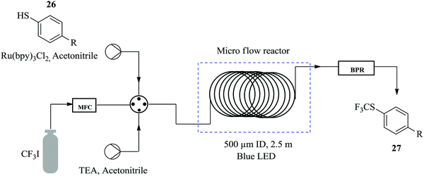
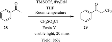
Straathof et al. demonstrate how a continuous flow process of the photocatalytic trifluoromethylation of thiols reduces the amount of reagent required and shortens the reaction time compared to the batch process.24 In the presence of inexpensive CF3 source, namely CFI3 and photocatalyst; Ru(bpy)3Cl2, the trifluoromethylation of thiophenol 26 to form 27 (Fig. 2) was performed in 1 minute with 98% yield attained. The same reaction was also carried out in batch where comparable yield was attained in 30 minutes. The remarkable cut in reaction time observed in the flow trifluoromethylation is ascribed to the efficient mixing in the slug flow pattern formed in the continuous flow process hence enhancing the reaction rate. Additionally, it was also found that a slight excess of CFI3 (1.1 eq.) compared to the batch synthesis (4 eq.) was needed. It was also shown how perfluoroalkyl analogues could easily be prepared within 1 hour using this method. Excellent yields ranging from 75–91% were observed.Similarly in the continuous flow photocatalytic α-trifluoromethylation of acetophenone 28 under conditions shown in Scheme 8, a short reaction time of 20 minutes was sufficient to provide a high yield of 86% (93% conversion) while in the batch synthesis, it took a total of 30 minutes to achieve a conversion of 85% at similar reaction conditions. What is more is that a cheaper photo redox catalyst Eosin Y and iPr2EtN as base was used in the continuous flow synthesis.
Previously, Chen et al. had reported a trifluoromethylation of aromatic and heteroaromatic compounds using potassium trifluoroacetate as CF3 source in continuous flow systems.25 To demonstrate; using CF3CO2K as source of CF3, CuI in NMP with pyridine as a ligand, 4-iodobiphenyl 30 was transformed to 4-trifluoromethylbiphenyl 31 in only 16 minutes at a reaction temperature of 200 °C (Scheme 9). The developed method, exhibited very high selectivity towards the desired product. An investigation of the substrate scope of the flow conditions showed good tolerance to para, meta and ortho substituted substrates (yield of isolated product: 81–96%) in addition to electron deficient, rich and neutral substrates (yield of isolated products: 63–91%).
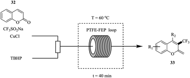
Zhang et al. in contrast, reported the use of Langlois reagent (CF3SO2Na), a cheap and stable source of CF3 for the continuous flow trifluoromethylation of coumarins (Fig. 3).26
Shorter reaction times (40 minutes) were observed in flow compared to the batch trifluoromethylation syntheses. Notably, a smaller amount of CF3SO2Na (0.8 mmol to 0.4 mmol of coumarin) was required in the flow experiments. The flow conditions were also found to do well with a wide range of coumarins (Scheme 10). The synthesis of 34 was shown to be scalable in the continuous flow system; at five-fold increase in concentration, 1.22 kg was obtained in 240 minutes.
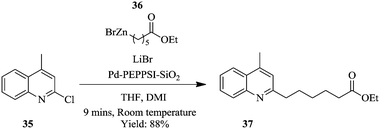
Negishi cross-coupling, using a silica supported Pd–PEPPSI–IPr precatalyst in flow has been reported to require shorter reaction times compared to the batch synthesis.27 The cross coupling of N-heterocycle chlorides such as 2-chloromethyl-4-quinoline 35 with (6-ethoxy-6-oxohexyl)zinc(II)) bromide 36 using Pd–PEPPSI catalyst supported on silica gel at room temperature provided product 37 in 9 minutes (Scheme 11). The same reaction in a batch set-up, under the similar conditions, took 16 hours with 80% yield of product 37. The catalyst's performance was excellent and provided good yields in the Negishi cross-couplings of various N-heterocycle chlorides with various functionalized alkyl zinc reagents. Despite the fact that, catalyst leaching was observed as evidenced from the slow decrease in conversions (100% to 85%) over a period of 15 hours, the leached material showed no catalytic activity. In the batch synthesis set-up, the catalyst could be recycled up to five times with minimum loss in activity reported.
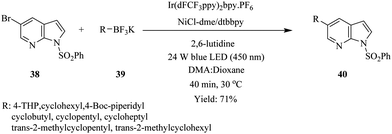
As in the above example, the use of continuous flow led to the acceleration of the synthesis of cyclo alkyl substituted 7-azaindoles via photoredox nickel dual catalytic cross coupling (Scheme 12).28 Benzenesulfonyl protected 5-bromo 7-azaindole 38 was treated with potassium THP trifluoroborate 39 in a continuous flow system under conditions summarised in Scheme 12. The cyclo alkyl substituted 7-azaindoles 40 were generated in 17–71% yield in 40 minutes. The batch reactions were also recorded to have taken longer in addition to providing very low yields. Here, the continuous flow synthesis provided uniform irradiation of reactants at a specific time, which therefore eliminated any chance of over irradiation that could lead to by-product formation and reduction of reaction output. This advantage is attributed to the high surface area to volume of the micro reactors.
Similarly, Petersen et al. have also demonstrated the superiority of the continuous flow synthesis of magnesiated heterocycles and acrylates compared to their batch synthesis.29 The continuous flow synthesis was decorated with very short reaction times, high yields, selectivities and very good functional group tolerance. Additionally, very low reaction temperatures were not needed for the continuous flow synthesis of most of the compounds presented in their work even though this was the case in their batch synthesis. For example, tetra substituted pyridine 43 was easily generated in total reaction time of 1.5 minutes at room temperature from a two-step flow protocol (Scheme 13). The magnesiation of pyridine derivative 41 using TMPMgCl·LiCl and iodolysis to form 43 at room temperature gave 80% yield.
In contrast, the batch protocol of the synthesis required −40 °C and 2 hours to generate the magnesiated intermediate 41 which was quenched by the iodolysis reaction at a temperature range of −40 °C to 25 °C forming only 56% of tetra-substituted pyridine 42. Knochel et al. have also reported similar work where the metalations of acrylonitriles, acrylates and nitroolefins in continuous flow with magnesiation performed in short residence times in the range of 1–20 minutes at near ambient temperature using TMPMgCl·LiCl. The zincation reactions were successfully carried out using TMPZnCl·LiCl at reaction temperatures ≤90 °C. Some other syntheses that have also benefited from continuous flow synthesis protocol in regard to this aspect are found in ref. 30–33.
2.3 Excellent yields and selectivity
The optimization of reaction parameters in continuous flow processing is not as tedious and is a very flexible process compared to batch processing. What is more is that a number of parameters can be optimized in one go in the shortest time possible.34,35 For chemical reactions with multiple products and selectivity issues,36,37 it is often easier to tweak reaction conditions in flow than in batch in order to optimize the production of the desired product.38–41 This is demonstrated in the oxidative coupling of amines using solid acid catalysts.42 The efficiency of individual (CeO2) and combinations of solid acid catalysts (CeO2–MoO3 and CeO2–WO3), supported (CeO2–MoO3/SiO2 and CeO2–WO3/SiO2) and unsupported was investigated using the oxidative coupling of benzylamine 44 as a model reaction.In addition, the effects of temperature and flow rate of the feed were also investigated. As can be seen in this reaction (Scheme 14), there is the production of benzaldehyde 46 and benzonitrile 47 as by-products. Selectivity towards the target compound, N-benzylbenzaldimine 45 is an issue. Suitable reaction conditions that addressed the selectivity issue were established in flow. CeO2–MoO3 catalyst supported on SiO2 was found to be the best catalyst for the reaction. At a reaction temperature of 493 K, feed flow rate of 1 mL h−1, and oxygen bubbled at a rate of 60 mL min−1, 97.8% selectivity towards N-benzylbenzaldimine 45 was achieved in 1 hour. This remained almost unchanged after 6 hours (96%). The oxidative coupling of dibenzylamine under similar reaction conditions also provided good selectivity towards dibenzylimine, which in fact increased over time (1 hour: 65.6%, 6 hours: 81.3%).
Jong et al. also smartly exploited the ability of flow synthesis to provide good reaction selectivity through accurate reaction parameter control43 in the synthesis of mono-protected aliphatic diamines. The synthesis requires careful parameter control otherwise a mixture of protected products is obtained. Efficient mixing is essential for the generation of desired products in good yields. Of the PTFE flow reactor (volume: 2 mL) internal diameters (0.5, 1 and 1.6 mm) investigated, a reactor internal diameter of 0.5 mm gave the best result at a reaction temperature of 0 °C. 1,6-Diaminohexane 47 yielded Boc protected diamines 48 and 49 in the ratio of 84![[thin space (1/6-em)]](https://www.rsc.org/images/entities/char_2009.gif) :
:![[thin space (1/6-em)]](https://www.rsc.org/images/entities/char_2009.gif) 16 respectively in 1 minute (Scheme 15). Using the synthesis of mono-N-Boc-1,6-diaminohexane as their model reaction, the optimum reaction conditions were used to synthesize various mono-protected aliphatic diamines (N-Boc, N-Fmoc and N-Ddiv) in a continuous flow fashion. Excellent yields ranging between 45–91% were obtained. Mono-protected diamines were efficaciously synthesized in flow without the use of chemical auxiliaries.
16 respectively in 1 minute (Scheme 15). Using the synthesis of mono-N-Boc-1,6-diaminohexane as their model reaction, the optimum reaction conditions were used to synthesize various mono-protected aliphatic diamines (N-Boc, N-Fmoc and N-Ddiv) in a continuous flow fashion. Excellent yields ranging between 45–91% were obtained. Mono-protected diamines were efficaciously synthesized in flow without the use of chemical auxiliaries.
Ushakov et al. reported on a continuous flow process for the oxidative cyanation of primary and secondary amines using singlet oxygen. The two-step process comprised of the oxidation of amine and its subsequent nucleophilic addition to form α-aminonitriles as shown in Fig. 4 below.44
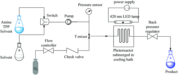 | ||
| Fig. 4 Continuous flow set up for the oxidative cyanation of primary and secondary amines using singlet oxygen. | ||
Excellent yields of α-aminonitriles in the range of 71–99% were observed in 90 seconds when primary and secondary amines were used as substrates however, primary amines were found to first undergo oxidative coupling to form N-substituted imines prior to the formation of the corresponding nitriles. A protocol that avoided the oxidative coupling was thus developed. This was rapidly established in a continuous flow set up. It was found that at lower photo oxidation temperatures (−50 °C), the amine is given time to oxidize to completion, moreover the rate of nucleophilic addition is also slowed down therefore enabling the formation of primary α-aminonitriles. Furthermore, the use of a sub-stoichiometric amount of TBAF (4 mole% relative to TMSCN), was found to increase the yields of the desired compounds (Scheme 16). This is a typical example showing the flexibility of continuous flow processing and how it has been utilized for efficient modification of reaction parameters, which in turn enabled rapid development of a new reaction process towards a desired chemical transformation.
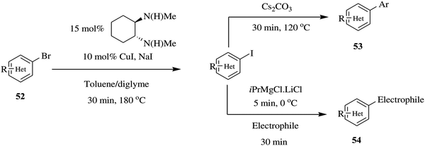
Equally, Chen et al. reported a flexible continuous flow copper catalysed Finkelstein reaction of heteroaromatics to generate aryl iodides where two additional reactions i.e. amidation and Mg–I exchange/nucleophilic addition reactions were elegantly telescoped without isolation of the aryl iodides.45 The Finkelstein reaction provided reaction conversions ranging between 87% and 95% in a reaction time of 30 minutes using a combination of toluene:diglyme as solvent. In comparison, the batch synthesis (130 °C, 5 mol% CuI) gave 34% conversion in the same reaction time. The optimized Finkelstein reaction was immune to para, meta, ortho aryl substrates in addition to electron rich, neutral and deficient bromo arenes. The conditions were also able to withstand sensitive functional groups such as ketones, nitro, chlorine amide, nitrile, sulfonamide and ester groups. This is particularly important for both amidation and Mg–I exchange reactions since the reactivity of aryl bromides is much lower than aryl iodides in both reactions. This protocol provided the reactive aryl iodides that are readily furnished to various amides in quantitative yields (80–96% in 30 minutes). Similarly, in Mg–I exchange reactions; the aryl iodides are more reactive and very tolerant to functional groups than aryl bromides and are thus better suited for this kind of reaction. High yields (72 and 75%) were attained in a period of 35 minutes. In this set up, these species were readily availed to take part in subsequent chemical reactions without isolation (Scheme 17). To summarise, a one-step Finkelstein reaction in addition to two multi-step reactions were rapidly developed in a continuous flow set up.
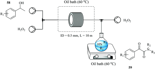
A two-step process for the synthesis of α-ketoamides from secondary benzylic alcohols using hydrogen peroxide as an oxidant has been developed in a continuous flow reactor46 wherein short reaction times, improved yields and increased functional group tolerance were observed (Fig. 5). After a series of investigations on the sequential addition of reactants in a batch reactor, it was found that in order to achieve high yield, potassium iodide, 1-phenylethanol 55, sulphuric acid, hydrogen peroxide in DMF had to be stirred at 70 °C for 12 hours after which 1-oxa-4-azacyclohexane 56 was added. Hydrogen peroxide was thereafter added using a syringe within a period of 2 hours to generate desired α-ketoamide compound in 95% yield. The continuous flow approach devised to mimic the batch protocol shortened this reaction time to only 3 minutes (Scheme 18). It also enabled the efficient and timely addition of the hydrogen peroxide with a syringe pump.
The approach was extended to the synthesis of α-amino ketones (Fig. 5) where the process performed equally well with excellent tolerance to functional groups and high reaction yields in the range of 41–91% observed for acyclic and cyclic secondary amines with the latter showing higher reactivity than the former. It is also noteworthy that no product was obtained from the reaction with primary amines.
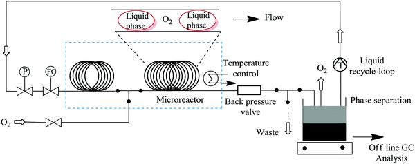
Bay et al. have illustrated the safe synthesis of oxazole 62 using molecular oxygen in a structured micro reactor (Fig. 6).47 The set up also enabled the continuous flow reduction of oxazole peroxide 61 to oxazole methyl alcohol 62. Besides providing a safe process for this high pressure and temperature chemical synthesis involving molecular oxygen, in a reaction time of 240 minutes oxazole 62 was formed in 90% yield. The batch synthesis is reported to take 48 hours with conversion >95%. Furthermore, a liquid recycle loop was added onto the continuous flow set up, something that is not possible in conventional batch processing. The scalability of the established flow process using a reactor volume of 34.6 mL, at similar reaction conditions, was also shown to be feasible (Scheme 19).
2.4 Process intensification
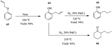
Process intensification is described as a strategy used to achieve tremendous reductions in plant size at a particular plant volume.48 This chemical engineering concept was first developed in the 1970's and has since then been employed to reduce environmental impact49 of chemical processes as well as improve yield50,51 and conversion in chemical processes,52 a potential step towards green chemistry. Continuous flow systems have also been exploited as tools to effect process intensification in chemical synthesis processes.53–58 Recently, Ouchi et al. demonstrated how a small footprint reactor was used to effect process intensification in the synthesis of 2-propyl phenol 65 and 2-propyl hexanone 66 under solvent free continuous flow conditions (Scheme 20).59The Claisen rearrangement of allyl phenyl ether 63 was performed in a Pheonix (ThalesNano) system at 320 °C in a reactor column volume of 1 mL, which gave 94% yield in a residence time of 1 minute and 60 g h−1 of intermediate 64. On further intensification using an 8 mL reaction coil, it was found that the throughput increased linearly as well (480 g h−1). These results are important in a sense that they are indicative of the feasibility of scaling up the process which is usually a bottleneck in most batch processes. This was equally investigated for the reduction step by increasing the catalyst loading (10% to 20% Pd/C). The throughput was found to increase from 80 g h−1 to 120 g h−1 but on increasing reactor coil volume from 3 mL to 12 mL, no significant improvement in the throughput was observed. The two reaction steps were successfully combined forming compounds 65 and 66 with no downstream processing in high yields; 94% and 93% respectively.
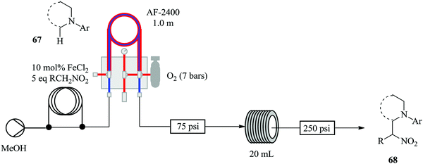
Brzozowski et al., with the use of a microporous gas permeable material; Teflon AF-2400, have demonstrated the process intensification of a nitro-Mannich type direct α-C(sp3)–H functionalisation of N-aryl-1,2,3,4-tetrahydroisoquinolines catalysed by iron salts and oxygen as the terminal oxidant in a continuous flow process (Fig. 7).60
The aerobic nitro-Mannich reaction of N-phenyl tetrahydroisoquinoline was used a model reaction for the investigation. The authors report that no side products were observed by TLC or 1H-NMR. This chemical synthesis was indeed enhanced in continuous flow as was hypothesized prior to the study. The optimized conditions, in the presence of 2 eq. Et3N at 90 °C were used for the continuous flow aerobic nitro-Mannich reaction involving different substrates i.e. electron withdrawing and rich substituents. Mildly electron withdrawing substrates gave nitro Mannich products in good yields (31–77%). A similar observation was made with the electron rich alkyl or ether substituted N-aryl groups (yield ranging between 54–73%). ortho-Fluorine substitution of the N-aryl ring slowed down the reaction and generated a side product. Strongly electron withdrawing substituted substrates on the other hand gave no product.
2.5 Enhanced process safety
Epoxidation reactions, though very important in the synthesis of key intermediates, also leads to the formation of explosive compounds i.e. epoxides and peroxides thus rendering it problematic to perform in batch reactors. Wei He et al. were able to synthesize m-chloroperbenzoic acid and immediately furnished it with cyclohexene to form cyclohexene oxide.61 Cyclohexene oxide 72 was synthesised in a continuous flow system from the peroxidation of m-chlorobenzoyl chloride 69 in the presence of hydrogen peroxide and potassium peroxide to form m-chloroperbenzoic acid 70 in 74% yield. The effluent was then acidified and reacted with cyclohexene 71 to form the desired cyclohexene oxide 72 (Scheme 21). This is yet another example of an organic synthesis where micro-reactor technology has enabled the in situ generation of rather important intermediates. 100% conversion was achieved in a total residence time 10.5 minutes and most importantly, the m-chloroperbenzoic acid that was generated in situ, was used without further purification.Jolhe et al. has explored the synthesis of performic acid (PFA) in continuous flow micro-structured reactors.62 Since PFA is highly unstable, its synthesis in batch reactors leads to very low yields. This is attributed to the long reaction time required which eventually leads to the decomposition of the formed PFA. In addition, control of reaction temperature, in these reactors is always a problem, uneven heat distribution and hot spots are common. Continuous flow reactors were used to alleviate some of the challenges faced in the batch synthesis. In the presence of Amberlist IR-120H catalyst (471 mg cm−3), at a total flow rate of 50 mL h−1 for hydrogen peroxide and formic acid (molar ratio 1![[thin space (1/6-em)]](https://www.rsc.org/images/entities/char_2009.gif) :
:![[thin space (1/6-em)]](https://www.rsc.org/images/entities/char_2009.gif) 1), and reaction temperature of 40 °C under ultrasonic irradiation, the continuous flow synthesis of PFA (approximately 3.5 mol L−1) was successfully achieved in only 10 minutes.
1), and reaction temperature of 40 °C under ultrasonic irradiation, the continuous flow synthesis of PFA (approximately 3.5 mol L−1) was successfully achieved in only 10 minutes.
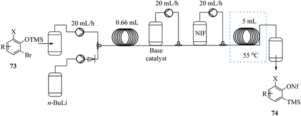
Boris et al. demonstrates the possibility of generating trimethylsilylphenyl perfluorosulfonate benzyne precursors in continuous flow (Fig. 8).63 The problematic side reactions of n-BuLi initiated retro-Brook step were by-passed. Additionally, the tedious silica chromatography purification of products was not required. The continuous flow synthesis also limited operator exposure to the toxic and sensitive chemicals.
Since the n-BuLi decomposed in THF at room temperature, a two solvent system consisting of THF and diethyl ether was used. Substrates were dissolved in diethyl ether while the n-BuLi was kept in THF. As such, the reaction was successfully pushed forward. Reaction yields of the homologous Kobayashi type benzyne precursors in the range of 75–97% were obtained in 30 minutes. The authors also considered the synthesis of nonaflate aryne precursors such as 76 in Scheme 22 below on conjecture that their developed continuous flow process if slightly modified would fit this chemical transformation. On investigation, amine bases were found to promote the reaction and the precursors were synthesized in high yields (82–93%). The group thereafter used the synthesized nonaflate precursors for various aryne chemical transformations e.g. synthesis of 78 ultimately validating the need for the efficient synthesis of these important precursors.
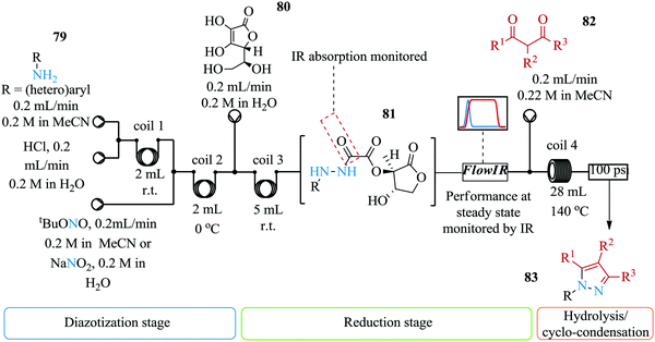
The synthesis of pyrazoles involves the cyclo-condensation of hydrazines. These intermediates are highly toxic and unstable yet they are required for this synthesis. Furthermore, for safe handling of these compounds, the said intermediates should be in solution i.e. their isolation is not a viable option. Poh et al. introduce a multi-step continuous flow synthesis of pyrazoles via a metal free amine-redox process (Fig. 9).64 This is a useful synthesis route and approach for the synthesis of pyrazoles compared to previous routes and approaches reported in literature. Firstly, the storage of the highly unstable intermediate; hydrazine is not required and as such, process safety is ensured. Secondly, the continuous flow synthesis enabled rapid screening of reaction parameters as is demonstrated by Poh et al. Reaction parameter screening of the synthesis showed that the final yield of pyrazole 83 was dependent on the residence time of the reduction step i.e. longer residence times resulted into decomposition of hydrazide. Temperatures higher than 140 °C for reaction coil 4 resulted in reduced yield of pyrazole. The authors thereafter successfully telescoped the four step synthesis. Electron withdrawing substituted anilines provided good yields (45–69%). 1,3-Dicarbonyl substrates also gave relatively good yield (57–69%).
Comas-Barcelo et al. have also recently reported a copper catalysed synthesis of 1,4-di-substituted pyrazoles via the cycloaddition reaction of sydnones and terminal alkynes (Fig. 10).65 In a reaction time of 5 minutes at 140 °C reaction temperature, conversions of 24–100% were achieved for a range of phenyl, p-methoxymethyl, benzyl substituted pyrazoles. This is much shorter compared to the batch synthesis. On the other hand, low yields for alcohol containing pyrazoles were observed (<40%). This was attributed to the high temperatures required over a long period, which led to decomposition of the pyrazole. The activity of the catalyst was also tested and it was found that after a continuous operation period of 4–5 hours, there was no decrease in conversion moreover, pure products were attained. A simplified one feed scale up of the continuous synthesis in 2 mL HPLC columns at similar reaction conditions gave 36 mg of 87 after 2 hours and 72 mg of 88 in 5 hours. It should be noted that the previous conditions had not been optimized for this kind of set up.
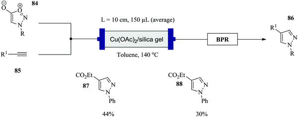 | ||
| Fig. 10 Continuous flow synthesis of 1,4-di-substituted pyrazoles via cycloaddition of sydnones and terminal alkynes. | ||
The safe synthesis of triazoles via a telescoped 3-step process i.e. diazotization, azidodediazotization and copper catalysed alkyne–azide cycloaddition sequence in a three reactor process was shown by Teci et al.66 The highly unstable diazonium salt intermediate generated from the diazotization of an array of anilines (Fig. 11 above) was immediately treated with sodium azide without isolation to form an azide derivative in the azidodediazotization reaction which was performed at room temperature. The crude aryl azide was thereafter flowed and subjected to copper catalysed alkyne–azide cycloaddition conditions at 60 °C. Two methods with different conditions were employed. Using Method A (Fig. 11), chloro, nitro, trifluoromethyl, alkylthio, ester, sulphonamide substituted anilines, electron rich substrates as well as hindered anilines were well tolerated and all gave good yields (73–85%). Some issues with insolubility of products were encountered which prompted the use of Method B. This dilution in reagent streams still worked well with high product yields obtained. A step was taken further to explore the synthesis of other triazole derivatives from alternative dipolarophiles which provided products in very good yields (72–83%).
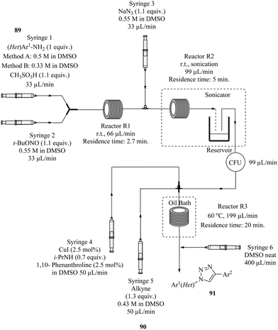 | ||
| Fig. 11 A telescoped 3-step process for the synthesis of triazoles via diazotization, azidodediazotization and copper catalysed alkyne–azide cycloaddition. | ||
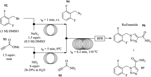
Similarly, Zhang et al. used [3+2] Huisgen cycloaddition in the synthesis of rufinamide 96, a heterocycle containing a 1,2,3-triazole system in a continuous flow set up.67 Azide 94 was generated in situ from benzyl bromine derivative 92 in 1 minute at room temperature thus eliminating the need for its isolation (Fig. 12). Additionally, the propiolamide 95, was generated in situ from methyl propiolate 93 in 5 minutes. The two steps were combined to partake in the copper tubing catalysed amidation of azide 94 which was successfully achieved in 6.2 minutes providing a 92% yield of the target compound 96.
Otvos et al. reported similar work where a bimetallic catalyst (Cu–Fe) and scavenger (Fe) were used in azide–alkyne cycloaddition reactions in a continuous flow system.68 The batch synthesis of this reaction using Cu–Fe catalyst in the absence of a scavenger with stirring at 30 °C and at 1 bar gave an isolated yield of 98% in 8 hours. A scavenger was employed to cab the leaching of catalyst that would lead to impure products. In addition, it was discovered that high temperatures improved reaction conversions however, since azides are unstable and hazardous, a protocol that avoided the use of such reaction conditions was devised.
As a model reaction, the cycloaddition of benzyl azide 98 to phenylacetalyne 99 at ambient temperature, using Cu/Fe catalyst to form triazole 100, was achieved in a flow reactor in 1.5 minutes (Scheme 23). The use of acetic acid and diisopropylethylamine as additives proved to be essential in improving the reaction conversions further. Notably, the copper scavenger used was found to not only reduce the amount of copper leaching but also act as a source for the in situ regeneration of the bimetallic catalyst Cu/Fe. The catalyst's activity did not diminish in 150 minutes; however it was found that the scavenger needed to be replaced after 2.5 hours. A library of compounds were synthesised in good yields using similar conditions. Aliphatic and aromatic azides with either electron withdrawing or donating substituents were tolerated (yield: >94%) in addition to linear, branched, cyclic and unsaturated non-aromatic azides (yield: >93%). Non-aromatic alkynes such as propargyl acetate, ethyl propiolate and pent-1-yne also performed exceptionally resulting into high yields (75–98%) of triazoles. In summary, a safe process was established for the synthesis of an array of triazoles.
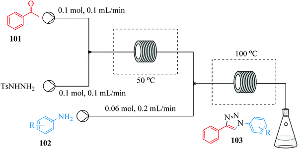
Thus far, the above examples showcase the use of metal catalysts and organic azides to effect the synthesis of 1,4 disubstituted 1,2,3 triazoles. Gu et al. on the other hand, introduces a metal catalyst and organic azide free continuous flow synthesis of 1,2,3 triazoles (Fig. 13).69 A combination of I2 (0.005 M) and tert-butyl hydroperoxide (0.1 M) at reaction temperatures of 50 °C and 100 °C for step 1 and 2 respectively was used for the synthesis. Yields ranging between 72–85% were obtained in the transformation of aniline and 4 substituted-anilines to a number of 1,4 di-substituted 1,2,3 triazoles. Similarly fluoro, bromo, thiophenyl, furyl and chloro groups could be tolerated. Additionally, sterically hindered substrates, electron deficient and electron rich substituents also gave excellent yield.
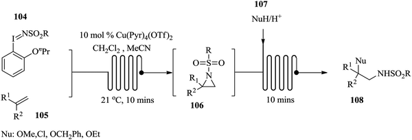
Hsueh et al. recently developed a telescoped continuous flow process for the synthesis of functionalized alkenes via the arizidination route (Fig. 14).70 The arizidines were synthesised from soluble iminoiodanes 104 and alkenes 105 using tetrakis(pyridine)copper(II)triflate as a catalyst. After a period of 10 minutes, the desired aziridine formed 106. Without any isolation of the arizidines, nucleophiles 107 were introduced to generate an array of amine derivatives 108 in excellent yield. In this study, the worker exposure and handling of the toxic, highly hazardous and reactive aziridine intermediates were eliminated since their isolation was not required in this telescoped reaction synthesis. The telescoped continuous flow synthesis worked well with variation in alkenes, nucleophile and iminoiodane. To demonstrate the robustness of this process, the flow synthesis of imidazolines was explored. The ring expansion was effected with the use of boron trifluoride as a catalyst. This chemical transformation took only 20 minutes. The presence of electron withdrawing groups on the alkene seemed not to have any effect on the product yield, thus confirming the robustness of the process (yields: 70–77%).
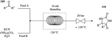
The chemical synthesis of hydantoins in batch reactors has been reported to be a bit problematic, with very low conversions and a multitude of safety concerns observed. This synthesis involves heating an aqueous solution of potassium cyanide, which is potentially very risky with regard to safety especially on a large scale. Furthermore, the relatively high temperatures that are required for the process are inefficiently controlled and maintained in these reactors. The reaction also involves the evolution of ammonia and carbon dioxide gases that are essential for the chemical transformation. Monteiro et al. have successfully displayed an intensified variant of the Bucherer–Bergs continuous flow synthesis of a series of hydantoins71 (Fig. 15) carried out in a 16 mL hastelloy coil reactor at a reaction temperature of 120 °C. Using ethyl acetate as a solvent and keeping the back pressure regulator at 120 °C helped to alleviate reactor clogging and allowed for accurate processing of reaction mixtures. In a reaction time of 32 minutes, excellent yields were obtained (72–99%). Compared to the batch synthesis, the lack of headspace under the pressurised continuous flow process prevents the sublimation and or volatilization of the in situ generated NH3 and CO2.
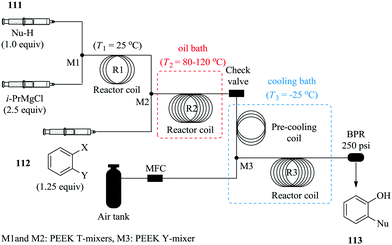
To further demonstrate the benefits of continuous flow processing in present literature with regard to process safety in multi-step syntheses;72,73 He et al. synthesized an array of functionalized phenols by aerobic oxidation of Grignard reagents in continuous flow reactors (Fig. 16).74 Their protocol was motivated by the promising results that they attained in continuous flow reactors where pure oxygen was used as the oxidant. The continuous flow reactors performed better than the batch reactors with shorter reaction times and better yields attained compared to the batch reactors (flow reactors: 53%, 2.7 minutes, 25 °C and batch reactors: 15%, 5 hours, 25 °C). The reaction was thereafter successfully done with pressurized air under cryogenic conditions with relatively good yields obtained when both electron-rich and deficient substrates were used. The authors took a step further and investigated the in situ generation and use of organo-magnesium intermediates in the synthesis of ortho-functionalized phenols. This was achieved by selective addition of magnesiated nucleophiles to a benzyne intermediate generated from 1,2-dihalobenzenes.
The three-step reaction took only 14 minutes to yield the desired ortho-functionalized phenols. Product yields ranging between 33% and 55% were obtained. This established continuous flow synthesis process enabled safe and easy tailoring of the organo-magnesium substrates and in turn a variety of functionalized phenols can easily be produced. Moreover, the isolation of the organo-magnesium intermediate is not required. This is yet another of many examples were unstable intermediates are skillfully handled in continuous flow systems.
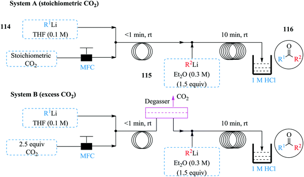
Wu et al. have also done some work involving the use of organolithium for the synthesis of ketones from carbon dioxide in continuous flow systems (Fig. 17).75 Two complimentary flow systems were developed for the synthesis i.e. System A and B in Fig. 17 above. System B was used in instances were excess CO2 was required. Both continuous flow protocols established were superior to the reported batch synthesis. The carboxylation was achieved in less than 1 minute whereas the formation of carboxylic lithium intermediate was completed in 10 minutes at room temperature, quenched with HCl to give desired ketones in high yields (40–92%). Notably, a lower amount of CO2 was needed in the continuous flow process compared to the batch process plus no alcohol by product obtained in the flow process. The established process conditions were extended to the use of Grignard reagents since some heteroatomic organolithium species blocked the system at room temperature. In addition, it was found that reactive secondary lithium compounds were prone to react with THF than with the carboxylic lithium salt intermediate or even CO2. As such, an additional process that facilitated the synthesis of ketones using CO2 and Grignard reagents was developed (Grignard/CO2/organolithium). The process equally boasts of short reaction times and good yields (41–75%). Furthermore, the synthesis of the organolithium substrates to the carboxylation step and formation of ketone was integrated with much success thus demonstrating how exothermic reactions such as these moreover involving gas–liquid flow, benefit from the large surface area to volume ratio of continuous flow systems that ensure fast mixing and efficient heat transfer rates.
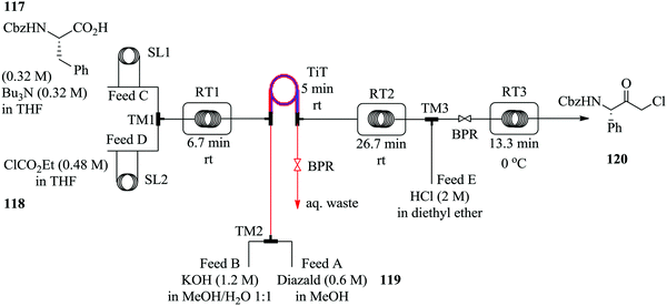
Diazomethane, a very important substrate in many a chemical transformation, is rarely exploited due to its very delicate nature; it is very volatile (boiling point −23 °C), toxic yet odourless and if subjected to abrupt change in temperature, is explosive. Moreover, due to its instability, diazomethane is preferably consumed as it is generated other than being stored therefore batch chemistries involving its use are notoriously dangerous and are performed with extreme caution. Continuous flow systems have recently been showed to enable the safe use of diazomethane in addition to other hazardous chemistries.76–81 For example, in the synthesis of α-halo ketones (Fig. 18) by Pinho et al., a commercially available tube in tube reactor was used to generate diazomethane.
A multi-step continuous flow process in the synthesis of α-chloro ketone 120 was developed. Cbz protected L-phenylalanine 117 was activated with ethyl chloroformate 118 in the presence of tributylamine at room temperature to form an anhydride in 6.7 minutes. The diazomethane formed from Diazald 119 in the tube in tube reactor, was thereafter immediately reacted with the anhydride for 31.7 minutes at room temperature to form the corresponding α-diazo ketone. This was then subjected to an ethereal solution of HCl in diethyl ether at 0 °C in turn yielding 87% of desired α-chloro ketone 120, a key intermediate for the synthesis of protease inhibitors.
Gas–liquid phase chemical reactions in batch reactors are known to suffer from insufficient mixing furthermore those involving the use of high pressure usually require the use of specialized equipment and safety protocols must be put in place. Continuous flow processing has been shown to overcome some of these challenges.82,83
The safe use of highly unstable intermediates in continuous flow processing is a given as illustrated in the above-mentioned examples however, are these intermediates fully consumed in their respective syntheses? Maurya et al., in their previous work involving the continuous in situ generation, separation and reaction of diazomethane84 found that only about 63% of the diazomethane generated could be separated and utilized for the subsequent reactions. In an attempt to improve their previous findings on the topic of in situ generation, separation and use of toxic and hazardous compounds in micro reactors, the in situ synthesis, separation and use of ethyl diazoacetate in droplet micro-reactor was explored as a model reaction.85
Ethyl diazoacetate was generated in situ from glycine ester 121 and concurrently separated from the reaction mixture using toluene as a solvent in a micro-droplet reactor (Scheme 24). With this approach, Maurya et al. were able to generate a yield of 99% ethyl diazoacetate in 2 minutes. The separated product 122 was then reacted with benzaldehyde 123 to form compound 124 in only 24 minutes. The micro-droplets formed in the first step of this organic synthesis enabled the efficient and rapid separation of ethyl diazoacetate and ultimately reducing the amount of toxic waste downstream of the continuous process. This is another good example of how micro-reactor technology not only enables safe handling of hazardous reagents and intermediates but also how it has been used to ensure a reduction of toxic waste produced. Various aldehydes were reacted with the generated ethyl diazoacetate to form 2-keto esters in high yields (62–81%). The generation and separation of the ethyl diazoacetate was very efficient (99% yield) that a negligible amount of waste was reported to have been produced.
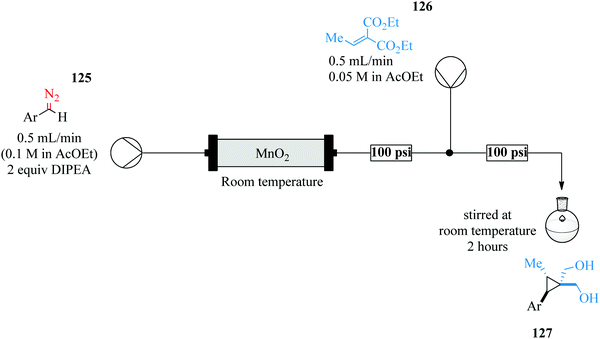
Continuous flow processing techniques have exhibited and enabled the discovery of new chemical reactive paths thus providing windows into untapped reaction possibilities in small reaction spaces86,87 Roda et al. successfully exploited the cyclopropanation of diazo species in continuous flow systems (Fig. 19).88
The room temperature cyclopropanation protocol gave high yields regardless of electron withdrawing (79–89%) or donating groups (89–99%) attached on the aryl ring of the diazo species. Furthermore, the yield was not affected by stearic hinderance due to ortho substituents. With such encouraging results, the diastereoselective cyclopropanation of a dipeptide was experimented in addition to the establishment of a telescoped sequence for the preparation of a cyclopropane amino acid. This gave an isolated yield of 85%.
Hafner et al. have demonstrated the use of continuous flow synthesis in the in situ generation and electrophilic quench of dichloromethyllithium, synthesis of dichlorocarbinols and benzyl pinacol esters which was achieved at −30 °C in a flow system (Fig. 20) followed by a semi-batch quench at room temperature.89
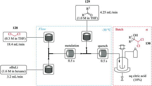 | ||
| Fig. 20 In situ generation and electrophilic quench of dichloromethyllithium in continuous flow reactors. | ||
It was reported that substrates with electrophilic substituents such as fluorine, bromine and nitro in the synthesis of dichlorocarbinols gave good yields (91–96%) in 1 s. With this continuous flow process, α-chloroboronic esters were also synthesised using a slight excess of dichloromethane in good yields (74–89%). A few aminothiazoles were also obtained in good yields (32–81%) by treatment of dichloromethylated alcohols with potassium hydroxide. The scientists were able to carry out chemistries in continuous flow in high yield and purity in only a second.
2.6 Reaction screening, optimization and automation
Over the years, there has been an accepted combination of continuous flow processing with statistical packages as well as automated software for reaction parameter screening.90,91 This combination augments the advantages of continuous flow processing. Through design of experiments and the process automation in continuous flow processing, the time required for reactor parameter screening and optimization is further shortened thus enabling rapid attainment of results, understanding of and rapid development of reaction processes. In comparison to batch reactors where automation of reaction procedures is not a given, the task of reaction parameter screening becomes difficult and time consuming.92 For example, the nucleophilic aromatic substitution of heterocycles with nitrogen nucleophiles93 in Fig. 21 was successfully optimized with the aid of design of experiments in a flow reactor.From the study, an optimum yield of 97% N-benzylquinazolin-2-amine 133 from the amination of 2-chloroquinazoline 131 with benzyl amine 132 was attained at a reaction temperature of 225 °C, 12 MPa pressure and residence time of only 16 minutes. The devised protocol was thereafter employed in the synthesis of a library of similar compounds from 2-chloroquinazoline with primary (yields: 73–90%) and secondary amines (yields: 64–79%) where it was proven to be robust. Low molecular weight amines like methylamine also gave product in good yield (73%). Electron rich and electron poor substituted anilines and heterocycles however, gave lower yields (27–63%). In spite of this, the optimized flow process can also be used as an alternative to microwave heating assisted amination of heterocycles with nitrogen nucleophiles since it enabled the use of high temperatures, a greener solvent and most importantly provided high reaction yields within a short time.
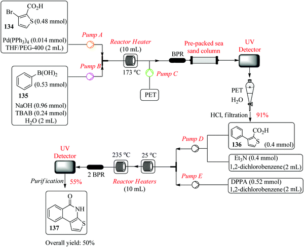
Filipponi et al., in their continuous flow synthesis of thieno[2,3-c]isoquinolin-5(4H)-one-A (TIQ-A), an important pharmacological tool and building block for PARP-1 inhibitors, used a set of central composite designs each comprising of a total of twelve experiments for the optimization of the Suzuki coupling reaction and cyclization step.94 The group successfully optimized the first step of the retrosynthesis; Suzuki coupling of 134 and 135 in the presence of palladium triphenylphosphine and TBAB phase transfer catalyst (Fig. 22). Two experimental points ((t: 146 °C, flow rate: 0.50 mL min−1) and (t: 173 °C and flow rate: 1.5 mL min−1)) were chosen and both gave a good degree of correlation between the predicted and the experimental yields. In addition, via investigative experiments, the optimum conditions required for the synthesis of acyl azide intermediate from 136 were also determined (t: 245 °C and flow rate: 0.1 or 0.2 mL min−1). The target compound 137 was obtained in 48% yield. This is a typical example that demonstrates how statistical design of experiments tremendously cuts down the amount of time required for reaction screening and optimization. The high temperature required for formation of 137, needed to be optimised since in the batch synthesis, this in addition to non-homogenous heating leads to by-product formation. It is also worth noting that on scale up of the process, 50% of 137 was achieved.
Alternatively, reaction optimization can be done in batch reactors with the aid of statistical experimental design after which the optimum parameters can then be translated into a continuous flow process. Either way, the reaction optimization is rapid with the use of such tools. Ferreri et al. successfully developed an optimized batch synthesis of 1,3-diiodo-5,5-dimethyl-imidazolidine-2,4-dione using a statistical experimental design and multi-linear regression (Scheme 25).95 From a total of eleven experiments, an optimized product yield of 55% was obtained at a stirring time corresponding to half the stirring time used in the experimental design experiments. On further investigation of the effect of the stirring time on the reaction, 15 minutes was found to be the optimum stirring time; a 67% yield was thereafter obtained.
The batch reaction was scaled up 10-fold and a yield of 67% in a total reaction time of 45 minutes was obtained. The optimized batch conditions were transferred to a multi-jet oscillating disk flow reactor (MJOD) where the reaction parameters were again screened to determine what would provide the best yield in this reactor platform. From the five experiments carried it, very low yield of desired product 139 was obtained. A semi continuous separation step was then incorporated into the continuous flow system. Buchner filter funnels were used to quickly remove the product from the reaction solution as a way of avoiding product losses and in turn increasing the reaction yield. In a reaction time of 9 minutes, 47 g h−1 of desired product was obtained from the MJOD. The product 139 was further used in the di-iodination of 1H-imidazole to produce 4,5-diiodoimidazole in 98% yield. Not only did the authors demonstrate the use of statistical experimental designs in screening of reaction parameters, they also showed how the use of a multi-jet oscillating disk reactor enabled the development of a continuous flow synthesis involving a solid as a product.
The reproducibility of research findings is also paramount in both academia research laboratories and chemical manufacturing industries. The coupled use of design of experiments and continuous flow synthesis facilitates the determination of error margins associated with a found result. This provides room for process parameter improvement at a lab bench scale and in turn increases confidence in process scale up going forward.91
The type of micro structured apparatus and equipment used for continuous flow processes in organic synthesis is also evolving. Organic chemists and chemical engineers have come together and joined forces to better utilise the vast as well as untapped opportunities that micro-reactor technology brings to chemical manufacturing. Examples include; a vortex fluidic device mediated room temperature esterification of di-acids.96 The vibrations native to the device are said to provide an improvement in the chemical reactivity through the Faraday waves generated and thus very short reaction times (3.25 minutes) and high yields (up to 90%) were observed. The importance of finely tuned flow rate in vortex fluidic device mediated continuous flow syntheses was also showcased.
Tilley et al. have developed an automated collection device for high-pressure continuous flow synthesis.97 The system includes sampling and collection functions with the capability to handle process interruptions and react accordingly. Using this device, a volume of material can successfully be guided to flow into a subsequent process line or made to exit the process environment based on the purity of the reactor output. To put the importance of coupling such technologies with flow processing into perspective, an example of batch product monitoring is made. In batch processing, contamination is usually discovered after the product has been collected moreover, on line and intelligent technologies that can help detect contaminants before product isolation and collection are difficult to incorporate into batch processing. On the other hand, flow processing can smoothly be coupled with such technologies, which can reduce the cost of processing of target compounds in the end. Similarly, using a non-invasive sensor, Antweiler et al. demonstrated how process parameters in multiphase slug flows can be rapidly monitored in micro-reactors without inflicting any disturbances to the flow structure.98
2.7 Integration of in-line analytics for real time analysis
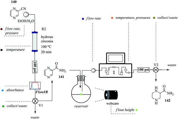
Continuous flow processing platforms permit the integration of micro-analytics into reaction processes and in so doing, they enable obtaining of vital information about a reaction's progress in real time ultimately shortening the time required for reaction screening.99–101 Notably, the use of micro-analytic tools with automated flow systems simplifies reaction processes. To demonstrate, Ingham et al. synthesized piperazine-2-carboxamide using an open-source software package and a Raspberry Pi® computer. These were employed in the machine-assisted multi-step flow preparation of pyrazine-2-carboxamide (Fig. 23).102 The heterogeneous catalytic hydration of pyrazine-2-carbonitrile 140 was achieved in only 20 minutes yielding 100% of pyrazine 141. The two reaction steps i.e. hydration and reduction were elegantly combined by employing a camera and reservoir containing a float. This way, sufficient amount of intermediate 141 to be used for the reduction reaction (H2, 10% Pd (C) at 100 °C) was ensured thus developing a semi-continuous process. A flow IR was used in this process as an analytic tool but was found to have a drawback when it came to identifying product 142 in the reduction step. Piperazine-2-carboxamide 142 and 1,4,5,6-tetrahydropyrazine-2-carboxamide have similar functionalities thus similar carbonyl stretching frequencies were obtained. NMR was used for this reaction step analysis. This semi-continuous protocol is useful for reaction steps that are not easy to telescope, require different flow rates and or include an easy separation or purification step such as solvent extraction.Using a self-optimizing flow reactor system, Holmes et al. were able to optimize a two-step telescoped synthesis of AZD9291, an irreversible epidermal growth factor receptor kinase inhibitor 145103 from aniline 143 and acid chloride 144 (Fig. 24). The protocol was adapted from their model synthesis of acrylamide derivative from 2,4-dimethoxyaniline.
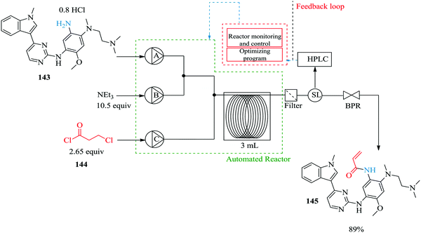 | ||
| Fig. 24 A two-step telescoped synthesis of AZD9291, an irreversible epidermal growth factor receptor kinase inhibitor. | ||
The model reaction: the synthesis of acrylamide from 2,4-dimethoxyaniline was extensively investigated in an automated flow reactor system with adaptive feedback control, reaction parameter monitoring and optimization algorithm; SNOBFIT algorithm and MATLAB interface were employed for this purpose. Using the algorithm and on line HPLC quantification with biphenyl as an internal standard, it was found that at a residence time of 12.2 minutes (flow rate: 0.1 mL min−1), reaction temperature of 118 °C, 16 eq. Et3N and 2 eq. of acid chloride 144, a 96% yield of acrylamide derivative was obtained. Compared to the batch synthesis (76% isolated yield at 0 °C in 3 hours), the flow synthesis performed well. The automated system also enabled the identification of impurities and the reaction conditions that favour their formation. With this kind of information, it becomes easier to push a reaction towards a desired product.
Archambault et al. recently demonstrated the use of a bench top NMR spectrometer for the rapid monitoring and optimization of four organic synthesis i.e. acid catalysed esterification, base-catalysed Knoevenagel condensation, Diels–Alder and alkylation reactions in continuous flow reactors.104 Reaction parameters such as temperature, concentration and stoichiometric ratios of reagents were investigated. By monitoring the signals of starting material and or desired product, conversions or yields were quickly generated in real time. It was also shown that the reactions had to be performed with high concentration of reagents for easy monitoring and assignment of peaks observed. Nonetheless, since continuous flow reactors are great tools for process intensification, this added advantage could be exploited in the scaled up syntheses.
For example, the base catalysed Knoevenagel condensation (Scheme 26) was carried using 2 M concentration of benzaldehyde 146 and ethyl acetoacetate 147 in the presence of 0.2 M piperidine 148 in ethyl acetate. The proton NMR signal of the unreacted benzaldehyde and that of the CH3 in the acetyl group of the alkene product were monitored. It was found that at a total reagent flow rate of 1 mL min−1, the conversion increased (26–63%) with increase in reaction temperature (from 45 °C to 85 °C). Additionally, the E and Z isomers of the product could be positively identified.
On-line analysis or monitoring of chemical syntheses is especially also very useful when it comes to reactions involving sensitive products such as Grignard reagents. The continuous flow synthesis of Grignard reagent, phenyl magnesium bromide (Scheme 27) has been efficiently followed using in line NMR spectrometer (Magritek spinsolve™).105 The synthesis was performed in a stainless steel tube (diameter: 1.1 cm, volume: 75 mL) equipped with a cooling jacket. Its outlet was connected to a flow cell (1.2 mL) using 1/8” Teflon tubing. NMR spectra were recorded every 10 to 15 seconds.
Using a syringe, commercial phenyl magnesium bromide was introduced into the magnesium powder (particle size: 250 μm) packed column for activation. The reactor was thereafter heated to 80 °C for 30 minutes. 100% conversion of benzyl bromide 150 to Grignard reagent 151 was obtained in 115 minutes. The authors also reacted the freshly formed phenyl magnesium bromide 151 with carbon dioxide and generated 152 in 70 minutes with an 80% conversion. From the in line analysis, the NMR spectra obtained showed that the oxidation of the Grignard reagent was not as significant as it was in the off line NMR analysis.
Attainment of kinetic data in continuous flow systems entails the analysis of reaction effluents at steady state conditions. This would require alteration of reaction conditions particularly the flow rate for any specific experiment to generate enough data to work with. In batch reactors, this is quite the opposite; a lot of data can be extracted from timed sampling performed on just one experiment. As such, there is a need for inline micro-analytics that will enable continuous variation of the reaction parameters, which in turn will lead to rapid generation of big kinetic data from just one experiment in flow.
Using a Paal–Knorr reaction (Scheme 28), Moore et al. demonstrated that the use of in-line IR and an automated micro-reactor system in the generation of time series data from the manipulation of flow rate can be rapidly achieved.106 Furthermore, the data generated is in agreement with results attained at steady state conditions.
The reaction between 2,5-hexanedione 153 and ethanolamine 154 in DMSO as a solvent to generate product 157 was used as a test reaction. A plot of the residence time profiles as a function of residence time gave the product concentrations at a given residence time profile. Conversion profiles at various reaction temperatures (50–170 °C) were also generated and the data was fitted in a kinetic model. K1 and K2 (Scheme 28) were calculated to be 12.2 ± 0.4 and 20 ± 0.9 kJ mol−1 respectively. Notably, the data in this study was generated in approximately 8 hours with only 5 mL of each 2 M reactant used. The authors also report that had traditional steady state reactions been performed for the study, the experiments would have taken almost 2 days, 13.5 mL of each reagent solution for the reaction and ultimately fewer data points would have been acquired.
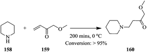
Braun et al. have recently developed a Raman system with increased signal intensities and fast acquisition of spectra. They illustrated the possibility of real time analysis in chemical synthesis involving hazardous reagents and products using a reduced laser power; 7 mW in the Michael addition of piperidine 158 to ethyl acrylate 159 (Scheme 29).107
The conversion of ethyl acrylate 159 was followed by monitoring the relative decrease in the difference in intensities at 1637 cm−1 and 1550 cm−1. Maximum conversion was achieved after 200 minutes. The results obtained were in good agreement with previously reported kinetic model of the reaction.108 Interestingly, the reaction was performed in a glass vial therefore, the reaction space might have assumed characteristics of a batch reactor nonetheless, the findings can be easily translated to the flow synthesis of 160. The authors additionally, looked into the Raman spectroscopic monitoring of a multi-phase slug flows. In the slug flow of toluene and water in a PFA capillary (1/16 in internal and 1/8 in external diameters), it was found that the frequency of droplet formation should be lower the measurement frequency. Raman spectra were collected in 60 ms with 50 ms integration time at a 5 Hz droplet formation frequency. The contents of both phases could easily be identified. When a PFA capillary of smaller internal (0.03 in) and external diameter (1/16 in) was used (droplet formation frequency of 24 Hz), the spectral measurement frequency could be increased to 333 Hz, which means that fast reaction processes with extremely fast sampling rates can also be effectively monitored using this developed analytical tool.
Using the Hoffman rearrangement, Bristow et al. demonstrate how on-line mass spectrometry, Microsaic 4000 MiD coupled to a FlowStat Evo B-400 flow reactor, in the continuous processing of an intermediate in an industrial chemical process under AstraZeneca's company profile, provides real time process understanding and optimization compared to off-line LC-MS analysis (Scheme 30). However, the off-line LC-MS was able to detect more impurities than the on-line MS.109
They also highlighted the importance of optimizing parameters such as dilution factor and ionization efficiency in on-line mass spectrometry analysis as they were shown to have a tremendous effect on the ions that were being monitored. The study addresses a common problem associated with on-line MS; sample concentration and reaction solvent compatibility to the instrument. A mass rate attenuator herein was used to transfer precise amount of sample from the flow reactor into a sampling make-up flow provided by a high-pressure Knauer pump and thereafter fed to the mass spectrometer. In this reaction, between a temperature range of 20 °C and 80 °C, the ideal sampling make-up flow composition was 50![[thin space (1/6-em)]](https://www.rsc.org/images/entities/char_2009.gif) :
:![[thin space (1/6-em)]](https://www.rsc.org/images/entities/char_2009.gif) 50 acetonitrile
50 acetonitrile![[thin space (1/6-em)]](https://www.rsc.org/images/entities/char_2009.gif) :
:![[thin space (1/6-em)]](https://www.rsc.org/images/entities/char_2009.gif) H2O + 0.1% formic acid. This provided the highest ion abundance of the amide 161 at 20 °C compared to 80
H2O + 0.1% formic acid. This provided the highest ion abundance of the amide 161 at 20 °C compared to 80![[thin space (1/6-em)]](https://www.rsc.org/images/entities/char_2009.gif) :
:![[thin space (1/6-em)]](https://www.rsc.org/images/entities/char_2009.gif) 20 H2O
20 H2O![[thin space (1/6-em)]](https://www.rsc.org/images/entities/char_2009.gif) :
:![[thin space (1/6-em)]](https://www.rsc.org/images/entities/char_2009.gif) acetonitrile + 0.1% formic acid and 50
acetonitrile + 0.1% formic acid and 50![[thin space (1/6-em)]](https://www.rsc.org/images/entities/char_2009.gif) :
:![[thin space (1/6-em)]](https://www.rsc.org/images/entities/char_2009.gif) 50 acetonitrile
50 acetonitrile![[thin space (1/6-em)]](https://www.rsc.org/images/entities/char_2009.gif) :
:![[thin space (1/6-em)]](https://www.rsc.org/images/entities/char_2009.gif) H2O + 0.05% TFA as sampling make-up flow compositions. With regard to the dilution factor, 3000
H2O + 0.05% TFA as sampling make-up flow compositions. With regard to the dilution factor, 3000![[thin space (1/6-em)]](https://www.rsc.org/images/entities/char_2009.gif) :
:![[thin space (1/6-em)]](https://www.rsc.org/images/entities/char_2009.gif) 1 was found to be the best. Additionally, it was seen that the isocyanate was not fully furnished in the process to form the corresponding amine. This was evident from the unchanging amount of isocyanate between reaction temperatures, 20 °C and 80 °C. The mass spectrometric data attained was also found to be reproducible with percentage relative standard deviation of ion abundancies for the amide (m/z 325), isocyanate (m/z 323) and amine (m/z 297) ranging between 8.7–10.9%.
1 was found to be the best. Additionally, it was seen that the isocyanate was not fully furnished in the process to form the corresponding amine. This was evident from the unchanging amount of isocyanate between reaction temperatures, 20 °C and 80 °C. The mass spectrometric data attained was also found to be reproducible with percentage relative standard deviation of ion abundancies for the amide (m/z 325), isocyanate (m/z 323) and amine (m/z 297) ranging between 8.7–10.9%.
Heiland et al. report monitoring stereo-selective transformations using integrated on-chip HPLC/MS analysis successfully.110 An ethylene diamine catalysed Knoevenagel condensation of aldehyde 165 and diketone 166 followed by an intramolecular hetero-Diels–Alder reaction of 167 to form 168 was carried out in a micro-chip flow reactor probed with an HPLC column coupled with mass spectrometry detection (Scheme 31). The authors found that the combination of HPLC and MS detection to the system enabled easy identification of diastereomeric products as opposed to just having a mass spectrometer directly coupled to the flow system.
At a flow rate of 10 μL min−1, residence time of 5.4 seconds, and reagent concentration of 0.1 mol L−1 citronellal, 0.12 mol L−1 Meldrum's acid and 10 mol% EDDA relative to the acid, excellent chromatographic baseline peak separation was attained. At higher catalyst loading, more product formation was observed. The system was excellent at these conditions however at very low flow rates, undesirable chromatographic analytical output such as peak broadening was observed. By re-designing the micro-chip periphery set up, effective separation of reactor fluid flow manipulations and the injection process that enabled a micro-batch operation combined with stopped flow was achieved (details of the re-design can be found in ref. 110). Additionally, this re-design was thereafter illustrated to be suitable for slower reactions such as the enantio-selective asymmetric iminium catalysed Friedel's Crafts alkylations. For such automated analytic tools to effectively monitor reactions and function as expected, a detailed investigation of the parameters that affect the identification and detections of compounds in the reaction mixtures fed to these instruments must be a prerequisite before any reaction monitoring is attempted.
2.8 High reaction throughput
In traditional synthesis apparatus, throughput of a chemical reaction is increased by increasing the size of the apparatus i.e. sizing up. On the other hand, continuous flow synthesis employs equalling up and numbering up techniques to effect high throughput.111–116 The former being defined as the increase of number of identical micro-structures and the latter as the parallel arrangement of multiple identical micro-structured equipment for continuous flow synthesis applications. The numbering up technique can be done internally or externally.117Wen et al. demonstrates equalling up technique in the continuous flow nitration of trifluoromethoxybenzene increased throughput.118 The continuous synthesis was achieved in a micro-reactor (length: 0.1 mm and ID: 6 mm) combined with a tubular packed reactor (packing material: quartz sand particles of average size 710 μm, porosity: 0.39) from which a selectivity of 90.7% to the para product 170 was observed (Scheme 32).
The synthesis was scaled up in a micro-reactor consisting of four plates with 16 channels per plate (1 mm × 0.5 mm × 85 mm, reactor volume: 2.72 mL). This was coupled with a distributed packed tubular reactor consisting of four tubular reactors (OD: 8 mm and ID: 6 mm). The reactors were packed with Φ2 × 2 cylindrical Quartz sand. 0.99 kg h−1 of desired product at a reaction selectivity of 98.1% was attained.
Deng et al. also demonstrates numbering up in the continuous flow synthesis of 2,4,5-trifluorobromobenzene using a self-made reactor system consisting of numbered up microchannels and 40 micromixers.119 The scientists synthesized the diazonium compound 175 in the self-made reactor system while the bromodediazoniation was carried out in a batch reactor to yield 2.73 kg h−1 of 176 in 40 minutes (Scheme 33). In comparison to the single micro-channel reactor synthesis, comparable throughput was reported.
Compared to sizing up, equalling and numbering up techniques are superior since the physical specifications of the synthesis apparatus or equipment remain unchanged in both protocols of increasing reaction throughput. As such, similar reaction output i.e. reaction conversions and yields are attained even on a larger scale. This is due to unaffected heat, mass and mixing efficiencies which is seldom the case with batch reactors which utilize sizing up technique.120 Zhao et al. demonstrates numbering up in the scale up of a luminescent solar concentrator-based photo-micro-reactor, where bifurcation/chamber and bifurcation/bifurcation micro-reactor structure designs consisting of various number of channels (8, 16 and 32) were developed.121 The [4+2] cycloaddition of 9,10-diphenylanthrancene with singlet oxygen generated via photosensitization in the presence of methylene blue was used for characterization of the reactors’ performance. Both reactor designs, proved greatly scalable. Furthermore, similar results to those observed with the use of a single channel reactor were observed (Scheme 34).
 | ||
| Scheme 34 [4+2] cycloaddition of 9,10-diphenylanthracene with singlet oxygen generated via photosensitization. | ||
It should be noted that sizing up can also be incorporated in scaling up of processes in continuous flow however; there are limitations to this technique. The physical aspects of the process equipment such as channel diameter and or length can only be increased to a certain point before the reaction throughput is compromised. For example, in the scaled up alkylation of benzoic acid by MeI in the presence of 1,8-diazabicyclo[5.4.0]-undec-7-ene (DBU)122 (Scheme 35), it was found that in the Corning low flow reactor (volume: 5.25 mL), at lower flow rates (<3 mL min−1), 20 °C and a residence time of 105 s, there was inefficient mixing. This was evident from the decrease in linearity of the reaction kinetic curve (slope = −2.23 × 10⁻⁴ mol L−1 s−1) observed however, at a flow rate of 3 mL min−1 20 °C and a residence time of 105 s, 85% conversion was attained. At 80 °C, the reaction productivity was improved to 6.82 g h−1. In contrast, using the low volume reactor (capillary microflow reactor: 13.2 μL) at 75 °C, 282 mg h−1 of product was obtained. This is a typical example of the limitations of sizing up in continuous flow synthesis especially when using commercially available equipment.122 Despite attaining similar kinetic rates in the batch and flow syntheses (0.020 and 0.021 L mol−1 s−1 respectively), the alkylation of benzoic acid in the Corning low flow reactor was demonstrated to be mixing controlled and any attempt to increase conversions by reducing the residence times in the low flow Corning reactor seemed futile.
 | ||
| Scheme 35 Scaled up alkylation of benzoic acid by MeI in the presence of 1,8-diazabicyclo[5.4.0]-undec-7-ene (DBU) in a Corning low flow reactor. | ||
3 The challenges faced in continuous flow processing
Although continuous flow processing has numerous benefits, it is also faced by some challenges that deter its widespread use in pharmaceutical, fine and specialty chemical processing; most especially at large scale production. These include difficulty in solid handling, integration of in-line purification techniques, changing the batch mind set in addition to the exorbitant cost of flow equipment and the lack of thereof for systematic scale up of processes. These issues are briefly expounded below with some examples of existing solutions provided.3.1 Solids as starting materials, products and or by-products
The biggest challenge facing the use of continuous flow processing in chemical synthesis is the formation of and use of solids.123,124 The channel diameters of continuous flow reactors; ranging from micrometer to millimetre, can barely handle the presence of solids in flow chemical syntheses. Innately, channel-fouling leading to eventual blockage is a common phenomenon and is a serious issue that causes major setback during reaction parameter screening stages. Referring to a pioneering study by Lonza, on the chemical reactions that can benefit from continuous flow processing,125 it was established that of the 86 chemical reactions in the company's profile, 50% of these reactions could possibly benefit from the continuous mode of chemical processing. 63% of this cluster of chemical reactions involves solids and would ultimately be problematic to carry out in micro-reactors using current technology.For reactions involving solid formation, the channel fouling and eventual blockage is usually attributed to the high concentration of reagents, which can only be circumvented effectively by using very dilute reactant solutions at a laboratory scale.126 Using flow reactors with bigger channel diameters is another option but could have detrimental effect on the mixing, heat and mass transfer efficiencies which in turn effect lower reaction throughput.127 Other feasible approaches involve micro-flow focussing technique to prevent deposition of solid material onto reactor channels,128 performing the reaction in a multiphase system129–131 and the use of ultrasound acoustic irradiation.132,133
Similarly, reactions involving solid materials being fed into micro-reactor systems in form of suspensions are also prone to clogging issues. To alleviate this problem, approaches such as addition of external forces like magnetic stirring in the feeding systems have been used.134 Notably, there are quite a few available devices that can be used for this purpose on a laboratory scale,135 however there use is costly as no two reaction feed suspensions containing particulates of different sizes; behave the same on exposure to an external magnetic field. As a result, in-house made systems become inevitable alternatives.
Continuous stirred tank reactors (CSTRs) are also being embraced as an option for chemical processing since they enable reactions that involve solids as products, reagents and by-products to be performed in a continuous manner.136 Mo et al. developed a cascade continuous stirred tank reactor system which was successfully used in two solid-forming chemical reactions i.e. the reaction of cyclohexylamine with glyoxal and the sulfonation of 2-octanol.137 The latter reaction involves a solid by-product while in the former; a solid product is generated. In both reactions, the ability of the cascade CSTRs to handle solid formation at relatively high solid loadings was tested.
The reaction of cyclohexylamine with glyoxal was done in a 6-unit CSTR cascade in series. At a solid loading of 4.4 wt%, 0.4 M glyoxal concentration, at a flow rate of 1 mL min−1 and stirring rate of 600 rpm, almost 100% conversion was achieved in 15 minutes. On the other hand, the sulfonation of 2-octanol in a 3 unit CSTR cascade in series gave full conversion at a flow rate of 1 mL min−1, 0.6 M 2-octanol and 0.72 M methanesulfonyl chloride what is more is that the system was run for 8 hours straight without clogging.
Savage et al. demonstrates with the synthesis of highly substituted sulphobutylether β-cyclodextrins how changing the mode of addition of reagents by using a continuous tank reactor (CTR) system remarkably improved the reaction output and provided products with desired characteristics compared to the batch synthesis.138 A hot solution of β-cyclodextrin in sodium hydroxide (60 °C), was fed into a CTR after which a solution of 1,4-butane sultone at the same temperature was added until less than 0.1 wt% of β-cyclodextrin was left in the reaction mixture. Notably, half the amount of sodium hydroxide used in the batch process was required in the CTR system. In addition, a 7![[thin space (1/6-em)]](https://www.rsc.org/images/entities/char_2009.gif) :
:![[thin space (1/6-em)]](https://www.rsc.org/images/entities/char_2009.gif) 1 molar ratio of β-cyclodextrin to 1,4-butane sultone was required as opposed to 10
1 molar ratio of β-cyclodextrin to 1,4-butane sultone was required as opposed to 10![[thin space (1/6-em)]](https://www.rsc.org/images/entities/char_2009.gif) :
:![[thin space (1/6-em)]](https://www.rsc.org/images/entities/char_2009.gif) 1 in the batch reactor system.
1 in the batch reactor system.
The authors hypothesized that the shielding of sodium hydroxide from the 1,4-butane sultone up to the point where it is actually needed for the reaction thus enabling efficient activation of the hydroxyl groups on the β-cyclodextrin, minimizes the degradation of 1,4-butane sultone to low molecular weight by-products. In fact, on investigation, it was found that an increase in mole ratio of sodium hydroxide to β-cyclodextrin indeed increased the average degree of substitution. The CTR system produced a higher average degree of substitution (an excess of 10) than what was observed in the batch system. Also the pH of the reaction was strictly controlled by only using about 10–20% molar excess of sodium hydroxide relative to the amount of 1,4-butane sultone used. This way, the formation of by-products was controlled therefore ensuring the presence of enough 1,4-butane sultone to effect the formation of desired highly substituted sulphobutylether β-cyclodextrin.
Heterogeneous catalysts, due to their easy recovery, high turnover frequencies, ability to improve reaction selectivity and yield are widely used in chemical syntheses.139 These are conveniently used in batch reactors however, with the benefits that continuous flow reactors have, the use of heterogeneous catalysis in flow processes is now prevalent. Heterogeneous catalysts are easily applied in continuous flow chemical syntheses with the use of packed column reactors,140 catalyst coated tubular reactors,141 monoliths etc.142–144
Battilocchio et al. skillfully demonstrates the benefit of continuous flow in the heterogeneous catalysed hydration of nitriles using manganese oxide (Fig. 25).145 This synthesis, previously performed in batch reactors at relatively high temperatures (>140 °C) and often marred with difficulty in separation of products as well as recovery of catalyst, was performed in a continuous flow reactor.
The authors were able to perform MnO2 catalysed hydration on a number of nitriles; α,β-unsaturated aliphatic, aromatic as well as heteroatom-substituted nitriles. Product yield ranging between 94–100% was achieved in a mild temperature range of 30–110 °C and residence time range of 2–60 minutes.
The synthesis of natural products has been explored in flow reactors. An example is Spirangien A. Newton et al. combined flow and batch protocols in its synthesis.146 They began with the flow synthesis 185 from a Wittig reaction involving 2,3-butane diacetal protected aldehyde 184 to yield α,β-unsaturated methyl ester 185 using a triphenylphosphine oxide catalyst. The methyl ester was thereafter subjected to an asymmetric hydrogenation where Pflatz’catalyst was employed in a tube in tube reactor to form vicinal diol 186. This was followed by a protecting group switch on the vicinal diol 186 to generate acetonide 187 which was converted into homoallylic alcohol 189via reduction–crotylation route (Scheme 36). Thus far, flow synthesis was reported to greatly benefit the generation of the above intermediates in the above reaction steps. To elaborate; (i) the reaction steps were easily telescoped. (ii) Due to the excellent temperature control in flow systems, methyl ester 185 was said to have been selectively reduced reproducibly to aldehyde 184. (iii) The tube in tube reactor enabled safe hydrogenation which required pressurized gases in addition to the use of small volumes of the gases.
3.2 Integration of in-line purification techniques
Despite the fact that continuous flow systems reduce the time required for down-stream unit operations, why use continuous flow systems for chemical synthesis yet the work up procedures to attain desired compounds from reaction mixtures are done using batch equipment? This is still a hot topic of discussion in many circles and as such has driven researchers to develop and investigate the viability of in-line purification techniques such as liquid–liquid extraction,147–149 micro-distillation,150 micro-crystallization151 and free-flow electrophoresis152 in addition to integrating work up procedures in continuous flow processes.153 This integration, although still difficult and includes thinking outside the box, has the potential to optimize product recovery by reducing the loss of product recovered in sequential work up steps due to poor handling. This is embodied in the reaction processes below. Using the Doebner–Miller synthesis of quinaldines, Yadav et al. displayed the benefit of using a continuous flow process as opposed to the batch process in this regard.154Since the synthesis of quinaldines involves the polymerization of crotonaldehyde 191 (Scheme 37) that forms a sticky mass, continuous stirred tank reactors (CSTR) were a good choice of process equipment. Notably, they were also employed in the work up procedures. Four CSTRs in series were used to complete the synthesis and work procedures.
Aromatic substituted anilines (nitro, methoxy and methyl groups) were reacted with acidified (50% H2SO4) crotonaldehyde 191 at 95 °C in two CSTRs where the reaction mixture was maintained for 45 minutes in each CSTR. After which it was fed into the third and fourth CSTR for work up. The work up procedure took only 60 minutes from which quinaldine derivatives 192 were obtained. Compared to the batch procedure where a total residence time of 200 minutes is needed, the CSTRs synthesis and work up protocol was less time consuming. Additionally, better selectivity was observed in the CSTR synthesis than in the batch synthesis of quinaldines. Even though the batch reactor is able to provide complete conversion over a prolonged period, the CSTRs in series also gave conversions between 92–96% depending on aniline substrate.
Similarly, Dai et al. illustrate how flow chemistry is evolving by incorporating work-up procedures usually carried out in a batch manner onto continuous flow processes. Atropine, an API having both anti-cholinergic and anti-parasympathetic properties was cleverly attained in >98% purity from a three-separator strategy. By-products (Scheme 38), which were structurally similar to the desired product, were fully removed using an easy liquid–liquid separation technique and careful pH control.155 A pH based continuous in line separation using membrane based separators was employed to give product 195 with 98% purity in 7.7% overall yield (Fig. 26).
From an industrial perspective, time is always money. The less time required to generate a desired product, the more sales and revenue generated. The synthesis of chloride derivatives in batch reactors using HCl is a bit complicated. The reaction is slow and only very mild reaction temperatures can be tolerated lest the solubility of hydrogen chloride in the reaction media is compromised. Briefly, any attempt to increase reaction temperatures with the aim of increasing the rate of reaction is detrimental to the reaction output.
On the contrary, micro-flow systems enable the use of reaction solvents above their boiling points since these systems can be pressurized. Borukhova et al. successfully synthesized chloride derivatives that were subsequently used in a nucleophilic reaction in the synthesis of important active pharmaceutical ingredients in micro flow capillary reactors (Scheme 39).156 For example, the two-step continuous flow synthesis of cyclizine 204 took a total residence time of 55 minutes within which a yield of 94% was achieved. It is also noteworthy that the first step of this synthesis; the generation of the chloride derivative 202 from diphenyl methanol 201, took only 10 minutes and was performed at a high reaction temperature of 100 °C. Furthermore, an in line liquid–liquid separator which enabled the convenient combination of the first reaction step product, chlorodiphenylmethane 202 without further purification, to 203N-methyl piperazine to generate the desired compound, cyclizine 204 was employed.
A MiniPharm continuous purification system has been used in the continuous flow synthesis of diphenhydramine 207, an anti-histamine administered orally in form of its hydrochloride salt (Scheme 40).157 The reaction was preliminarily monitored and optimized by on-line MS where air segmented flow was utilised to minimise the amount of product wasted during acquisition of MS data.
It was found that at 200 °C, a conversion of 66.1% was recorded at a reaction time of 5 minutes. An air segmented flow crystallizer module was thereafter integrated into the flow system. The MiniPharm consisted of a T-junction, which had fluid lines from the micro reactor outlet and a syringe pump containing ethyl acetate connected to it. In order to circumvent immediate solid formation in the PFA tubing pre-MiniPharm, the authors used home-made cut to length tube heaters to prevent premature solid formation in the flow system that in turn would cause blockages. A second T-junction was used to combine the heated fluid stream containing ethyl acetate and micro-reactor effluent with a stream of nitrogen gas. The resultant segmented nitrogen flow was passed through dry ice to facilitate crystallization of the product. The authors also explored a telescoped two step continuous flow synthesis of diphenhydramine 207 from benzhydrol, where the highest conversion attained at reaction temperatures: 150 and 200 °C, residence times: 2.5 and 0.33 minutes using acetonitrile as a reaction solvent for both steps respectively was 54.9%.
Free flow electrophoresis has also been demonstrated to be a feasible purification technique, which can easily be integrated into continuous flow synthesis processes152,158 however, this also is faced with a major challenge; the lack of an efficient “one size fits all” detection technique. As such, the pairing of different detection techniques is common. Examples of some detection techniques include mass spectrometry,159,160 and fluorescence imaging.161–163 As has been demonstrated in the above-mentioned examples, the integration of in-line purification techniques is possible but is still quite a challenge.
3.3 Changing the batch mind set
Although the United States Food and Drug Administration as well as the European Medicines Agency have recently shown support for the use of continuous flow chemistry in a synthesis,164,165 the pharmaceutical, fine and specialty chemical industries have their roots buried deep in batch processing as a mode of chemical production. It takes a lot of convincing for this sector to adapt continuous flow processes however, since the chemical manufacturing industry's image is tainted with production of large amounts of toxic, hazardous wastes, a technique that would help restore its image and provide tangible evidence as to how it would make this happen, would be very much welcomed. Life cycle assessment studies comparing batch and flow processes are an approach that can be used to persuade these players to come to the party. These studies encompass the environmental and economic benefits of the technology or mode of processing concisely providing a clear picture of what is to be expected.166–168 To illustrate, a batch, mini and pilot plants for a Buchwald–Hartwig amination reaction (Scheme 41) were each subjected to a life cycle assessment study.169A process comparison showed that the batch process scored high on most impact categories as compared to the flow process involving recycling of catalyst. In the instances where toluene recycling was incorporated in the processes, the flow process scored low compared to the batch process. High scores on the human toxicity potential (HTP) and ozone depletion potential (ODP) were higher than those attained in the batch process. It was also found that recycling toluene and all solvents used in the preparation of the catalyst (Pd–NHC) in the flow process seemed to be the best protocol as considerably lower scores were recorded. This shows the great impact solvent use has on the indicators.
The contribution of the reagents and starting materials to the selected indicators for the amination reaction was also assessed. For example, toluene production in the flow process contributes 58% and 38% to cumulative energy demand (CED) and climate change (GWP) respectively. In general, the impact of catalyst production in both processes was found to be significant; in the flow process, it contributes 12% to CED, 31% to GWP and 74% to HTP while in the batch process, 14%, 30% and 86% respectively.
In this study, it was shown how continuous flow processing could be used to alleviate the effect of chemical processing on the environment. From the findings of the life assessment of catalyst production, it is seen that in the production of [Pd(IPr)(cin)Cl], the catalyst used in the flow process had higher scores on all selected categories compared to the production of the batch process catalyst, [Pd(OAc)2/BINAP].
This was due to the large amounts of solvents; tetrahydrofuran and dichloromethane that was used in the production process however the use of N-methylpiperazine was seen to influence scores in both the batch (33% CED, 28% GWP and 86% terrestrial acidification potential (TAP)) and flow (28% CED, 29% GWP and 90% TAP) amination reactions. The influence of this reagent negates the negative results found in the catalyst production assessment and as such, it eventually influenced the outcome of the assessment of the flow Buchwald–Hartwig amination reaction.
A life cycle assessment on the multi-step synthesis of rufinamide by Ott et al. nicely compared the life cycle assessment and green metrics of existing batch and flow synthesis of the compound.170 It also highlighted the aspects of the batch synthesis that had potential for improvement i.e. by looking at various processing scenarios. These include; (i) connecting two batch reactors-two pot batch–batch. (ii) Two pot conti-batch where the cycloaddition was translated into a flow process. (iii) Telescoping both reactions in batch and lastly (iv) implementing reactant, product and solvent recovery (one pot recycled), it was found that the two pot batch–batch scored highly on all the life cycle impact assessment categories whereas the one pot batch recycled processing scenario scored the lowest among the four processing scenarios investigated. This therefore motivated the researchers to develop a completely continuous micro-reactor process that telescoped, connected all reaction steps and included solvent recycling. The synthetic route chosen by the authors involved the use of 2,6-difluorobenzyl alcohol 212 as a precursor for the synthesis of 2,6-difluorobenzyl azide 214 (Scheme 42).
HCl was used in place of highly toxic thionyl chloride to afford 2,6-difluorobenzyl chloride 213. In search for the best dipolarophile; methyl propiolate, propiolic acid, (E)-methyl-3-methoxyacylate or 2-chloroacrylonitrile in the batch routes, (E)-methyl-3-methoxyacrylate (EMMA) 215 was ranked number one due to the solvent-less click reaction and environmentally friendlier methanol used in the work up compared to ethyl acetate and ethyl ether used in methyl propiolate and propiolic acid respectively. The NFPA hazard ratings of EMMA (2;2;0) were also quite low as compared to the other dipolarophile options moreover EMMA is cheap (cost $2 per mol) however, based on the CED median value of EMMA (94 MJ kg−1), it cannot be considered a green dipolarophile. This highlights the complexity in assignment of the ecological backpack.
The dipolarophile contribution to the Global warming potential indicator (GWP), shows that EMMA has the least impact therefore confirming that it is the best dipolarophile of the four options investigated. To summarise, EMMA was found to be low on costs and hazard, lower product mass index with and without water (19 ± 3 and 18 ± 2 kg kg−1) and solvent rates (14 ± 2 kg kg−1). Consequently, this dipolarophile was used for the further optimization of 1,3 cycloaddition.
2,6-Difluorobenzyl azide 214 was also found to significantly contribute to the environmental impact of the dipolarophiles in turn affecting choice of the dipolarophile. To summarise, switching from multi-step batch to multi-step flow and simultaneously integrating solvent recycling strategies significantly reduced all the life cycle assessment impact potentials by 45% on average. Furthermore, a multiple and single injection point mode of processing was investigated. The results predicted that a combination of single injection processing with methanol recycling would reduce all impact categories by 33% on average.
Aside from the extensive life cycle impact assessments studies on chemical processes, comparison of existing real world batch chemical manufacturing process steps with their proposed continuous flow processes and scale up studies is also very important. The successful scale up of a key asymmetric hydrogenation step in the synthesis of an API has been demonstrated using continuous flow solid supported catalysis (Scheme 43).171
The Augustine approach was elegantly used here to anchor the molecular catalyst onto phospho tungstic acid and aluminium oxide support. THF was used as a solvent for the hydrogenation of 218 to generate 219 at a reaction temperature of 22 °C. At a substrate concentration of 0.6 M, reactor and catalyst bed volume of 8 and 3.8 mL respectively, a turn over number of 5000 in the first 7 hours with almost full conversion in addition to a 98% ee was achieved. A space-time yield of 520 g L−1 h−1 and less than 1 ppm of Rh in the product stream was observed. Similar observations were made when reactor and catalyst bed volume of 6.0 and 2.7 mL respectively hence proving the potential of scalability of the reaction step.
The reaction step was thereafter scaled up to a 1 kg per day scale where on line analysis was integrated into the continuous process. At similar reaction conditions in a reactor volume of 150 mL, an initial conversion of 99.6% and an enantiomeric excess ranging between 98.9% and 98.6% surpassing the cut off value of 98% ee throughout the process was seen. Despite the few glitches experienced such as replacing the syringe pump with an HPLC pump and malfunctioning of the hydrogen gas mas flow controller, 10-fold increase in space-time yield was recorded. The batch hydrogenation of 218 (660 mL reactor volume), in a reaction time of 32 hours and an estimated process time of 64 hours, a space time yield of 47 g L−1 h−1 and 260 ppm Rh in crude product was recorded. Furthermore, the amount of catalyst required for the reaction (10.1 mmol) was higher than that in the continuous flow synthesis (0.68 mmol).
Translation of a multi-step batch process into a multi-step continuous flow process is faced with challenges such as solvent compatibility, in flow purification/separation of by products and control over feed concentrations at each reaction step. These need to be accurately ironed out before the process is transformed into a continuous one. Aponte-Guzman et al. illustrates this in the bicatalytic continuous flow cyclopropanation-homo-Nazarov type cyclization (Scheme 44).
The cyclopropanation of diazo 220 and subsequent ring opening cyclization reaction were initially independently optimized in batch reactors. Acetonitrile was found to be a suitable solvent for both reaction steps (cyclopropanation at 0.2 M in CH3CN; 1 mol% Rh2esp2, 15 min, 50 °C and 89% yield, ring opening cyclization at 0.1 M in CH3CN; 5 mol% In(OTf)3, 15 min, 50 °C and >99% yield). Both reaction steps were thereafter independently performed in a continuous manner (cyclopropanation at 0.2 M in CH3CN; 0.001 M Rh2esp2, 30 min, 50 °C and >97% conversion, 81% average yield of diastereomers, ring opening cyclization at 0.1 M in CH3CN; 0.005 M In(OTf)3, 30 min, 50 °C and 99% yield). The two optimized continuous flow reaction steps were thus effortlessly combined into one continuous flow process. After 50 minutes of reaction time, 96% yield was obtained from cyclopropanation of 220 (0.001 M Rh2esp2 in CH3CN 0.1 M, 50 °C) and ring opening cyclization of the cyclopropane (0.005 M In(OTf)3 in CH3CN 0.2 M, 50 °C). A throughput of 4.7 g h−1 was achieved. In comparison with the combined batch processes of the reaction steps (1 mol% Rh2esp2, 5 mol% In(OTf)3, 30 min, 88% yield) better reaction yields were observed from the flow processes.
Ogasawara et al. have successfully synthesised (−)-oseltamativir in a multi-step single passage continuous flow process (Fig. 27). The synthesis was first fully optimized in batch and thereafter translated into its continuous flow process.33 All reagents but the zinc catalyst required for the reduction of nitro group to amine, were delivered into the flow system as liquids. The multi-step continuous synthesis consisted of five flow units, which were smoothly connected, in series. There was no isolation of intermediates between the flow units. A total residence time of 310 minutes was recorded for the total synthesis of (−)-oseltamativir. At a concentration of 0.04 M of nitroalkane 222 a flow rate of 0.04 mL min−1 and a reaction tube of 0.96 mm bore size for four flow units except for the fifth unit (consisted of a reactor column packed with zinc and celite), a throughput of 58 mg per 15 hours was achieved. Compared to their previously reported batch synthesis, the yields obtained were comparable.
Despite the numerous benefits that continuous flow processing brings to chemical syntheses, not all syntheses can be elegantly carried out in continuous flow systems. An integrated batch and flow approach to such syntheses could be a solution.172,173 Ley et al. recently integrated batch and flow systems in the synthesis of 5-methyl-4-propylthiophene-2-carboxylic acid 230, a precursor for anti-cancer drug candidate AZ82 (Scheme 45).174 In this synthesis, batch unit operations such as solvent extraction and distillation were incorporated into the synthesis platform. Traditional batch apparatus (round bottomed flasks) was modified to enable smooth integration of the two modes of synthesis. The automated cloud-based system enabled easy reaction monitoring and detection of any mishaps in real time. The otherwise tedious, time consuming and irreproducible addition of reagents in ordinary batch syntheses was also eliminated. The desired carboxylic acid 230 was attained in a 30% yield, a 3% increase compared to that achieved from its complete batch synthesis.
 | ||
| Scheme 45 Continuous flow synthesis of 5-methyl-4-propylthiophene-2-carboxylic acid, a precursor for anti-cancer drug candidate AZ82. | ||
Carmona-Vargas et al. demonstrate some advantages of combining batch and continuous flow setups in the synthesis of curcumin 235 and two of its analogues (Scheme 46).175 Synthesis step 1, which involves slurry formation, was firstly optimized in a batch reactor (10 mmol acetylacetone 231, 5 mmol B2O3, and 40 mmol B(O-n-Bu)3 heated at 70 °C for 30 minutes to form complex 232 after which vanillin (35.2 mmol) 233 was added to complete the first reaction step using a batch approach.
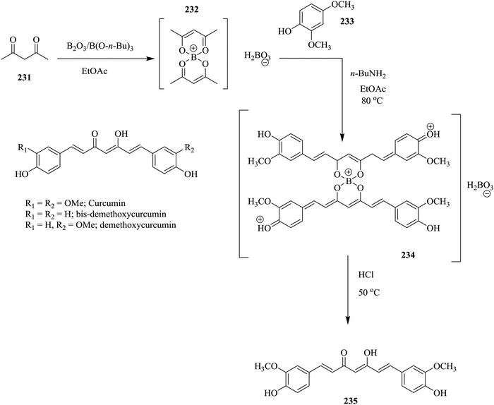 | ||
| Scheme 46 Combining batch and continuous flow setups in the synthesis of curcumin and two of its analogues. | ||
The second step was thereafter carried out using flow equipment; a heated tubular reactor (40 mL, 80 °C) and a double channel Syrris® syringe pump to deliver n-BuNH2 (0.6 eq.) and step 1 mix of vanillin 233 (7.05 eq.) and complex 232 (5 mmol) via a T-piece at a flow rate of 0.3 mL min−1 per reagent stream. The last step, boron decomplexation was carried out in batch with HCl (1 mol L−1) at 50 °C. Pure product 235 was obtained after extraction and crystallization from ethanol![[thin space (1/6-em)]](https://www.rsc.org/images/entities/char_2009.gif) :
:![[thin space (1/6-em)]](https://www.rsc.org/images/entities/char_2009.gif) water (1
water (1![[thin space (1/6-em)]](https://www.rsc.org/images/entities/char_2009.gif) :
:![[thin space (1/6-em)]](https://www.rsc.org/images/entities/char_2009.gif) 1). 60% yield; 24.1 g of product was generated per day after scale up of this synthesis approach. The full continuous flow approach of this synthesis comprised of a suspension of acetylacetone (10 mmol) 231, B2O3 (5 mmol) and B(O-n-Bu)3 (40 mmol) being fed into a loop module (40 mL) connected to a heated tubular PTFE reactor (10.5 mL, 80 °C). The formed complex 231 was thereafter mixed with a 0.075 mol L−1 solution of 3 eq. n-BuNH2 flowing at 0.3 mL min−1. HCl (1 mol L−1) was delivered at a flow rate of 0.9 mL min−1 into a collection flask containing complex maintained at 50 °C. This approach generated only 51% yield; 20.5 g of product per day. The drop in throughput was attributed to the suspension/slurry formed in the first step. The shaker, fitted onto the loop module used in the continuous flow integration of the first reaction step, was speculated not to be effective in mixing the slurry.
1). 60% yield; 24.1 g of product was generated per day after scale up of this synthesis approach. The full continuous flow approach of this synthesis comprised of a suspension of acetylacetone (10 mmol) 231, B2O3 (5 mmol) and B(O-n-Bu)3 (40 mmol) being fed into a loop module (40 mL) connected to a heated tubular PTFE reactor (10.5 mL, 80 °C). The formed complex 231 was thereafter mixed with a 0.075 mol L−1 solution of 3 eq. n-BuNH2 flowing at 0.3 mL min−1. HCl (1 mol L−1) was delivered at a flow rate of 0.9 mL min−1 into a collection flask containing complex maintained at 50 °C. This approach generated only 51% yield; 20.5 g of product per day. The drop in throughput was attributed to the suspension/slurry formed in the first step. The shaker, fitted onto the loop module used in the continuous flow integration of the first reaction step, was speculated not to be effective in mixing the slurry.
A complete batch synthesis of Curcumin 235 from acetylacetone (10 mmol), n-BuNH2 (0.6 eq.) and vanillin (7.05 eq.) gave a yield of a 69% and 12 g per day. It took 4.5 hours (work-up operation times not included) to finish the three reaction steps whereas the batch and continuous flow synthesis took 66.6 minutes. It should be noted that the two analogues synthesised; bis demethoxycurcumin (batch and continuous flow; 60% yield, 20.6 g per day. Continuous flow; 45% yield, 15 g per day) and demethoxycurcumin (batch and continuous flow; 30% yield, 6.2 g per day. Continuous flow; 15% yield, 3.1 g per day), also showed that the combination of batch and flow synthesis approach provided better throughput.
3.4 The cost and availability of flow equipment
Lastly but not least, at the end of the day, money talks. With the exorbitant prices of commercially available flow equipment, the development of world-class flow chemistry laboratories at a research level as well industrial level is only but a dream to many. As a result, this has encouraged groups to engineer their own bespoke homemade flow equipment and set ups to meet their needs. This is evident in the available literature.176–178 Despite the fact that continuous flow synthesis enables high throughput via scaling up strategies, there are issues that still need to be addressed. For instance, equal distribution of flow is crucial in numbered up and or equalled up reactors with blockages being the main cause of non-uniform flow distribution and mixing inefficiencies. As a result, the reactor assembly throughput is affected. Kuijpers et al. demonstrate the effect of blockages in a numbered up photo-micro-reactor assembly179 used in the dimerization of thiophenol to diphenyl disulfide.Simulating double and single channel blockages on the system, showed larger variation in throughput for double channel (standard deviation >25%) than in a single channel blockage (standard deviation approximately 15%). The average reaction yield was also observed to decrease with an increase in the number of blocked channels. This was due to the increased flow rate in the non-blocked channel that led to shorter residence times. Gratifyingly, the developed reactor did not suffer from flow maldistribution under variable power of light however, a significant drop in yield was observed in the first reactor. The availability of flow equipment especially for scaling up reactions is still lacking. It is however interesting to note that in 2016, the global flow chemistry market size was reported to be USD 1023.7 million and growing at a compound annual growth rate of 9.9%.
4 Concluding remarks
Continuous flow chemistry, as demonstrated in this review, offers numerous advantages to organic synthesis such as assured safety, environmentally benign processing, shorter reaction times, excellent yields and selectivity, reduced amount of by-products, use of elevated reaction conditions, easy reaction control, optimization and scale up etc. Additionally, as can be seen from the examples given herein illustrating the translation of batch chemistries into continuous flow processes, it is clear that despite the fact that flow processes provide a number of advantages to these chemistries; their translation is not an easy task. There are still some challenges encountered due to insoluble starting materials, switch of reaction solvent when incompatibility issues are foreseen in multi-step syntheses, formation of insoluble products and or by-products either in the middle or at the end of a synthetic route and work-up operations (such as filtration, extraction and purification). These are just a few of the challenges therefore, the important question here is, must all batch chemistries be translated to fully continuous flow processes or must we create a union between batch and flow systems to overcome these challenges to better benefit from flow synthesis processing?Nevertheless, some industries have already been reported to have adopted this mode of processing180 with a number of continuous flow synthesis processes developed and patented.181–184 In light of this, the possibility of further adopting this mode of processing for appropriate chemical production, especially in the form of micro-reactor technology is high. It however should be incessantly stressed that it will not completely replace conventional batch processing. Alternatively, a combination of conventional continuous processing with micro-reactor technology; micro-conti processing, has been identified to be promising.185,186
Conflicts of interest
There are no conflicts to declare.Acknowledgements
We wish to thank the National Research Fund (NRF grant 85103) and Nelson Mandela University for their financial support.References
- M. Balti, M. L. Efrit and N. E. Leadbeater, Tetrahedron Lett., 2016, 57, 1804–1806 CrossRef CAS
.
- X. Hu, N. Zhu, Z. Fang, Z. Li and K. Guo, Eur. Polym. J., 2016, 80, 177–185 CrossRef CAS
.
- B. Wenn, M. Conradi, A. D. Carreiras, D. M. Haddleton and T. Junkers, Polym. Chem., 2014, 5, 3053–3060 RSC
.
- S. Inuki, K. Sato, T. Fukuyama, I. Ryu and Y. Fujimoto, J. Org. Chem., 2016, 82, 1248–1253 CrossRef PubMed
.
- M. O. Frederick, J. R. Calvin, R. F. Cope, M. E. Letourneau, K. T. Lorenz, M. D. Johnson, T. D. Maloney, Y. J. Pu, R. D. Miller and L. E. Cziesla, Org. Process Res. Dev., 2015, 19, 1411–1417 CrossRef CAS
.
- J. Britton and T. F. Jamison, Angew. Chem., Int. Ed., 2017, 56, 8823–8827 CrossRef CAS PubMed
.
- J. Schachtner, P. Bayer and A. J. Von Wangelin, Beilstein J. Org. Chem., 2016, 12, 1798–1811 CrossRef CAS PubMed
.
- T. H. Rehm, S. Gros, P. Löb and A. Renken, React. Chem. Eng., 2016, 1, 636–648 RSC
.
- M. Baumann and I. R. Baxendale, React. Chem. Eng., 2016, 1, 147–150 RSC
.
- D. Rackl, P. Kreitmeier and O. Reiser, Green Chem., 2015, 18, 214–219 RSC
.
- J. H. Bannock, W. Xu, T. Baïssas, M. Heeney and J. C. de Mello, Eur. Polym. J., 2016, 80, 240–246 CrossRef CAS
.
- L. H. Andrade, W. Kroutil and T. F. Jamison, Org. Lett., 2014, 16, 6092–6095 CrossRef CAS PubMed
.
- M. Planchestainer, M. L. Contente, J. Cassidy, F. Molinari, L. Tamborini and F. Paradisi, Green Chem., 2017, 53, 3007–3048 Search PubMed
.
- E. Kilcher, S. Freymond, E. Vanoli, R. Marti, G. Schmidt and S. Abele, Org. Process Res. Dev., 2016, 20, 432–439 CrossRef CAS
.
- P. Rullière, P. Cyr and A. B. Charette, Org. Lett., 2016, 18, 1988–1991 CrossRef PubMed
.
- T.-L. Cheung, L. Hong, N. Rao, C. Yang, L. Wang, W. J. Lai, P. H. J. Chong, W.-C. Law and K.-T. Yong, Nanoscale, 2016, 8, 6609–6622 RSC
.
- A. Larrea, V. Sebastian, A. Ibarra, M. Arruebo and J. Santamaria, Chem. Mater., 2015, 27, 4254–4260 CrossRef CAS PubMed
.
- A. Polyzoidis, T. Altenburg, M. Schwarzer, S. Loebbecke and S. Kaskel, Chem. Eng. J., 2016, 283, 971–977 CrossRef CAS
.
- M. Jiao, J. Zeng, L. Jing, C. Liu and M. Gao, Chem. Mater., 2015, 27, 1299–1305 CrossRef CAS
.
- S. E. Skrabalak and R. L. Brutchey, Chem. Mater., 2016, 28, 1003–1005 CrossRef CAS
.
- M. Thiele, J. Zi En Soh, A. Knauer, D. Malsch, O. Stranik, R. Müller, A. Csáki, T. Henkel, J. M. Köhler and W. Fritzsche, Chem. Eng. J., 2016, 288, 432–440 CrossRef CAS
.
- M. Wojnicki, M. Luty-błocho, V. Hessel, E. Csapó, D. Ungor and K. Fitzner, Micromachines, 2018, 9, 248 CrossRef PubMed
.
- M. Thiele, A. Knauer, D. Malsch, A. Csáki, T. Henkel, J. M. Köhler and W. Fritzsche, Lab Chip, 2017, I7, 1487–1495 RSC
.
- N. J. W. Straathof, B. J. P. Tegelbeckers, V. Hessel, X. Wang and T. Noël, Chem. Sci., 2014, 5, 4768–4773 RSC
.
- M. Chen and S. L. Buchwald, Angew. Chem., Int. Ed., 2013, 52, 1–5 CrossRef
.
- Z. Xiaodan, H. Ping, L. Yaming and C. Duan, Org. Biomol. Chem., 2015, 13, 10917–10922 RSC
.
- G. A. Price, A. R. Bogdan, A. L. Aguirre, T. Iwai, S. W. Djuric and M. G. Organ, Catal. Sci. Technol., 2016, 6, 4733–4742 RSC
.
- N. Palaychuk, T. J. Delano, M. J. Boyd, J. Green and U. K. Bandarage, Org. Lett., 2016, 18, 6180–6183 CrossRef CAS PubMed
.
- T. P. Petersen, M. R. Becker and P. Knochel, Angew. Chem., Int. Ed., 2014, 53, 7933–7937 CrossRef CAS PubMed
.
- S. Calderwood, T. L. Collier, V. Gouverneur, S. H. Liang and N. Vasdev, J. Fluorine Chem., 2015, 178, 249–253 CrossRef CAS PubMed
.
- L.-H. Du, B.-Z. Cheng, W.-J. Yang, L.-L. Xu and X.-P. Luo, RSC Adv., 2016, 6, 59100–59103 RSC
.
- M. Kitchin, K. Konstas, M. L. Czyz, P. Valente, C. J. Sumby, M. R. Hill, A. Polyzos and C. J. Doonan, Chem. Commun., 2015, 51, 14231–14234 RSC
.
- S. Ogasawara and Y. Hayashi, Synthesis, 2017, 424–428 CAS
.
- J. L. Monteiro, P. F. Carneiro, P. Elsner, D. M. Roberge, P. G. M. Wuts, K. C. Kurjan, B. Gutmann and C. O. Kappe, Chem. – Eur. J., 2017, 23, 176–186 CrossRef CAS PubMed
.
- H. Kim, H. Lee and D.-P. Kim, Angew. Chem., Int. Ed., 2016, 128, 1444–1448 CrossRef
.
- F. Chigondo, B. Zeelie and P. Watts, ACS Sustainable Chem. Eng., 2016, 4, 6237–6243 CrossRef CAS
.
- H.-J. Lee, H. Kim, J. Yoshida and D.-P. Kim, Chem. Commun., 2018, 54, 547–550 RSC
.
- J. Yoshida, A. Nagaki, T. Iwasaki and S. Suga, Chem. Eng. Technol., 2005, 28, 259–266 CrossRef CAS
.
- N. Zhu, Y. Liu, W. Feng, W. Huang, Z. Zhang, X. Hu, Z. Fang, Z. Li and K. Guo, Eur. Polym. J., 2016, 80, 234–239 CrossRef CAS
.
- A. Harsanyi, A. Conte, L. Pichon, A. Rabion, S. Grenier and G. Sandford, Org. Process Res. Dev., 2017, 21, 273–276 CrossRef CAS
.
- E. Yu, H. P. R. Mangunuru, N. S. Telang, C. J. Kong, J. Verghese, S. E. Gilliland III, S. Ahmad, R. N. Dominey and F. B. Gupton, Beilstein
J. Org. Chem., 2018, 14, 583–592 CrossRef CAS PubMed
.
- B. G. Rao, P. Sudarsanam, B. Mallesham and B. M. Reddy, RSC Adv., 2016, 6, 95252–95262 RSC
.
- T. Jong and M. Bradley, Org. Lett., 2015, 17, 422–425 CrossRef CAS PubMed
.
- D. B. Ushakov, K. Gilmore, D. Kopetzki, D. T. McQuade and P. H. Seeberger, Angew. Chem., Int. Ed., 2014, 53, 557–561 CrossRef CAS PubMed
.
- M. Chen, S. Ichikawa and S. L. Buchwald, Angew. Chem., Int. Ed., 2015, 54, 263–266 CrossRef CAS PubMed
.
- C. Liu, Z. Fang, Z. Yang, Q. Li, S. Guo and K. Guo, RSC Adv., 2016, 6, 25167–25172 RSC
.
- S. Bay, T. Baumeister, A. S. K. Hashmi and T. Röder, Org. Process Res. Dev., 2016, 20, 1297–1304 CrossRef CAS
.
- A. Stankiewicz and A. J. Moulijin, Ind. Eng. Chem. Res., 2002, 41, 1920–1924 CrossRef CAS
.
- Y. Gu, J.-C. Remigy, I. Favier, M. Gómez, R. D. Noble and J. F. Lahitte, Chem. Eng. Trans., 2016, 47, 367–372 Search PubMed
.
- Y. Qin, W. He, M. Su, Z. Fang, J. Gu, P. Ouyang and K. Guo, Tetrahedron Lett., 2016, 57, 1243–1246 CrossRef CAS
.
- R. P. Utikar and V. V. Ranade, ACS Sustainable Chem. Eng., 2017, 5, 3607–3622 CrossRef CAS
.
- D. Russo, I. D. Somma, G. Tomaiuolo, R. Andreozzi, S. Guido and A. A. Lapkin, Org. Process Res. Dev., 2017, 21, 357–364 CrossRef CAS
.
- B. Gutmann, P. Elsner, D. P. Cox, U. Weigl, D. M. Roberge and C. O. Kappe, ACS Sustainable Chem. Eng., 2016, 4, 6048–6061 CrossRef CAS
.
- G. G. Colli, J. A. Alves, O. M. Martínez and G. F. Barreto, Chem. Eng. Process., 2016, 105, 38–45 CrossRef
.
- Y. Maralla and S. Sonawane, Chem. Eng. Process., 2018, 125, 67–73 CrossRef CAS
.
- Y. R. Dubhashe, V. M. Sawant and V. G. Gaikar, Ind. Eng. Chem. Res., 2018, 57, 2787–2796 CrossRef CAS
.
- M. J. Pedersen, T. Skovby, M. J. Mealy, K. Dam-johansen and S. Kiil, Org. Process Res. Dev., 2018, 22, 228–235 CrossRef CAS
.
- A. K. Singh, D.-H. Ko, N. K. Vishwakarma, S. Jang, K. Min and D.-P. Kim, Nat. Commun., 2016, 7, 1–7 Search PubMed
.
- T. Ouchi, R. J. Mutton, V. Rojas, D. E. Fitzpatrick, D. G. Cork, C. Battilocchio and S. V. Ley, ACS Sustainable Chem. Eng., 2016, 4, 1912–1916 CrossRef CAS
.
- M. Brzozowski, J. A. Forni, G. P. Savage and A. Polyzos, Chem. Commun., 2015, 51, 334–337 RSC
.
- W. He, Z. Fang, Q. Tian, W. Shen and K. Guo, Ind. Eng. Chem. Res., 2016, 55, 1373–1379 CrossRef CAS
.
- P. D. Jolhe, B. A. Bhanvase, V. S. Patil, S. H. Sonawane and I. Potoroko, Ultrason. Sonochem., 2017, 39, 153–159 CrossRef CAS PubMed
.
- B. Michel and M. F. Greaney, Org. Lett., 2014, 16, 2684–2687 CrossRef CAS PubMed
.
- J.-S. Poh, D. L. Browne and S. V. Ley, React. Chem. Eng., 2016, 1, 101–105 RSC
.
- J. Comas-Barceló, D. Blanco-Ania, S. A. M. W. Van den Broek, P. J. Nieuwland, J. P. A. Harrity and F. P. J. T. Rutjes, Catal. Sci. Technol., 2016, 6, 4718–4723 RSC
.
- M. Teci, M. Tilley, M. A. McGuire and M. G. Organ, Org. Process Res. Dev., 2016, 20, 1967–1973 CrossRef CAS
.
- P. Zhang, M. G. Russell and T. F. Jamison, Org. Process Res. Dev., 2014, 18, 1567–1570 CrossRef CAS
.
- S. B. Otvos, G. Hatoss, A. Georgiades, S. Kovacs, I. M. Mandity, Z. Novak and F. Fulop, RSC Adv., 2014, 4, 46666–46674 RSC
.
- J. Gu, Z. Fang, Z. Yang, X. Li, N. Zhu, L. Wan, P. Wei and K. Guo, RSC Adv., 2016, 6, 89073–89079 RSC
.
- N. Hsueh, G. J. Clarkson and M. Shipman, Org. Lett., 2016, 18, 4908–4911 CrossRef CAS PubMed
.
- J. L. Monteiro, B. Pieber, A. G. Corrêa and C. O. Kappe, Synlett, 2016, 83–87 CAS
.
- R. C. Sagandira and P. Watts, Eur. J. Chem., 2017, 44, 6554–6565 Search PubMed
.
- R. Singh, H. Lee, A. K. Singh and D.-P. Kim, Korean J. Chem. Eng., 2016, 33, 2253–2267 CrossRef CAS
.
- Z. He and T. F. Jamison, Angew. Chem., Int. Ed., 2014, 53, 3353–3357 CrossRef CAS PubMed
.
- J. Wu, X. Yang, Z. He, X. Mao, T. A. Hatton and T. F. Jamison, Angew. Chem., Int. Ed., 2014, 53, 8416–8420 CrossRef CAS PubMed
.
- V. D. Pinho, B. Gutmann and C. O. Kappe, RSC Adv., 2014, 4, 37419–37422 RSC
.
- B. Pieber and C. O. Kappe, Org. Lett., 2016, 18, 1076–1079 CrossRef CAS PubMed
.
- H. Lehmann, Green Chem., 2017, 19, 1449–1453 RSC
.
- D. Dallinger, V. D. Pinho, B. Gutmann and C. O. Kappe, J. Org. Chem., 2016, 81, 5814–5823 CrossRef CAS PubMed
.
- H. Yang, B. Martin and B. Schenkel, Org. Process Res. Dev., 2018, 22, 446–456 CrossRef CAS
.
- B. Martin, H. Lehmann, H. Yang, L. Chen, X. Tian, J. Polenk and B. Schenkel, Curr. Opin. Green Sustainable Chem., 2018, 11, 27–33 CrossRef
.
- T. Fukuyama, T. Totoki and I. Ryu, Green Chem., 2014, 16, 2042–2050 RSC
.
- U. Gross, P. Koos, M. O’Brien, A. Polyzos and S. V. Ley, Eur. J. Org. Chem., 2014, 6418–6430 CrossRef CAS
.
- R. A. Maurya, C. P. Park, J. H. Lee and D. Kim, Angew. Chem., Int. Ed., 2011, 50, 5952–5955 CrossRef CAS PubMed
.
- R. A. Maurya, K.-I. Min and D.-P. Kim, Green Chem., 2014, 16, 116–120 RSC
.
- C. Audubert, O. J. G. Marin and H. Lebel, Angew. Chem., Int. Ed., 2017, 56, 6294–6297 CrossRef CAS PubMed
.
- P. G. McCaw, N. M. Buckley, K.
S. Eccles, S. E. Lawrence, A. R. Maguire and S. G. Collins, J. Org. Chem., 2017, 82, 3666–3679 CrossRef CAS PubMed
.
- N. M. Roda, D. N. Tran, C. Battilocchio, R. Labes, R. J. Ingham, J. M. Hawkins and S. V. Ley, Org. Biomol. Chem., 2015, 13, 2550–2554 RSC
.
- A. Hafner, V. Mancino, M. Meisenbach, B. Schenkel and J. Sedelmeier, Org. Lett., 2017, 19, 786–789 CrossRef CAS PubMed
.
- D. K. B. Mohamed, X. Yu, J. Li and J. Wu, Tetrahedron Lett., 2016, 57, 3965–3977 CrossRef CAS
.
- F. M. Akwi and P. Watts, Beilstein J. Org. Chem., 2016, 12, 1987–2004 CrossRef CAS PubMed
.
- S. Korwar, S. Amir, P. N. Tosso, B. K. Desai, C. J. Kong, S. Fadnis, N. S. Telang, S. Ahmad, T. D. Roper and B. F. Gupton, Eur. J. Org. Chem., 2017, 6495–6498 CrossRef CAS
.
- M. Charaschanya, A. R. Bogdan, Y. Wang and S. W. Djuric, Tetrahedron Lett., 2016, 57, 91035–91039 CrossRef
.
- P. Filipponi, C. Ostacolo, E. Novellino, R. Pellicciari and A. Gioiello, Org. Process Res. Dev., 2014, 18, 1345–1353 CrossRef CAS
.
- M. Ferreri, A. Drageset, C. Gambarotti and H.-R. Bjørsvik, React. Chem. Eng., 2016, 1, 379–386 RSC
.
- J. Britton, S. B. Dalziel and C. L. Raston, Green Chem., 2016, 18, 2193–2200 RSC
.
- M. Tilley, G. Li, P. Savel, D. Mallik and M. G. Organ, Org. Process Res. Dev., 2016, 20, 517–524 CrossRef CAS
.
- N. Antweiler, S. Gatberg, G. Jestel, J. Franzke and D. W. Agar, ACS Sens., 2016, 1, 1117–1123 CrossRef CAS
.
- A. Perro and S. Marre, React. Chem. Eng., 2016, 1, 577–594 RSC
.
- F. Tahir, E. Mercer, I. Lowdon and D. Lovett, Control Eng. Pract., 2018, 77, 225–234 CrossRef
.
- F. Lévesque, N. J. Rogus, G. Spencer, P. Grigorov, J. P. Mcmullen, D. A. Thaisrivongs, I. W. Davies and J. R. Naber, Org. Process Res. Dev., 2018, 22, 1015–1021 CrossRef
.
- R. J. Ingham, C. Battilocchio, J. M. Hawkins and S. V. Ley, Beilstein J. Org. Chem., 2014, 10, 641–652 CrossRef PubMed
.
- N. Holmes, G. R. Akien, J. A. Blacker, R. L. Woodward, R. E. Meadows and R. A. Bourne, React. Chem. Eng., 2016, 1, 366–371 RSC
.
- C. M. Archambault and N. E. Leadbeater, RSC Adv., 2016, 6, 101171 RSC
.
- M. Goldbach, E. Danieli, J. Perlo, B. Kaptein, V. M. Litvinov, B. Blümich, F. Casanova and A. L. L. Duchateau, Tetrahedron Lett., 2016, 57, 122–125 CrossRef CAS
.
- J. S. Moore and K. F. Jensen, Angew. Chem., Int. Ed., 2014, 53, 470–473 CrossRef CAS PubMed
.
- F. Braun, S. Schwolow, J. Seltenreich, N. Kockmann, T. Röder, N. Gretz and M. Rädle, Anal. Chem., 2016, 88, 9368–9374 CrossRef CAS PubMed
.
- S. Schwolow, F. Braun, N. Kockmann and T. Röder, Org. Process Res. Dev., 2015, 19, 1286–1292 CrossRef CAS
.
- T. W. T. Bristow, A. D. Ray, A. O’Kearney-Mcmullan, L. Lim, B. McCullough and A. Zammataro, J. Am. Soc. Mass Spectrom, 2014, 25, 1794–1802 CrossRef CAS PubMed
.
- J. J. Heiland, R. Warias, C. Lotter, L. Mauritz, P. J. W. Fuchs, S. Ohla, K. Zeitler and D. Belder, Lab Chip, 2017, 17, 76–81 RSC
.
- A. Nagaki, K. Hirose, O. Tonomura, S. Taniguchi, T. Taga, S. Hasebe, N. Ishizuka and J. Yoshida, Org. Process Res. Dev., 2016, 20, 687–691 CrossRef CAS
.
- K. Wang, L. Yangcheng and L. Guangsheng, Chem. Eng. Technol., 2014, 37, 2116–2122 CrossRef CAS
.
- B. Verhaagen, Y. Lui, A. P. Gladames, E. Castro-hernandez and D. R. Fernandez, ChemistrySelect, 2016, 2, 136–139 CrossRef
.
- Y. Su, K. Kuijpers, V. Hessel and T. Noël, React. Chem. Eng., 2016, 1, 73–81 RSC
.
- K.-I. Min, D. J. Im, H.-J. Lee and D.-P. Kim, Lab Chip, 2014, 14, 3987–3992 RSC
.
- H. Kim, K.-I. Min, K. Inoue, D. J. Im, D.-P. Kim and J. Yoshida, Science, 2016, 352, 691–694 CrossRef CAS PubMed
.
-
V. Hessel, D. Kralisch and N. Kockmann, Novel Process Windows. Innovative Gates to Intensified and Sustainable Chemical Processes, Wiley-VCH, Germany, 2014, pp. 246–247 Search PubMed
.
- Z. Wen, F. Jiao, M. Yang, S. Zhao, F. Zhou and G. Chen, Org. Process Res. Dev., 2017, 21, 1843–1850 CrossRef CAS
.
- Q. Deng, Q. Lei, R. Shen, C. Chen and L. Zhang, Chem. Eng. J., 2017, 313, 1577–1582 CrossRef CAS
.
- J. Hartwig, J. B. Metternich, N. Nikbin, A. Kirschning and S. V. Ley, Org. Biomol. Chem., 2014, 12, 3611–3615 RSC
.
- F. Zhao, D. Cambie, J. Janse, E. W. Wieland, K. P. L. Kuijpers, V. Hessel, M. G. Debije and T. Noël, ACS Sustainable Chem. Eng., 2018, 6, 422–429 CrossRef CAS PubMed
.
- C. Penverne, B. Hazard, C. Rolando and M. Penhoat, Org. Process Res. Dev., 2017, 21, 1864–1868 CrossRef CAS
.
- S. Laue, V. Haverkamp and L. Mleczko, Org. Process Res. Dev., 2016, 20, 480–486 CrossRef CAS
.
- R. L. Hartman, J. R. Naber, N. Zaborenko, S. L. Buchwald and K. F. Jensen, Org. Process Res. Dev., 2010, 14, 1347–1357 CrossRef CAS
.
- R. Hartman, Org. Process Res. Dev., 2012, 16, 870–887 CrossRef CAS
.
- T. D. White, C. A. Alt, K. P. Cole, J. M. Groh, M. D. Johnson and R. D. Miller, Org. Process Res. Dev., 2014, 18, 1482–1491 CrossRef CAS
.
- D. Tsaoulidis and P. Angeli, Chem. Eng. J., 2015, 262, 785–793 CrossRef CAS
.
- T. Horie, M. Sumino, T. Tanaka, Y. Matsushita, T. Ichimura and J. Yoshida, Org. Process Res. Dev., 2010, 14, 405–410 CrossRef CAS
.
- K. Olivon and F. Sarrazin, Chem. Eng. J., 2013, 227, 97–102 CrossRef CAS
.
- A.-K. Liedtke, F. Scheif, F. Bornette, R. Philippe, D. W. Agar and C. De Bellefon, Ind. Eng. Chem. Res., 2015, 54, 4699–4708 CrossRef CAS
.
- A. M. Nightingale, T. W. Phillips, J. H. Bannock and J. C. de Mello, Nat. Commun., 2014, 5, 3777 CrossRef CAS PubMed
.
- Z. Dong, C. Yao, X. Zhang, J. Xu, G. Chen, Y. Zhao and Q. Yuan, Lab Chip, 2015, 15, 1145–1152 RSC
.
- L. Zhang, M. Geng, P. Teng, D. Zhao, X. Lu and J. X. Li, Ultrason. Sonochem., 2012, 19, 250–256 CrossRef CAS PubMed
.
-
F. Scheiff and D. W. Agar, Solid Particle Handling in Microreaction Technology: Practical Challenges and Application of Microfluid Segments for Particle-Based Processes, ed. J. M. Köhler and B. P. Cahill, Springer, Berlin Heidelberg, part I, 2014, pp. 103–148 Search PubMed
.
- https://www.cetoni.de/en/products/syringe-stirrer-nemix/, accessed April 2018.
- M. R. Chapman, M. H. Kwan, G. King, K. E. Jolley, M. Hussain, S. Hussain, I. E. Salama, C. G. Nino, L. A. Thompson, M. E. Bayama, A. Clayton, B. N. Nguyen, N. J. Turner, N. Kapur and A. J. Blacker, Org. Process Res. Dev., 2017, 21, 1294–1301 CrossRef CAS
.
- Y. Mo and K. F. Jensen, React. Chem. Eng., 2016, 1, 501–507 RSC
.
- T. Savage, J. Mitchell, V. Trivedi, S. Wicks and L. Waters, Int. J. Pharm., 2015, 495, 862–868 CrossRef CAS PubMed
.
- B. Talat, I. Sarginb, A. Mentes and K. Murat, Appl. Catal., A, 2016, 523, 12–20 CrossRef
.
- R. Munirathinam, J. Huskens and W. Verboom, Adv. Synth. Catal., 2015, 357, 1093–1123 CrossRef CAS
.
- V. Paunovic, J. C. Schouten and T. A. Nijhuis, Catal. Today, 2015, 248, 160–168 CrossRef CAS
.
- A. Galarneau, A. Sachse, B. Said, C.-H. Pelisson, P. Boscaro, N. Brun, L. Courtheoux, N. Olivi-Tran, B. Coasne and F. Fajula, C. R. Chim., 2016, 19, 231–247 CrossRef CAS
.
- A. Koreniuk, K. Maresz, K. Odrozek and J. Mrowiec-Białon, Microporous Mesoporous Mater., 2016, 229, 98–105 CrossRef CAS
.
- C. P. Haas, T. Müllner, R. Kohns, D. Enke and U. Tallarek, React. Chem. Eng., 2017, 2, 498–511 RSC
.
- C. Battilocchio, J. M. HHawkins and S. V. Ley, Org. Lett., 2014, 16, 1060–1063 CrossRef CAS PubMed
.
- S. Newton, C. F. Carter, C. M. Pearson, L. Alves, H. Lange, P. Thansandote and S. V. Ley, Angew. Chem., Int. Ed., 2014, 53, 4915–4920 CrossRef CAS PubMed
.
- I. V. Gürsel, N. Kockmann and V. Hessel, Chem. Eng. Sci., 2017, 169, 3–17 CrossRef
.
- A. Herath and N. D. P. Cosford, Beilstein J. Org. Chem., 2017, 13, 239–246 CrossRef CAS PubMed
.
- J. Imbrogno, L. Rogers, D. A. Thomas and K. F. Jensen, Chem. Commun., 2018, 54, 70–73 RSC
.
- R.-J. Yang, C.-C. Liu, Y.-N. Wang, H.-H. Hou and L.-M. Fu, Chem. Eng. J., 2017, 313, 1509–1520 CrossRef CAS
.
- M. Escriba, V. Hessel, M. C. Maier, T. Noël, M. F. N. d’Angelo and H. Gruber-woelfler, Org. Process Res. Dev., 2018, 22, 178–189 CrossRef PubMed
.
- F. J. Agostino and S. N. Krylov, TrAC, Trends Anal. Chem., 2015, 72, 68–79 CrossRef CAS
.
- D. R. Snead and T. F. Jamison, Angew. Chem., Int. Ed., 2015, 54, 983–987 CrossRef CAS PubMed
.
- M. B. Yadav, S. Kulkarni, R. A. Joshi and A. A. Kulkarni, Org. Process Res. Dev., 2016, 20, 1621–1625 CrossRef CAS
.
- C. Dai, D. R. Snead, P. Zhang and F. J. Timothy, J. Flow Chem., 2017, 5, 133–138 CrossRef
.
- S. Borukhova, T. Noël and V. Hessel, ChemSusChem, 2016, 9, 67–74 CrossRef CAS PubMed
.
- B. P. Loren, M. Wleklinski, A. Koswara, K. Yammine, Y. Hu, Z. K. Nagy, D. H. Thompson and R. G. Cooks, Chem. Sci., 2017, 8, 4363–4370 RSC
.
- P. Novo and J. Dirk, Anal. Chim. Acta, 2017, 991, 9–29 CrossRef CAS PubMed
.
- S. Kochmann, F. Agostino, J. LeBlanc and S. Krylov, Anal. Chem., 2016, 88, 8415–8420 CrossRef CAS PubMed
.
- C. Benz, M. Boomhoff, J. Appun, C. Schneider and D. Belder, Angew. Chem., Int. Ed., 2015, 54, 2766–2770 CrossRef CAS PubMed
.
- S. Kochmann and S. Krylov, Lab Chip, 2017, 17, 256–266 RSC
.
- C. Herzog, E. Poehler, A. Peretzki, S. Borisov, D. Aigner and T. Mayr, Lab Chip, 2016, 16, 1565–1572 RSC
.
- S. A. Pfeiffer, B. M. Rudisch, P. Glaeser, M. Spanka, F. Nitschke, A. A. Robitzki, C. Schneider, S. Nagl and D. Belder, Anal. Bioanal. Chem., 2018, 410, 853–862 CrossRef CAS PubMed
.
- S. L. Lee, Presented in part at the 3RD Food & Drug Administration/Product Quality Research Institute Conference on Advancing Product Washington, DC, March, 2017.
- European Pharmaceutical Review, https://www.europeanpharmaceuticalreview.com/news/62587/ema-continuous-manufacturing/, accessed August 2018.
- M. Tsang, G. Philippot, C. Aymonier and G. Sonnemann, Green Chem., 2016, 18, 4924–4933 RSC
.
- A.-C. Bedard, A. R. Longstreet, J. Britton, Y. Wang, H. Moriguchi, R. W. Hicklin, W. H. Green and T. F. Jamison, Bioorg. Med. Chem., 2016, 25, 6233–6241 CrossRef PubMed
.
- D. Kralisch, D. Ott and D. Gericke, Green Chem., 2015, 17, 123–145 RSC
.
- P. Yaseneva, P. Hodgson, J. Zakrzewski, S. Falß, R. E. Meadows and A. A. Lapkin, React. Chem. Eng., 2016, 1, 229–238 RSC
.
- D. Ott, S. Borukhova and V. Hessel, Green Chem., 2016, 18, 1096–1116 RSC
.
- Z. Amara, M. Poliakoff, R. Duque, D. Geier, G. Franciò, C. M. Gordon, R. E. Meadows, R. Woodward and W. Leitner, Org. Process Res. Dev., 2016, 20, 1321–1327 CrossRef CAS
.
- N. C. Neyt and D. L. Riley, React. Chem. Eng., 2018, 3, 17–24 RSC
.
- B. Pieber, M. Shalom, M. Antonietti, P. H. Seeberger and K. Gilmore, Angew. Chem., Int. Ed., 2018, 57, 1–5 CrossRef PubMed
.
- D. E. Fitzpatrick and S. V. Ley, React. Chem. Eng., 2016, 1, 629–635 RSC
.
- C. C. Carmona-vargas, L. D. C. Alves, T. J. Brocksom and K. T. De Oliveira, React. Chem. Eng., 2017, 2, 366–374 RSC
.
- N. Guangda, L. Zhang, A. Ruditskiy, L. Wang and Y. Xia, Nano Lett., 2018, 18, 3879–3884 CrossRef PubMed
.
- K. Lisiecki and Z. Czarnocki, Org. Lett., 2018, 20, 605–607 CrossRef CAS PubMed
.
- F. Siopa, J. P. M. António and C. A. M. Afonso, Org. Process Res. Dev., 2018, 22, 551–556 CrossRef CAS
.
- K. P. L. Kuijpers, M. A. H. Van Dijk, Q. G. Rumeur, V. Hessel, Y. Su and T. Noël, React. Chem. Eng., 2017, 2, 109–115 RSC
.
-
H. E. Stitt and D. W. Rooney, in Novel Concepts in Catalysis and Chemical Reactors: Improving the Efficiency for the future, ed. A. Cybulski, J. A. Moulijn and A. Stankiewicz, Wiley-VCH, Germany, 2010, ch. 14, pp. 311–313 Search PubMed
.
- D. L. Hughes, Org. Process Res. Dev., 2018, 22, 13–20 CrossRef CAS
.
- P. Zhang, N. Weeranoppanant, D. A. Thomas, K. Tahara, T. Stelzer, M. G. Russell, M. O'Mahony, A. S. Myerson, H. Lin, L. P. Kelly, K. F. Jensen, T. F. Jamison, C. Dai, Y. Cui, N. Briggs, R. L. Beingessner and A. Adamo, Chem. – Eur. J., 2018, 24, 2776–2784 CrossRef CAS PubMed
.
- A. Balogh, A. Domokos, B. Farkas, A. Farkas, Z. Rapi, D. Kiss, Z. Nyiri, Z. Eke, G. Szarka, R. Örkényi, B. Mátravölgyi, F. Faigl, G. Marosi and Z. K. Nagy, Chem. Eng. J., 2018, 350, 290–299 CrossRef CAS
.
- R. E. Ziegler, K. Bimbisar, D. J. Jee, F. B. Gupton, T. D. Roper and T. F. Jamison, Angew. Chem., Int. Ed., 2018, 130, 7299–7303 CrossRef
.
- L. Grundemann, M. Schoenitz and S. Scholl, Chem. Ing. Tech., 2012, 84, 685–693 CrossRef CAS
.
- N. Vasudevan, M. K. Sharma, S. D. Reddy and A. Kulkarni, React. Chem. Eng., 2018, 3, 520–526 RSC
.
| This journal is © The Royal Society of Chemistry 2018 |


