In situ coupling of CoP with MoO2 for enhanced hydrogen evolution†
Jun
Wang‡
a,
Hui
Cheng‡
ab,
Shiyu
Ren
a,
Lili
Zhang
a,
Liang-Xin
Ding
 *a and
Haihui
Wang
 *a
*a
aSchool of Chemistry and Chemical Engineering, South China University of Technology, Guangzhou, Guangdong 510640, China. E-mail: lxding@scut.edu.cn; hhwang@scut.edu.cn
bGuangdong Institute of Analysis (China National Analytical Center, Guangzhou), Guangdong Academy of Sciences, Guangzhou, Guangdong 510070, China
First published on 23rd July 2020
Abstract
The development of highly active and stable catalysts based on low-cost materials for the hydrogen evolution reaction (HER) is crucial to catalytic water splitting. In this work, we report on using molybdenum trioxide as an intermediary to in situ synthesize strongly coupled porous CoP/MoO2 hybrid thin films for the HER. By virtue of modulating the H2O adsorption energy on the surface of CoP, together with the abundant and accessible active sites derived from the in situ formation of a porous structure, the as-prepared CoP/MoO2 hybrid thin films exhibit an excellent HER catalytic performance, only requiring a small overpotential of 41 mV to support a current density of 20 mA cm−2, which is comparable to the catalytic performance of the Pt/C benchmark.
Introduction
Hydrogen, as a clean and renewable energy source, is considered to be an ideal candidate to replace fossil fuels in the future.1,2 It is therefore important to explore an effective method for hydrogen production. Among the various hydrogen production technologies, catalytic water splitting has been identified as the most effective one.3,4 In this respect, an effective electrocatalyst is essential to help enhance the sluggish kinetic process and reduce the energy barrier.5,6 Therefore, as a half-reaction of water electrolysis, the hydrogen evolution reaction requires a highly efficient catalyst to lower the overpotential. Currently, Pt-based noble-metal materials are regarded as state-of-the-art catalysts for the HER, but the high cost, scarcity and instability limit their widespread application.7,8 Therefore, searching for efficient and low-cost electrocatalysts to replace noble metals for the HER is highly desired.9In the past few years, alternative cost-efficient HER catalysts, such as non-noble metal oxides, carbides, nitrides, borides and phosphides, have been widely studied. Among all of the reported electrocatalysts, non-noble phosphides have drawn intense attention because they have the closest catalytic activity to that of platinum.10–14 For instance, Wang et al. reported porous CoP thin films as excellent HER catalysts, which exhibited a small onset overpotential of 57 mV and could be stably cycled over the whole pH range,13 Zhang et al. developed a kind of phosphorus-doped nickel catalyst for high-efficiency hydrogen evolution,14 and self-supported Cu3P nanowire arrays were also discovered as a potential candidate for the HER, and they showed a relatively small onset overpotential and Tafel slope.11 Although these materials show impressive catalytic performance for the HER, few of them exhibit really comparable catalytic activity to the Pt/C benchmark. It therefore remains a challenge to further improve the activity of cost-efficient electrocatalysts that can compete with noble-metal materials.
In principle, an ideal HER electrocatalyst should have a suitable proton or hydrogen adsorption/desorption ability. The latest reports show that CoMoP nanocrystals coated with a N-doped carbon shell can obviously improve the adsorption free energy of H due to the strong electronic interaction between CoMoP and N dopants, and thus exhibit enhanced HER performance.15 Inspired by this, further modulation of the surface electronic structure of metal phosphides by introducing a suitable co-catalyst should be an effective strategy to achieve high hydrogen evolution performance. In this regard, molybdenum dioxide (MoO2) is a metallic transition metal oxide that not only has high electrical conductivity and high stability, but also possesses abundant active sites (Mo and O edges) derived from its distorted rutile structure, and is expected to be a promising co-catalyst for electrochemical reaction.16–18 However, MoO2 is limited by an aggregation phenomenon which results in few exposed active sites.19 In fact, due to the limitation of phosphating conditions, high specific surface area of the metal phosphide is also difficult to obtain. Up to now, coupling metal phosphides with MoO2 by leveraging the synergy or electronic effect for the HER has not been reported, not to mention possess a tailorable structure.
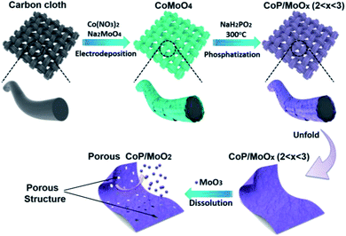
Herein, we firstly report on using molybdenum trioxide (MoO3) as an intermediary (pore former and MoO2 precursor) to in situ synthesize strongly coupled porous CoP/MoO2 hybrid thin films. The brief preparation route is illustrated in Scheme 1. Commercial carbon cloth (CC) was employed as a flexible substrate and its typical scanning electron microscopy (SEM) images are shown in Fig. S1.† CoMoO4 thin films were firstly coated on the surface of carbon cloth via a simple electrodeposition method (Fig. S2†). Then, CoMoO4 was selectively converted into CoP and MoOx (CoP/MoOx thin films, 2 < x < 3) through a custom-built low temperature phosphatization process. Finally, the porous CoP/MoO2 thin films can be conveniently obtained by suspending CoP/MoOx thin films in an alkaline solution. The cleverness of this kind of synthetic strategy lies in the fact that MoO3 in CoMoO4 could not be phosphided during the phosphatization process. Instead, a portion of MoO3 was reduced to MoO2, forming a mixture of MoO2 and MoO3, which can bring about many benefits. On the one hand, MoO3 can be easily removed in situ, which can not only maximize the exposure of active sites, but can also provide abundant channels, which is beneficial to fast electrolyte penetration/diffusion and improves the utilization rate of the catalyst. On the other hand, MoO2 and CoP are derived from homogeneous CoMoO4 and thus are strongly connected to each other, which is conducive to strengthening the synergy between MoO2 and CoP. Density Functional Theory (DFT) calculations also confirmed the positive impact, and show that the coupling of MoO2 can significantly optimize the H2O adsorption energy on the surface of CoP. In anticipation, the as-prepared porous CoP/MoO2 hybrid thin films were directly utilized as a catalyst electrode for the HER and exhibited an excellent catalytic performance with a negligible onset overpotential of 12 mV, only requiring a small overpotential of 41 mV to support a current density of 20 mA cm−2, which is almost comparable to the catalytic performance of the Pt/C benchmark.
Results and discussion
The composition and surface chemical state of the as-prepared samples were analyzed by means of X-ray photoelectron spectroscopy (XPS). The initial product can be marked as CoMoO4 according to the strong Co 2p, Mo 3d and O 1s signals in Fig. S3,† as well as the typical Raman spectrum in Fig. S4.†Fig. S5† presents the XPS spectra of the sample after phosphating. Specifically, the two typical peaks at 779.1 eV in Fig. S5a† and 129.7 eV in Fig. S5b† correspond well to Co 2p and P 2p of the CoP phase,20 indicating a successful composition transformation during the phosphatization process. Fig. S5c† shows the Mo 3d spectra for the phosphatized samples before and after alkali treatment. For the sample before alkali treatment (marked as CoP/MoOx), the two strong peaks situated at 234.2 eV and 231.2 eV correspond to Mo(IV) 3d3/2 and 3d5/2 of MoO2, and the other two peaks centered at 236.1 eV and 232.9 eV could be ascribed to Mo(VI) 3d3/2 and 3d5/2 of MoO3, respectively.21 The above results clearly show that Mo exists in the form of a mixed oxide (MoO3 and MoO2) in CoP/MoOx. The composition of the final product (marked as CoP/MoO2), which was collected after alkali treatment, was also investigated. The typical spectra are shown in Fig. S5† (upper position). The comparison result in Fig. S5† reveals the disappearance of Mo(VI) peaks in the final product, confirming the dissolution of MoO3 in KOH solution and thus the successful preparation of the CoP/MoO2 hybrid. This phenomenon is further confirmed by EDX results (Fig. S6†), in which the Mo peak intensity is obviously decreased after the sample is dipped in KOH solution. In addition, to explore the impact of electronic effect after the introduction of MoO2, the XPS spectrum of a single CoP was also studied for comparison (Fig. 1). From Fig. 1, it can be clearly observed that the binding energies of Co 2p and P 2p have an obvious positive shift after CoP is coupled with MoO2 (0.71 eV and 0.51 eV, respectively). This result confirms that there are strong electronic interactions between CoP and MoO2 in the CoP/MoO2 sample.
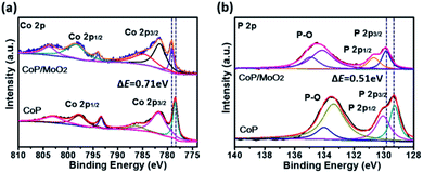 | ||
| Fig. 1 XPS spectra of porous CoP/MoO2 thin films and pure CoP thin films: (a) Co 2p spectra, (b) P 2p spectra. | ||
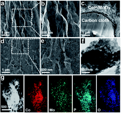
After chemical composition transformation, the morphologies and nanostructures of the CoP/MoOx and CoP/MoO2 samples were examined by SEM and transmission electron microscopy (TEM). Fig. 2a–c show that CoP/MoOx exists as thin films and is uniformly coated on the carbon cloth substrate. The SEM image of the cut surface in Fig. 2c reveals that the inner space of CoP/MoOx is a kind of cavity construction. Fig. 2d and e indicate that the CoP/MoO2 thin films have an obvious porous structure characteristic, which is a big difference from the initial state of CoP/MoOx thin films. The fabrication of a porous structure exactly corresponded to the dissolution of MoO3 in XPS results. The typical TEM image in Fig. 2f further confirms the porous and cavity structure of the CoP/MoO2 thin films. Such a porous structure is beneficial for exposing the active sites, which is confirmed by the electrochemically active surface area (ECSA, Fig. S7†), and is therefore favorable for the electrochemical catalytic process. The distribution of elements in porous CoP/MoO2 thin films were studied by high-angle annular dark-field scanning TEM (HAADF-STEM). The STEM images in Fig. 2g reveal that the elements Co, Mo, P and O are uniformly distributed in the porous CoP/MoO2 thin films, suggesting that CoP and MoO2 are evenly distributed and strongly coupled. Obviously, the uniformly mixed structure would strengthen the synergy between CoP and MoO2, beneficial to the electrochemical catalytic process. Additionally, the natural growth structure together with the good flexibility of carbon cloth should also impart excellent mechanical behavior and small contact resistance.
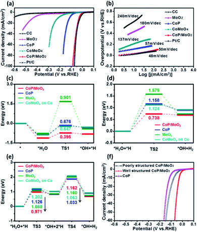
The HER performance of the porous CoP/MoO2 hybrid thin films was evaluated by linear sweep voltammetry (LSV) measurement in 1 M KOH solution with a typical three-electrode system. For comparison, LSV measurements of pure CC, CoP, MoO2, CoMoO4 and commercial Pt/C (20 wt%) were performed under identical conditions. The corresponding polarization curves after iR correction are shown in Fig. 3a. Electrochemical results show that the porous CoP/MoO2 thin films only require small overpotentials of 29, 41 and 87 mV to support current densities of 10, 20 and 100 mA cm−2, respectively. These values are very close to those of a Pt/C catalyst electrode and are superior to those of almost all the reported non-noble materials at similar current densities, such as CoP@NPMG, Co(OH)2@PANI thin films, MoP@NPCF/CC, amorphous Co–Ni sulfide and heterostructured Mo2C-MoOx (details can be seen in Table S1†).22–26 In contrast, the CoMoO4, MoO2 and CoP thin films suffer from a large overpotential, indicating a relatively poor HER catalytic activity. The comparison results suggest that the introduction of MoO2 should play an important role in prompting the HER activity of the CoP catalyst. To understand the enhanced HER activity of porous CoP/MoO2 thin films, Tafel analysis was employed to elucidate the possible mechanistic steps occurring on the catalyst electrode surface. The linear region of the Tafel plots is fitted to the Tafel equation (η = b![[thin space (1/6-em)]](https://www.rsc.org/images/entities/char_2009.gif) log
log![[thin space (1/6-em)]](https://www.rsc.org/images/entities/char_2009.gif) j + a, where j represents the current density and b is the Tafel slope).27 As shown in Fig. 3b, the Tafel slopes for the porous CoP/MoO2 thin films and the commercial Pt/C are ∼50 and ∼48 mV dec−1, respectively, significantly lower than the values of other catalyst electrodes. Such similar Tafel slopes suggest that the hydrogen production mechanisms of the CoP/MoO2 and Pt/C are identical. According to previous reports, the values correspond to the Volmer–Heyrovsky mechanism and electrochemical desorption is the rate-limiting step.28 These findings agree with the XPS characterization result, which confirms that the introduction of MoO2 can bring about strong electronic interaction with CoP. One possible conclusion is that the enhanced HER catalytic activity should be mainly attributed to the strong electronic interaction endowing the porous CoP/MoO2 thin films with an optimized H2O adsorption energy.
j + a, where j represents the current density and b is the Tafel slope).27 As shown in Fig. 3b, the Tafel slopes for the porous CoP/MoO2 thin films and the commercial Pt/C are ∼50 and ∼48 mV dec−1, respectively, significantly lower than the values of other catalyst electrodes. Such similar Tafel slopes suggest that the hydrogen production mechanisms of the CoP/MoO2 and Pt/C are identical. According to previous reports, the values correspond to the Volmer–Heyrovsky mechanism and electrochemical desorption is the rate-limiting step.28 These findings agree with the XPS characterization result, which confirms that the introduction of MoO2 can bring about strong electronic interaction with CoP. One possible conclusion is that the enhanced HER catalytic activity should be mainly attributed to the strong electronic interaction endowing the porous CoP/MoO2 thin films with an optimized H2O adsorption energy.
To deeply understand the higher HER activity of the CoP/MoO2 thin films compared to CoMoO4, CoP and MoO2, density functional theory (DFT) calculations were employed to study the H2O adsorption and dissociation energy on CoMoO4, CoP, MoO2 and CoP/MoO2 clusters (Fig. 3c–e), and the simplified cluster models and those clusters with H2O adsorption are shown in Fig. S8 and S9,† respectively. It is generally known that the HER in an alkaline system can be carried out through either the Volmer–Heyrovsky mechanism or the Volmer–Tafel mechanism.29,30 For the Volmer–Heyrovsky mechanism reaction process, the first step of the reaction is the Volmer catalytic process: H2O is adsorbed on the surface of the catalyst and then decomposed via catalysis into OH and H, which are kept adsorbed on the surface of the catalyst for subsequent reactions. During the process, a reaction barrier (TS1) must be overcome. The second step of the reaction is the Heyrovsky catalytic process: the adsorbed H2O and the H generated in the first step are reformed on the catalyst surface to produce OH and H2, where the reaction needs to overcome anther reaction energy barrier (TS2). For the Volmer–Tafel mechanism reaction, the first step is the Volmer catalytic process; however, the second step of the reaction is the Tafel catalytic process: the adsorbed H2O and the H generated in the first step are reformed on the surface of the catalyst to form OH and H, and then two H are further combined into H2. The Tafel catalytic process needs to overcome two barriers, i.e. TS3 and TS4. It can be seen that both Volmer–Heyrovsky and Volmer–Tafel reaction paths in alkaline systems involve the adsorption of H2O and intermediate states, the overcoming of reaction barriers and the desorption of products. Therefore, the adsorption energy, the reaction energy barrier and the desorption of the product all greatly affect the activity of the catalyst.
By comparing CoP/MoO2 with CoP, MoO2 and CoMoO4 on Co (Co is calculated to be the active site for CoMoO4; for detailed information see ESI Fig. S10†), it can be found that CoP/MoO2 has the maximum adsorption energy for H2O and the intermediate state through either the Volmer–Heyrovsky reaction path or the Volmer–Tafel reaction path, and the energy barriers (TS1, TS2 and TS3) to be overcome on CoP/MoO2 are also the minimum. These indicate that H2O is more likely to adsorb and decompose on CoP/MoO2. On the other hand, the favorable adsorption energy of CoP/MoO2 for H2 means that H2 is more easily desorbed from CoP/MoO2, thus facilitating the continuous reaction. It is worth noting that for the Tafel reaction path taken on CoP/MoO2, two high barriers (TS3 and TS4) need to be overcome; however, for the Heyrovsky pathway taken on CoP/MoO2, only one reaction barrier needs to be overcome with a much lower energy (TS2 < TS3, TS4). Therefore, the HER process is more likely to take the Volmer–Heyrovsky reaction path on CoP/MoO2, which is consistent with the Tafel value (50 mV dec−1) displayed by CoP/MoO2. All the above comparison results show that CoP/MoO2 is most beneficial to the HER process, which well corresponds with the electrochemical results (Fig. 3a and b).
In addition, it has been mentioned before that one of the main innovations in this work is the use of MoO3 as a pore-forming agent. To illustrate the effect of porous structure on catalytic ability, a set of comparison experiments involving non-porous CoP/MoO2 thin films were carried out. It should be pointed out that the non-porous CoP/MoO2 thin films were obtained via an additional continuous repeated phosphating. The typical SEM (Fig. S11†) and XPS characterization results (Fig. S12†) reveal that the MoO3 can be completely converted into MoO2 after repeatedly phosphating, and thus no MoO3 can be dissolved, making it unable to form a porous structure. Polarization curves in Fig. 3f reveal that the HER catalytic performance of both porous and non-porous CoP/MoO2 thin films is better than that of the pure CoP thin film catalyst, which is in agreement with the results of DFT calculation. However, the non-porous CoP/MoO2 thin films exhibit significantly lower catalytic activity than porous CoP/MoO2 thin films. This result indicates that porosity is another crucial parameter dominating HER activity, which can not only endow porous CoP/MoO2 with a more exposed active surface but can also enable rapid diffusion of species during the reactions.
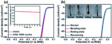
Stability is another important aspect for the evaluation of catalysts. Here an accelerated durability test on the porous CoP/MoO2 thin film electrode was performed by conducting continuous linear potential sweeps. The comparison results before and after 5000 cycles are shown in Fig. 4a. It can be clearly seen that the onset overpotential shows almost no change after 5000 cycles; even when current density is increased to 100 mA cm−2, the overpotential is only slightly increased by 14 mV, indicating good stability of the catalyst electrode. The chronopotentiometry experiment result also confirmed the good stability of the CoP/MoO2 thin film electrode (inset, Fig. 4a), which shows a relatively stable current density with a mere 3.4% decay after 10 h continuous operation. In view of the SEM image of the material after the stability test (Fig. S13†), the good catalytic stability of the porous CoP/MoO2 thin films can be mainly attributed to their excellent structural stability. Furthermore, considering the use of flexible carbon cloth as a substrate, the flexibility performance of CoP/MoO2-CC was also studied. To be specific, the working electrode was tested under different distortions, including normal, bending, rolling and recovering states (inset, Fig. 4b). The corresponding polarization curves for the HER are shown in Fig. 4b. The almost completely overlapped polarization curves illustrate that the catalytic activity of the CoP/MoO2-CC wasn't affected by deformation, indicating an excellent mechanical stability. Obviously, this feature will be able to effectively resist the product gas impact on the catalyst electrode, especially when there is a lot of gas evolution.
Conclusions
In summary, by using MoO3 as an intermediary, we have successfully synthesized a strongly coupled porous CoP/MoO2 HER electrocatalyst. This delicate design not only strengthens the electronic synergy and maximizes the exposure of the active sites, but also contributes to fast electrolyte penetration/diffusion. Owing to these advantages, the as-obtained porous CoP/MoO2 thin films exhibited excellent HER catalytic performance with a negligible onset overpotential of 12 mV and a small Tafel slope of 50 mV dec−1, which should be one of the best catalytic activities among the reported non-precious metal catalysts for the HER to date. Our research has confirmed that the enhanced electronic effect derived from the coupling of MoO2 can efficiently optimize the H2O adsorption energy on the surface of CoP, thus promoting hydrogen evolution. The collection of results also demonstrated that the porous structure has great influence on the hydrogen evolution process, and is even one of the decisive factors. This work provides new insight for the design of high-efficiency HER catalysts. Moreover, the synthesis strategy proposed here is not limited to the preparation of the porous CoP/MoO2 hybrid, and can be easily extended to the preparation of other porous composite materials.Experimental
Fabrication of porous CoP/MoO2 thin films
All chemical reagents used in this study were of analytical (AR) grade. Electrochemical deposition was carried out in a simple two-electrode electrolytic cell via galvanostatic electrodeposition, and a graphite electrode was used as a counter electrode (spectral grade). The details of the fabrication route are described below: (1) Commercial carbon cloth (CC, AvCarb 1071 HCB, 1 cm × 1 cm) was employed as a substrate. CoMoO4 thin films were first electrodeposited from aqueous solutions of 0.02 M Co(NO3)2, 0.02 M Na2MoO4, and 0.05 M NH4NO3 with a current density of 0.6 mA cm−2 for 30 min; (2) CoP/MoOx-CC was obtained by heating CoMoO4 thin films under an atmosphere of gaseous sodium hypophosphite at 300 °C in an Ar flow for 2 hours; (3) finally, porous CoP/MoO2 thin films were conveniently obtained by suspending CoP/MoOx thin films in 1 M KOH solution. Additionally, for comparison, CoP thin films were also prepared by the same route without Na2MoO4.Characterization
The morphologies and nanostructures of all the samples were characterized by scanning electron microscopy (SEM, FEI Nano430) and transmission electron microscopy (TEM, JEOL 2100F). Raman spectra were collected using a Horiba Jobin Yvon LabRam Aramis Raman spectrometer equipped with a 632.8 nm laser. The composition and surface chemical state of the as-prepared samples were analyzed by X-ray photoelectron spectroscopy (XPS) using an ESCALAB 250 spectrometer (Thermo Fisher Scientific). All of the XPS spectra were corrected using the C 1s peak at 284.8 eV.Electrochemical measurements
All of the electrochemical tests were carried out on a standard electrochemical workstation (IM6ex). Cyclic Voltammetry (CV) and linear sweep voltammetry (LSV) measurements were conducted in 1 M KOH solution with a typical three-electrode system. Pt foil served as the counter electrode and a saturated calomel electrode (SCE) was used as the reference electrode. In this paper, all mentioned potentials were calibrated versus the reversible hydrogen electrode (RHE), according to the equation E(RHE) = E(SCE) + 0.2412 + 0.05916 pH.Electrochemical capacitance was determined using CV measurements. The potential range was typically a 0.1 V window centered at the open-circuit potential (OCP) of the system. CV measurements were conducted by sweeping the potential across the non-faradaic region with different scan rates: from 2 mV s−1 to 10 mV s−1. All measured current in this non-faradaic potential region is assumed to be ascribed to double-layer charging. The charging current, ic, is then measured from CVs at multiple scan rates. The double-layer charging current is equal to the product of the scan rate, v, and the electrochemical double-layer capacitance, CDL, as given by eqn (1).
| ic = vCDL | (1) |
Thus, a plot of ic as a function of v yields a straight line with a slope equal to CDL. The electrochemically active surface area (ECSA) of catalysts is calculated from the double-layer capacitance according to eqn (2):
| ECSA = CDL/Cs | (2) |
First-principles calculations
First-principles calculations in the framework of density functional theory, including structural and electronic performance calculations, were carried out based on the Cambridge Sequential Total Energy Package known as CASTEP. The exchange–correlation functional under the generalized gradient approximation (GGA) with norm-conserving pseudopotentials and Perdew–Burke–Ernzerhof functional was adopted to describe the electron–electron interaction. An energy cutoff of 750 eV was used and a k-point sampling set of 5 × 5 × 1 was tested to be converged. A force tolerance of 0.01 eV Å−1, energy tolerance of 5.0 × 10⁻⁷ eV per atom and maximum displacement of 5.0 × 10⁻⁴ Å were considered. The models of amorphous CoP, CoMoO4, MoO2 and CoP/MoO2 were built after relaxing the crystal surface at 2000 K, and the ordered atomic arrangement was damaged. The vacuum space along the z direction was set to be 15 Å, which is enough to avoid interaction between the two neighboring images. All atoms were relaxed.Adsorption energy ΔE of an A group on the surface of substrates is defined as
| ΔE = E*A – (E*+ EA) |
Conflicts of interest
There are no conflicts to declare.Acknowledgements
We gratefully acknowledge the funding from the National Natural Science Foundation of China (21776099 and 21406078), the Guangdong Special Support Program (2017TQ04N086), the Natural Science Foundation of Guangdong Province (2019A1515011579) and the Postdoctoral Innovative Talents Support Program (BX20200315).References
- J. A. Turner, Science, 1999, 285, 687–689 CrossRef CAS PubMed.
- Z. Zeng, C. Tan, X. Huang, S. Bao and H. Zhang, Energy Environ. Sci., 2014, 7, 797–803 RSC.
- J. Duan, S. Chen, M. Jaroniec and S. Z. Qiao, ACS Nano, 2015, 9, 931–940 CrossRef CAS PubMed.
- Z. Chen, X. Duan, W. Wei, S. Wang and B.-J. Ni, J. Mater. Chem. A, 2019, 7, 14971–15005 RSC.
- W. Wang, M. Xu, X. Xu, W. Zhou and Z. Shao, Angew. Chem., Int. Ed., 2019, 58, 2–19 CrossRef.
- D.-Y. Wang, M. Gong, H.-L. Chou, C.-J. Pan, H.-A. Chen, Y. Wu, M.-C. Lin, M. Guan, J. Yang and C.-W. Chen, J. Am. Chem. Soc., 2015, 137, 1587–1592 CrossRef CAS PubMed.
- X. Wang, Q. He, L. Song, M. Jaroniec, Y. Zheng and S.-Z. Qiao, J. Mater. Chem. A, 2019, 7, 13635–13640 RSC.
- L. Huang, X. Zhang, Q. Wang, Y. Han, Y. Fang and S. Dong, J. Am. Chem. Soc., 2018, 140, 1142–1147 CrossRef CAS PubMed.
- Y. Chen, G. Yu, W. Chen, Y. Liu, G.-D. Li, P. Zhu, Q. Tao, Q. Li, J. Liu, X. Shen, H. Li, X. Huang, D. Wang, T. Asefa and X. Zou, J. Am. Chem. Soc., 2017, 139, 12370–12373 CrossRef CAS PubMed.
- Z. Pu, C. Zhang, I. S. Amiinu, W. Li, L. Wu and S. Mu, ACS Appl. Mater. Interfaces, 2017, 9, 16187–16193 CrossRef CAS PubMed.
- J. Tian, Q. Liu, N. Cheng, A. M. Asiri and X. Sun, Angew. Chem., Int. Ed., 2014, 53, 9577–9581 CrossRef CAS PubMed.
- Y.-R. Zheng, M.-R. Gao, Z.-Y. Yu, Q. Gao, H.-L. Gao and S.-H. Yu, Chem. Sci., 2015, 6, 4594–4598 RSC.
- Y. F. Zeng, Y. Y. Wang, G. Huang, C. Chen, L. Huang, R. Chen and S. Wang, Chem. Commun., 2018, 54, 1465–1468 RSC.
- C. Sun, J. Zeng, H. Lei, W. Yang and Q. Zhang, ACS Sustainable Chem. Eng., 2018, 7, 1529–1537 CrossRef.
- Y.-Y. Ma, C.-X. Wu, X.-J. Feng, H.-Q. Tan, L.-K. Yan, Y. Liu, Z.-H. Kang, E.-B. Wang and Y.-G. Li, Energy Environ. Sci., 2017, 10, 788 RSC.
- Y. J. Tang, M. R. Gao, C. H. Liu, S. L. Li, H. L. Jiang, Y. Q. Lan, M. Han and S. H. Yu, Angew. Chem., Int. Ed., 2015, 54, 12928–12932 CrossRef CAS PubMed.
- X. Xie, L. Lin, R.-Y. Liu, Y.-F. Jiang, Q. Zhu and A.-W. Xu, J. Mater. Chem. A, 2015, 3, 8055–8061 RSC.
- S. Li, L. Zhao, S. Lei, A. Liu, J. Chen, C. Li, H. Wu and L. Lin, Nanoscale, 2020, 12, 5003–5013 RSC.
- L. Yang, W. Zhou, D. Hou, K. Zhou, G. Li, Z. Tang, L. Li and S. Chen, Nanoscale, 2015, 7, 5203–5208 RSC.
- F. H. Saadi, A. I. Carim, E. Verlage, J. C. Hemminger, N. S. Lewis and M. P. Soriaga, J. Phys. Chem. C, 2014, 118, 29294–29300 CrossRef CAS.
- Y. Jin, H. Wang, J. Li, X. Yue, Y. Han, P. K. Shen and Y. Cui, Adv. Mater., 2016, 28, 3785–3790 CrossRef CAS PubMed.
- Y. Liu, Y. Zhu, J. Shen, J. Huang, X. Yang and C. Li, Nanoscale, 2018, 10, 2603–2612 RSC.
- J. X. Feng, L. X. Ding, S. H. Ye, X. J. He, H. Xu, Y. X. Tong and G. R. Li, Adv. Mater., 2015, 27, 7051–7057 CrossRef CAS PubMed.
- J.-T. Ren, L. Chen, C.-C. Weng and Z.-Y. Yuan, Mater. Chem. Front., 2019, 3, 1872–1881 RSC.
- W. Lu, X. Li, F. Wei, K. Cheng, W. Li, Y. Zhou, W. Zheng, L. Pan and G. Zhang, ACS Sustainable Chem. Eng., 2019, 7, 12501–12509 CAS.
- L. He, W. Zhang, Q. Mo, W. Huang, L. Yang and Q. Gao, Angew. Chem., Int. Ed., 2019, 59, 3544–3548 CrossRef PubMed.
- L. Yang, W. Zhou, J. Lu, D. Hou, Y. Ke, G. Li, Z. Tang, X. Kang and S. Chen, Nano Energy, 2016, 22, 490–498 CrossRef CAS.
- M. G. de Chialvo and A. Chialvo, J. Electroanal. Chem., 1994, 372, 209–223 CrossRef.
- S. Chen, Z. Wei, X. Qi, L. Dong, Y.-G. Guo, L. Wan, Z. Shao and L. Li, J. Am. Chem. Soc., 2012, 134, 13252–13255 CrossRef CAS PubMed.
- Z. Chen, X. Duan, W. Wei, S. Wang and B.-J. Ni, J. Mater. Chem. A, 2019, 7, 14971–15005 RSC.
Footnotes |
| † Electronic supplementary information (ESI) available. See DOI: 10.1039/d0ta03736b |
| ‡ J. Wang and H. Cheng contributed equally to this work. |
| This journal is © The Royal Society of Chemistry 2020 |

