ZIF-67-based catalysts for oxygen evolution reaction
Hui
Wen†
 ab,
Shengqi
Zhang†
 ab,
Tao
Yu
ab,
Ziyu
Yi
ab and
Rui
Guo
ab,
Tao
Yu
ab,
Ziyu
Yi
ab and
Rui
Guo
 *acb
*acb
aSchool of Materials Science and Engineering, Northeastern University, Shenyang 110819, China. E-mail: guorui@neuq.edu.cn
bSchool of Resources and Materials, Northeastern University at Qinhuangdao, Qinhuangdao 066004, China
cKey Laboratory of Advanced Energy Materials Chemistry (Ministry of Education), College of Chemistry, Nankai University, Tianjin 300071, China
First published on 14th June 2021
Abstract
As a new type of crystalline porous material, the imidazole zeolite framework (ZIF) has attracted widespread attention due to its ultra-high surface area, large pore volume, and unique advantage of easy functionalization. Developing different methods to control the shape and composition of ZIF is very important for its practical application as catalyst. In recent years, nano-ZIF has been considered an electrode material with excellent oxygen evolution reaction (OER) performance, which provides a new way to research electrolyzed water. This review focuses on the morphological engineering of the original ZIF-67 and its derivatives (core–shell, hollow, and array structures) through doping (cation doping, anion doping, and co-doping), derivative composition engineering (metal oxide, phosphide, sulfide, selenide, and telluride), and the corresponding single-atom catalysis. Besides, combined with DFT calculations, it emphasizes the in-depth understanding of actual active sites and provides insights into the internal mechanism of enhancing the OER and proposes the challenges and prospects of ZIF-67 based electrocatalysts. We summarize the application of ZIF-67 and its derivatives in the OER for the first time, which has significantly guided research in this field.
1 Introduction
The consumption of a large number of fossil fuels and the resulting greenhouse effect has prompted researchers to have a strong research interest in the development of clean energy conversion technologies.1–5 In particular, the electrolysis of water to produce hydrogen is a convenient and environmentally friendly way to generate clean hydrogen energy.6–9 However, the slow kinetics of anodic oxygen generation severely limits the hydrogen release reaction on the cathode.10–12 Therefore, it is necessary to design electrocatalysts with a high-efficiency OER to improve the efficiency of water decomposition.13–15 So far, IrO2 and RuO2 are catalysts with the highest OER activity in alkaline media.16 However, both IrO2 and RuO2 are easily oxidized, and their high cost has seriously hindered the commercialization of zinc–air batteries and overall water splitting.17–20 In recent years, researchers have done a lot of work to improve the performance of cheap electrocatalysts, hoping to replace precious metal-based catalysts.21–23 Transition metal-based MOF derivatives are considered as promising alternative catalysts for the OER.24 Researchers found that on this basis, the rational design and construction of the structure and composition of the catalyst can further improve the electrocatalytic performance of the OER.25–27As a new type of crystalline and microporous material, the metal–organic framework (MOF), with a large surface area, unique porosity, and customizable functionality, is extremely attractive for catalysis.28–30 Using active metal centers and functionalized organic ligands, MOFs combine the good properties of these two catalysts.31,32 MOFs have broad prospects as OER electrode catalysts, because the pores and open channels of the MOF can provide storage space for the electrolyte, promote the diffusion of reactants, and promote the transport/release of generated oxygen. In addition, the evenly distributed metal cations in the MOF and the ligands in the framework are appropriately adjusted to effectively improve the ability of the OER catalyst.33
Although many types of MOF have been developed to catalyze the oxygen release reaction, most MOFs cannot be used in practical applications due to their poor stability. While, ZIF has excellent stability due to its special structure (the skeleton structure of ZIF-67 is composed of metal Co2+ ions and N atoms of 2-methylimidazole, which form tetrahedral structural units by hybridizing with the four-coordinate SOD topology). In addition, ZIF is a very attractive sub-category. It has the advantages of the large specific surface area of a MOF, high porosity, adjustable pore structure and the chemical and thermal stability of traditional zeolite materials.34–36 Although there have still been relatively few studies based on ZIF catalysts in recent years, they have shown a gradual growth trend.37,38 Although ZIF-67 and its derivatives show excellent OER catalytic performance, there is still a gap in the practical application of overall hydrolysis. In addition, ZIF-8 is an indispensable isostructural MOF of ZIF-67, as many nanocatalysts utilize the structural difference/similarity of this pair of MOFs in constructing unique structures, but ZIF-8 is rarely used for OER catalysis.39
This review introduces the applications of ZIF-67 and its derivatives in catalytic regulation of the OER through two aspects: structural engineering and component engineering. In addition, by summarizing DFT calculations, we can give a deeper insight into its catalytic mechanism for the OER process, which provides a theoretical basis for more rational design of OER catalysts. Finally, the application prospects of ZIF-67 and its derivatives in OER catalysis are proposed.
2 Preparation and properties of ZIF-67
2.1 Preparation of ZIF-67
T-ZIF-67 is a commonly used catalyst in most studies of electrocatalytic OERs based on ZIF-67, while H-ZIF-67 and M-ZIF-67 are rarely used. Usually, the synthesis method of T-ZIF-67 (Fig. 1a) reported by Luo et al.40 can be used as a reference to synthesize a purple product. Moreover, the synthesis of M-ZIF-67 (Fig. 1b) was carried out by only replacing Co(NO3)2 with CoSO4 on the basis of the synthesis of T-ZIF-67; the synthesis of H-ZIF-67 (Fig. 1c) is based on the synthesis of M-ZIF-67 with PVP. | ||
| Fig. 1 SEM images of (a) T-ZIF-67, (b) M-ZIF-67, and (c) H-ZIF-67.40 Copyright @2017, The Author(s). | ||
2.2 OER performance of ZIF-67
For the OER of ZIF-67, Wang et al.41 proposed a new concept that could realize the engineering of the imidazole zeolite framework (ZIF-67) as a two-dimensional structure with exposed (002) faces in the MOF. They found that in the (002), (011), and (111) planes, the (002) plane of ZIF-67 showed the best OER activity (Fig. 2a and b). In contrast, it was found that ZIF-67 nanocrystals with a size comparable to the main exposed (011) plane had poor OER activity. Based on the experimental results and density functional theory (DFT) (Fig. 2c and d), they revealed the influence of the crystal face on the OER performance of ZIF-67.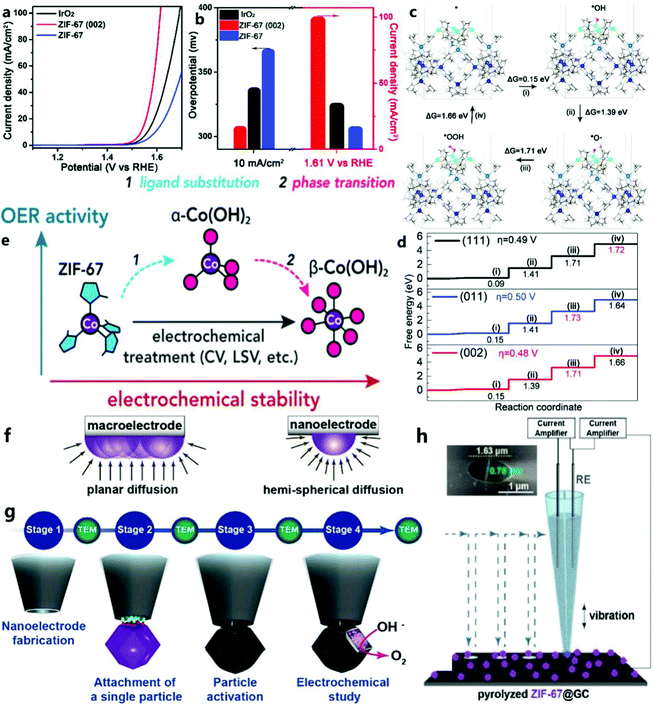 | ||
| Fig. 2 (a) Linear sweep voltammetry plots of commercial IrO2, ZIF-67 (002) and ZIF-67, (b) and the overpotential and current density of the corresponding catalysts at 10 mA cm−2. (c) The surface energy level of the OER process of ZIF-67 (002). Metal Co is blue, O is red, and H is white. (d) The standard free energy step diagram of the OER process on the (002), (011), and (111) planes of ZIF-67.41 Copyright © 2020, Royal Society of Chemistry. (e) Structure and morphological evolution of MOF (zeolite imidazolate skeleton ZIF-67) determined by cyclic voltammetry and amperometric methods.42 Copyright © 2020, American Chemical Society. (f) Illustration of diffusion flux around a macroelectrode and a nanoelectrode. (g) Flowchart of the various stages involved in the study of the MOF-derived CoN/C nanoparticle.43 Copyright © 2019 Wiley-VCH Verlag GmbH & Co. KGaA, Weinheim. (h) Typical SECCM setup and SEM image of the double-barrel nanocapillary used as the SECCM tip (inset).44 Copyright © 2019 The Authors. Published by Wiley-VCH Verlag GmbH & Co. KGaA. | ||
In addition, Table 1 shows that, although pure ZIF-67 shows poor OER catalytic performance due to its low conductivity, it is very important to understand what is the real catalytically active site in the catalytic process. For example, Zheng et al.42 used in situ spectroelectrochemical methods to prove that the true catalytically active sites in the catalytic process of ZIF-67 are α-Co(OH)2 and CoOOH, not metal atom nodes. The changes to ZIF-67 during the catalytic process are shown in Fig. 2e.
| Catalyst | Substrate | Overpotential/mV | Tafel/mV dec−1 | Electrolyte | Scan rate/mV s−1 | Ref. |
|---|---|---|---|---|---|---|
| ZIF-67 | RDE | 334 | 105 | 1 M KOH | 5 | 45 |
| ZIF-67 | Glassy carbon electrode (GCE) | 400 | 235 | 1 M KOH | 5 | 46 |
| ZIF-67 | Glassy carbon electrode (GCE) | 420 | — | 1 M KOH | 1 | 47 |
| ZIF-67 | RDE | 400 | 96 | 1 M KOH | 5 | 48 |
| ZIF-67 | Glassy carbon electrode (GCE) | 390 | 88.3 | 1 M KOH | 5 | 49 |
| ZIF-67 | Glassy carbon electrode (GCE) | 352 | 82 | 1 M KOH | 5 | 50 |
| ZIF-67 | Glassy carbon electrode (GCE) | 410 | 83.8 | 1 M KOH | 2 | 51 |
| ZIF-67 | Glassy carbon electrode (GCE) | 408 | 128.2 | 1 M KOH | 5 | 52 |
| ZIF-67 | Glassy carbon electrode (GCE) | 530 | 147 | 1 M KOH | 2 | 53 |
| ZIF-67 | NF | 400 | 98 | 1 M KOH | 5 | 54 |
| ZIF-67 | Glassy carbon electrode (GCE) | 530 | 125.5 | 0.1 M KOH | 5 | 55 |
| ZIF-67 | Glassy carbon electrode (GCE) | 546 | 74 | 1 M KOH | 5 | 56 |
| ZIF-67 | Glassy carbon electrode (GCE) | 480 | 122 | 0.1 M KOH | 5 | 57 |
In order to accurately show the OER performance of ZIF-67 derivatives, Schuhmann et al.43 evaded the overall effect and film effect of the macroscopic analysis of the electrode reaction through an electrochemical study of single nanoparticles (Fig. 2f and g). Thus, the electrocatalytic performance of the OER and its catalytic process can be measured more accurately. According to reports, this unprecedented method can be used to understand the electrocatalytic behavior of individual nanoparticles without affecting the overall and thin-film effects. This research program consolidates the potential of such architectures to establish the basic electrocatalytic parameters of nanoparticles and structure–property relationships that are not affected by macroscopic membrane effects. In addition to obtaining the basic electrocatalytic properties of nanoparticles, these nanocomponents can also be used as a powerful platform for studying reactions involving changes in the local electrode–electrolyte environment, which is not possible on large electrodes. Subsequently, the group44 reported studies of Co–N-doped C composite particles derived from the ZIF-67 relative to the OER using a scanning electrochemical cell microscope (SECCM) (Fig. 2h). By using the interference-free Os compound as a standard for the free-diffusion internal redox potential, the problem of surface wetting and potential drift can be solved, and SECCM can be successfully applied in alkaline media.
2.3 Summary
This section mainly introduces three types of ZIF-67 (T-ZIF-67, M-ZIF-67, H-ZIF-67) for the electrocatalytic OER. Among them, T-ZIF-67 is the most commonly used, and an efficient OER is achieved by shaping the zeolite imidazolate skeleton (ZIF-67) into a 2D structure with exposed (002) facets. It can be found that the real active sites of ZIF-67 are α-Co(OH)2 and CoOOH. In addition, the OER catalytic process of ZIF-67 derivatives and the study of its single nanoparticle electrocatalytic behavior are also described.3 OER catalysis of ZIF-67 with different morphological structures
As we all know, improving the electrocatalytic performance through composition optimization and morphological modification are two effective and feasible methods. In addition, the conductivity and stability of MOF and MOF-derived catalysts are issues of great concern, and these problems can be solved to a certain extent through composition or morphology engineering. It can be found that the main purpose of structural or morphological engineering is to expand the active surface area to expose more active sites. For example, the controlled synthesis of a core–shell structure, a hollow structure and an array can result in an excellent OER performance. The morphological engineering of MOF and MOF derivatives is very important to increase the density of active sites, control the uniform distribution of active materials, prevent nanoparticle aggregation, promote electron/mass transfer, and produce synergistic effects between active materials and the matrix.58 However, the low intrinsic conductivity and easy self-aggregation of ZIF-67 derivatives usually result in high overpotentials. The result is insufficient exposure of ZIF-67 surface active sites and slow interfacial reaction kinetics. A single derivative of ZIF-67 usually exhibits an unsatisfactory electrochemical performance.59 Therefore, it is necessary to optimize the morphology to improve the catalytic performance of ZIF-67 and its derivatives.3.1 Core–shell structure
Traditional catalytic reactions mostly occur on the surface of the solid phase, so the total surface area of the active phase has a great influence on the reaction rate. This also shows that the surface structure will affect the catalytic activity and its selectivity, and appropriately increasing the specific surface area can increase the catalytic activity. The study found that the catalyst with a core–shell structure could maintain the catalytic activity well.60–62 The structure of the catalyst has the advantages of large specific surface area and large pore size, which can solve the problem of nanomaterials easily agglomerating. Furthermore, because the boundary between the core and the shell is more obvious, the reaction ratio is more independent, there are more catalytically active sites, and the coating between materials maximizes the synergistic catalysis effect.63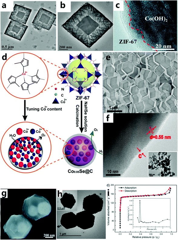 | ||
| Fig. 3 (a and b) TEM images of Co(OH)2-1.64 Copyright © 2019 Elsevier Inc. All rights reserved. (c) HRTEM images of the EG/Co(OH)2/ZIF-67 hybrid.65 Copyright © 2018, Royal Society of Chemistry. (d) Schematic diagram of the synthesis of Co0.85Se@C nanoparticles. (e) SEM image of ZIF-67. (f) HRTEM image of ZIF-Co0.85Se. Inset: low-resolution TEM image.66 Copyright © 2016, American Chemical Society. (g) SEM images of ZIF-67@Fe3O4 nanoparticles.67 Copyright © 2019, Royal Society of Chemistry. (h) TEM images of HHTP@ZIF-67. (i) The Brunauer–Emmett–Teller (BET) specific surface area and the corresponding pore size distribution plot (inset) of HHTP@ZIF-67.46 Copyright © 2018 Wiley-VCH Verlag GmbH & Co. KGaA, Weinheim. | ||
In addition, ZIF-67 or its derivatives can also be used as a shell for the catalyst. This not only increases the specific surface area but also protects the active sites of the reaction and increases its electrical conductivity. For example, Hou et al.65 used a new gas-phase hydrothermal method to synthesize ultra-thin cobalt-based ZIF-67 nanosheets on a vertically arranged Co(OH)2 nanosheet array. Ultra-thin ZIF-67 nanosheets are grown on the surface of Co(OH)2 sheets (with a thickness of about 5 nm), forming a core–shell structure (Fig. 3c). The excellent OER performance of this catalyst is due to inherent excellent electrical conductivity of exfoliated graphene foil and the synergistic effect between Co(OH)2 and the ZIF-67 interface, thereby accelerating the charge transfer and mass transfer process. Carbon material with excellent conductivity is another material to be used as a shell to improve the conductivity of the catalyst to endow the catalyst with an excellent OER performance. For example, Zheng et al.66 chose cobalt-based ZIF-67 as the precursor of cobalt and carbon, and then converted them into Co0.85Se nanoparticles (called ZIF-Co0.85Se) through selenization and subsequent calcination (Fig. 3d). As-prepared ZIF-Co0.85Se has an ultra-thin carbon shell layer (Fig. 3e and f), which is beneficial for improved conductivity and catalytic activity of the catalyst. The Co3+- and carbon-rich layer structure can provide sufficient active centers, good electrical conductivity and effective charge transport during the catalytic process, so as to achieve excellent OER catalytic performance. Meanwhile, they found that organic compounds as the core–shell structure could also effectively improve the specific surface area of the catalyst. For instance, Qin et al.67 described hybrid electrocatalysts with strongly coupled metal (Co–Fe) polyphenol networks (MPNs) and Fe3O4 nanoparticles (Fig. 3g). These catalysts were prepared through tannic acid-mediated conversion of the surface layer of ZIF-67@Fe3O4 synthesized initially during the selective conversion process, so that the core–shell nanoparticles were uniformly covered by the organic MPN layer. The MPN layer is composed of metal phenolic compounds rich in molecular metal hydroxide (M–OH, M–O–M) centers, which increase the electrochemical surface area by about four times. Pang et al.46 grew π-conjugated organic molecules in situ on ZIF-67 (HHTP@ZIF-67) by the hot solvent method (Fig. 3h). HHTP@ZIF-67 has a large specific surface area (Fig. 3i), leading to a great improvement in the OER catalytic performance.
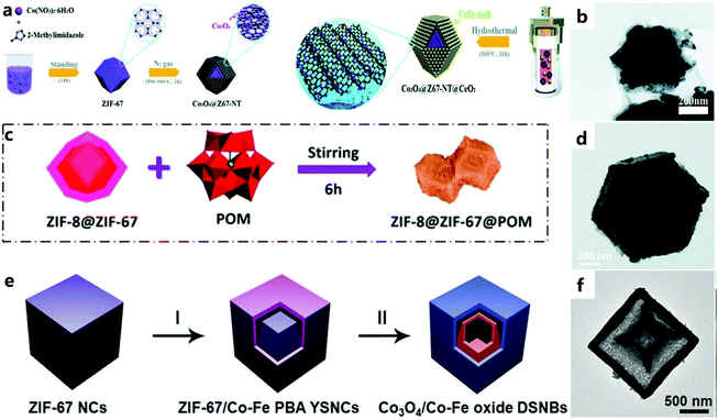 | ||
| Fig. 4 (a) Synthesis route for the Co3O4@Z67-NT@CeO2 composites. (b) TEM images of Co3O4@Z67-N700@CeO2.68 Copyright © 2019, Royal Society of Chemistry. (c) Schematic diagram for the synthesis of ZIF-8@ZIF-67@POM. (d) TEM image of ZIF-8@ZIF-67@POM.69 Copyright © 2019, Royal Society of Chemistry. (e) Schematic illustration of the formation process of Co3O4/Co–Fe oxide DSNBs. (f) TEM images of Co3O4/Co–Fe oxide DSNBs.70 Copyright © 2018 Wiley-VCH Verlag GmbH & Co. KGaA, Weinheim. | ||
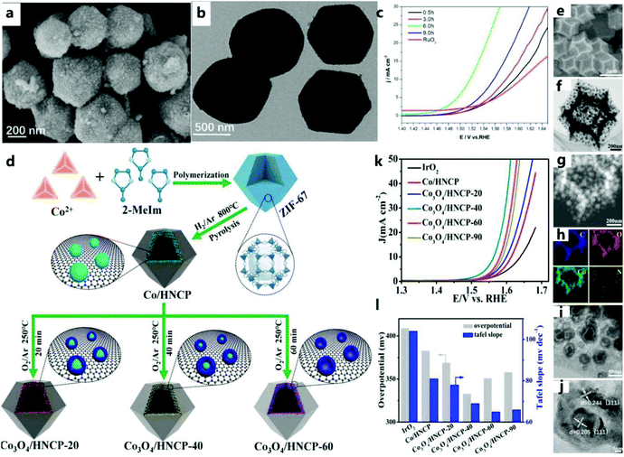 | ||
| Fig. 5 (a) SEM and (b) TEM images of 6-ZIF-67@POM. (c) The OER polarization curve of the catalyst in 1 M KOH solution at a scan rate of 2 mV s−1.72 Copyright @ 2019, American Chemical Society. (d) Schematic diagram of the synthesis of a series of Co–Co3O4 based nanostructures embedded in a hollow nitrogen-doped carbon polyhedron. (e–j) SEM, TEM, STEM, EDS mapping, and HRTEM images of Co3O4/HNCP-40, (k) LSV curves, (l) plot summarizing Tafel results and overpotentials at j = 10 mA cm−2.73 Copyright @ 2018, American Chemical Society. | ||
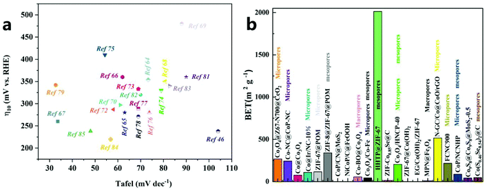 | ||
| Fig. 6 (a) OER activity comparison graph showing the Tafel slope at an overpotential of 10 mA cm−2 for different catalysts. (b) Comparison of BET/BJH results for different catalysts. | ||
| Core–shell structure | Substrate | Electrolyte | Overpotential/mV | Tafel/mV dec−1 | BET (m2 g−1)/BJH | Current density/mA cm−2 | Ref. |
|---|---|---|---|---|---|---|---|
| Co3O4@Z67-N700@CeO2 | GCE | 2–0.1 M KOH | 350 | 80.7 | 267.27/micropores | 10 | 68 |
| Co-NC@CoP-NC | GCE | 0.1 M KOH | 330 | 79 | 243/micropores | 10 | 74 |
| Co@Co3O4 | RDE | 0.1 M KOH | 410 | 54.3 | 76 | 10 | 75 |
| Co@Ir/NC-10% | RRDE | 1 M KOH | 280 | 73.8 | 108.45/micropores | 10 | 76 |
| ZIF-67@POM | GCE | 1 M KOH | 287 | 58 | 116/micropores | 10 | 72 |
| ZIF-8@ZIF-67@POM | GCE | 2–1 M KOH | 480 | 88 | 340/mesopores | 10 | 69 |
| CoP/CN@MoS2 | (GC) RDE | 1 M KOH | 289 | 69 | — | 10 | 77 |
| NiCoP/C@FeOOH | GCE | 1 M KOH | 271 | 69 | — | 10 | 78 |
| Co-BO@Co3O4 | GCE | 1 M KOH | 342 | 32.7 | 55.08/macropores | 10 | 79 |
| Co3O4/Co–Fe | GC–RDE | 1 M KOH | 297 | 61 | 43.3/micropores/mesopores | 10 | 70 |
| HHTP@ZIF-67 | GCE | 1 M KOH | 238 | 104 | 2013.9/mesopores | 10 | 46 |
| ZIF-Co0.85 Se@C | GC–RDE | 1 M KOH | 360 | 62 | 13.56 | 10 | 66 |
| Co3O4/HNCP-40 | GCE | 1 M KOH | 333 | 69 | 204/micropores/mesopores | 10 | 73 |
| ZIF-67@Co(OH)2 | GCE | 1 M KOH | 354 | 73.3 | — | 10 | 64 |
| EG/Co(OH)2/ZIF-67 | EG | 1 M KOH | 280 | 63 | — | 10 | 65 |
| MPN@Fe3O4 | GCE | 1 M KOH | 260 | 33.6 | 8.7/macropores | 10 | 67 |
| N-GC/Co@CoO/rGO | GCE | 1 M KOH | 360 | — | 516/micropores | 10 | 80 |
| FCNC900 | GCE | 1 M KOH | 360 | 90 | 217/micropores | 10 | 81 |
| CoP/NCNHP | GCE | 1 M KOH | 320 | 70 | 86.5/micropores/mesopores | 10 | 82 |
| Co9S8@Co9S8@MoS2-0.5 | GCE | 1 M KOH | 340 | 82.7 | 42.14 | 10 | 83 |
| Co(S0.46Se0.54)2@C | GCE | 0.1 M KOH | 220 | 56.8 | 46.9/mesopores | 10 | 84 |
| CoP@FeCoP/NC YSMPs | CP | 1 M KOH | 238 | 47.98 | 24.85/mesopores | 10 | 85 |
3.2 Hollow structure (HS)
Hollow catalysts have been widely used in the electrolysis of water to produce oxygen due to their unique structural characteristics. The high surface area and thin shell give a HS catalyst abundant surface active sites and a high diffusion efficiency.86–88 As described by Lee et al.89 the HS has huge cavities and porous thin walls, which promote the diffusion of electrolytes and ions, expose more electrochemically active sites, and reduce the electron transfer resistance. The hollow and porous structure provides the catalyst with a large specific surface area and high porosity, which can expose more electrocatalytically active sites during the catalytic process to improve the catalytic activity. In addition, this structure can also increase the conduction and diffusion of electrons through the four-electron pathway to create multiple available channels to promote electrocatalytic activity. This simple method for preparing porous hollow metal oxide electrode materials based on MOF templates can provide new ideas for the low-cost, environmentally friendly, and efficient development of hollow-structured catalysts.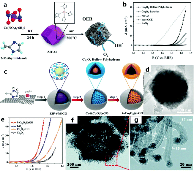 | ||
| Fig. 7 (a) Schematic diagram to illustrate the OER electrocatalytic principles of Co3O4 hollow polyhedra. (b) The polarization curve of the catalyst in 1 M KOH solution at a scanning speed of 2 mV s−1.56 Copyright © 2016 Wiley-VCH Verlag GmbH & Co. KGaA, Weinheim. (c) Schematic diagram of the preparation of the h-Co3O4@rGO hollow catalyst using ZIF-67@GO as a precursor. (d) TEM image of h-Co3O4@rGO. (e) The LSV curve of the catalyst at a scanning speed of 1 mV s−1.90 Copyright @ 2018, American Chemical Society. (f) TEM image of NCNHP-1-500. (g) CNTs in an enlarged TEM image of NCNHP-1-500.91 Copyright © 2019, Royal Society of Chemistry. | ||
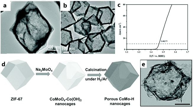 | ||
| Fig. 8 (a) TEM image of NiCo2O4/Co, N-CNTs NCs.92 Copyright @ 2018, American Chemical Society. (b) TEM image of precursor CoS. (c) LSV curve of CeOx/CoS/CC catalyst for the OER.47 Copyright © 2018 Wiley-VCH Verlag GmbH & Co. KGaA, Weinheim. (d) Schematic illustration describing the formation process of CoO–MoO2 nanocages. (e) TEM image of CoMo–H.93 Copyright © 2017 Wiley-VCH Verlag GmbH & Co. KGaA, Weinheim. | ||
Lyu and others93 prepared a CoO–MoO2 nanocage catalyst with excellent OER performance by refluxing the template (Fig. 8d and e). The CoMoO4–Co(OH)2 nanocage was prepared by the dissolution–regeneration method. The dissolution part involves etching ZIF-67 in the presence of water to release Co2+ ions. Na2MoO4 and Na2WO4 destroy the nanocage structure because dissolution is faster and regeneration is slower. However, in addition to providing an alkaline environment for the formation of Co(OH)2, Na2MoO4 can also provide MoO42−. Appropriate regeneration and dissolution rates can maintain the nanocage structure. As the reaction continues, the outward diffusion of Co2+ results in the formation of voids in CoMoO4–Co(OH)2. With the dissolution of the ZIF-67 core, a hollow CoMoO4–Co(OH)2 nanocage is finally formed, and the CoMoO4–Co(OH)2 nanocage is reduced to CoO–MoO2 during subsequent calcination under a reducing atmosphere.
For example, Li et al.96 used a convenient ion exchange method (i.e., an anion exchange reaction between the ZIF-67 crystal and Ni2+) to carefully synthesize a hollow (Co, Ni)Se2 nanocage from ZIF-67. More specifically, the formation of the nanocage involves a dissolution–regeneration process, and the entire diffusion process can be attributed to the Kirkendall effect.
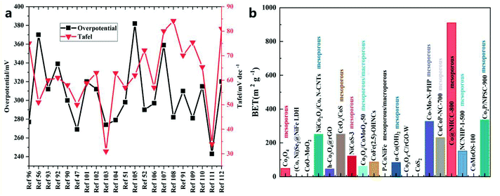 | ||
| Fig. 9 Comparison of (a) Tafel slope and overpotential at a current density of 10 mA cm−2 and (b) BET/BJH results for different catalysts. | ||
| HS | Substrate | Electrolyte | Overpotential/mV | Tafel/mV dec−1 | BET (m2 g−1)/BJH | Current density/mA cm−2 | Ref. |
|---|---|---|---|---|---|---|---|
| (Co, Ni) Se2@NiFe LDH | GC-RDE | 1 M KOH | 277 | 75 | — | 10 | 96 |
| Co3O4 | GCE | 1 M KOH | 370 | 51 | 49.27/mesoporous | 10 | 56 |
| CoO–MoO2 | GCE | 1 M KOH | 312 | 60 | — | 10 | 93 |
| NiCo2O4/Co, N-CNTs | GCE | 0.1 M KOH | 339 | 61 | 251/mesoporous | 10 | 92 |
| h-Co3O4@rGO | GCE | 1 M KOH | 300 | 58 | 46.5 | 10 | 90 |
| CeOx/CoS | GCE | 1 M KOH | 269 | 50 | 252.92/mesoporous | 10 | 47 |
| NiCoS-3 | GCE | 1 M KOH | 320 | 58.8 | 123/mesoporous | 10 | 101 |
| Co3O4/CoMoO4-50 | GC-RDE | 1 M KOH | 312 | 63 | 61.3/mesoporous/macroporous | 10 | 102 |
| CoFe(2.5)-OHNCs | GCE | 1 M KOH | 274 | 31 | 86.9 | 10 | 103 |
| P-CoNiFe | GCE | 1 M KOH | 279 | 62.9 | Mesoporous/macroporous | 10 | 104 |
| α-Co(OH)2 | GCE | 1 M KOH | 298 | 57 | 84.7/mesoporous | 10 | 51 |
| Co3O4–C/rGO-W | GCD | 0.1 M KOH | 382 | 62 | — | 10 | 105 |
| CoS2 | GCE | 1 M KOH | 290 | 72.2 | — | 10 | 52 |
| Co–Mo–N–PHP | GC-RDE | 1 M KOH | 297 | 57 | 328.5/mesoporous | 10 | 106 |
| CuCoP-NC-700 | GCE | 1 M KOH | 359 | 80 | 232/mesoporous | 10 | 107 |
| Co@NHCC-800 | GCE | 1 M KOH | 282 | 84.2 | 910.71/mesoporous | 10 | 108 |
| NCNHP-1-500 | GC-RDE | 1 M KOH | 310 | 70.1 | 152/mesoporous | 10 | 91 |
| CoMoOS-100 | GCE | 1 M KOH | 281 | 75.4 | — | 10 | 109 |
| Co2P/NPSC-900 | Carbon paper | 1 M KOH | 315 | 65.36 | 337.215/mesopores | 10 | 110 |
| ZIF-67@CoFe-PBA-F | GC | 1 M KOH | 243 | 34 | — | 10 | 111 |
| CoFe–Co@PNC-12 | GC | 0.1 M KOH | 320 | 81 | 564/micropores | 10 | 112 |
3.3 Array
The reasonable design of a nanoarray structure grown in situ can effectively improve the OER performance.113,114 In addition, catalysts using ZIF-67 arrays show excellent catalytic performance, but there are few studies in this field.As far as the OER based on the ZIF-67 framework is concerned, Jiang et al.115 chose nickel foam as the substrate for preparing CoO arrays (Fig. 10a and b). The CoO nanowire array is grown vertically on Ni foam and then selected as the precursor to provide the framework for the growth of Co2+ ions and ZIF-67 and dissolve its ligands with the help of a solvent. In addition, ZIF-67 nanorod arrays were successfully grown on Cu mesh, Fe mesh, and Cu foil by following similar synthesis steps. All these results demonstrate the universality of the current synthesis strategy for MOF-based hybrid arrays. The excellent electrocatalytic performance can be attributed to the more rapid release of air bubbles from the exposed active sites of the porous nanoarray. Unlike ZIF-67 grown in situ, Zhao et al.116 used an ion-exchange method to gradually convert 2D-ZIF-67 grown on carbon cloth to Co(OH)2, and then prepared the layered Fe LDH (FeCo)/Co(OH)2 array (Fig. 10c and d). The ion exchange method can replace the subsequent high-temperature carbonization process of MOFs to a certain extent. Yu et al.117 first synthesized vertically grown Cu(OH)2 nanorods on copper foam. Rod-shaped Cu(OH)2 is used as a template to obtain Cu(OH)2@ZIF-67 precursor on CF (Fig. 10e). After heat treatment, a layered CoO polyhedron-modified CuOx heterojunction nanorod array was obtained on CF. Benefiting from convenient electron transport between CuOx and CoO, CuOx@CoO NRs/CF showed considerable catalytic activity (Fig. 10f and g). Compared with the MnCo2O4@Co3O4 electrocatalyst prepared ex situ by Han and others,118 the catalyst prepared in situ showed a relatively good catalytic performance.
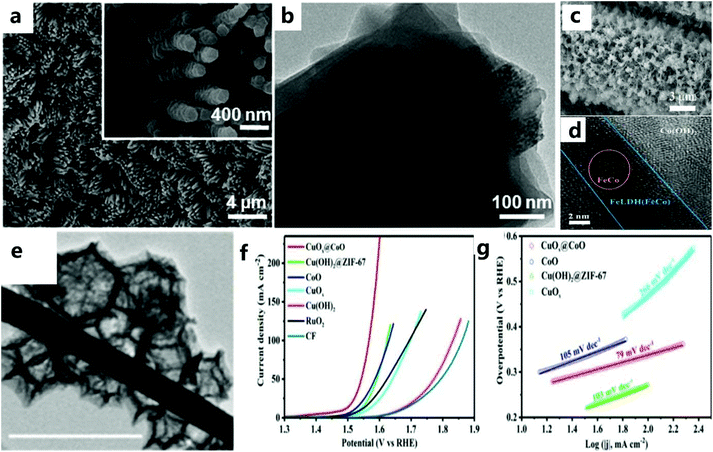 | ||
| Fig. 10 (a) SEM and (b) TEM images of as-prepared Ni@CoO@ZIF-67 arrays. Inset: enlarged SEM image.115 Copyright © 2017 Elsevier Inc. All rights reserved. (c) SEM image of FeLDH(FeCo)/Co(OH)2-2. (d) HRTEM image of Fe LDH(FeCo)/Co(OH)2-2.116 Copyright © 2019 Wiley-VCH Verlag GmbH & Co. KGaA, Weinheim. (e) TEM image of CuOx@CoO NRs. (f) LSV curve of the catalyst in 1.0 KM KOH and (g) the corresponding Tafel slope graph.117 Copyright © 2020 Wiley-VCH Verlag GmbH & Co. KGaA, Weinheim. | ||
The nanoarray architecture has a unique hierarchical structure, large surface area, a large number of active sites, convenient electron migration and mass transfer, close interface contact, and rapid bubble release, so it has excellent electrocatalytic activity and durability. Li et al.88 found through simulation calculations that the vertically arranged array structure could guide the uniform distribution of ion currents, so more catalytically active sites could be used more effectively, thereby promoting OER catalysis. It shows that the OER catalytic performance of the array structure has an outstanding performance (Table 4 and Fig. 11). Since the array structure can guide the uniform distribution of the ion current, it can use more catalytically active sites more effectively, so it exhibits better performance than other structures. Moreover, it still has an excellent catalytic performance at a high current density, and thus, is expected to be a catalyst for industrial production. Although great progress has been made in designing the structure of nanoarrays, enhancing the electrocatalytic performance is still a huge challenge, especially in ZIF-67 based catalysts. For effective and stable electrocatalytic water splitting, the catalytic performance of the catalyst can be improved by changing the composition, morphology, size, and interface of the catalyst and introducing dopants or defects. In addition, there is an urgent need to accurately prepare nanoarray structures on different conductive substrates.
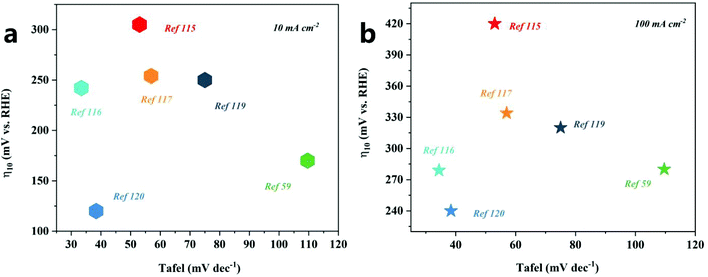 | ||
| Fig. 11 OER activity comparison graph showing the Tafel slopes versus overpotential at current densities of 10 mA cm−2 (a) and 100 mA cm−2 (b) for different catalysts. | ||
| Array | Substrate | Electrolyte | Overpotential/mV | Tafel/mV dec−1 | Current density/mA cm−2 | Ref. |
|---|---|---|---|---|---|---|
| Fe LDH(FeCo)/Co(OH)2 | CC | 1 M KOH | 242/279 | 34.4 | 10/100 | 116 |
| Co3O4@Ni2P–CoP/NF | NF | 1 M KOH | 250/298/320 | 75 | 10/50/100 | 119 |
| Ni@CoO@CoNC | NF | 1 M KOH | 309/420 | 53 | 10/100 | 115 |
| MnCo2O4@Co3O4 | NF | 2 M KOH | 170/280 | 109.6 | 10/100 | 59 |
| CuOx@CoO NRs/CF | NF | 1 M KOH | 254/334 | 56.9 | 10/100 | 117 |
| Co–Ni3S2/NF | NF | 1 M KOH | 120/240 | 38.4 | 10/100 | 120 |
4 Doping
The catalytic performance can be improved by carbonization at high temperature without destroying the structure of ZIF-67. In recent years, M–N–C materials have shown excellent performances in the application of electrochemical water splitting, and the presence of certain metals (such as Co) can promote the formation of structures such as CNTs. In addition, metal intercalation, N doping, and synergistic effects (adjustable H-bond energy and conductivity) all help to improve electrocatalytic performance.121–1234.1 Anion doping (AD)
The introduction of anions such as P, N, S, O or F with different atomic sizes and electronegativity into the matrix material will cause lattice distortion, thereby adjusting the electronic structure and catalytic activity. In addition, the synergistic effect between metal nanoparticles and heteroatoms also helps to improve electrocatalytic performance, and heteroatoms doped into the carbon framework can also help to activate π electrons by destroying the integrity of p-conjugation, thereby improving the electrocatalytic activity.124,125For example, Ni et al.51 designed a self-sacrificing template strategy, using the ZIF-67 dodecahedron and hexamethylenetetramine as reactants to synthesize hollow α-Co(OH)2 nano-dodecahedra. Experiments show that the prepared α-Co(OH)2 (hollow nano-dodecahedron) material has an excellent OER catalytic activity. In addition, under the same conditions, Cl-doped α-Co(OH)2 hollow nano-dodecahedra can also be prepared. The α-Co(OH)2 hollow nano-dodecahedron doped with Cl showed better OER activity. Catalysts doped with Cl atoms are easily etched under electrochemical conditions (Fig. 12a–c). Thus, introducing vacancies and defects improves the OER catalytic performance of α-Co(OH)2 hollow nano-dodecahedra. In addition, Zhang et al.126 prepared a Br-doped catalyst (BrHT@CoNC) through self-sacrifice and pyrolysis. Br doping will cause charge polarization, thereby promoting electron transfer, which will benefit OER catalysis. In addition, the defects introduced by Br doping are also beneficial to the catalytic process of the OER.
 | ||
| Fig. 12 (a) EDS analysis of Cl-doped α-Co(OH)2 catalyst in 1 M KOH solution. Cl 2p XPS spectra of the catalyst before OER test (b) and after the OER test (c).51 Copyright © 2019, Royal Society of Chemistry. | ||
Anion regulation, that is, modulating the electronic structure of the cation active site through the anion environment of the transition metal compound can effectively improve the catalytic activity of the catalyst. Precise anion regulation is expected to construct an ideal anion structure, thus presenting the best intrinsic catalytic activity. However, precise anion control is still very difficult, and new anion control strategies need to be developed.127,128
4.2 Cation doping (CD)
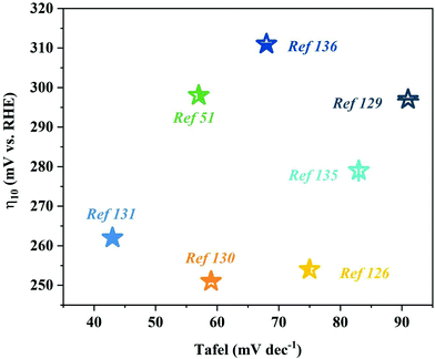
To optimize the local electronic environment and increase the catalytic activity, the introduction of anion vacancies can lead to the formation of high-energy dangling bonds and low coordination sites, thereby promoting OER catalytic reactions. In addition, CD is also a way to improve conductivity and reduce the binding energy of intermediate products, and it can be found that the d-band doping of transition metal elements can also effectively improve the catalytic performance of the OER. That is, the doping of transition metal elements improves the catalytic process of the OER by adjusting the electronic structure, adjusting the redistribution of charges, and so on. For example, Liu et al.129 have reported a new type of OER catalyst: Fe-Co1.11Te2@NCNTF (NCNTF: nitrogen-doped carbon nanotube framework). The catalyst is synthesized by tellurizing the catalyst obtained after Fe3+ etching of ZIF-67 in H2/Ar gas. The improved electrocatalyst (Fe-Co1.11Te2@NCNTF-2) shows excellent OER catalytic performance (107 mV@10 mA cm−2) in 1M KOH. However, undoped Fe Co1.11Te2@NCNTF showed an overpotential of 165 mV, which indicated that Fe doping could adjust the electronic structure of the catalyst and promote the OER reaction kinetics, thereby improving the catalytic performance (Fig. 13a and b).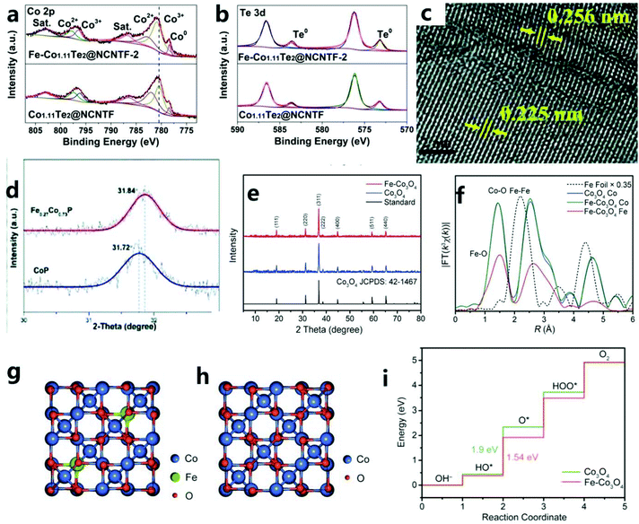 | ||
| Fig. 13 Comparison of the XPS spectra of (a) Co 2p and (b) Te 3d in Co1.11Te2@NCNTF and Fe-Co1.11Te2@NCNTF-2.129 Copyright © 2020 Wiley-VCH GmbH. (c) HRTEM image of Fe0.27Co0.73P. (d) XRD patterns for slow scanning at one degree per minute. (e) XRD patterns of Co3O4 HHNPs and Fe–Co3O4 HHNPs together with the standard pattern of Co3O4.130 Copyright © 2019, Royal Society of Chemistry. (f) FT of EXAFS k3χ(k) spectra of Fe–Co3O4 with Fe foil and Co3O4 as references. (g) The optimized Fe–Co3O4 structure for calculation. (h) Crystal structure of Co3O4. (i) Free energy diagram for the OER process over Co sites.131 Copyright © 2020 The Authors. Published by Wiley-VCH Verlag GmbH & Co. KGaA, Weinheim. | ||
Mu et al.130 proposed a simple and practical method based on a metal–organic framework to prepare iron-doped cobalt phosphide (Fe0.27Co0.73P). Through Fe doping, the obtained electrocatalyst (Fe0.27Co0.73P/NF) coated on Ni foam substrate has an excellent OER performance (η10 = 251 mV). In addition, when Fe0.27Co0.73P/NF is used as a symmetric electrode in 1.0 M KOH alkaline solution, it also has an excellent OER catalytic performance (1.68 V@10 mA cm−2). In addition, a small amount of iron that failed to enter the cobalt phosphide lattice is phosphated (Fig. 13c and d). This phosphated iron facilitates the redistribution of charges, thereby promoting the OER performance of the electrocatalyst. In addition, Lou et al.131 prepared a layered cross-channel hollow NP composed of ultra-thin Co3O4 nanosheets by an etching–coordination–recombination method. The advantage of this method is also that it permits the simultaneous introduction of a second metal. In general, metal elements can be doped into ultra-thin Co3O4 nanosheets in the form of isolated metal sites (Fig. 13e and f). For example, doping with Fe atoms at the octahedral site of Co3O4 greatly enhances the intrinsic electrical activity of the catalyst, and all doped Fe atoms should exist near the surface. Therefore, it is easy to understand that, as shown by the DFT results, even a small amount of Fe atom doping will greatly enhance the electrocatalytic activity (Fig. 13g–i).
It is certain that the incorporation of iron plays an important role in improving OER catalysis. However, the enhancement of the electrocatalytic activity by single metal doping is still limited. In addition, the electronic structure and the adsorption of intermediates can be optimized due to doping with various metal ions. Therefore, the combined doping with multiple metal ions will be a promising method for water splitting.132 Studies have shown that the simultaneous incorporation of two foreign cations can more effectively adjust the lattice structure and electronic interaction, thereby further improving the catalytic performance.133
4.3 Co-doping (CoD)
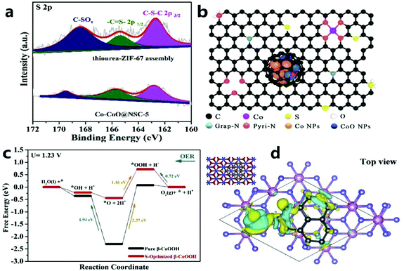 | ||
| Fig. 14 (a) S 2p XPS spectrum of thiourea–ZIF-67 component and Co–CoO@NSC-5. (b) Microscopic diagram of Co–CoO@NSC-5. (c) The calculated free-energy diagram of the OER on S-optimized β-CoOOH (001) (U = 1.23 V). (d) The spin charge density distribution of β-CoOOH (001) (top view). Yellow indicates spin up and cyan indicates spin down.135 Copyright © 2020 Elsevier B.V. All rights reserved. | ||
Jin et al.136 used H3PO4 to selectively etch ZIF-67 to synthesize a P/N co-doped carbon catalyst material (Co/P/N–CNP) with micro/mesomicropores. H3PO4 not only effectively controls the porosity of ZIF through etching, but also is an ideal phosphorus source for P doping, which effectively improves the performance of the catalyst. The Co/P/N–CNP catalyst obtained after pyrolysis is modified with multi-walled carbon nanotubes and has both micropores and mesopores, which are beneficial for exposing more reactive sites during OER electrocatalysis.
In the anion adjustment process, some of the original anions are replaced with foreign anions to obtain polyanionic compounds. The obtained polyanionic compound has a heteroatom structure, polarized and non-polarized anions with atom distribution. The dispersed electrons of the polarized anion are shared with adjacent cations, thereby adjusting the covalent and ionicity of the interaction between the cation and anion. Non-polarized anions are mainly ionic, with weak electronic interaction. The polarized sulfur anion and the non-polarized oxyanion coordinately adjust the electronic structure of the active site through the electronic interaction with the cation. Through anion adjustment, the degree of polarization of the cation active site can be fully adjusted through the heteroatom structure, thereby generating a favorable electronic structure for effective electrocatalysis. In addition, the CoD strategy for cations and anions is very attractive because it may cause a double synergistic effect in adjusting the electronic structure and changing the adsorption energy during the reaction to promote the catalytic performance. In addition, we compared the catalytic performance of different ion-doped catalysts (Fig. 15). Many nanostructures benefit from the structural tunability and synergistic effects of dopants. Therefore, in addition to studying structure regulation and doping separately, we should also explore the synergistic effects between them to combine their respective advantages for improved catalyst performance.
5 ZIF-67 derived single atom catalyst
The special structure of a MOF can be transformed into a single-atom electrocatalyst with high activity and the M–Nx–C structure by improving the physical design of a MOF to increase the catalytic efficiency of water oxidation. Inspired by the ultra-high utilization of single atom catalysts (SAC), MNC catalysts with atomic dispersion (especially from MOFs) are currently the focus of attention from researchers. Therefore, the design of the original MOF single-atom electrocatalyst is essential. For example, Wang et al.137 stabilized metal ions (Pt2+/Ir2+/Pd2+/Ru2+/Ni2+/Fe2+) by coordinating them with the π electron of the imidazole group of ZIF-67, thereby anchoring an isolated single-atom on the imidazole group of ZIF-67, to obtain a catalyst composed of N-doped carbon matrix and metal nanoparticles through a simple pyrolysis process. Then, through experiments and DFT calculations, it can be found that the high accessibility of the numerous tunnels in the ZIF-67 framework disperses individual atoms, thereby greatly increasing the density of active sites.In addition, Wang et al.138 used plasma etching (DBDPT) to remove the partial distribution of ZIF-67 and generate coordinatively unsaturated metal sites (CUMS) for electrochemical catalysis. By adjusting the geometric ligands to produce CUMS, Co ions are converted into active catalytic centers (Fig. 16a). In addition, CUMS formed by plasma etching can be used to remove organic ligands for OER catalysis. The specific structure of the catalyst and monodisperse CUMS after etching lead to an excellent OER catalytic performance (Fig. 16b). DFT calculations confirmed that the unsaturation of the catalyst after etching could effectively improve the activity of the catalyst (Fig. 16c). In addition to the method of etching the ligand, Dilpazir et al.139 used dicyandiamide modification to prepare CoSAs@NCNT single-atom catalysts (Fig. 16d–g). This catalyst with Co atom-immobilized CNTs exhibits excellent OER performance. Combining melamine with a carbon matrix promotes the formation of carbon nanotubes, and the formation rate of carbon nanotubes is controlled by the autocatalysis of cobalt nanoparticles (Fig. 16h). In addition, it can also be found that the nitrogen-rich DCD is responsible for the generation of stable Co single-atom sites. Nitrogen in the DCD surrounds the Co site, thus limiting the formation of aggregated nanoparticles. Recently, Sun and others140 prepared a single Co atom catalyst (UNT Co SAs/NC) (Fig. 16i and j) with a urchin-like hierarchical structures and a precise arrangement through a simple MOF template method. The prepared catalyst has an excellent catalytic performance due to its unique single-atom characteristics (Fig. 16k). In addition, the consistency between DFT calculations and experiments shows that UNT Co SA/NC with CoN4 can effectively improve the performance of OER catalysts (Fig. 16l).
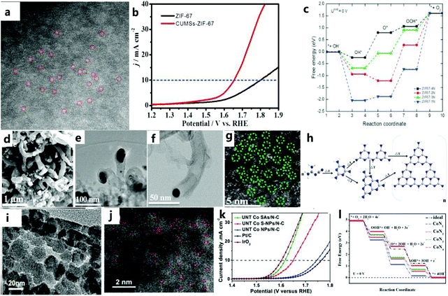 | ||
| Fig. 16 (a) Corresponding SAED pattern of CUMS-ZIF-67. (b) LSV polarization curves of ZIF-67 and CUMS-ZIF-67 electrocatalysts. (c) Free energy diagrams of ZIF-67-xN (x = 1–4).138 Copyright © 2017 Elsevier Ltd. All rights reserved. (d) SEM image of CoSAs@CNTs. (e) TEM image of CoSAs@CNTs. (f) HAADF image of CoSAs@CNTs. (g) HAADF image showing the atomic distribution of cobalt atoms. (h) Schematic illustration of the growth mechanism of CNTs.139 Copyright @ 2018, American Chemical Society. (i) TEM image of hierarchical UNT Co SAs/N–C catalyst. (j) HAADF-STEM image of hierarchical UNT Co SAs/N–C catalyst. (k) OER polarization curve of the catalyst. (l) Free-energy diagrams for OER pathways in an alkaline medium on CoNx (x = 1–4) active sites.140 Copyright © 2019 Elsevier Ltd. All rights reserved. | ||
In short, ZIF-67 has unique π electrons in the imidazole pentagon, which can be used as an aggregation inhibitor, and the unique coordination environment facilitates the preparation of single-atom catalysts.
6 Compound catalyst of ZIF-67 derivatives
Compared with the original ZIF-67 material, the ZIF-67 derived composite catalyst maintains the advantages of ZIF-67's high specific surface area and large porosity, which can provide more active sites for the catalytic process, and after carbonization and various subsequent treatments, the electron transport efficiency of the catalyst is improved, thereby improving its catalytic performance. Besides pristine ZIF-67 and their derived porous carbons, ZIF-67 can also be converted into metal oxides, metal phosphides, chalcogenides, etc. under certain conditions. The special combination of the metal center and organic complex in ZIF and its heat treatment, as well as the feasible introduction of the second precursor, will introduce more active sites to improve the performance of the catalyst. In addition, due to some shortcomings of ZIF-67 and its derivatives, the OER catalytic performance is limited. We can make up for these shortcomings by doping and compounding to improve the catalytic performance. This synergistic effect improves the catalytic performance through a similar synergistic chemical coupling effect.1416.1 ZIF-67 derived transition metal oxide catalyst (ZDMOC)
As a low-cost alternative, a composite of transition metal oxide and carbon materials shows catalytic activity for the OER.142 Generally, a transition metal oxide is considered to be the main catalyst for the OER.143 The MOF is a type of porous material assembled from metal ions and organic linkers and has become the main focus of nanoscience.144,145 In particular, MOFs can be used as a self-sacrificing template to prepare porous transition metal oxide or metal/N-doped carbon materials. Due to the unique structure of the MOF, the derived material has a large surface area and a layered porous structure, which are necessary for the high-performance OER process.146,147For example, Luo et al.148 prepared catalysts with different structures (Co3O4/NPC) by controlling the pyrolysis of different ZIF-67 precursors (Fig. 17a–c). Catalysts with different structures exhibit different catalytic performances. In addition, due to the large number of defects in the amorphous catalyst, this can provide a larger number of OER active sites compared with the crystalline catalyst. For example, Pang et al.149 prepared catalysts with different crystalline morphologies by heat-treating ZIF-67 hollow spheres by controlling the temperature (Fig. 17d). Through electrochemical testing, it can be found that the catalytic activity of the amorphous Co3O4 catalyst is better than that of the crystalline catalyst (Fig. 17e).
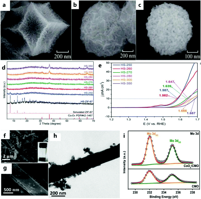 | ||
| Fig. 17 (a) SEM images of T-Co3O4/NPC, (b) M-Co3O4/NPC, (c) and H-Co3O4/NPC.148 Copyright @ 2017,The Author(s). (d) XRD patterns of all samples. (e) LSV curves of HS-250, HS-260, HS-270, HS-280, HS-300, and HS-350.149 Copyright © 2019 Wiley-VCH Verlag GmbH & Co. KGaA, Weinheim. (f and g) TEM images of CoOx/CMO. Inset is a picture of the as-prepared sample. (h) TEM image of CoOx/CMO. (i) High-resolution Mo 3d XPS spectra of CoOx/CMO-p and CoOx/CMO.45 Copyright © 2019 Elsevier B.V. All rights reserved. | ||
In addition, designing multiple composites of M–Co compounds further improves the catalytic performance.102,150 Recently, studies have shown that Mo can effectively cooperate with Co, and has led to great progress in this field.151 For example, Chen et al.45 prepared a catalyst with a special structure of nanorods and nanoparticles (Fig. 17f–h). The cooperative interaction between CMO nanorods and CoOx nanoparticles can achieve efficient charge transfer and promote electrocatalytic OER processes (Fig. 17i).
6.2 ZIF-67-derived transition metal phosphide catalyst (ZDMPC)
In recent years, due to the attractive performance of nanostructured metal phosphides in electrocatalytic applications, extensive research has been conducted on them. Metal phosphides are a type of electrocatalyst used in the OER.152–154 Although some progress has been made, the OER performance of metal phosphides still needs to be improved. For example, Li et al.155 successfully prepared the CoNiP/NC catalyst (Fig. 18a and b) as an effective electrocatalyst for the OER using the common method of phosphating (i.e., annealing NaH2PO2 and catalytic materials under an inert atmosphere). Among the electrocatalysts obtained by controlling the carbonization and phosphating temperature, the CoNiP/NC700 catalyst (where 700 represents the calcination temperature (°C)) exhibits excellent electrocatalytic activity for the OER. In addition, the CoNiP/NC electrocatalyst obtained at 700 °C has a superior OER catalytic performance to those of Co/NC and CoNi/NC (Fig. 18c). Among them, the better electrocatalytic activity of hybrid materials can be attributed to the strong electronic coupling effect of Co, Ni, P, and C. In addition to the above-mentioned commonly used method of phosphating, Jin et al.136 also selectively corroded the ZIF-67 precursor with H3PO4, and then pyrolyzed it to obtain the Co/P/N–CNP catalyst (Fig. 18d and e). This method not only effectively controls the porosity of ZIF, but can also effectively dope P into the carbon matrix. P greatly enriches the electrocatalytically active sites of the obtained carbon catalyst.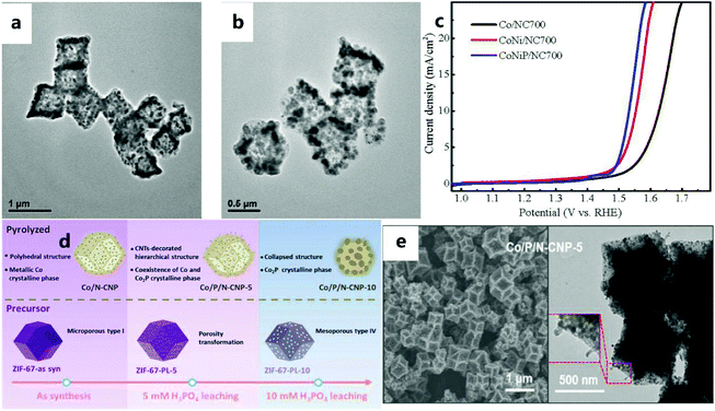 | ||
| Fig. 18 (a) TEM images of CoNi/NC700 and (b) CoNiP/NC700. (c) Polarization curves in KOH solution.155 Copyright © 2018 Dalian Institute of Chemical Physics, the Chinese Academy of Sciences. Published by Elsevier B.V. All rights reserved. (d) Schematic illustration of a pre-leaching strategy for the preparation of Co/P/N–CNP catalysts. (e) SEM and TEM images of Co/P/N-CNP-5.136 Copyright © 2020 Elsevier Ltd. All rights reserved. | ||
6.3 ZIF-67-derived transition metal sulfide catalyst (ZDMSC)
Transition metal sulfides are widely studied as promising electrocatalysts due to their high abundance, low cost, and excellent electrocatalytic activity.156–158 In recent years, due to abundant raw materials, environmental protection characteristics, and excellent performance of MOF derivatives, they have received extensive attention from researchers.159,160 Studies have shown that the effect of S on metal active sites for the OER is similar to that of P.161 Therefore, in recent years, people have used the ZDMSC catalyst for OER electrocatalysis. In addition, there is a synergy between the nanoscale interfaces of different transition metal catalysts, which will further enrich structural defects and stimulate some inert sites, thereby increasing the activity of the two transition metal catalysts. For example, Yang and others162 first introduced the preparation of Co–Ni–S co-doped N-enriched (CoNixSy/NCP) through an absorption–pyrolysis–sulfurization method (Fig. 19a and b), and it can be seen that the performance of the catalyst after vulcanization has been significantly increased (Fig. 19c). Compared with pyrolysis vulcanization, Zhang et al.163 used a more convenient and energy-saving ion exchange method to prepare amorphous CoSx@C, that is, amorphous CoSx@C was calcined under Ar at 400 °C to obtain Co1−xS@C. The Co1−xS@C catalyst (Fig. 19d) showed an effective OER activity (Fig. 19e). The excellent electrical conductivity of Co1−xS@C (Fig. 19f), the porous structure that promotes mass transfer, and the uniform dispersion of Co1−xS@C particles throughout the carbon skeleton lead to an excellent catalytic performance.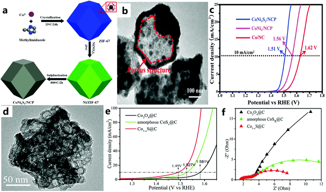 | ||
| Fig. 19 (a) Schematic diagram for the fabrication of CoNixSy/NCP. (b) TEM image of CoNixSy/NCP. (c) Polarization curves of Co/NC, CoNix/NCP, and CoNixSy/NCP in 1 M KOH solution (scan rate: 10 mV s−1).162 Copyright © 2019 Hydrogen Energy Publications LLC. Published by Elsevier Ltd. All rights reserved. (d) TEM image of Co1−xS@C. (e) LSV polarization curves of Co3O4@C, Co1−xS@C, and amorphous CoSx@C. (f) EIS Nyquist plots of Co3O4@C, Co1−xS@C, and amorphous CoSx@C.163 Copyright © 2018 Published by Elsevier B.V. on behalf of Chinese Chemical Society and Institute of Materia Medica, Chinese Academy of Medical Sciences. | ||
6.4 ZIF-67-derived transition metal selenide catalysts (ZDMSeC)
Both selenium and transition metals have d orbitals, and the 3d–2p repulsion between them results in faster delivery of dioxygen intermediates, thereby increasing the OER activity.161 For example, Tian et al.49 used a convenient hydrothermal method to construct high-performance nanovesicle CoSe2 electrode materials. Then, by adjusting the stoichiometric ratio of Co and Se, they studied the nanovesicle CoSe2 in detail. It can be found that the best CoSe2-30 catalyst (Fig. 20a) has an excellent OER performance. Fig. 20b illustrates the presence of Co2+ and Co3+, and Fig. 20c demonstrates the formation of cobalt selenide on the surface of the electrocatalyst. It can be seen that selenium and cobalt do interact. Wei et al.164 prepared Ni–Co–Se dodecahedral nanocage catalysts by selenization (Fig. 20d), and the synergistic combination of Co0.85Se and Ni0.85Se in the nanocage may help to improve the catalytic activity. Similarly, Fig. 20e and f demonstrate the formation of cobalt selenide on the surface of the electrocatalyst. The abovementioned results all indicate that the yolk–shell Ni–Co–Se nanocage/CFP electrode has an excellent electrocatalytic performance under alkaline conditions.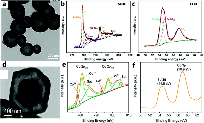 | ||
| Fig. 20 (a) TEM image of CoSe2-30. (b) Co 2p and (c) Se 3d XPS spectra of CoSe2-30.49 Copyright © 2019 Elsevier B.V. All rights reserved. (d) HR-TEM image of Y–S Ni–Co–Se. XPS spectra of the (e) Co 2p and (f) Se 3d regions.164 Copyright @ 2018, American Chemical Society. | ||
6.5 ZIF-67-derived transition metal telluride catalyst (ZDMTC)
Because tellurium is very similar to sulfur and selenium, it is extremely valuable to study the role of tellurium in catalysis. For example, Wang et al.165 encapsulated CoTe2 in a nitrogen-doped carbon nanotube framework (called CoTe2@NCNTFs) through a tellurization process under a hydrogen atmosphere (Fig. 21a and b). ZIF-67 converts its organic ligands into a nitrogen-doped carbon nanotube framework (NCNTF) through pyrolysis, and the central metal cobalt atom forms ultrafine CoTe2 nanoparticles in situ (Fig. 21c), so the combination of CoTe2 and NCNTF leads to high stability and strong interactions. This nitrogen-doped carbon nanotube framework of ZIF-derived material can effectively increase the active sites and specific surface area of the catalyst (Fig. 21d), thereby improving the catalytic performance of the OER. When the prepared CoTe2@NCNTF catalyst has a current density of 10 mA cm−2 in an alkaline solution (1.0 M KOH), it exhibits a high electrocatalytic performance with a high potential of 330 mV for the OER (Fig. 21e and f).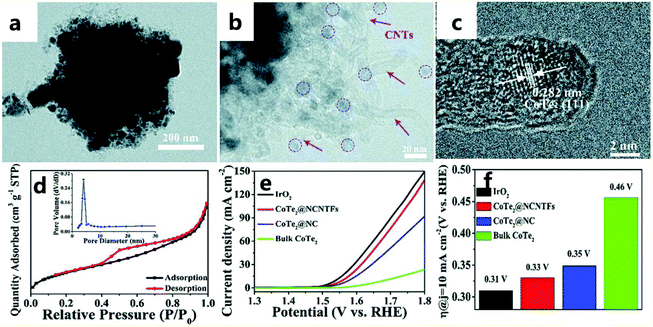 | ||
| Fig. 21 (a and b) TEM images of CoTe2@NCNTFs. (c) HRTEM image of CoTe2@NCNTFs. (d) N2 adsorption–desorption isotherms and the corresponding pore size distribution (inset) of CoTe2@NCNTFs. (e) CoTe2 polarization curves of different catalysts. (f) Histogram of the overpotential of different catalysts at 10 mA cm−2.165 Copyright © 2018, Royal Society of Chemistry. | ||
6.6 Summary
ZIF-67 can be converted into metal oxides, metal phosphides, and chalcogenides (sulfides and selenides), which show excellent OER performance (Fig. 22 and Table 5). It can be found that the overall overpotential of the vulcanized catalyst is better than that of other catalysts, and the overpotential distribution has a tendency of vulcanization > phosphating > selenization > oxidation. However, the Tafel slope after vulcanization is larger, which indicates that the rate-determining step is not at the end of the multi-electron transfer reaction. The reasonably designed ZIF-67 can also be evolved into an electrocatalyst containing highly active M–Nx–C, which is used to improve the catalytic efficiency of water oxidation. The special combination of the metal center and the organic complex and its heat treatment, as well as the feasible introduction of a second precursor, are used to improve the efficiency of the electrocatalyst. Finally, a more in-depth understanding should be obtained and theoretical research should be conducted on the synergistic effect between the metal of the metal derivative and the carbon support, the doping effect of foreign atoms, and the phase transition in the electrochemical evolution of the ZIF-derived metal electrocatalyst. This is an indication that ZIF-67 and its derivatives are promising for the development of OER catalysts.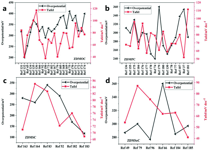 | ||
| Fig. 22 Comparison of the Tafel slopes and the overpotentials of different catalysts of (a) ZDMOC, (b) ZDMPC, (c) ZDMSC and (d) ZDMSeC at a current density of 10 mA cm−−2. | ||
| ZDMOC | Substrate | Electrolyte | Overpotential/mV | Tafel/mV dec−1 | Current density/mA cm−2 | Ref. |
|---|---|---|---|---|---|---|
| M-Co3O4/NPC | GCE | 1 M KOH | 317 | 84 | 10 | 131 |
| Co3O4/N-CNTs | GCE | 1 M KOH | 200 | 40 | 10 | 132 |
| CoOx/CMO | RDE | 1 M KOH | 253 | 75.8 | 10 | 45 |
| CoMoO4 | GCE | 1 M KOH | 315 | 89 | 10 | 134 |
| Co3O4-CNTs | GCE | 0.1 M KOH | 370 | 100 | 10 | 135 |
| HS-260 | GCE | 1 M KOH | 352 | 117 | 10 | 136 |
| CO/NCO/NF | NF | 0.1 M KOH | 320 | 68 | 10 | 166 |
| NiCo2O4/Co,N-CNTs NCs | GC-RDE | 0.1 M KOH | 339 | 61 | 10 | 92 |
| Co3O4−x-carbon@Fe2−yCoyO3 | GCE | 1 M KOH | 290 | 37.6 | 10 | 150 |
| Co3O4/HNCP-40 | GCE | 1 M KOH | 333 | 69 | 10 | 73 |
| Co3O4/CoMoO4-50 | GC-RDE | 1 M KOH | 318 | 63 | 10 | 102 |
| Co3O4/NPC-2 | GCE | 1 M KOH | 330 | 79 | 10 | 167 |
| Co-BO@Co3O4 | GCE | 1 M KOH | 350 | 40.3 | 10 | 79 |
| Co3O4-C/rGO-W | GCD | 0.1 M KOH | 382 | 62 | 10 | 105 |
| Co/CoOx@NC-CNTs | RRDE | 0.1 M KOH | 390 | 80 | 10 | 168 |
| CuOx@CoO NRs/CF | CF | 1 M KOH | 334 | 79 | 100 | 169 |
| Co@Co3O4/NC-2 | GCE | 0.1 M KOH | 410 | 54.3 | 10 | 75 |
| Ce(3)–Co3O4 | GCE | 1 M KOH | 369 | 56 | 10 | 170 |
| ZIF-67-CNT | GCE | 1 M KOH | 390 | 95.7 | 10 | 171 |
| Co@NC-G-700 | GCE | 1 M KOH | 322 | 73.7 | 10 | 172 |
| MoO2–Co2Mo3O8@C | GCE | 1 M KOH | 320 | 88 | 10 | 173 |
| NixCoyO4/Co-NG | RDE | 0.1 M KOH | 399 | 77.2 | 10 | 174 |
| ZDMPC | Substrate | Electrolyte | OER/mV | Tafel/mV dec−1 | Current density/mA cm−2 | Ref. |
| Co/P/N-CNP-5 | NF | 1 M KOH | 311 | 67.7 | 10 | 136 |
| CoNiP/NC700 | GCE | 1 M KOH | 300 | 66 | 10 | 155 |
| NiCoP/C | GCE | 1 M KOH | 330 | 96 | 10 | 175 |
| P–CoNiFe | GCE | 1 M KOH | 279 | 62.9 | 10 | 104 |
| NiCoPO/NC | GCE | 1 M KOH | 300 | 94 | 10 | 176 |
| CNTs@NiCoP/C | GCE | 1 M KOH | 297 | 57.35 | 10 | 177 |
| CNT-NC-CoP | GCE | 1 M KOH | 251 | 82.1 | 10 | 178 |
| Co-NC@CoP-NC | GCE | 0.1 M KOH | 240 | 79 | 10 | 74 |
| Co–P/NC/CC | CC | 1 M KOH | 360 | 61 | 10 | 179 |
| CoP-InNC@CNT | GCE | 1 M KOH | 270 | 84 | 10 | 180 |
| Fe0.27Co0.73P/NF | NF | 1 M KOH | 251 | 59.1 | 10 | 130 |
| NiCoP/C@FeOOH | GCE | 1 M KOH | 271 | 69 | 10 | 78 |
| CoP/CN@MoS2 | GC-RDE | 1 M KOH | 289 | 69 | 10 | 77 |
| CuCoP-NC-700 | GCE | 1 M KOH | 338 | 80 | 10 | 107 |
| Co–P/NC | RDE | 1 M KOH | 354 | 52 | 10 | 37 |
| CoP/NC-800 | GCE | 1 M KOH | 290 | 111.4 | 10 | 181 |
| ZDMSC | Substrate | Electrolyte | OER/mV | Tafel/mV dec−1 | Current density/mA cm−2 | Ref. |
| CoNixSy | GCE | 1 M KOH | 280 | 71 | 10 | 163 |
| Co1−xS@C | platinum wire | 1 M KOH | 260 | 85 | 10 | 164 |
| Co9S8@Co9S8@MoS2-0.5 | GCE | 1 M KOH | 340 | 82.7 | 10 | 83 |
| CoS2NBs-12 | GCE | 1 M KOH | 290 | 72.2 | 10 | 52 |
| NCO@CoS | NCO@CoS | 1 M KOH | 170 | 76 | 10 | 182 |
| Mo,Co-NiS/NF-400 | NF | 1 M KOH | 117.2/200 | 68.9 | 10/100 | 183 |
| ZDMSeC | Substrate | Electrolyte | OER/mV | Tafel/mV dec−1 | Current density/mA cm−2 | Ref. |
| CoSe2-30 | GCE | 1 M KOH | 287 | 54.3 | 10 | 49 |
| Y–S Ni–Co–Se | CFP | 1 M KOH | 300 | 87 | 10 | 79 |
| (Co,Ni)Se2@NiFe | GC-RDE | 1 M KOH | 277 | 75 | 10 | 96 |
| ZIF-Co0.85Se | GC-RDE | 1 M KOH | 360 | 62 | 10 | 66 |
| CC/CNTs@CoS0.74Se0.52 | CC | 1 M KOH | 285 | 63 | 10 | 184 |
| CoSe2/CF | CF | 1 M KOH | 297 | 41 | 10 | 185 |
7 Mechanistic analysis
7.1 The catalytic activity of ZIF-67 and its favorable adsorption sites
When seeking a high-efficiency oxygen evolution electrocatalyst based on ZIF-67 materials and their derivatives, basic theoretical calculations have always played an important role in rationally designing and analyzing the performance of electrocatalysts for OER reactions. To understand the OER reaction mechanism, basic theoretical calculations based on first-principles density functional theory (DFT) have become “standard tools” for analyzing basic reaction steps.186 For example, for the catalysis of ZIF-67, Wang et al.138 used DFT methods to perform first-principles calculations to determine the electronic structure and catalytic activity of saturated and unsaturated ZIF-67. For saturated ZIF-67, the rate-limiting step in the basic reaction is the second electron transfer, and for the unsaturated reaction (x = 2–3), this is the third step of electron transfer. As shown in Fig. 23a, the top of the volcano diagram is the overpotential of the best catalyst, which is consistent with the experimental results. In addition, the Sabatier principle states that the interaction between the catalyst and the adsorbent should be moderate (not too strong or too weak). However, the amount of ligand will strongly affect the adsorption energy of the catalyst, so the amount of ligand will have a greater impact on the electrocatalytic performance of the OER. In addition, they found that the change in the charge on the metal site changes with the change in the number of ligands. The role of the ligand is closely related to the redistribution of the charge on the active site. For a metal, because it has a positive charge, it will have a strong interaction with oxygen, which is conducive to the adsorption of O2, O, OH, OOH, and will become the active center for the OER.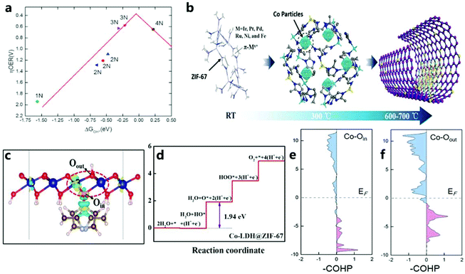 | ||
| Fig. 23 (a) ZIF-67-xN (x = 1–4) volcano diagram related to the OER catalytic activity and OH adsorption energy on the Co site.138 Copyright © 2017 Elsevier Ltd. All rights reserved. (b) Illustration of locations of metal cations and π electrons. (At room temperature, metal cations are initially related to π electrons. At 300 °C, the metal atoms embedded in cobalt form single atoms. At 600–700 °C, cobalt forms on the base carbon atom.)137 Copyright © 2019 Wiley-VCH Verlag GmbH & Co. KGaA, Weinheim. (c) The charge density difference of the underlying layer for Co-LDH@ZIF-67, and (d) the Gibbs free energy step diagram of the OER on Co-LDH@ZIF-67. pCOHP for (e) Co–Oin and (f) Co–Oout in Co-LDH@ZIF-67.187 Copyright © 2020 The Authors. Published by Wiley-VCH GmbH. | ||
In addition, Wang et al.137 used DFT calculations to show the sites (N, Co, and C) on ZIF-67 that were conducive to metal adsorption. Metal adsorption demonstrated includes that of Pt, Pd, Ir, Ru, Fe, and Ni (Fig. 23b). It should be noted that, since the electronegativity of N is higher than that of C, more polarized electrons will be attracted to N atoms, but the deformed charge density also shows that the existence of C–C bonds and C–N bonds can redistribute the charges of all atoms in this structure. Li et al.187 performed DFT calculations on Co-LDH@ZIF-67 to reveal the origin of the interface effect in the OER (Fig. 23c and d). To study the internal mechanism of electron transfer and Co–O bond strength in the catalyst (Co-LDH@ZIF-67) in depth, they calculated the projection crystal Hamiltonian (pCOHP) to illustrate the interaction of Co–Oin and Co–Oout (Fig. 23e and f). In addition, the decrease in free energy during the OER is due to the interaction between ZIF-67 and Co-LDH, and the decrease in antibonding orbital filling of the Co–O bond is due to the strong electron attraction of the ligand.
7.2 Catalysis of ZIF-67 derivatives
To further analyze the influence of the adsorption capacity of the intermediate on inherent catalytic activity of the catalyst, Wu et al.188 performed DFT calculations on the free energy of intermediate adsorption and the charge density redistribution of C, Co@C, and Co@N1C31. First, the Co@C model is doped with nitrogen to generate an n-type doped C layer. After doping, the charge density of the Co@C–OOH system will be rebalanced, thereby further enhancing the bonding strength of C–OOH (Fig. 24a). It can be found that N-doped Co–C conjugated species can effectively change the catalytic activity of the OER. Wang et al.167 calculated the geometric and electronic effects of Co3O4/NPC on the activation and adsorption/desorption of reactive species through DFT theory. As shown in Fig. 24b, the most stable structure of Co3O4/NPC exhibits the cubic configuration of Co4O8. It can be found that H2O is preferentially adsorbed on Co3O4 instead of on the NPC carrier. At the same time, weakly adsorbed O2 is easy to desorb from the loaded Co3O4 nanoparticles. As shown in the PDOS of Fig. 24c, it can be found that spin polarization on the surface of the catalyst is stronger. Secondly, most of the Co 3d states are located at the Fermi level and overlap with the N 2p state, which just shows that the unsaturated Co and N atoms have a synergistic effect on the OER process. Generally, the excellent OER catalytic performance is due to the special geometric and electronic effects of Co3O4/NPC on the reactive species, as well as activation and adsorption/desorption.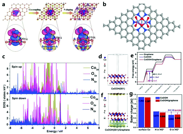 | ||
| Fig. 24 (a) Redistribution of charge density in C–OOH, Co@C–OOH and Co@N1C31–OOH systems.188 Copyright © 2019 Wiley-VCH Verlag GmbH & Co. KGaA, Weinheim. (b) Structure of Co3O4/NPC from the top view. (c) Partial density of states of surface Co ions, O atoms and N atoms of NPC in Co3O4/NPC.167 Copyright © 2017 Elsevier B.V. All rights reserved. (d) Side view of the three-dimensional charge density difference graph of CoOOH(001). (e) Gibbs free energy step diagram of the OER on various catalysts. (f) Side view of the three-dimensional charge density difference graph of CoOOH(001)/graphene. (g) Bader charge analysis of the surface Co ions and H or O in the adsorption of HO* on the surface of CoOOH and CoOOH/graphene.178 Copyright © 2018 Elsevier Ltd. All rights reserved. | ||
In addition, Huang et al.178 used the (001) surface of CoOOH and single-layer pure graphene of the N-doped graphitic carbon layer for theoretical modeling calculations (Fig. 24d and f). They calculate the standard reaction free energy curve, ΔG, through DFT (Fig. 24e), and they find that the rate-determining step on graphene, CoOOH(001), and CoOOH(001)/graphene composites in the OER process is step I. Fig. 24g clearly shows that, due to interfacial interactions, the Bader charges of Co and H on CoOOH/graphene surface are significantly reduced. On the surface of CoOOH, HO* adsorbed H and O lost 0.148e. In contrast, the loss from forming HO* on the CoOOH/graphene surface is only 0.090e, which accelerates the potentially restrictive hydroxylation process, which is beneficial for providing active sites for intermediate adsorption, and ultimately enhances OER activity.
7.3 Doping
Through research, Wang et al.103 found that Fe-doped CoO had a lower band gap and exhibited semiconductor characteristics (Fig. 25a and c). Therefore, Fe doping can increase the conductivity of CoO and further improve the electrocatalytic performance. In addition, it can be found that the state density of the Co 3d orbital after Fe doping with CoO shifts in the positive direction, which indicates that the doping of Fe increases the energy of the Co atoms and thus makes Co3+ transition to a higher valence state (Fig. 25b). Then, by integrating the PDOS distribution map (Fig. 25d), the number of electrons in the Co 3d orbital of Fe-doped CoO is found to be about 7.13, which is 7.25 less than the number of electrons in CoO (theoretical value of Co2+ is 7). It can be determined that the lower coordination number of the Co site makes it more capable of adsorbing H2O, which makes it easier to deprotonate OOH. In addition, the increase in orbital electron density reduces the adsorption energy of OOH* in the OER electrocatalyst. Fe is doped into the CoO orbital, which is conducive to the adsorption of OOH species on the catalyst to promote the OER activity.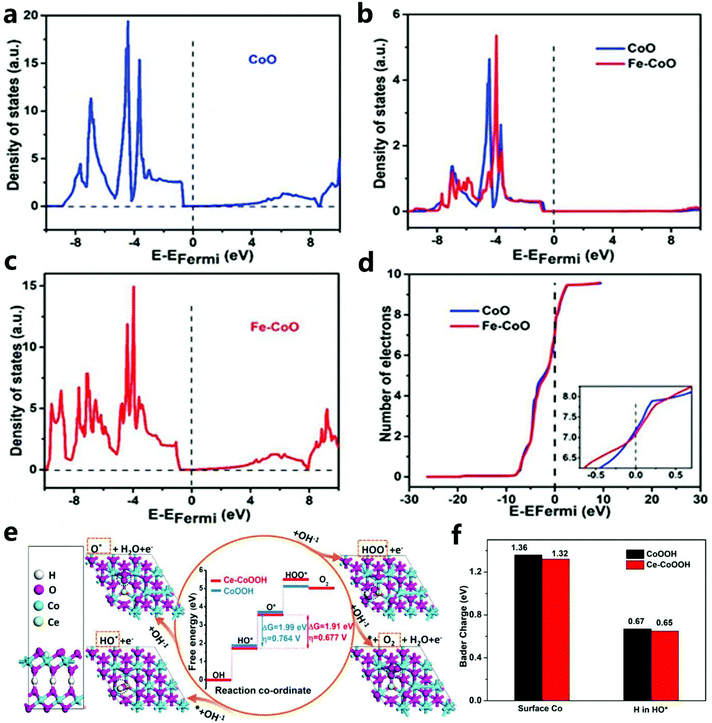 | ||
| Fig. 25 (a) CoO total density of states. (b) The partial density of the Co 3d orbital state. (c) Fe–CoO total density of states. (d) The number of electrons in the 3d orbital of each Co atom in CoO and Fe–CoO.103 Copyright © 2018 Elsevier Ltd. All rights reserved. (e) Atomic model and the DFT calculated results for the OER on CoOOH and Ce–CoOOH. (f) Bader charge analysis for surface Co ions and H in HO* adsorption on CoOOH and Ce–CoOOH.189 Copyright @ 2020, American Chemical Society. | ||
Through DFT calculations, Dong et al.189 confirmed that the doping of S optimized the charge environment of the active sites of Co–N and CoO, and promoted the adsorption and desorption of oxygen-containing intermediates, thereby improving the OER performance. By calculating the typical adsorption energy of the four basic steps, Dong et al. also studied the free energy diagram of Ce–CoOOH in the OER process (Fig. 25e). To simplify the calculation, they set the OER model to be constructed based on the (001) plane of β-CoOOH (β-CoOOH has the best stability under OER conditions). Through the step diagram, they find that the rate-determining step of OER catalysis is the deprotonation process of HO* to O*, and Ce-doped CoOOH has a lower ΔG and overpotential. In addition, to prove that electrons were transferred from Ce to nearby Co sites, and then to H and HO* (Fig. 25f), the poorer charges of Co and H were also studied. Then, they found that electron transfer between Ce and H weakened the H–O bond, which helped to reduce the energy barrier in the rate-determining step and improve the OER performance.
In short, this section first uses DFT theoretical calculations to determine the electronic structure and catalytic activity of saturated and unsaturated ZIF-67. It also proves that the role of ligands in catalytic activity may be related to the redistribution of charges on active sites due to the change in coordination. In addition, through DFT theoretical calculations, it is confirmed that the sites on ZIF-67 are conducive to metal adsorption, and it is found that the delocalized π electrons in the imidazole group are the most critical for a single atom. They are used as fixed sites, initially forming a strong bond with M ions and keeping them isolated by thermal carbonization. Secondly, the DFT theoretical calculations confirmed the mechanism of Co–C conjugation and N species doping, and revealed that Co3O4/NPC and CoOOH/graphene had excellent performances in the OER catalytic reaction.
Third, by analyzing the effects of Ce, Fe, and S doping on ZIF-67 derivatives, it can be found that Fe doping is beneficial for the formation of adsorbed OOH species, S doping promotes the adsorption and desorption of oxygen-containing intermediates, and Ce doping not only promotes the adsorption and desorption process of the intermediate, but also weakens the H–O bond, thereby promoting the OER performance.
8 Summary and outlook
Due to inherent poor conductivity of ZIF-67 and its derivatives, other factors need to be considered to improve the design of the composition of the OER catalytic material and the electron transport rate in the structure configuration to enhance the catalytic performance. However, many good properties of nanostructures benefit from the synergy of structural tunability and dopants. Therefore, this review summarizes the OER catalysis of ZIF-67 and its derivatives from the aspects of morphology engineering, composition engineering, doping, and corresponding single-atom catalysis. In addition, the DFT theoretical calculations are summarized to illustrate the mechanism of OER catalysis by ZIF-67 and its derivatives. Through the summary of various aspects, we find that ZIF-67 and its derivatives still have some problems and challenges that cannot be ignored in OER electrocatalysis:(1) Although there are few studies on the use of ZIF-67-based nanoarrays and single-atom catalysts for OER catalysis, it can be seen that they exhibit good performances at high current densities, which is of great significance to the realization of catalytic industrialization. Therefore, it is necessary to conduct more in-depth research on these catalysts.
(2) In the OER catalysis study based on ZIF-67, no investigations into two-dimensional ZIF-67 were performed. However, two-dimensional catalytic materials exhibit excellent catalytic performance, so research in this field is still necessary.
(3) Research into the doping of ZIF-67 and its derivatives also needs to be perfected, for example, the co-doping of multiple cations or anions and the doping of specific structures.
(4) In terms of ZIF-67 and its derivatives, there is little research on the catalytic mechanism of the OER, and the current mechanism mainly illustrates the discussion based on the Co–N–C active site, which simplifies the actual reaction of the catalyst. Therefore, more in-depth and systematic research is needed, and it is necessary to further improve theoretical guidance for the ZIF-67 system.
Finally, inspired by the directional but flexible structure and inherent advantages of adjustable ZIF-67 components, the exploration of their potential performance and applications will not only be limited to energy storage and conversion but will also lead to long-term developments. With continuous research into the basic science behind complex reaction processes and the accelerated development of characterization and synthesis technology, ZIF-67 and its derivatives will become hot topics for research in the field of catalysis.
Conflicts of interest
The authors declare that they have no known competing financial interests or personal relationships that could have appeared to influence the work reported in this paper.Acknowledgements
This work was supported by the National Natural Science Foundation of China (Grant No. 51971058 and 52071072), the Fundamental Research Funds for the Central Universities (Grant No. N182312007 and N2023001), the Program for Liaoning Innovative Talents in University (No. LCR2018016), the Liaoning Provincial Natural Science Foundation of China (No. 2019-MS-244), the Liaoning Revitalization Talents Program (No. XLYC1907031), and the Liaoning BaiQianWan Talents Program (No. 2020921082).References
- X. Zou and Y. Zhang, Chem. Soc. Rev., 2015, 44, 5148–5180 RSC.
- Y. Jiao, Y. Zheng, M. Jaroniec and S. Z. Qiao, Chem. Soc. Rev., 2015, 44, 2060–2086 RSC.
- P. G. Bruce, S. A. Freunberger, L. J. Hardwick and J. M. Tarascon, Nat. Mater., 2012, 11, 19–29 CrossRef CAS PubMed.
- N. S. Lewis and D. G. Nocera, Proc. Natl. Acad. Sci. U. S. A., 2006, 103, 15729–15735 CrossRef CAS PubMed.
- B. C. H. Steele and A. Heinzel, Nature, 2001, 414, 345–352 CrossRef CAS PubMed.
- C. C. L. McCrory, S. H. Jung, J. C. Peters and T. F. Jaramillo, J. Am. Chem. Soc., 2013, 135, 16977–16987 CrossRef CAS PubMed.
- I. C. Man, H. Y. Su, F. Calle-Vallejo, H. A. Hansen, J. I. Martinez, N. G. Inoglu, J. Kitchin, T. F. Jaramillo, J. K. Norskov and J. Rossmeisl, ChemCatChem, 2011, 3, 1159–1165 CrossRef CAS.
- Z. Y. Ni, H. Wen, S. Q. Zhang, R. Guo, N. Su, X. W. Liu and C. M. Liu, ChemCatChem, 2020, 12, 4962–4999 CrossRef CAS.
- D. Li, H. Liu and L. Feng, Energy Fuels, 2020, 34, 13491–13522 CrossRef CAS.
- P. E. M. Siegbahn, J. Am. Chem. Soc., 2009, 131, 18238–18239 CrossRef CAS PubMed.
- T. A. Betley, Y. Surendranath, M. V. Childress, G. E. Alliger, R. Fu, C. C. Cummins and D. G. Nocera, Philos. Trans. R. Soc., B, 2008, 363, 1293–1303 CrossRef CAS PubMed.
- T. Reier, H. N. Nong, D. Teschner, R. Schlogl and P. Strasser, Adv. Energy Mater., 2017, 7, 1601275 CrossRef.
- X. J. Liu, Z. Chang, L. Luo, T. H. Xu, X. D. Lei, J. F. Liu and X. M. Sun, Chem. Mater., 2014, 26, 1889–1895 CrossRef CAS.
- C. Xia, Q. Jiang, C. Zhao, M. N. Hedhili and H. N. Alshareef, Adv. Mater., 2016, 28, 77–85 CrossRef CAS PubMed.
- R. Guo, Y. He, T. Yu, P. Cheng, J. You, H. Lin, C.-T. Chen, T. Chan, X. Liu and Z. Hu, Chem. Eng. J., 2020, 127587 Search PubMed.
- Y. Lee, J. Suntivich, K. J. May, E. E. Perry and Y. Shao-Horn, J. Phys. Chem. Lett., 2012, 3, 399–404 CrossRef CAS PubMed.
- S. Cherevko, S. Geiger, O. Kasian, N. Kulyk, J. P. Grote, A. Savan, B. R. Shrestha, S. Merzlikin, B. Breitbach, A. Ludwig and K. J. J. Mayrhofer, Catal. Today, 2016, 262, 170–180 CrossRef CAS.
- G. Wu, K. L. More, C. M. Johnston and P. Zelenay, Science, 2011, 332, 443–447 CrossRef CAS PubMed.
- G. Wu and P. Zelenay, Acc. Chem. Res., 2013, 46, 1878–1889 CrossRef CAS PubMed.
- S. Zhang, T. Yu, H. Wen, Z. Ni, Y. He, R. Guo, J. You and X. Liu, Chem. Commun., 2020, 56, 15387–15405 RSC.
- T. Y. Ma, S. Dai, M. Jaroniec and S. Z. Qiao, J. Am. Chem. Soc., 2014, 136, 13925–13931 CrossRef CAS PubMed.
- J. Suntivich, K. J. May, H. A. Gasteiger, J. B. Goodenough and Y. Shao-Horn, Science, 2011, 334, 1383–1385 CrossRef CAS PubMed.
- M. Gong, Y. G. Li, H. L. Wang, Y. Y. Liang, J. Z. Wu, J. G. Zhou, J. Wang, T. Regier, F. Wei and H. J. Dai, J. Am. Chem. Soc., 2013, 135, 8452–8455 CrossRef CAS PubMed.
- M. S. Burke, L. J. Enman, A. S. Batchellor, S. H. Zou and S. W. Boettcher, Chem. Mater., 2015, 27, 7549–7558 CrossRef CAS.
- J. Quinonero, T. Lana-Villarreal and R. Gomez, Int. J. Hydrogen Energy, 2020, 45, 17076–17087 CrossRef CAS.
- X. K. Gu, J. C. A. Camayang, S. Samira and E. Nikolla, J. Catal., 2020, 388, 130–140 CrossRef CAS.
- S. W. Lee, C. Carlton, M. Risch, Y. Surendranath, S. Chen, S. Furutsuki, A. Yamada, D. G. Nocera and Y. Shao-Horn, J. Am. Chem. Soc., 2012, 134, 16959–16962 CrossRef CAS PubMed.
- A. Corma, H. Garcia and F. X. Llabrés i Xamena, Chem. Rev., 2010, 110, 4606–4655 CrossRef CAS PubMed.
- J. Gascon, A. Corma, F. Kapteijn and F. X. Llabrés i Xamena, ACS Catal., 2014, 4, 361–378 CrossRef CAS.
- J. Jiang, L. Huang, X. M. Liu and L. H. Ai, ACS Appl. Mater. Interfaces, 2017, 9, 7193–7201 CrossRef CAS PubMed.
- S. Wang and X. Wang, Small, 2015, 11, 3097–3112 CrossRef CAS PubMed.
- S. Wang and X. Wang, Angew. Chem., Int. Ed., 2016, 55, 2308–2320 CrossRef CAS.
- J. Ryu, N. Jung, J. H. Jang, H.-J. Kim and S. J. Yoo, ACS Catal., 2015, 5, 4066–4074 CrossRef CAS.
- A. Phan, C. J. Doonan, F. J. Uribe-Romo, C. B. Knobler, M. O'Keeffe and O. M. Yaghi, Acc. Chem. Res., 2010, 43, 58–67 CrossRef CAS PubMed.
- N. L. Torad, M. Hu, S. Ishihara, H. Sukegawa, A. A. Belik, M. Imura, K. Ariga, Y. Sakka and Y. Yamauchi, Small, 2014, 10, 2096–2107 CrossRef CAS PubMed.
- B. You, N. Jiang, M. Sheng, W. S. Drisdell, J. Yano and Y. Sun, ACS Catal., 2015, 5, 7068–7076 CrossRef CAS.
- B. You, N. Jiang, M. Sheng, S. Gul, J. Yano and Y. Sun, Chem. Mater., 2015, 27, 7636–7642 CrossRef CAS.
- L. Jiao, Y.-X. Zhou and H.-L. Jiang, Chem. Sci., 2016, 7, 1690–1695 RSC.
- Z. P. Lai, Curr. Opin. Chem. Eng., 2018, 20, 78–85 CrossRef.
- X. B. Yang, J. Chen, Y. Q. Q. Chen, P. J. Feng, H. X. Lai, J. T. Li and X. T. Luo, Nano-Micro Lett., 2018, 10, 15 CrossRef PubMed.
- J. W. Wan, D. Liu, H. Xiao, H. P. Rong, S. Guan, F. Xie, D. S. Wang and Y. D. Li, ChemComm, 2020, 56, 4316–4319 RSC.
- W. Zheng, M. Liu and L. Y. S. Lee, ACS Catal., 2020, 10, 81–92 CrossRef CAS.
- H. B. Aiyappa, P. Wilde, T. Quast, J. Masa, C. Andronescu, Y.-T. Chen, M. Muhler, R. A. Fischer and W. Schuhmann, Angew. Chem., Int. Ed., 2019, 58, 8927–8931 CrossRef CAS PubMed.
- T. Tarnev, H. B. Aiyappa, A. Botz, T. Erichsen, A. Ernst, C. Andronescu and W. Schuhmann, Angew. Chem., Int. Ed., 2019, 58, 14265–14269 CrossRef CAS PubMed.
- S. Xun, Y. Xu, J. He, D. Jiang, R. Yang, D. Li and M. Chen, J. Alloys Compd., 2019, 806, 1097–1104 CrossRef CAS.
- R. Zhu, J. Ding, Y. Xu, J. Yang, Q. Xu and H. Pang, Small, 2018, 14, 1803576 CrossRef PubMed.
- H. Xu, J. Cao, C. Shan, B. Wang, P. Xi, W. Liu and Y. Tang, Angew. Chem., Int. Ed., 2018, 57, 8654–8658 CrossRef CAS PubMed.
- M. Khalid, A. M. B. Honorato, H. Varela and L. Dai, Nano Energy, 2018, 45, 127–135 CrossRef CAS.
- Z. Li, Z. Jiang, W. Zhu, C. He, P. Wang, X. Wang, T. Li and L. Tian, Appl. Surf. Sci., 2020, 504, 144368 CrossRef CAS.
- W. Wu, J. Liu, G. Chen, Y. Chen and C. Xu, Int. J. Hydrogen Energy, 2020, 45, 1948–1958 CrossRef CAS.
- Q. Zha, W. Xu, X. Li and Y. Ni, Dalton Trans., 2019, 48, 12127–12136 RSC.
- X. Guo, G. Liang and A. Gu, Int. J. Hydrogen Energy, 2019, 44, 31020–31028 CrossRef CAS.
- Y. Wang, Y. Y. Wang, L. Zhang, C. S. Liu and H. Pang, Inorg. Chem. Front., 2019, 6, 2514–2520 RSC.
- J. Xu, Y. Zhao, M. Li, G. Fan, L. Yang and F. Li, Electrochim. Acta, 2019, 307, 275–284 CrossRef CAS.
- Y. Wang, M. Zhao, Q. Zhao, Q. Li and H. Pang, Nanoscale, 2018, 10, 15755–15762 RSC.
- D. Dong, Y. Liu and J. Li, Part. Part. Syst. Charact., 2016, 33, 887–895 CrossRef CAS.
- L. Li, T. Tian, J. Jiang and L. Ai, J. Power Sources, 2015, 294, 103–111 CrossRef CAS.
- Q. Shi, S. Fu, C. Zhu, J. Song, D. Du and Y. Lin, Mater. Horiz., 2019, 6, 684–702 RSC.
- J.-J. Zhou, X. Han, K. Tao, Q. Li, Y.-L. Li, C. Chen and L. Han, Chem. Eng. J., 2018, 354, 875–884 CrossRef CAS.
- H. Zhu, J. F. Zhang, R. P. Yanzhang, M. L. Du, Q. F. Wang, G. H. Gao, J. D. Wu, G. M. Wu, M. Zhang, B. Liu, J. M. Yao and X. W. Zhang, Adv. Mater., 2015, 27, 4752–4759 CrossRef CAS PubMed.
- P. Strasser, Acc. Chem. Res., 2016, 49, 2658–2668 CrossRef CAS PubMed.
- V. K. Abdelkader-Fernandez, D. M. Fernandes, S. S. Balula, L. Cunha-Silva and C. Freire, J. Mater. Chem. A, 2020, 8, 13509–13521 RSC.
- W. F. Xie, Z. H. Li, M. F. Shao and M. Wei, Front. Chem. Sci. Eng., 2018, 12, 537–554 CrossRef CAS.
- J.-F. Qin, J.-Y. Xie, N. Wang, B. Dong, T.-S. Chen, Z.-Y. Lin, Z.-Z. Liu, Y.-N. Zhou, M. Yang and Y.-M. Chai, J. Colloid Interface Sci., 2020, 562, 279–286 CrossRef CAS PubMed.
- J. Cao, C. Lei, J. Yang, X. Cheng, Z. Li, B. Yang, X. Zhang, L. Lei, Y. Hou and K. Ostrikov, J. Mater. Chem. A, 2018, 6, 18877–18883 RSC.
- S. Li, S. Peng, L. Huang, X. Cui, A. M. Al-Enizi and G. Zheng, ACS Appl. Mater. Interfaces, 2016, 8, 20534–20539 CrossRef CAS.
- X. Jia, J. Wu, K. Lu, Y. Li, X. Qiao, J. Kaelin, S. Lu, Y. Cheng, X. Wu and W. Qin, J. Mater. Chem. A, 2019, 7, 14302–14308 RSC.
- X. Li, S. You, J. Du, Y. Dai, H. Chen, Z. Cai, N. Ren and J. Zou, J. Mater. Chem. A, 2019, 7, 25853–25864 RSC.
- Y. Wang, Y. Wang, L. Zhang, C.-S. Liu and H. Pang, Inorg. Chem. Front., 2019, 6, 2514–2520 RSC.
- X. Wang, L. Yu, B. Y. Guan, S. Song and X. W. Lou, Adv. Mater., 2018, 30, 1801211 CrossRef PubMed.
- V. Ganesan, J. Son and J. Kim, Nanoscale, 2021, 13, 4569–4575 RSC.
- Q. Y. Li, L. Zhang, Y. X. Xu, Q. Li, H. Xue and H. Pang, ACS Sustainable Chem. Eng., 2019, 7, 5027–5033 CrossRef CAS.
- D. Ding, K. Shen, X. Chen, H. Chen, J. Chen, T. Fan, R. Wu and Y. Li, ACS Catal., 2018, 8, 7879–7888 CrossRef CAS.
- X. Li, Q. Jiang, S. Dou, L. Deng, J. Huo and S. Wang, J. Mater. Chem. A, 2016, 4, 15836–15840 RSC.
- A. Aijaz, J. Masa, C. Roesler, W. Xia, P. Weide, A. J. R. Botz, R. A. Fischer, W. Schuhmann and M. Muhler, Angew. Chem., Int. Ed., 2016, 55, 4087–4091 CrossRef CAS PubMed.
- D. L. Li, Z. Zong, Z. H. Tang, Z. Liu, S. W. Chen, Y. Tian and X. F. Wang, ACS Sustainable Chem. Eng., 2018, 6, 5105–5114 CrossRef CAS.
- J.-G. Li, K. Xie, H. Sun, Z. Li, X. Ao, Z. Chen, K. K. Ostrikov, C. Wang and W. Zhang, ACS Appl. Mater. Interfaces, 2019, 11, 36649–36657 CrossRef CAS PubMed.
- J.-G. Li, Y. Gu, H. Sun, L. Lv, Z. Li, X. Ao, X. Xue, G. Hong and C. Wang, Nanoscale, 2019, 11, 19959–19968 RSC.
- D. Kim, D. Kim, Y. Jeon, Y. Li, J. Lee, J. Kang, L. Y. S. Lee and Y. Piao, Electrochim. Acta, 2019, 299, 213–221 CrossRef CAS.
- M. Li, C. Bao, Y. Liu, J. Meng, X. Liu, Y. Cai, D. Wuu, Y. Zong, T.-P. Loh and Z. Wang, RSC Adv., 2019, 9, 16534–16540 RSC.
- V. Jose, A. Jayakumar and J.-M. Lee, ChemElectroChem, 2019, 6, 1485–1491 CrossRef CAS.
- Y. Pan, K. Sun, S. Liu, X. Cao, K. Wu, W.-C. Cheong, Z. Chen, Y. Wang, Y. Li, Y. Liu, D. Wang, Q. Peng, C. Chen and Y. Li, J. Am. Chem. Soc., 2018, 140, 2610–2618 CrossRef CAS PubMed.
- J. Li, G. Li, J. Wang, C. Xue, X. Li, S. Wang, B. Han, M. Yang and L. Li, Inorg. Chem. Front., 2020, 7, 191–197 RSC.
- J. Sun, G. Li, K. Zheng, Y. He, Z. Guo and C. Xu, Appl. Surf. Sci., 2020, 517, 146183 CrossRef CAS.
- J. Shi, F. Qiu, W. Yuan, M. Guo and Z.-H. Lu, Chem. Eng. J., 2021, 403, 126312 CrossRef CAS.
- Y. Y. Wu, G. D. Li, Y. P. Liu, L. Yang, X. R. Lian, T. Asefa and X. X. Zou, Adv. Funct. Mater., 2016, 26, 4839–4847 CrossRef CAS.
- R. Shi, J. Wang, Z. Wang, T. Li and Y.-F. Song, J. Energy Chem., 2019, 33, 74–80 CrossRef.
- Y. Li, Z. Wang, J. Hu, S. Li, Y. Du, X. Han and P. Xu, Adv. Funct. Mater., 2020, 30, 1910498 CrossRef CAS.
- J. Kim, H. Jin, A. Oh, H. Baik, S. H. Joo and K. Lee, Nanoscale, 2017, 9, 15397–15406 RSC.
- Y. Men, X. Liu, F. Yang, F. Ke, G. Cheng and W. Luo, Inorg. Chem., 2018, 57, 10649–10655 CrossRef CAS PubMed.
- Q. Liang, Z. Chen, X. Chen and Y. Li, J. Mater. Chem. A, 2019, 7, 20310–20316 RSC.
- J. Li, S. Lu, H. Huang, D. Liu, Z. Zhuang and C. Zhong, ACS Sustainable Chem. Eng., 2018, 6, 10021–10029 CrossRef CAS.
- F. Lyu, Y. Bai, Z. Li, W. Xu, Q. Wang, J. Mao, L. Wang, X. Zhang and Y. Yin, Adv. Funct. Mater., 2017, 27, 1702324 CrossRef.
- H. J. Fan, M. Knez, R. Scholz, D. Hesse, K. Nielsch, M. Zacharias and U. Gosele, Nano Lett., 2007, 7, 993–997 CrossRef CAS PubMed.
- J. Park, T. Kwon, J. Kim, H. Jin, H. Y. Kim, B. Kim, S. H. Joo and K. Lee, Chem. Soc. Rev., 2018, 47, 8173–8202 RSC.
- J.-G. Li, H. Sun, L. Lv, Z. Li, X. Ao, C. Xu, Y. Li and C. Wang, ACS Appl. Mater. Interfaces, 2019, 11, 8106–8114 CrossRef CAS.
- F. Calle-Vallejo, J. Tymoczko, V. Colic, Q. H. Vu, M. D. Pohl, K. Morgenstern, D. Loffreda, P. Sautet, W. Schuhmann and A. S. Bandarenka, Science, 2015, 350, 185–189 CrossRef CAS PubMed.
- F. Calle-Vallejo, M. D. Pohl, D. Reinisch, D. Loffreda, P. Sautet and A. S. Bandarenka, Chem. Sci., 2017, 8, 2283–2289 RSC.
- T. Asset, R. Chattot, J. Drnec, P. Bordet, N. Job, F. Maillard and L. Dubau, ACS Appl. Mater. Interfaces, 2017, 9, 25298–25307 CrossRef CAS PubMed.
- T. Asset, N. Job, Y. Busby, A. Crisci, V. Martin, V. Stergiopoulos, C. Bonnaud, A. Serov, P. Atanassov, R. Chattot, L. Dubau and F. Maillard, ACS Catal., 2018, 8, 893–903 CrossRef CAS.
- Z. Yu, Y. Bai, S. Zhang, Y. Liu, N. Zhang and K. Sun, Int. J. Hydrogen Energy, 2018, 43, 8815–8823 CrossRef CAS.
- L. Zhang, T. Mi, M. A. Ziaee, L. Liang and R. Wang, J. Mater. Chem. A, 2018, 6, 1639–1647 RSC.
- X. Ren, F. Lyu, J. Yang, F. Wang, L. Xue, L. Wang, X. Zhang and Q. Wang, Electrochim. Acta, 2019, 296, 418–426 CrossRef CAS.
- X. Liu, L. Zhou, L. Huang, L. Chen, L. Long, S. Wang, X. Xu, M. Liu, W. Yang and J. Jia, Electrochim. Acta, 2019, 318, 883–891 CrossRef CAS.
- J. Zhang, F. Li, W. Chen, C. Wang and D. Cai, Electrochim. Acta, 2019, 300, 123–130 CrossRef CAS.
- H. Chu, D. Zhang, B. Jin and M. Yang, Appl. Catal., B, 2019, 255, 117744 CrossRef CAS.
- H. Zhang, Z. Yang, X. Wang, S. Yan, T. Zhou, C. Zhang, S. G. Telfer and S. Liu, Nanoscale, 2019, 11, 17384–17395 RSC.
- J. Wu, L. Hu, N. Wang, Y. Li, D. Zhao, L. Li, X. Peng, Z. Cui, L.-J. Ma, Y. Tian and X. Wang, Appl. Catal., B, 2019, 254, 55–65 CrossRef CAS.
- H. Xu, H. Shang, C. Wang, L. Jin, C. Chen, C. Wang and Y. Du, Appl. Catal., B, 2020, 265, 118605 CrossRef.
- Y. Li, M. Cui, T. Li, Y. Shen, Z. Si and H.-G. Wang, Int. J. Hydrogen Energy, 2020, 45, 16540–16549 CrossRef CAS.
- X. Gu, Z. Liu, H. Liu, C. Pei and L. Feng, Chem. Eng. J., 2021, 403, 126371 CrossRef CAS.
- Z. Lei, Y. Tan, Z. Zhang, W. Wu, N. Cheng, R. Chen, S. Mu and X. Sun, Nano Res., 2021, 14, 868–878 CrossRef CAS.
- J. G. Hou, Y. Z. Wu, B. Zhang, S. Y. Cao, Z. W. Li and L. C. Sun, Adv. Funct. Mater., 2019, 29, 1808367 CrossRef.
- R. Guo, A. G. Yan, J. J. Xu, B. T. Xu, T. T. Li, X. W. Liu, T. F. Yi and S. H. Luo, J. Alloys Compd., 2020, 817, 153246 CrossRef CAS.
- G. R. Cai, W. Zhang, L. Jiao, S. H. Yu and H. L. Jiang, Chem, 2017, 2, 791–802 CAS.
- F. H. Kong, W. W. Zhang, L. P. Sun, L. H. Huo and H. Zhao, ChemSusChem, 2019, 12, 3592–3601 CrossRef CAS PubMed.
- P. Li, J. Z. Wang, N. Cai, L. Wang, J. Tong and F. Q. Yu, ChemCatChem, 2020, 12, 1639–1646 CrossRef CAS.
- J. J. Zhou, X. Han, K. Tao, Q. Li, Y. L. Li, C. Chen and L. Han, Chem. Eng. J., 2018, 354, 875–884 CrossRef CAS.
- M. Guo, Y. Li, L. Zhou, Q. Zheng, W. Jie, F. Xie, C. Xu and D. Lin, Electrochim. Acta, 2019, 298, 525–532 CrossRef CAS.
- S. Song, Y. Wang, W. Li, P. Tian, S. Zhou, H. Gao, X. Tian and J. Zang, J. Alloys Compd., 2020, 827, 154299 CrossRef CAS.
- S. Wang, X. Yang, Z. Liu, D. Yang and L. Feng, Nanoscale, 2020, 12, 10827–10833 RSC.
- H. Wu, J. Wang, J. Yan, Z. Wu and W. Jin, Nanoscale, 2019, 11, 20144–20150 RSC.
- H. Liu, Z. Liu and L. Feng, Nanoscale, 2019, 11, 16017–16025 RSC.
- Y. Du, G. Cheng and W. Luo, Nanoscale, 2017, 9, 6821–6825 RSC.
- Y. Zhao, S. Xing, X. Meng, J. Zeng, S. Yin, X. Li and Y. Chen, Nanoscale, 2019, 11, 9319–9326 RSC.
- S. Dilpazir, R. Liu, M. Yuan, M. Imran, Z. Liu, Y. Xie, H. Zhao and G. Zhang, J. Mater. Chem. A, 2020, 8, 10865–10874 RSC.
- C.-X. Zhao, B.-Q. Li, M. Zhao, J.-N. Liu, L.-D. Zhao, X. Chen and Q. Zhang, Energy Environ. Sci., 2020, 13, 1711–1716 RSC.
- X. W. Liu, Z. Y. Ni, Y. He, N. Su, R. Guo, Q. Wang and T. F. Yi, New J. Chem., 2019, 43, 8711–8721 RSC.
- B. He, X.-C. Wang, L.-X. Xia, Y.-Q. Guo, Y.-W. Tang, Y. Zhao, Q.-L. Hao, T. Yu, H.-K. Liu and Z. Su, ChemSusChem, 2020, 13, 5239–5247 CrossRef CAS PubMed.
- C. Lin, P. Wang, H. Jin, J. Zhao, D. Chen, S. Liu, C. Zhang and S. Mu, Dalton Trans., 2019, 48, 16555–16561 RSC.
- S. L. Zhang, B. Y. Guan, X. F. Lu, S. Xi, Y. Du and X. W. Lou, Adv. Mater., 2020, 32, 2002235 CrossRef CAS PubMed.
- K. Xu, Y. Sun, Y. Sun, Y. Zhang, G. Jia, Q. Zhang, L. Gu, S. Li, Y. Li and H. J. Fan, ACS Energy Lett., 2018, 3, 2750–2756 CrossRef CAS.
- Y. Sun, K. Xu, Z. Wei, H. Li, T. Zhang, X. Li, W. Cai, J. Ma, H. J. Fan and Y. Li, Adv. Mater., 2018, 30, 1802121 CrossRef PubMed.
- X. Huang, J. Wang, H. Bao, X. Zhang and Y. Huang, ACS Appl. Mater. Interfaces, 2018, 10, 7180–7190 CrossRef CAS PubMed.
- Y. Tan, Z. Zhang, Z. Lei, W. Wu, W. Zhu, N. Cheng and S. Mu, J. Power Sources, 2020, 473, 228570 CrossRef CAS.
- F. Tang, X. Gao and Z. Jin, Electrochim. Acta, 2020, 337, 135807 CrossRef CAS.
- W.-H. Lai, L.-F. Zhang, W.-B. Hua, S. Indris, Z.-C. Yan, Z. Hu, B. Zhang, Y. Liu, L. Wang, M. Liu, R. Liu, Y.-X. Wang, J.-Z. Wang, Z. Hu, H.-K. Liu, S.-L. Chou and S.-X. Dou, Angew. Chem., Int. Ed., 2019, 58, 11868–11873 CrossRef CAS PubMed.
- L. Tao, C.-Y. Lin, S. Dou, S. Feng, D. Chen, D. Liu, J. Huo, Z. Xia and S. Wang, Nano Energy, 2017, 41, 417–425 CrossRef CAS.
- S. Dilpazir, H. He, Z. Li, M. Wang, P. Lu, R. Liu, Z. Xie, D. Gao and G. Zhang, ACS Appl. Energy Mater., 2018, 1, 3283–3291 CrossRef CAS.
- X. Sun, S. Sun, S. Gu, Z. Liang, J. Zhang, Y. Yang, Z. Deng, P. Wei, J. Peng, Y. Xu, C. Fang, Q. Li, J. Han, Z. Jiang and Y. Huang, Nano Energy, 2019, 61, 245–250 CrossRef CAS.
- Y. Y. Liang, Y. G. Li, H. L. Wang, J. G. Zhou, J. Wang, T. Regier and H. J. Dai, Nat. Mater., 2011, 10, 780–786 CrossRef CAS PubMed.
- H. Li, Y. He, T. He, S. Yan, X. Ma and J. Chen, J. Mater. Sci.: Mater. Electron., 2019, 30, 21388–21397 CrossRef CAS.
- L. Han, S. J. Dong and E. K. Wang, Adv. Mater., 2016, 28, 9266–9291 CrossRef CAS PubMed.
- Q. L. Zhu and Q. Xu, Chem. Soc. Rev., 2014, 43, 5468–5512 RSC.
- N. Stock and S. Biswas, Chem. Rev., 2012, 112, 933–969 CrossRef CAS PubMed.
- T. Meng, J. Qin, S. Wang, D. Zhao, B. Mao and M. Cao, J. Mater. Chem. A, 2017, 5, 7001–7014 RSC.
- E. Zhang, Y. Xie, S. Ci, J. Jia, P. Cai, L. Yi and Z. Wen, J. Mater. Chem. A, 2016, 4, 17288–17298 RSC.
- X. Yang, J. Chen, Y. Chen, P. Feng, H. Lai, J. Li and X. Luo, Nano-Micro Lett., 2018, 10, 15 CrossRef PubMed.
- H. Zhou, M. Zheng, H. Tang, B. Xu, Y. Tang and H. Pang, Small, 2020, 16, e1904252 CrossRef PubMed.
- W. Xu, W. Xie and Y. Wang, ACS Appl. Mater. Interfaces, 2017, 9, 28642–28649 CrossRef CAS PubMed.
- X. Yan, L. Tian, S. Atkins, Y. Liu, J. Murowchick and X. Chen, ACS Sustainable Chem. Eng., 2016, 4, 3743–3749 CrossRef CAS.
- K. Jin, J. Park, J. Lee, K. D. Yang, G. K. Pradhan, U. Sim, D. Jeong, H. L. Jang, S. Park, D. Kim, N.-E. Sung, S. H. Kim, S. Han and K. T. Nam, J. Am. Chem. Soc., 2014, 136, 7435–7443 CrossRef CAS PubMed.
- H. Kim, J. Park, I. Park, K. Jin, S. E. Jerng, S. H. Kim, K. T. Nam and K. Kang, Nat. Commun., 2015, 6, 8253 CrossRef CAS PubMed.
- J. Wang, C. Chen, N. Cai, M. Wang, H. Li and F. Yu, Nanoscale, 2021, 13, 1354–1363 RSC.
- J. Li, G. Du, X. Cheng, P. Feng and X. Luo, Chin. J. Catal., 2018, 39, 982–987 CrossRef CAS.
- T. Liu, F. Yang, G. Cheng and W. Luo, Small, 2018, 14, 1703748 CrossRef PubMed.
- Y. Guo, J. Tang, Z. Wang, Y.-M. Kang, Y. Bando and Y. Yamauchi, Nano Energy, 2018, 47, 494–502 CrossRef CAS.
- L.-L. Wu, Q.-S. Wang, J. Li, Y. Long, Y. Liu, S.-Y. Song and H.-J. Zhang, Small, 2018, 14, 1704035 CrossRef PubMed.
- S. Liu, X. Zhang, G. Wang, Y. Zhang and H. Zhang, ACS Appl. Mater. Interfaces, 2017, 9, 34269–34278 CrossRef CAS PubMed.
- Y. Guo, J. Tang, H. Qian, Z. Wang and Y. Yamauchi, Chem. Mater., 2017, 29, 5566–5573 CrossRef CAS.
- S. Anantharaj, S. R. Ede, K. Sakthikumar, K. Karthick, S. Mishra and S. Kundu, ACS Catal., 2016, 6, 8069–8097 CrossRef CAS.
- Y. Zheng, L. Zhang, H. Huang, F. Wang, L. Yin, H. Jiang, D. Wang, J. Yang and G. Zuo, Int. J. Hydrogen Energy, 2019, 44, 27465–27471 CrossRef CAS.
- D. H. He, X. L. Wu, W. Liu, C. J. Lei, C. L. Yu, G. K. Zheng, J. J. Pan, L. C. Lei and X. W. Zhang, Chin. Chem. Lett., 2019, 30, 229–233 CrossRef CAS.
- K. Ao, J. Dong, C. Fan, D. Wang, Y. Cai, D. Li, F. Huang and Q. Wei, ACS Sustainable Chem. Eng., 2018, 6, 10952–10959 CrossRef CAS.
- X. Wang, X. Huang, W. Gao, Y. Tang, P. Jiang, K. Lan, R. Yang, B. Wang and R. Li, J. Mater. Chem. A, 2018, 6, 3684–3691 RSC.
- M. Yang, W. Lu, R. Jin, X.-C. Liu, S. Song and Y. Xing, ACS Sustainable Chem. Eng., 2019, 7, 12214–12221 RSC.
- G.-l. Zhuang, Y.-f. Gao, X. Zhou, X.-y. Tao, J.-m. Luo, Y.-j. Gao, Y.-l. Yan, P.-y. Gao, X. Zhong and J.-g. Wang, Chem. Eng. J., 2017, 330, 1255–1264 CrossRef CAS.
- S. Liu, X. W. Chen, S. Wang, Z. Yang, J. X. Gao, P. Zhu, X. S. Zhao and G. X. Wang, Electrochim. Acta, 2018, 292, 707–717 CrossRef CAS.
- P. Li, J. Wang, N. Cai, L. Wang, J. Tong and F. Yu, ChemCatChem, 2020, 12, 1639–1646 CrossRef CAS.
- J. M. Zhou, H. Y. Zheng, Q. J. Luan, X. B. Huang, Y. Li, Z. S. Xi, G. L. Lu, L. W. Xing and Y. Q. Li, Sustainable Energy Fuels, 2019, 3, 3201–3207 RSC.
- L. Xu, X. Wang, L. Chai, T.-T. Li, Y. Hu, J. Qian and S. Huang, Mater. Lett., 2019, 248, 181–184 CrossRef CAS.
- X. Wen, X. Yang, M. Li, L. Bai and J. Guan, Electrochim. Acta, 2019, 296, 830–841 CrossRef CAS.
- Y. Li, H. Xu, H. Huang, C. Wang, L. Gao and T. Ma, ChemComm, 2018, 54, 2739–2742 RSC.
- Y. Hao, Y. Xu, J. Liu and X. Sun, J. Mater. Chem. A, 2017, 5, 5594–5600 RSC.
- P. He, X. Y. Yu and X. W. Lou, Angew. Chem., Int. Ed., 2017, 56, 3897–3900 CrossRef CAS PubMed.
- C. Wang, W. Chen, D. Yuan, S. Qian, D. Cai, J. Jiang and S. Zhang, Nano Energy, 2020, 69, 104453 CrossRef CAS.
- Y. Zhao, G. Fan, L. Yang, Y. Lin and F. Li, Nanoscale, 2018, 10, 13555–13564 RSC.
- X. Wang, Z. Ma, L. Chai, L. Xu, Z. Zhu, Y. Hu, J. Qian and S. Huang, Carbon, 2019, 141, 643–651 CrossRef CAS.
- X. Liu, J. Dong, B. You and Y. Sun, RSC Adv., 2016, 6, 73336–73342 RSC.
- L. L. Chai, Z. Y. Hu, X. Wang, Y. W. Xu, L. J. Zhang, T. T. Li, Y. Hu, J. J. Qian and S. M. Huang, Adv. Sci., 2020, 7, 1903195 CrossRef CAS PubMed.
- L. Feng, R. Ding, Y. Chen, J. Wang and L. Xu, J. Power Sources, 2020, 452, 227837 CrossRef CAS.
- W. Chen, Y. Zhang, G. Chen, Y. Zhou, X. Xiang and K. K. Ostrikov, ACS Sustainable Chem. Eng., 2019, 7, 8255–8264 CrossRef CAS.
- C. Wu, Y. Du, Y. Fu, D. Feng, H. Li, Z. Xiao, Y. Liu, Y. Yang and L. Wang, Sustainable Energy Fuels, 2020, 4, 1654–1664 RSC.
- Y. Zhang, Y. Qiu, X. Ji, T. Ma, Z. Ma and P. A. Hu, ChemSusChem, 2019, 12, 3792–3800 CrossRef CAS PubMed.
- C. Sun, Q. Dong, J. Yang, Z. Dai, J. Lin, P. Chen, W. Huang and X. Dong, Nano Res., 2016, 9, 2234–2243 CrossRef CAS.
- Z. Ni, H. Liang, Z. Yi, R. Guo, C. Liu, Y. Liu, H. Sun and X. Liu, Coord. Chem. Rev., 2021, 441, 213983 CrossRef CAS.
- Z. Li, X. Zhang, Y. Kang, C. C. Yu, Y. Wen, M. Hu, D. Meng, W. Song and Y. Yang, Adv. Sci., 2020, 8, 2002631 CrossRef.
- Z. Chen, Y. Ha, H. Jia, X. Yan, M. Chen, M. Liu and R. Wu, Adv. Energy Mater., 2019, 9, 1803918 CrossRef.
- J. Li, S. Zou, X. Liu, Y. Lu and D. Dong, ACS Sustainable Chem. Eng., 2020, 8, 10009–10016 CrossRef CAS.
Footnote |
| † These authors contributed equally to this work. |
| This journal is © The Royal Society of Chemistry 2021 |

