DOI:
10.1039/D2YA00046F
(Paper)
Energy Adv., 2022,
1, 422-437
CIS QDs nucleated on oxygen vacancy rich BOI microplates: a hybrid photocatalyst with enhanced green energy production via mediator free Z-scheme dynamics†
Received
17th February 2022
, Accepted 25th May 2022
First published on 13th June 2022
Abstract
Designing a promising and environmentally benign semiconductor photocatalyst for photocatalytic H2 and O2 production with a benchmark solar to chemical energy conversion efficiency is a challenging task. In this regard, CuInS2 (CIS) quantum dots (QDs) coupled with oxygen vacancy rich BiOI (BOI) microplates (MPs) were fabricated via an in situ reflux technique, resulting in the formation of a CIS–BOI heterostructure. Additionally, the oxygen vacancies (Ov) in the binary hybrid, as evidenced from Raman spectroscopy and X-ray photoelectron spectroscopy (XPS) analyses, play a vital role in enhancing the water splitting reaction via a lower activation energy barrier. Further, the nucleation of OD CIS QDs on the 2D BOI MPs resulted in strong interfacial contact, encouraging effective exciton separation that resulted in improved water-splitting activity. The 15% CIS–BOI composite shows tremendous improvement in H2 and O2 production activity, i.e., 615.5 μmol h−1 (ACE = 9.84%) and 570.8 μmol h−1 (ACE = 9.16%) with 9.44 × 10¹⁶ and 8.76 × 10¹⁶ number of H2 and O2 molecules per s, respectively. This increment can be attributed to mediator-free Z-scheme charge transfer dynamics, where highly reducing electrons reside on the CIS QDs and powerful oxidizing holes are present on the BOI surface. This investigation gives a new perspective on designing cocatalyst free, direct Z-scheme oriented oxygen vacancy rich hybrid systems for photocatalytic water redox reactions.
Introduction
Zero-dimensional (0D) quantum dots (QDs) have drawn research attention due to their ultra-small size (>10 nm), extensive absorption in the visible as well as near-infrared (IR) region, high intrinsic dipole moment, high surface to volume ratio, bulky surface binding ability and their foremost property, the quantum confinement effect.1,2 From this standpoint, QDs have vast applications over a wide range of areas. Of these, photocatalytic water-splitting involving renewable feedstocks such as water and solar light has become one of the most promising, cost-effective, carbon-free energy sources and environmentally-friendly technologies that may provide a solution to the comprehensive issues of the current energy crisis and environmental onslaught.3 In this regard, ternary CuInS2 (CIS) QD catalysts belonging to the I–III–VI family have attracted considerable attention as more environmentally-friendly alternatives to many traditional binary QDs based on heavy and toxic metals, such as Cd, Pb, Hg, etc.4 Also, among metals, indium and copper are considered to be good candidates in the design of robust photocatalysts due to their vacant d-orbitals, which play a critical role in reducing exciton recombination.5,6 In addition, ternary QDs exhibit superior optical properties upon not only changing their size but also the molar ratio of their constitutional elements, particularly for the photocatalytic water-splitting reaction.7 Furthermore, CIS QDs are eye-catching semiconductor photocatalysts for H2 evolution owing to their narrow bandgap energy (Eg = 1.5–1.7 eV), meaning that they effectively absorb the majority of solar light. Nevertheless, CuInS2 alone has poor photocatalytic efficiency because of fast charge-carrier recombination and poor charge-carrier separation ability.8 Hence, an improved photocatalyst that can conquer these drawbacks and exhibit boosted photocatalytic performance to achieve benchmark efficiency is still required for coupling with CIS QDs. In this context, Zou and coworkers reported a H2 evolution rate of 141 μmol h−1 for a CIS QD/TiO2/MoS2 photocatalyst under the illumination of light with a wavelength of >500 nm and Yuan et al. observed a H2 evolution rate of 316 μmol h−1 for a MoS2/CuInS2 photocatalytic system under visible-light irradiation.9,10
Furthermore, BiOI (BOI), which belongs to group V–VI–VII with tetragonal geometry, is considered to be a good coupling material, and has garnered a huge amount of attention as a semiconductor photocatalyst owing to its easy fabrication, admirable conductivity, favorable economy, rich oxygen vacancies (Ov), and broad visible-light absorption efficiency, leading to a semiconductor photocatalyst that exhibits good performance.11 Additionally, the layered I–O–Bi–O–I framework in BOI smooths the progress of efficient electron–hole separation, which endows the material with good photocatalytic activity. Moreover, BOI possesses anisotropic electrical, mechanical and optical properties as a consequence of its weak van der Waals inter-layer linkages and strong intralayer forces present, which make it a suitable candidate for use in various photocatalytic applications.12 Aside from this, BOI is a p-type semiconductor with a Eg value of 1.8–1.9 eV, which favours complete absorption of solar light, and a suitable valence band (VB) potential, making it an appropriate material for use in the photocatalytic oxygen evolution reaction. Additionally, the surface Ov in BOI provide more surface active sites, thereby decreasing the rate of electron–hole (e−–h+) recombination, which makes it an excellent photocatalyst.13,14 Nevertheless, to the best of our knowledge, very few studies on O2 and H2 production using BOI have been conducted to date. However, in 2008 Zhang et al. reported BOI with negligible photocatalytic O2 production ability, while Wu et al. observed a H2 evolution rate of 1316.9 μmol h−1 g−1 at pH = 7.15,16 Hence, the photocatalytic efficiency of BOI is still in below the benchmark due to its photocorrosion, narrow bandgap and highly reducing nature. These shortcomings have been resolved to some extent via the incorporation of facets and vacancies by fabricating heterostructures featuring BOI and other materials (TiO2, BiOBr, SiO2, BiOCl, CdS QDs, CIS NCs, ZnTiO3, etc.), but more research is still needed to develop a material with a type-II heterostructural band alignment that exhibits superior activity.17–23 Nonetheless, the typical double-charge transfer pathway is not reasonably worthwhile for several photocatalytic systems as the photoexcited charge carriers present at low oxidation and reduction potential sites. However, a material with a direct Z-scheme pathway was reported by Yu and group in 2013 that achieves enhanced photo-activity with superior charge-carrier separation in the absence of any mediator.24 Furthermore, the band alignment in a Z-scheme heterostructure is quite similar to that of a type-II system in a distinct charge-transfer pathway. In a Z-scheme mechanism, the band structure alignment of the acceptor and donor bands are nearer to one another and the photo-induced e− migrates from the e−-rich conduction band (CB) in a one system to the h+-rich VB of another system by forming an electrostatic interface between the two units.25 In addition, the Z-scheme system shows vigorous photo-redox ability due to the presence of separated oxidation–reduction centers, an enriched light-absorption range and no e− mediator is used in between the two systems. In this regard, our group and other research teams have made concerted efforts on Z-scheme and heterojunction-based systems, such as CIS/BOI, TiO2/Ni2P/Ti3AlC2, Ni-MMT/TiO2, Ag-pCN/TiO2, MoS2/NiFe-LDH, BiOI–CeO2, TiO2/BCN and HPW@UiO-66, towards energy generation and pollutant detoxification.22,26–32
In the present work, we successfully fabricated pristine BOI microplates (MPs) via a simple precipitation method, pristine CIS QDs via a reflux synthetic strategy, and the in situ preparation of binary CIS–BOI hybrids with various weight percentages. Here, TGA (Thioglycolic Acid) was used as a capping ligand in the synthesis of ternary QDs, which controls the size of the QDs and prevents the agglomeration of the formed binary QDs.33 Additionally, the photocatalytic hydrogen and oxygen evolution performances of the materials were measured under visible-light irradiation under ambient conditions. The 2D micro-plate structure of BOI is of huge research interest as it exhibits a high surface area, thereby featuring a high number of surface active sites, which enhance the overall photocatalytic efficiency of the material. The designed CIS–BOI binary hybrid photocatalyst shows effective charge separation–migration efficiency with enriched surface active sites and outstanding stability, resulting in excellent photocatalytic H2 and O2 production through a Z-scheme type charge migration dynamic.
Result and discussion
Microstructure and optical properties
The crystal structure and phase purity of BiOI, CuInS2 and the CuInS2–BiOI composites were analyzed by powder X-ray diffractometry (PXRD), with Fig. 1(a) showing the obtained XRD patterns of the pristine CIS QDs and BOI MPs. The PXRD patterns of BOI show signature peaks with 2θ values at 9.7°, 19.3°, 29.2°, 31.6°, 37.0°, 39.3°, 45.3°, 51.6°, and 55.1°, which can be assigned to the (001), (101), (102), (110), (103), (004), (200), (114), and (212) hkl planes, respectively (ICDD card no. 00-010-0445), with no additional impurity peaks observed, confirming the tetragonal phase purity of the material. Additionally, the sharp and intense peaks of BOI indicate the good crystallinity of the material, which promotes faster diffusion of charge carriers. Further, the pristine CIS QDs show characteristic chalcopyrite phase peaks with 2θ values at 28.7°, 46.95° and 54.9° corresponding to the (112), (204) and (312) hkl planes, respectively (ICDD card no. 85-1575). Furthermore, Fig. 1(b) shows the PXRD patterns of CIS–BOI composites with different CIS content. It was noticed that the peak in the PXRD pattern corresponding to the (102) plane of BOI gradually intensifies with an increase in CIS content, which may be due to (i) the nucleation of CIS with better crystallinity over the BOI support and (ii) both peaks of the materials ((102) of BOI and (112) of CIS) being present at almost the same 2θ value. However, the (312) plane of CIS in the composite gradually indexed with an increase in wt% of CIS, as shown in the dotted frame in Fig. 1(b). Additionally, the presence of both the combined peaks along with a shift in peak positions, as observed in the PXRD pattern of the binary composite, confirmed the formation of a hetero-structure. Moreover, the deposition of the CIS QDs on the BOI MPs was further ascertained by high-resolution transmission electron microscopy (HRTEM), Raman spectroscopy and XPS analysis, as detailed in the following.
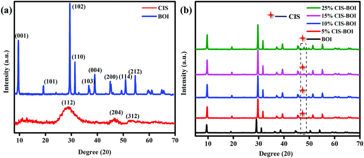 |
| | Fig. 1 PXRD patterns of (a) pristine CIS and BOI and (b) the CIS–BOI composites with varying CIS content. | |
Surface morphology analysis of pristine CIS, BOI and the 15% CIS–BOI composite material was carried out by field emission scanning electron microscopy (FESEM). It is obvious from Fig. 2(a) and (b) that pure BOI exhibits a plate-like morphology, whereas the pure CIS QDs have a particle-like appearance. Furthermore, Fig. 2(c) shows the arrangement of CIS and BOI units in an arbitrary fashion in the 15% CIS–BOI binary composite. The plate-like morphology of the BOI material supports more reaction active sites, which boosts its photocatalytic activity. Additionally, the energy dispersive X-ray (EDX) spectrum of the 15% CIS–BOI composite is shown in Fig. 2(d) and the spectra of the pristine materials (CIS and BOI) are shown in Fig. S1(a) and (b) (ESI†), which confirm the existence of elements such Bi, O, I, Cu, In, S in 15% CIS–BOI, and Bi, O, I in BOI, and Cu, In, S in CIS, showing good correlation with the XPS data. Furthermore, the elemental allocation was also confirmed from the elemental color-mapping of the 15% CIS–BOI composite, as depicted in Fig. S1(c)–(i) (ESI†).
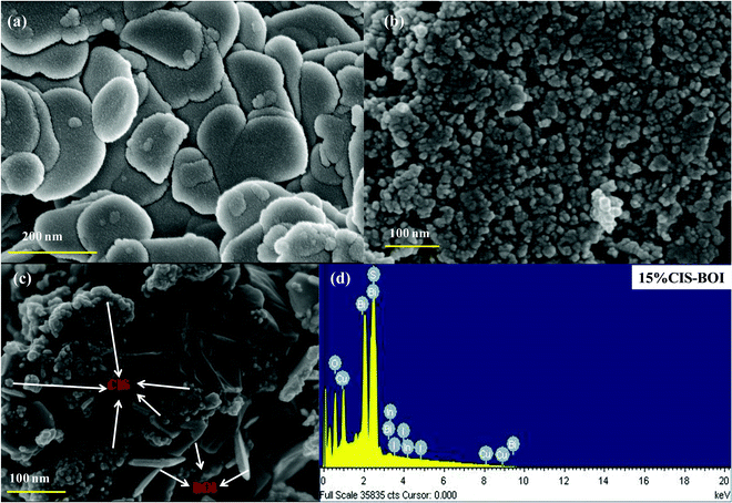 |
| | Fig. 2 FESEM images of (a) pristine BOI, (b) pristine CIS, and (c) the 15% CIS–BOI composite, and (d) the EDX spectrum of 15% CIS–BOI. | |
Furthermore, the morphological individuality, particle size of the ultra-small CIS QDs, the plate-like morphology of BOI and their homogeneous distribution in the 15% CIS–BOI composite were revealed by HRTEM analysis. Moreover, Fig. 3(a) presents the fringe pattern of the CIS QDs, which indicates that a single (112) chalcopyrite crystal plane with a d-spacing value of 0.32 nm shows good correlation with the PXRD analysis. Further, Fig. 3(b) shows the ultra-small dot-like structure of the CIS QDs with an average diameter of 3.89 nm, as shown in the particle-size distribution curve (inset in Fig. 3(b)), which exhibits a quantum confinement effect. In addition, Fig. 3(c) and (d) show the uniform distribution of the CIS QDs on the surface of the BOI MPs in the 15% CIS–BOI heterostructure. The selected area electron diffraction (SAED) image of the 15% CIS–BOI composite, as shown in Fig. 3(e), implies the attachment of CIS QDs (dark spots) on the surface of the BOI MPs (bright spots) in different crystalline phases, with the concentric circular pattern indicating the polycrystalline nature of the binary hybrid. Hence, the BOI MPs might be helpful in preventing aggregation and facilitating the homogeneous distribution of the CIS QDs. The fringe pattern visualized in the HRTEM image of CIS and BOI in the 15% CIS–BOI composite is shown in Fig. 3(f), where the dspacing value of 0.30 nm corresponds to the (102) crystal plane of the BOI MPs, whereas the lattice spacing of 0.32 nm represents the (112) plane of the CIS QDs, respectively. The minute particle size and crystallinity of the CIS QDs promotes fast charge-carrier diffusion from the bulk to the surface, which boosts photocatalytic activity. As a whole, it can be concluded that the CIS QDs were uniformly attached to the BOI surface, performing like clapboards in the separation of the CIS QDs and better supporting the material in the diffusion of the QDs.21 Additionally, they enhanced the surface to volume ratio, which increased the number of surface active sites, leading to better photocatalytic activity.
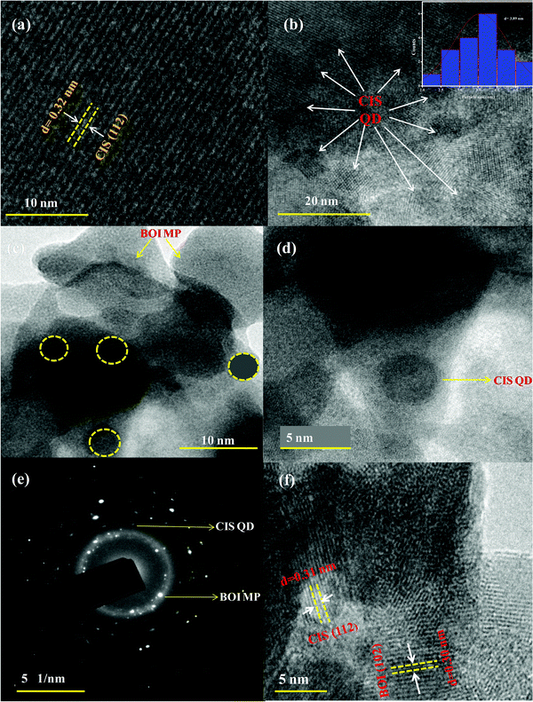 |
| | Fig. 3 HRTEM of the (a) fringe pattern of the CIS QDs, (b) image and size-distribution curve of the CIS QDs (inset), (c and d) deposition of the CIS QDs on the BOI MPs in the 15% CIS–BOI composite, (e) the SAED image of the 15% CIS–BOI composite, and (f) the fringe pattern of the 15% CIS–BOI composite. | |
The CIS–BOI heterostructure was measured by X-ray photoelectron spectroscopy (XPS) analysis. Fig. S2(a) (ESI†) shows the XPS survey spectrum of the 15% CIS–BOI heterojunction sample, which confirms the presence of Cu, In, S, Bi, O, I elements in the composite material and the absence of additional impurity peaks, in strong agreement with the EDX data. The acquired XPS results were plotted and deconvoluted using CASA-XPS. The atomic concentration ratios of Bi![[thin space (1/6-em)]](https://www.rsc.org/images/entities/char_2009.gif) :
:![[thin space (1/6-em)]](https://www.rsc.org/images/entities/char_2009.gif) O
O![[thin space (1/6-em)]](https://www.rsc.org/images/entities/char_2009.gif) :
:![[thin space (1/6-em)]](https://www.rsc.org/images/entities/char_2009.gif) I
I![[thin space (1/6-em)]](https://www.rsc.org/images/entities/char_2009.gif) :
:![[thin space (1/6-em)]](https://www.rsc.org/images/entities/char_2009.gif) Cu
Cu![[thin space (1/6-em)]](https://www.rsc.org/images/entities/char_2009.gif) :
:![[thin space (1/6-em)]](https://www.rsc.org/images/entities/char_2009.gif) In
In![[thin space (1/6-em)]](https://www.rsc.org/images/entities/char_2009.gif) :
:![[thin space (1/6-em)]](https://www.rsc.org/images/entities/char_2009.gif) S in the 15% CIS–BOI hybrid were found to be 9.19
S in the 15% CIS–BOI hybrid were found to be 9.19![[thin space (1/6-em)]](https://www.rsc.org/images/entities/char_2009.gif) :
:![[thin space (1/6-em)]](https://www.rsc.org/images/entities/char_2009.gif) 27.79
27.79![[thin space (1/6-em)]](https://www.rsc.org/images/entities/char_2009.gif) :
:![[thin space (1/6-em)]](https://www.rsc.org/images/entities/char_2009.gif) 2.92
2.92![[thin space (1/6-em)]](https://www.rsc.org/images/entities/char_2009.gif) :
:![[thin space (1/6-em)]](https://www.rsc.org/images/entities/char_2009.gif) 5.12
5.12![[thin space (1/6-em)]](https://www.rsc.org/images/entities/char_2009.gif) :
:![[thin space (1/6-em)]](https://www.rsc.org/images/entities/char_2009.gif) 5.21
5.21![[thin space (1/6-em)]](https://www.rsc.org/images/entities/char_2009.gif) :
:![[thin space (1/6-em)]](https://www.rsc.org/images/entities/char_2009.gif) 50.37. In Fig. 4(a), a doublet can be observed at binding energies of 159.2 and 164.4 eV, corresponding to Bi 4f5/2 and 4f7/2 spin states, respectively, for the pristine BOI MPs, indicating the trivalent oxidation state of Bi3+, where the peaks show blue shifting to 159.4 and 164.6 eV after the formation of the CIS–BOI heterojunction.34 Further, Fig. 4(b) shows three deconvoluted peaks for O 1s at 528.9, 531.4 and 532.6 eV, corresponding to lattice oxygen (OL), oxygen vacancies (OV) and chemi-absorbed/dissociated oxygen (OA), respectively, for pristine BOI.35 It was noticed that after the formation of the heterojunction, O shows XPS peaks at higher binding energies of 529.1, 531.6 and 532.8 eV. Moreover, the shifting of the Ov peak signifies the retaining of oxygen vacancies in the composite material, leading to efficient photocatalytic activity (good correlation with the Raman spectroscopy data). Similarly, the I 3d core level XPS spectra shows two high-resolution peaks at 618.7 and 630.2 eV for pristine BOI and 618.9 and 630.4 eV for the binary composite (Fig. 4(c)), which confirms the presence of I− ions in BOI.36 Further, Cu shows two peaks at 932.7 and 552.6 eV, which correspond to Cu 2p3/2 and Cu 2p1/2 spin states, respectively, indicating the existence of Cu+ ion in the CIS unit.37 However, after the formation of the heterojunction, peaks were shifted towards lower binding energies of 932.3 and 552.2 eV, respectively, as presented in Fig. 4(d). Additionally, Fig. 4(e) gives an idea on the XPS peaks of In 3d5/2 and In 3d3/2 at binding energies of 445.1 and 452.8 eV, respectively, proving the presence of In3+ in the pristine CIS QDs. However, in the 15% CIS–BOI binary hybrid, In shows red-shifting of its peaks at 444.6 and 552.6 eV, respectively. In addition, the appearance of two peaks at 158.6 and 164.0 eV for S 2p1/2 and 2p3/2, respectively, owing to spin–orbit coupling, validates the presence of S2− ions and the coordination of S to Cu and In in the CIS unit.38 However, after heterojunction formation, the 15% CIS–BOI shows red-shifting of the two peaks at 158.1 and 163.6 eV, as revealed in Fig. 4(f). A comparison between the binding energies of the constituting elements in the pristine and composite materials is given in Table S1 in the ESI.†
50.37. In Fig. 4(a), a doublet can be observed at binding energies of 159.2 and 164.4 eV, corresponding to Bi 4f5/2 and 4f7/2 spin states, respectively, for the pristine BOI MPs, indicating the trivalent oxidation state of Bi3+, where the peaks show blue shifting to 159.4 and 164.6 eV after the formation of the CIS–BOI heterojunction.34 Further, Fig. 4(b) shows three deconvoluted peaks for O 1s at 528.9, 531.4 and 532.6 eV, corresponding to lattice oxygen (OL), oxygen vacancies (OV) and chemi-absorbed/dissociated oxygen (OA), respectively, for pristine BOI.35 It was noticed that after the formation of the heterojunction, O shows XPS peaks at higher binding energies of 529.1, 531.6 and 532.8 eV. Moreover, the shifting of the Ov peak signifies the retaining of oxygen vacancies in the composite material, leading to efficient photocatalytic activity (good correlation with the Raman spectroscopy data). Similarly, the I 3d core level XPS spectra shows two high-resolution peaks at 618.7 and 630.2 eV for pristine BOI and 618.9 and 630.4 eV for the binary composite (Fig. 4(c)), which confirms the presence of I− ions in BOI.36 Further, Cu shows two peaks at 932.7 and 552.6 eV, which correspond to Cu 2p3/2 and Cu 2p1/2 spin states, respectively, indicating the existence of Cu+ ion in the CIS unit.37 However, after the formation of the heterojunction, peaks were shifted towards lower binding energies of 932.3 and 552.2 eV, respectively, as presented in Fig. 4(d). Additionally, Fig. 4(e) gives an idea on the XPS peaks of In 3d5/2 and In 3d3/2 at binding energies of 445.1 and 452.8 eV, respectively, proving the presence of In3+ in the pristine CIS QDs. However, in the 15% CIS–BOI binary hybrid, In shows red-shifting of its peaks at 444.6 and 552.6 eV, respectively. In addition, the appearance of two peaks at 158.6 and 164.0 eV for S 2p1/2 and 2p3/2, respectively, owing to spin–orbit coupling, validates the presence of S2− ions and the coordination of S to Cu and In in the CIS unit.38 However, after heterojunction formation, the 15% CIS–BOI shows red-shifting of the two peaks at 158.1 and 163.6 eV, as revealed in Fig. 4(f). A comparison between the binding energies of the constituting elements in the pristine and composite materials is given in Table S1 in the ESI.†
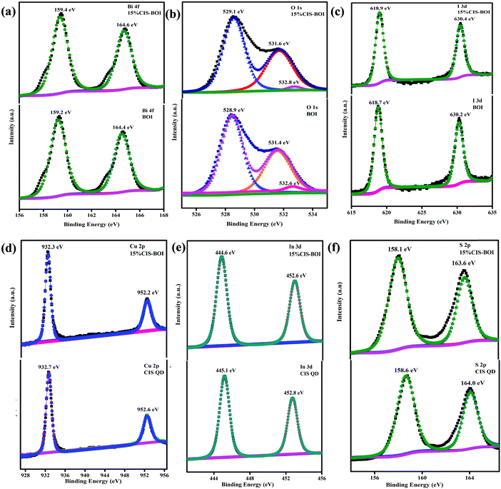 |
| | Fig. 4 XPS images of (a) Bi-4f, (b) O-1s, and (c) I-3d in pristine BOI and the 15% CIS–BOI composite; (d) Cu-2p, (e) In-3d, and (f) S-2p in pristine CIS and the 15% CIS–BOI composite. | |
From the data included in Table S1 (ESI†) it is clear that after the development of the CIS–BOI heterojunction, the BOI unit undergoes a blue-shifting in binding energy, whereas the CIS unit undergoes red-shifting in binding energy. These shifts in binding energy might be accredited to the partial transfer of electrons from the electron-rich BOI unit to the electron-deficient CIS unit, which increases the electron density at the CIS interface of the composite, affirming the decrease in the binding energy of the Cu, In, S elements. Likewise, the electron density of the BOI unit in the composite decreases compared with the pristine BOI, leading to an increase in the binding energy of the Bi, O, I elements. Hence, the variation in the chemical environment in the XPS data signifies the creation of a good built-in electric interface between the p-type BOI and n-type CIS, where electrons and holes can easily be separated. This also confirms the migration of electrons from BOI to CIS following Z-scheme charge transfer dynamics.39,40
To gain more evidence on the composite formation and presence of oxygen vacancies in the materials, Raman spectroscopy analysis was carried out under ambient conditions. From Fig. 5, two discrete Raman bands can be observed at 89 and 152 cm−1 for both pure BOI and the 15% CIS–BOI composite, corresponding to the A1g and E1g stretching modes of the Bi–I bond, respectively. However, no extra peaks were observed in the spectra of pristine BOI, which confirms its compositional purity (good fit to the PXRD data). Furthermore, the foremost peak intensity of the composite was weakened with a blue shift, as shown in the orange box in Fig. 5, which may be due to a change in the Bi–O environment.41 Additionally, the Raman band observed at around 89 cm−1 for pristine BOI and at a slight higher wavenumber for the composite correspond to oxygen defect sites.14 Moreover, the peaks at 294 and 335 cm−1 framed within the dotted line in Fig. 5 correspond to the A and E1LO/B12LO modes of the CuInS2 QDs.42 Hence, the results obtained from PXRD and Raman spectroscopy measurements strongly validate the formation of the BOI–CIS composite. In addition, it can be concluded that the oxygen vacancies in the pristine BOI are retained in the CIS–BOI composite and play a critical part in the catalytic mechanism.
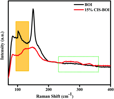 |
| | Fig. 5 Raman spectra of pristine BOI and the 15% CIS–BOI composite. | |
The optical properties of the as-prepared samples were analyzed by ultraviolet-visible-diffuse reflectance spectroscopy (UV-vis-DRS). Fig. 6(a) presents the optical absorbance spectra and band gap energy data of BOI, CIS, and the CIS–BOI nano-composites, which extend from the visible to near-IR region. Generally, the BOI sample shows a strong absorption spectrum, broadening up to 690 nm due to the presence of oxygen vacancies, which inherently boost the optical activity of the BOI MPs. Nevertheless, the optical absorption was further extended up to the near-IR region upon the in situ addition of the CIS unit in the CIS–BOI composites, indicating red-shifting of the material, which covers a wider spectral region compared to that of the pristine BOI MPs. The band gap energy may vary consequently according to the quantum confinement effect and oxygen vacancies of the materials.43 This inconsistency can be attributed to the extensive light absorption capacity of the CIS QDs. Hence, the composites utilize the entire visible region and some of the IR region, ensuring their improved optical response and higher photocatalytic activity compared to the pristine materials. In addition, the bandgap energies (E) of pristine CIS and BOI were calculated using eqn (1):
where
h is Planck's constant (6.626 × 10
−34 J s),
a denotes the absorption coefficient,
v is the frequency of light, and
A is the proportionality constant. Furthermore, the
n-value indicates the type of the electronic transition,
i.e.,
n = 1/2 indicates indirect and
n = 2 implies direct transitions.
22 However, in our case, pristine CIS shows a direct transition, whereas BOI shows an indirect transition, with band gap energies of 1.64 and 1.74 eV, respectively, as respectively shown in
Fig. 6(b) and (c). Moreover, it would be better for composite materials to have higher
Eg values compared to those of pristine materials, as this is favorable for an efficient photocatalytic reaction.
21
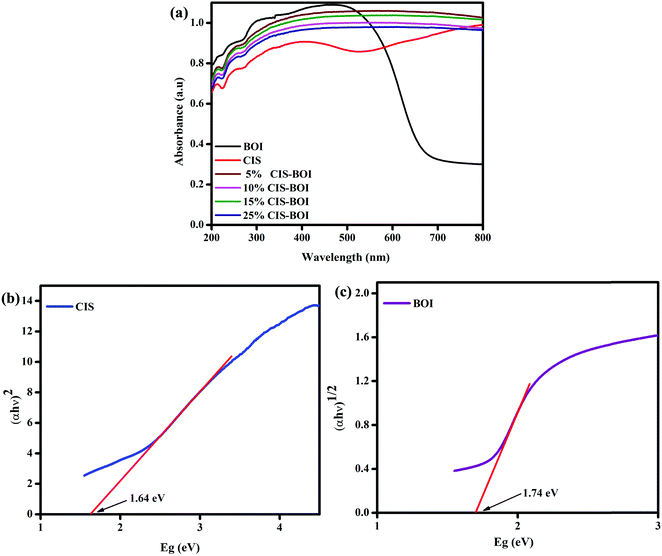 |
| | Fig. 6 (a) UV absorbance spectra of pristine BOI, CIS and varying weight% CIS–BOI composites; Tauc plots of (b) pristine CIS and (c) pristine BOI. | |
The photoluminescence (PL) spectra give information on the photogenerated charge carrier entrapping, transfer and recombination efficiency of the semiconductor materials. A highly intense peak signifies the fast recombination of electron–holes and a low intensity peak specifies good separation and slow recombination of electron–holes in a photocatalyst.25 Herewith, the pristine BOI shows a highly intense PL emission peak at around 490 nm (shown in Fig. S3, ESI†). Along with this, the pristine CIS QDs and all the CIS–BOI composites show PL emission peaks at a longer wavelength of 756 nm, as shown in Fig. 7. It can be observed from the plotted PL spectra that the 15% CIS–BOI composite exhibits the lowest intense peak of all the composites and both the pristine materials. Based upon the obtained PL spectra, the chronological order of charge-carrier recombination is CIS > 5% CIS–BOI > 10% CIS–BOI > 25% CIS–BOI > 15% CIS–BOI. Hence, the 15% CIS–BOI composite shows proficient exciton separation and transport ability via the proposed Z-scheme charge emigration pathway, resulting in an increase in the photocatalytic efficiency. The above results are in tune with the EIS and catalytic activity data.
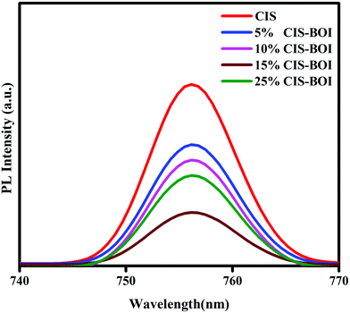 |
| | Fig. 7 PL emission spectra of pristine CIS and CIS–BOI composites with different wt% of CIS. | |
Electrochemical measurements
Electrochemical Mott–Schottky (MS) analysis was performed to determine the nature of the semiconductor catalyst (p- or n-type) and the flat-band potential (Efb) of the material. MS measurements of our prepared materials were conducted at frequencies of 500, 1000, and 1500 Hz. The CBM (conduction band minima) and VBM (valence band maxima) of CIS and BOI were calculated from the Efb values determined by MS analysis (Fig. 8(a) and (b)) according to eqn (2):| |  | (2) |
where the pH of the Na2SO4 electrolytic solution is 6.8 and the electrode potential at 25 °C of Ag/AgCl  is 0.198. It is noticed that the CIS QDs show a negative slope and BOI shows a positive slope, validating their n-type and p-type features, respectively. The Efb values of BOI and the CIS QDs vs. NHE were determined to be 2.22 and −0.95 eV, respectively. It has been reported in previous literature that the Efb value vs. NHE is around 0.1–0.3 eV below the CBM and above the VBM for n-type and p-type semiconductors, respectively.44,45 Hence, by altering the Efb values by 0.1 eV, the VB and CB positions of BOI and CIS were estimated to be 2.32 and −0.85 eV vs. NHE, respectively. Subsequently, the VB of CIS and CB of BOI were calculated to be 0.78 and 0.58 eV, respectively, by applying the following eqn (3):where the Eg values of BOI and CIS are 1.74 and 1.66 eV, respectively, as calculated from their Tauc plots (Fig. 6(b), (c)). Further the MS plot of the CIS–BOI composite (Fig. 8(c)) with an inverted V-shaped structure clearly divulged p–n heterojunction formation by the incorporation of p-BOI with n-CIS QD. Furthermore, it is noteworthy that the standard reduction potential
  and oxidation potential
  of water at pH 7 were −0.41 V and 1.99 V respectively.13,39 In that perspective, the higher positive VB value of BOI makes it a pertinent photocatalyst for O2 evolution and the more negative CB value of the CIS QDs makes it an efficient photocatalyst for H2 evolution. Nevertheless, the CIS QDs and BOI are incapable of the oxidation and reduction of water, respectively, authenticating that the oxidation reaction proceeds over the BOI surface, while the reduction reaction proceeds over the surface of the CIS QDs. Hence, enhanced photocatalytic activity is achieved owing to the charge separation promoted by the built-in electric field created at the p–n heterojunction.
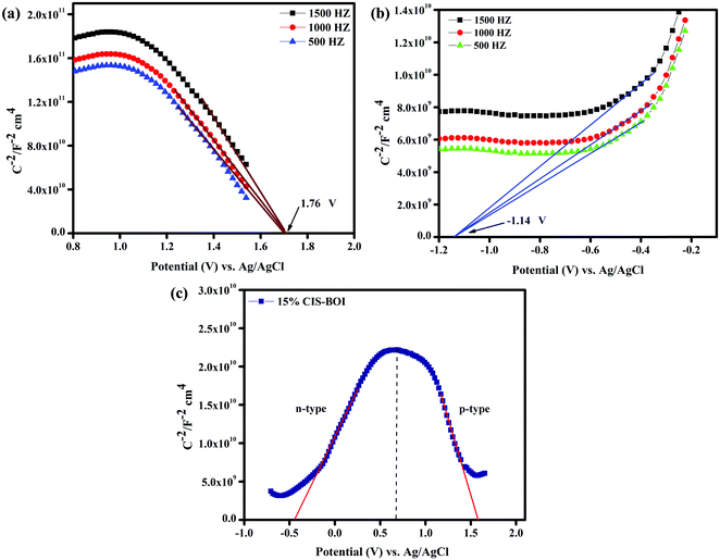 |
| | Fig. 8 MS plots of (a) pristine BOI, (b) pristine CIS at different frequencies, and (c) the 15% CIS–BOI composite. | |
Fig. 9 shows the linear sweep voltammetry (LSV) measurements of all of the prepared samples, which indicate the nature of the current (i.e. cathodic or anodic) and the bulkiness of the photo-excited electrons that are present on the surface of the semiconductor photocatalyst. It is notable that the photocatalytic activity can also be correlated with the photocurrent response of the semiconductor materials. The photocurrent density of the synthesized material under dark condition was quite negligible, while a high current density was observed under light irradiation. From Fig. 9(a) and (b), it was found that the CIS QDs show an anodic current of 0.13 mA cm−2, validating their n-type character, while the BOI MPs show a cathodic current of −0.66 mA cm−2, confirming their p-type character. In addition, the LSV plots of the composite materials (Fig. 9(c)) illustrate both cathodic and anodic current, implying that the binary hybrids exhibit both n- and p-type features. It is obvious from the figure that the CIS–BOI heterojunction composites exhibit a higher current than those of the pristine materials. However, 15% CIS–BOI shows the highest cathodic current of −4.15 mA cm−2 and anodic current of 3.95 mA cm−2 among all of the composite materials, with the photo-response of the materials following the order 15% CIS–BOI > 25% CIS–BOI > 10% CIS–BOI > 5% CIS–BOI. As a result, the 15% CIS–BOI binary hybrid shows the best photocatalytic activity of the synthesized composite materials.
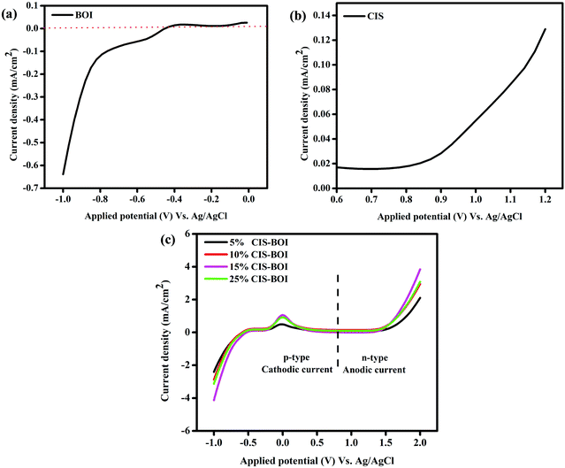 |
| | Fig. 9 LSV plots of (a) pristine BOI, (b) pristine CIS, and (c) CIS–BOI composites with varying wt% of CIS. | |
Electrochemical impedance spectroscopy (EIS) analysis predicts the resistance/conductance orientation about the electrolyte and electrode–electrolyte interface to gain insight into the kinetics of the photocatalytic reaction. Here, Fig. 10(a) shows Nyquist impedance plots under zero applied biasing conditions of all of the composites and pristine materials, where the fitted EIS circuit is shown as an inset in the figure. In the circuit, Rs, Rct, Ws, and C signify the electrolytic resistance, charge transfer resistance, Warburg impedance, and double layer capacitance, respectively. Additionally, the semicircle and straight line regions of the plots give information on the Rct and Warburg resistance, respectively, which indicate the efficiency of the material.46 The larger the semicircle diameter, the higher the interface resistance, leading to a lower conductance, and a smaller diameter indicates a lower Rct value, as obtained for the 15% CIS–BOI composite, as shown in Fig. 10(a).22 That means that the 15% CIS–BOI composite shows better charge separation and transport properties than all the other CIS–BOI composites and pristine materials, whereas pristine BOI shows the lowest charge separation, which is a good correlation to the PL analysis. The charge separation efficiency follows the order BOI < CIS < 5% CIS–BOI < 10% CIS–BOI < 25% CIS–BOI < 15% CIS–BOI, which confirms that low carrier recombination (obtained from PL) results in high photocurrent response.
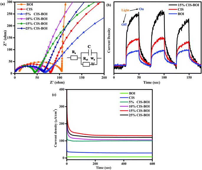 |
| | Fig. 10 (a) Nyquist impedance plots of pristine BOI, CIS and CIS–BOI composites with varying wt% of CIS, (b) TPC plots of pristine BOI, CIS, and the 15% CIS–BOI composite, and (c) CA plots of pristine BOI, CIS and CIS–BOI composites with varying wt% of CIS. | |
The transient photocurrent (TPC) indicates the exciton-separation efficiency of photo-induced charge-carriers. Current is produced due to the diffusion of photogenerated electrons and the photo-excited holes are consumed by the hole-acceptors in the electrocatalytic solution.32 Hence, from Fig. 10(b), it was observed that pristine CIS and BOI show inferior photocurrent densities compared with the binary hybrid owing to rapid exciton recombination (as can be well correlated to the PL and EIS data) and the 15% CIS–BOI composite shows superior photocurrent density leading to longer durability of photo-induced e−–h+ pairs at the heterojunction interface. Consequently, it can be deduced that the binary hybrid shows low charge-transfer resistance, resulting in high conductivity, thereby increasing its photocatalytic activity.
Chronoamperometry (CA) analysis was conducted to determine the stability of the photocatalyst under continuous light illumination. From Fig. 10(c), it is observable that all the synthesized materials are stable under visible-light illumination for a period of 600 s. It was noticed that the composite materials show greater current density than both the pristine BOI (5.5 μA cm−2) and CIS QDs (39.2 μA cm−2). Among all the composite materials, 15% CIS–BOI shows the highest current density of 148.1 μA cm−2, maintaining this value for a long period of time. Furthermore, the current density values follow the order: 15% CIS–BOI > 25% CIS–BOI > 10% CIS–BOI > 5% CIS–BOI > CIS > BOI at a steady applied voltage of 0.2 V. Hence, the best composite shows the highest photo-stability among all the other synthesized materials.
Photocatalytic water splitting
H2 evolution.
Photocatalytic hydrogen production capability measurements of the as-prepared photocatalysts were executed under a 125 W visible-light source using an aqueous solution of methanol as a hole scavenger. It was noted that no hydrogen gas was produced in the absence of catalyst as well as light, indicating the photocatalytic pathway. It is notable that the BOI MPs did not produce any hydrogen gas, as the CB potential (0.58 eV) is not sufficient for water reduction  . Nonetheless, the pristine CIS QDs achieved a hydrogen evolution rate of 231.92 μmol h−1, with an apparent conversion efficiency (ACE) of 3.72% (3.56 × 10¹⁶ no. of H2 molecules per s (theoretical calculation)). However, with the in situ introduction of just 5% CIS QDs on BOI, the resulting CIS–BOI composite showed an improved hydrogen evolution rate, which increased dramatically on further loading of CIS. The highest evolution rate of 615.5 μmol h−1 was observed for the 15% CIS–BOI heterojunction photocatalyst with an ACE of 9.84% (9.44 × 10¹⁶ no. of H2 molecules per s), which is almost 3 times higher than that of the pristine CIS QDs. This may be due to the Ov present in 2D BOI providing more surface active sites for enhancement of the photocatalytic reaction and effective exciton separation via the anticipated Z-scheme charge transfer dynamics. The rate of H2 evolution follows the order: 15% CIS–BOI > 25% CIS–BOI > 10% CIS–BOI > 5% CIS–BOI > CIS QD, as shown in Fig. 11(a). The lowest photocatalytic activity was observed for the 5% CIS–BOI hybrid, which can be attributed to lower exciton diffusion and migration as well as faster electron–hole recombination efficiency, authenticated from the photocurrent response, PL and EIS analysis. Further, it was observed that the photocatalytic activity gradually increased with the loading of CIS QDs to an optimum level and after that the evolution rate suddenly decreased upon the further loading of CIS. This may be due to the congestion of the 0D CIS QDs on the 2D BOI surface, which block the active sites of BOI and obstruct the absorption of light on its surface. This then reduces the density of photogenerated electrons, which are the foremost species in hydrogen generation. In addition, the best photocatalytic H2 evolution of the 15% CIS–BOI nanocomposite might be due to the greater absorption co-efficient of the CIS QDs, lower PL intensity and good composite formation. Furthermore, to ensure the robustness of the best hybrid in H2 generation, reusability analysis was conducted under identical reaction conditions and it was determined that the binary hybrid shows negligible reduction in evolution, even after 4 h of continuous runs, manifesting the durability of the material (Fig. 11(b)). Moreover, it was observed that the best photocatalyst shows no change in its PXRD peaks even after the activity study, which is shown in Fig. S4 (ESI†). Over and above that, a comparison is shown in Table S2 (ESI†), which provides evidence that the CIS–BOI heterojunction is a better catalyst amongst the other BOI-based photocatalysts for the H2 evolution reaction.
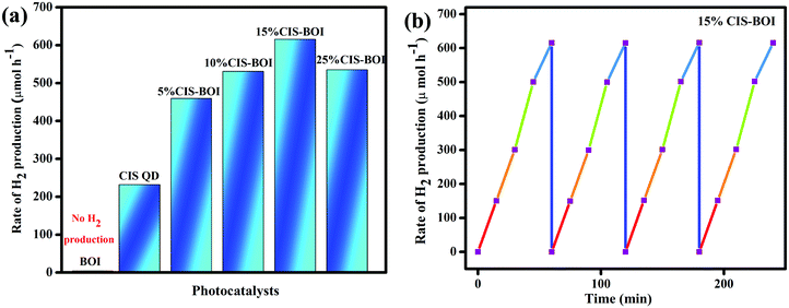 |
| | Fig. 11 (a) Rate of H2 production of pristine CIS, BOI and CIS–BOI composites with varying wt% of CIS; (b) reusability of the 15% CIS–BOI composite. | |
O2 evolution.
Further, the prepared samples (pristine and 15% CIS–BOI) were again examined in terms of their photocatalytic water oxidation under identical conditions using various electron scavengers, such as AgNO3 and FeCl3 solutions. As conferred earlier, no O2 evolution occurred in the absence of light as well as catalysts. We compared the pristine catalysts with our best material (15% CIS–BOI) and it was observed that the CIS QDs did not produce O2 gas, as the VB potential of the CIS QDs (0.78 eV) was found to not be appropriate for the water oxidation reaction (EH2O = 0.82 V vs. NHE at pH = 7). However, the rate of O2 production of pristine BOI was 191.3 μmol h−1, which is lower than that of our best catalyst, 15% CIS–BOI, which shows an O2 evolution velocity of 570.8 μmol h−1 in AgNO3 as a sacrificial reagent, as illustrated in Fig. 12(a). In addition, the best catalyst produces 8.76 × 10¹⁶ O2 molecules per s with an ACE of 9.16%, whereas pure BOI generates 2.93 × 10¹⁶ O2 molecules per s with an ACE of 3.06%, as theoretically calculated in the ESI.† It was observed that there were negligible changes in activity over 2 h and afterwards it decreased by a certain amount, as represented in Fig. 12(b). This might be due to the deposition of Ag particles from AgNO3 at the active sites of the catalyst, which slows further light absorption and loss of catalyst during filtration.30 Additionally, the best catalyst was again appraised for O2 production in the presence of an FeCl3 electron capturing agent and an O2 production rate of 498.7 μmol h−1 was observed, which is lower than in AgNO3 solution. This might be due to the fact that Ag+ from AgNO3 prevents the generation of durable photo-excited electrons via oxidative quenching.47 A comparison table is given in the ESI† (Table S2), which provides evidence that 15% CIS–BOI is an efficient photocatalyst for use in O2 evolution.
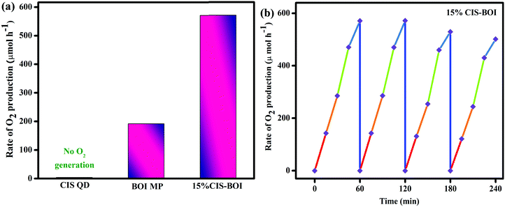 |
| | Fig. 12 (a) Rate of O2 production of pristine CIS, BOI and the 15% CIS–BOI hybrid; (b) reusability of the 15% CIS–BOI hybrid. | |
Possible photocatalytic mechanism towards H2 and O2 generation
Based on the above data analysis, the superior photocatalytic competence of the 15% CIS–BOI binary hybrid may be attributed to the synergistic effect between pristine BOI and the CIS QDs that creates a heterojunction at the interface and exciton migration through a Z-scheme mode.48 It is observable from the MS data that the bandgap arrangement of the pristine BOI and CIS QD photocatalysts is positioned in a heterojunction fashion, as shown in Scheme 1, and that the mechanism may proceed via two different pathways: (i) double-charge pathway: under the irradiation of visible light of λ > 420 nm, where the semiconductors are excited to generate electron–hole (e−–h+) pairs, which afterwards are separated and the photogenerated e− from the more negative CB of photosystem-1 migrate to the subordinate CB of photosystem-2. Meanwhile, the excited h+ migrate from the higher VB to the lower VB potential in a recurring manner; and (ii) a direct/mediator free Z-scheme pathway: where photo-excited e− from the CB of one system combine with the h+ in the VB of the other system with no mediator support. In depth, if the photo-excited charge-carriers migrate in the former pathway as represented in Scheme 1(a), from the higher CB of the CIS QDs, the photogenerated e− migrate towards the lower CB of BOI, and simultaneously the photogenerated holes from the higher VB of BOI move towards the lower VB of CIS. As a result, the e− density at the CB of BOI increases and the water reduction reaction must take place at the CB of BOI. Unfortunately, this cannot happen as the required CB potential for water reduction is not suitable in the case of BOI, hence meaning that water reduction could not take place via a double-charge pathway. Also, enhanced photocatalytic H2 reduction activity was observed for the 15% CIS–BOI composite compared with pristine CIS, meaning that the photo-excited e−–h+ migration follows the latter pathway, i.e., the Z-scheme dynamics presented in Scheme 1(b). In brief, the gathered electrons from the CB of BOI transferred to the VB of the CIS QDs via the heterojunction edge and recombined via band bending, fixed electric potential, and coulombic forces. Accordingly, the recombination of excitons took place via rapid charge-carrier separation from the VB of BOI and the CB of the CIS QDs, with the heterojunction edge acting as the recombination center of the e−–h+ pair.22 In the meantime, the h+ on BOI are consumed by the methanol sacrificial agent and the accumulated e− on the CIS QDs reduce the H2O molecules to produce H2 molecules49via the following stepwise reaction mechanism:
| CIS + hν → [e−CB]CIS + [h+VB]CIS |
| BOI + hν → [e−CB]BOI + [h+VB]BOI |
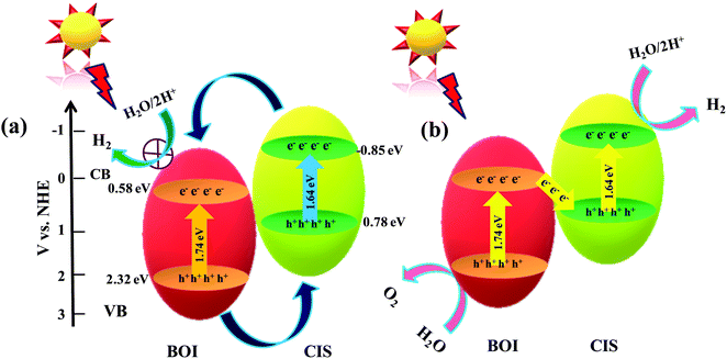 |
| | Scheme 1 Anticipated charge-transfer mechanism over the CIS–BOI binary hybrid photocatalyst under the illumination of visible light via (a) double charge and (b) Z-scheme charge-transfer pathways. | |
Moreover, the accumulated photoelectrons on the CB of the CIS QDs and the holes on the VB of BOI are poised to aid in the reduction and oxidation of water, respectively, as the potential energies of the CB and VB are appropriate for water splitting. Hence, the 15% CIS–BOI hybrid is an efficient photocatalyst for water oxidation as well as reduction, as it exhibits excellent carrier-separation and migration ability. In addition, higher O2 evolution activity was observed for the 15% CIS–BOI hybrid in the presence of AgNO3 solution, where Ag+ acts as an electron scavenger and reduces to Ag0.50 Meanwhile, photo-excited holes on the VB of BOI approach water molecules to produce O2 gas via the following stepwise below:
Anticipated theoretical approach of O2 generation
It is known that the chemistry of the O2 generation pathway is pretty complex to portray, however considering the ideas and science from the reported literature, the mechanism might be outlined toward water-oxidation reaction on an Ov-rich BOI interface.51,52 In this regard, two ways of forming O![[double bond, length as m-dash]](https://www.rsc.org/images/entities/char_e001.gif) O bonds are considered: (a) H2O breaks into H and OH and this OH couples with the oxygen of another water molecule to form OOH.
O bonds are considered: (a) H2O breaks into H and OH and this OH couples with the oxygen of another water molecule to form OOH.
(b) H2O molecules combine with H and OH to form HOOH.
| i.e. H2O + H + OH → HOOH + 2H |
Here, pathway (b) is the least likely as it proceeds via a higher activation energy (Ea) hurdle. As a result, the feasible reaction mechanism follows the OOH intermediate pathway that has a lower Ea, where the O2 evolution takes place over the Ov-rich BOI interface as follows. The generated OOH combines with defective BOI that has a low Ea barrier and the formation of O![[double bond, length as m-dash]](https://www.rsc.org/images/entities/char_e001.gif) O is the rate-determining-step in the water oxidation reaction. For this reason, the water-oxidation reaction is likely to be more kinetically feasible over Ov-rich BOI.
O is the rate-determining-step in the water oxidation reaction. For this reason, the water-oxidation reaction is likely to be more kinetically feasible over Ov-rich BOI.
Radical trapping experiments
Therefore, the direct Z-scheme pathway enhances exciton separation and the transfer route, which boosts the photocatalytic efficiency. In addition, to verify the foundation of the Z-scheme charge migration mechanism, nitro blue tetrazolium chloride (NBT) testing and terephthalic acid (TA) analysis were performed by taking 5 × 10⁻⁵ M aqueous NBT solution and 5 × 10⁻⁴ M aqueous TA solution as well as the pristine materials (BOI and CIS QDs) and our best binary hybrid (15% CIS–BOI) to ensure their ability to generate superoxide (˙O2−) and hydroxyl (OH˙) radicals according to our previous reports.25,28 In general, the standard reduction potential of O2 → ˙O2− is −0.33 eV vs. NHE. Thus, the BOI MPs did not produce any superoxide radicals even though their CB has a positive value (+0.58 eV). Nonetheless, ˙O2− species formation was observed for the CIS QDs since their CB has a negative value (−0.85 eV). Similarly, the 15% CIS–BOI binary hybrid exhibited an absorbance wavelength at 258 nm in the NBT spectral study, validating the transformation of oxygen molecules to superoxide radicals, which occurs on the surface of the CIS part of the binary hybrid and confirms that the e−–h+ migration between the VB and CB of the combined units does not proceed via the double-charge pathway but instead proceeds more readily via the anticipated direct Z-scheme pathway. Moreover, the reduction in the NBT absorption intensity corresponds to the degradation of the NBT fraction by the generated superoxide radicals. Further, it was noticed that the 15% CIS–BOI hybrid shows a decrease in its UV spectral intensity compared to that of the pristine CIS QDs at an absorption wavelength of 260 nm, which implies that agglomeration of the photogenerated electrons on the CIS QD unit of the hybrid occurs, endorsing the successful reduction of O2 → ˙O2−, as represented in Fig. 13(a). Likewise, the standard oxidation potential of OH− → ˙OH is around +1.99 eV vs. NHE. Accordingly, the CIS QDs did not generate ˙OH radicals as their VB potential was positioned at around 1.23 eV, whereas ˙OH radical formation was observable in the case of BOI even though its VB edge is located at around 2.31 eV. In the performed TA tests, the 15% CIS–BOI heterostructure shows an emission spectrum at around 423 nm, as shown in Fig. 13(b). At the time of TA spectral analysis, ˙OH radical formation took place on the BOI surface and not on the CIS surface. Additionally, it is noticeable that an increase in PL intensity can be observed for the 15% CIS–BOI hybrid, signifying the gathering of holes on the VB of the BOI unit, which indicates more ˙OH radical generation by the successful oxidation of OH− ions. The above analysis confirmed that the charge transfer is carried out via a Z-scheme pathway rather than a double charge mechanism.
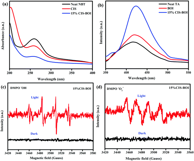 |
| | Fig. 13 (a) UV-vis spectra of pristine NBT, CIS, and CIS–BOI, and (b) PL spectra of pristine TA, BOI, and CIS–BOI. EPR spectra of 15% CIS–BOI under dark and light conditions: (c) DMPO–˙O2− in methanol solution and (d) DMPO–˙OH in water. | |
Further, to confirm Z-scheme charge transfer dynamics, a powerful tool, i.e. DMPO (5,5-dimethyl-1-pyrroline-N-oxide) trapping EPR (electron paramagnetic resonance) analysis, was carried out to identify the formation of short-lived ˙OH and ˙O2− radicals under dark and visible-light irradiation. As visualized in Fig. 13(c) and (d), no signal coupled with DMPO–˙OH and DMPO–˙O2− was identified under dark conditions. Nevertheless, under visible-light illumination, EPR signals were observed for DMPO–˙O2− and DMPO–˙OH. The above results reveal the formation of ˙OH and ˙O2− radicals on the CIS–BOI hybrid (in good correlation with the TA and NBT analysis). Since the CB of CIS (−0.85 eV) is suitable for overcoming the reduction potential of O2 → ˙O2− (−0.33 eV vs. NHE), superoxide radical formation must take place on the CIS unit and the VB of BOI (2.31 eV) to conquer the oxidation potential of OH− → ˙OH (+1.99 eV vs. NHE), with hydroxyl radical formation occurring on the BOI surface of the composite hybrid. Based on the above results, it was found that the charge separation and migration on the 15% CIS–BOI photocatalyst does not follow a typical double charge pathway, rather it follows direct-Z-scheme charge dynamics.
Superiority of oxygen vacancies (Ov)
Oxygen vacancies play a great role in charge carrier separation, which enhances the photocatalytic reaction drastically. In brief, to establish Ov and their significance in exciton separation, Raman spectroscopy, EIS, and XPS analysis were carried out and it was confirmed from those analyses that oxygen vacancies are also present in the designed binary hybrid. In addition, the durability of the e−–h+ pairs substantially depends on the creation of defects as well as the band structure of the material. It is notable that vacancies are such species, that if present in a huge quantity, lead to faster e−–h+ recombination and if are present in a negligible amount, effective e−–h+ separation is inhibited, with low photocatalytic activity being exhibited.53 Therefore, Ov in a restricted amount are useful for trapping holes, leading to better e−–h+ separation, which yields superior photocatalytic activity. Moreover, the obtained data from XPS and Raman spectroscopy analyses confirm the presence of Ov in the binary composite (15% CIS–BOI) and from PL and EIS data it is quite obvious that the hybrid shows superior charge carrier separation, resulting in its effective activity. In short, the Ov zone provides a high electron concentration, which is fruitful for the water-reduction reaction, ensuring efficient H2 evolution. Additionally, the Ov region traps photo-induced electrons due to the availability of holes on the catalytic surface, which is productive for the water-oxidation reaction, triggering effectual O2 generation. Further, these defect sites encourage water oxidation reaction via triggering atomic oxygen intermediate formation via a low activation energy barrier. In brief, a H2O molecule is first adsorbed at a vacancy site, followed by an exothermic and very low energy barrier oriented O–H bond breaking step that produces OH and H, whereafter the OH cleaves into O and H via another low activation energy and endothermic pathway. However, this OH breaking step over defect free materials is reversible in nature, regenerating OH species, which although feasible from a free energy perspective, in a defect/vacancy oriented system this reversibility is hindered due to the strong attachment of H and O.48 The above discussed chemistry provides a theoretical insight into Ov and O2 evolution. Therefore, Ov are really useful species for enhancing photocatalytic activity.
Conclusions
In conclusion, we have established an efficient co-catalyst free 0D/2D binary hybrid with highly reducing and oxidizing exciton availability; improved light absorption capacity; and effective charge separation efficiency, synthesized via an in situ reflux method. Promoted by the admirable light harvesting properties of the CIS QDs, the as-synthesized CIS–BOI binary hybrids were found to be competent photocatalysts for visible-light driven O2 and H2 production compared to their pristine counterparts. Furthermore, the 15% binary hybrid shows optimal H2 and O2 evolution rates, with ACE values of 9.84% and 9.16% at 420 nm, respectively. PXRD and XPS measurements confirmed the strong interaction between the CIS and BOI units, and PL, EIS and photocurrent measurements supported effective charge carrier separation of the binary hybrids. Moreover, the highly reducing photo-induced electrons on the CIS surface and highly oxidizing photogenerated holes in the VB of BOI of the 15% CIS–BOI composite via A solid mediator-free Z-scheme pathway brought about a significant improvement in water reduction and oxidation performance respectively. Furthermore, Ov play an important role in charge separation and substrate activation, thereby increasing the effectiveness of the water redox reactions. Hence, this study provides new insight on the design and development of direct Z-scheme based photocatalyst that is active over the visible to near-IR regions for H2 and O2 generation in an eco-friendly manner.
Conflicts of interest
The authors declare no competing financial interests.
Acknowledgements
The authors express their profound gratitude toward Siksha ‘O’ Anusandhan Deemed to be University for providing all of the necessary facilities and financial support to carry out this research work.
References
- K. O. Joanna and H. Weller, ACS Appl. Mater. Interfaces, 2013, 5, 12221–12237 CrossRef PubMed.
- D. Prusty, L. Paramanik and K. M. Parida, Energy Fuels, 2021, 35, 4670–4686 CrossRef CAS.
- C. L. Wang and D. Astruc, Chem. Soc. Rev., 2014, 43, 7188–7216 RSC.
- Z. Long, W. Zhang, J. Tian, G. Chen, Y. Liu and R. Liu, Inorg. Chem. Front., 2021, 8, 880–897 RSC.
- B. Tahir and M. Tahir, Appl. Surf. Sci., 2020, 506, 145034 CrossRef CAS.
- M. Umer, M. Tahir, M. U. Azam, B. Tahir and M. Musaab, Int. J. Hydrogen Energy, 2019, 44, 13466–13479 CrossRef CAS.
- R. Xie, M. Rutherford and X. Peng, J. Am. Chem. Soc., 2009, 131, 5691–5697 CrossRef CAS PubMed.
- C. Xia, J. D. Meeldijk, H. C. Gerritsen and C. M. Donega, Chem. Mater., 2017, 29, 4940–4951 CrossRef CAS PubMed.
- Y. Yuan, G. Fang, D. Chen, Y. Huang and L. Yang,
et al.
, Dalton Trans., 2018, 47, 5652–5659 RSC.
- Y.-J. Yuan, D.-Q. Chen, Y.-W. Huang, Z.-T. Yu and J.-S. Zhong,
et al.
, ChemSusChem, 2016, 9, 1003–1009 CrossRef CAS PubMed.
- H. Cheng, B. Huang and B. Y. Dai, Nanoscale, 2014, 6, 2009 RSC.
- X. Zhang, H. Yang, B. Zhang, Y. Shen and M. Wang, Adv. Mater. Interfaces, 2016, 3, 1500273 CrossRef.
- T.-H. Chen, M. Yoshida, S. Tsunekawa and J.-H. Wu,
et al.
, Catal. Sci. Technol., 2020, 10, 3223–3231 RSC.
- M. Ji, R. Chen, J. Di, Y. Liu, K. Li, Z. Chen, J. Xia and H. Li, J. Colloid Interface Sci., 2019, 533, 612–620 CrossRef CAS PubMed.
- J. An, Y. Du, T. Wang, C. Wang, W. Hao and J. Zhang, Rare Met., 2008, 27, 243–250 CrossRef.
- G. J. Lee, Y. C. Zheng and J. J. Wu, Catal. Today, 2018, 307, 197–204 CrossRef CAS.
- L. Ye, Y. Su, X. Jin, H. Xie and F. Cao, Appl. Surf. Sci., 2014, 311, 858–863 CrossRef CAS.
- X. Zhang, L. Z. Zhang, T. F. Xie and D. J. Wang, J. Phys. Chem. C, 2009, 113, 7371–7378 CrossRef CAS.
- J. Liu, M.-J. Chang and H. L. Du, J. Nanosci. Nanotechnol., 2017, 17, 3792–3797 CrossRef CAS.
- K. H. Reddy, S. Martha and K. Parida, Inorg. Chem., 2013, 52, 6390–6401 CrossRef CAS PubMed.
- D. Kandi, S. Martha, A. Thirumurugan and K. M. Parida, J. Phys. Chem. C, 2017, 121, 4834–4849 CrossRef CAS.
- D. Prusty, S. Mansingh, L. Acharya, L. Paramanik and K. M. Parida, RSC Adv., 2022, 12, 1265 RSC.
- T. B. Li, G. Chen, C. Zhou, Z. Y. Shen, R. C. Jin and J. X. Sun, Dalton Trans., 2011, 40, 6751–6758 RSC.
- J. Yu, S. Wang, J. Low and W. Xiao, Phys. Chem. Chem. Phys., 2013, 15, 16883–16890 RSC.
- D. Kandi, D. P. Sahoo, S. Martha and K. M. Parida, Adv. Mater. Interfaces, 2019, 6, 1900370 CrossRef.
- S. Tasleem, M. Tahir and Z. Y. Zakaria, J. Alloys Compd., 2020, 842, 155752 CrossRef CAS.
- N. Fajrina and M. Tahir, Chem. Eng. J., 2019, 374, 1076–1095 CrossRef CAS.
- S. Subudhi, S. Mansingh, G. Swain, A. Behera, D. Rath and K. M. Parida, Inorg. Chem., 2019, 58, 4921–4934 CrossRef CAS PubMed.
- M. Tahir, Int. J. Hydrogen Energy, 2017, 42, 28309–28326 CrossRef CAS.
- S. Sultana, S. Mansingh and K. M. Parida, J. Phys. Chem. C, 2018, 122, 808–819 CrossRef CAS.
- S. Nayak, G. Swain and K. M. Parida, ACS Appl. Mater. Interfaces, 2019, 11, 20923–20942 CrossRef CAS PubMed.
- A. Behera, P. Babu and K. Parida, Inorg. Chem. Front., 2021, 8, 1489–1499 RSC.
- J. T. Muldar, N. Kirkwood, L. D. Trizio, C. Li, S. Bals, L. Manna and A. Houtepen, ACS Appl. Nano Mater., 2020, 3, 3859–3867 CrossRef PubMed.
- T. B. Li, G. Chen, C. Zhou, Z. Y. Shen, R. C. Jin and J. X. Sun, Dalton Trans., 2011, 40, 6751–6758 RSC.
- M. J. Islam, D. A. Reddy, N. S. Han, J. Choi, J. K. Song and T. K. Kim, Phys. Chem. Chem. Phys., 2016, 18, 24984–24993 RSC.
- Y. Huang, H. Li, M. S. Balogun, W. Liu, Y. Tong, X. Lu and H. Ji, ACS Appl. Mater. Interfaces, 2014, 6, 22920–22927 CrossRef CAS PubMed.
- Z. Guan, J. Pan, Q. Li, G. Li and J. Yang, ACS Sustainable Chem. Eng., 2019, 7, 7736–7742 CrossRef CAS.
- Q. Wang, W. Wang, L. Zhong, S. Liu, X. Cao and F. Cui, Appl. Catal., B, 2018, 220, 290–302 CrossRef CAS.
- G. Swain, S. Sultana and K. M. Parida, ACS Sustainable Chem. Eng., 2020, 8, 4848–4862 CrossRef CAS.
- Y. Guo, Y. Ao, P. Wang and C. Wang, Appl. Catal., B, 2019, 254, 479–490 CrossRef CAS.
- P. Wu, L. Feng, Y. Liang, X. Zhang, X. Li, S. Tian, H. Hu and G. Yin,
et al.
, J. Mater. Sci.: Mater. Electron., 2020, 31, 5385–5401 CrossRef CAS.
- C. Buchmaier, T. Rath, F. Pirolt, A. Knall, P. Kaschnitz, O. Glatter, K. Wewerka, F. Hofer, B. Kunert, K. Krenn and G. Trimmel, RSC Adv., 2016, 6, 106120–106129 RSC.
- J. Jiang, X. Zhang, P. Sun and L. Zhang, J. Phys. Chem. C, 2011, 115, 20555–20564 CrossRef CAS.
- S. Chen, Y. Hu, L. Ji, X. Jiang and X. Fu, Appl. Surf. Sci., 2014, 292, 357–366 CrossRef CAS.
- X. Gao, Y. Shang, L. Liu and F. J. Fu, J. Catal., 2019, 371, 71–80 CrossRef CAS.
- G. Swain, S. Sultana, J. Moma and K. M. Parida, Inorg. Chem., 2018, 57, 10059–10071 CrossRef CAS PubMed.
- R. S. Sprick, Z. Chen, A. J. Cowan, Y. Bai, C. M. Aitchison, Y. Fang and M. A. Zwijnenburg,
et al.
, Angew. Chem., Int. Ed., 2020, 59, 18695–18700 CrossRef CAS PubMed.
- S. Mansingh, D. Kandi, K. K. Das and K. Parida, ACS Omega, 2020, 5, 9789–9805 CrossRef CAS PubMed.
- S. Mansingh, D. K. Padhi and K. M. Parida, Int. J. Hydrogen Energy, 2016, 41, 14133–14146 CrossRef CAS.
- I. Ivanova, T. A. Kandiel, Y. J. Cho, W. Choi and D. Bahnemann, ACS Catal., 2018, 8, 2313–2325 CrossRef CAS.
- I. Funes-Ardoiz, P. Garrido-Barros, A. Llobet and F. Maseras, ACS Catal., 2017, 7, 1712–1719 CrossRef CAS.
- S. Lin, X. Ye, X. Gao and J. Huang, J. Mol. Catal. A: Chem., 2015, 406, 137–144 CrossRef CAS.
- Y. C. Zhang, Z. Li, L. Zhang, L. Pan, X. Zhang, L. Wang, F. E. Aleem and J. J. Zou, Appl. Catal., B, 2018, 224, 101–108 CrossRef CAS.
Footnote |
| † Electronic supplementary information (ESI) available: It is available, which contains the chemical information, synthetic methods, synthetic scheme, details on the characterization techniques, fabrication of the working electrodes, EDX patterns of pristine CIS and BOI, color-mapping image of the 15% CIS–BOI hybrid, XPS survey of the 15% CIS–BOI composite, binding energy comparison table, PL of pristine BOI, calculation of ACE and the no. of H2 and O2 molecules of the 15% CIS–BOI composite and pristine CIS and BOI. A comparison table is given for photocatalytic H2 and O2 production and PXRD analysis of the 15% CIS–BOI composite before and after use. See DOI: https://doi.org/10.1039/d2ya00046f |
|
| This journal is © The Royal Society of Chemistry 2022 |
Click here to see how this site uses Cookies. View our privacy policy here.  Open Access Article
 and
K. M.
Parida
 *
*


![[thin space (1/6-em)]](https://www.rsc.org/images/entities/char_2009.gif) :
:![[thin space (1/6-em)]](https://www.rsc.org/images/entities/char_2009.gif) O
O![[thin space (1/6-em)]](https://www.rsc.org/images/entities/char_2009.gif) :
:![[thin space (1/6-em)]](https://www.rsc.org/images/entities/char_2009.gif) I
I![[thin space (1/6-em)]](https://www.rsc.org/images/entities/char_2009.gif) :
:![[thin space (1/6-em)]](https://www.rsc.org/images/entities/char_2009.gif) Cu
Cu![[thin space (1/6-em)]](https://www.rsc.org/images/entities/char_2009.gif) :
:![[thin space (1/6-em)]](https://www.rsc.org/images/entities/char_2009.gif) In
In![[thin space (1/6-em)]](https://www.rsc.org/images/entities/char_2009.gif) :
:![[thin space (1/6-em)]](https://www.rsc.org/images/entities/char_2009.gif) S in the 15% CIS–BOI hybrid were found to be 9.19
S in the 15% CIS–BOI hybrid were found to be 9.19![[thin space (1/6-em)]](https://www.rsc.org/images/entities/char_2009.gif) :
:![[thin space (1/6-em)]](https://www.rsc.org/images/entities/char_2009.gif) 27.79
27.79![[thin space (1/6-em)]](https://www.rsc.org/images/entities/char_2009.gif) :
:![[thin space (1/6-em)]](https://www.rsc.org/images/entities/char_2009.gif) 2.92
2.92![[thin space (1/6-em)]](https://www.rsc.org/images/entities/char_2009.gif) :
:![[thin space (1/6-em)]](https://www.rsc.org/images/entities/char_2009.gif) 5.12
5.12![[thin space (1/6-em)]](https://www.rsc.org/images/entities/char_2009.gif) :
:![[thin space (1/6-em)]](https://www.rsc.org/images/entities/char_2009.gif) 5.21
5.21![[thin space (1/6-em)]](https://www.rsc.org/images/entities/char_2009.gif) :
:![[thin space (1/6-em)]](https://www.rsc.org/images/entities/char_2009.gif) 50.37. In Fig. 4(a), a doublet can be observed at binding energies of 159.2 and 164.4 eV, corresponding to Bi 4f5/2 and 4f7/2 spin states, respectively, for the pristine BOI MPs, indicating the trivalent oxidation state of Bi3+, where the peaks show blue shifting to 159.4 and 164.6 eV after the formation of the CIS–BOI heterojunction.34 Further, Fig. 4(b) shows three deconvoluted peaks for O 1s at 528.9, 531.4 and 532.6 eV, corresponding to lattice oxygen (OL), oxygen vacancies (OV) and chemi-absorbed/dissociated oxygen (OA), respectively, for pristine BOI.35 It was noticed that after the formation of the heterojunction, O shows XPS peaks at higher binding energies of 529.1, 531.6 and 532.8 eV. Moreover, the shifting of the Ov peak signifies the retaining of oxygen vacancies in the composite material, leading to efficient photocatalytic activity (good correlation with the Raman spectroscopy data). Similarly, the I 3d core level XPS spectra shows two high-resolution peaks at 618.7 and 630.2 eV for pristine BOI and 618.9 and 630.4 eV for the binary composite (Fig. 4(c)), which confirms the presence of I− ions in BOI.36 Further, Cu shows two peaks at 932.7 and 552.6 eV, which correspond to Cu 2p3/2 and Cu 2p1/2 spin states, respectively, indicating the existence of Cu+ ion in the CIS unit.37 However, after the formation of the heterojunction, peaks were shifted towards lower binding energies of 932.3 and 552.2 eV, respectively, as presented in Fig. 4(d). Additionally, Fig. 4(e) gives an idea on the XPS peaks of In 3d5/2 and In 3d3/2 at binding energies of 445.1 and 452.8 eV, respectively, proving the presence of In3+ in the pristine CIS QDs. However, in the 15% CIS–BOI binary hybrid, In shows red-shifting of its peaks at 444.6 and 552.6 eV, respectively. In addition, the appearance of two peaks at 158.6 and 164.0 eV for S 2p1/2 and 2p3/2, respectively, owing to spin–orbit coupling, validates the presence of S2− ions and the coordination of S to Cu and In in the CIS unit.38 However, after heterojunction formation, the 15% CIS–BOI shows red-shifting of the two peaks at 158.1 and 163.6 eV, as revealed in Fig. 4(f). A comparison between the binding energies of the constituting elements in the pristine and composite materials is given in Table S1 in the ESI.†
50.37. In Fig. 4(a), a doublet can be observed at binding energies of 159.2 and 164.4 eV, corresponding to Bi 4f5/2 and 4f7/2 spin states, respectively, for the pristine BOI MPs, indicating the trivalent oxidation state of Bi3+, where the peaks show blue shifting to 159.4 and 164.6 eV after the formation of the CIS–BOI heterojunction.34 Further, Fig. 4(b) shows three deconvoluted peaks for O 1s at 528.9, 531.4 and 532.6 eV, corresponding to lattice oxygen (OL), oxygen vacancies (OV) and chemi-absorbed/dissociated oxygen (OA), respectively, for pristine BOI.35 It was noticed that after the formation of the heterojunction, O shows XPS peaks at higher binding energies of 529.1, 531.6 and 532.8 eV. Moreover, the shifting of the Ov peak signifies the retaining of oxygen vacancies in the composite material, leading to efficient photocatalytic activity (good correlation with the Raman spectroscopy data). Similarly, the I 3d core level XPS spectra shows two high-resolution peaks at 618.7 and 630.2 eV for pristine BOI and 618.9 and 630.4 eV for the binary composite (Fig. 4(c)), which confirms the presence of I− ions in BOI.36 Further, Cu shows two peaks at 932.7 and 552.6 eV, which correspond to Cu 2p3/2 and Cu 2p1/2 spin states, respectively, indicating the existence of Cu+ ion in the CIS unit.37 However, after the formation of the heterojunction, peaks were shifted towards lower binding energies of 932.3 and 552.2 eV, respectively, as presented in Fig. 4(d). Additionally, Fig. 4(e) gives an idea on the XPS peaks of In 3d5/2 and In 3d3/2 at binding energies of 445.1 and 452.8 eV, respectively, proving the presence of In3+ in the pristine CIS QDs. However, in the 15% CIS–BOI binary hybrid, In shows red-shifting of its peaks at 444.6 and 552.6 eV, respectively. In addition, the appearance of two peaks at 158.6 and 164.0 eV for S 2p1/2 and 2p3/2, respectively, owing to spin–orbit coupling, validates the presence of S2− ions and the coordination of S to Cu and In in the CIS unit.38 However, after heterojunction formation, the 15% CIS–BOI shows red-shifting of the two peaks at 158.1 and 163.6 eV, as revealed in Fig. 4(f). A comparison between the binding energies of the constituting elements in the pristine and composite materials is given in Table S1 in the ESI.†


 is 0.198. It is noticed that the CIS QDs show a negative slope and BOI shows a positive slope, validating their n-type and p-type features, respectively. The Efb values of BOI and the CIS QDs vs. NHE were determined to be 2.22 and −0.95 eV, respectively. It has been reported in previous literature that the Efb value vs. NHE is around 0.1–0.3 eV below the CBM and above the VBM for n-type and p-type semiconductors, respectively.44,45 Hence, by altering the Efb values by 0.1 eV, the VB and CB positions of BOI and CIS were estimated to be 2.32 and −0.85 eV vs. NHE, respectively. Subsequently, the VB of CIS and CB of BOI were calculated to be 0.78 and 0.58 eV, respectively, by applying the following eqn (3):
 and oxidation potential
  of water at pH 7 were −0.41 V and 1.99 V respectively.13,39 In that perspective, the higher positive VB value of BOI makes it a pertinent photocatalyst for O2 evolution and the more negative CB value of the CIS QDs makes it an efficient photocatalyst for H2 evolution. Nevertheless, the CIS QDs and BOI are incapable of the oxidation and reduction of water, respectively, authenticating that the oxidation reaction proceeds over the BOI surface, while the reduction reaction proceeds over the surface of the CIS QDs. Hence, enhanced photocatalytic activity is achieved owing to the charge separation promoted by the built-in electric field created at the p–n heterojunction.


 . Nonetheless, the pristine CIS QDs achieved a hydrogen evolution rate of 231.92 μmol h−1, with an apparent conversion efficiency (ACE) of 3.72% (3.56 × 10¹⁶ no. of H2 molecules per s (theoretical calculation)). However, with the in situ introduction of just 5% CIS QDs on BOI, the resulting CIS–BOI composite showed an improved hydrogen evolution rate, which increased dramatically on further loading of CIS. The highest evolution rate of 615.5 μmol h−1 was observed for the 15% CIS–BOI heterojunction photocatalyst with an ACE of 9.84% (9.44 × 10¹⁶ no. of H2 molecules per s), which is almost 3 times higher than that of the pristine CIS QDs. This may be due to the Ov present in 2D BOI providing more surface active sites for enhancement of the photocatalytic reaction and effective exciton separation via the anticipated Z-scheme charge transfer dynamics. The rate of H2 evolution follows the order: 15% CIS–BOI > 25% CIS–BOI > 10% CIS–BOI > 5% CIS–BOI > CIS QD, as shown in Fig. 11(a). The lowest photocatalytic activity was observed for the 5% CIS–BOI hybrid, which can be attributed to lower exciton diffusion and migration as well as faster electron–hole recombination efficiency, authenticated from the photocurrent response, PL and EIS analysis. Further, it was observed that the photocatalytic activity gradually increased with the loading of CIS QDs to an optimum level and after that the evolution rate suddenly decreased upon the further loading of CIS. This may be due to the congestion of the 0D CIS QDs on the 2D BOI surface, which block the active sites of BOI and obstruct the absorption of light on its surface. This then reduces the density of photogenerated electrons, which are the foremost species in hydrogen generation. In addition, the best photocatalytic H2 evolution of the 15% CIS–BOI nanocomposite might be due to the greater absorption co-efficient of the CIS QDs, lower PL intensity and good composite formation. Furthermore, to ensure the robustness of the best hybrid in H2 generation, reusability analysis was conducted under identical reaction conditions and it was determined that the binary hybrid shows negligible reduction in evolution, even after 4 h of continuous runs, manifesting the durability of the material (Fig. 11(b)). Moreover, it was observed that the best photocatalyst shows no change in its PXRD peaks even after the activity study, which is shown in Fig. S4 (ESI†). Over and above that, a comparison is shown in Table S2 (ESI†), which provides evidence that the CIS–BOI heterojunction is a better catalyst amongst the other BOI-based photocatalysts for the H2 evolution reaction.

![[double bond, length as m-dash]](https://www.rsc.org/images/entities/char_e001.gif) O bonds are considered: (a) H2O breaks into H and OH and this OH couples with the oxygen of another water molecule to form OOH.
O bonds are considered: (a) H2O breaks into H and OH and this OH couples with the oxygen of another water molecule to form OOH.![[double bond, length as m-dash]](https://www.rsc.org/images/entities/char_e001.gif) O is the rate-determining-step in the water oxidation reaction. For this reason, the water-oxidation reaction is likely to be more kinetically feasible over Ov-rich BOI.
O is the rate-determining-step in the water oxidation reaction. For this reason, the water-oxidation reaction is likely to be more kinetically feasible over Ov-rich BOI.


