In situ construction of graphdiyne based heterojunctions by a deprotection-free approach for photocatalytic hydrogen generation†
Cong
Wang‡
a,
Xu
Han‡
b,
Qian
Xu
a,
Yi-Ning
Sun
c,
Jordi
Arbiol
 bd,
Mohamed Nawfal
Ghazzal
 *a and
Jian
Li
 *ae
*ae
aInstitut de Chimie Physique, UMR 8000 CNRS, Université Paris-Saclay, 91405 Orsay, France. E-mail: mohamed-nawfal.ghazzal@universite-paris-saclay.fr; jian.li@epfl.ch
bCatalan Institute of Nanoscience and Nanotechnology (ICN2), CSIC and BIST, Campus UAB, Bellaterra, 08193, Barcelona, Catalonia, Spain
cMcGill University, 845 Rue Sherbrooke O, H3A 0G4, Canada
dICREA, Pg. Lluís Companys 23, 08010 Barcelona, Catalonia, Spain
eLaboratory of Renewable Energy Science and Engineering, Institute of Mechanical Engineering, EPFL, Station 9, 1015 Lausanne, Switzerland
First published on 18th January 2023
Abstract
Graphdiyne (GDY) with a direct bandgap, high charge carrier mobility, and ordered pore structure, is considered an excellent matrix for the construction of heterojunction photocatalysts. However, the traditional fabrication methods for GDY-based heterojunctions require a complicated deprotection of hexakis-[(trimethylsilyl)ethynyl]benzene (HEB-TMS) and usually result in localized heterojunctions. Herein, we developed a facile deprotection-free method to in situ grow GDY on the surface of C3N4 by directly using HEB-TMS as the precursor. Such a method enabled the formation of an integral GDY@C3N4 heterojunction, resulting in a significantly enhanced photocatalytic activity in the visible region. The optimized GDY@C3N4 showed 15.6-fold hydrogen production efficiency compared to pristine C3N4, and outperformed the GDY/C3N4 samples synthesized by other approaches (e.g. physical mixing, hydrothermal treatment and calcination treatment). This study provides a universal and efficient strategy for the design of GDY-based heterojunction photocatalysts for solar-to-hydrogen energy conversion.
1 Introduction
Photocatalytic solar-to-hydrogen energy conversion is one of the most promising technologies to simultaneously solve global environmental issues and energy crises.1–4 Along with the intensive research in the development of efficient and cost-effective photocatalysts,5–7 carbon-based heterojunction photocatalysts have emerged as a new class of alternative materials.6 Graphdiyne (GDY), consisting of both sp2 and sp hybridized carbons, is a rising-star 2D carbon material.8–10 Different from zero-bandgap graphene, GDY possesses the characteristics of a semiconductor with a direct band gap, suitable band energy levels and comparable intrinsic charge carrier mobility, which enable the occurrence of efficient photocatalytic reactions.11 Furthermore, the large surface area and porous structure of GDY provide huge adsorption sites for reactants and promote the mass transfer in the in-plane and out-of-plane directions efficiently.12 All these fascinating features make GDY an excellent host matrix to construct heterojunction photocatalysts.13–15So far, a variety of GDY-based heterojunction photocatalysts have been prepared, such as GDY/TiO2,16–19 GDY/CdS,20 GDY/C3N4,21–26etc. These heterojunction systems were constructed by a hydrothermal method, calcination, or physical adsorption. In these processes, GDY was firstly synthesized on Cu substrates and the exfoliated GDY powder was then hybridized with other semiconductors, which is time-consuming and usually results in localized heterojunctions. Very recently, some GDY-based heterojunctions were fabricated by directly growing GDY on the other semiconductors including CuI/GDY,27 CuBr/GDY28 and NiTiO3/CuI/GDY,29 enabling GDY to uniformly cover other semiconductors. However, the reported in situ growth method is limited to Cu-based semiconductors and requires the pre-synthesis of hexaethynylbenzene (HEB) monomer via a complex deprotection of hexa[(trimethylsilyl)ethynyl]benzene (HEB-TMS). To the best of our knowledge, no attempt has been reported to in situ grow GDY on other semiconductors by directly using HEB-TMS as the precursor.
With this in mind, a straightforward deprotection-free method using HEB-TMS as the monomer for the in situ growth of GDY on the surface of C3N4 was developed. The uniform coating of GDY on C3N4 led to an integral GDY@C3N4 heterojunction, which greatly improved the photocatalytic activity in the visible region. As a result, the optimized GDY@C3N4 displayed a 15.6-fold hydrogen production efficiency compared to pure C3N4. Compared to the GDY/C3N4 samples prepared by physical mixing, hydrothermal treatment and calcination treatment, the as-prepared GDY@C3N4 exhibited the best photocatalytic performance, further confirming the superiority of this strategy. This simple and effective method can be easily extended to other GDY-based heterojunctions, offering a promising strategy for the rational design of novel photocatalysts.
2 Materials and methods
2.1 Materials
All solvents and reagents including urea (Sigma-Aldrich), hexakis[(trimethylsilyl) ethynyl]benzene (HEB-TMS, purchased from Nanjing XFNANO Materials Tech Co., Ltd), tetrahydrofuran (THF, Sigma-Aldrich), N,N-dimethylformamide (DMF, Sigma-Aldrich), ethyl acetate (EA, Sigma-Aldrich), tetrabutylammonium fluoride (TBAF, 1 M in THF, Sigma-Aldrich), hydrochloric acid (HCl, 37%, Sigma-Aldrich), triethanolamine (TEOA, Sigma-Aldrich), ethanol (Sigma-Aldrich), methanol (Sigma-Aldrich), ultra-pure water (Millipore System, 18.2 MΩ cm), copper(I) chloride (CuCl, Sigma-Aldrich), chloroplatinic acid (H2PtCl6·xH2O, Sigma-Aldrich) and sodium sulfate (Na2SO4, Sigma-Aldrich) were used without further purification.2.2 Preparation of C3N4 nanosheets
Typically, urea (20 g) was placed in a crucible with a lid and then calcined at 550 °C min−1 for 3 h in air (at the rate of 2 °C min−1) to obtain bulk polymeric C3N4. The bulk polymeric C3N4 was milled into a powder in a mortar. Afterwards, the as-prepared C3N4 powder was thermally oxidized and etched in air at 550 °C for 4 h with a rate of 5 °C min−1 to yield pale yellow C3N4 nanosheets.2.3 Preparation of GDY@C3N4 and GDY/C3N4
GDY was grown in situ on C3N4 through a deprotection-free method.17 Briefly, 50 mg C3N4 nanosheets were sonicated for 20 min to evenly disperse in 10 mL DMF. Then, CuCl (10 mg) and an appropriate amount of HEB-TMS were added. Afterwards, the bottle was sealed and heated to 60 °C with stirring in an oil-bath for 24 h. After reaction, the sample was washed with fresh DMF, THF, methanol and ethanol sequentially. Finally, the sample was dried in the oven overnight and a brown powder was obtained. The GDY coated C3N4 (GDY@C3N4) was obtained by stirring in 1 M HCl for 6 hours to remove the CuO. By controlling the amount of HEB-TMS added, the mass ratio of HEB-TMS to C3N4 was set to 0.5, 1, 2, and 5%, and the prepared samples were denoted as GDY@C3N4-x (x = 1, 2, 3, and 4), respectively.As reference samples, different GDY/C3N4 heterojunction photocatalysts were also prepared according to the previous literature.21,22 GDY was prepared following a previously reported approach.30 Then, 30 mg C3N4 and 0.3 mg GDY were dispersed in 10 mL mixture of water and ethanol (v![[thin space (1/6-em)]](https://www.rsc.org/images/entities/char_2009.gif) :
:![[thin space (1/6-em)]](https://www.rsc.org/images/entities/char_2009.gif) v = 1
v = 1![[thin space (1/6-em)]](https://www.rsc.org/images/entities/char_2009.gif) :
:![[thin space (1/6-em)]](https://www.rsc.org/images/entities/char_2009.gif) 1), followed by sonication for 20 min and stirring for 1 h to obtain homogeneous suspensions. Thereafter, suspension-A was stirred continuously at room temperature for another 23 h to obtain GDY/C3N4-Mix. Suspension-B was transferred to a 20 mL Teflon and heated at 120 °C for 3 h to synthesize GDY/C3N4-Hyd. Suspension-C was evaporated at 60 °C and then was calcined at 400 °C for 2 h (with a rate of 5 °C min−1) to obtain GDY/C3N4-Cal.
1), followed by sonication for 20 min and stirring for 1 h to obtain homogeneous suspensions. Thereafter, suspension-A was stirred continuously at room temperature for another 23 h to obtain GDY/C3N4-Mix. Suspension-B was transferred to a 20 mL Teflon and heated at 120 °C for 3 h to synthesize GDY/C3N4-Hyd. Suspension-C was evaporated at 60 °C and then was calcined at 400 °C for 2 h (with a rate of 5 °C min−1) to obtain GDY/C3N4-Cal.
All the as-prepared photocatalysts were deposited with 1 wt% Pt through a photoreduction method before photocatalytic tests. Briefly, 30 mg photocatalyst was sonicated for 20 min to evenly disperse it in 10 mL ethanol, then a certain volume of H2PtCl6 solution (1 mM in ethanol) was added to the photocatalyst suspension and vigorously stirred for 30 min. Subsequently, the mixture was exposed under a xenon 300 W lamp and kept stirring for 30 min to yield photocatalysts loaded with Pt nanoparticles. Finally, the samples were washed with ethanol several times and dried in the oven at 60 °C overnight.
3 Results and discussion
As shown in Fig. 1a, the in situ growth of GDY on C3N4 was achieved through a simple deprotection-free strategy by employing CuCl and DMF as the catalyst and solvent, respectively. Due to the large amount of amino groups, the surface of C3N4 tends to be negatively charged, which facilitates the adsorption of Cu+ ions on its surface. It has been demonstrated that Cu+ ions in DMF can promote the coupling reaction of HEB-TMS,17 thus allowing the formation of a uniform GDY layer on the C3N4 surface. Ultimately, the CuO generated during the process was removed by using 1 M HCl to yield GDY@C3N4 powders. The morphology of as-prepared C3N4 and GDY@C3N4 was investigated by high-angle annular dark field scanning transmission electron microscopy (HAADF-STEM). Numerous ultrathin and overlapping filamentous structures were observed in Fig. 1b and S1,† indicating that the C3N4 was successfully stripped into layers after secondary thermal oxidation and etching in air. The coating of GDY brought no structural changes to C3N4 but modified the color from the original pale yellow to brown, which darkens with increased usage of the HEB-TMS precursor (Fig. 1b–d and S2†).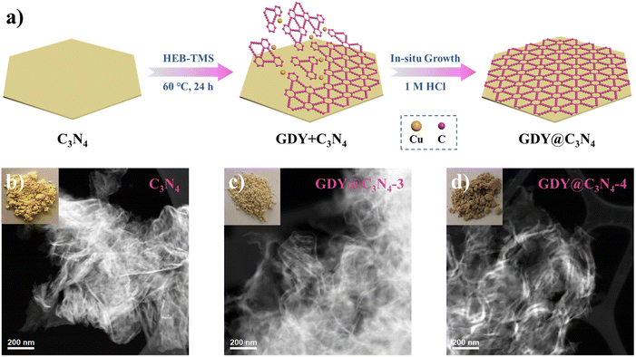 | ||
| Fig. 1 (a) Schematic illustration for the preparation of GDY@C3N4via a one-pot method. Photographs of samples and corresponding HAADF-STEM images of (b) C3N4, (c) GDY@C3N4-3, (d) GDY@C3N4-4. | ||
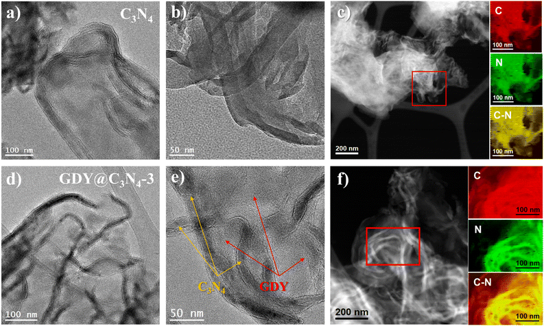
To further reveal the microstructure of C3N4 and GDY@C3N4, transmission electron microscopy (TEM) measurements were carried out. As displayed in Fig. 2a, b and S3,† C3N4 showed curled edges and an abundance of pores with size of several tens of nanometers. The formation of these pores may originate from gas emissions during the thermal polymerization of urea, which contributes to the diffusion of the reactants.31 The elemental composition mapping of C3N4 was determined by electron energy loss spectroscopy (EELS) from the red square region in the HAADF-STEM micrograph (Fig. 2c). It can be seen that the C3N4 nanosheets showed a uniform distribution of C and N elements throughout the structure, although C3N4 and GDY were not easily distinguished in TEM images due to the similar atomic numbers of C and N as well as the amorphous property. Compared with the pristine C3N4, two different components can be clearly observed from the TEM image of GDY@C3N4, including the curled filamentary C3N4 and the flattened thinner flakes of GDY (Fig. 2d, e and S4†). In contrast to previous reports,21–23 GDY was evenly adhered around the C3N4 rather than forming only regional interfaces, suggesting an omnidirectional growth of GDY on the surface of C3N4. This view was further confirmed by the EELS mapping of the GDY@C3N4. Fig. 2f shows a homogeneous elemental distribution of C and N, where there was an obvious expansion of the C distribution on GDY@C3N4, which indicated the successful coating of C3N4 by GDY. The unique encapsulation structure of GDY@C3N4 photocatalysts predicts excellent charge separation/transfer ability and promising photocatalytic performance can be expected.32
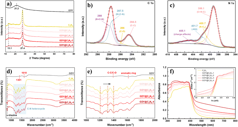
X-ray diffraction (XRD) was used to investigate the crystal structures of the synthesized samples (Fig. 3a). GDY exhibited a typical broad and weak diffraction peak centred at around 21.2°, corresponding to the characteristic (002) plane of the graphite-type carbon, which reveals a distortion of the ordered arrangement of GDY along its stacking direction.17,33 Two obvious diffraction peaks at 13.1° and 27.4° can be observed from the XRD diagram of C3N4, which are assigned to the (100) plane from the interplanar stacking of the conjugate segments and the (002) plane originating from interlayer structural packing units, respectively.7,34,35 The characteristic peaks of C3N4 were retained in the GDY@C3N4 samples, suggesting that the presence of GDY did not disrupt the crystal structure of C3N4. Diffraction peaks belonging to GDY cannot be detected in GDY@C3N4 composites due to the poor crystallinity and low content.26 However, it is worth mentioning that the characteristic peaks corresponding to C3N4 decreased with increased amount of GDY, which could be attributed to the partial shielding effect of the GDY, further validating the homogeneous growth of the GDY. The chemical composition of GDY@C3N4 was analyzed by X-ray photoelectron spectra (XPS). The XPS general survey indicated the presence of C, N and O (Fig. S5†). No peaks attributed to Cu were observed, which suggested the complete removal of Cu after acid treatment (Fig. S6†). The high-resolution C 1s XPS spectra of GDY@C3N4 display four sub-peaks (Fig. 3b), where the peaks located at 284.5 and 286.0 eV can be assigned to C![[double bond, length as m-dash]](https://www.rsc.org/images/entities/char_e001.gif) C (sp2) and C–O, while the peaks at 287.5 and 288 eV can be attributed to C–N (sp2) in C3N4, respectively.21,36–39 The N 1s XPS spectra of GDY@C3N4 can also be deconvoluted into four sub-peaks at 399.1 eV for sp2-hybridized N in the C–N heterocycle (C
C (sp2) and C–O, while the peaks at 287.5 and 288 eV can be attributed to C–N (sp2) in C3N4, respectively.21,36–39 The N 1s XPS spectra of GDY@C3N4 can also be deconvoluted into four sub-peaks at 399.1 eV for sp2-hybridized N in the C–N heterocycle (C![[double bond, length as m-dash]](https://www.rsc.org/images/entities/char_e001.gif) N–C), 400.7 eV for sp3-hybridized N (N–C3), 401.7 eV for amino groups (–NH) and 405.1 eV for charge effects, respectively (Fig. 3c).40–42 Fourier-transform infrared (FT-IR) spectroscopy was conducted to further examine the functional groups of as-prepared samples (Fig. 3d and e). The peaks located at 1381 and 1610 cm−1 in GDY were assigned to the stretching vibrations of C–C/C–O bonds and the skeletal vibrations of the aromatic ring, respectively.30 A series of peaks can be observed in the range of 1200–1700 cm−1 in pristine C3N4 ascribed to the typical stretching vibrations of C–N heterocycles, while the peak located at 805 cm−1 can be attributed to the characteristic breathing mode of s-triazine units.43 In addition, several broad peaks in the range 3000–3400 cm−1 are designated as the stretching vibrations for amino groups.44 No significant changes were observed in the FT-IR spectra of GDY@C3N4, indicating that the in situ growth of GDY has no effect on the structure of C3N4. Similarly, no distinct peaks belonging to GDY can be observed in the GDY@C3N4 samples due to the peak overlap between the C–N heterocycle and aromatic ring as well as the low content of GDY, which is consistent with the XRD results. Of note, the peaks belonging to C–N heterocycles shifted to higher wavenumbers in GDY@C3N4 compared to the pure C3N4, indicating a strong interaction between GDY and C3N4 (Fig. 3e). This result demonstrates the formation of chemical bonds and heterojunctions between C3N4 and GDY, which serves as charge transfer channels to enhance the photocatalytic performance.21,37,45
N–C), 400.7 eV for sp3-hybridized N (N–C3), 401.7 eV for amino groups (–NH) and 405.1 eV for charge effects, respectively (Fig. 3c).40–42 Fourier-transform infrared (FT-IR) spectroscopy was conducted to further examine the functional groups of as-prepared samples (Fig. 3d and e). The peaks located at 1381 and 1610 cm−1 in GDY were assigned to the stretching vibrations of C–C/C–O bonds and the skeletal vibrations of the aromatic ring, respectively.30 A series of peaks can be observed in the range of 1200–1700 cm−1 in pristine C3N4 ascribed to the typical stretching vibrations of C–N heterocycles, while the peak located at 805 cm−1 can be attributed to the characteristic breathing mode of s-triazine units.43 In addition, several broad peaks in the range 3000–3400 cm−1 are designated as the stretching vibrations for amino groups.44 No significant changes were observed in the FT-IR spectra of GDY@C3N4, indicating that the in situ growth of GDY has no effect on the structure of C3N4. Similarly, no distinct peaks belonging to GDY can be observed in the GDY@C3N4 samples due to the peak overlap between the C–N heterocycle and aromatic ring as well as the low content of GDY, which is consistent with the XRD results. Of note, the peaks belonging to C–N heterocycles shifted to higher wavenumbers in GDY@C3N4 compared to the pure C3N4, indicating a strong interaction between GDY and C3N4 (Fig. 3e). This result demonstrates the formation of chemical bonds and heterojunctions between C3N4 and GDY, which serves as charge transfer channels to enhance the photocatalytic performance.21,37,45
To evaluate the light absorption capacity of the as-prepared samples, UV-vis diffuse reflectance spectroscopy (DRS) was carried out. Compared to pure C3N4, the introduction of GDY significantly improves the absorption in the visible region owing to its excellent visible light absorption, and the intensity simultaneously enhances with the increased amount of GDY.25 The optical bandgaps were estimated through the Kubelka–Munk (K–M) method, where the bandgap of C3N4 was determined to be 2.7 eV, while the bandgap for GDY@C3N4 samples reduced to 2.6 eV. The strong visible light absorption and narrow bandgap make GDY@C3N4 a promising visible-light driven photocatalyst.
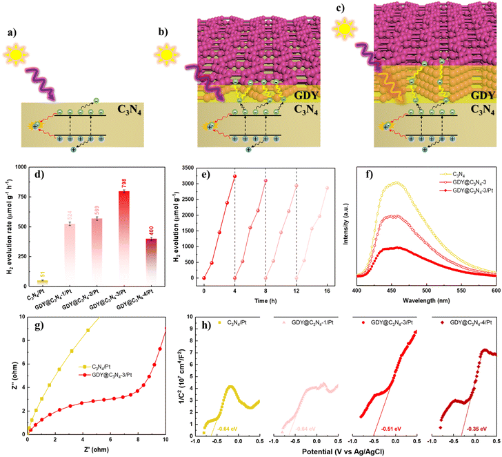
The photocatalytic activities of C3N4 and GDY@C3N4 were estimated towards the hydrogen evolution reaction (HER) under visible light illumination (>420 nm), employing 1 wt% of Pt as a cocatalyst. Triethanolamine was used as the sacrificial reagent to deplete the photogenerated holes. The photocatalytic H2 production rate of C3N4, which showed negligible H2 generation, was significantly improved when covered by GDY. The photocatalytic activity increased with the content of GDY and reached an optimal photoactivity of 798 μmol g−1 h−1 for GDY@C3N4-3/Pt (Fig. 4d and S7†), exceeding that of C3N4/Pt by approximately 15.6-fold. A further increase in GDY reduced the H2 evolution rate, probably because an excessively thick GDY layer disrupts the delicate balance between photogenerated carrier separation and light utilization efficiency (Fig. 4a–c).21 In addition, no significant deactivation was observed after four consecutive cycles, implying the robust stability of GDY@C3N4-3/Pt (Fig. 4e). Such enhancement in photocatalytic performance and high stability is attributed to the excellent conductivity and protection of the GDY layer, which can effectively facilitate the transfer of photogenerated carriers and also can inhibit the photocorrosion.46,47
To further validate the role of the GDY layer in the GDY@C3N4 heterojunction, photoluminescence (PL) spectroscopy and photoelectrochemical measurements were carried out. As exhibited in Fig. 4f, GDY@C3N4-3 showed an obvious PL quenching compared with pure C3N4, which suggested that GDY could efficiently extract the photogenerated carriers from C3N4.48 The introduction of Pt nanoparticles further facilitated charge carrier separation. Electrochemical impedance spectroscopy (EIS) was performed to reveal the charge carrier transfer capability.49 The smaller radius of curvature for GDY@C3N4-3/Pt indicated a lower charge transfer resistance than C3N4/Pt (Fig. 4g). Mott–Schottky (MS) measurements were employed to evaluate the band structure of the photocatalysts.50,51 All the MS plots showed positive slopes, indicating that both C3N4/Pt and GDY@C3N4/Pt are n-type semiconductors (Fig. 4h). Compared to C3N4/Pt, there was a positive shift of −0.29 V in the flat-band potential of GDY@C3N4/Pt samples, and more positive shift was observed with increased GDY content. This positive shift can be attributed to the construction of an internal electric field at the GDY–C3N4 interface, which is beneficial for the separation of photogenerated carriers, consistent with previous results.52
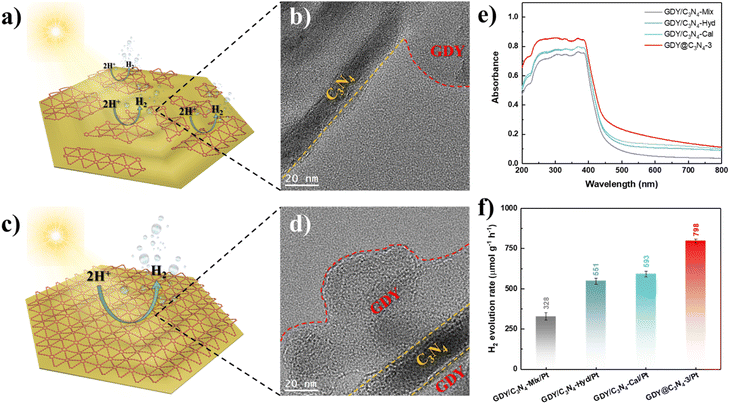
Based on the above-mentioned results, the in situ growth of GDY on the surface of C3N4 is an effective method for enhancing its photocatalytic activity. To further demonstrate the superiority of this strategy, three samples were synthesized using physical mixing, hydrothermal treatment and calcination treatment according to previous studies, namely GDY/C3N4-Mix, GDY/C3N4-Hyd and GDY/C3N4-Cal, respectively.21,22 C3N4 still maintained the same filamentous morphology after treatments due to its thermal stability (Fig. S8†). Although these methods can achieve the hybridization of GDY with C3N4 through the π–π stacking interaction, the formed GDY/C3N4 heterojunction exhibited locality, which may be filled in the voids of C3N4 or partially attached to its surface (Fig. 5a, b and S9†). The EELS mappings of GDY/C3N4-Hyd and GDY/C3N4-Cal showed a homogeneous elemental distribution of C and N, indicating that most of the GDY was present in the voids of C3N4 and cannot be distinguished (Fig. S10†). These results are strikingly different from those observed in GDY@C3N4 samples, which achieved a complete coating of GDY on C3N4 (Fig. 5c, d and 2f). The GDY/C3N4 samples with localized heterojunctions displayed lower light absorption capability and H2 generation efficiency compared with the uniformly coated GDY@C3N4 sample (Fig. 5e, f and S11). Therefore, the in situ growth of GDY enabled an integral GDY@C3N4 heterojunction instead of localized heterojunctions, which maximizes the advantages of GDY to promote the photogenerated carrier separation and transfer efficiently.
4 Conclusions
In summary, we have developed a deprotection-free strategy directly using HEB-TMS as a precursor to in situ grow GDY on C3N4. This one-pot method realized the uniform coating of GDY, which efficiently promotes the photogenerated carrier separation/transfer and greatly improves the photocatalytic activity in the visible region. The optimized GDY@C3N4 achieved 15.6-fold hydrogen production efficiency compared to pure C3N4. Moreover, the as-prepared GDY@C3N4 exhibited much better photocatalytic activity than the GDY/C3N4 samples constructed by physical mixing, hydrothermal treatment and calcination treatment, further demonstrating the excellence of this approach. This work provides a facile and universal strategy for the design of GDY-based heterojunctions for photocatalytic hydrogen generation.Conflicts of interest
There are no conflicts to declare.Acknowledgements
ICN2 acknowledges funding from Generalitat de Catalunya 2017 SGR 327. ICN2 is supported by the Severo Ochoa program from Spanish MINECO (Grant No. SEV-2017-0706). C. W and M. N. G. acknowledge the public grant overseen by the French National Research Agency (ANR) as part of the ERANET-ACT3 call program and the Paris Ile-de-France Region (DIM RESPORE-2021-27) for financial support. MNG thanks the French National Research Agency (ANR), through the Ingen Cat project (ANR-20-CE43-0014), for the financial support.References
- H. Nishiyama, T. Yamada, M. Nakabayashi, Y. Maehara, M. Yamaguchi, Y. Kuromiya, Y. Nagatsuma, H. Tokudome, S. Akiyama, T. Watanabe, R. Narushima, S. Okunaka, N. Shibata, T. Takata, T. Hisatomi and K. Domen, Nature, 2021, 598, 304–307 CrossRef CAS PubMed
.
- T. Takata, J. Jiang, Y. Sakata, M. Nakabayashi, N. Shibata, V. Nandal, K. Seki, T. Hisatomi and K. Domen, Nature, 2020, 581, 411–414 CrossRef CAS PubMed
.
- C. Wang, B. Weng, Y. Liao, B. Liu, M. Keshavarz, Y. Ding, H. Huang, D. Verhaeghe, J. A. Steele, W. Feng, B. L. Su, J. Hofkens and M. B. J. Roeffaers, Chem. Commun., 2022, 58, 10691–10694 RSC
.
- C. Wang, J. Li, E. Paineau, A. Laachachi, C. Colbeau-Justin, H. Remita and M. N. Ghazzal, J. Mater. Chem. A, 2020, 8, 10779–10786 RSC
.
- X. Yuan, C. Wang, D. Dragoe, P. Beaunier, C. Colbeau-Justin and H. Remita, Appl. Catal., B, 2021, 281, 119457 CrossRef CAS
.
- M. Z. Rahman, M. G. Kibria and C. B. Mullins, Chem. Soc. Rev., 2020, 49, 1887–1931 RSC
.
- X. Wang, K. Maeda, A. Thomas, K. Takanabe, G. Xin, J. M. Carlsson, K. Domen and M. Antonietti, Nat. Mater., 2009, 8, 76–80 CrossRef CAS PubMed
.
- J. Li, X. Gao, L. Zhu, M. N. Ghazzal, J. Zhang, C.-H. Tung and L.-Z. Wu, Energy Environ. Sci., 2020, 13, 1326–1346 RSC
.
- Y. Fang, Y. Liu, L. Qi, Y. Xue and Y. Li, Chem. Soc. Rev., 2022, 51, 2681–2709 RSC
.
- X. Gao, J. Li, R. Du, J. Zhou, M.-Y. Huang, R. Liu, J. Li, Z. Xie, L.-Z. Wu, Z. Liu and J. Zhang, Adv. Mater., 2017, 29, 1605308 CrossRef PubMed
.
- Y. Jiao, A. Du, M. Hankel, Z. Zhu, V. Rudolph and S. C. Smith, Chem. Commun., 2011, 47, 11843–11845 RSC
.
- C. Huang, Y. Li, N. Wang, Y. Xue, Z. Zuo, H. Liu and Y. Li, Chem. Rev., 2018, 118, 7744–7803 CrossRef CAS PubMed
.
- S. Liang, H. Deng, Z. Zhou and W. Y. Wong, EcoMat, 2022, e12297, DOI:10.1002/eom2.12297
.
- F. Xu, K. Meng, B. Zhu, H. Liu, J. Xu and J. Yu, Adv. Funct. Mater., 2019, 29, 1904256 CrossRef CAS
.
- J. Li, X. Gao, B. Liu, Q. Feng, X. B. Li, M. Y. Huang, Z. Liu, J. Zhang, C. H. Tung and L. Z. Wu, J. Am. Chem. Soc., 2016, 138, 3954–3957 CrossRef CAS PubMed
.
- J. Li, A. Slassi, X. Han, D. Cornil, M. H. Ha-Thi, T. Pino, D. P. Debecker, C. Colbeau-Justin, J. Arbiol, J. Cornil and M. N. Ghazzal, Adv. Funct. Mater., 2021, 31, 2100994 CrossRef CAS
.
- J. Li, X. Han, D. Wang, L. Zhu, M. H. Ha-Thi, T. Pino, J. Arbiol, L. Z. Wu and M. Nawfal Ghazzal, Angew. Chem., Int. Ed., 2022, 61, e202210242 CAS
.
- J. Li, Z. Xie, Y. Xiong, Z. Li, Q. Huang, S. Zhang, J. Zhou, R. Liu, X. Gao, C. Chen, L. Tong, J. Zhang and Z. Liu, Adv. Mater., 2017, 29, 1700421 CrossRef PubMed
.
- R. Wang, M. Shi, F. Xu, Y. Qiu, P. Zhang, K. Shen, Q. Zhao, J. Yu and Y. Zhang, Nat. Commun., 2020, 11, 4465 CrossRef CAS PubMed
.
- L. Zhang, Y. Wu, J. Li, Z. Jin, Y. Li and N. Tsubaki, Mater. Today Phys., 2022, 27, 100767 CrossRef CAS
.
- Q. Xu, B. Zhu, B. Cheng, J. Yu, M. Zhou and W. Ho, Appl. Catal., B, 2019, 255, 117770 CrossRef CAS
.
- H. Si, Q. Deng, C. Yin, J. Zhou, S. Zhang, Y. Zhang, Z. Liu, J. Zhang, J. Zhang and J. Kong, J. Alloys Compd., 2020, 833, 155054 CrossRef CAS
.
- K. Yang, T. Liu, D. Xiang, Y. Li and Z. Jin, Sep. Purif. Technol., 2022, 298, 121564 CrossRef CAS
.
- Y. Wang, Y. Zhang, Y. Wang, C. Zeng, M. Sun, D. Yang, K. Cao, H. Pan, Y. Wu, H. Liu and R. Yang, ACS Appl. Mater. Interfaces, 2021, 13, 40629–40637 CrossRef CAS PubMed
.
- H.-Y. Si, C.-J. Mao, J.-Y. Zhou, X.-F. Rong, Q.-X. Deng, S.-L. Chen, J.-J. Zhao, X.-G. Sun, Y. M. Shen, W.-J. Feng, P. Gao and J. Zhang, Carbon, 2018, 132, 598–605 CrossRef CAS
.
- C. Sun, Y. Liu, Z. Wang, P. Wang, Z. Zheng, H. Cheng, X. Qin, X. Zhang, Y. Dai and B. Huang, J. Alloys Compd., 2021, 868, 159045 CrossRef CAS
.
- Y. Li, H. Yang, G. Wang, B. Ma and Z. Jin, ChemCatChem, 2020, 12, 1985–1995 CrossRef CAS
.
- J. Li, M. Li, H. Li and Z. Jin, J. Mater. Chem. C, 2022, 10, 2181–2193 RSC
.
- T. Yan, H. Liu and Z. Jin, ACS Appl. Mater. Interfaces, 2021, 13, 24896–24906 CrossRef CAS PubMed
.
- G. Li, Y. Li, H. Liu, Y. Guo, Y. Li and D. Zhu, Chem. Commun., 2010, 46, 3256–3258 RSC
.
- Y. Hou, Z. Wen, S. Cui, X. Guo and J. Chen, Adv. Mater., 2013, 25, 6291–6297 CrossRef CAS PubMed
.
- X. Zhou, B. Fu, L. Li, Z. Tian, X. Xu, Z. Wu, J. Yang and Z. Zhang, Nat. Commun., 2022, 13, 5770 CrossRef CAS PubMed
.
- J. He, N. Wang, Z. Cui, H. Du, L. Fu, C. Huang, Z. Yang, X. Shen, Y. Yi, Z. Tu and Y. Li, Nat. Commun., 2017, 8, 1172 CrossRef PubMed
.
- P. Niu, L. Zhang, G. Liu and H.-M. Cheng, Adv. Funct. Mater., 2012, 22, 4763–4770 CrossRef CAS
.
- X.-L. Pu, X.-C. Yang, S.-S. Liang, W. Wang, J.-T. Zhao and Z.-J. Zhang, J. Mater. Chem. A, 2021, 9, 22373–22379 RSC
.
- R. Matsuoka, R. Sakamoto, K. Hoshiko, S. Sasaki, H. Masunaga, K. Nagashio and H. Nishihara, J. Am. Chem. Soc., 2017, 139, 3145–3152 CrossRef CAS PubMed
.
- Y.-Y. Han, X.-L. Lu, S.-F. Tang, X.-P. Yin, Z.-W. Wei and T.-B. Lu, Adv. Energy Mater., 2018, 8, 1702992 CrossRef
.
- J. Li, X. Gao, Z. Li, J. H. Wang, L. Zhu, C. Yin, Y. Wang, X. B. Li, Z. Liu, J. Zhang, C. H. Tung and L. Z. Wu, Adv. Funct. Mater., 2019, 29, 1808079 CrossRef
.
- J. Li, X. Gao, X. Jiang, X.-B. Li, Z. Liu, J. Zhang, C.-H. Tung and L.-Z. Wu, ACS Catal., 2017, 7, 5209–5213 CrossRef CAS
.
- P. Kuang, B. Zhu, Y. Li, H. Liu, J. Yu and K. Fan, Nanoscale Horiz., 2018, 3, 317–326 RSC
.
- D. J. Martin, K. Qiu, S. A. Shevlin, A. D. Handoko, X. Chen, Z. Guo and J. Tang, Angew. Chem., Int. Ed., 2014, 53, 9240–9245 CrossRef CAS PubMed
.
- L. Zhang, R. Long, Y. Zhang, D. Duan, Y. Xiong, Y. Zhang and Y. Bi, Angew. Chem., Int. Ed., 2020, 59, 6224–6229 CrossRef CAS PubMed
.
- Q. Xu, C. Jiang, B. Cheng and J. Yu, Dalton Trans., 2017, 46, 10611–10619 RSC
.
- B. Wang, J. Zhang and F. Huang, Appl. Surf. Sci., 2017, 391, 449–456 CrossRef CAS
.
- N. Yang, Y. Liu, H. Wen, Z. Tang, H. Zhao, Y. Li and D. Wang, ACS Nano, 2013, 7, 1504–1512 CrossRef CAS PubMed
.
- B. Weng, M.-Y. Qi, C. Han, Z.-R. Tang and Y.-J. Xu, ACS Catal., 2019, 9, 4642–4687 CrossRef CAS
.
- Y. Shang, X. Chen, W. Liu, P. Tan, H. Chen, L. Wu, C. Ma, X. Xiong and J. Pan, Appl. Catal., B, 2017, 204, 78–88 CrossRef CAS
.
- Y. Guo, J. Li, Y. Yuan, L. Li, M. Zhang, C. Zhou and Z. Lin, Angew. Chem., Int. Ed. Engl., 2016, 55, 14693–14697 CrossRef CAS PubMed
.
- B. Weng and Y. J. Xu, ACS Appl. Mater. Interfaces, 2015, 7, 27948–27958 CrossRef CAS PubMed
.
- J. Li, X. Yang, C. Ma, Y. Lei, Z. Cheng and Z. Rui, Appl. Catal., B, 2021, 291, 120053 CrossRef CAS
.
- X. Yuan, D. Dragoe, P. Beaunier, D. B. Uribe, L. Ramos, M. G. Méndez-Medrano and H. Remita, J. Mater. Chem. A, 2020, 8, 268–277 RSC
.
- I. A. Digdaya, G. W. P. Adhyaksa, B. J. Trzesniewski, E. C. Garnett and W. A. Smith, Nat. Commun., 2017, 8, 15968 CrossRef CAS PubMed
.
Footnotes |
| † Electronic supplementary information (ESI) available. See DOI: https://doi.org/10.1039/d2ta09918g |
| ‡ These authors contributed equally to this work. |
| This journal is © The Royal Society of Chemistry 2023 |

