 Open Access Article
Creative Commons Attribution 3.0 Unported Licence
Atomically precise metal nanoclusters as catalysts for electrocatalytic CO2 reduction
Tokuhisa
Kawawaki
 *ab,
Tomoshige
Okada
a,
Daisuke
Hirayama
a and
Yuichi
Negishi
 *ab
*ab
aDepartment of Applied Chemistry, Faculty of Science, Tokyo University of Science, 1-3 Kagurazaka, Shinjuku-ku, Tokyo 162-8601, Japan. E-mail: kawawaki@rs.tus.ac.jp; negishi@rs.tus.ac.jp
bResearch Institute for Science & Technology, Tokyo University of Science, 2641 Yamazaki, Noda, Chiba 278-8510, Japan
First published on 12th October 2023
Abstract
Electrochemical carbon dioxide (CO2) reduction can be used to convert CO2 into various compounds at room temperature and ambient pressure using electricity generated from renewable energy sources. This technology is indispensable in establishing an environmentally responsible and sustainable society. However, further improvements in the activity and selectivity require the development of electrocatalysts that can directly serve as the actual reaction sites. In recent years, metal nanoclusters, which are metal particles with a size of approximately 1 nm, have been reported to be capable of electrochemical CO2 reduction with high activity and selectivity, owing to their unique geometric/electronic structure. This review summarizes the synthesis methods of atomically precise metal nanoclusters and their application in electrochemical CO2 reduction. We expect that this review will help clarify the current status of these studies and further accelerate the research on highly active and selective CO2 reduction catalysts using metal nanoclusters.
1. Introduction
1.1 Atomically precise metal nanoclusters as catalysts
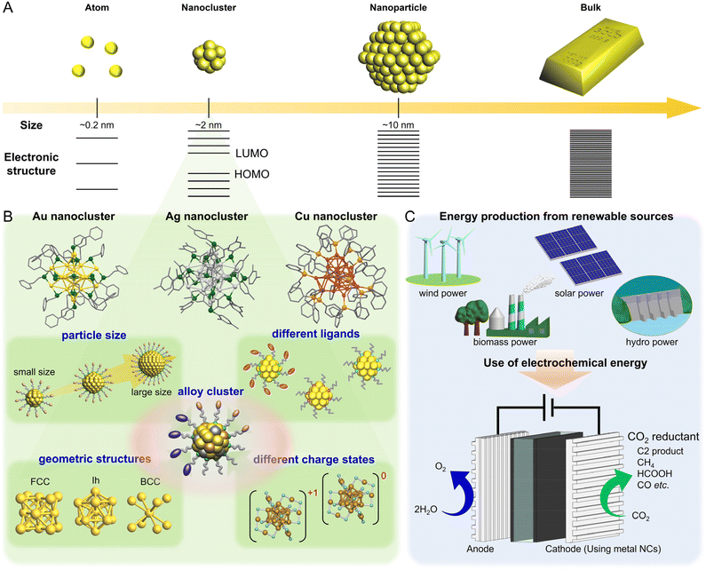
Among nano-sized materials, an aggregate of metal atoms with a size of approximately 1 nm is called a metal nanocluster (NC).1–28 Metal NCs have different physical/chemical properties than bulk metals and relatively larger (>5 nm) metal nanoparticles (NPs), which are attributed to quantum size effects (Fig. 1A).29–31 Furthermore, the properties and functions of NCs show a remarkable dependence on the number of constituent atoms, unlike metal NPs.32–36 Therefore, if the number of constituent atoms can be precisely controlled in the metal NCs, it is possible to create a wide variety of properties and functions with the difference of a single atom. It has become possible not only to control the size of metal NCs but also to control heterometal doping37,38 and geometric structures39–42 at the atomic level. Thus, metal NCs are expected to be applied as key components in next-generation materials. In particular, for metal NCs protected by ligands, unlike gas-phase generated clusters, their geometric structures have been revealed by single-crystal X-ray diffraction (SC-XRD), and the combination of density functional theory (DFT) calculations and SC-XRD can reveal the electronic structure of metal NCs and their origin. Because of these characteristics, metal NCs have attracted significant attention in the development of materials based on luminescence control43–47 and chiral control,48,49 environmental fields,50–54 energy harvesting,51,55–59 and biological sensor45,60,61 and catalytic reactions.62–64 Metal NCs are highly active catalysts because of their unique geometric/electronic structure and small size. Moreover, theoretical calculations of the adsorption/desorption energies of reacting molecules based on the geometric structure obtained by SC-XRD can help elucidate the mechanisms of various reactions.The studies on metal NCs began after the 1950s, with efforts to synthesize metal NCs consisting of group 8–10 elements and ligands such as phosphine, halogen (X), and carbon monoxide (CO).65 In 1994, Brust and Schiffrin et al. reported the synthesis of thiolate (SR)-protected gold (Au) NCs (Aun(SR)m).66 Because these NCs have extremely high thermal and chemical stability owing to the strong bonding between Au and sulfur (S), and can be synthesized by simply mixing reagents under atmospheric conditions, research on Aun(SR)m increased dramatically after 2000. At that time, Aun(SR)m could only be treated as a mixture with a distribution in the number of constituent atoms; however, with the establishment of highly resolved separation techniques by Whetten et al. and Murray et al., the chemical composition of Aun(SR)m could be highly controlled.67–69 In 2005, Tsukuda and Negishi were the first to systematically separate Aun(SR)m with a well-defined chemical composition.70–72 In 2007, Kornberg et al. determined the geometric structure of Au102(p-MBA)44 (p-MBA: 4-mercaptobenzoic acid) by SC-XRD,73 and since then, the chemical compositions and geometric structures have been determined for several Aun(SR)m. In addition, SR-protected silver (Ag) and copper (Cu) NCs have been synthesized in numerous studies, and the research has been extended to metal NCs capped by other ligands (Fig. 1B).
1.2 Electrochemical carbon dioxide reduction
Recently, interest in carbon dioxide (CO2) reduction using electrocatalysts has been growing. In 1967, Manabe presented a “coupled atmosphere-ocean model” showing that CO2 has a significant impact on long-term climate change, which bolstered global efforts to reduce CO2 emissions.74 In 2015, the Paris Agreement was adopted to solve the global warming problem, and “achieving carbon neutrality” is now a long-term goal shared among numerous countries.75 Herein, carbon neutral means the reduction of the total greenhouse gases, including CO2, to net zero. To achieve this, various efforts are being actively pursued worldwide. In particular, the transformation of CO2 into useful organic compounds by reduction has been demonstrated as a promising method for directly decreasing CO2 emissions.75–77The most notable CO2 reduction reaction (CRR) is the Sabatier reaction (methanation), in which hydrogen (H2) and CO2 are converted to methane (CH4) and water under high temperature and high pressure using a metal catalyst. This method has been used for industrially synthesizing methane since its discovery by Sabatier and Senderens in 1902.78,79 Additionally, the reverse water gas shift reaction that produces CO and water (H2O) from CO2 and H2 is often used in industry. However, the current system produces H2 from fossil fuels, such as natural gas reforming or coal gasification, which emit a large amount of CO2 during the production process. Alternatively, if CO2 can be directly reduced by electrochemical reduction using water as an electron and proton source and electricity derived from renewable energy sources, then CO2 can be directly converted into other organic compounds without using H2 derived from fossil fuels (Fig. 1C). Electrochemical CRR is becoming easier to industrialize because it is possible to divert the water-electrolysis hydrogen-production technology currently under development.75,80
Research on electrochemical CRRs began in the 1950s.81 In 1985, Hori et al. quantitatively analyzed the amount of liquid- and gas-phase products produced by electrolytic reduction, which corresponded to the amount of applied electricity (i.e., performed with a Faraday efficiency (FE) of 100%).82 Furthermore, their study revealed that the products differed depending on the metal electrodes:83–86 (1) nickel (Ni), iron (Fe), platinum (Pt), and titanium (Ti) produce H2; (2) lead (Pb), mercury (Hg), thallium (Tl), indium (In), tin (Sn), cadmium (Cd), and bismuth (Bi) primarily produce formic acid (HCOOH); (3) Au, Ag, zinc (Zn), palladium (Pd), and gallium (Ga) mainly produce CO; and (4) Cu produces various hydrocarbons, aldehydes, and alcohols. For these metal catalysts, increases in specific surface area, crystal facet control, alloying, and support interactions for CRR catalysts have been investigated, along with advances in nanotechnology, since the 2000s.87–89 Thereby, overvoltage suppression and improvements in product selectivity and durability have been achieved. However, further improvements in the activity, selectivity, and durability are required, and research in this area remains active. In this review, we discuss the use of atomically precise metal NCs for electrochemical CRRs. Therefore, readers interested in studying electrochemical CRRs using nanomaterials other than metal NCs (metal NPs,89–92 single atoms,93–97 and molecular catalysts98–100) are invited to read the review articles that describe them in detail. Gas-phase generated clusters are excluded from this review because there are few reports on CO2 reduction.
1.3 Purpose and contents of this review
Metal NCs have significant potential not only for use as various thermal catalysts51,52,54,101 and photocatalysts102–114 but also as electrocatalysts,101,115–117 particularly in hydrogen evolution reactions (HER),118–123 oxygen evolution reactions (OER),120,124–126 oxygen reduction reactions (ORR),58,120,127–134 and alcohol and HCOOH oxidation reactions.135–137 In addition, the application of metal NCs as electrochemical CRR catalysts1,55,57,113–115,138–150 has been widely studied. However, CRR activity is often evaluated on accidentally synthesized metal NCs, and there are not many examples of metal NCs synthesized based on standard design principles. The reason for this is the lack of deep understanding regarding the synthetic methods and geometric/electronic structures of metal NCs and their resulting correlation with CRR activity. In this review, we summarize the synthesis methods and geometric/electronic structures of metal NCs, and the representative studies on electrochemical CRRs using these materials. Furthermore, on the basis of this knowledge, we discuss (1) the synthesis and geometric/electronic structure of metal NCs as high-performance CRR catalysts, (2) the appropriate experimental conditions (e.g., support and metal NCs) for the application of high-performance CRR catalysts, and (3) the CRR mechanism of the metal NC catalysts. Through these discussions, we hope to promote the establishment of clear guidelines for the design of metal NCs that are suitable for electrochemical CRRs, thereby enhancing the development of metal NCs and electrochemical CRR catalysis.In section 2, we first describe the synthesis methods and geometric/electronic structures of the predominant metal NCs that have been applied to CO2 reduction in previous studies, categorized by the metal species. Then, in section 3, we discuss the catalytic activities of metal NCs in electrochemical CRRs and their mechanisms. In section 4, we summarize the conclusions of this review, and in section 5, we briefly describe the outlook for the future.
2. Synthesis of atomically precise metal nanoclusters
Metal NCs have high surface energy owing to their small size and can easily aggregate or degrade in air if not specially handled. Thus, metal NCs are often protected using organic ligands, which facilitates handling and modification. Furthermore, by controlling the ligands, metal species, and reaction rates, metal NCs with various numbers of constituent atoms, chemical compositions, and structures can be synthesized. In this section, we describe the synthesis of mainly Au, Ag, and Cu NCs, among those applied to electrochemical CRRs, which have relatively high stability and can be synthesized with atomic precision, as well as the effects of ligands and alloying. Multiple reviews have focused on the synthesis of metal NCs, and thus readers who would like to know more details should refer to those articles.32–362.1 Synthesis of gold nanocluster
Aun(SR)m have relatively high stability and more examples have been reported at an early stage, compared with SR-protected Ag and Cu NCs.68,71,151,152 Aun(SR)m also possess useful physicochemical properties such as photoexcited luminescence, thermocatalysis, electrocatalysis, and magnetism, and many studies have reported on their application in electrochemical CRRs. In this section, we describe the synthesis of Au NCs, particularly those protected by SR, phosphine, alkynyl (C![[triple bond, length as m-dash]](https://www.rsc.org/images/entities/char_e002.gif) CR), and N-heterocyclic carbene (NHC).
CR), and N-heterocyclic carbene (NHC).
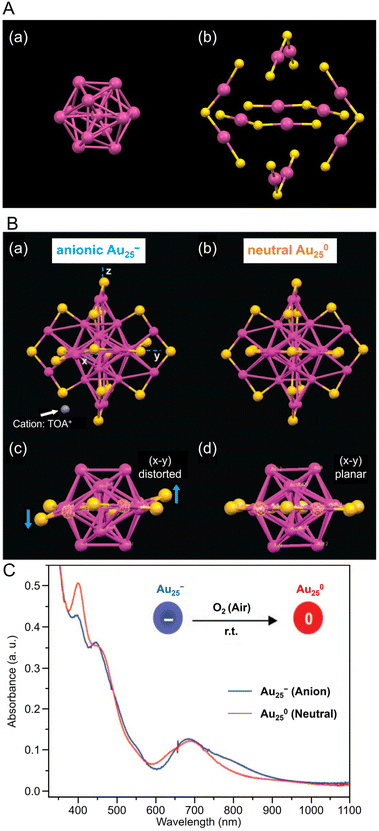 | ||
| Fig. 2 (A) (a) Au13 core and (b) Au–S staple structure of [Au25(PET)18]−. (B) Comparison of the crystal structures of (a, c) [Au25(PET)18]− and (b, d) [Au25(PET)18]0. Both Au25(PET)18 in (A) and (B) are capped by 18 PET ligands (for clarity C and H atoms are omitted); for [Au25(PET)18]−, the counterion is tetraoctylammonium (TOA+; only N (in blue) is shown for clarity). (C) The optical absorption spectra of [Au25(PET)18]− (blue profile) and [Au25(PET)18]0 (red profile) in solution. (B) and (C) are reproduced with permission from ref. 156. Copyright 2008 American Chemical Society. | ||
Owing to its relatively stable electronic/geometric structure, Au25(SR)18 can be synthesized with a variety of SR ligands (including hydrophilic SR ligands). For example, in 2016, Li and Jin et al. synthesized 1-naphthalenethiolate (SNap)-protected Au25(SNap)18 using a two-step method. First, they synthesized hexanethiolate (SC6H13)-protected Au25(SC6H13)18, then dissolved it in toluene and reacted with naphthalene thiol to synthesize Au25(SNap)18.162 For the structure of Au25(SNap)18, the SC-XRD results revealed that Au2(SNap)3 is coordinated as a staple around an icosahedral Au13 core.
Many studies have attempted to alloy Au25(SR)18 because of its high stability.163 As a result, many metals, such as Ag,164–167 Cu,168–173 Pt,174–177 Pd,175,178–181 Hg,182,183 Cd,183–185 and Ir,186 can be doped into Au25(SR)18. In 2015, Jiang and Lee et al. reported the synthesis of MAu24(SC6H13)18 (M = Pd or Pt) using HAuCl4·3H2O and hydrogen hexachloroplatinate(IV) (H2PtCl6·6H2O) or Na2PdCl4·6H2O as precursors, and their electronic structures were elucidated (Fig. 3Aa).187 [MAu24(SC6H13)18]0 has a 6-electron superatomic configuration (1S21P4), whereas [MAu24(SC6H13)18]2− has an 8-electron superatomic configuration (1S21P6), which is similar to the trend observed in [Au25(PET)18]z (z = −1, 0, +1). Furthermore, the Jahn–Teller-like distortion of [MAu24(SC6H13)18]0 results in 1P orbital splitting, which causes strong absorption in the near-infrared region (Fig. 3Ab). These results agree well with the predicted optical absorption spectra from simulations.
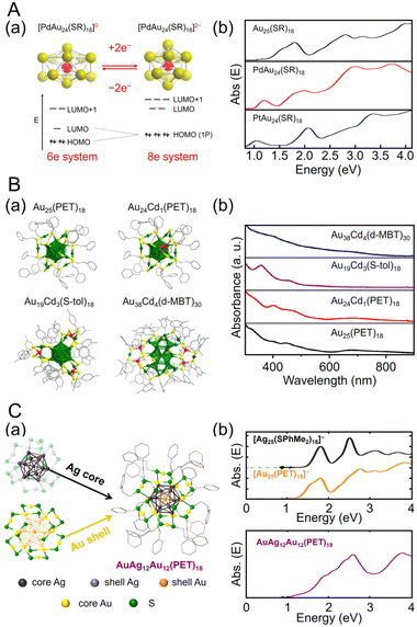 | ||
| Fig. 3 (A) (a) Cartoon depicting Jahn–Teller-like distortion in the core (e.g., PdAu12) predicted for the 6-electron [PdAu24(SR)18]0 (left), which undergoes a structural change to nearly spherical 8-electron [PdAu24(SR)18]2− upon reduction (right). The vertical compression for [PdAu24(SR)18]0 (left) is exaggerated. (b) UV/Vis/NIR absorption spectra of Au25(SC6H13)18 (black), PdAu24(SC6H13)18 (red), and PtAu24(SC6H13)18 (blue) in trichloroethylene. (B) (a) Total crystal structures and (b) UV/Vis absorption spectra of Au25(PET)18, Au24Cd1(PET)18, Au19Cd3(S-tol)18, and Au38Cd4(d-MBT)30. Au, green; Cd, red; S, yellow; C, gray. H atoms are omitted for clarity. (C) (a) Schematic of active-site engineering and crystal structure of the [AgxAu25−x(PET)18]−. (b) UV/vis absorption spectra of the [Ag25(SPhMe2)18]−, [Au25(PET)18]− and [AgxAu25−x(PET)18]− (x = 10–15) in dichloromethane. (A) is reproduced with permission from ref. 187. Copyright 2015 American Chemical Society. (B) is reproduced with permission from ref. 188. Copyright 2021 American Chemical Society. (C) is reproduced with permission from ref. 190. Copyright 2022 American Chemical Society. | ||
Especially among Aun(SR)m applied in CRRs, Cd doping supports high activation. In this case, [Au25(PET)18]− is dissolved in CH3CN, and Cd(NO3)2 is added and stirred/extracted to synthesize Au24Cd1(PET)18 in which one Au atom is replaced by a Cd atom (Fig. 3Ba). Significant differences can be observed in the electronic structure after doping (Fig. 3Bb). In addition, by dissolving Au24Cd1(PET)18 in toluene as a precursor, mixing it with different SR ligands, and adding methanol and stirring, a ligand exchange reaction can be used to synthesize Au24Cd1(TBBT)18 (TBBT = 4-tert-butylbenzenethiolate) and Au24Cd1(d-MBT)18 (d-MBT = 3,5-dimethylbenzenthiolate) from Au24Cd1(PET)18.188 Similarly, Cd-doped Aun(SR)m, such as Au19Cd3(S-tol)18 and Au38Cd4(d-MBT)30 (S-tol = p-toluenethiolate), can be synthesized using Au25(PET)18 and Au44(d-MBT)28 as precursors, respectively.188 In the case of Au24Cd1(PET)18, Cd atoms are substituted for Au atoms on the surface of the Au13 core, but for Au19Cd3(S-tol)18 and Au38Cd4(d-MBT)30, Cd atoms are substituted at the outer staples of the Au13 and Au26 cores, respectively (Fig. 3Ba). These differences can significantly alter the electronic structure (Fig. 3Bb).
Ag can be doped into [Au25(SR)18]− with a relatively large number of substitutions.165,166,170,189 In 2022, Kim, Yoo, and Lee et al., synthesized [AuxAg12−x@Au12(PET)18]− (x = 10–15) with an Au12(PET)18 shell (Fig. 3Ca).190 In this synthesis, they referred to the previously reported synthesis of [Ag25(SPhMe2)18]− (SPhMe2 = 2,4-dimethylbenzenethiolate)191 and alloyed [Au25(PET)18]− by introducing silver acetate (CH3COOAg) during the process. In [AuxAg12−x@Au12(PET)18]−, absorption peaks were observed at 1.9, 2.6, and 3.8 eV (Fig. 3Cb), and SC-XRD revealed that the AuAg12 core was covered by an Au12(PET)18 shell (Fig. 3Ca).
![[thin space (1/6-em)]](https://www.rsc.org/images/entities/char_2009.gif) 195 can be synthesized (Fig. 4Aa). Au38T is relatively unstable and converts to Au38Q, a more stable structure, by heating to approximately 50 °C. Au38Q is composed of two icosahedral Au13 cores connected by sharing an Au3 face, and its electronic structure differs significantly from that of Au38T (Fig. 4Ab). The protected shell of Au38Q consists of the remaining 15 Au atoms and contains six Au2(SR)3 and three Au(SR)2 staples. Furthermore, Au38Q has a pair of enantiomers, also known as Aun(SR)m with chirality.196–198 In 2022, Zhou, Gao, and Zhu et al. synthesized [Au38(SCH2PhtBu)24]0 (SCH2PhtBu = 4-tert-butylbenzylthiolate) using the ligand exchange method, in which 4-tert-butylbenzylthiol is added to Au38Q and stirred.199 They also synthesized Au38(SCH2PhtBu)24 doped with Pt and Pd. In this synthesis, HAuCl4·4H2O and H2PtCl6·6H2O are mixed in THF, and then TOAB is added and stirred. Next, they added 4-tert-butylbenzylthiol and NaBH4 and reacted for 6 h. After washing and separation, [Pt2Au36(SCH2PhtBu)24]0 and [Pt1Au37(SCH2PhtBu)24]0 were obtained (Fig. 4Ba). Although [Au38(SR)24]0 and [Pt2Au36(SR)24]0 have closed-shell electron configurations with 14- and 12-electron superatomic configurations, respectively,200,201 [Pt1Au37(SCH2PhtBu)24]0 has a 13-electron configuration, and electron spin resonance measurements indicate that only [Pt1Au37(SCH2PhtBu)24]0 is magnetic. The optical peaks are blue-shifted with increasing Pt doping, compared with [Au38(SCH2PhtBu)24]0 (Fig. 4Bb).
195 can be synthesized (Fig. 4Aa). Au38T is relatively unstable and converts to Au38Q, a more stable structure, by heating to approximately 50 °C. Au38Q is composed of two icosahedral Au13 cores connected by sharing an Au3 face, and its electronic structure differs significantly from that of Au38T (Fig. 4Ab). The protected shell of Au38Q consists of the remaining 15 Au atoms and contains six Au2(SR)3 and three Au(SR)2 staples. Furthermore, Au38Q has a pair of enantiomers, also known as Aun(SR)m with chirality.196–198 In 2022, Zhou, Gao, and Zhu et al. synthesized [Au38(SCH2PhtBu)24]0 (SCH2PhtBu = 4-tert-butylbenzylthiolate) using the ligand exchange method, in which 4-tert-butylbenzylthiol is added to Au38Q and stirred.199 They also synthesized Au38(SCH2PhtBu)24 doped with Pt and Pd. In this synthesis, HAuCl4·4H2O and H2PtCl6·6H2O are mixed in THF, and then TOAB is added and stirred. Next, they added 4-tert-butylbenzylthiol and NaBH4 and reacted for 6 h. After washing and separation, [Pt2Au36(SCH2PhtBu)24]0 and [Pt1Au37(SCH2PhtBu)24]0 were obtained (Fig. 4Ba). Although [Au38(SR)24]0 and [Pt2Au36(SR)24]0 have closed-shell electron configurations with 14- and 12-electron superatomic configurations, respectively,200,201 [Pt1Au37(SCH2PhtBu)24]0 has a 13-electron configuration, and electron spin resonance measurements indicate that only [Pt1Au37(SCH2PhtBu)24]0 is magnetic. The optical peaks are blue-shifted with increasing Pt doping, compared with [Au38(SCH2PhtBu)24]0 (Fig. 4Bb).
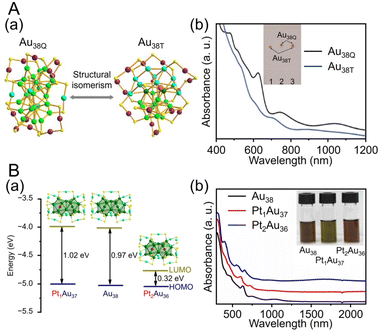 | ||
| Fig. 4 (A) (a) Crystal structures and (b) UV/Vis/NIR absorption spectra of Au38T (blue) and Au38Q (black) in toluene (measurement temperature: 0 °C). (B) (a) Crystal structures and energy band diagrams, and (b) UV/Vis/NIR spectra of [Au38(SCH2PhtBu)24]0, [Pt1Au37(SCH2PhtBu)24]0 and [Pt2Au36(SCH2PhtBu)24]0. The inset is the picture of the three clusters in CHCl3. (A) is reproduced with permission from ref. 195. Copyright 2015 Springer Nature. (B) is reproduced with permission from ref. 199. Copyright 2022 Wiley-VCH GmbH. | ||
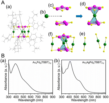 | ||
| Fig. 5 (A) (a) Total structure of the Au4Pd6(TBBT)12. (b) One Au kernel of Au4Pd6. (c) Two Pd3(TBBT)3 staple motifs. (d) AuPd6(TBBT)6. (e) Three Au(TBBT)2 staple motifs. (f) Au4Pd6(TBBT)12 (green, Au; purple, Pd; yellow, S; gray, C; white, H). (B) Experimental UV/Vis/NIR spectra of (a) Au4Pd6(TBBT)12 and (b) Au3AgPd6(TBBT)12. (A) and (B) are reproduced with permission from ref. 202. Copyright 2022 American Chemical Society. | ||
Many studies have reported on Aun(SR)m of different sizes, whose crystal structures are also known. For example, Au18(SR)14,203 Au20(TBBT)16,204 Au21(StBu)15,205 [Au23(SC6H11)16]− (SC6H11 = cyclohexanethiolate),206 Au24(TBBT)20,207 Au28(TBBT)20,208 Au30S(StBu)18,209 Au36(SR)24,210 Au44(TBBT)28,211 Au52(TBBT)32,212 Au92(TBBT)44,213 Au130(p-MBT)50 (p-MBT = 4-methylbenzenethiolate),214 and Au144(SR)60![[thin space (1/6-em)]](https://www.rsc.org/images/entities/char_2009.gif) 215,216 have been reported, as well as many other Aun(SR)m. Notably, their systematic syntheses and size dependence have also been investigated.32–36 In 2017, Ramakrishna and Lee et al. used SC6H13 as a ligand to synthesize Au25(SC6H13)18, Au38(SC6H13)24, Au67(SC6H13)35, Au102(SC6H13)44, Au144(SC6H13)60, and Au333(SC6H13)79.217 Their chemical compositions were confirmed by matrix-assisted laser desorption/ionization mass spectrometry (MALDI-MS) (Fig. 6Aa). Furthermore, these Aun(SR)m exhibit size-dependent optical properties (Fig. 6Ab), and the optical gap of the electronic transitions decreases as the cluster size increases (Fig. 6B).
215,216 have been reported, as well as many other Aun(SR)m. Notably, their systematic syntheses and size dependence have also been investigated.32–36 In 2017, Ramakrishna and Lee et al. used SC6H13 as a ligand to synthesize Au25(SC6H13)18, Au38(SC6H13)24, Au67(SC6H13)35, Au102(SC6H13)44, Au144(SC6H13)60, and Au333(SC6H13)79.217 Their chemical compositions were confirmed by matrix-assisted laser desorption/ionization mass spectrometry (MALDI-MS) (Fig. 6Aa). Furthermore, these Aun(SR)m exhibit size-dependent optical properties (Fig. 6Ab), and the optical gap of the electronic transitions decreases as the cluster size increases (Fig. 6B).
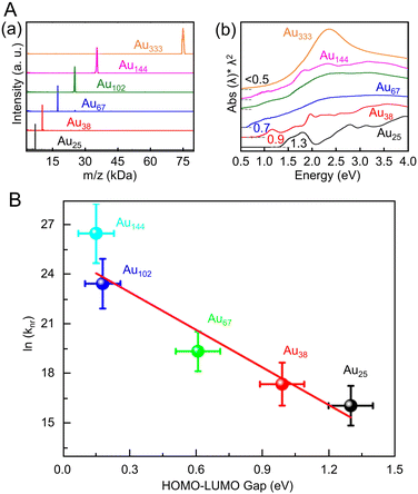 | ||
| Fig. 6 (A) (a) MALDI mass spectra and (b) UV/Vis/NIR absorption spectra of Au25, Au38, Au67, Au102, Au144, and Au333 clusters. The absorption spectra of clusters were obtained in tetrachloroethylene and were offset for clarity. (B) Plot of ln(knr) versus HOMO–LUMO gap for Aun(SR)m. The solid line is the best fit straight line for data (Au25–Au144). (A) and (B) are reproduced with permission from ref. 217. Copyright 2017 American Chemical Society. | ||
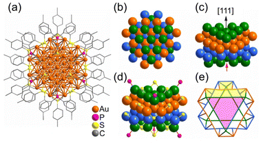 | ||
| Fig. 7 (a) Anisotropic growth of the Au fcc lattice into a triangle prism in [Au55(p-MBT)24(PPh3)6]3+. The Au atom packing of four layers (green, orange, light blue and green) stacked along the [111] direction in an A–B–C–A manner. (b) Top view; (c) side view; (d) the ligand binding positions; (e) simplified facets (Au green/orange/light-blue, S yellow, P pink). Note: the red arrow refers to the missing Au atom in the real Au55 cluster. These figures are reproduced with permission from ref. 233. Copyright 2021 Wiley-VCH GmbH. | ||
![[triple bond, length as m-dash]](https://www.rsc.org/images/entities/char_e002.gif) CR,23,234–236 NHC,237–241 and nitrogen donor ligands242 have been reported in recent years. In 2016, Wang and Zheng et al. synthesized Au34Ag28(C
CR,23,234–236 NHC,237–241 and nitrogen donor ligands242 have been reported in recent years. In 2016, Wang and Zheng et al. synthesized Au34Ag28(C![[triple bond, length as m-dash]](https://www.rsc.org/images/entities/char_e002.gif) CPh)34 by adding silver acetate (CH3COOAg) and tert-butylamineborane complexes to a solution containing Au precursors and phenylacetylene (HC
CPh)34 by adding silver acetate (CH3COOAg) and tert-butylamineborane complexes to a solution containing Au precursors and phenylacetylene (HC![[triple bond, length as m-dash]](https://www.rsc.org/images/entities/char_e002.gif) CPh) while stirring. The NCs function as highly active catalysts for the hydrolytic oxidation of triethylsilanes by removing the ligands more readily at relatively low temperatures than the previously reported Aun(SR)m.243 In 2021, Pei and Tang et al. synthesized an alloy cluster of Ag and Cu, [Ag9Cu6(C6H9)12]+, and an alloy cluster of Au and Ag, [Au7Ag8(C
CPh) while stirring. The NCs function as highly active catalysts for the hydrolytic oxidation of triethylsilanes by removing the ligands more readily at relatively low temperatures than the previously reported Aun(SR)m.243 In 2021, Pei and Tang et al. synthesized an alloy cluster of Ag and Cu, [Ag9Cu6(C6H9)12]+, and an alloy cluster of Au and Ag, [Au7Ag8(C![[triple bond, length as m-dash]](https://www.rsc.org/images/entities/char_e002.gif) CtBu)12]+ (HC
CtBu)12]+ (HC![[triple bond, length as m-dash]](https://www.rsc.org/images/entities/char_e002.gif) CtBu = tert-butylacetylene), using antigalvanic reactions.244 These two alloy clusters have body-centered cubic (bcc) structures and exhibit different optical properties (Fig. 8Aa). The differences in optical properties were attributed to slightly different structures of the M1 kernel (M = Ag or Au), M6 octahedron (M = Cu or Au), and Ag8 cube. Subsequently, in 2022, Q. Tang and Z. Tang et al. synthesized [Au2Ag8Cu5(C
CtBu = tert-butylacetylene), using antigalvanic reactions.244 These two alloy clusters have body-centered cubic (bcc) structures and exhibit different optical properties (Fig. 8Aa). The differences in optical properties were attributed to slightly different structures of the M1 kernel (M = Ag or Au), M6 octahedron (M = Cu or Au), and Ag8 cube. Subsequently, in 2022, Q. Tang and Z. Tang et al. synthesized [Au2Ag8Cu5(C![[triple bond, length as m-dash]](https://www.rsc.org/images/entities/char_e002.gif) CtBu)12]+, an alloy cluster composed of Au, Ag, and Cu, by adding chlorodimethylsulfide gold(I) ((CH3)2SAuCl) as an Au precursor to [Ag9Cu6(C6H9)12]+.245 Although many reports have focused on the synthesis of alloy NCs,38 [Au2Ag8Cu5(C
CtBu)12]+, an alloy cluster composed of Au, Ag, and Cu, by adding chlorodimethylsulfide gold(I) ((CH3)2SAuCl) as an Au precursor to [Ag9Cu6(C6H9)12]+.245 Although many reports have focused on the synthesis of alloy NCs,38 [Au2Ag8Cu5(C![[triple bond, length as m-dash]](https://www.rsc.org/images/entities/char_e002.gif) CtBu)12]+ is the first report of a trimetal NC protected with only a C
CtBu)12]+ is the first report of a trimetal NC protected with only a C![[triple bond, length as m-dash]](https://www.rsc.org/images/entities/char_e002.gif) CR ligand. The optical absorption spectrum of [Au2Ag8Cu5(C
CR ligand. The optical absorption spectrum of [Au2Ag8Cu5(C![[triple bond, length as m-dash]](https://www.rsc.org/images/entities/char_e002.gif) CtBu)12]+ reveals a completely different electronic structure compared with those previously described for [Ag9Cu6(C6H9)12]+ and [Au7Ag8(C
CtBu)12]+ reveals a completely different electronic structure compared with those previously described for [Ag9Cu6(C6H9)12]+ and [Au7Ag8(C![[triple bond, length as m-dash]](https://www.rsc.org/images/entities/char_e002.gif) CtBu)12]+ (Fig. 8A). Photoluminescence measurements showed that [Au2Ag8Cu5(C
CtBu)12]+ (Fig. 8A). Photoluminescence measurements showed that [Au2Ag8Cu5(C![[triple bond, length as m-dash]](https://www.rsc.org/images/entities/char_e002.gif) CtBu)12]+ has stronger emission than the other two NCs in the near-infrared region (Fig. 8Ab). [Au2Ag8Cu5(C
CtBu)12]+ has stronger emission than the other two NCs in the near-infrared region (Fig. 8Ab). [Au2Ag8Cu5(C![[triple bond, length as m-dash]](https://www.rsc.org/images/entities/char_e002.gif) CtBu)12]+ also consists of an M@M8@M6 metal core, similar to the other two NCs, but each NC exhibits different CRR selectivity (see section 3).
CtBu)12]+ also consists of an M@M8@M6 metal core, similar to the other two NCs, but each NC exhibits different CRR selectivity (see section 3).
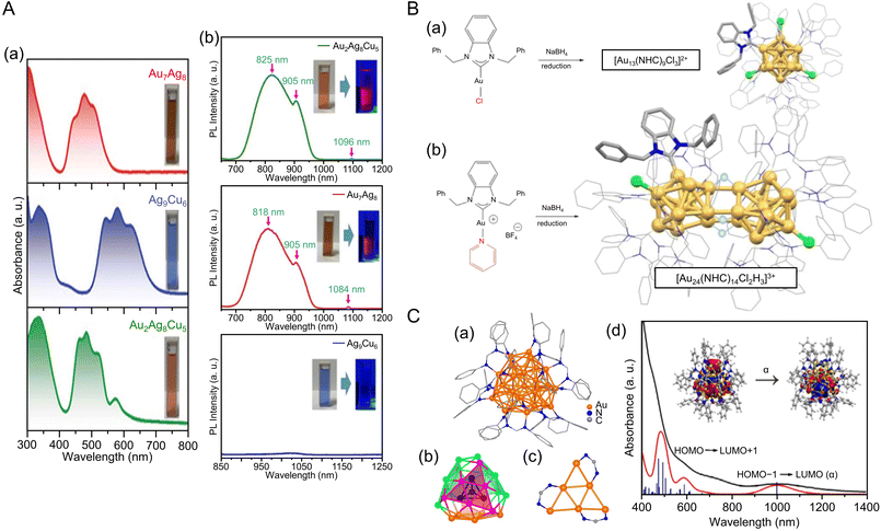 | ||
Fig. 8 (A) (a)Absorbance spectra of [Au7Ag8(C![[triple bond, length as m-dash]](https://www.rsc.org/images/entities/char_e002.gif) CtBu)12]+, [Ag9Cu6(C6H9)12]+ and [Au2Ag8Cu5(C CtBu)12]+, [Ag9Cu6(C6H9)12]+ and [Au2Ag8Cu5(C![[triple bond, length as m-dash]](https://www.rsc.org/images/entities/char_e002.gif) CtBu)12]+. (b) The emission spectra of [Au7Ag8(C CtBu)12]+. (b) The emission spectra of [Au7Ag8(C![[triple bond, length as m-dash]](https://www.rsc.org/images/entities/char_e002.gif) CtBu)12]+ (λex = 482 nm), [Ag9Cu6(C6H9)12]+ (λex = 580 nm) and [Au2Ag8Cu5(C CtBu)12]+ (λex = 482 nm), [Ag9Cu6(C6H9)12]+ (λex = 580 nm) and [Au2Ag8Cu5(C![[triple bond, length as m-dash]](https://www.rsc.org/images/entities/char_e002.gif) CtBu)12]+ (λex = 490 nm) in dichloromethane. Inset: photographs of the three NCs in dichloromethane under room light (left) and 365 nm UV-light (right), respectively. (B) Production of different NHC-stabilized Au clusters depending on the ancillary ligand (halide or pyridine). (a) Use of halide ligands gives typical Au13 clusters ([Au13(NHC)9Cl3]2+), while (b) labile ancillary ligand leads to hydride bridged Au24 clusters ([Au24(NHC)14Cl2H3]3+). (C) (a) The overall structure of [Au28(Ph-form)12]2+. (b) The T symmetrical Au28 kernel with concentric tetrahedral Au4 core (black) and truncated tetrahedron Au24 shell divided into four {111} faces. (c) The bridge mode of formamidinate ligands; all Ph rings are omitted for clarity. (d) The experimental (black) and simulated (red) absorption spectra of Au28. (Inset) The NTO picture of the first absorption peak. (A) is reproduced with permission from ref. 245. Copyright 2022 Royal Society of Chemistry. (B) is reproduced with permission from ref. 249. Copyright 2022 American Chemical Society. (C) is reproduced with permission from ref. 250. Copyright 2021 Wiley-VCH GmbH. CtBu)12]+ (λex = 490 nm) in dichloromethane. Inset: photographs of the three NCs in dichloromethane under room light (left) and 365 nm UV-light (right), respectively. (B) Production of different NHC-stabilized Au clusters depending on the ancillary ligand (halide or pyridine). (a) Use of halide ligands gives typical Au13 clusters ([Au13(NHC)9Cl3]2+), while (b) labile ancillary ligand leads to hydride bridged Au24 clusters ([Au24(NHC)14Cl2H3]3+). (C) (a) The overall structure of [Au28(Ph-form)12]2+. (b) The T symmetrical Au28 kernel with concentric tetrahedral Au4 core (black) and truncated tetrahedron Au24 shell divided into four {111} faces. (c) The bridge mode of formamidinate ligands; all Ph rings are omitted for clarity. (d) The experimental (black) and simulated (red) absorption spectra of Au28. (Inset) The NTO picture of the first absorption peak. (A) is reproduced with permission from ref. 245. Copyright 2022 Royal Society of Chemistry. (B) is reproduced with permission from ref. 249. Copyright 2022 American Chemical Society. (C) is reproduced with permission from ref. 250. Copyright 2021 Wiley-VCH GmbH. | ||
Au NCs using NHC as a ligand are generally synthesized by the reduction of precursors, such as NHC–Au(I)–X complexes (X = Cl, Br),246,247 using NaBH4. In 2022, Dinh, Tsukuda, Häkkinen, and Crudden et al. dissolved the [NHC–Au–Pyr]+ complex (Pry = pyridine)248 in toluene, added NaBH4, stirred the mixture, separated the products, and then purified them by chromatography to obtain [Au24(NHC)14Cl2H3]3+ (Fig. 8B).249 [Au24(NHC)14Cl2H3]3+ consists of two icosahedral Au12 cores with distorted structures and three bridging hydride ligands, and the hydride ligands are coordinated to the Au13 core, which has been confirmed by SC-XRD, ESI-MS, and nuclear magnetic resonance (NMR) spectroscopy.
Studies have also reported on amidinate-protected Au NCs. In 2021, Wang et al. mixed (CH3)2SAuCl, N,N′-diphenylformamidinate (Ph-form), and sodium trifluoromethanesulfonate (NaOTf) in chloroform, stirred, and then added sodium methanolate (MeONa). Next, they synthesized [Au28(Ph-form)12]2+ by adding NaBH4 and vigorously stirring the mixture under various temperature conditions.250 The [Au28(Ph-form)12]2+ exhibited high stability owing to its superatomic configuration of 1S21P62S21D4, and theoretical calculations reproduced the measured electronic structure (Fig. 8C).
As mentioned above, numerous synthetic examples of Au NCs protected by organic ligands, such as SR, phosphine, C![[triple bond, length as m-dash]](https://www.rsc.org/images/entities/char_e002.gif) CR, and NHC, have been reported. Moreover, many of the Au NCs described in this section have been applied in electrochemical CRRs, which are described in detail in section 3.3.
CR, and NHC, have been reported. Moreover, many of the Au NCs described in this section have been applied in electrochemical CRRs, which are described in detail in section 3.3.
2.2 Synthesis of silver nanocluster
Ag NCs, which are mainly composed of Ag, have been widely studied in recent years because of their relatively high quantum yields in terms of luminescence.43 Similar to Au NCs, Ag NCs can be synthesized with atomic precision using ligands such as SR, phosphine, and C![[triple bond, length as m-dash]](https://www.rsc.org/images/entities/char_e002.gif) CR. In this section, we describe several examples.
CR. In this section, we describe several examples.
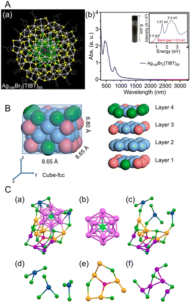 | ||
| Fig. 9 (A) (a) Top views of the total structure of the Ag146Br2(TIBT)80. Color labels: dark gray/green = Ag, yellow = S, purple = Br; the carbon tails are shown in wire-frame mode. (b) UV/Vis/NIR absorption spectra of the Ag146Br2(TIBT)80 in CCl4. Inset: Photograph of 5.08 g of Ag146Br2(TIBT)80 in a vial, and the spectrum plotted on the photon energy scale (the y-axis is transformed from the wavelength scale spectrum by Abs × λ2 to preserve the oscillator strength). (B) Size and slicing of the M50 kernel in [Ag39Cu11(SC7H7O)32]2+. Color codes: pure blue, Ag; pink, Cu; green, Ag/Cu, yellow, S; red, O; gray, C. For clarity, all H atoms are omitted. (C) Structural analysis of [AuAg26(S-Adm)18S]−. (a) The framework structure of AuAg26, (b) the AuAg12 icosahedron kernel, (c) the Ag14(SR)18S open shell, (d) three-AgS3 motif, (e) Ag6(SR)3S motif, (f) Ag5(SR)6 motif. Color code: azure, Au; magenta/blue/orange/violet, Ag; red, single S atom; green, other S. The C and H atoms are omitted for clarity. (A) is reproduced with permission from ref. 253. Copyright 2018 American Chemical Society. (B) is reproduced with permission from ref. 254. Copyright 2023 American Chemical Society. (C) is reproduced with permission from ref. 255. Copyright 2020 American Chemical Society. | ||
Alloy NCs based on Agn(SR)m were also reported. In 2023, Wang, Yan, and Wu et al. synthesized fcc-structured bimetallic NCs ([Ag41Cu9(SC7H7O)32]2+) using a one-pot method and achieved surface substitution of alloy clusters with an increased Cu/Ag atomic ratio ([Ag39Cu11(SC7H7O)32]2+), without changing the reaction conditions.254 In this synthesis, AgNO3 and copper(II) acetylacetonate (Cu(acac)2) were added as precursors in the appropriate ratios for the respective NCs, 3-methoxythiophenol was added and stirred, and the mixture was co-reduced with NaBH4. These NCs have an fcc structure consisting of four layers, with different atoms exposed on the surface depending on the Ag/Cu ratio (Fig. 9B). In 2021, Liu and Huang et al. synthesized S-Adm (1-adamantanethiolate)-protected bimetallic NCs ([AuAg26(S-Adm)18S]−) using a one-pot method.255 For this synthesis, AgNO3 and AuCl3 solutions were mixed, and 1-adamantanethiol was added to the mixture. Then, PPh3, tetraphenylphosphonium bromide (PPh4Br), and NaBH4 were added and kept to form [AuAg26(S-Adm)18S]−, in which the Ag12 core covers the central Au atom and the Ag14 shell covers the core (Fig. 9C). These differ from common 25-mer NCs in that the outer Ag14 shell has a large open shell structure consisting of three different motifs.
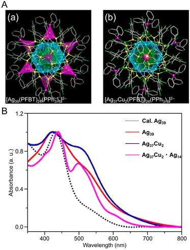 | ||
| Fig. 10 (A) Overall structure of (a) [Ag39(PFBT)24(PPh3)8]2− and (b) [Ag37Cu2(PFBT)24(PPh3)8]2−. (B) UV/Vis absorbance spectra of [Ag39(PFBT)24(PPh3)8]2− (red), [Ag37Cu2(PFBT)24(PPh3)8]2− (blue), and [Ag37Cu2(PFBT)24(PPh3)8]2−·[Ag14(PFBT)6(PPh3)8] (purple) in solution. (A) and (B) are reproduced with permission from ref. 256. Copyright 2022 American Chemical Society. | ||
![[triple bond, length as m-dash]](https://www.rsc.org/images/entities/char_e002.gif) CR ligands, similar to Au NCs. In 2017, Li and Zhang et al. reported the synthesis of [Ag74(C
CR ligands, similar to Au NCs. In 2017, Li and Zhang et al. reported the synthesis of [Ag74(C![[triple bond, length as m-dash]](https://www.rsc.org/images/entities/char_e002.gif) CPh)44]2+.257 In this synthesis, 1,3-bis(diphenyphosphino)propane (DPPP) and PhC
CPh)44]2+.257 In this synthesis, 1,3-bis(diphenyphosphino)propane (DPPP) and PhC![[triple bond, length as m-dash]](https://www.rsc.org/images/entities/char_e002.gif) CH were first added to a solution of dissolved AgNO3 and stirred, and then NaBH4 was added. In addition to C
CH were first added to a solution of dissolved AgNO3 and stirred, and then NaBH4 was added. In addition to C![[triple bond, length as m-dash]](https://www.rsc.org/images/entities/char_e002.gif) CPh ligands, many reports have considered the synthesis of Ag NCs protected by C
CPh ligands, many reports have considered the synthesis of Ag NCs protected by C![[triple bond, length as m-dash]](https://www.rsc.org/images/entities/char_e002.gif) CtBu, which is a C
CtBu, which is a C![[triple bond, length as m-dash]](https://www.rsc.org/images/entities/char_e002.gif) CR ligand with a tert-butyl group. In 2021, Tang, Jin, and Tang et al. reported the synthesis of C
CR ligand with a tert-butyl group. In 2021, Tang, Jin, and Tang et al. reported the synthesis of C![[triple bond, length as m-dash]](https://www.rsc.org/images/entities/char_e002.gif) CtBu-protected Ag15 NCs ([Ag15(C
CtBu-protected Ag15 NCs ([Ag15(C![[triple bond, length as m-dash]](https://www.rsc.org/images/entities/char_e002.gif) CtBu)12]+) and their application in CRRs.258 In this synthesis, HC
CtBu)12]+) and their application in CRRs.258 In this synthesis, HC![[triple bond, length as m-dash]](https://www.rsc.org/images/entities/char_e002.gif) CtBu, MeONa, and sodium cyanoborohydride (NaBH3CN) are first added to a silver trifluoroacetate solution and stirred. Subsequently, [Ag15(C
CtBu, MeONa, and sodium cyanoborohydride (NaBH3CN) are first added to a silver trifluoroacetate solution and stirred. Subsequently, [Ag15(C![[triple bond, length as m-dash]](https://www.rsc.org/images/entities/char_e002.gif) CtBu)12]+ is synthesized by cooling and extraction with a mixture of dichloromethane and CH3CN (Fig. 11A). The optical absorption spectrum of [Ag15(C
CtBu)12]+ is synthesized by cooling and extraction with a mixture of dichloromethane and CH3CN (Fig. 11A). The optical absorption spectrum of [Ag15(C![[triple bond, length as m-dash]](https://www.rsc.org/images/entities/char_e002.gif) CtBu)12]+ shows five peaks at 360, 480, 508, 542, and 580 nm (Fig. 11B). Additionally, [Ag15(C
CtBu)12]+ shows five peaks at 360, 480, 508, 542, and 580 nm (Fig. 11B). Additionally, [Ag15(C![[triple bond, length as m-dash]](https://www.rsc.org/images/entities/char_e002.gif) CtBu)12]+ has a core/shell structure of Ag@Ag8@Ag6, with an irregularly shaped cubic Ag8 in the second layer and an octahedron of Ag6 in the outermost shell (Fig. 11A). In 2022, Tang, Wang and Tang et al. reported the synthesis of Ag32(C
CtBu)12]+ has a core/shell structure of Ag@Ag8@Ag6, with an irregularly shaped cubic Ag8 in the second layer and an octahedron of Ag6 in the outermost shell (Fig. 11A). In 2022, Tang, Wang and Tang et al. reported the synthesis of Ag32(C![[triple bond, length as m-dash]](https://www.rsc.org/images/entities/char_e002.gif) CPh(CF3)2)24 (HC
CPh(CF3)2)24 (HC![[triple bond, length as m-dash]](https://www.rsc.org/images/entities/char_e002.gif) CPh(CF3)2 = 3,5-bis(trifluoromethyl)phenylacetylene) based on Chen's and Tang's synthetic method259 for Au36(C
CPh(CF3)2 = 3,5-bis(trifluoromethyl)phenylacetylene) based on Chen's and Tang's synthetic method259 for Au36(C![[triple bond, length as m-dash]](https://www.rsc.org/images/entities/char_e002.gif) CPh)24 reported in 2020 (Fig. 12A).260 In this synthesis, MeONa, HC
CPh)24 reported in 2020 (Fig. 12A).260 In this synthesis, MeONa, HC![[triple bond, length as m-dash]](https://www.rsc.org/images/entities/char_e002.gif) CPh(CF3)2, and NaBH3CN are added to a solution of silver trifluoroacetate (CF3COOAg) and stirred. The purple-black crystals are synthesized by centrifuging the mixed solution to remove the precipitate, followed by washing/extraction. Ag32(C
CPh(CF3)2, and NaBH3CN are added to a solution of silver trifluoroacetate (CF3COOAg) and stirred. The purple-black crystals are synthesized by centrifuging the mixed solution to remove the precipitate, followed by washing/extraction. Ag32(C![[triple bond, length as m-dash]](https://www.rsc.org/images/entities/char_e002.gif) CPh(CF3)2)2 has an Ag5 core and Ag5@Ag12 kernel in the center, according to SC-XRD, and the surface is protected by four different ligands (Fig. 12A). The optical absorption spectra reveal peaks at 518 and 656 nm (Fig. 12B).
CPh(CF3)2)2 has an Ag5 core and Ag5@Ag12 kernel in the center, according to SC-XRD, and the surface is protected by four different ligands (Fig. 12A). The optical absorption spectra reveal peaks at 518 and 656 nm (Fig. 12B).
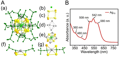 | ||
Fig. 11 (A) (a) The overall structure of [Ag15(C![[triple bond, length as m-dash]](https://www.rsc.org/images/entities/char_e002.gif) CtBu)12]+. (b)–(d) Shell-by-shell representations of the metal framework, Ag@Ag8@Ag6 (note that there is no bond between the orange silver atom and the adjacent three silver atoms (yellow) in the frame of the Ag8 cube; similarly, the six capping Ag atoms form an octahedron with no bonds between them). (e) Metal framework of [Ag15(C CtBu)12]+. (b)–(d) Shell-by-shell representations of the metal framework, Ag@Ag8@Ag6 (note that there is no bond between the orange silver atom and the adjacent three silver atoms (yellow) in the frame of the Ag8 cube; similarly, the six capping Ag atoms form an octahedron with no bonds between them). (e) Metal framework of [Ag15(C![[triple bond, length as m-dash]](https://www.rsc.org/images/entities/char_e002.gif) CtBu)12]+. (f) and (g) Side and top views of the six Ag(C CtBu)12]+. (f) and (g) Side and top views of the six Ag(C![[triple bond, length as m-dash]](https://www.rsc.org/images/entities/char_e002.gif) CtBu)2 staple units capping a silver square of the Ag8 cube. Ag gray/yellow/orange/light-green, C dark green; all hydrogen atoms are omitted for clarity. (B) UV/Vis absorbance spectrum of [Ag15(C CtBu)2 staple units capping a silver square of the Ag8 cube. Ag gray/yellow/orange/light-green, C dark green; all hydrogen atoms are omitted for clarity. (B) UV/Vis absorbance spectrum of [Ag15(C![[triple bond, length as m-dash]](https://www.rsc.org/images/entities/char_e002.gif) CtBu)12]+. (A) and (B) are reproduced with permission from ref. 258. Copyright 2021 Wiley-VCH GmbH. CtBu)12]+. (A) and (B) are reproduced with permission from ref. 258. Copyright 2021 Wiley-VCH GmbH. | ||
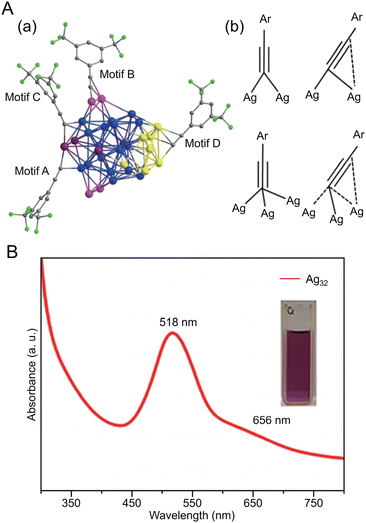 | ||
Fig. 12 (A) (a) Four types of ligand–metal bonding motifs in Ag32(C![[triple bond, length as m-dash]](https://www.rsc.org/images/entities/char_e002.gif) CPh(CF3)2)24. (b) Four motifs in Ag32(C CPh(CF3)2)24. (b) Four motifs in Ag32(C![[triple bond, length as m-dash]](https://www.rsc.org/images/entities/char_e002.gif) CPh(CF3)2)24 coordination modes for alkynyl ligands. Color code: Ag, blue/pink/purple/yellow; C, gray; and F, green. (B) UV/Vis absorbance spectrum of Ag32(C CPh(CF3)2)24 coordination modes for alkynyl ligands. Color code: Ag, blue/pink/purple/yellow; C, gray; and F, green. (B) UV/Vis absorbance spectrum of Ag32(C![[triple bond, length as m-dash]](https://www.rsc.org/images/entities/char_e002.gif) CPh(CF3)2)24. Inset: photograph of the cluster in CH2Cl2. (A) and (B) are reproduced with permission from ref. 260. Copyright 2022 Springer Nature. CPh(CF3)2)24. Inset: photograph of the cluster in CH2Cl2. (A) and (B) are reproduced with permission from ref. 260. Copyright 2022 Springer Nature. | ||
Many examples of Ag-based alloy NCs protected by C![[triple bond, length as m-dash]](https://www.rsc.org/images/entities/char_e002.gif) CR have also been reported. In 2021, Pei and Tang et al. reported the synthesis of an Ag–Cu alloy cluster ([Ag9Cu6(C
CR have also been reported. In 2021, Pei and Tang et al. reported the synthesis of an Ag–Cu alloy cluster ([Ag9Cu6(C![[triple bond, length as m-dash]](https://www.rsc.org/images/entities/char_e002.gif) CtBu)12]+) (Fig. 13A).244 In this synthesis, tBuC
CtBu)12]+) (Fig. 13A).244 In this synthesis, tBuC![[triple bond, length as m-dash]](https://www.rsc.org/images/entities/char_e002.gif) CAg was used as the silver precursor, and bis(triphenylphosphine)copper borohydride ((PPh3)2CuBH4) was used as the copper precursor. First, tBuC
CAg was used as the silver precursor, and bis(triphenylphosphine)copper borohydride ((PPh3)2CuBH4) was used as the copper precursor. First, tBuC![[triple bond, length as m-dash]](https://www.rsc.org/images/entities/char_e002.gif) CAg was mixed with sodium hexafluoroantimonate (NaSbF6), to which (PPh3)2CuBH4 was added, and [Ag9Cu6(C
CAg was mixed with sodium hexafluoroantimonate (NaSbF6), to which (PPh3)2CuBH4 was added, and [Ag9Cu6(C![[triple bond, length as m-dash]](https://www.rsc.org/images/entities/char_e002.gif) CtBu)12]+ was obtained by stirring and reducing the mixture in the dark. Notably, [Ag8Au7(C
CtBu)12]+ was obtained by stirring and reducing the mixture in the dark. Notably, [Ag8Au7(C![[triple bond, length as m-dash]](https://www.rsc.org/images/entities/char_e002.gif) CtBu)12]+, which has a similar geometric structure to [Ag9Cu6(C
CtBu)12]+, which has a similar geometric structure to [Ag9Cu6(C![[triple bond, length as m-dash]](https://www.rsc.org/images/entities/char_e002.gif) CtBu)12]+, can also be synthesized.261 Both NCs are composed of an M1 kernel@Ag8 cube@M6 octahedral structure with a bcc basis (Fig. 13A), but they have slightly different geometric structures depending on the atomic diameters and argentophilic Ag–Ag interaction (Fig. 13B), which affect their optical properties and stability. In 2017, Mizuta et al. reported the synthesis of Pt5Ag22(C
CtBu)12]+, can also be synthesized.261 Both NCs are composed of an M1 kernel@Ag8 cube@M6 octahedral structure with a bcc basis (Fig. 13A), but they have slightly different geometric structures depending on the atomic diameters and argentophilic Ag–Ag interaction (Fig. 13B), which affect their optical properties and stability. In 2017, Mizuta et al. reported the synthesis of Pt5Ag22(C![[triple bond, length as m-dash]](https://www.rsc.org/images/entities/char_e002.gif) CPh)32, obtained by mixing PhC
CPh)32, obtained by mixing PhC![[triple bond, length as m-dash]](https://www.rsc.org/images/entities/char_e002.gif) CAg and H2PtCl6·6H2O, and then adding NaBH4 and stirring in the dark.262 In 2022, Tang, Hwang and Hyeon et al. synthesized an alloy NC of Ag and Cu co-protected by C
CAg and H2PtCl6·6H2O, and then adding NaBH4 and stirring in the dark.262 In 2022, Tang, Hwang and Hyeon et al. synthesized an alloy NC of Ag and Cu co-protected by C![[triple bond, length as m-dash]](https://www.rsc.org/images/entities/char_e002.gif) CPh(CF3)2 and DPPE ([Ag15Cu6(C
CPh(CF3)2 and DPPE ([Ag15Cu6(C![[triple bond, length as m-dash]](https://www.rsc.org/images/entities/char_e002.gif) CPh(CF3)2)18(DPPE)2]−).263 In this synthesis, a silver complex and C
CPh(CF3)2)18(DPPE)2]−).263 In this synthesis, a silver complex and C![[triple bond, length as m-dash]](https://www.rsc.org/images/entities/char_e002.gif) CPh(CF3)2 ligand were stirred with (PPh3)2CuBH4 as a Cu precursor, then washed and extracted from the organic phase, which produced black crystals. The structure of [Ag15Cu6(C
CPh(CF3)2 ligand were stirred with (PPh3)2CuBH4 as a Cu precursor, then washed and extracted from the organic phase, which produced black crystals. The structure of [Ag15Cu6(C![[triple bond, length as m-dash]](https://www.rsc.org/images/entities/char_e002.gif) CPh(CF3)2)18(DPPE)2]− is composed of three layers, Ag@Ag8@Ag2Cu4 (Fig. 13C), with a single Ag atom at the center, followed by an Ag8 cube in the second layer and an Ag2Cu4 octahedron in the third layer, with two Ag2(DPPE) capping the Ag–Cu or Ag–Ag interactions to form [Ag15Cu6(C
CPh(CF3)2)18(DPPE)2]− is composed of three layers, Ag@Ag8@Ag2Cu4 (Fig. 13C), with a single Ag atom at the center, followed by an Ag8 cube in the second layer and an Ag2Cu4 octahedron in the third layer, with two Ag2(DPPE) capping the Ag–Cu or Ag–Ag interactions to form [Ag15Cu6(C![[triple bond, length as m-dash]](https://www.rsc.org/images/entities/char_e002.gif) CPh(CF3)2)18(DPPE)2]− (Fig. 13C).
CPh(CF3)2)18(DPPE)2]− (Fig. 13C).
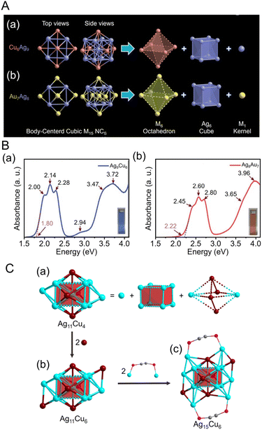 | ||
Fig. 13 (A) Anatomy of (a) [Ag9Cu6(C![[triple bond, length as m-dash]](https://www.rsc.org/images/entities/char_e002.gif) CtBu)12]+ and (b) [Ag8Au7(C CtBu)12]+ and (b) [Ag8Au7(C![[triple bond, length as m-dash]](https://www.rsc.org/images/entities/char_e002.gif) CtBu)12]+. Color legend: Au, yellow; Ag, purple; Cu, orange. (B) Experimental absorbance spectra plotted in the energy axis of (a) [Ag9Cu6(C CtBu)12]+. Color legend: Au, yellow; Ag, purple; Cu, orange. (B) Experimental absorbance spectra plotted in the energy axis of (a) [Ag9Cu6(C![[triple bond, length as m-dash]](https://www.rsc.org/images/entities/char_e002.gif) CtBu)12]+ and (b) [Ag8Au7(C CtBu)12]+ and (b) [Ag8Au7(C![[triple bond, length as m-dash]](https://www.rsc.org/images/entities/char_e002.gif) CtBu)12]+. (C) Structure analysis of the [Ag15Cu6(C CtBu)12]+. (C) Structure analysis of the [Ag15Cu6(C![[triple bond, length as m-dash]](https://www.rsc.org/images/entities/char_e002.gif) CPh(CF3)2)18(DPPE)2]−. (a) Structure anatomy of the Ag11Cu4 metal core. (b) Capping of two opposite Ag3 faces of the Ag11Cu4 core forms the structure of Ag11Cu6. (c) Stabilization of the Ag11Cu6 metal framework by two Ag2DPPE motifs forms the structure of [Ag15Cu6(C CPh(CF3)2)18(DPPE)2]−. (a) Structure anatomy of the Ag11Cu4 metal core. (b) Capping of two opposite Ag3 faces of the Ag11Cu4 core forms the structure of Ag11Cu6. (c) Stabilization of the Ag11Cu6 metal framework by two Ag2DPPE motifs forms the structure of [Ag15Cu6(C![[triple bond, length as m-dash]](https://www.rsc.org/images/entities/char_e002.gif) CPh(CF3)2)18(DPPE)2]−. Color legend: turquoise, Ag; dark red, Cu; pink, P; gray, C. (A) and (B) are reproduced with permission from ref. 244. Copyright 2021 Royal Society of Chemistry. (C) is reproduced with permission from ref. 263. Copyright 2022 American Chemical Society. CPh(CF3)2)18(DPPE)2]−. Color legend: turquoise, Ag; dark red, Cu; pink, P; gray, C. (A) and (B) are reproduced with permission from ref. 244. Copyright 2021 Royal Society of Chemistry. (C) is reproduced with permission from ref. 263. Copyright 2022 American Chemical Society. | ||
In addition to ligand-protected Ag NCs, many reports have focused on the synthesis of Ag NCs using anions, such as halide ions, chalcogenide ions, oxoanions, and polyoxometalates (POMs), as templates.264,265 In 2022, Liu et al. used a solvothermal reaction to synthesize POM-templated Ag NCs (Ag49Mo16) protected by six thiacalix[4]arenes (TC4A).266 In this synthesis, TC4A was mixed with iPrSAg, CH3COOAg, and ammonium molybdate tetrahydrate ((NH4)6Mo7O24·4H2O), and then triethylamine was added dropwise. After that, light brown crystals were obtained by subjecting the mixture to heat treatment.
As mentioned above, many synthetic examples of Ag NCs protected by organic ligands, such as SR, phosphine, C![[triple bond, length as m-dash]](https://www.rsc.org/images/entities/char_e002.gif) CR, and template types, have been reported. These Ag NCs are also expected to be applied in electrochemical CRRs. In section 3.4, we describe CRRs using mainly the Ag NCs introduced in this section.
CR, and template types, have been reported. These Ag NCs are also expected to be applied in electrochemical CRRs. In section 3.4, we describe CRRs using mainly the Ag NCs introduced in this section.
2.3 Synthesis of copper nanocluster
Cu is more abundant than Au and Ag, and thus Cu-based nanomaterials have advantages such as low environmental burden and low cost. Furthermore, Cu-based catalysts have the appropriate adsorption energy for CO2 and exhibit promising CRR activity, with the ability to produce a variety of organic products from CO2. Moreover, Cu NCs can be synthesized with atomic precision using ligands such as SR, phosphine, and C![[triple bond, length as m-dash]](https://www.rsc.org/images/entities/char_e002.gif) CR.44,56,236,267–271 Here, we describe the existing synthesis methods for Cu NCs protected by the above ligands.
CR.44,56,236,267–271 Here, we describe the existing synthesis methods for Cu NCs protected by the above ligands.
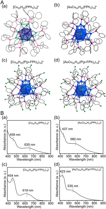 | ||
| Fig. 14 (A) Total structures and (B) UV/Vis spectra of (a) [Cu25H22(PPh3)12]+, (b) [AuCu24H22(PPh3)12]+, (c) [Cu25H22(P(p-FPh)3)12]+ and (d) [AuCu24H22(P(p-FPh)3)12]+. Color labels: gold = Au; blue = Cu; green = F; purple = P; gray = C. All H atoms are omitted for clarity. (A) (a) is reproduced with permission from ref. 274. Copyright 2015 American Chemical Society. (A) (b–d) and (B) are reproduced with permission from ref. 275. Copyright 2019 American Chemical Society. | ||
![[triple bond, length as m-dash]](https://www.rsc.org/images/entities/char_e002.gif) CR and fluoroacetic acid. In 2020, Aikens and Sun et al. synthesized [Cu23(C
CR and fluoroacetic acid. In 2020, Aikens and Sun et al. synthesized [Cu23(C![[triple bond, length as m-dash]](https://www.rsc.org/images/entities/char_e002.gif) CtBu)13(CF3COO)6]0 containing Cu(0) using various reducing agents.276 First, copper(II) trifluoroacetate (Cu(CF3COO)2), Cu powder, and tBuC
CtBu)13(CF3COO)6]0 containing Cu(0) using various reducing agents.276 First, copper(II) trifluoroacetate (Cu(CF3COO)2), Cu powder, and tBuC![[triple bond, length as m-dash]](https://www.rsc.org/images/entities/char_e002.gif) CH were mixed and stirred in dichloromethane and methanol, and when the solution turned pale yellow, Ph2SiH2 was added. After aging, the crystals were filtered and purified at room temperature to give [Cu23(C
CH were mixed and stirred in dichloromethane and methanol, and when the solution turned pale yellow, Ph2SiH2 was added. After aging, the crystals were filtered and purified at room temperature to give [Cu23(C![[triple bond, length as m-dash]](https://www.rsc.org/images/entities/char_e002.gif) CtBu)13(CF3COO)6]0. The Cu NCs consist of a Cu19 outer shell and Cu4 tetrahedral core (Fig. 15A). Furthermore, UV/Vis measurements of the solid using diffuse reflection spectroscopy revealed that the band gap of [Cu23(C
CtBu)13(CF3COO)6]0. The Cu NCs consist of a Cu19 outer shell and Cu4 tetrahedral core (Fig. 15A). Furthermore, UV/Vis measurements of the solid using diffuse reflection spectroscopy revealed that the band gap of [Cu23(C![[triple bond, length as m-dash]](https://www.rsc.org/images/entities/char_e002.gif) CtBu)13(CF3COO)6]0 is approximately 1.45 eV, which is consistent with the value calculated based on DFT calculations.
CtBu)13(CF3COO)6]0 is approximately 1.45 eV, which is consistent with the value calculated based on DFT calculations.
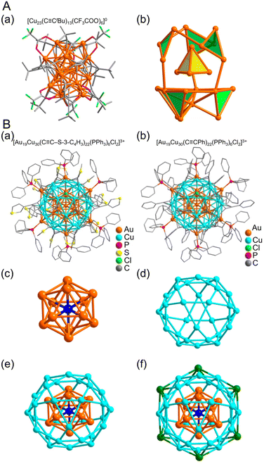 | ||
Fig. 15 (A) (a) Total structure and (b) metal framework of the [Cu23(C![[triple bond, length as m-dash]](https://www.rsc.org/images/entities/char_e002.gif) CtBu)13(CF3COO)6]0. Color labels: Orange, Cu; green, F; gray, C; red, O. (B) Molecular structure of (a) [Au19Cu30(C CtBu)13(CF3COO)6]0. Color labels: Orange, Cu; green, F; gray, C; red, O. (B) Molecular structure of (a) [Au19Cu30(C![[triple bond, length as m-dash]](https://www.rsc.org/images/entities/char_e002.gif) C-3-SC4H3)22(PPh3)6Cl2]3+ and (b) [Au19Cu30(C C-3-SC4H3)22(PPh3)6Cl2]3+ and (b) [Au19Cu30(C![[triple bond, length as m-dash]](https://www.rsc.org/images/entities/char_e002.gif) CPh)22(PPh3)6Cl2]3+. Anatomy of Au19Cu30 kernel structure in Au19Cu30 clusters. (c) Centered icosahedron Au@Au12. (d) Cu30 icosidodecahedron. (e) Au@Au12@Cu30 multi shelled structure. (f) Six outmost Au atoms highlighted in green. (A) is reproduced with permission from ref. 276. Copyright 2020 American Chemical Society. (B) is reproduced with permission from ref. 277. Copyright 2017 American Chemical Society. CPh)22(PPh3)6Cl2]3+. Anatomy of Au19Cu30 kernel structure in Au19Cu30 clusters. (c) Centered icosahedron Au@Au12. (d) Cu30 icosidodecahedron. (e) Au@Au12@Cu30 multi shelled structure. (f) Six outmost Au atoms highlighted in green. (A) is reproduced with permission from ref. 276. Copyright 2020 American Chemical Society. (B) is reproduced with permission from ref. 277. Copyright 2017 American Chemical Society. | ||
Cases of Cu-based alloy NCs protected by C![[triple bond, length as m-dash]](https://www.rsc.org/images/entities/char_e002.gif) CR ligands have also been reported. In 2017, Jiang and Wang et al. reported the synthesis of two types of Au–Cu alloy clusters protected by 3-ethynylthiophene (H3C4S-3-C
CR ligands have also been reported. In 2017, Jiang and Wang et al. reported the synthesis of two types of Au–Cu alloy clusters protected by 3-ethynylthiophene (H3C4S-3-C![[triple bond, length as m-dash]](https://www.rsc.org/images/entities/char_e002.gif) CH) or PhC
CH) or PhC![[triple bond, length as m-dash]](https://www.rsc.org/images/entities/char_e002.gif) CH.277 First, a mixture of the H3C4S-3-C
CH.277 First, a mixture of the H3C4S-3-C![[triple bond, length as m-dash]](https://www.rsc.org/images/entities/char_e002.gif) CAuPPh3 precursor, chloro(triphenylphosphine)gold(I) (PPh3AuCl), and copper(II) nitrate (Cu(NO3)2) was reduced by adding NaBH4. Then, the reaction proceeded in the dark, and the resulting solid was washed to obtain [Au19Cu30(C
CAuPPh3 precursor, chloro(triphenylphosphine)gold(I) (PPh3AuCl), and copper(II) nitrate (Cu(NO3)2) was reduced by adding NaBH4. Then, the reaction proceeded in the dark, and the resulting solid was washed to obtain [Au19Cu30(C![[triple bond, length as m-dash]](https://www.rsc.org/images/entities/char_e002.gif) C-3-SC4H3)22(PPh3)6Cl2]3+. They also synthesized [Au19Cu30(C
C-3-SC4H3)22(PPh3)6Cl2]3+. They also synthesized [Au19Cu30(C![[triple bond, length as m-dash]](https://www.rsc.org/images/entities/char_e002.gif) CPh)22(PPh3)6Cl2]3+ protected with PhC
CPh)22(PPh3)6Cl2]3+ protected with PhC![[triple bond, length as m-dash]](https://www.rsc.org/images/entities/char_e002.gif) C by adding PhC
C by adding PhC![[triple bond, length as m-dash]](https://www.rsc.org/images/entities/char_e002.gif) CAuPPh3 as the Au precursor and CuCl and Cu(NO3)2 as the Cu precursors in the above synthetic scheme. The NCs have identical internal structures (Fig. 15B). At the center is an Au13 core, followed by a Cu30 icosahedral shell, which has a characteristic structure of six Au atoms bonded to this shell portion (Fig. 15B).
CAuPPh3 as the Au precursor and CuCl and Cu(NO3)2 as the Cu precursors in the above synthetic scheme. The NCs have identical internal structures (Fig. 15B). At the center is an Au13 core, followed by a Cu30 icosahedral shell, which has a characteristic structure of six Au atoms bonded to this shell portion (Fig. 15B).
As described above, many synthetic examples of Cu NCs protected by various organic ligands, such as SR, phosphine, and C![[triple bond, length as m-dash]](https://www.rsc.org/images/entities/char_e002.gif) CR, have been reported. These Cu NCs are expected to be applied in electrochemical CRRs, as described in section 3.5.
CR, have been reported. These Cu NCs are expected to be applied in electrochemical CRRs, as described in section 3.5.
3. Electrochemical CO2 reduction reactions of atomically precise metal nanoclusters
3.1 Atomically precise metal nanoclusters as electrocatalysts
As the depletion of fossil resources and the problem of global warming become more serious, there is a growing desire to diversify the industrial sources of energy and reduce greenhouse gases. Electrocatalysts, which induce chemical reactions using electrical energy, have been attracting attention as a means of addressing these problems. Electricity can be produced cleanly using natural energy sources (i.e., without also producing CO2), and electrocatalysts can be used to convert the unused surplus of those sources into chemical energy. Doing so would reduce the loss of electricity in the transmission and storage processes, promoting a cleaner and more sustainable society. Among the various electrocatalytic reactions, in water electrolysis, fuel cells, and electrochemical CO2 reduction are the most widely studied.In recent years, there has been a focus on the development of electrocatalysts that reduce the activation energy of these electrocatalytic reactions and allow them to proceed with less power consumption. In general, an efficient electrocatalyst has many active sites with high reaction rates. The number of active sites is an important factor related to the specific surface area of the catalyst, and the reaction rate is largely related to the adsorption energy of the reacting molecules on the catalyst surface. Chemical reactions at the catalyst surface exhibit the highest activity based on the Sabatier principle, only occurring when the Gibbs energy of adsorption between the catalyst and the reactant is appropriate.278 The reaction cannot occur if there is no adsorption of the reactant on the electrode surface, but if the adsorption is too strong, the reaction cannot proceed. Therefore, depending on the metal species of the electrocatalyst and the adsorption energy of the reactants, the reaction efficiency follows a mountainous trend, called a volcano plot.279
The metal NCs described in section 2 generally have high catalytic activities in a variety of heterogeneous systems based on their large specific surface areas and unique geometric/electronic structures. Recently, many groups have studied the application of metal NCs to electrocatalysts, considering that metal NCs have the potential to outperform conventional materials. Furthermore, the geometric structure of many metal NCs can be revealed by SC-XRD, and the adsorption and reaction processes between the metal NCs as an active site, and reactants can be estimated using theoretical calculations.158,280–287 Therefore, metal NCs have been widely studied as model catalysts to elucidate the reaction mechanisms. If we can clarify the correlation between the electronic/geometric structure of metal NCs and their electrocatalytic activity, we may find new ways to enhance the catalytic activity.
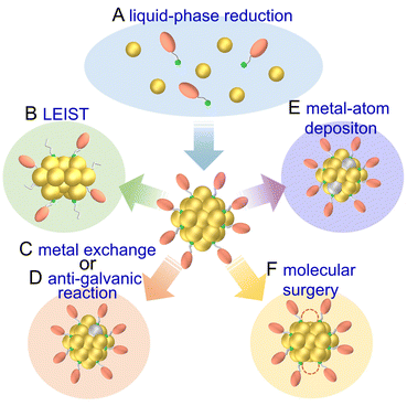
Here, we summarize the application of ligand-protected metal NCs in electrochemical CRRs, with a focus on electrocatalysts using ligand-protected metal NCs obtained by liquid-phase reduction, which can be easily synthesized in large quantities. Particularly, we describe the use of metal NCs that have a well-defined geometric structure.
3.2 Electrocatalytic CO2 reduction reactions using atomically precise metal nanoclusters
Electrochemical CRRs provide a variety of useful reduction products depending on the number of electrons involved in the reaction.279 For example, 2-electron transfer reduction produces CO or HCOOH, 8-electron transfer reduction produces CH4, 16-electron transfer reduction produces ethylene (C2H4), and reduction by more electrons is also possible (eqn (1)–(7)).89,288 First, CO2 is adsorbed on the surface of the metal catalyst and then interacts with the transferred electrons or protons to form an intermediate. Next, these intermediates undergo various reactions and finally desorb from the catalyst surface. There are various theories, but (i) *COOH and (ii) *OCHO are the primary intermediates in most cases. Among these, (i) *COOH is the first intermediate in the formation of CO and various hydrocarbons, and (ii) *OCHO is most likely an intermediate in the formation of HCOOH. (iii) *COCHO, produced by C–C coupling of *CHO and CO, has been reported as an important intermediate in the formation of C2 compounds. Therefore, different metal species also have different binding energies to these intermediates, and these differences change the main products (Fig. 16). For example, using bulk metals as catalysts, (i) CO is obtained as a product for Au or Ag; (ii) HCOOH is obtained for Pb, Sn, and In; and (iii) a variety of organic products, such as aldehydes, alcohols, and C2 compounds, are obtained for Cu. However, certain metals, such as Pt, Ni, and Pd, which are highly active in HER, are less useful catalysts in CRR because the adsorption of *H prevents the formation of carbon products.289,290 Additionally, the specific geometric/electronic structures of metal NCs affect the selectivity. As described in section 2, many metal NCs can be synthesized under atmospheric conditions with atomic accuracy, mainly for group 11 metals (Ag, Au, and Cu). Therefore, most applications of electrochemical CRRs have been based on these metal NCs. In this section, we mainly discuss the relationship between the structure of metal NCs and electrochemical CRR activity in terms of (1) size effects, (2) structure effects, (3) ligand effects, and (4) heterometallic doping effects, with respect to the application of Ag, Au, and Cu NCs in electrochemical CRRs.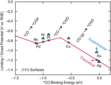 | ||
| Fig. 16 A volcano plot of CO2 reduction reactions for (111) bulk metals. This figure is reproduced with permission from ref. 279. Copyright 2017 AAAS. | ||
3.3 Electrocatalytic CO2 reduction reactions using gold nanoclusters
Many studies of electrochemical CRRs with Au NCs have been reported since 2012 (Tables 1–5). Kauffman et al. reported the first study on electrochemical CRRs using Aun(SR)m. They prepared the catalyst ink by sonicating a solution containing [Au25(PET)18]− (Fig. 2AB) dissolved in acetone, carbon black (CB), Nafion, and methanol. Then, the prepared catalyst ink was loaded on a glassy carbon electrode (GCE) and dried naturally to form the working electrode. Evaluation of the CRR activity showed that the current curves were different after saturation with nitrogen (N2) and CO2 when the potentials were traced to negative. The onset potential for CO formation was found to be −0.193 V vs. RHE, according to the potential-dependent product analysis (Fig. 17A). Compared with the ideal CO2 to CO redox potential (−0.103 V vs. RHE), the overvoltage of bulk Au was 200–300 mV, whereas that of [Au25(PET)18]− was only 90 mV (Fig. 17B). The FE of CO formation (FECO) was approximately 100% at −1.0 V vs. RHE. This was 7–700 times higher than Au NPs with 2–5 nm particle sizes and bulk Au. Furthermore, the FECO for [Au25(PET)18]− was stable at a relatively high selectivity of 80.8–99.6%, compared with 26.9–92.9% for bulk Au and 71.0–96.9% for Au NPs. The turnover frequency of CO (TOFCO) was calculated to be 87 molecules per site per s. In addition, the absorption spectrum of [Au25(PET)18]− was maintained after electrochemical measurements, further indicating its stability.291 The adsorption of CO2 was also predicted using a simplified model of [Au25(SCH3)18]− for the DFT calculation (Fig. 17C). As a result, the binding energy is 0.13 eV in the stable structure, where the oxygen atom of CO2 interacts with the three S atoms located in the shell of Au25 (Fig. 17C). These small perturbations in the internal structure of the molecule were consistent with the physisorption of CO2. CRRs were also investigated using [Au25(PET)18]z (z = −1, 0, and +1).292 [Au25(PET)18]− exhibited higher activity for CO2 reduction to CO than [Au25(PET)18]z (z = 0 and +1). From DFT calculations, they speculated that this is due to the stronger binding energy for CO2 and H+ co-adsorption.| CO2 + e− → CO2*− E = −1.50 V vs. RHE | (1) |
| CO2 + 2H+ + 2e− → CO + H2O E = −0.11 V vs. RHE | (2) |
| CO2 + 2H+ + 2e− → HCOOH E = −0.25 V vs. RHE | (3) |
| CO2 + 4H+ + 4e− → HCHO + H2O E = −0.07 V vs. RHE | (4) |
| CO2 + 6H+ + 6e−→ CH3OH + H2O E = 0.02 V vs. RHE | (5) |
| CO2 + 8H+ + 8e− → CH4+ 2H2O E = 0.17 V vs. RHE | (6) |
| 2CO2 + 12H+ + 12e− → C2H4 + 4H2O E = 0.06 V vs. RHE | (7) |
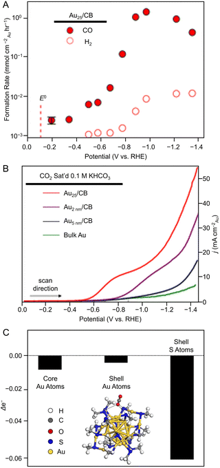 | ||
| Fig. 17 (A) Potential-dependent H2 and CO formation rates for Au25/CB. (B) LSVs of various Au catalysts in quiescent CO2 saturated 0.1 M KHCO3 (pH = 7). (C) DFT model of stable CO2 adsorption where an O atom of CO2 interacts with three S atoms in the shell and Bader charge analysis showing the change in Au25 valence electrons upon CO2 adsorption. Panels (A)–(C) are reproduced with permission from ref. 291. Copyright 2012 American Chemical Society. | ||
| Nanocluster/nanoparticle | Electrolytes | Electrolyzer | Main product | Selectivity (@V vs. RHE) | Current density (mA cm−2 @V vs. RHE) | Stability (@V vs. RHE) | Ref. |
|---|---|---|---|---|---|---|---|
| PET = phenylethanethiolate, PPh3 = triphenylphosphine, TBBT = 4-tert-butylbenzenethiolate, SC6H13 = 1-hexanethiolate, DPPE = 1,2-bis(diphenylphosphino)ethane, DPPP = 1,3-bis(diphenylphosphino)propane.a vs. Ag/AgCl.b Au38Q.c Au38T.d Vulcan XC-72R.e Vulcan XC-72.f Carbon black.g Multi-walled carbon nanotube.h Carbon paper. | |||||||
| [Au25(PET)18]− | 0.1 M KHCO3 aq. | H-cell | CO | ∼100%@−1.0 | N/A | N/A |
291![[thin space (1/6-em)]](https://www.rsc.org/images/entities/char_2009.gif) d d |
| Au 2 nm NPs | 97%@−1.0 | N/A | N/A | ||||
| Au 5 nm NPs | 74%@−1.0 | N/A | N/A | ||||
| Bulk Au NPs | 27%@−1.0 | N/A | N/A | ||||
| [Au25(PET)18]− | 0.1 M KHCO3 aq. | H-cell | CO | 99%@−1.0 | N/A | N/A |
292![[thin space (1/6-em)]](https://www.rsc.org/images/entities/char_2009.gif) d d |
| [Au25(PET)18]0 | 82%@−1.0 | N/A | N/A | ||||
| [Au25(PET)18]+ | 81%@−1.0 | N/A | N/A | ||||
| Au25(SC6H13)18 | 1.0 M KOH aq. or 3.0 M KOH aq. | Flow cell | CO | ∼90%@−0.56 | 59@−0.56 | 100 h@−1.16 |
295![[thin space (1/6-em)]](https://www.rsc.org/images/entities/char_2009.gif) e e |
| Au38(SC6H13)24 | ∼90%@−0.56 | 100@−0.56 | 25 h@−1.16 | ||||
| Au144(SC6H13)60 | ∼92%@−0.56 | 230@−0.56 | 25 h@−1.16 | ||||
| Au137(PET)56 | 0.1 M NBu4PF6 in DMF | 3 neck flask | N/A | N/A | N/A | N/A | 294 |
| Au25(PET)18 | 0.1 M KHCO3 aq. | N/A | CO | ∼90%@−1.0 | N/A | 36 h@−1.0 |
293![[thin space (1/6-em)]](https://www.rsc.org/images/entities/char_2009.gif) f f |
Au38(PET)24![[thin space (1/6-em)]](https://www.rsc.org/images/entities/char_2009.gif) b b |
0.5 M KHCO3 aq. | H-cell | CO | ∼100%@−0.77 | 32@−0.87 | N/A |
296![[thin space (1/6-em)]](https://www.rsc.org/images/entities/char_2009.gif) f f |
Au38(PET)24![[thin space (1/6-em)]](https://www.rsc.org/images/entities/char_2009.gif) c c |
∼100%@−0.77 | 23@−0.87 | N/A | ||||
| Au144(PET)60 | ∼100%@−0.77 | 26@−0.87 | N/A | ||||
| Au333(PET)79 | ∼95%@−0.77 | 23@−0.87 | N/A | ||||
| Au28(TBBT)20 | ∼100%@−0.77 | 28@−0.87 | N/A | ||||
| Au36(TBBT)24 | ∼100%@−0.77 | 26@−0.87 | N/A | ||||
| Au279(TBBT)84 | ∼90%@−0.77 | 18@−0.87 | N/A | ||||
| Au4(PPh3)4I2 | 0.5 M KHCO3 aq. | H-cell | CO | ∼55%@−0.9 | ∼3@−0.9 | N/A |
298![[thin space (1/6-em)]](https://www.rsc.org/images/entities/char_2009.gif) g g |
| H2 | ∼45%@−0.9 | ∼3@−0.9 | N/A | ||||
| Au11(PPh3)7I3 | CO | ∼77%@−0.9 | ∼5@−0.9 | N/A | |||
| H2 | ∼23%@−0.9 | ∼2@−0.9 | N/A | ||||
| [Au6(DPPP)4]2+ | 0.2 M KHCO3 aq. | Flow cell | CO | ∼80%@−1.5a | −3.3@−1.5a | 4 h@−1.5a |
297![[thin space (1/6-em)]](https://www.rsc.org/images/entities/char_2009.gif) h h |
| H2 | ∼15%@−1.5a | N/A | N/A | ||||
| [Au9(PPh3)8]3+ | CO | ∼83%@−1.5a | −3.1@−1.5a | N/A | |||
| H2 | ∼17%@−1.5a | N/A | N/A | ||||
| [Au13(DPPE)5Cl2]3+ | CO | ∼90%@−1.5a | −3.3@−1.5a | N/A | |||
| H2 | ∼15%@−1.5a | N/A | N/A | ||||
| Au101(PPh3)21Cl5 | CO | ∼76%@−1.5a | −6.6@−1.5a | N/A | |||
| H2 | ∼20%@−1.5a | N/A | N/A | ||||
| Nanocluster/nanoparticle | Electrolytes | Electrolyzer | Main product | Selectivity (@V vs. RHE) | Current density (mA cm−2@V vs. RHE) | Stability (@V vs. RHE) | Ref. |
|---|---|---|---|---|---|---|---|
| PET = phenylethanethiolate, PPh3 = triphenylphosphine, TBBT = 4-tert-butylbenzenethiolate.a Au38Q.b Au38T.c Vulcan XC-72R.d Carbon black.e Vulcan XC-72. | |||||||
| [Au25(PET)18]− | 0.5 M KHCO3 aq. | H-cell | CO | 73.5%@−1.07 | N/A | N/A |
299![[thin space (1/6-em)]](https://www.rsc.org/images/entities/char_2009.gif) c c |
| H2 | 24.9%@−1.07 | N/A | N/A | ||||
| [Au25(PPh3)10(PET)5Cl2]2+ | CO | ∼55%@−1.07 | N/A | N/A | |||
| H2 | 41.2%@−1.07 | N/A | N/A | ||||
Au38(PET)24![[thin space (1/6-em)]](https://www.rsc.org/images/entities/char_2009.gif) a a |
0.5 M KHCO3 aq. | H-cell | CO | ∼100%@−0.77 | 32@−0.87 | N/A |
296![[thin space (1/6-em)]](https://www.rsc.org/images/entities/char_2009.gif) d d |
Au38(PET)24![[thin space (1/6-em)]](https://www.rsc.org/images/entities/char_2009.gif) b b |
∼100%@−0.77 | 23@−0.87 | N/A | ||||
| Au44(TBBT)24 | 0.5 M KHCO3 aq. | H-cell | CO | 83%@−0.57 | 1.9@−0.57 | N/A |
300![[thin space (1/6-em)]](https://www.rsc.org/images/entities/char_2009.gif) e e |
| H2 | ∼17%@−0.57 | N/A | |||||
| Au44(PPh3)(TBBT)26 | CO | 97%@−0.57 | 3.8@−0.57 | 60 h@−0.57 | |||
| H2 | 2.7%@−0.57 | N/A | |||||
| Au44(PPh3)2(TBBT)24 | CO | 90%@−0.57 | 3.1@−0.57 | N/A | |||
| H2 | ∼10%@−0.57 | N/A | |||||
| Nanocluster/nanoparticle | Electrolytes | Electrolyzer | Main product | Selectivity (@V vs. RHE) | Current density (mA cm−2@V vs. RHE) | Stability (@V vs. RHE) | Ref. |
|---|---|---|---|---|---|---|---|
| PET = phenylethanethiolate, PPh3 = triphenylphosphine, SNap = 1-naphthalenethiolate, SePh = phenylselenolate, NHCMe = 1,3-dihydro-1,3-dimethyl-2H-benzimidazol-2-ylidene, NHCiPr = 1,3-dihydro-1,3-diisopropyl-2H-benzimidazol-2-ylidene, Ph-form = N,N′-diphenylformamidinate, PVP = polyvinylpyrrolidone, p-MBT = 4-methylbenzenethiolate, NHCBn = 1,3-dibenzyl-1H-benzo[d]imidazol-2-ylidene, DPPE = 1,2-bis(diphenylphosphino)ethane, MEA = membrane electrode assembly.a vs. MEA-cell potential.b The ligand-removed Au25(PET)18 by electrochemical pretreatment.c The ligand-removed Au25(PET)18 by thermal pretreatment.d Multi-walled carbon nanotube.e Carbon paper.f Ketjen black (EC300J).g Carbon gas diffusion layer (TGP-H-060).h Vulcan XC-72R.i Sulfur-doped graphene.j Carbon. | |||||||
| [Au7(PPh3)7H5]2+ | 0.5 M KHCO3 aq. | H-cell | H2 | 10%@−0.67 | ∼6@−0.97 | 5 h@−0.77 |
232![[thin space (1/6-em)]](https://www.rsc.org/images/entities/char_2009.gif) d d |
| CO | ∼90%@−0.67 | ∼0@−0.97 | |||||
| [Au8(PPh3)7]2+ | H2 | ∼26%@−0.67 | ∼1@−0.97 | 5 h@−0.77 | |||
| CO | 73.5%@−0.77 | 6.47@−0.97 | |||||
| [Au11(PPh3)7(NHCMe)Cl2]+ | 0.1 M KHCO3 aq. | H-cell | CO | 80%@−1.0 | N/A | N/A |
238![[thin space (1/6-em)]](https://www.rsc.org/images/entities/char_2009.gif) e e |
| [Au11(PPh3)8Cl2]+ | 80%@−1.0 | N/A | N/A | ||||
| [Au11(PPh3)7(NHCiPr)Cl2]+ | ∼30%@−1.0 | N/A | N/A | ||||
| [Au11(DPPE)5]3+ | 0.5 M KHCO3 aq. | H-cell | CO | 70.6%@−0.6 | 1.5@−0.6 | N/A |
231![[thin space (1/6-em)]](https://www.rsc.org/images/entities/char_2009.gif) f f |
| [Au22H3(DPPE)3(PPh3)8]3+ | 92.7%@−0.6 | 3.5@−0.6 | 10 h@−0.6 | ||||
| [Au24(NHCBn)14Cl2H3]3+ | 0.1 M KHCO3 aq. | MEA-cell | CO | N/A | 10@2.4a | 100 h@3.2a,b |
249![[thin space (1/6-em)]](https://www.rsc.org/images/entities/char_2009.gif) g g |
| [Au13(NHCBn)9Cl3]2+ | N/A | 10@2.5a | N/A | ||||
| Ag NPs | N/A | 10@2.8a | N/A | ||||
| [Au25(PET)18]− | 0.5 M KHCO3 aq. | H-cell | CO | ∼100%@−0.8 | 22@−0.8 | N/A |
301![[thin space (1/6-em)]](https://www.rsc.org/images/entities/char_2009.gif) h h |
| [Au25(SNap)18]− | ∼95%@−0.8 | 20@−0.8 | |||||
| [Au25(SePh)18]− | ∼80%@−0.8 | 15@−0.8 | |||||
| Au25(PET)18 (Electrochemical)b | 0.1 M KHCO3 aq. | H-cell | CO | 82%@−0.59 | N/A | 3 h@−0.5 |
305![[thin space (1/6-em)]](https://www.rsc.org/images/entities/char_2009.gif) i i |
| Au25(PET)18(Thermal)c | 64%@−0.59 | 3 h@−0.5 | |||||
| [Au28(C2B10H11S)12(THT)4]4+ | 0.5 M KHCO3 aq. | H-cell | CO | 98.5%@−0.9 | ∼8@−0.9 | 5.5 h @−0.9 |
303![[thin space (1/6-em)]](https://www.rsc.org/images/entities/char_2009.gif) h h |
| [Au28(C4B10H11)12(THT)8]3+ | ∼70%@−0.9 | ∼4@−0.9 | 5.5 h @−0.9 | ||||
| [Au28(Ph-form)12]2+ | 0.5 M KHCO3 aq. | H-cell | CO | 96.5%@−0.57 | N/A | 40 h@−0.69 |
250![[thin space (1/6-em)]](https://www.rsc.org/images/entities/char_2009.gif) d d |
| PVP-coated Au NPs | ∼25%@−0.57 | N/A | N/A | ||||
| [Au55(p-MBT)24(PPh3)6]3+ | 0.1 M KHCO3 aq. | H-cell | CO | 94.1%@−0.6 | ∼410@−0.9 | 4 h@−0.6 |
233![[thin space (1/6-em)]](https://www.rsc.org/images/entities/char_2009.gif) j j |
| [Au25(p-MBT)5(PPh3)10Cl2]2+ | 75.1%@−0.6 | N/A | N/A | ||||
| Nanocluster/nanoparticle | Electrolytes | Electrolyzer | Main product | Selectivity (@V vs. RHE) | Partial current density (mA cm−2@V vs. RHE) | Stability (@V vs. RHE) | Ref. |
|---|---|---|---|---|---|---|---|
| PET = phenylethanethiolate, TBBT = 4-tert-butylbenzenethiolate, SC6H11 = cyclohexanethiolate, SC6H13 = 1-hexanethiolate, S-tol = p-toluenethiolate, d-MBT = 3,5-dimethylbenzenethiolate, SCH2PhtBu = 4-tert-butylbenzylthiolate, SPhMe2 = 2,4-dimethylbenzenethiolate.a vs. cell potential.b Vulcan XC-72R.c Carbon paper.d Carbon paper (Toray TGP-H090). | |||||||
| [Au19Cd2(SC6H11)16]− | 0.5 M KHCO3 aq. | H-cell | CO | ∼95%@∼−0.67 | 42@−0.9 | N/A |
308![[thin space (1/6-em)]](https://www.rsc.org/images/entities/char_2009.gif) b b |
| [Au23(SC6H11)16]− | ∼65%@∼−0.67 | 18@−0.9 | N/A | ||||
| Au25(PET)18 | 1.0 M KHCO3 aq. | H-cell | CO | ∼80%@−0.4 | 8@−0.8 | 25 h@−0.7 |
188![[thin space (1/6-em)]](https://www.rsc.org/images/entities/char_2009.gif) c c |
| HCOOH | ∼10%@−0.4 | ||||||
| Au24Cd(PET)18 | CO | ∼90%@−0.4 | 35@−0.8 | 25 h@−0.7 | |||
| HCOOH | ∼8%@−0.4 | ||||||
| Au19Cd3(S-tol)18 | CO | ∼60%@−0.4 | 5@−0.8 | 25 h@−0.7 | |||
| HCOOH | 0%@−0.4 | ||||||
| Au38Cd4(d-MBT)30 | CO | ∼60%@−0.4 | 12@−0.8 | 25 h@−0.7 | |||
| HCOOH | ∼10%@−0.4 | ||||||
| Au47Cd2(TBBT)31 | 0.5 M KHCO3 aq. | H-cell | CO | 96%@−0.57 | 3.2@−0.57 | 20 h@−0.57 |
306![[thin space (1/6-em)]](https://www.rsc.org/images/entities/char_2009.gif) b b |
| Au44(TBBT)28 | 83%@−0.57 | 1.6@−0.57 | 20 h@−0.57 | ||||
| 1.5 nm Au NPs | 76%@−0.67 | 1.0@−0.57 | 20 h@−0.67 | ||||
| Au25(SC6H13)18 | 0.1 M KHCO3 aq. + 0.4 M KCl | H-cell | H2 | ∼6%@−0.5 | 12@−1.0 | N/A |
309![[thin space (1/6-em)]](https://www.rsc.org/images/entities/char_2009.gif) b b |
| CO | ∼90%@−0.5 | ||||||
| PtAu24(SC6H13)18 | H2 | ∼80%@−0.5 | 20@−1.0 | N/A | |||
| CO | ∼20%@−0.5 | ||||||
| Au38(SCH2PhtBu)24 | 0.5 M KHCO3 aq. | H-cell | CO | ∼70%@−0.6 | 7.5@−0.9 | N/A |
199![[thin space (1/6-em)]](https://www.rsc.org/images/entities/char_2009.gif) d d |
| PtAu37(SCH2PhtBu)24 | ∼80%@−0.6 | 7.5@−0.9 | N/A | ||||
| Pt2Au36(SCH2PhtBu)24 | ∼60%@−0.6 | 14@−0.9 | N/A | ||||
Ag4+xAu40−x(C![[triple bond, length as m-dash]](https://www.rsc.org/images/entities/char_e002.gif) CPh(CH3)2)28 CPh(CH3)2)28 |
0.5 M KHCO3 aq. | H-cell | CO | ∼98%@−0.5 | 18@−0.8 | 10 h@−0.6 |
310![[thin space (1/6-em)]](https://www.rsc.org/images/entities/char_2009.gif) d d |
Au44(C![[triple bond, length as m-dash]](https://www.rsc.org/images/entities/char_e002.gif) CPh(CH3)2)28 CPh(CH3)2)28 |
∼75%@−0.5 | 6@−0.8 | 10 h@−0.6 | ||||
| Au44(d-MBT)28 | ∼80%@−0.5 | 8@−0.8 | 10 h@−0.6 | ||||
| [Au25(PET)18]− | 1.0 M KOH aq. | Flow cell or zero-gap cell | CO | ∼100%@−0.2 | ∼40@−0.2 | N/A | 190 |
| [Ag25(SPhMe2)18]− | ∼95%@−0.6 | ∼50@−0.6 | N/A | ||||
| [AuAg12@Au12(PET)18]− | ∼90%@−0.2 | ∼30@−0.2 | 24 h@−0.5a | ||||
| [Au4Pd6(TBBT)12]− | 0.5 M KHCO3 aq. | H-cell | CO | 88.1%@−0.57 | ∼11@−0.9 | 65 h@−0.57 |
202![[thin space (1/6-em)]](https://www.rsc.org/images/entities/char_2009.gif) b b |
| [Au3AgPd6(TBBT)12]− | 94.1%@−0.57 | ∼15@−0.9 | 65 h@−0.57 | ||||
| [Au24Pd(PET)18]0 | 0.1 M KHCO3 aq. | H-cell | CO | ∼100%@−1.1 | 35@−1.25 | 6 h@−0.8 |
311![[thin space (1/6-em)]](https://www.rsc.org/images/entities/char_2009.gif) b b |
| [Au25(PET)18]0 | ∼70%@−1.1 | 20.3@−1.1 | N/A | ||||
| Nanocluster/nanoparticle | Electrolytes | Electrolyzer | Main product | Selectivity (@V vs. RHE) | Current density (mA cm−2@V vs. RHE) | Stability (@V vs. RHE) | Ref. |
|---|---|---|---|---|---|---|---|
| PET = phenylethanethiolate, PVDF = poly vinylidene fluoride.a Vulcan XC-72R. | |||||||
| [Au25(PET)18]−/Nafion | 0.1 M KHCO3 aq. | Two compartment cells | CO | ∼90%@−0.8 | N/A | N/A |
312![[thin space (1/6-em)]](https://www.rsc.org/images/entities/char_2009.gif) a a |
| [Au25(PET)18]−/PVDF | ∼55%@−0.8 | ||||||
| Au foil | ∼4.6%@−0.8 | ||||||
| [Au25(SC6H13)18]− | KOH aq. (1–5 M) or 0.5 M PBS + 0.5 M KCl aq. (pH 8–13) | Flow cell | CO | ∼95%@−0.4 | ∼100@−0.4 | 12 h@−1.16 |
313![[thin space (1/6-em)]](https://www.rsc.org/images/entities/char_2009.gif) a a |
Next, the researchers investigated practical applications.293 Specifically, they evaluated the relationship between the amount of [Au25(PET)18]− loaded per electrode area (using CB as the support) and their resulting particle size, which was determined by transmission electron microscopy (TEM) (Fig. 18A). As a result, the size of [Au25(PET)18]− was 1.4 ± 0.4 nm when the loading amount was 0.96 μgAu cmgeo−2, indicating that the initial particle size was approximately maintained. However, aggregates were observed when loading was increased to 15 μgAu cmgeo−2. With an [Au25(PET)18]− loading of 0.96 μgAu cmgeo−2, CO2 flow rate of 50 mL min−1, and applied potential of −1.0 V vs. RHE, electrolytic CO2 reduction for 1 h produced 810 ± 11 L gAu−1 h−1 of CO (FECO > 90%). Even after 36 h of continuous CO2 reduction by electrolysis, CO production of 7450 ± 59 L gAu−1 h−1 and an FECO of approximately 86% was maintained (Fig. 18B). In addition, 1–4 × 10⁶ molCO2 molcatalyst−1 of turnover (TON) was obtained after 12 h of CO2 reduction by electrolysis in combination with a 1.5 W, 6 V solar cell or a 6 V solar rechargeable battery.
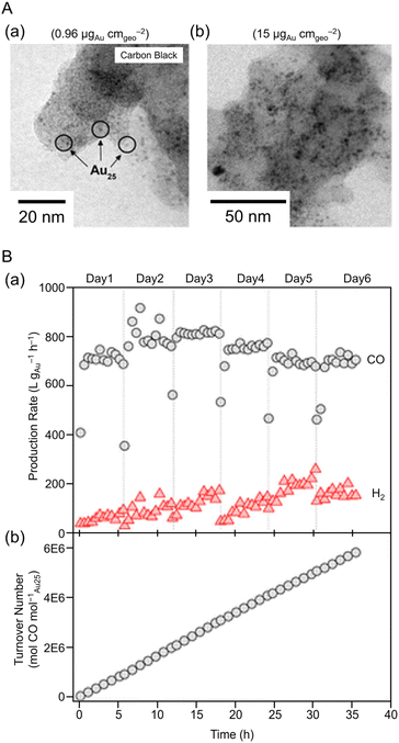 | ||
| Fig. 18 (A) TEM images of carbon-supported Au25 at low and high loadings. Isolated 1.4 ± 0.4 nm Au NC were observed on the carbon black support at low loadings. (B) Day-to-day (a) product formation rates, (b) cumulative TON (mol of CO/(mol of Au25)). Panels (A) and (B) are reproduced with permission from ref. 293. Copyright 2015 American Chemical Society. | ||
In 2021, Lee and Yoo et al. evaluated CRR activity using three different core sizes of Aun(SR)m (i.e., [Au25(SC6H13)18]−, [Au38(SC6H13)24]0 and [Au144(SC6H13)60]0).295 As a result, CRR activity increased with decreasing Aun(SR)m size, showing much higher CO production current density (jCO) and selectivity (FECO > 90%) than Au NPs (25 ± 4 nm particle size). Electrochemical measurements, X-ray photoelectron spectroscopy (XPS), and DFT calculations indicated that the application of applied potential in Aun(SR)m (n = 25, 38, 144) leads to a progressive de-thiolation and the appearance of an active Au site, which is converted to a more active and stable geometry. Furthermore, it was suggested that Au sites de-thiolated at the staple motif promote CRRs by stabilizing the *COOH intermediate.
In 2022, Kauffman, Mpourmpakis, and Jin et al. used two different Aun(SR)m with a series of sizes ([Au38(PET)24]0, [Au144(PET)60]0, Au333(PET)79, [Au28(TBBT)20]0, [Au36(TBBT)24]0, and Au279(TBBT)84) to evaluate CRR activity.296 A catalyst ink of each Aun(SR)m loaded at 10 wt% in isopropyl alcohol and 0.2 wt% Nafion on CB was placed on GCE, and CRR measurements were performed in 0.5 M potassium hydrogen carbonate (KHCO3) aq. As a result, only CO and H2 were produced, and the PET-protected Aun(SR)m ([Au38(PET)24]0 and [Au144(PET)60]0) and TBBT-protected Aun(SR)m ([Au28(TBBT)20]0 and [Au36(TBBT)24]0) showed almost 100% FECO at potentials more positive than −0.8 V vs. RHE and −0.77 V vs. RHE, respectively (Fig. 19A). Furthermore, Au333(PET)79 and Au279(TBBT)84 with larger core sizes showed lower FECO and jco values than Aun(SR)m with smaller core sizes (Fig. 19A). This size dependence may have been observed because the S atom of the ligand is the CRR active site and the ratio of S atoms to Au atoms (RS/Au) is larger for Aun(SR)m with a smaller core size (Fig. 19B). The authors also attribute the higher activity of PET-protected Aun(SR)m to the difference in ligand conductivity and ligand removal energies compared with TBBT-protected Aun(SR)m.
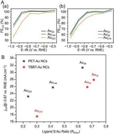 | ||
Fig. 19 (A) FECO of (a) PET-protected Au38, Au144 and Au333 and (b) TBBT-protected Au28, Au36 and Au279 NCs. (B) Electrochemical performance: jCO (at −0.87 V vs. RHE) vs. S![[thin space (1/6-em)]](https://www.rsc.org/images/entities/char_2009.gif) : :![[thin space (1/6-em)]](https://www.rsc.org/images/entities/char_2009.gif) Au ratio of Au38, Au144, Au333 and Au28, Au36, Au279 series of NCs (A) and (B) are reproduced with permission from ref. 296. Copyright 2022 Wiley-VCH GmbH. Au ratio of Au38, Au144, Au333 and Au28, Au36, Au279 series of NCs (A) and (B) are reproduced with permission from ref. 296. Copyright 2022 Wiley-VCH GmbH. | ||
In 2023, Sharma, Golovko, and Marshall et al. also reported on the size dependence in CRRs using phosphine-protected Au NCs.297 The CRR activities of [Au6(DPPP)4](NO3)2, [Au9(PPh3)8](NO3)3, [Au13(DPPE)5Cl2]Cl3, and [Au101(PPh3)21]Cl5 were measured and showed high selectivity for CO formation (FECO = 75–90%), and [Au13(DPPE)5Cl2]Cl3 showed slightly higher CO selectivity compared with other NCs. Additionally, the calcination process for ligand removal was found to cause aggregation of the Au NCs, thus decreasing the CO selectivity. It was also reported that Au4 clusters (Au4(PPh3)4I2) stabilized by phosphine and iodide (I) show higher CO selectivity (FECO = >60%) than Au11(PPh3)7I3 (FECO = <60%).298
From these reports, the size reduction of Au NCs contributes to the improvement of CRR activity and selectivity. This is probably due to the increase in active sites to increase in specific surface area and the change in the electronic state of metal NCs, which is advantageous for CO2 adsorption.
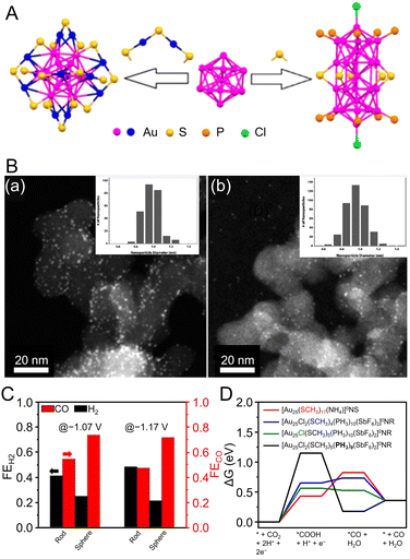 | ||
| Fig. 20 (A) Atom packing structures of Au25 nanosphere ([Au25(PET)18]−) and nanorod ([Au25(PPh3)10(PET)5Cl2]2+). (B) STEM images and particle size histograms of (a) Au25 nanosphere and (b) nanorod supported on carbon black. (C) FECO and FEH2 at the potential of −1.07 and −1.17 V over Au25 nanosphere and nanorod, respectively. (D) Free energy diagrams (ΔG) for CO2 reduction to CO on the ligand-removed NCs at 0 V vs. RHE. The black, blue, green, and red lines represent CO2 reduction to CO on the nanorod with PH3 removed, the nanorod with –SCH3 removed, the nanorod with –Cl removed, and on the nanosphere with –SCH3 removed, respectively. Panels (A)–(D) are reproduced with permission from ref. 299. Copyright 2018 American Chemical Society. | ||
In 2022, Kauffman, Mpourmpakis, and Jin et al. evaluated CRR activity using two structural isomers of Au38(PET)24 (Fig. 4A; Au38Q and Au38T).296 Au38Q exhibited an FECO of 87% at −0.97 V vs. RHE, and Au38T exhibited a lower FECO than Au38Q, especially at more negative potentials (67% at −0.97 V vs. RHE). Thus, they investigated the differences in these activities based on DFT calculations. As a result, the average thermodynamic barrier to ligand removal (exposed active site) was similar for the two Au38(PET)24. However, there are significant differences in the average *COOH formation energies, indicating a linear trend between the *COOH formation energy and the ligand removal energy. Specifically, the average *COOH production energy at the two S sites for Au38Q is 0.17 eV, compared with 0.31 eV for Au38T. This indicates that the differences in CRR activity between the two isomers may be due to differences in the ease of *COOH formation. Overall, two Au38(PET)24 with the same size, composition, and number of ligands can have substantially different catalytic selectivity and activities if their underlying structures are different, which can affect the formation energies.
Asymmetric structural defects of metal NCs can induce enhanced activity. Using Au44(PPh3)(TBBT)26 and Au44(PPh3)2(TBBT)24 with fcc metal cores co-protected by PPh3 and TBBT, and Au44(TBBT)28, changes in CRR activity due to ligand defects have also been reported. Au44(PPh3)(TBBT)26 with a single Au atom at the bottom of the fcc lattice exhibited high CO selectivity. DFT calculations showed that this active site promotes the electrochemical reduction of CO2 to CO by lowering the free energy of *COOH formation.300
From this report, even in Au NCs composed of the same chemical composition, the adsorption energy with the CRR intermediate changes due to the difference in the geometric structure, and Au NCs with different geometries showed different CRR activities.
In 2022, Wang, Zang, and Mak et al. studied the effect of the protective ligand on the CRR activity using [Au28(C2B10H11S)12(THT)4Cl4]0 (THT = tetrahydrothiophe) (Au28–S) and [Au28(C4B10H11)12(THT)8]3+ (Au28–C),302 which have the same metal core but different ligand shells.303 As shown in Fig. 21A, Au28–S and Au28–C have almost the same Au core structure, but the ligand group of the carborane ligand changes from a C![[triple bond, length as m-dash]](https://www.rsc.org/images/entities/char_e002.gif) CR group (σ–π donor) to an SR group (σ donor), and the four THT ligands in Au28–C are replaced by four Cl ions in Au28–S. As a result, the total numbers of valence electrons in Au28–C and Au28–S are 12e− and 13e−, respectively. As shown in Fig. 21B, Au28–S exhibited higher CRR catalytic activity than Au28–C. Au28–S exhibited a maximum FECO of 98.5% at −0.9 V vs. RHE, approximately 1.4 times that of Au28–C. Furthermore, time-resolved in situ Fourier transform infrared (FT-IR) spectroscopy showed that the vibrational peak V(C–O) at 1362 cm−1 and the C
CR group (σ–π donor) to an SR group (σ donor), and the four THT ligands in Au28–C are replaced by four Cl ions in Au28–S. As a result, the total numbers of valence electrons in Au28–C and Au28–S are 12e− and 13e−, respectively. As shown in Fig. 21B, Au28–S exhibited higher CRR catalytic activity than Au28–C. Au28–S exhibited a maximum FECO of 98.5% at −0.9 V vs. RHE, approximately 1.4 times that of Au28–C. Furthermore, time-resolved in situ Fourier transform infrared (FT-IR) spectroscopy showed that the vibrational peak V(C–O) at 1362 cm−1 and the C![[double bond, length as m-dash]](https://www.rsc.org/images/entities/char_e001.gif) O stretch at 1636 cm−1 of the *COOH intermediate in Au28–S is stronger than that of Au28–C, confirming that Au28–S exhibits higher electrocatalytic activity. In addition, they used DFT calculations to determine the active sites. The Au atom in the linear C2B10H11C
O stretch at 1636 cm−1 of the *COOH intermediate in Au28–S is stronger than that of Au28–C, confirming that Au28–S exhibits higher electrocatalytic activity. In addition, they used DFT calculations to determine the active sites. The Au atom in the linear C2B10H11C![[triple bond, length as m-dash]](https://www.rsc.org/images/entities/char_e002.gif) C–Au–C
C–Au–C![[triple bond, length as m-dash]](https://www.rsc.org/images/entities/char_e002.gif) CC2B10H11 staple of Au28–C has enough space between the two C
CC2B10H11 staple of Au28–C has enough space between the two C![[triple bond, length as m-dash]](https://www.rsc.org/images/entities/char_e002.gif) CR groups to access the CO2 molecule, but in Au28–S, the Cl atom of the surface ligand is removed, and the CO2 molecule is not accessible until the Au atom is exposed. The Gibbs free energy calculations of the CRRs for Au28–S and Au28–C and the time-resolved in situ FT-IR results indicate that the pathway of CO2 reduction to CO is CO2(g) → *CO2− → *COOH → *CO → CO(g), with the rate-limiting step being *COOH formation. Notably, Au28–S is energetically more favorable for CO formation than Au28–C.
CR groups to access the CO2 molecule, but in Au28–S, the Cl atom of the surface ligand is removed, and the CO2 molecule is not accessible until the Au atom is exposed. The Gibbs free energy calculations of the CRRs for Au28–S and Au28–C and the time-resolved in situ FT-IR results indicate that the pathway of CO2 reduction to CO is CO2(g) → *CO2− → *COOH → *CO → CO(g), with the rate-limiting step being *COOH formation. Notably, Au28–S is energetically more favorable for CO formation than Au28–C.
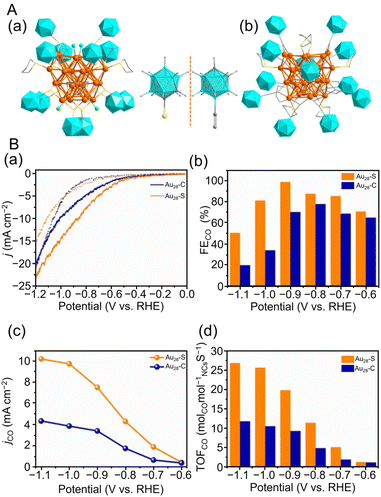 | ||
| Fig. 21 (A) The total crystal structures of (a) Au28–S and (b) Au28–C. (B) (a) Linear sweep voltammetry (LSV) curves of Au28–S and Au28–C in a N2-saturated (dotted line) and a CO2-saturated (full line) 0.5 M KHCO3 solution. (b) FECO at various applied potentials over two NCs. (c) The jCO and (d) TOFCO at the potential of −0.6 to −1.1 V vs. RHE of two NCs. Color codes: orange, green and blue = gold turquoise icosahedrons = carborane; yellow = sulfur; gray = carbon; bright green = chloride. Hydrogen atoms are omitted for clarity. (A) and (B) are reproduced with permission from ref. 303. Copyright 2022 Wiley-VCH GmbH. | ||
Häkkinen, Tsukuda, and Crudden et al. reported on the electrocatalytic activity for CO2 reduction using NHC-coordinated Au11 clusters.238 Specifically, [Au11(PPh3)7(NHCMe)Cl2]Cl (NHCMe = 1,3-dihydro-1,3-dimethyl-2H-benzimidazol-2-ylidene) showed higher stability and CRR mass activity than [Au11(PPh3)8Cl2]Cl. The activity was greatly enhanced when the PPh3 ligand was removed by heating the catalyst at 180 °C for 2 h during catalyst preparation. In 2022, Häkkinen, Tsukuda, and Crudden et al. also reported on the electrocatalytic activity of CRRs with NHC-protected Au24 clusters.249Fig. 22A shows the ESI-MS spectrum of [Au24(NHCBn)14Cl2H3][TFA]3 (TFA = trifluoroacetate; NHCBn = 1,3-dibenzyl-1H-benzo[d]imidazol-2-ylidene) and its geometric structure. [Au24(NHCBn)14Cl2H3]3+ exhibited a high FECO of >90% in the current density range of 10 to 50 mA cm−2 and higher CO selectivity than commercial Ag NP catalysts and [Au13(NHCBn)9Cl3]2+ NCs304 (Fig. 22B). The CRR evaluation at a steady current density of 100 mA cm−2 showed that the FECO and full cell voltage remained stable at approximately 90% and 3.2 V, respectively, even after 100 h, demonstrating the high stability of [Au24(NHCBn)14Cl2H3]3+ (Fig. 22C).
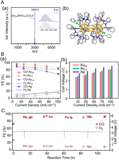 | ||
| Fig. 22 (A) (a) ESI-MS spectra and (b) molecular structure of [Au24(NHCBn)14Cl2H3][TFA]3 as determined by SC-XRD with hydrogen atoms and TFA anions omitted for clarity. (B) (a) FECO and FEH2 at different current densities. (b) Cell voltage vs. current density. (C) Stability of FECO and FEH2, and cell voltage vs. time at an operating current density of 100 mA cm−2 with the Au24 catalyst. Color codes: yellow = gold; green = chloride; grey = carbon; and blue = nitrogen. (A)–(C) are reproduced with permission from ref. 249. Copyright 2022 American Chemical Society. | ||
In 2021, Wang et al. synthesized the first all-amidinate-protected Au NC, [Au28(Ph-form)12]2+, and evaluated its CRR activity.250 The crystal structure of [Au28(Ph-form)12]2+ has a core–shell Au28 kernel consisting of a tetrahedral Au4 core and a twisted truncated tetrahedral Au24 shell (Fig. 8C). Unlike Au NCs protected by SR and C![[triple bond, length as m-dash]](https://www.rsc.org/images/entities/char_e002.gif) CR, [Au28(Ph-form)12]2+ does not have a staple. After loading [Au28(Ph-form)12]2+ at 10 wt% on multiwalled carbon nanotubes (CNTs), the CRR activity was evaluated, and the highest FECO was 96.5% at −0.57 V vs. RHE. These values were higher than those observed for Ph-form Au/CNT and polyvinylpyrrolidone (PVP)-coated Au NPs. In addition, stable potentials at approximately −0.69 V vs. RHE and an FECO of >90% were maintained for 40 h in the long-term activity evaluation at −3.5 mA cm−2. The high stability is attributed to the strong bonding between Au and amidinate ligands, indicating that Au NCs protected by N-containing ligands, such as NHCs and amidinates, can be used as highly stable and active CRR catalysts.
CR, [Au28(Ph-form)12]2+ does not have a staple. After loading [Au28(Ph-form)12]2+ at 10 wt% on multiwalled carbon nanotubes (CNTs), the CRR activity was evaluated, and the highest FECO was 96.5% at −0.57 V vs. RHE. These values were higher than those observed for Ph-form Au/CNT and polyvinylpyrrolidone (PVP)-coated Au NPs. In addition, stable potentials at approximately −0.69 V vs. RHE and an FECO of >90% were maintained for 40 h in the long-term activity evaluation at −3.5 mA cm−2. The high stability is attributed to the strong bonding between Au and amidinate ligands, indicating that Au NCs protected by N-containing ligands, such as NHCs and amidinates, can be used as highly stable and active CRR catalysts.
In 2021, Wang et al. synthesized [Au55(p-MBT)24(PPh3)6]3+, which is co-protected with SR and phosphine and has the fcc structure, and evaluated its CRR activity.233 As a result, [Au55(p-MBT)24(PPh3)6]3+ showed the highest FECO of 94.1% at −0.6 V vs. RHE. The Au55 core in [Au55(p-MBT)24(PPh3)6]3+ is fcc aligned and consists of four layers stacked in ABCA order along the [111] direction. Moreover, [Au55(p-MBT)24(PPh3)6]3+ may have shown higher CRR activity than the Au NPs with an fcc structure because of the protection of the HER-active corner by the p-MBT, which is a hydrophobic ligand. Thus, CRR activity may be controlled by the appropriate selection of surface ligands.
In 2022, Wang et al. investigated the effect of uncoordinated metal sites in CRRs using [Au11(DPPE)5]3+ and a hydride-coordinated Au NC ([Au22H3(DPPE)3(PPh3)8]3+).231 They presume that [Au11(DPPE)5]3+ is completely capped with a diphosphine ligand, whereas [Au22H3(DPPE)3(PPh3)8]3+ has three H atoms bridging six uncoordinated Au sites, and the remaining 14 surface Au atoms are protected with PPh3 ligands. They evaluated the CRR activities and found that compared with [Au11(DPPE)5]3+, [Au22H3(DPPE)3(PPh3)8]3+ exhibited higher FECO (92.7% at −0.6 V vs. RHE), TOFCO (488 h−1), and mass activity (134 A gAu−1). Furthermore, [Au22H3(DPPE)3(PPh3)8]3+ was found to have high stability, with little change in jCO and FECO after more than 10 h of reaction at −0.6 V vs. RHE. The results of DFT calculations suggest that the hydride-coordinated Au atoms in [Au22H3(DPPE)3(PPh3)8]3+ are the active sites, and the bridge H atoms directly hydrogenate CO2 to adsorbed *COOH. Moreover, it was estimated that the H voids are easily recovered by proton reduction, thus completing the catalytic cycle. These findings suggest that Au–H bonds can improve the stability and CRR catalytic activity of Au NCs.
Pei and Wang et al. evaluated the CRR activity for [Au7(PPh3)7H5]2+ with hydride ligands and [Au8(PPh3)7]2+ synthesized by degrading [Au7(PPh3)7H5]2+ using light (300–450 nm) irradiation.232 As a result, [Au7(PPh3)7H5]2+ showed high selectivity for HER (max FEH2 = 98.2% at −0.67 V vs. RHE; FEH2 = FE of H2 generation), whereas [Au8(PPh3)7]2+ was highly selective for CRR (FECO = 73.5% at −0.77 V vs. RHE). UV/Vis and ESI-MS measurements of [Au7(PPh3)7H5]2+ and [Au8(PPh3)7]2+ before and after CRRs did not change significantly, indicating their stability. In addition, isotope labeling experiments with deuterium indicated that all the constituent hydrogen atoms of H2 released during the CO2 reduction process came from the aqueous solution (H3O+) and not from hydrides in the NC. Notably, [Au22H3(DPPE)3(PPh3)]3+,231 protected by hydride ligands, showed high CO selectivity, unlike [Au7(PPh3)7H5]2+, indicating that the reactions between these NCs proceeded via different mechanisms. Therefore, assuming that all the hydrogen atoms come from the aqueous solution and not from the hydride ligands, DFT calculations showed that the values of ΔG of the *COOH formation for [Au7(PPh3)7H5]2+ and [Au8(PPh3)7]2+ are 1.68 and 0.58 eV, respectively. The small potential barrier to COOH* formation might be responsible for the high CO selectivity of [Au8(PPh3)7]2+.
In 2021, Yang et al. investigated the process of ligand removal by thermal and electrochemical treatment of Au25(PET)18 and its effect on the electrolytic reduction of CO2 to CO.305 Under-potential deposition (UPD) measurements of Cu, Au L3 edge X-ray absorption fine structure (EXAFS) spectroscopy, and XPS measurements were used to determine the extent of ligand removal. Increasing the annealing temperature during the thermal treatment and the bias voltage in the electrochemical treatment increased the surface area on the catalyst, indicating that the Au–S bonds were broken, and the surface Au atoms became metallic. In particular, when the reducing potential was applied by electrochemical treatment, there was no change in the Au–S bond strength measured by Cu UPD and FT-EXAFS measurements up to −0.30 V vs. RHE, but from −0.35 V vs. RHE ligand, removal was observed, and the aggregation of Au25(PET)18 was observed in the TEM images after applying a higher reducing potential. For the electrochemical evaluation of CRR activity, S-doped graphene (S–G)-loaded Au25(PET)18 (Au25(PET)18/S–G) annealed at 150 °C (Au25/S–G(Thermal)), and electrochemically pretreated Au25(PET)18/S–G at −0.8 V vs. RHE (Au25/S–G(Electrochemical)) were used. Au25/S–G(Electrochemical) exhibited a higher FECO (82% at −0.59 V vs. RHE) than Au25/S–G(Thermal). This suggests that ligand removal by thermal and electrochemical pretreatment exposed Au atoms as active sites and improved the CRR catalytic activity.
From these papers, regarding the influence of ligands, it was revealed that (1) the CRR activity changes greatly depending on the element that directly coordinates with the metal (electron-withdrawing or donating ligands), (2) high CRR stability by using ligands with strong binding energy with metals, (3) the hydride contained in the ligand also affects the CRR activity, and (4) elimination of some ligands promotes the CRR activity.
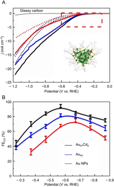 | ||
| Fig. 23 (A) LSV curves of Au47Cd2(TBBT)31, Au44(TBBT)28 and the ca. 1.5 nm Au NPs in an Ar-saturated (dotted line) and a CO2-saturated (full line) 0.5 M KHCO3 solution; inset: total structure of the Au47Cd2(TBBT)31. Color labels: yellow = S; gray = C; red = Cd, others = Au. (B). FECO for the catalysts examined with different applied potentials. Panels (A) and (B) are reproduced with permission from ref. 306. Copyright 2019 Wiley-VCH Verlag GmbH & Co. KGaA, Weinheim. | ||
Kauffman, Mpourmpakis, and Jin et al. used [Au19Cd2(SC6H11)16]− and [Au23(SC6H11)16]− (ref. 206 and 307) to compare CRR activity.308 For [Au19Cd2(SC6H11)16]−, the CO selectivity of the CRR was ∼90–95% at applied potentials of −0.5 to −0.9 V vs. RHE, approximately twice that of [Au23(SC6H11)16]−. From the DFT calculations, similar to the previous study,16 it is thermodynamically preferable to remove the –R group from the NCs, compared with the –SR group. Therefore, they simplified the ligand to SCH3 and calculated the reaction free energy pathways using the two NCs, but with one ligand's R site removed ([Au19Cd2S(SCH3)15]− and [Au23S(SCH3)15]−). The thermodynamic energy barrier for CO formation was 0.74 eV lower for [Au19Cd2S(SCH3)15]− compared with [Au23S(SCH3)15]−. In addition, comparing the thermodynamic limiting steps of CRR and HER, the calculated results were consistent with the experimental data showing that [Au19Cd2S(SCH3)15]− has a higher CRR selectivity. The effect of solvation was also examined, and it was found that the solvent (water) only had a minimal effect on the reaction energy. These results showed that modifying both the NC surface morphology and electronic structure by Cd doping can significantly enhance CRR activity.
In 2021, Zhu and Chen et al. synthesized Au25(PET)18, Au24Cd(PET)18, Au19Cd3(S-tol)18, and Au38Cd4(d-MBT)30 and investigated the effect of different substitution positions of Cd doping on the catalytic CRR activity.188 As shown in Fig. 3Ba, the Cd atoms in Au24Cd(PET)18 replaced the Au atoms located in the core–shell layer, and the Cd atoms in Au19Cd3(S-tol)18 and Au38Cd4(d-MBT)30 substituted the Au atoms on the shell staples. Among these four NCs, Au24Cd(PET)18 showed the highest current density, FECO, and jCO, whereas Au19Cd3(S-tol)18 showed the lowest CRR activity (Fig. 24a–c). Fig. 24d and e shows that a small amount of HCOOH was detected in addition to the main product of CO, for all NCs. Furthermore, the stability measurements in Fig. 24f show that Au24Cd(PET)18 and Au19Cd3(S-tol)18 were highly stable, with no significant change in current density after 24 h. DFT calculations showed that removing the carbon chain on the NC surface (S–C cleavage) was advantageous for CRR, as observed in previous studies,16 and exposing the Au site by Au–S cleavage was advantageous for HER. From these results, it was speculated that only S–C cleavage occurs in Au24Cd(PET)18 and that the HER was suppressed by avoiding Cd–S cleavage, resulting in a high FECO. These results showed that the CRR activity can be enhanced by controlling the surface state through doping to different sites.
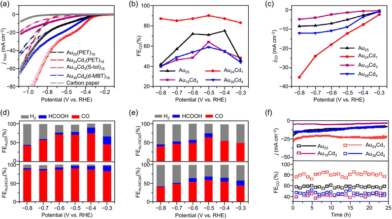 | ||
| Fig. 24 (a) LSV curves of Au25(PET)18, Au24Cd1(PET)18, Au19Cd3(S-tol)18 and Au38Cd4(d-MBT)30 under an Ar-saturated (dotted line) and a CO2-saturated (full line) in 1.0 M KHCO3 solution. (b) FECO for the catalysts examined with different applied potentials. (c) The corresponding jCO. (d) FEs for various CRR products obtained on Au25(PET)18 and Au24Cd1(PET)18 catalysts. (e) FEs for various CRR products obtained on Au19Cd3(S-tol)18 and Au38Cd4(d-MBT)30 catalysts. (f) The stability test conducted at −0.7 V vs. RHE for Au25(PET)18, Au24Cd1(PET)18, Au19Cd3(S-tol)18 and Au38Cd4(d-MBT)30 catalysts. These figures are reproduced with permission from ref. 188. Copyright 2021 American Chemical Society. | ||
In 2021, Lim, Yoo, and Lee et al. investigated the effect of Pt doping on CRR activity using [Au25(SC6H13)18]− and [PtAu24(SC6H13)18]0.309 [PtAu24(SC6H13)18]0 has a central atom of [Au25(SC6H13)18]− replaced by Pt, but otherwise, the overall structures are very similar (Fig. 3A). Comparing the electrocatalytic performance, [PtAu24(SC6H13)18]0 was found to promote HER more than CRR, compared with [Au25(SC6H13)18]− (Fig. 25a and b). As shown in Fig. 25c and d, in the 0.3–0.6 V vs. RHE range where CO formation is not controlled by the solubility of CO2, the FECO of [Au25(SC6H13)18]− was >95%, but [PtAu24(SC6H13)18]0 showed FEH2 = ∼80% at 0.4 V vs. the RHE. They also obtained a synthesis gas with a controlled H2/CO molar ratio of 1 to 4 by mixing [Au25(SC6H13)18]− and [PtAu24(SC6H13)18]0 on the gas diffusion electrode (GDE) with an appropriate mass ratio (Fig. 25e). Additionally, DFT calculations for the CRR and HER processes were performed with SC6H13 replaced by SCH3 for simplicity. As a result, the HER with [PtAu24(SCH3)18]0 was found to have an almost ideal *H bonding energy, which is favorable for HER. For [Au25(SCH3)18]−, the reaction is more active for the CRR because the limiting potential of the CRR (0.09 eV) is higher than that of the HER (0.32 eV). Therefore, it was revealed that the CRR is more likely to proceed for [Au25(SC6H13)18]− and the HER is more likely for [PtAu24(SC6H13)18]0.
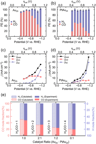 | ||
| Fig. 25 Results of FECO and FEH2 measured on the (a) Au25/C/GDE and (b) PtAu24/C/GDE in the CO2-saturated solution of 0.1 M KHCO3 and 0.4 M KCl at various applied potentials. The corresponding jtotal, jCO, and jH2 obtained on the (c) Au25/C/GDE and (d) PtAu24/C/GDE at various potentials. (e) Calculated (shaded) and experimentally determined (filled) H2/CO ratio on formulated Au25 and PtAu24 catalysts. These figures are reproduced with permission from ref. 309. Copyright 2021 AIP Publishing. | ||
In 2022, Zhou, Gao, and Zhu et al. synthesized [Au38(SCH2PhtBu)24]0, [PtAu37(SCH2PhtBu)24]0, and [Pt2Au36(SCH2PhtBu)24]0 with Pt doping of one or two atoms and investigated the effect of the Pt atomic position and number on the CRR catalytic activity.199 SC-XRD analysis revealed that [Au38(SCH2PhtBu)24]0 consists of a 23-atom kernel composed of two 13-atom icosahedra sharing one triangular plane, three Au(SR)2 staples around the icosahedra, and six Au2(SR)3 staples (Fig. 4B and 26A). In addition, theoretical calculations and X-ray absorption fine structure analysis suggested that the position of Pt in [PtAu37(SCH2PhtBu)24]0 and [Pt2Au36(SCH2PhtBu)24]0 is at the center of the icosahedron. From time-dependent DFT (TDDFT) calculations, [PtAu37(SH)24]0 has one less total electron than [Au38(SH)24]0, and the highest occupied molecular orbital (HOMO) energy increases. In contrast, in [Pt2Au36(SH)24]0, the total number of electrons is decreased by two compared with [Au38(SH)24]0, and the HOMO of [Pt2Au36(SH)24]0 changes to an orbital corresponding to the HOMO−1 of [Au38(SH)24]0, which results in a narrower HOMO-lowest unoccupied molecular orbital (LUMO) gap. This result suggests that [PtAu37(SH)24]0 is more likely to give electrons to reactants and [Pt2Au36(SH)24]0 is less likely to give electrons to reactants compared with [Au38(SH)24]0 in the reduction process. Evaluation of CRR activity with these NCs showed that [PtAu37(SCH2PhtBu)24]0 had the highest jCO and FECO (80% at −0.6 V vs. RHE) (Fig. 26B).
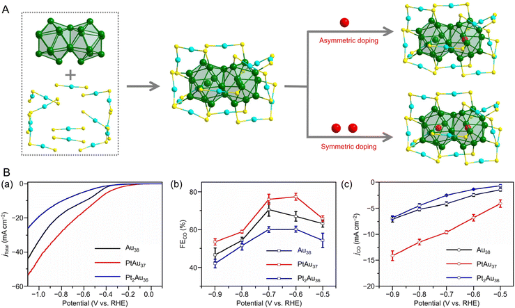 | ||
| Fig. 26 (A) Structural anatomy of [Au38(SR)24]0, asymmetrical [Pt1Au37(SR)24]0 and symmetrical [Pt2Au36(SR)24]0. Color labels: green/blue = Au, red = Pt, yellow = S. The C and H are omitted for clarify. (B) (a) LSV profiles of [Au38(SCH2PhtBu)24]0, [PtAu37(SCH2PhtBu)24]0 and [Pt2Au36(SCH2PhtBu)24]0 catalysts in a 0.5 M KHCO3 solution. (b) FECO and (c) jCO for [Au38(SCH2PhtBu)24]0, [PtAu37(SCH2PhtBu)24]0 and [Pt2Au36(SCH2PhtBu)24]0 catalysts at different applied potentials. Error bars correspond to the deviations from several independent experiments. (A) and (B) are reproduced with permission from ref. 199. Copyright 2022 Wiley-VCH GmbH. | ||
In 2022, Zhu et al. synthesized Ag4+xAu40−x(C![[triple bond, length as m-dash]](https://www.rsc.org/images/entities/char_e002.gif) CPh(CH3)2)28 (HC
CPh(CH3)2)28 (HC![[triple bond, length as m-dash]](https://www.rsc.org/images/entities/char_e002.gif) CPh(CH3)2 = 1-ethynyl-2,4-dimethylbenzene), and they investigated the effect of Ag doping in CRRs using Au44(C
CPh(CH3)2 = 1-ethynyl-2,4-dimethylbenzene), and they investigated the effect of Ag doping in CRRs using Au44(C![[triple bond, length as m-dash]](https://www.rsc.org/images/entities/char_e002.gif) CPh(CH3)2)28, Au44(d-MBT)28, and Ag4+xAu40−x(C
CPh(CH3)2)28, Au44(d-MBT)28, and Ag4+xAu40−x(C![[triple bond, length as m-dash]](https://www.rsc.org/images/entities/char_e002.gif) CPh(CH3)2)28.310 When electrolytic reduction was performed in a 0.5 M KHCO3 solution saturated with CO2, the main products of the three NCs were CO and a small amount of H2. In particular, Ag4+xAu40−x(C
CPh(CH3)2)28.310 When electrolytic reduction was performed in a 0.5 M KHCO3 solution saturated with CO2, the main products of the three NCs were CO and a small amount of H2. In particular, Ag4+xAu40−x(C![[triple bond, length as m-dash]](https://www.rsc.org/images/entities/char_e002.gif) CPh(CH3)2)28 exhibited the highest current density, and the FECO reached approximately 98% (−0.5 V vs. RHE). They also measured electrochemical impedance and electrochemical surface area to determine the reason for the differences in their catalytic performance. It was suggested that Ag doping decreased the charge transfer resistance and increased the number of active sites, thereby enhancing CRR activity.
CPh(CH3)2)28 exhibited the highest current density, and the FECO reached approximately 98% (−0.5 V vs. RHE). They also measured electrochemical impedance and electrochemical surface area to determine the reason for the differences in their catalytic performance. It was suggested that Ag doping decreased the charge transfer resistance and increased the number of active sites, thereby enhancing CRR activity.
In 2022, Kim, Yoo, and Lee et al. used [Au25(PET)18]−, [Ag25(SPhMe2)18]−, and bimetallic [AuAg12@Au12(PET)18]− with a core–shell structure for CRR activity.190 Comparing the CRR and HER activities of [Au25(PET)18]− and [Ag25(SPhMe2)18]− activated by de-thiolation, the jCO was found to be higher than jH2 for both NCs. To investigate the origin of the CRR activity, DFT calculations were conducted (ligands were replaced with SCH3 for simplicity). As a result, the partially de-thiolated sites, the bridging core metal, and the SR ligand in both NCs were determined to be the CRR active sites. The CRR limiting potential of [Au25(PET)18]− (0.14 V) is lower than that of [Ag25(SPhMe2)18]− (0.24 V). The reason for the superior CRR activity of [Au25(PET)18]− might be that the stabilization of *COOH promoted more activation of CO2. Therefore, they replaced the Ag12(SR)18 shell, the active site in [Ag25(SPhMe2)18]−, with the more active Au12(SR)18 shell to improve the CRR activity. After optimizing the synthesis conditions, they obtained [AuAg12@Au12(PET)18]− consisting of an AuAg12 core and an Au12(PET)18 protective shell (Fig. 3C). Then, the CRR activity was evaluated using the alloy NCs activated by de-thiolation. The jCO of [AuAg12@Au12(PET)18]− was found to be similar to that of [Au25(PET)18]−, and the FECO was slightly lower than that of [Au25(PET)18]−. Furthermore, the long-term stability of [AuAg12@Au12(PET)18]− was confirmed using a zero-gap CO2 electrolyzer. When galvanostatic electrolysis was performed at a current density of 200 mA cm−2, the full cell potential of the electrolyzer maintained 2.13 ± 0.03 V and 57% FECO for 24 h for [AuAg12@Au12(PET)18]−.
In 2022, Yang, Yang, and Wu et al. reported Au–Pd–Ag trimetallic alloy NCs. They showed the effect of Ag doping in CRRs using similar structures protected with TBBT (Fig. 5), namely Au4Pd6(TBBT)12 and Au3AgPd6(TBBT)12.202 The LSV curves indicated that Au3AgPd6(TBBT)12 exhibits a higher current density than Au4Pd6(TBBT)12, suggesting that Ag doping enhances the catalytic CRR activity. The maximum FECO of Au3AgPd6(TBBT)12 was 94.1% (at −0.57 V vs. RHE), which was higher than that of Au4Pd6(TBBT)12 (88.1% at −0.67 V vs. RHE). Furthermore, Au3AgPd6(TBBT)12 showed high long-term stability, and no decrease in current density or selectivity was observed after 65 h of electrolysis (−0.57 V vs. RHE). They used DFT calculations to investigate the effect of Ag doping on the reaction mechanism. Notably, the increase in the free energy of CO desorption was smaller for Au3AgPd6(SCH3)11 than for Au4Pd6(SCH3)11, which suggests that Ag doping into Au4Pd6(SCH3)11 weakens the binding energy of *CO on the active site and promotes CO desorption, thereby improving the reduction to CO. This may be attributed to the electronic effects caused by the substitution of Ag atoms. From the XPS spectra, the binding energies of Au 4f and Pd 3d of Au3AgPd6(TBBT)12 were significantly higher than those of Au4Pd6(TBBT)12, which explained why the *CO adsorption on the active site of Au3AgPd6(SCH3)11 was weaker. Furthermore, this electronic effect might suppress the competitive HER. Therefore, Au3AgPd6(SCH3)11 showed high selectivity as an electrocatalyst for the reduction of CO2 to CO owing to the more difficult desorption of H*. These results demonstrated that Ag doping can affect the electronic structure of NCs and enhance CRR activity.
In 2020, Kauffman, Mpourmpakis, and Jin et al. evaluated the electrocatalytic activity of CRRs using [Au24Pd(PET)18]0 and [Au25(PET)18]0 (Fig. 27A).311 [Au25(PET)18]0 showed an FECO of ∼100% below −0.9 V vs. RHE. However, at more negative potentials, the FECO began to decrease (approximately 60% at −1.2 V vs. RHE; Fig. 27A). In contrast, [Au24Pd(PET)18]0 maintained ∼100% FECO over a much wider potential range and showed almost complete HER suppression up to −1.2 V vs. RHE. The jCO and mass activity of CO showed that [Au24Pd(PET)18]0 was more active than [Au25(PET)18]0 at all potentials. The mass activity of [Au24Pd(PET)18]0 (∼1770 mA mg−1) was approximately twice as high as [Au25(PET)18]0 (∼980 mA mg−1) at −1.2 V vs. RHE. Considering that only one Au atom is replaced by a Pd atom, the above results indicate that the doping effect of different elements plays an important role in CO production. No change in absorption spectrum was observed in [Au24Pd(PET)18]0, even after 6 h of electrolysis at −0.8 V vs. RHE, demonstrating its stability. From the DFT calculations, the thermodynamic limiting potentials (UL) in CRRs and HERs for [Au24Pd(SCH3)18]0 and [Au25(SCH3)18]0 were calculated (Fig. 27B). Fully ligand-protected NCs were electrochemically inactive and had relatively large UL (CRR) values. However, the NCs were activated when some Au and S atom sites were exposed, such that the Au13 core can act as an electron reservoir. From the calculated ΔUL, Au24PdS(SCH3)17 with the active site at the S atom was predicted to show the most selective activity for the CRR.
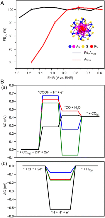 | ||
| Fig. 27 (A) Electrocatalytic CO2 reduction performance (FECO) of [Au25(PET)18]0 and [Au24Pd(PET)18]0; inset: atom packing structures of [Au24Pd(PET)18]0 (–R groups omitted for clarity). (B) Free-energy diagrams for electrochemical (a) CRR and (b) HER at U = 0 V vs. RHE of [Au24Pd(SCH3)18]0 and [Au25(SCH3)18]0. Panels (A) and (B) are reproduced with permission from ref. 311. Copyright 2020 American Chemical Society. | ||
From these reports, it became clear that (1) Ag, Cd, and Pd doping to Au NCs tends to improve CRR activity and selectivity, and (2) Pt doping may improve HER selectivity. Such a doping effect is considered to depend also on the geometric/electronic structure of the Au NCs.
3.4 Electrocatalytic CO2 reduction reactions using silver nanoclusters
Among the precious metals, Ag is relatively inexpensive and abundant. Furthermore, it has attracted attention in CRRs because of its high selectivity for CO formation.202,314 The reported cases of Ag-based NCs used in CRRs are summarized in Table 6.| Nanocluster/nanoparticle | Electrolytes | Electrolyzer | Main product | Selectivity (@V vs. RHE) | Current density (mA cm−2@V vs. RHE) | Stability (@V vs. RHE) | Ref. |
|---|---|---|---|---|---|---|---|
| iPr = isopropyl, EMIM-BF4 = 1-ethyl-3-methylimidazolium tetrafluoroborate, S-Adm = 1-adamantanethiolate, SPhMe2 = 2,4-dimethylbenzenethiolate, DPPE = 1,2-bis(diphenylphosphino)ethane, TC4A = thiacalix[4]arene, DPPP = 1,3-bis(diphenylphosphino)propane, MEA = membrane electrode assembly.a vs. MEA-cell potential.b Vulcan XC-72R.c Multi-walled carbon nanotube.d Acetylene black.e Ketjen black (EC-600JD).f Hydrophobic carbon paper.g Carbon paper (Toray TGP-H-090).h Carbon paper. | |||||||
[Ag15(C![[triple bond, length as m-dash]](https://www.rsc.org/images/entities/char_e002.gif) CtBu)12]+ CtBu)12]+ |
0.5 M KHCO3 aq. | H-cell | CO | ∼95%@−0.6 | 13.0@−0.9 | 10 h@−0.75 |
258![[thin space (1/6-em)]](https://www.rsc.org/images/entities/char_2009.gif) b b |
Ag32(C![[triple bond, length as m-dash]](https://www.rsc.org/images/entities/char_e002.gif) CPh(CF3)2)24 CPh(CF3)2)24 |
0.5 M NaHCO3 aq. | H-cell | CO | 96.44%@−0.8 | 9.05@−1.0 | 15 h |
260![[thin space (1/6-em)]](https://www.rsc.org/images/entities/char_2009.gif) c c |
| [Ag32(DPPE)5(SC6H4CF3)24]2− | 56.67%@−1.0 | N/A | 15 h | ||||
| (Mo6O22)@H3Ag49(MO3)9(MoO4)–(TC4A)6(iPrS)18(CH3CN)2(H2O) | 0.5 M KHCO3 aq. | H-cell | H2 | ∼54%@−0.8 | N/A | 5 h@−0.8 |
266![[thin space (1/6-em)]](https://www.rsc.org/images/entities/char_2009.gif) d d |
| CO | 44.75%@−0.8 | 4@−0.8 | |||||
[Au7Ag8(C![[triple bond, length as m-dash]](https://www.rsc.org/images/entities/char_e002.gif) CtBu)12]+ CtBu)12]+ |
1.0 M KOH aq. | Flow cell | CO | ∼90%@−0.19 | ∼160@−0.19 | 10 h @−0.49 |
245![[thin space (1/6-em)]](https://www.rsc.org/images/entities/char_2009.gif) c c |
| HCOOH | 0%@−1.19 | 0@−0.19 | |||||
[Ag9Cu6(C![[triple bond, length as m-dash]](https://www.rsc.org/images/entities/char_e002.gif) CtBu)12]+ CtBu)12]+ |
CO | ∼25%@−1.19 | ∼30@−0.19 | 10 h @−1.19 | |||
| HCOOH | ∼47%@−1.19 | ∼50@−0.19 | |||||
[Au2Ag8Cu5(C![[triple bond, length as m-dash]](https://www.rsc.org/images/entities/char_e002.gif) CtBu)12]+ CtBu)12]+ |
CO | ∼25%@−1.19 | ∼30@−0.19 | 10 h @−0.99 | |||
| HCOOH | ∼20%@−1.19 | ∼25@−0.19 | |||||
[Ag15Cu6(C![[triple bond, length as m-dash]](https://www.rsc.org/images/entities/char_e002.gif) CPh(CF3)2)18(DPPE)2]− CPh(CF3)2)18(DPPE)2]− |
0.1 M KHCO3 aq. | H-cell | CO | 91.3%@−0.81 | −60@−3.25a | 145 h@−3.25a |
263![[thin space (1/6-em)]](https://www.rsc.org/images/entities/char_2009.gif) e e |
[Ag9Cu6(C![[triple bond, length as m-dash]](https://www.rsc.org/images/entities/char_e002.gif) CtBu)12]+ CtBu)12]+ |
MEA-cell | 48.5%@−0.89 | N/A | ||||
| [AuAg26(S-Adm)18S]− | EMIM-BF4/H2O (v/v = 7![[thin space (1/6-em)]](https://www.rsc.org/images/entities/char_2009.gif) : :![[thin space (1/6-em)]](https://www.rsc.org/images/entities/char_2009.gif) 1) + 0.5 M H2SO4 1) + 0.5 M H2SO4 |
H-cell | CO | 98.4%@−0.97 | 8@−0.97 | 11 h @−0.97 |
255![[thin space (1/6-em)]](https://www.rsc.org/images/entities/char_2009.gif) c c |
| [Ag25(SPhMe2)18]− | ∼60%@−0.97 | 3@−0.97 | N/A | ||||
| Au21(S-Adm)16 | ∼5.0%@−0.97 | 1@−0.97 | N/A | ||||
| Ag40.63Cu9.37(SC7H7O)32 | 2 M KOH aq. | Flow cell | C1 product | ∼58%@−0.57 | ∼3.0@−0.57 | N/A |
254![[thin space (1/6-em)]](https://www.rsc.org/images/entities/char_2009.gif) f f |
| C2 product | 29.5%@−0.57 | −2.24@−0.57 | |||||
| Ag36.14Cu13.86(SC7H7O)32 | C1 product | ∼40%@−0.57 | ∼2.1@−0.57 | 14 h@−0.57 | |||
| C2 product | 47.5%@−0.57 | −3.04@−0.57 | |||||
| ∼5 nm Ag NP | N/A | N/A | N/A | N/A | |||
Au24Ag20(C![[triple bond, length as m-dash]](https://www.rsc.org/images/entities/char_e002.gif) CtBu)24Cl2 CtBu)24Cl2 |
0.5 M KHCO3 aq. | H-cell | CO | ∼90%@−0.5 | 25@−0.8 | N/A |
315![[thin space (1/6-em)]](https://www.rsc.org/images/entities/char_2009.gif) g g |
Au24Ag20(C![[triple bond, length as m-dash]](https://www.rsc.org/images/entities/char_e002.gif) CPhC)24Cl2 CPhC)24Cl2 |
∼90%@−0.5 | 17.5@−0.8 | N/A | ||||
[Au43Ag38(C![[triple bond, length as m-dash]](https://www.rsc.org/images/entities/char_e002.gif) CtBu)36Cl12]+ CtBu)36Cl12]+ |
∼80%@−0.5 | 7.5@−0.8 | N/A | ||||
[Au43Ag38(C![[triple bond, length as m-dash]](https://www.rsc.org/images/entities/char_e002.gif) CPhC)36Cl9]+ CPhC)36Cl9]+ |
∼70%@−0.5 | 5@−0.8 | N/A | ||||
| [Au8Ag55(DPPP)4(SC6H11)34]2+ | 0.5 M KHCO3 aq. | H-cell | CO | ∼67%@−0.8 | ∼14@−0.8 | 9 h@−0.8 |
316![[thin space (1/6-em)]](https://www.rsc.org/images/entities/char_2009.gif) h h |
| H2 | ∼25%@−0.8 | N/A | |||||
| [Au8Ag57(DPPP)4(SC6H11)32Cl2]+ | CO | ∼62%@−0.8 | ∼8@−0.8 | N/A | |||
| H2 | ∼25%@−0.8 | N/A | |||||
| [Au12Ag60(DPPP)6(SC6H11)31Br9]2+ | CO | ∼46%@−0.8 | ∼5@−0.8 | N/A | |||
| H2 | ∼45%@−0.8 | N/A | |||||
In 2021, Tang, Jin, and Tang et al. evaluated CRR activity using [Ag15(C![[triple bond, length as m-dash]](https://www.rsc.org/images/entities/char_e002.gif) CtBu)12]+ as an electrocatalyst.258Fig. 28A shows the ESI-MS spectrum and geometric structure of [Ag15(C
CtBu)12]+ as an electrocatalyst.258Fig. 28A shows the ESI-MS spectrum and geometric structure of [Ag15(C![[triple bond, length as m-dash]](https://www.rsc.org/images/entities/char_e002.gif) CtBu)12]+, which comprises a bcc structure with a metal core configuration of Ag@Ag8@Ag6. [Ag15(C
CtBu)12]+, which comprises a bcc structure with a metal core configuration of Ag@Ag8@Ag6. [Ag15(C![[triple bond, length as m-dash]](https://www.rsc.org/images/entities/char_e002.gif) CtBu)12]+ was first mixed with the conductive support, CB, in a 2
CtBu)12]+ was first mixed with the conductive support, CB, in a 2![[thin space (1/6-em)]](https://www.rsc.org/images/entities/char_2009.gif) :
:![[thin space (1/6-em)]](https://www.rsc.org/images/entities/char_2009.gif) 1 ratio before the CRR evaluation. As shown in Fig. 28B(a), the main product of CRRs was CO in the applied voltage range from −0.5 to −1.1 V vs. RHE. FECO remained above 90% over the potential range of −0.6 to −0.9 V vs. RHE and reached approximately 95% at −0.6 V vs. RHE. The partial current densities of CO and H2 increased with overvoltage, and the maximum TOF value was 6.37 s−1 at −1.1 V vs. RHE. Furthermore, constant potential measurements showed that the current density of the [Ag15(C
1 ratio before the CRR evaluation. As shown in Fig. 28B(a), the main product of CRRs was CO in the applied voltage range from −0.5 to −1.1 V vs. RHE. FECO remained above 90% over the potential range of −0.6 to −0.9 V vs. RHE and reached approximately 95% at −0.6 V vs. RHE. The partial current densities of CO and H2 increased with overvoltage, and the maximum TOF value was 6.37 s−1 at −1.1 V vs. RHE. Furthermore, constant potential measurements showed that the current density of the [Ag15(C![[triple bond, length as m-dash]](https://www.rsc.org/images/entities/char_e002.gif) CtBu)12]+ catalyst decreased only slightly after 10 h of continuous operation at −0.75 V vs. RHE, indicating high long-term stability (Fig. 28Bb). Next, to elucidate the electrocatalytic mechanism, the optimal catalytic site on [Ag15(C
CtBu)12]+ catalyst decreased only slightly after 10 h of continuous operation at −0.75 V vs. RHE, indicating high long-term stability (Fig. 28Bb). Next, to elucidate the electrocatalytic mechanism, the optimal catalytic site on [Ag15(C![[triple bond, length as m-dash]](https://www.rsc.org/images/entities/char_e002.gif) CCH3)12]+ was determined by DFT calculations, and the selectivities of the reduction products were compared. As a result, the formation of *COOH was the rate-limiting step in [Ag15(C
CCH3)12]+ was determined by DFT calculations, and the selectivities of the reduction products were compared. As a result, the formation of *COOH was the rate-limiting step in [Ag15(C![[triple bond, length as m-dash]](https://www.rsc.org/images/entities/char_e002.gif) CCH3)12]+, and the formation of H2 was energetically favorable (Fig. 28Ca). However, with one ligand removed ([Ag15(C
CCH3)12]+, and the formation of H2 was energetically favorable (Fig. 28Ca). However, with one ligand removed ([Ag15(C![[triple bond, length as m-dash]](https://www.rsc.org/images/entities/char_e002.gif) CCH3)11]+), the appearance of an Ag active site is favorable for the formation of *COOH and significantly lowers the energy barrier for the formation of *COOH and promotes CRR activity (Fig. 28Cb).
CCH3)11]+), the appearance of an Ag active site is favorable for the formation of *COOH and significantly lowers the energy barrier for the formation of *COOH and promotes CRR activity (Fig. 28Cb).
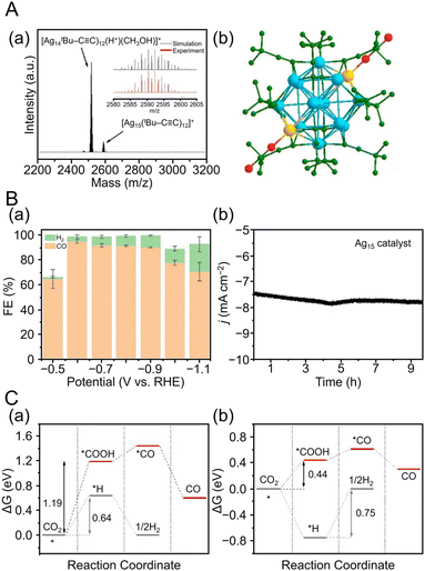 | ||
Fig. 28 (A) (a) the ESI-MS spectra and (b) the overall structure of [Ag15(C![[triple bond, length as m-dash]](https://www.rsc.org/images/entities/char_e002.gif) CtBu)12]+. (B) (a) Faradaic efficiency at various applied potentials over [Ag15(C CtBu)12]+. (B) (a) Faradaic efficiency at various applied potentials over [Ag15(C![[triple bond, length as m-dash]](https://www.rsc.org/images/entities/char_e002.gif) CtBu)12]+ in aqueous solution of 0.5 M KHCO3. (b) Stability of [Ag15(C CtBu)12]+ in aqueous solution of 0.5 M KHCO3. (b) Stability of [Ag15(C![[triple bond, length as m-dash]](https://www.rsc.org/images/entities/char_e002.gif) CtBu)12]+ for CO2 reduction at −0.75 V vs. RHE. (C) Comparison of ΔG of electroreduction of CO2 to CO vs. HER on (a) [Ag15(C CtBu)12]+ for CO2 reduction at −0.75 V vs. RHE. (C) Comparison of ΔG of electroreduction of CO2 to CO vs. HER on (a) [Ag15(C![[triple bond, length as m-dash]](https://www.rsc.org/images/entities/char_e002.gif) CCH3)12]+, (b) [Ag15(C CCH3)12]+, (b) [Ag15(C![[triple bond, length as m-dash]](https://www.rsc.org/images/entities/char_e002.gif) CCH3)11]+. (A)–(C) are reproduced with permission from ref. 258. Copyright 2021 Wiley-VCH GmbH. CCH3)11]+. (A)–(C) are reproduced with permission from ref. 258. Copyright 2021 Wiley-VCH GmbH. | ||
![[triple bond, length as m-dash]](https://www.rsc.org/images/entities/char_e002.gif) CtBu)24Cl2 (Au24Ag20-1) and Au24Ag20(C
CtBu)24Cl2 (Au24Ag20-1) and Au24Ag20(C![[triple bond, length as m-dash]](https://www.rsc.org/images/entities/char_e002.gif) CPhC)24Cl2 (Au24Ag20-2; HC
CPhC)24Cl2 (Au24Ag20-2; HC![[triple bond, length as m-dash]](https://www.rsc.org/images/entities/char_e002.gif) CPhC = 2-methylphenylacetylene), and two dimeric compounds, such as Au43Ag38(C
CPhC = 2-methylphenylacetylene), and two dimeric compounds, such as Au43Ag38(C![[triple bond, length as m-dash]](https://www.rsc.org/images/entities/char_e002.gif) CtBu)36Cl12 (Au43Ag38-1) and Au43Ag38(C
CtBu)36Cl12 (Au43Ag38-1) and Au43Ag38(C![[triple bond, length as m-dash]](https://www.rsc.org/images/entities/char_e002.gif) CPhC)36Cl9 (Au43Ag38-2).315 The monomer NCs (Au24Ag20-1 and 2) have a similar core structure containing icosahedral Ag12 surrounded by Ag20. These two Au24Ag20 monomers self-assemble in different growth modes to form two different dimers: Au43Ag38-1 and Au43Ag38-2. The catalytic ability of these monomers and dimers for CRRs was examined, with the Au24Ag20 monomer exhibiting higher jCO and FECO than the Au43Ag38 dimer. Among all four species, Au24Ag20-1 showed the highest CRR activity, and Au43Ag38-2 showed the lowest CRR activity. Electrochemical impedance measurements suggest that the Au24Ag20 monomer has faster charge transfer than the Au43Ag38 dimer. Structural effects have also been investigated using metal NCs with different chemical compositions. Although [Au8Ag55(DPPP)4(SC6H11)34](BPh4)2, [Au8Ag57(DPPP)4(SC6H11)32Cl2]Cl, [Au12Ag60(DPPP)6(SC6H11)31Br9]Br2 are similar in size and structure, their different assembly structures lead to significantly different CRR catalytic performances. Among the three NCs, [Au8Ag55(DPPP)4(SC6H11)34] were found to have strong CO2 adsorption capacity and exhibit the best CRR performance due to charge segregation placing Ag atoms on the outer side of Au8.316
CPhC)36Cl9 (Au43Ag38-2).315 The monomer NCs (Au24Ag20-1 and 2) have a similar core structure containing icosahedral Ag12 surrounded by Ag20. These two Au24Ag20 monomers self-assemble in different growth modes to form two different dimers: Au43Ag38-1 and Au43Ag38-2. The catalytic ability of these monomers and dimers for CRRs was examined, with the Au24Ag20 monomer exhibiting higher jCO and FECO than the Au43Ag38 dimer. Among all four species, Au24Ag20-1 showed the highest CRR activity, and Au43Ag38-2 showed the lowest CRR activity. Electrochemical impedance measurements suggest that the Au24Ag20 monomer has faster charge transfer than the Au43Ag38 dimer. Structural effects have also been investigated using metal NCs with different chemical compositions. Although [Au8Ag55(DPPP)4(SC6H11)34](BPh4)2, [Au8Ag57(DPPP)4(SC6H11)32Cl2]Cl, [Au12Ag60(DPPP)6(SC6H11)31Br9]Br2 are similar in size and structure, their different assembly structures lead to significantly different CRR catalytic performances. Among the three NCs, [Au8Ag55(DPPP)4(SC6H11)34] were found to have strong CO2 adsorption capacity and exhibit the best CRR performance due to charge segregation placing Ag atoms on the outer side of Au8.316
![[triple bond, length as m-dash]](https://www.rsc.org/images/entities/char_e002.gif) CR ligands have been used by Wang et al. for the semihydrogenation of alkyne317 and by Tsukuda et al. for the HER318 to enhance the activity of these reactions, and similar enhancements have also been expected for CRRs. In 2022, Tang, Wang, and Tang et al. compared the effect of ligands in CRRs using Ag32(C
CR ligands have been used by Wang et al. for the semihydrogenation of alkyne317 and by Tsukuda et al. for the HER318 to enhance the activity of these reactions, and similar enhancements have also been expected for CRRs. In 2022, Tang, Wang, and Tang et al. compared the effect of ligands in CRRs using Ag32(C![[triple bond, length as m-dash]](https://www.rsc.org/images/entities/char_e002.gif) CPh(CF3)2)24 and [Ag32(DPPE)5(SC6H4CF3)24]2−.260 In this case, Ag32(C
CPh(CF3)2)24 and [Ag32(DPPE)5(SC6H4CF3)24]2−.260 In this case, Ag32(C![[triple bond, length as m-dash]](https://www.rsc.org/images/entities/char_e002.gif) CPh(CF3)2)24 is composed of an Ag17 kernel. [Ag32(DPPE)5(SC6H4CF3)24]2− also has an Ag17 kernel, although the overall geometric structure and the number of ligands are different. When catalysts were prepared by mixing both NCs with CNTs in the ratio of 2
CPh(CF3)2)24 is composed of an Ag17 kernel. [Ag32(DPPE)5(SC6H4CF3)24]2− also has an Ag17 kernel, although the overall geometric structure and the number of ligands are different. When catalysts were prepared by mixing both NCs with CNTs in the ratio of 2![[thin space (1/6-em)]](https://www.rsc.org/images/entities/char_2009.gif) :
:![[thin space (1/6-em)]](https://www.rsc.org/images/entities/char_2009.gif) 1, respectively, and evaluated for CRR activity, CO and H2 were the main products. The FECO was 96.44% at −0.8 V vs. RHE for Ag32(C
1, respectively, and evaluated for CRR activity, CO and H2 were the main products. The FECO was 96.44% at −0.8 V vs. RHE for Ag32(C![[triple bond, length as m-dash]](https://www.rsc.org/images/entities/char_e002.gif) CPh(CF3)2)24, but it was only 56.67% at −1.0 V vs. RHE for [Ag32(DPPE)5(SC6H4CF3)24]2− (Fig. 29A(a and b)). Furthermore, as shown in Fig. 29A(c and d), the overall CO and H2 partial current densities in both NCs showed gradually increasing trends when the potential was more negative. DFT calculations were performed to clarify how the CRR activity was affected by different ligands (C
CPh(CF3)2)24, but it was only 56.67% at −1.0 V vs. RHE for [Ag32(DPPE)5(SC6H4CF3)24]2− (Fig. 29A(a and b)). Furthermore, as shown in Fig. 29A(c and d), the overall CO and H2 partial current densities in both NCs showed gradually increasing trends when the potential was more negative. DFT calculations were performed to clarify how the CRR activity was affected by different ligands (C![[triple bond, length as m-dash]](https://www.rsc.org/images/entities/char_e002.gif) CCH3, P2C2H6, and SCH3 were used as ligands to simplify the calculations). As a result, Ag32(C
CCH3, P2C2H6, and SCH3 were used as ligands to simplify the calculations). As a result, Ag32(C![[triple bond, length as m-dash]](https://www.rsc.org/images/entities/char_e002.gif) CCH3)24 and [Ag32(P2C2H6)5(SCH3)24]2− have large free energy barriers (1.28 and 1.23 eV, respectively), but when one C
CCH3)24 and [Ag32(P2C2H6)5(SCH3)24]2− have large free energy barriers (1.28 and 1.23 eV, respectively), but when one C![[triple bond, length as m-dash]](https://www.rsc.org/images/entities/char_e002.gif) CCH3 or SCH3 is removed, the thermodynamic barrier to *COOH formation is decreased (0.40 and 0.50 eV, respectively) and CRR activity is enhanced (Fig. 29B and C). Ag32(C
CCH3 or SCH3 is removed, the thermodynamic barrier to *COOH formation is decreased (0.40 and 0.50 eV, respectively) and CRR activity is enhanced (Fig. 29B and C). Ag32(C![[triple bond, length as m-dash]](https://www.rsc.org/images/entities/char_e002.gif) CCH3)23 also has a higher thermodynamic barrier to H* for H2 formation than [Ag32(P2C2H6)5(SCH3)23]2−. This HER suppression suggests that Ag32(C
CCH3)23 also has a higher thermodynamic barrier to H* for H2 formation than [Ag32(P2C2H6)5(SCH3)23]2−. This HER suppression suggests that Ag32(C![[triple bond, length as m-dash]](https://www.rsc.org/images/entities/char_e002.gif) CPh(CF3)2)24 has a high selectivity for CO2 to CO.
CPh(CF3)2)24 has a high selectivity for CO2 to CO.
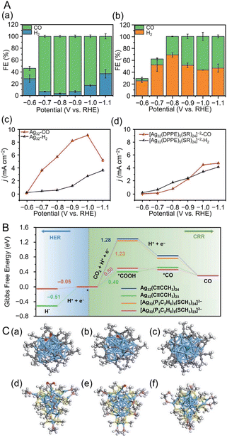 | ||
Fig. 29 (A) Faradaic efficiency of CO and H2 for (a) Ag32(C![[triple bond, length as m-dash]](https://www.rsc.org/images/entities/char_e002.gif) CPh(CF3)2)24 and (b) [Ag32(DPPE)5(SC6H4CF3)24]2− at different applied voltages. Partial current densities of CO and H2 for (c) Ag32(C CPh(CF3)2)24 and (b) [Ag32(DPPE)5(SC6H4CF3)24]2− at different applied voltages. Partial current densities of CO and H2 for (c) Ag32(C![[triple bond, length as m-dash]](https://www.rsc.org/images/entities/char_e002.gif) CPh(CF3)2)24 and (d) [Ag32(DPPE)5(SC6H4CF3)24]2− at different applied voltages (electrolyte: 0.5 M NaHCO3 aq.). (B) Change of reaction free energy (ΔG) at each fundamental step of CRR and HER for two NCs and stripping of one intact ligand. (C) Adsorption structure of COOH*, CO*, and H* intermediates on (a–c) [Ag32(C CPh(CF3)2)24 and (d) [Ag32(DPPE)5(SC6H4CF3)24]2− at different applied voltages (electrolyte: 0.5 M NaHCO3 aq.). (B) Change of reaction free energy (ΔG) at each fundamental step of CRR and HER for two NCs and stripping of one intact ligand. (C) Adsorption structure of COOH*, CO*, and H* intermediates on (a–c) [Ag32(C![[triple bond, length as m-dash]](https://www.rsc.org/images/entities/char_e002.gif) CCH3)23]+ and (d–f) [Ag32(P2C2H6)5(SCH3)23]−. Colour code: Ag, blue; C, gray; O, red; S, yellow; P, pin; H*, green and other H, white. (A)–(C) are reproduced with permission from ref. 260. Copyright 2022 Springer Nature. CCH3)23]+ and (d–f) [Ag32(P2C2H6)5(SCH3)23]−. Colour code: Ag, blue; C, gray; O, red; S, yellow; P, pin; H*, green and other H, white. (A)–(C) are reproduced with permission from ref. 260. Copyright 2022 Springer Nature. | ||
In 2023, Liu et al. synthesized a polymolybdate-templated Ag NC, [(Mo6O22)@H3Ag49(MO3)9(MoO4)–(TC4A)6(iPrS)18(CH3CN)2(H2O)] (Ag49Mo16 NC), by a solvothermal method and evaluated its CRR activity.266 As a result, the polymolybdate-templated Ag49Mo16 NC exhibited higher TOF values and jCO than (NH4)6Mo7O24, indicating that the Ag site is the active center of the CRR. The highest FECO was 44.75% at −0.8 V vs. RHE.
![[thin space (1/6-em)]](https://www.rsc.org/images/entities/char_2009.gif) :
:![[thin space (1/6-em)]](https://www.rsc.org/images/entities/char_2009.gif) 1) containing water saturated with CO2 showed that the main CO2 reduction products were CO and H2. Particularly, [AuAg26(S-Adm)18S]− showed the highest CO selectivity in the potential range from −0.82 to −1.12 V vs. RHE. The maximum FECO of [AuAg26(S-Adm)18S]− at −0.97 V vs. RHE was 98.4%, approximately 1.8 and 24 times higher than that of [Ag25(SPhMe2)18]− and Au21(S-Adm)16, respectively. The electrochemical stability of [AuAg26(S-Adm)18S]− was evaluated by chronopotentiometry at −0.97 V vs. RHE, which showed the highest CO selectivity, and the current density remained high with almost no decrease after 11 h of operation. In addition, they investigated the mechanism of catalytic selectivity by performing DFT calculations using SCH3 as a ligand. The *COOH formation energy barrier of [AuAg26(SCH3)18S]− (1.06 eV) was lower than that of [Ag25(SCH3)18]− (1.26 eV), Au21(SCH3)16 (1.83 eV), and [Ag27(SCH3)18S]− (1.11 eV). This suggested that Au doping of Ag NCs and the exposed core structure of [AuAg26(S-Adm)18S]− promoted CRR activity.
1) containing water saturated with CO2 showed that the main CO2 reduction products were CO and H2. Particularly, [AuAg26(S-Adm)18S]− showed the highest CO selectivity in the potential range from −0.82 to −1.12 V vs. RHE. The maximum FECO of [AuAg26(S-Adm)18S]− at −0.97 V vs. RHE was 98.4%, approximately 1.8 and 24 times higher than that of [Ag25(SPhMe2)18]− and Au21(S-Adm)16, respectively. The electrochemical stability of [AuAg26(S-Adm)18S]− was evaluated by chronopotentiometry at −0.97 V vs. RHE, which showed the highest CO selectivity, and the current density remained high with almost no decrease after 11 h of operation. In addition, they investigated the mechanism of catalytic selectivity by performing DFT calculations using SCH3 as a ligand. The *COOH formation energy barrier of [AuAg26(SCH3)18S]− (1.06 eV) was lower than that of [Ag25(SCH3)18]− (1.26 eV), Au21(SCH3)16 (1.83 eV), and [Ag27(SCH3)18S]− (1.11 eV). This suggested that Au doping of Ag NCs and the exposed core structure of [AuAg26(S-Adm)18S]− promoted CRR activity.
In 2023, Bootharaju, Tang, Hwang, and Hyeon et al. evaluated CRR activity using [Ag15Cu6(C![[triple bond, length as m-dash]](https://www.rsc.org/images/entities/char_e002.gif) CPh(CF3)2)18(DPPE)2]− as an electrocatalyst.263 Ag15Cu6 has a bcc-based structure with a core of Ag@Ag8@Ag2Cu4, as shown in Fig. 13C. For comparison, [Ag9Cu6(C
CPh(CF3)2)18(DPPE)2]− as an electrocatalyst.263 Ag15Cu6 has a bcc-based structure with a core of Ag@Ag8@Ag2Cu4, as shown in Fig. 13C. For comparison, [Ag9Cu6(C![[triple bond, length as m-dash]](https://www.rsc.org/images/entities/char_e002.gif) CtBu)12]+ (Ag9Cu6) and Ag15Cu6, which also have bcc structures and are similarly protected by C
CtBu)12]+ (Ag9Cu6) and Ag15Cu6, which also have bcc structures and are similarly protected by C![[triple bond, length as m-dash]](https://www.rsc.org/images/entities/char_e002.gif) CR, were loaded on Ketjen black (Ag15Cu6/C and Ag9Cu6/C, respectively) and evaluated for CRR catalytic activity. As a result, Ag15Cu6/C showed high FECO (>85%) in the potential range of −0.72 to −0.87 V vs. RHE, with the highest FECO of 91.3% at −0.81 V vs. RHE. In contrast, Ag9Cu6/C showed the highest FECO of 48.5% at −0.89 V vs. RHE. Moreover, a membrane electrode assembly (MEA) cell was used to evaluate CRR activity. FECO remained at ∼90% and jCO was −60 mA cm−2 during the 145 h electrolytic reaction, indicating that Ag9Cu6/C has high stability. From DFT calculations, it was revealed that the removal of one C
CR, were loaded on Ketjen black (Ag15Cu6/C and Ag9Cu6/C, respectively) and evaluated for CRR catalytic activity. As a result, Ag15Cu6/C showed high FECO (>85%) in the potential range of −0.72 to −0.87 V vs. RHE, with the highest FECO of 91.3% at −0.81 V vs. RHE. In contrast, Ag9Cu6/C showed the highest FECO of 48.5% at −0.89 V vs. RHE. Moreover, a membrane electrode assembly (MEA) cell was used to evaluate CRR activity. FECO remained at ∼90% and jCO was −60 mA cm−2 during the 145 h electrolytic reaction, indicating that Ag9Cu6/C has high stability. From DFT calculations, it was revealed that the removal of one C![[triple bond, length as m-dash]](https://www.rsc.org/images/entities/char_e002.gif) CCH3 exposes the ligand-deficient AgCu dual site and the thermodynamic barrier to *COOH formation was reduced. As a result, Ag15Cu6 with one desorbed C
CCH3 exposes the ligand-deficient AgCu dual site and the thermodynamic barrier to *COOH formation was reduced. As a result, Ag15Cu6 with one desorbed C![[triple bond, length as m-dash]](https://www.rsc.org/images/entities/char_e002.gif) CCH3 can proceed with a low energy barrier of 0.34 eV, associated with the desorption of *CO to CO. For the competing HER, the higher energy barrier of the H* desorption step (0.61 eV) to H2 evolution activity was also considered to enhance CO activity and selectivity.
CCH3 can proceed with a low energy barrier of 0.34 eV, associated with the desorption of *CO to CO. For the competing HER, the higher energy barrier of the H* desorption step (0.61 eV) to H2 evolution activity was also considered to enhance CO activity and selectivity.
In 2023, Wang, Yan, and Wu et al. evaluated CRR activity using Ag40.63Cu9.37(SC7H7O)32 [(AgCu)50-1] and Ag36.14Cu13.86(SC7H7O)32 [(AgCu)50-2].254 This is the first report of C2 production from CO2 reduction in the application of metal NCs as CRR catalysts. Both (AgCu)50 NCs also have a bimetallic M50 (M = Ag/Cu) core with fcc topology protected by 32 ligands of 3-methoxythiophenol. The catalytic CRR activity of (AgCu)50, as well as Ag NPs of ∼5 nm for comparison, was measured by flow cell in 2 M KOH electrolyte saturated with Ar and CO2. In the same potential range, the maximum FEC2 for (AgCu)50-1 and (AgCu)50-2 reached 29.5% and 47.5%, respectively, indicating a conversion in catalytic selectivity due to Cu substitution (Fig. 30Aa). Comparing the C2 and C1 partial current densities of both NCs, (AgCu)50-2 showed higher values (Fig. 30Aa). This improvement in FE was mainly due to ethanol production, with FECO in (AgCu)50-2 being 19% lower than that in (AgCu)50-1, and more C2 than CO was produced in (AgCu)50-2 (Fig. 30Ab). Comparing the FE ratios of C2/C1 for both NCs, (AgCu)50-2 reached a C2/C1 ratio of 1.2 at −0.57 V vs. RHE, indicating higher selectivity for the C2 compound. Furthermore, (AgCu)50-2 exhibited high stability, with FE remaining almost the same after long-term CRR activity at −0.57 V vs. RHE (Fig. 30B). DFT calculations showed that the Cu–Cu sites are thermodynamically more favorable than the Ag–Cu sites, such that (AgCu)50-2 with more Cu–Cu sites has relatively high selectivity for C2 products (Fig. 30C).
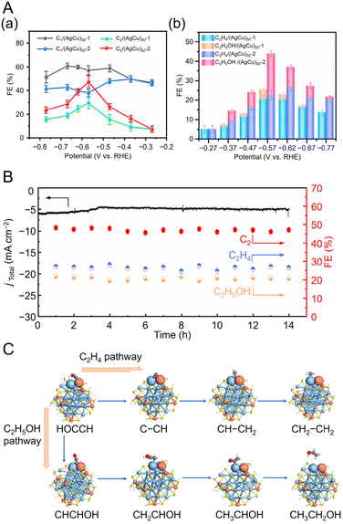 | ||
| Fig. 30 (A) CRR performance in a flow cell reactor. (a) C1 and C2 products FE on (AgCu)50-1 and (AgCu)50-2 at different potentials. (b) C2H4 and C2H5OH FE on (AgCu)50-1 or(AgCu)50-2 at different potentials. (B) Stability test of (AgCu)50-2 over 14 h of CO2 electrolysis in 2 M KOH at −0.57 V vs. RHE (the arrows indicate the corresponding axes). (C) Reaction pathway diagrams of Ag42Cu8 for the production of ethylene and ethanol at site 2 for DFT calculations. (A)–(C) are reproduced with permission from ref. 254. Copyright 2023 American Chemical Society. | ||
In 2022, Tang et al. investigated the effect of metal core alloying on CRR selectivity using C![[triple bond, length as m-dash]](https://www.rsc.org/images/entities/char_e002.gif) CR-protected bimetallic [Au7Ag8(C
CR-protected bimetallic [Au7Ag8(C![[triple bond, length as m-dash]](https://www.rsc.org/images/entities/char_e002.gif) CtBu)12]+ (Au7Ag8),244 [Au9Ag6(C
CtBu)12]+ (Au7Ag8),244 [Au9Ag6(C![[triple bond, length as m-dash]](https://www.rsc.org/images/entities/char_e002.gif) CtBu)12]+ (Au9Ag6),244 and trimetallic [Au2Ag8Cu5(C
CtBu)12]+ (Au9Ag6),244 and trimetallic [Au2Ag8Cu5(C![[triple bond, length as m-dash]](https://www.rsc.org/images/entities/char_e002.gif) CtBu)12]+ (Au2Ag8Cu5).245 Au7Ag8, Ag9Cu6, and Au2Ag8Cu5 have a core–shell–shell structures (Mcore@Mcube@Moctahedron), with core structures of Au1@Ag8@Au6, Ag1@Ag8@Cu6, and Au1@Au1Ag4Cu3@Ag4Cu2, respectively. Au7Ag8 only converted CO2 to CO, but Ag9Cu6 and Au2Ag8Cu5 converted CO and HCOOH, with maximum FEHCOOH values of 47.0% and 28.3%, respectively. From DFT calculations, the desorption of surface ligands exposed active metal sites, improving the selectivity and activity of the CRRs. Furthermore, the formation of surface hydrides played an important role in the formation and stabilization of HCOO* at the Au–Cu active center. Thus, the inclusion of Cu in the core structure led to a high selectivity of HCOOH. This report indicated that the selectivity of CRR products can be adjusted by controlling the metal core of C
CtBu)12]+ (Au2Ag8Cu5).245 Au7Ag8, Ag9Cu6, and Au2Ag8Cu5 have a core–shell–shell structures (Mcore@Mcube@Moctahedron), with core structures of Au1@Ag8@Au6, Ag1@Ag8@Cu6, and Au1@Au1Ag4Cu3@Ag4Cu2, respectively. Au7Ag8 only converted CO2 to CO, but Ag9Cu6 and Au2Ag8Cu5 converted CO and HCOOH, with maximum FEHCOOH values of 47.0% and 28.3%, respectively. From DFT calculations, the desorption of surface ligands exposed active metal sites, improving the selectivity and activity of the CRRs. Furthermore, the formation of surface hydrides played an important role in the formation and stabilization of HCOO* at the Au–Cu active center. Thus, the inclusion of Cu in the core structure led to a high selectivity of HCOOH. This report indicated that the selectivity of CRR products can be adjusted by controlling the metal core of C![[triple bond, length as m-dash]](https://www.rsc.org/images/entities/char_e002.gif) CR-protected metal NCs at the atomic level.
CR-protected metal NCs at the atomic level.
As mentioned above, it was clarified that Au or Cu doping to Ag NCs can greatly change the activity and selectivity of CRR.
3.5 Electrocatalytic CO2 reduction reactions using copper nanoclusters
Cu is attracting attention in electrocatalytic CRRs as a unique metal catalyst that can yield a variety of products by multi-electron reduction.319,320 Several cases of CRRs for Cu NCs,321–323 which are summarized in Table 7, have been reported.| Nanocluster/nanoparticle | Electrolytes | Electrolyzer | Main product | Selectivity (@V vs. RHE) | Current density (mA cm−2@V vs. RHE) | Stability (@V vs. RHE) | Ref. |
|---|---|---|---|---|---|---|---|
| BC = benzoic acid, iPr = isopropyl, PPh3 = triphenylphosphine, StBu = tert-butylthiolate, L1 = 9H-carbazole-9-carbodithioate, L2 = O-ethyl carbonodithiolate, MBO = 2-mercaptobenzoxazole, DPPE = 1,2-bis(diphenylphosphino)ethane, p-FPPh3 = tris(4-fluorophenyl)phosphine.a Vulcan XC-72.b Multi-walled carbon nanotube. | |||||||
Cu4Ti9O9(BC)18(OiPr)3(tBuC![[triple bond, length as m-dash]](https://www.rsc.org/images/entities/char_e002.gif) C)(CH3CN) C)(CH3CN) |
1.0 M KOH aq. | Flow cell | C2H4 | ∼50%@−1.0 | ∼200@−1.0 | 8 h@∼−1.0 | 330 |
| H2 | ∼30%@−1.0 | ∼120@−1.0 | |||||
| CO | ∼10%@−1.0 | ∼40@−1.0 | |||||
| CH4 | ∼7%@−1.0 | ∼28@−1.0 | |||||
| CH3CH2OH | ∼2%@−1.0 | ∼8@−1.0 | |||||
| CH3COO− | ∼0.5%@−1.0 | ∼2@−1.0 | |||||
| HCOO− | ∼0.5%@−1.0 | ∼2@−1.0 | |||||
| [Cu8(H)(L1)6PF6]+ | 0.5 M KHCO3 aq. | H-cell | HCOOH | 50%@−1.0 | 7.5@−1.0 | 8 h@−0.9 |
273![[thin space (1/6-em)]](https://www.rsc.org/images/entities/char_2009.gif) a a |
| [Cu8(StBu)4(L1)4]+ | 92%@−1.0 | 15@−1.0 | 8 h@−0.9 | ||||
| [Cu8(StBu)4(L2)4]+ | ∼80%@−1.0 | 21@−1.0 | 8 h@−1.0 | ||||
| Cu13(MBO)12 | 0.1 M KOH aq. | N/A | H2 | 72.6%@−1.05 | N/A | N/A | 326 |
| CO | 13.2%@−1.05 | ||||||
| CH4 | 0.25%@−1.05 | ||||||
| Cu25H22((p-FPh)3P)12 | 0.1 M KHCO3 aq. | H-cell | CO | N/A | N/A | N/A |
329![[thin space (1/6-em)]](https://www.rsc.org/images/entities/char_2009.gif) a a |
| H2 | ∼47%@−0.8 | N/A | |||||
[Cu26(CF3CO2)8(CH3O)2(C![[triple bond, length as m-dash]](https://www.rsc.org/images/entities/char_e002.gif) CtBu)4(DPPE)3H11]+ CtBu)4(DPPE)3H11]+ |
CO | 81%@−0.8 | N/A | 50 h@−0.8 | |||
| H2 | ∼19%@−0.8 | N/A | |||||
[Cu53(CF3COO)10(C![[triple bond, length as m-dash]](https://www.rsc.org/images/entities/char_e002.gif) CtBu)20Cl2H18]+ CtBu)20Cl2H18]+ |
CO | ∼8%@−0.8 | N/A | N/A | |||
| H2 | ∼92%@−0.8 | N/A | |||||
| [Cu61(StBu)26S6Cl6H14]+ | CO | N/A | N/A | N/A | |||
| H2 | ∼98%@−0.8 | N/A | |||||
| Cu32H20(S2P(OiPr)2)12 | 0.1 M KHCO3 and 0.4 M KCl aq. | H-cell | HCOOH | ∼90%@−0.55 | ∼25@−0.55 | N/A |
325![[thin space (1/6-em)]](https://www.rsc.org/images/entities/char_2009.gif) a a |
| [Cu25H22(PPh3)12]+ | 0.5 M KHCO3 aq. | H-cell | H2 | ∼90%@−0.8 | ∼27@−1.2 | 12 h@−0.8 |
327![[thin space (1/6-em)]](https://www.rsc.org/images/entities/char_2009.gif) b b |
| CO | ∼1%@−0.8 | ∼1@−1.2 | |||||
| HCOOH | ∼8.5%@−0.8 | ∼1@−1.2 | |||||
| [AuCu24H22(PPh3)12]+ | H2 | ∼48%@−0.8 | ∼22@−1.2 | 12 h@−0.8 | |||
| CO | ∼40%@−0.8 | ∼8@−1.2 | |||||
| HCOOH | ∼12%@−0.8 | ∼2@−1.2 | |||||
| [Cu25H22(p-FPPh3)12]+ | H2 | ∼80%@−0.8 | ∼45@−1.2 | 12 h@−0.8 | |||
| CO | ∼18%@−0.8 | ∼2@−1.2 | |||||
| HCOOH | ∼2%@−0.8 | ∼2@−1.2 | |||||
| [AuCu24H22(p-FPPh3)12]+ | H2 | ∼60%@−0.8 | ∼25@−1.2 | 12 h@−0.8 | |||
| CO | ∼12%@−0.8 | ∼7@−1.2 | |||||
| HCOOH | ∼28%@−0.8 | ∼2@−1.2 | |||||
In 2017, Liu, Lee, and Jiang et al. evaluated CRR activity using Cu32H20(S2P(OiPr)2)12 (S2P(OiPr)2 = dithiophosphate ligand)324 as an electrocatalyst.325 From DFT calculations, they inferred a mechanism for HCOOH formation and subsequent hydride regeneration in Cu32H20(S2PH2)12 (S2PH2 = dithiophosphine) (Fig. 31A and B). The two O atoms of the HCOO* intermediate bond strongly with Cu atoms on the surface to form a five-membered ring (Fig. 31B(a)). Then, HCOO* reacts to release HCOOH products (Fig. 31B(b)). The obtained Cu32H18(S2PH2)12 with two hydride vacancies is expected to revert to Cu32H20(S2PH2)12via a proton reduction process (Fig. 31B(c and d)). To verify these theoretical predictions, electrocatalytic activity was examined by constant potential electrolysis (CPE) with Cu32H20(S2P(OiPr)2)12 in 0.1 M KHCO3 and 0.4 M potassium chloride (KCl) solution (pH = 6.8) (Fig. 31C). From the cumulative FE of product formation after 90 min of CPE at various overvoltages, H2, HCOOH, and CO, were detected as the main products, accounting for 90% of the FE. Cu32H20(S2P(OiPr)2)12 mainly produced HCOOH at low overvoltages (FEHCOOH = 89% at 0.3 V vs. RHE). In contrast, when the overvoltage exceeded 0.5 V vs. RHE, H2 was predominantly produced (FEH2 = 94% at 0.6 V vs. RHE). These experimental results agree well with the predictions from the DFT calculations, implying that HCOOH formation occurred at low overvoltages and that HER was dominant at high overvoltages. The TOF of HCOOH formation was examined and found to yield 1740 mol of HCOOH per 1 mol of Cu32H20(S2P(OiPr)2)12 during 90 min of CPE. As a comparison, Cu NPs mainly produced CO at low overvoltages, and Cu foil mainly produced H2 at low overvoltages. These results indicate that Cu NCs have the potential to be used as unique electrocatalysts with higher selectivity than conventional Cu NP catalysts.
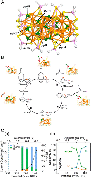 | ||
| Fig. 31 (A) Geometric structure of the Cu32H18(S2PH2)12. Color code: orange, Cu; green, hydride; yellow, S; purple, P; white, H on the dithiophosphate ligands. Different types of hydrides are indicated by the arrows. (B) (a–d) Overall mechanism of HCOOH formation from CO2 reduction on Cu32H18(S2PH2)12via the lattice-hydride channel. (C) (a) Average current densities (black circles) and cumulative Faraday efficiencies and (b) product selectivity for H2, HCOOH, and CO obtained at different overpotentials. Panels (A)–(C) are reproduced with permission from ref. 325. Copyright 2017 American Chemical Society. | ||
In 2020, Robinson et al. reported the CRR activity of Cu13(MBO)12 (MBO = 2-mercaptobenzoxazole), which is composed of 13 Cu atoms and 12 MBO ligands.326 They reported that the valence of Cu atoms in Cu13(MBO)12 has an oxidation state between 0 and +1 and is highly resistant to oxidation. Cu13(MBO)12 produced 72.6% H2, 13.2% CO, and 0.25% CH4 as the main product at −1.04 V vs. RHE in CRR.
In 2022, Wang and Zang et al. evaluated the electrocatalytic activity of CRRs using three types of Cu8 NCs with different cubic and tetrahedral core structures.273 For Cu8(H)(L1)6PF6 with a cubic core structure and Cu8(StBu)4(L1)4 and Cu8(StBu)4(L2)4 with tetrahedral core structures, Cu8(StBu)4(L1)4 showed the highest catalytic activity, selectivity, and stability for the conversion of CO2 to HCOOH, showing an FEHCOOH of 92% at −1.0 V vs. RHE. From DFT calculations, the difference in CRR catalytic activity was attributed to the cubic form of Cu8(H)(L1)6PF6 having an active site favorable for the competitive reaction HER, whereas the tetrahedral form of Cu8(StBu)4(L1)4 had an active site favorable for the formation of *COOH in CO formation and *OOCH in formic acid formation. This suggested that highly active and highly selective CRR catalysts can be created by controlling the core structure and surface morphology of Cu NCs.
Doping and ligand effects in Cu NCs have also been reported. In 2022, Ma, Song, and Wang et al. evaluated the CRR activity using [M@Cu24H22(PR3)12]+ (M = Au or Cu; PR3 = PPh3 or P(p-FPh)3),275 which are protected by two phosphine ligands, as electrocatalysts.327 [M@Cu24H22(PR3)12]+ has a M@Cu12 (M = Au or Cu) icosahedral kernel core, surrounded by a shell of four Cu3P3 units. The M@Cu12 kernel is bonded to the Cu(I) shell via a Cu–Cu metal bond. These [M@Cu24H22(PR3)12]+ were loaded on multi-layered CNTs at 50 wt% to make CRR catalysts. From gas chromatography and 1H-NMR spectroscopy, only CO, H2, and HCOOH were observed as products. As shown in Fig. 32(a), [Au@Cu24H22(PPh3)12]+ exhibited the highest FECO of 45.6% at −1.0 V vs. RHE, whereas [Cu25H22(PPh3)12]+ mainly produced H2 (FEH2 > 80%). Differences in the results are due to Au doping, indicating that a single atom of Au doping can significantly change the selectivity of the CRRs. Moreover, the use of a different ligand, p-FPPh3, decreased CO selectivity and increased HCOOH selectivity. As a result, for [Au@Cu24H22(P(p-FPh)3)12]+ and [Cu25H22(P(p-FPh)3)12]+, FEHCOOH was 30.6% and 20.3%, respectively, more than three times higher than that of [M@Cu24H22(PPh3)12]+ (Fig. 32(a)). When P(p-FPh)3 was used as the ligand, similarly to PPh3, the Au doping of one atom tended to increase the selectivity of C1 products and decrease the selectivity of H2 (Fig. 32(b)). The FECO+HCOOH values at −0.8 V vs. RHE were 55.9%, 14.8%, 40.5%, and 20.3% for [Au@Cu24H22(PPh3)12]+, [Cu25H22(PPh3)12]+, [Au@Cu24H22(P(p-FPh)3)12]+ and [Cu25H22(P(p-FPh)3)12]+, respectively (Fig. 32(b)). These results indicate that the metal core has a significant effect on the selectivity of the two competing reactions (CRR and HER) and that the type of ligand changes the selectivity of the C1 product of CRR (HCOOH and CO). The change in selectivity may be due to the lower density of electron clouds for Cu atoms on the NC surface, caused by the electrophilic Au doping and the electrophilic ligand, P(p-FPh)3. This report revealed that Au doping can reduce the selectivity of the HER in electrochemical CRRs of Cu NCs containing hydride, and the use of electrophilic ligands not only enhances the stability of Cu NCs but also promotes the selectivity of HCOOH in the CRR. Such high selectivity for HCOOH was also predicted from DFT calculations using [Cu25H22(PH3)12]Cl.328 Furthermore, [Cu26(CF3CO2)8(CH3O)2(C![[triple bond, length as m-dash]](https://www.rsc.org/images/entities/char_e002.gif) CtBu)4(DPPE)3H11]+ is also reported to be a catalyst exhibiting high CO selectivity.329 Regarding the templated Cu NCs, [Cu4Ti9O9(BC)18(OiPr)3(C
CtBu)4(DPPE)3H11]+ is also reported to be a catalyst exhibiting high CO selectivity.329 Regarding the templated Cu NCs, [Cu4Ti9O9(BC)18(OiPr)3(C![[triple bond, length as m-dash]](https://www.rsc.org/images/entities/char_e002.gif) CtBu)(CH3CN)] (BC = benzoic acid) exhibited high selectivity and good catalytic activity for the electrocatalytic reduction of CO2 to C2H4 at 400 mA cm−2 (FEC2H4: 47.6 ± 3.4%).330
CtBu)(CH3CN)] (BC = benzoic acid) exhibited high selectivity and good catalytic activity for the electrocatalytic reduction of CO2 to C2H4 at 400 mA cm−2 (FEC2H4: 47.6 ± 3.4%).330
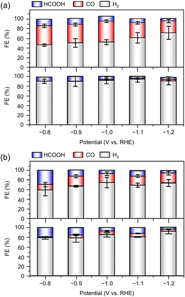 | ||
| Fig. 32 Electrocatalytic performance of the four M@Cu24 (M = Au/Cu) NCs in CRR. (a) [M@Cu24H22(PPh3)12]+ (M = Au or Cu) and (b) [M@Cu24H22(P(p-FPh)3)12]+ (M = Au or Cu). The error bars represent the standard deviation of three tests at the same test potential. (A) and (B) are reproduced with permission from ref. 327. Copyright 2022 Springer Nature. | ||
From these reports, the CRR products of Cu NCs are often not only CO but also HCOOH, CH4, and C2 compounds.
4. Conclusion
The conversion of CO2 into useful compounds by electrochemical CRR is a promising strategy for achieving carbon neutrality by directly reducing CO2 emissions. Unlike suppressing CO2 emissions, electrochemical catalysis directly supports the sustainable development of an energy-independent society that is considerate of the global environment. Against this background, research on electrochemical CRR has been actively studied by various groups in recent years. However, to date, most studies have focused on metal NPs with particle sizes larger than 2–3 nm. Conversely, the number of reported cases of electrocatalysts using ∼1 nm metal NCs has been increasing since the 2010s and expanded rapidly around 2020 (Fig. 33). The previous studies summarized in this review have revealed the following insights into electrochemical CRRs using metal NCs (Fig. 34).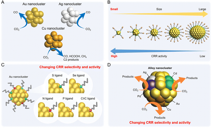 | ||
| Fig. 34 Schematic of the relationship between (A) metal species, (B) size, (C) ligands, (D) alloying effect for electrocatalytic CRR performance using metal NCs. | ||
(1) Au, Ag, and Cu NCs can be synthesized as controlling the chemical composition and geometric electronic structure with atomic precision. In particular, there are many synthesis reports for Au and Ag NCs, and examples of synthesis for Cu NCs have also been reported. These can be synthesized with changing the size, geometric structure, type of ligand, and charge state (Fig. 1B).
(2) Au, Ag, and Cu NCs can be easily synthesized by a liquid-phase reduction method (Fig. 33A) in which a reducing agent is added to a solution containing metal salts and ligands.32,35,37,38,40,41 Furthermore, metal NCs with different compositions and structures can be synthesized by the ligand exchange method (Fig. 33B) using metal NCs as precursors.39,42,331 Moreover, these alloy NCs can also be obtained by metal exchange method6 (Fig. 33C) or antigalvanic reaction8 (Fig. 33D) using specific metal NCs as precursors. It is also possible to add metal atoms (Fig. 33E) by reacting with metal salts under conditions different from metal exchange.332 There are also reports of molecular surgery (Fig. 33F), which removes some surface Au atoms while maintaining the core structure of the precursor metal NCs.333 In these examples, it has become possible to synthesize metal NCs using various methods. However, most of the reported examples using various synthesis methods are limited to Au NCs.
(3) In Au and Ag NCs, the primary CRR product is CO in many cases, and some have high selectivity for the HER, which is a competitive reaction (Fig. 34A).
(4) In Cu NCs and Cu-doped Au and Ag NCs, the CRR products are often not only CO but also HCOOH, CH4, and C2 compounds (Fig. 34A).
(5) Decreases in the size of Aun(SR)m may promote increased CRR activity and selectivity (Fig. 34B). This is also the case with other electrocatalytic reaction systems such as HER, OER, and ORR.120
(6) Even in metal NCs with the same chemical composition, differences in geometric structure can cause changes in CRR activity.
(7) The CRR selectivity changes significantly depending on the type of protective ligand bound to the surface of the metal NCs (Fig. 34C).
(8) Exposure of metal atoms on metal NCs due to desorption of protective ligands may promote increased CRR activity and selectivity. DFT calculations suggest that CRR activity is associated with the desorption of organic ligands in many cases, and such desorption is presumably caused by electrochemical pretreatment or adsorption process on carbon supports.
(9) Doping of Aun(SR)m using metal species, such as Ag and Pd, improves CRR selectivity in many cases (Fig. 34D). Such changes in activity and selectivity also depend on the doping position.
(10) Pd and Cd doping in Au25(SR)18 promote enhanced CRR activity, and Pt doping promotes enhanced HER activity in many cases (Fig. 34D).
(11) When the main CRR product is CO, the *COOH formation is the rate-determining step in many cases, and the lowering of the energy barrier is the factor of high activation.
5. Outlook
As summarized in section 4, further development of synthetic methods and evaluation of the activity of noble metal NCs may lead to highly active electrocatalysts that have not been discovered for NPs. In addition, the following initiatives are expected to be implemented in the future.(1) Highly active and selective synthesis of useful compounds
In many reports, the main CRR products in Au, Ag, and Cu NCs is CO. CO can be used as a raw material for synthesis gas (mixture of CO and H2), etc., but it may not economically be worth considering the cost of CO2 capture because of the price competition with CO made from fossil fuels.75 Therefore, the development of NCs catalysts that can synthesize other useful compounds (C1 compounds such as HCOOH and CH3OH or C2–C3 compounds) is required.75 Although some metal NCs have been reported that can be synthesized useful compounds from CO2,245,254,273,325 their efficiency and selectivity is still low, and the creation of NCs catalysts with higher activity and selectivity is required. In particular, the bond distance of atoms in Metal NCs is considered to have a great effect on the making C–C coupling to obtain C2–C3 compounds. The effect of the geometric/electronic structure of Metal NCs on the selectivity of CRR products will be further clarified, and it is expected that Metal NCs with highly selective CRR catalyst will be designed and created to obtain useful compounds.
(2) Increased durability
Without proper treatment, ligand-protected metal NCs easily agglomerate due to ligand elimination.106 Electrochemical reduction has also been reported to desorb ligands from metal NCs, but the detailed mechanism remains unclear.305 In addition, at present, in many cases, metal NCs are supported on a carbon black as a support having a high specific surface area, which prevents the aggregation of metal NCs even if some of the ligands are eliminated. Therefore, it has been reported that some metal NCs with stable structures have relatively high stability.188,202,245,255,263,295,314 However, in order to improve the durability of less stable metal NCs, it is necessary to protect them by ligands with strong bonds, load metal NCs on supports with high specific surface area and high conductivity.
(3) Use of various non-precious metal nanoclusters
Precious metals are expensive and rare, and the discovery of base metals that can be substituted in metal NCs is important because it directly leads to lower costs. The use of metal NCs composed of inexpensive metal elements, such as manganese (Mn), Ni, Fe, cobalt (Co), and Cu, is expected to develop further. It has been suggested that these metal NCs may also exhibit high CRR activity due to their different electronic states from the bulk.334–336 Especially in CRRs, Cu is expected to be a unique catalyst for obtaining various organic compounds. However, reports of Cu NCs applied in CRRs are limited. In the future, the development of highly stable Cu NCs may lead to the practical application of CO2 recycling using electrocatalytic CRRs.
(4) Control of geometric structure of loaded nanoclusters
The true geometric/electronic structure of metal NCs after adsorption on carbon supports and after ligand desorption remains unclear. Therefore, further advancing the structural analysis/analytical techniques for loaded NCs and elucidating the desorption mechanism of ligands are necessary. If the structure of the loaded NCs is clarified, theoretical calculations using this information may provide an understanding of the reaction mechanism and reveal the key factors for high activity.
(5) Development of support and binder for metal nanoclusters
Electrocatalytic activity is also greatly affected by the support and the ionomer (such as Nafion), which functions as the binder. In the previous reports, there are few examples examining these dependencies for metal NCs. The geometric/electronic structure of metal NCs is significantly different from that of metal NPs, and support interactions and stability are also expected to be different from those of metal NPs. Particularly, supports and binders with higher specific surface area and stronger binding to metal NCs should be developed for electrocatalytic applications. For example, metals NCs such as Au, Ag, and Cu have strong bonds with nonmetallic elements such as S, P (phosphorus), and N (nitrogen).305 Therefore, it is expected that the stability can be improved by using a support and a binder to which these elements are included.
(6) Accurate analysis of liquid-phase CO 2 reduction reaction products
The improper evaluation of the liquid-phase components may lead to inaccurate assessments of the selectivity of the actual CRR products. For example, HCOOH produced by CRR is not identified by only analysis of gas-phase components. Furthermore, it might be present in the electrolytic solution as formate (HCOO−), and appropriate quantitative analysis methods are needed. Therefore, standardized analytical methods must be developed.
(7) Verification of the products derived from CO 2
Many studies have not demonstrated that the CRR products are derived explicitly from the CO2 that is being introduced. Therefore, it is necessary to show that the products are not derived from ligands desorbed from metal NCs or carbon supports (e.g., evaluation using the CO2 isotope).
(8) Activity evaluation according to standards
The selectivity of CRR products varies greatly depending on the catalytic system, such as the structure of the CRR reaction cells (e.g., two-chamber cell or flow cell). Thus, standardized evaluation methods (using a standard electrolyte, Nafion membrane, counter electrode, carbon support type, etc.) are necessary for sharing and comparing data among researchers.
We hope that these issues will be overcome in the future and that efficient electrocatalysts can be developed for practical applications, which can potentially solve multiple energy and environmental problems.
Conflicts of interest
There are no conflicts to declare.Acknowledgements
This work was supported by the Japan Society for the Promotion of Science (JSPS) KAKENHI (grant number 20H02698, 20H02552, 23H00289), Scientific Research on Innovative Areas “Innovations for Light-Energy Conversion” (grant number 18H05178 and 20H05115), Scientific Research on Innovative Areas “Hydrogenomics” (grant number 21H00027), and JST Adaptable and Seamless Technology transfer Program through Target-driven R&D (A-STEP; grant number JPMJTM20MS). Funding from Nissanken, the Yashima Environment Technology Foundation, the Yazaki Memorial Foundation for Science and Technology, the MIKIYA Science and Technology Foundation, the Kao Foundation for Arts and Sciences, the Sasakawa Scientific Research Grant from the Japan Science Society, Advanced Technology Institute Research Grants 2022, TEPCO Memorial Foundation Research Grant (Basic Research), Takahashi Industrial and Economic Research Foundation and the Kumagai Foundation for Science and Technology are gratefully acknowledged.References
- S. Hossain, D. Hirayama, A. Ikeda, M. Ishimi, S. Funaki, A. Samanta, T. Kawawaki and Y. Negishi, Aggregate, 2023, 4, e255 CrossRef CAS.
- T. Higaki, Q. Li, M. Zhou, S. Zhao, Y. Li, S. Li and R. Jin, Acc. Chem. Res., 2018, 51, 2764 CrossRef CAS.
- S. Takano, S. Hasegawa, M. Suyama and T. Tsukuda, Acc. Chem. Res., 2018, 51, 3074 CrossRef CAS PubMed.
- N. A. Sakthivel and A. Dass, Acc. Chem. Res., 2018, 51, 1774 CrossRef CAS.
- B. Nieto-Ortega and T. Bürgi, Acc. Chem. Res., 2018, 51, 2811 CrossRef CAS PubMed.
- S. Wang, Q. Li, X. Kang and M. Zhu, Acc. Chem. Res., 2018, 51, 2784 CrossRef CAS PubMed.
- S. Hossain, Y. Niihori, L. V. Nair, B. Kumar, W. Kurashige and Y. Negishi, Acc. Chem. Res., 2018, 51, 3114 CrossRef CAS PubMed.
- Z. Gan, N. Xia and Z. Wu, Acc. Chem. Res., 2018, 51, 2774 CrossRef CAS.
- J. Yan, B. K. Teo and N. Zheng, Acc. Chem. Res., 2018, 51, 3084 CrossRef CAS.
- Q. Tang, G. Hu, V. Fung and D.-e. Jiang, Acc. Chem. Res., 2018, 51, 2793 CrossRef CAS PubMed.
- C. M. Aikens, Acc. Chem. Res., 2018, 51, 3065 CrossRef CAS PubMed.
- Y. Cao, T. Chen, Q. Yao and J. Xie, Acc. Chem. Res., 2021, 54, 4142 CrossRef CAS.
- M. Hesari and Z. Ding, Acc. Chem. Res., 2017, 50, 218 CrossRef CAS PubMed.
- J. F. Parker, C. A. Fields-Zinna and R. W. Murray, Acc. Chem. Res., 2010, 43, 1289 CrossRef CAS PubMed.
- K. Kwak and D. Lee, Acc. Chem. Res., 2019, 52, 12 CrossRef CAS PubMed.
- P. Chakraborty, A. Nag, A. Chakraborty and T. Pradeep, Acc. Chem. Res., 2019, 52, 2 CrossRef CAS PubMed.
- M. Agrachev, M. Ruzzi, A. Venzo and F. Maran, Acc. Chem. Res., 2019, 52, 44 CrossRef CAS PubMed.
- S. H. Yau, O. Varnavski and T. Goodson III, Acc. Chem. Res., 2013, 46, 1506 CrossRef CAS PubMed.
- A. Ghosh, O. F. Mohammed and O. M. Bakr, Acc. Chem. Res., 2018, 51, 3094 CrossRef CAS.
- T. Zhao, P. J. Herbert, H. Zheng and K. L. Knappenberger Jr., Acc. Chem. Res., 2018, 51, 1433 CrossRef CAS PubMed.
- Y. Pei, P. Wang, Z. Ma and L. Xiong, Acc. Chem. Res., 2019, 52, 23 CrossRef CAS PubMed.
- W. W. Xu, X. C. Zeng and Y. Gao, Acc. Chem. Res., 2018, 51, 2739 CrossRef CAS.
- Z. Lei, X.-K. Wan, S.-F. Yuan, Z.-J. Guan and Q.-M. Wang, Acc. Chem. Res., 2018, 51, 2465 CrossRef CAS PubMed.
- A. W. Cook and T. W. Hayton, Acc. Chem. Res., 2018, 51, 2456 CrossRef CAS PubMed.
- Q.-F. Zhang, X. Chen and L.-S. Wang, Acc. Chem. Res., 2018, 51, 2159 CrossRef CAS PubMed.
- B. Bhattarai, Y. Zaker, A. Atnagulov, B. Yoon, U. Landman and T. P. Bigioni, Acc. Chem. Res., 2018, 51, 3104 CrossRef CAS PubMed.
- S. Sharma, K. K. Chakrahari, J.-Y. Saillard and C. W. Liu, Acc. Chem. Res., 2018, 51, 2475 CrossRef CAS PubMed.
- R. L. Whetten, H.-C. Weissker, J. J. Pelayo, S. M. Mullins, X. López-Lozano and I. L. Garzón, Acc. Chem. Res., 2019, 52, 34 CrossRef CAS PubMed.
- Q. Yao, T. Chen, X. Yuan and J. Xie, Acc. Chem. Res., 2018, 51, 1338 CrossRef CAS PubMed.
- R. Jin, H. Qian, Z. Wu, Y. Zhu, M. Zhu, A. Mohanty and N. Garg, J. Phys. Chem. Lett., 2010, 1, 2903 CrossRef CAS.
- S. Jin, S. Wang and M. Zhu, Chem. – Asian J., 2019, 14, 3222 CrossRef CAS.
- Y. Jia and Z. Luo, Coord. Chem. Rev., 2019, 400, 213053 CrossRef CAS.
- S. Yamazoe and T. Tsukuda, Bull. Chem. Soc. Jpn., 2019, 92, 193 CrossRef CAS.
- E. Fernández and M. Boronat, J. Phys.: Condens. Matter, 2019, 31, 013002 CrossRef.
- B. Yin and Z. Luo, Coord. Chem. Rev., 2021, 429, 213643 CrossRef CAS.
- Y. Negishi, S. Hashimoto, A. Ebina, K. Hamada, S. Hossain and T. Kawawaki, Nanoscale, 2020, 12, 8017 RSC.
- T. Kawawaki, Y. Imai, D. Suzuki, S. Kato, I. Kobayashi, T. Suzuki, R. Kaneko, S. Hossain and Y. Negishi, Chem. – Eur. J., 2020, 26, 16150 CrossRef CAS PubMed.
- X. Kang, Y. Li, M. Zhu and R. Jin, Chem. Soc. Rev., 2020, 49, 6443 RSC.
- Y. Wang and T. Bürgi, Nanoscale Adv., 2021, 3, 2710 RSC.
- X. Kang and M. Zhu, Chem. Mater., 2021, 33, 39 CrossRef CAS.
- Y. Niihori, S. Miyajima, A. Ikeda, T. Kosaka and Y. Negishi, Small Sci., 2023, 3, 2300024 CrossRef CAS.
- X. Kang and M. Zhu, Chem. Mater., 2019, 31, 9939 CrossRef CAS.
- K. Sahoo and I. Chakraborty, Nanoscale, 2023, 15, 3120 RSC.
- Y.-e. Shi, J. Ma, A. Feng, Z. Wang and A. L. Rogach, Aggregate, 2021, 2, e112 CrossRef CAS.
- H. Ma, J. Wang and X.-D. Zhang, Coord. Chem. Rev., 2021, 448, 214184 CrossRef CAS.
- M.-M. Zhang, K. Li and S.-Q. Zang, Adv. Opt. Mater., 2020, 8, 1902152 CrossRef CAS.
- X. Kang and M. Zhu, Chem. Soc. Rev., 2019, 48, 2422 RSC.
- Y. Shichibu and K. Konishi, ChemNanoMat, 2022, 8, e202200194 CrossRef CAS.
- J.-H. Huang, X.-Y. Dong, Y.-J. Wang and S.-Q. Zang, Coord. Chem. Rev., 2022, 470, 214729 CrossRef CAS.
- S. Hasegawa and T. Tsukuda, Bull. Chem. Soc. Jpn., 2021, 94, 1036 CrossRef CAS.
- T. Kawawaki, A. Ebina, Y. Hosokawa, S. Ozaki, D. Suzuki, S. Hossain and Y. Negishi, Small, 2021, 17, 2005328 CrossRef CAS PubMed.
- T. Kawawaki, Y. Kataoka, M. Hirata, Y. Iwamatsu, S. Hossain and Y. Negishi, Nanoscale Horiz., 2021, 6, 409 RSC.
- T. Imaoka and K. Yamamoto, Bull. Chem. Soc. Jpn., 2019, 92, 941 CrossRef CAS.
- C. Dong, Y. Li, D. Cheng, M. Zhang, J. Liu, Y.-G. Wang, D. Xiao and D. Ma, ACS Catal., 2020, 10, 11011 CrossRef CAS.
- Q. Zhu, X. Huang, Y. Zeng, K. Sun, L. Zhou, Y. Liu, L. Luo, S. Tian and X. Sun, Nanoscale Adv., 2021, 3, 6330 RSC.
- R. S. Dhayal, W. E. van Zyl and C. W. Liu, Dalton Trans., 2019, 48, 3531 RSC.
- D. Yang, J. Wang, Q. Wang, Z. Yuan, Y. Dai, C. Zhou, X. Wan, Q. Zhang and Y. Yang, ACS Nano, 2022, 16, 15681 CrossRef CAS PubMed.
- T. Kawawaki, N. Shimizu, Y. Mitomi, D. Yazaki, S. Hossain and Y. Negishi, Bull. Chem. Soc. Jpn., 2021, 94, 2853 CrossRef CAS.
- Y. Niihori, K. Yoshida, S. Hossain, W. Kurashige and Y. Negishi, Bull. Chem. Soc. Jpn., 2019, 92, 664 CrossRef CAS.
- T. Kawawaki, Y. Negishi and H. Kawasaki, Nanoscale Adv., 2020, 2, 17 RSC.
- Y. Xiao, Z. Wu, Q. Yao and J. Xie, Aggregate, 2021, 2, 114 CrossRef CAS.
- W. Kurashige, Y. Niihori, S. Sharma and Y. Negishi, Coord. Chem. Rev., 2016, 320–321, 238 CrossRef CAS.
- I. Chakraborty and T. Pradeep, Chem. Rev., 2017, 117, 8208 CrossRef CAS.
- R. Jin, C. Zeng, M. Zhou and Y. Chen, Chem. Rev., 2016, 116, 10346 CrossRef CAS PubMed.
- C. Cesari, J.-H. Shon, S. Zacchini and L. A. Berben, Chem. Soc. Rev., 2021, 50, 9503 RSC.
- M. Brust, M. Walker, D. Bethell, D. J. Schiffrin and R. Whyman, J. Chem. Soc., Chem. Commun., 1994, 801 RSC.
- R. S. Ingram, M. J. Hostetler, R. W. Murray, T. G. Schaaff, J. T. Khoury, R. L. Whetten, T. P. Bigioni, D. K. Guthrie and P. N. First, J. Am. Chem. Soc., 1997, 119, 9279 CrossRef CAS.
- T. G. Schaaff, M. N. Shafigullin, J. T. Khoury, I. Vezmar, R. L. Whetten, W. G. Cullen, P. N. First, C. Gutiérrez-Wing, J. Ascensio and M. J. Jose-Yacamán, J. Phys. Chem. B, 1997, 101, 7885 CrossRef CAS.
- R. L. Whetten, J. T. Khoury, M. M. Alvarez, S. Murthy, I. Vezmar, Z. L. Wang, P. W. Stephens, C. L. Cleveland, W. D. Luedtke and U. Landman, Adv. Mater., 1996, 8, 428 CrossRef CAS.
- Y. Negishi, Y. Takasugi, S. Sato, H. Yao, K. Kimura and T. Tsukuda, J. Am. Chem. Soc., 2004, 126, 6518 CrossRef CAS PubMed.
- Y. Negishi, K. Nobusada and T. Tsukuda, J. Am. Chem. Soc., 2005, 127, 5261 CrossRef CAS PubMed.
- Y. Negishi, Phys. Chem. Chem. Phys., 2022, 24, 7569 RSC.
- P. D. Jadzinsky, G. Calero, C. J. Ackerson, D. A. Bushnell and R. D. Kornberg, Science, 2007, 318, 430 CrossRef CAS.
- S. Manabe and R. T. Wetherald, J. Atmos. Sci., 1967, 24, 241 CrossRef CAS.
- S. Nitopi, E. Bertheussen, S. B. Scott, X. Liu, A. K. Engstfeld, S. Horch, B. Seger, I. E. L. Stephens, K. Chan, C. Hahn, J. K. Nørskov, T. F. Jaramillo and I. Chorkendorff, Chem. Rev., 2019, 119, 7610 CrossRef CAS.
- G. Wang, J. Chen, Y. Ding, P. Cai, L. Yi, Y. Li, C. Tu, Y. Hou, Z. Wen and L. Dai, Chem. Soc. Rev., 2021, 50, 4993 RSC.
- S. Rönsch, J. Schneider, S. Matthischke, M. Schlüter, M. Götz, J. Lefebvre, P. Prabhakaran and S. Bajohr, Fuel, 2016, 166, 276 CrossRef.
- P. Sabatier and J. B. Senderens, C. R. Hebd. Seances Acad. Sci., 1902, 134, 689 Search PubMed.
- R. P. Underwood and C. O. Bennett, J. Catal., 1984, 86, 245 CrossRef CAS.
- Y. Liu, Y. Li, Y. Chen, T. Qu, C. Shu, X. Yang, H. Zhu, S. Guo, S. Zhao, T. Asefa and Y. Liu, J. Mater. Chem. A, 2020, 8, 8329 RSC.
- T. E. Teeter and P. Van Rysselberghe, J. Chem. Phys., 2004, 22, 759 CrossRef.
- Y. Hori, K. Kikuchi and S. Suzuki, Chem. Lett., 1985, 14, 1695 CrossRef.
- Y. Hori, K. Kikuchi, A. Murata and S. Suzuki, Chem. Lett., 1986, 15, 897 CrossRef.
- Y. Hori, A. Murata, R. Takahashi and S. Suzuki, J. Chem. Soc., Chem. Commun., 1988, 17 RSC.
- Y. Hori, H. Wakebe, T. Tsukamoto and O. Koga, Electrochim. Acta, 1994, 39, 1833 CrossRef CAS.
- Y. Hori, A. Murata and R. Takahashi, J. Chem. Soc., Faraday Trans. 1, 1989, 85, 2309 RSC.
- S. Jin, Z. Hao, K. Zhang, Z. Yan and J. Chen, Angew. Chem., Int. Ed., 2021, 60, 20627 CrossRef CAS PubMed.
- N. Han, P. Ding, L. He, Y. Li and Y. Li, Adv. Energy Mater., 2020, 10, 1902338 CrossRef CAS.
- L. Wang, W. Chen, D. Zhang, Y. Du, R. Amal, S. Qiao, J. Wu and Z. Yin, Chem. Soc. Rev., 2019, 48, 5310 RSC.
- Y. T. Guntern, V. Okatenko, J. Pankhurst, S. B. Varandili, P. Iyengar, C. Koolen, D. Stoian, J. Vavra and R. Buonsanti, ACS Catal., 2021, 11, 1248 CrossRef CAS.
- J. A. Trindell, Z. Duan, G. Henkelman and R. M. Crooks, Chem. Rev., 2020, 120, 814 CrossRef CAS.
- M. K. Birhanu, M.-C. Tsai, A. W. Kahsay, C.-T. Chen, T. S. Zeleke, K. B. Ibrahim, C.-J. Huang, W.-N. Su and B.-J. Hwang, Adv. Mater. Interfaces, 2018, 5, 1800919 CrossRef.
- Y. Cheng, S. Yang, S. P. Jiang and S. Wang, Small Methods, 2019, 3, 1800440 CrossRef.
- Z.-X. Wei, Y.-T. Zhu, J.-Y. Liu, Z.-C. Zhang, W.-P. Hu, H. Xu, Y.-Z. Feng and J.-M. Ma, Rare Met., 2021, 40, 767 CrossRef CAS.
- Q. Zhang and J. Guan, Adv. Funct. Mater., 2020, 30, 2000768 CrossRef CAS.
- Y.-S. Wei, M. Zhang, R. Zou and Q. Xu, Chem. Rev., 2020, 120, 12089 CrossRef CAS.
- Y. Wang, H. Su, Y. He, L. Li, S. Zhu, H. Shen, P. Xie, X. Fu, G. Zhou, C. Feng, D. Zhao, F. Xiao, X. Zhu, Y. Zeng, M. Shao, S. Chen, G. Wu, J. Zeng and C. Wang, Chem. Rev., 2020, 120, 12217 CrossRef CAS.
- J.-M. Saveant, ChemElectroChem, 2016, 3, 1967 CrossRef CAS.
- L. Sun, V. Reddu, A. C. Fisher and X. Wang, Energy Environ. Sci., 2020, 13, 374 RSC.
- A. Wagner, C. D. Sahm and E. Reisner, Nat. Catal., 2020, 3, 775 CrossRef CAS.
- Y. Du, H. Sheng, D. Astruc and M. Zhu, Chem. Rev., 2020, 120, 526 CrossRef CAS PubMed.
- T. Kawawaki, Y. Kataoka, S. Ozaki, M. Kawachi, M. Hirata and Y. Negishi, Chem. Commun., 2021, 57, 417 RSC.
- T. Kawawaki, Y. Mori, K. Wakamatsu, S. Ozaki, M. Kawachi, S. Hossain and Y. Negishi, J. Mater. Chem. A, 2020, 8, 16081 RSC.
- D. Yazaki, T. Kawawaki, D. Hirayama, M. Kawachi, K. Kato, S. Oguchi, Y. Yamaguchi, S. Kikkawa, Y. Ueki, S. Hossain, D. J. Osborn, F. Ozaki, S. Tanaka, J. Yoshinobu, G. F. Metha, S. Yamazoe, A. Kudo, A. Yamakata and Y. Negishi, Small, 2023, 2208287 CrossRef CAS PubMed.
- T. Kawawaki, M. Kawachi, D. Yazaki, Y. Akinaga, D. Hirayama and Y. Negishi, Nanomaterials, 2022, 12, 344 CrossRef CAS.
- T. Kawawaki, Y. Kataoka, M. Hirata, Y. Akinaga, R. Takahata, K. Wakamatsu, Y. Fujiki, M. Kataoka, S. Kikkawa, A. S. Alotabi, S. Hossain, D. J. Osborn, T. Teranishi, G. G. Andersson, G. F. Metha, S. Yamazoe and Y. Negishi, Angew. Chem., Int. Ed., 2021, 60, 21340 CrossRef CAS.
- Y. H. Li, J. Xing, Z. J. Chen, Z. Li, F. Tian, L. R. Zheng, H. F. Wang, P. Hu, H. J. Zhao and H. G. Yang, Nat. Commun., 2013, 4, 2500 CrossRef.
- Q. Wu, S. Xiong, P. Shen, S. Zhao, Y. Li, D. Su and A. Orlov, Catal. Sci. Technol., 2015, 5, 2059 RSC.
- X. L. Du, X. L. Wang, Y. H. Li, Y. L. Wang, J. J. Zhao, L. J. Fang, L. R. Zheng, H. Tong and H. G. Yang, Chem. Commun., 2017, 53, 9402 RSC.
- C. Wang, P. Lv, D. Xue, Y. Cai, X. Yan, L. Xu, J. Fang and Y. Yang, ACS Sustainable Chem. Eng., 2018, 6, 8447 CrossRef CAS.
- L. Tian, Y. Luo, K. Chu, D. Wu, J. Shi and Z. Liang, Chem. Commun., 2019, 55, 12976 RSC.
- C. M. Pelicano, M. Saruyama, R. Takahata, R. Sato, Y. Kitahama, H. Matsuzaki, T. Yamada, T. Hisatomi, K. Domen and T. Teranishi, Adv. Funct. Mater., 2022, 32, 2202987 CrossRef CAS.
- L. Qin, G. Ma, L. Wang and Z. Tang, J. Energy Chem., 2021, 57, 359 CrossRef CAS.
- Y. Sun, X. Cai, W. Hu, X. Liu and Y. Zhu, Sci. China: Chem., 2021, 64, 1065 CrossRef CAS.
- M. H. Naveen, R. Khan and J. H. Bang, Chem. Mater., 2021, 33, 7595 CrossRef CAS.
- T. Kawawaki and Y. Negishi, Nanomaterials, 2020, 10, 238 CrossRef CAS.
- A. Dass, D. Lee and F. Maran, ChemElectroChem, 2016, 3, 1191 CrossRef CAS.
- K. Kwak, W. Choi, Q. Tang, M. Kim, Y. Lee, D.-e. Jiang and D. Lee, Nat. Commun., 2017, 8, 14723 CrossRef.
- G. Hu, Q. Tang, D. Lee, Z. Wu and D.-e. Jiang, Chem. Mater., 2017, 29, 4840 CrossRef CAS.
- B. Kumar, T. Kawawaki, N. Shimizu, Y. Imai, D. Suzuki, S. Hossain, L. V. Nair and Y. Negishi, Nanoscale, 2020, 12, 9969 RSC.
- D. Eguchi, M. Sakamoto and T. Teranishi, Chem. Sci., 2018, 9, 261 RSC.
- Y. Du, J. Xiang, K. Ni, Y. Yun, G. Sun, X. Yuan, H. Sheng, Y. Zhu and M. Zhu, Inorg. Chem. Front., 2018, 5, 2948 RSC.
- S. Zhao, R. Jin, Y. Song, H. Zhang, S. D. House, J. C. Yang and R. Jin, Small, 2017, 13, 1701519 CrossRef.
- X. Zhao, P. Gao, Y. Yan, X. Li, Y. Xing, H. Li, Z. Peng, J. Yang and J. Zeng, J. Mater. Chem. A, 2017, 5, 20202 RSC.
- S. Zhao, R. Jin, H. Abroshan, C. Zeng, H. Zhang, S. D. House, E. Gottlieb, H. J. Kim, J. C. Yang and R. Jin, J. Am. Chem. Soc., 2017, 139, 1077 CrossRef CAS PubMed.
- S. Funaki, T. Kawawaki, T. Okada, K. Takemae, S. Hossain, Y. Niihori, T. Naito, M. Takagi, T. Shimazaki, S. Kikkawa, S. Yamazoe, M. Tachikawa and Y. Negishi, Nanoscale, 2023, 15, 5201 RSC.
- W. Chen and S. Chen, Angew. Chem., Int. Ed., 2009, 48, 4386 CrossRef CAS.
- T. Kawawaki, N. Shimizu, K. Funai, Y. Mitomi, S. Hossain, S. Kikkawa, D. J. Osborn, S. Yamazoe, G. F. Metha and Y. Negishi, Nanoscale, 2021, 13, 14679 RSC.
- T. Kawawaki, Y. Mitomi, N. Nishi, R. Kurosaki, K. Oiwa, T. Tanaka, H. Hirase, S. Miyajima, Y. Niihori, D. J. Osborn, T. Koitaya, G. F. Metha, T. Yokoyama, K. Iida and Y. Negishi, Nanoscale, 2023, 15, 7272 RSC.
- T. Imaoka, H. Kitazawa, W.-J. Chun, S. Omura, K. Albrecht and K. Yamamoto, J. Am. Chem. Soc., 2013, 135, 13089 CrossRef CAS PubMed.
- H. Tsunoyama, A. Ohnuma, K. Takahashi, A. Velloth, M. Ehara, N. Ichikuni, M. Tabuchi and A. Nakajima, Chem. Commun., 2019, 55, 12603 RSC.
- B. Garlyyev, K. Kratzl, M. Rück, J. Michalička, J. Fichtner, J. M. Macak, T. Kratky, S. Günther, M. Cokoja, A. S. Bandarenka, A. Gagliardi and R. A. Fischer, Angew. Chem., Int. Ed., 2019, 58, 9596 CrossRef CAS PubMed.
- H. Yin, H. Tang, D. Wang, Y. Gao and Z. Tang, ACS Nano, 2012, 6, 8288 CrossRef CAS PubMed.
- Y. Lu, Y. Jiang, X. Gao and W. Chen, Chem. Commun., 2014, 50, 8464 RSC.
- M. Zhou, C. Zeng, Y. Chen, S. Zhao, M. Y. Sfeir, M. Zhu and R. Jin, Nat. Commun., 2016, 7, 13240 CrossRef CAS PubMed.
- Y. Lu, C. Zhang, X. Li, A. R. Frojd, W. Xing, A. Z. Clayborne and W. Chen, Nano Energy, 2018, 50, 316 CrossRef CAS.
- Z. Zhuang and W. Chen, J. Colloid Interface Sci., 2019, 538, 699 CrossRef CAS PubMed.
- G. Ma, L. Qin, Y. Liu, H. Fan, L. Qiao, C. Yu and Z. Tang, Surf. Interfaces, 2023, 36, 102555 CrossRef CAS.
- F. Lü, H. Bao, Y. Mi, Y. Liu, J. Sun, X. Peng, Y. Qiu, L. Zhuo, X. Liu and J. Luo, Sustainable Energy Fuels, 2020, 4, 1012 RSC.
- Q. Guo, T. Lan, Z. Su, F. Zheng and W. Chen, Mater. Rep.: Energy, 2023, 3, 100172 CAS.
- L. Chen, L. Wang, Q. Shen, Y. Liu and Z. Tang, Mater. Chem. Front., 2023, 7, 1482 RSC.
- D. Alfonso, Catalysts, 2022, 12, 505 CrossRef CAS.
- A. V. Nagarajan, D. J. Loevlie, M. J. Cowan and G. Mpourmpakis, Curr. Opin. Chem. Eng., 2022, 36, 100784 CrossRef.
- H. Yan, H. Xiang, J. Liu, R. Cheng, Y. Ye, Y. Han and C. Yao, Small, 2022, 18, 2200812 CrossRef CAS PubMed.
- D. Yang, Y. Sun, X. Cai, W. Hu, Y. Dai, Y. Zhu and Y. Yang, CCS Chem., 2021, 4, 66 CrossRef.
- C. Li, O. J. H. Chai, Q. Yao, Z. Liu, L. Wang, H. Wang and J. Xie, Mater. Horiz., 2021, 8, 1657 RSC.
- W. Lai, Z. Ma, J. Zhang, Y. Yuan, Y. Qiao and H. Huang, Adv. Funct. Mater., 2022, 32, 2111193 CrossRef CAS.
- Z.-J. Guan, J.-J. Li, F. Hu and Q.-M. Wang, Angew. Chem., Int. Ed., 2022, 61, e202209725 CrossRef CAS PubMed.
- S. Li, W. Tian and Y. Liu, Nanoscale, 2021, 13, 16847 RSC.
- X. Cai, G. Li, W. Hu and Y. Zhu, ACS Catal., 2022, 12, 10638 CrossRef CAS.
- R. L. Donkers, D. Lee and R. W. Murray, Langmuir, 2004, 20, 1945 CrossRef CAS.
- T. G. Schaaff, G. Knight, M. N. Shafigullin, R. F. Borkman and R. L. Whetten, J. Phys. Chem. B, 1998, 102, 10643 CrossRef CAS.
- X. Kang, H. Chong and M. Zhu, Nanoscale, 2018, 10, 10758 RSC.
- M. Zhu, E. Lanni, N. Garg, M. E. Bier and R. Jin, J. Am. Chem. Soc., 2008, 130, 1138 CrossRef CAS PubMed.
- Z. Wu, J. Suhan and R. Jin, J. Mater. Chem., 2009, 19, 622 RSC.
- M. Zhu, W. T. Eckenhoff, T. Pintauer and R. Jin, J. Phys. Chem. C, 2008, 112, 14221 CrossRef CAS.
- M. Zhu, C. M. Aikens, M. P. Hendrich, R. Gupta, H. Qian, G. C. Schatz and R. Jin, J. Am. Chem. Soc., 2009, 131, 2490 CrossRef CAS PubMed.
- M. Zhu, C. M. Aikens, F. J. Hollander, G. C. Schatz and R. Jin, J. Am. Chem. Soc., 2008, 130, 5883 CrossRef CAS.
- M. W. Heaven, A. Dass, P. S. White, K. M. Holt and R. W. Murray, J. Am. Chem. Soc., 2008, 130, 3754 CrossRef CAS PubMed.
- S. Antonello, N. V. Perera, M. Ruzzi, J. A. Gascón and F. Maran, J. Am. Chem. Soc., 2013, 135, 15585 CrossRef CAS PubMed.
- A. Venzo, S. Antonello, J. A. Gascón, I. Guryanov, R. D. Leapman, N. V. Perera, A. Sousa, M. Zamuner, A. Zanella and F. Maran, Anal. Chem., 2011, 83, 6355 CrossRef CAS.
- G. Li, H. Abroshan, C. Liu, S. Zhuo, Z. Li, Y. Xie, H. J. Kim, N. L. Rosi and R. Jin, ACS Nano, 2016, 10, 7998 CrossRef CAS PubMed.
- D.-e. Jiang and S. Dai, Inorg. Chem., 2009, 48, 2720 CrossRef CAS.
- C. Kumara, C. M. Aikens and A. Dass, J. Phys. Chem. Lett., 2014, 5, 461 CrossRef CAS.
- R. Jin, S. Zhao, C. Liu, M. Zhou, G. Panapitiya, Y. Xing, N. L. Rosi, J. P. Lewis and R. Jin, Nanoscale, 2017, 9, 19183 RSC.
- Y. Negishi, T. Iwai and M. Ide, Chem. Commun., 2010, 46, 4713 RSC.
- J.-P. Choi, C. A. Fields-Zinna, R. L. Stiles, R. Balasubramanian, A. D. Douglas, M. C. Crowe and R. W. Murray, J. Phys. Chem. C, 2010, 114, 15890 CrossRef CAS.
- W. Kurashige, K. Munakata, K. Nobusada and Y. Negishi, Chem. Commun., 2013, 49, 5447 RSC.
- E. Gottlieb, H. Qian and R. Jin, Chem. – Eur. J., 2013, 19, 4238 CrossRef CAS PubMed.
- W. Li, C. Liu, H. Abroshan, Q. Ge, X. Yang, H. Xu and G. Li, J. Phys. Chem. C, 2016, 120, 10261 CrossRef CAS.
- Y. Negishi, K. Munakata, W. Ohgake and K. Nobusada, J. Phys. Chem. Lett., 2012, 3, 2209 CrossRef CAS.
- S. Yamazoe, W. Kurashige, K. Nobusada, Y. Negishi and T. Tsukuda, J. Phys. Chem. C, 2014, 118, 25284 CrossRef CAS.
- S. Hossain, D. Suzuki, T. Iwasa, R. Kaneko, T. Suzuki, S. Miyajima, Y. Iwamatsu, S. Pollitt, T. Kawawaki, N. Barrabés, G. Rupprechter and Y. Negishi, J. Phys. Chem. C, 2020, 124, 22304 CrossRef CAS.
- H. Qian, D.-e. Jiang, G. Li, C. Gayathri, A. Das, R. R. Gil and R. Jin, J. Am. Chem. Soc., 2012, 134, 16159 CrossRef CAS PubMed.
- S. Tian, L. Liao, J. Yuan, C. Yao, J. Chen, J. Yang and Z. Wu, Chem. Commun., 2016, 52, 9873 RSC.
- M. Suyama, S. Takano, T. Nakamura and T. Tsukuda, J. Am. Chem. Soc., 2019, 141, 14048 CrossRef CAS.
- S. Hossain, Y. Imai, D. Suzuki, W. Choi, Z. Chen, T. Suzuki, M. Yoshioka, T. Kawawaki, D. Lee and Y. Negishi, Nanoscale, 2019, 11, 22089 RSC.
- S. Xie, H. Tsunoyama, W. Kurashige, Y. Negishi and T. Tsukuda, ACS Catal., 2012, 2, 1519 CrossRef CAS.
- C. A. Fields-Zinna, M. C. Crowe, A. Dass, J. E. F. Weaver and R. W. Murray, Langmuir, 2009, 25, 7704 CrossRef CAS PubMed.
- Y. Negishi, W. Kurashige, Y. Niihori, T. Iwasa and K. Nobusada, Phys. Chem. Chem. Phys., 2010, 12, 6219 RSC.
- M. A. Tofanelli, T. W. Ni, B. D. Phillips and C. J. Ackerson, Inorg. Chem., 2016, 55, 999 CrossRef CAS.
- L. Liao, S. Zhou, Y. Dai, L. Liu, C. Yao, C. Fu, J. Yang and Z. Wu, J. Am. Chem. Soc., 2015, 137, 9511 CrossRef CAS.
- W. Fei, S. Antonello, T. Dainese, A. Dolmella, M. Lahtinen, K. Rissanen, A. Venzo and F. Maran, J. Am. Chem. Soc., 2019, 141, 16033 CrossRef CAS PubMed.
- S. Wang, Y. Song, S. Jin, X. Liu, J. Zhang, Y. Pei, X. Meng, M. Chen, P. Li and M. Zhu, J. Am. Chem. Soc., 2015, 137, 4018 CrossRef CAS.
- C. Yao, Y.-j. Lin, J. Yuan, L. Liao, M. Zhu, L.-h. Weng, J. Yang and Z. Wu, J. Am. Chem. Soc., 2015, 137, 15350 CrossRef CAS.
- S. Bhat, A. Baksi, S. K. Mudedla, G. Natarajan, V. Subramanian and T. Pradeep, J. Phys. Chem. Lett., 2017, 8, 2787 CrossRef CAS.
- K. Kwak, Q. Tang, M. Kim, D.-e. Jiang and D. Lee, J. Am. Chem. Soc., 2015, 137, 10833 CrossRef CAS PubMed.
- Y. Sun, X. Liu, K. Xiao, Y. Zhu and M. Chen, ACS Catal., 2021, 11, 11551 CrossRef CAS.
- Q. Li, S. Wang, K. Kirschbaum, K. J. Lambright, A. Das and R. Jin, Chem. Commun., 2016, 52, 5194 RSC.
- H. Seong, M. Choi, S. Park, H.-w. Kim, J. Kim, W. Kim, J. S. Yoo and D. Lee, ACS Energy Lett., 2022, 7, 4177 CrossRef CAS.
- C. P. Joshi, M. S. Bootharaju, M. J. Alhilaly and O. M. Bakr, J. Am. Chem. Soc., 2015, 137, 11578 CrossRef CAS.
- J.-W. Yuan, M.-M. Zhang, X.-Y. Dong and S.-Q. Zang, Nanoscale, 2022, 14, 1538 RSC.
- H. Qian, W. T. Eckenhoff, Y. Zhu, T. Pintauer and R. Jin, J. Am. Chem. Soc., 2010, 132, 8280 CrossRef CAS.
- H. Qian, Y. Zhu and R. Jin, ACS Nano, 2009, 3, 3795 CrossRef CAS PubMed.
- S. Tian, Y.-Z. Li, M.-B. Li, J. Yuan, J. Yang, Z. Wu and R. Jin, Nat. Commun., 2015, 6, 8667 CrossRef CAS PubMed.
- I. Dolamic, S. Knoppe, A. Dass and T. Bürgi, Nat. Commun., 2012, 3, 798 CrossRef PubMed.
- I. Dolamic, B. Varnholt and T. Bürgi, Nat. Commun., 2015, 6, 7117 CrossRef CAS PubMed.
- N. Barrabés, B. Zhang and T. Bürgi, J. Am. Chem. Soc., 2014, 136, 14361 CrossRef.
- X. Liu, E. Wang, M. Zhou, Y. Wan, Y. Zhang, H. Liu, Y. Zhao, J. Li, Y. Gao and Y. Zhu, Angew. Chem., Int. Ed., 2022, 61, e202207685 CrossRef CAS PubMed.
- M. Kim, Q. Tang, A. V. N. Kumar, K. Kwak, W. Choi, D.-e. Jiang and D. Lee, J. Phys. Chem. Lett., 2018, 9, 982 CrossRef CAS PubMed.
- E. Ito, S. Takano, T. Nakamura and T. Tsukuda, Angew. Chem., Int. Ed., 2021, 60, 645 CrossRef CAS.
- S. Zhuang, D. Chen, W. Fan, J. Yuan, L. Liao, Y. Zhao, J. Li, H. Deng, J. Yang, J. Yang and Z. Wu, Nano Lett., 2022, 22, 7144 CrossRef CAS.
- S. Chen, S. Wang, J. Zhong, Y. Song, J. Zhang, H. Sheng, Y. Pei and M. Zhu, Angew. Chem., Int. Ed., 2015, 54, 3145 CrossRef CAS PubMed.
- C. Zeng, C. Liu, Y. Chen, N. L. Rosi and R. Jin, J. Am. Chem. Soc., 2014, 136, 11922 CrossRef CAS.
- L. Xiong, S. Yang, X. Sun, J. Chai, B. Rao, L. Yi, M. Zhu and Y. Pei, J. Phys. Chem. C, 2018, 122, 14898 CrossRef CAS.
- A. Das, T. Li, K. Nobusada, C. Zeng, N. L. Rosi and R. Jin, J. Am. Chem. Soc., 2013, 135, 18264 CrossRef CAS.
- A. Das, T. Li, G. Li, K. Nobusada, C. Zeng, N. L. Rosi and R. Jin, Nanoscale, 2014, 6, 6458 RSC.
- C. Zeng, T. Li, A. Das, N. L. Rosi and R. Jin, J. Am. Chem. Soc., 2013, 135, 10011 CrossRef CAS.
- D. Crasto, S. Malola, G. Brosofsky, A. Dass and H. Häkkinen, J. Am. Chem. Soc., 2014, 136, 5000 CrossRef CAS.
- C. Zeng, H. Qian, T. Li, G. Li, N. L. Rosi, B. Yoon, R. N. Barnett, R. L. Whetten, U. Landman and R. Jin, Angew. Chem., Int. Ed., 2012, 51, 13114 CrossRef CAS PubMed.
- C. Zeng, Y. Chen, K. Iida, K. Nobusada, K. Kirschbaum, K. J. Lambright and R. Jin, J. Am. Chem. Soc., 2016, 138, 3950 CrossRef CAS.
- C. Zeng, Y. Chen, C. Liu, K. Nobusada, N. L. Rosi and R. Jin, Sci. Adv., 2015, 1, e1500425 CrossRef.
- C. Zeng, C. Liu, Y. Chen, N. L. Rosi and R. Jin, J. Am. Chem. Soc., 2016, 138, 8710 CrossRef CAS.
- Y. Chen, C. Zeng, C. Liu, K. Kirschbaum, C. Gayathri, R. R. Gil, N. L. Rosi and R. Jin, J. Am. Chem. Soc., 2015, 137, 10076 CrossRef CAS.
- H. Qian and R. Jin, Nano Lett., 2009, 9, 4083 CrossRef CAS PubMed.
- N. Yan, N. Xia, L. Liao, M. Zhu, F. Jin, R. Jin and Z. Wu, Sci. Adv., 2018, 4, eaat7259 CrossRef CAS PubMed.
- K. Kwak, V. D. Thanthirige, K. Pyo, D. Lee and G. Ramakrishna, J. Phys. Chem. Lett., 2017, 8, 4898 CrossRef CAS.
- K. Konishi, in Gold Clusters, Colloids and Nanoparticles I, ed. D. M. P. Mingos, Springer International Publishing, Cham, 2014, p. 49 Search PubMed.
- R. H. Adnan, J. M. L. Madridejos, A. S. Alotabi, G. F. Metha and G. G. Andersson, Adv. Sci., 2022, 9, 2105692 CrossRef CAS.
- K. Konishi, M. Iwasaki and Y. Shichibu, Acc. Chem. Res., 2018, 51, 3125 CrossRef CAS.
- X.-K. Wan, Z.-W. Lin and Q.-M. Wang, J. Am. Chem. Soc., 2012, 134, 14750 CrossRef CAS PubMed.
- J. Chen, Q.-F. Zhang, P. G. Williard and L.-S. Wang, Inorg. Chem., 2014, 53, 3932 CrossRef CAS PubMed.
- M. McPartlin, R. Mason and L. Malatesta, J. Chem. Soc. D, 1969, 334 RSC.
- J. W. A. van der Velden, F. A. Vollenbroek, J. J. Bour, P. T. Beurskens, J. M. M. Smits and W. P. Bosnian, Recl. Trav. Chim. Pays-Bas, 1981, 100, 148 CrossRef CAS.
- F. A. Vollenbroek, J. J. Bour and J. W. A. van der Veden, Recl. Trav. Chim. Pays-Bas, 1980, 99, 137 CrossRef CAS.
- F. A. Vollenbroek, W. P. Bosman, J. J. Bour, J. H. Noordik and P. T. Beurskens, J. Chem. Soc., Chem. Commun., 1979, 387 RSC.
- K. P. Hall and D. M. P. Mingos, Prog. Inorg. Chem., 1984, 32, 237 CAS.
- C. E. Briant, B. R. C. Theobald, J. W. White, L. K. Bell, D. M. P. Mingos and A. J. Welch, J. Chem. Soc., Chem. Commun., 1981, 201 RSC.
- K. P. Hall, B. R. C. Theoblad, D. I. Gilmour, D. M. P. Mingos and A. J. Welch, J. Chem. Soc., Chem. Commun., 1982, 528 RSC.
- Y. Shichibu and K. Konishi, Small, 2010, 6, 1216 CrossRef CAS.
- Z.-H. Gao, K. Wei, T. Wu, J. Dong, D.-e. Jiang, S. Sun and L.-S. Wang, J. Am. Chem. Soc., 2022, 144, 5258 CrossRef CAS PubMed.
- L. Tang, Y. Luo, X. Ma, B. Wang, M. Ding, R. Wang, P. Wang, Y. Pei and S. Wang, Angew. Chem., Int. Ed., 2023, 62, e202300553 CrossRef CAS.
- X.-K. Wan, J.-Q. Wang and Q.-M. Wang, Angew. Chem., Int. Ed., 2021, 60, 20748 CrossRef CAS PubMed.
- X. Ma, Y. Tang, G. Ma, L. Qin and Z. Tang, Nanoscale, 2021, 13, 602 RSC.
- Z. Lei, X.-K. Wan, S.-F. Yuan, J.-Q. Wang and Q.-M. Wang, Dalton Trans., 2017, 46, 3427 RSC.
- M.-M. Zhang, X.-Y. Dong, Y.-J. Wang, S.-Q. Zang and T. C. W. Mak, Coord. Chem. Rev., 2022, 453, 214315 CrossRef CAS.
- Z. Lei, M. Endo, H. Ube, T. Shiraogawa, P. Zhao, K. Nagata, X.-L. Pei, T. Eguchi, T. Kamachi, M. Ehara, T. Ozawa and M. Shionoya, Nat. Commun., 2022, 13, 4288 CrossRef CAS PubMed.
- M. R. Narouz, K. M. Osten, P. J. Unsworth, R. W. Y. Man, K. Salorinne, S. Takano, R. Tomihara, S. Kaappa, S. Malola, C.-T. Dinh, J. D. Padmos, K. Ayoo, P. J. Garrett, M. Nambo, J. H. Horton, E. H. Sargent, H. Häkkinen, T. Tsukuda and C. M. Crudden, Nat. Chem., 2019, 11, 419 CrossRef CAS PubMed.
- Z. Lei, X.-L. Pei, H. Ube and M. Shionoya, Bull. Chem. Soc. Jpn., 2021, 94, 1324 CrossRef CAS.
- P. Luo, S. Bai, X. Wang, J. Zhao, Z.-N. Yan, Y.-F. Han, S.-Q. Zang and T. C. W. Mak, Adv. Opt. Mater., 2021, 9, 2001936 CrossRef CAS.
- H. Shen, S. Xiang, Z. Xu, C. Liu, X. Li, C. Sun, S. Lin, B. K. Teo and N. Zheng, Nano Res., 2020, 13, 1908 CrossRef CAS.
- S.-F. Yuan, W.-D. Liu, C.-Y. Liu, Z.-J. Guan and Q.-M. Wang, Chem. – Eur. J., 2022, 28, e202104445 CrossRef CAS.
- Y. Wang, X.-K. Wan, L. Ren, H. Su, G. Li, S. Malola, S. Lin, Z. Tang, H. Häkkinen, B. K. Teo, Q.-M. Wang and N. Zheng, J. Am. Chem. Soc., 2016, 138, 3278 CrossRef CAS PubMed.
- X. Ma, L. Xiong, L. Qin, Y. Tang, G. Ma, Y. Pei and Z. Tang, Chem. Sci., 2021, 12, 12819 RSC.
- X. Ma, F. Sun, L. Qin, Y. Liu, X. Kang, L. Wang, D.-e. Jiang, Q. Tang and Z. Tang, Chem. Sci., 2022, 13, 10149 RSC.
- P. de Frémont, N. Marion and S. P. Nolan, J. Organomet. Chem., 2009, 694, 551 CrossRef.
- P. de Frémont, N. M. Scott, E. D. Stevens and S. P. Nolan, Organometallics, 2005, 24, 2411 CrossRef.
- S. Orbisaglia, B. Jacques, P. Braunstein, D. Hueber, P. Pale, A. Blanc and P. de Frémont, Organometallics, 2013, 32, 4153 CrossRef CAS.
- V. K. Kulkarni, B. N. Khiarak, S. Takano, S. Malola, E. L. Albright, T. I. Levchenko, M. D. Aloisio, C.-T. Dinh, T. Tsukuda, H. Häkkinen and C. M. Crudden, J. Am. Chem. Soc., 2022, 144, 9000 CrossRef CAS PubMed.
- S.-F. Yuan, R.-L. He, X.-S. Han, J.-Q. Wang, Z.-J. Guan and Q.-M. Wang, Angew. Chem., Int. Ed., 2021, 60, 14345 CrossRef CAS PubMed.
- H. Yang, Y. Wang, H. Huang, L. Gell, L. Lehtovaara, S. Malola, H. Häkkinen and N. Zheng, Nat. Commun., 2013, 4, 2422 CrossRef PubMed.
- A. Desireddy, B. E. Conn, J. Guo, B. Yoon, R. N. Barnett, B. M. Monahan, K. Kirschbaum, W. P. Griffith, R. L. Whetten, U. Landman and T. P. Bigioni, Nature, 2013, 501, 399 CrossRef CAS.
- Y. Song, K. Lambright, M. Zhou, K. Kirschbaum, J. Xiang, A. Xia, M. Zhu and R. Jin, ACS Nano, 2018, 12, 9318 CrossRef CAS PubMed.
- J. Zha, X. Meng, W. Fan, Q. You, N. Xia, W. Gu, Y. Zhao, L. Hu, J. Li, H. Deng, H. Wang, N. Yan and Z. Wu, ACS Appl. Mater. Interfaces, 2023, 15, 3985 CrossRef CAS.
- X. Lin, W. Ma, K. Sun, B. Sun, X. Fu, X. Ren, C. Liu and J. Huang, J. Phys. Chem. Lett., 2021, 12, 552 CrossRef CAS.
- X.-H. Ma, Y. Si, L.-L. Luo, Z.-Y. Wang, S.-Q. Zang and T. C. W. Mak, ACS Nano, 2022, 16, 5507 CrossRef CAS PubMed.
- M. Qu, H. Li, L.-H. Xie, S.-T. Yan, J.-R. Li, J.-H. Wang, C.-Y. Wei, Y.-W. Wu and X.-M. Zhang, J. Am. Chem. Soc., 2017, 139, 12346 CrossRef CAS.
- L. Qin, F. Sun, X. Ma, G. Ma, Y. Tang, L. Wang, Q. Tang, R. Jin and Z. Tang, Angew. Chem., Int. Ed., 2021, 60, 26136 CrossRef CAS PubMed.
- X. Ma, G. Ma, L. Qin, G. Chen, S. Chen and Z. Tang, Sci. China: Chem., 2020, 63, 1777 CrossRef CAS.
- L. Chen, F. Sun, Q. Shen, L. Qin, Y. Liu, L. Qiao, Q. Tang, L. Wang and Z. Tang, Nano Res., 2022, 15, 8908 CrossRef CAS.
- Y. Wang, H. Su, L. Ren, S. Malola, S. Lin, B. K. Teo, H. Häkkinen and N. Zheng, Angew. Chem., Int. Ed., 2016, 55, 15152 CrossRef CAS.
- H. Shen and T. Mizuta, Chem. – Eur. J., 2017, 23, 17885 CrossRef CAS.
- G. Deng, J. Kim, M. S. Bootharaju, F. Sun, K. Lee, Q. Tang, Y. J. Hwang and T. Hyeon, J. Am. Chem. Soc., 2023, 145, 3401 CrossRef CAS PubMed.
- Y. Horita, M. Ishimi and Y. Negishi, Sci. Technol. Adv. Mater., 2023, 2203832 CrossRef PubMed.
- R. Ge, X.-X. Li and S.-T. Zheng, Coord. Chem. Rev., 2021, 435, 213787 CrossRef CAS.
- S.-Q. Li, L.-F. Dai, Y.-Q. Tian, Y.-X. Yi, J. Yan and C. Liu, Chem. Commun., 2023, 59, 575 RSC.
- C. Sun, B. K. Teo, C. Deng, J. Lin, G.-G. Luo, C.-H. Tung and D. Sun, Coord. Chem. Rev., 2021, 427, 213576 CrossRef CAS.
- K. K. Chakrahari, J.-H. Liao, S. Kahlal, Y.-C. Liu, M.-H. Chiang, J.-Y. Saillard and C. W. Liu, Angew. Chem., Int. Ed., 2016, 55, 14704 CrossRef CAS.
- A. J. Edwards, R. S. Dhayal, P.-K. Liao, J.-H. Liao, M.-H. Chiang, R. O. Piltz, S. Kahlal, J.-Y. Saillard and C. W. Liu, Angew. Chem., Int. Ed., 2014, 53, 7214 CrossRef CAS PubMed.
- R. P. B. Silalahi, K. K. Chakrahari, J.-H. Liao, S. Kahlal, Y.-C. Liu, M.-H. Chiang, J.-Y. Saillard and C. W. Liu, Chem. – Asian J., 2018, 13, 500 CrossRef CAS.
- A. Baghdasaryan and T. Bürgi, Nanoscale, 2021, 13, 6283 RSC.
- P.-K. Liao, B. Sarkar, H.-W. Chang, J.-C. Wang and C. W. Liu, Inorg. Chem., 2009, 48, 4089 CrossRef CAS.
- L.-J. Liu, Z.-Y. Wang, Z.-Y. Wang, R. Wang, S.-Q. Zang and T. C. W. Mak, Angew. Chem., Int. Ed., 2022, 61, e202205626 CrossRef CAS PubMed.
- T.-A. D. Nguyen, Z. R. Jones, B. R. Goldsmith, W. R. Buratto, G. Wu, S. L. Scott and T. W. Hayton, J. Am. Chem. Soc., 2015, 137, 13319 CrossRef CAS PubMed.
- A. Chen, X. Kang, S. Jin, W. Du, S. Wang and M. Zhu, J. Phys. Chem. Lett., 2019, 10, 6124 CrossRef CAS.
- B.-L. Han, Z. Liu, L. Feng, Z. Wang, R. K. Gupta, C. M. Aikens, C.-H. Tung and D. Sun, J. Am. Chem. Soc., 2020, 142, 5834 CrossRef CAS PubMed.
- X.-K. Wan, X.-L. Cheng, Q. Tang, Y.-Z. Han, G. Hu, D.-e. Jiang and Q.-M. Wang, J. Am. Chem. Soc., 2017, 139, 9451 CrossRef CAS PubMed.
- P. Sabatier, Ber. Dtsch. Chem. Ges., 1911, 44, 1984 CrossRef CAS.
- Z. W. Seh, J. Kibsgaard, C. F. Dickens, I. Chorkendorff, J. K. Nørskov and T. F. Jaramillo, Science, 2017, 355, eaad4998 CrossRef.
- H. Häkkinen, Chem. Soc. Rev., 2008, 37, 1847 RSC.
- V. R. Jupally, R. Kota, E. V. Dornshuld, D. L. Mattern, G. S. Tschumper, D.-e. Jiang and A. Dass, J. Am. Chem. Soc., 2011, 133, 20258 CrossRef CAS PubMed.
- Y. Gao, N. Shao, Y. Pei, Z. Chen and X. C. Zeng, ACS Nano, 2011, 5, 7818 CrossRef CAS.
- O. Lopez-Acevedo, K. A. Kacprzak, J. Akola and H. Häkkinen, Nat. Chem., 2010, 2, 329 CrossRef CAS.
- C. M. Aikens, J. Phys. Chem. Lett., 2010, 1, 2594 CrossRef CAS.
- J. F. Parker, K. A. Kacprzak, O. Lopez-Acevedo, H. Häkkinen and R. W. Murray, J. Phys. Chem. C, 2010, 114, 8276 CrossRef CAS.
- C. M. Aikens, J. Phys. Chem. C, 2008, 112, 19797 CrossRef CAS.
- Y. Pei, R. Pal, C. Liu, Y. Gao, Z. Zhang and X. C. Zeng, J. Am. Chem. Soc., 2012, 134, 3015 CrossRef CAS.
- J. W. Vickers, D. Alfonso and D. R. Kauffman, Energy Technol., 2017, 5, 775 CrossRef CAS.
- C. Kim, F. Dionigi, V. Beermann, X. Wang, T. Möller and P. Strasser, Adv. Mater., 2019, 31, 1805617 CrossRef PubMed.
- A. A. Peterson and J. K. Nørskov, J. Phys. Chem. Lett., 2012, 3, 251 CrossRef CAS.
- D. R. Kauffman, D. Alfonso, C. Matranga, H. Qian and R. Jin, J. Am. Chem. Soc., 2012, 134, 10237 CrossRef CAS PubMed.
- D. R. Kauffman, D. Alfonso, C. Matranga, P. Ohodnicki, X. Deng, R. C. Siva, C. Zeng and R. Jin, Chem. Sci., 2014, 5, 3151 RSC.
- D. R. Kauffman, J. Thakkar, R. Siva, C. Matranga, P. R. Ohodnicki, C. Zeng and R. Jin, ACS Appl. Mater. Interfaces, 2015, 7, 15626 CrossRef CAS.
- V. R. Jupally, A. C. Dharmaratne, D. Crasto, A. J. Huckaba, C. Kumara, P. R. Nimmala, N. Kothalawala, J. H. Delcamp and A. Dass, Chem. Commun., 2014, 50, 9895 RSC.
- H. Seong, V. Efremov, G. Park, H. Kim, J. S. Yoo and D. Lee, Angew. Chem., Int. Ed., 2021, 60, 14563 CrossRef CAS PubMed.
- S. Li, A. V. Nagarajan, X. Du, Y. Li, Z. Liu, D. R. Kauffman, G. Mpourmpakis and R. Jin, Angew. Chem., Int. Ed., 2022, 61, e202211771 CrossRef CAS.
- S. K. Sharma, H. T. Ahangari, B. Johannessen, V. B. Golovko and A. T. Marshall, Electrocatalysis, 2023, 14, 611 CrossRef CAS.
- C. Zhang, M. Ding, Y. Ren, A. Ma, Z. Yin, X. Ma and S. Wang, Nanoscale Adv., 2023, 5, 3287 RSC.
- S. Zhao, N. Austin, M. Li, Y. Song, S. D. House, S. Bernhard, J. C. Yang, G. Mpourmpakis and R. Jin, ACS Catal., 2018, 8, 4996 CrossRef CAS.
- S. Zhuang, D. Chen, W.-P. Ng, L.-J. Liu, M.-Y. Sun, D. Liu, T. Nawaz, Q. Xia, X. Wu, Y.-L. Huang, S. Lee, J. Yang, J. Yang and J. He, Angew. Chem., Int. Ed., 2023, 62, e202306696 CrossRef CAS.
- S. Li, A. V. Nagarajan, Y. Li, D. R. Kauffman, G. Mpourmpakis and R. Jin, Nanoscale, 2021, 13, 2333 RSC.
- J. Wang, Z.-Y. Wang, S.-J. Li, S.-Q. Zang and T. C. W. Mak, Angew. Chem., Int. Ed., 2021, 60, 5959 CrossRef CAS.
- J. Wang, F. Xu, Z.-Y. Wang, S.-Q. Zang and T. C. W. Mak, Angew. Chem., Int. Ed., 2022, 61, e202207492 CrossRef CAS.
- M. R. Narouz, S. Takano, P. A. Lummis, T. I. Levchenko, A. Nazemi, S. Kaappa, S. Malola, G. Yousefalizadeh, L. A. Calhoun, K. G. Stamplecoskie, H. Häkkinen, T. Tsukuda and C. M. Crudden, J. Am. Chem. Soc., 2019, 141, 14997 CrossRef CAS.
- S. Chen, M. Li, S. Yu, S. Louisia, W. Chuang, M. Gao, C. Chen, J. Jin, M. B. Salmeron and P. Yang, J. Chem. Phys., 2021, 155, 051101 CrossRef CAS.
- S. Zhuang, D. Chen, L. Liao, Y. Zhao, N. Xia, W. Zhang, C. Wang, J. Yang and Z. Wu, Angew. Chem., Int. Ed., 2020, 59, 3073 CrossRef CAS.
- Q. Li, K. J. Lambright, M. G. Taylor, K. Kirschbaum, T.-Y. Luo, J. Zhao, G. Mpourmpakis, S. Mokashi-Punekar, N. L. Rosi and R. Jin, J. Am. Chem. Soc., 2017, 139, 17779 CrossRef CAS.
- S. Li, A. V. Nagarajan, D. R. Alfonso, M. Sun, D. R. Kauffman, G. Mpourmpakis and R. Jin, Angew. Chem., Int. Ed., 2021, 60, 6351 CrossRef CAS PubMed.
- W. Choi, H. Seong, V. Efremov, Y. Lee, S. Im, D.-H. Lim, J. S. Yoo and D. Lee, J. Chem. Phys., 2021, 155, 014305 CrossRef CAS.
- S. Tang, J. Xu, X. Liu and Y. Zhu, Chem. – Eur. J., 2022, 28, e202201262 CrossRef CAS PubMed.
- S. Li, D. Alfonso, A. V. Nagarajan, S. D. House, J. C. Yang, D. R. Kauffman, G. Mpourmpakis and R. Jin, ACS Catal., 2020, 10, 12011 CrossRef CAS.
- E. Andrews, S. Katla, C. Kumar, M. Patterson, P. Sprunger and J. Flake, J. Electrochem. Soc., 2015, 162, F1373 CrossRef CAS.
- B. Kim, H. Seong, J. T. Song, K. Kwak, H. Song, Y. C. Tan, G. Park, D. Lee and J. Oh, ACS Energy Lett., 2020, 5, 749 CrossRef CAS.
- M. de Jesus Gálvez-Vázquez, P. Moreno-García, H. Xu, Y. Hou, H. Hu, I. Z. Montiel, A. V. Rudnev, S. Alinejad, V. Grozovski, B. J. Wiley, M. Arenz and P. Broekmann, ACS Catal., 2020, 10, 13096 CrossRef.
- J. Xu, L. Xiong, X. Cai, S. Tang, A. Tang, X. Liu, Y. Pei and Y. Zhu, Chem. Sci., 2022, 13, 2778 RSC.
- J. Hu, M. Zhou, K. Li, A. Yao, Y. Wang, Q. Zhu, Y. Zhou, L. Huang, Y. Pei, Y. Du, S. Jin and M. Zhu, Small, 2023, 2301357 CrossRef CAS.
- X.-K. Wan, J.-Q. Wang, Z.-A. Nan and Q.-M. Wang, Sci. Adv., 2017, 3, e1701823 CrossRef PubMed.
- X. Li, S. Takano and T. Tsukuda, J. Phys. Chem. C, 2021, 125, 23226 CrossRef CAS.
- T. K. Todorova, M. W. Schreiber and M. Fontecave, ACS Catal., 2020, 10, 1754 CrossRef CAS.
- L. L.-M. Zhang and W.-Y. Wong, Aggregate, 2023, 4, e266 CrossRef CAS.
- B. Das, M. Bhadbhade, A. Thapper, C. D. Ling and S. B. Colbran, Dalton Trans., 2019, 48, 3576 RSC.
- Y.-F. Bu, M. Zhao, G.-X. Zhang, X. Zhang, W. Gao and Q. Jiang, ChemElectroChem, 2019, 6, 1831 CrossRef CAS.
- A. A. B. Padama, J. D. Ocon, H. Nakanishi and H. Kasai, J. Phys.: Condens. Matter, 2019, 31, 415201 CrossRef CAS PubMed.
- R. S. Dhayal, J.-H. Liao, S. Kahlal, X. Wang, Y.-C. Liu, M.-H. Chiang, W. E. van Zyl, J.-Y. Saillard and C. W. Liu, Chem. – Eur. J., 2015, 21, 8369 CrossRef CAS PubMed.
- Q. Tang, Y. Lee, D.-Y. Li, W. Choi, C. W. Liu, D. Lee and D.-e. Jiang, J. Am. Chem. Soc., 2017, 139, 9728 CrossRef CAS.
- H. Han, Y. Yao, A. Bhargava, Z. Wei, Z. Tang, J. Suntivich, O. Voznyy and R. D. Robinson, J. Am. Chem. Soc., 2020, 142, 14495 CrossRef CAS.
- M. Ding, L. Tang, X. Ma, C. Song and S. Wang, Commun. Chem., 2022, 5, 172 CrossRef CAS PubMed.
- F. Li and Q. Tang, J. Catal., 2020, 387, 95 CrossRef CAS.
- S. Li, X. Yan, J. Tang, D. Cao, X. Sun, G. Tian, X. Tang, H. Guo, Q. Wu, J. Sun, J. He and H. Shen, Chem. Mater., 2023, 35, 6123 CrossRef CAS.
- X. Fan, J. Cheng, M. Qiu, Y. Zhang, S. Chen, Z. Zhang, Y. Peng, J. Zhang and L. Zhang, ACS Mater. Lett., 2023, 5, 1527 CrossRef CAS.
- C. Zeng, Y. Chen, A. Das and R. Jin, J. Phys. Chem. Lett., 2015, 6, 2976 CrossRef CAS.
- C. Yao, J. Chen, M.-B. Li, L. Liu, J. Yang and Z. Wu, Nano Lett., 2015, 15, 1281 CrossRef CAS PubMed.
- Q. Li, T.-Y. Luo, M. G. Taylor, S. Wang, X. Zhu, Y. Song, G. Mpourmpakis, N. L. Rosi and R. Jin, Sci. Adv., 2017, 3, e1603193 CrossRef PubMed.
- S.-Y. Wu and H.-T. Chen, ACS Appl. Energy Mater., 2019, 2, 1544 CrossRef CAS.
- C. Liu, H. He, P. Zapol and L. A. Curtiss, Phys. Chem. Chem. Phys., 2014, 16, 26584 RSC.
- R. K. Raju, P. Rodriguez and E. N. Brothers, Phys. Chem. Chem. Phys., 2023, 25, 11630 RSC.
| This journal is © The Royal Society of Chemistry 2024 |


