A new triboelectric nanogenerator based on a multi-material stacking structure achieves efficient power conversion from discrete mechanical movement†
Jianfeng
Luo
a,
Yuxiang
Su
 *ab,
Anguo
Liu
a,
Guanyu
Dai
a,
Xinyao
Zhang
a,
Xiaonan
Su
a,
Yilei
Shao
a,
Zhenhua
Li
a,
Xizeng
Zhao
 ac and
Keyang
Zhao
 *ad
*ad
aSchool of Marine Engineering Equipment, Zhejiang Ocean University, Zhoushan 316022, China. E-mail: syx@zjou.edu.cn; zhaoky@zjou.edu.cn
bSchool of Electrical Engineering, Southwest Jiaotong University, Chengdu 611756, China
cOcean College, Zhejiang University, Zhoushan 316021, China
dLaboratory of Polymers and Composites, Ningbo Institute of Materials Technology and Engineering, Chinese Academy of Sciences, Ningbo 315201, China
First published on 4th December 2023
Abstract
Due to its invaluable potential in discrete mechanical energy collection, TENG (triboelectric nanogenerator) is considered to satisfy the power requirements of intelligent electronic devices and drive the development of the Internet of Things (IoT). Nowadays, the promotion of TENGs has been hindered due to the limitation of their output performance and service life. Herein, a brand new triboelectric nanogenerator based on a multi-material stacking structure is proposed. By stacking various triboelectric materials in a specific order, a special charge balance state could be achieved inside the system such that the conductive layer generates more induced charges, and the output performance is significantly enhanced. Besides, due to the usage of the electropositive elastomer PU (polyurethane sponge), the design also effectively alleviates abrasion on the contact surface and adjusts its own output according to different compression environments. The experimental results show that the stacked PTFE/FKM/PU TENG (PFP-TENG) presents a more than 50% increase in transferred charge and almost 5 times the current output compared with the general contact-separation type TENG. When connected to the application circuit, the maximum output power reached 10.2 W m−2 and 145.2 W m−3, and more than 1400 LEDs could be easily lit. Finally, the PFP-TENG was also used to collect mechanical energy from simple motion and realize considerable power generation. This study not only provides new ideas for the design of TENGs by reasoning the theoretical model but also presents improved output performance, thus exemplifying the strong potential of this design in developing a power-generation device that can collect discrete mechanical energy.
1. Introduction
Fossil fuels, a kind of common and finite energy resource, are consumed rapidly, beckoning the serious crisis of the greenhouse effect upon the environment and society.1–3 The development of renewable energy resources, which can effectively replace fossil fuels and reduce environmental damage, is an important cornerstone for building a secure future. In 2012, the first triboelectric nanogenerator (TENG) was invented based on the coupling effect of triboelectricity and induction to harvest discrete mechanical energy in complex environments.4,5 Due to the simple preparation, multiple working modes, and high energy conversion efficiency at low frequencies, researchers have been paying increasing attention to TENGs.6–10 Nowadays, TENGs are thought to be a new kind of lightweight energy source that can hopefully provide reliable power support for the expansion of the Internet of Things (IoT).11–13For reacting to ambient mechanical motion in the most convenient and active manner, vertical contact separation (CS-TENG) is a ubiquitous working mode used in existing high-performance TENG designs. Benefiting from the discrepancy in electron-capturing ability between the different triboelectric layers, these TENGs achieve greater charge transfer efficiency and output voltage. Hereby, choosing CS-TENG as the main triboelectric unit is very efficient and appropriate for collecting irregular mechanical energy.14,15 However, common triboelectric materials, such as PTFE and nylon, suffer from unsatisfactory contact effects that can hinder higher performance because of the inherent rigidity properties.16,17 On the other hand, long-term surface wear triggers interfacial damage in TENGs, which in turn affects the feasibility of their application. Elastomers can optimize the contact effect and provide buffering, thereby effectively resolving the shortcomings of the traditional design, but the disadvantage is that their triboelectric properties are poor.18,19 Therefore, a method that can integrate the merits of elastomers and non-elastomers will improve the output performance of the TENG to a new level and further accelerate the application process.
Herein, a novel TENG with excellent performance is proposed. Different from the general dielectric–dielectric triboelectric nanogenerators, the physical advantages of both elastic and inelastic materials were integrated into this device by adopting a unique optimization strategy based on a multi-layer structure and stacking various triboelectric materials. In the theoretical modeling studies, the as-prepared PFP-TENG showed a better electrification mechanism and intrinsic performance (V–Q–x), which also means that the conductive layers induce more charges during contact separation to achieve a higher power output. The experiments show that the TENG could enhance the current by more than five times that of the traditional design. Its instantaneous maximum open-circuit voltage (VOC), short-circuit current (ISC), and transferred charge (QSC) in one working cycle were 1992 V, 99 μA, and 1.44 μC, respectively. Due to the buffer action of PU, the lifetime and adaptability were greatly extended. At a low frequency, the output power of the PFP-TENG reached 10.2 W m−2 and 145 W m−3, which could readily drive more than 1400 commercial LEDs. The 47 μF capacitor voltage could be charged to 1.5 V in less than 40 s to support small electrical devices. Meanwhile, PFP-TENG also demonstrated considerable power generation benefits in simple motion scenes. Our work offers a reliable method for the performance optimization of TENGs, providing new ideas for the technology of discrete mechanical energy collection and device development.
2. Experimental section
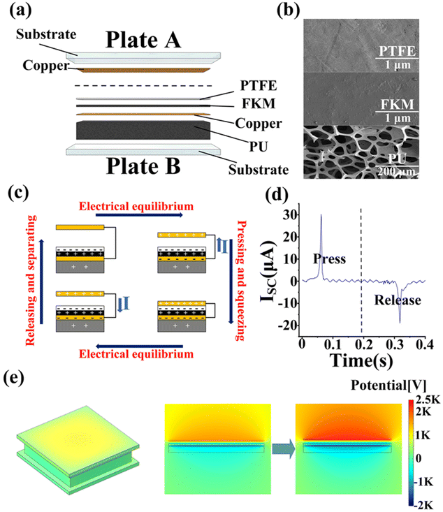
The composition of PFP-TENG is shown in Fig. 1a; the TENG (area: 7 cm × 7 cm) was composed of Plate A and B. Plate A consisted of a conductive copper foil and an acrylic substrate, which formed a simple triboelectric unit. PTFE, FKM, conductive copper, and PU were stacked successively and attached to the substrate to fabricate Plate B. The common double-sided adhesive was used to ensure bonding between the triboelectric materials. The wires from the conductive copper in Plate A and Plate B, respectively, were connected to the external circuit. The SEM images of PTFE, FKM, and PU are shown in Fig. 1b and Fig. S1–2.† To ensure the environmental adaptability of PFP-TENG in the working conditions and the universality of the preparation method, all experimental materials were purchased from an electronic mall, and no temperature or humidity control was involved in the preparation and testing processes. The testing temperature was about 20 °C–26 °C, and the humidity was about 53%–79%. The experimental platform was set on a mini workbench, and the reciprocating mechanism driven by a gear motor provided external excitation. Plate A was fixed on the flange and connected to the front end of the reciprocating mechanism. On the other side of the workbench, a right-angle holder and an L-shaped bracket were used to fix and brace Plate B so that it was parallel to and aligned with Plate A. The pressure range was 0–4.2 N, and the initial distance between the plates was 8 cm. The TENG output performance parameters presented in Fig. S3† were measured on DMM6500 and TBS1102X. TBS1102X was equipped with a high-resistance probe (100 MΩ) to measure the voltage parameters. The NPLC of DMM6500 was set to 0.01 to capture the current parameters. In addition, the electrometer model Keithley 6514 was used to test the transferred charge of the TENG.3. Results and discussion
The effectiveness and advantages of improving TENGs at the structural level have been fully proven. Generally, structural changes are aimed at increasing the charge density on the surface or reaching a charge-excited operating state to achieve a significant improvement in performance.20–24 In this work, a novel design based on a three-layer stacked structure working in the vertical contact separation mode was developed to obtain optimal results. The working principle of PFP-TENG is illustrated in Fig. 1c and d. When copper in Plate A presses and squeezes Plate B, according to the rule of electron flow from the low work function side to the higher work function side, the electrons begin to transfer from copper to the electronegative PTFE on Plate B.25 Meanwhile, extrusion occurs between PTFE and FKM, and FKM easily turns positive-charged by transmitting electrons to PTFE.13,24,26 Besides, PU undergoes compression deformation during extrusion, and a small amount of positive charge is also induced.24,27 Therefore, conductive copper, FKM, and PU on Plate B are positively charged, and PTFE is electronegative. To maintain the electrical equilibrium of the system, the conductive layer on Plate B absorbs electrons and generates induced current from Plate B to A in the external circuit.28 Similarly, when the plates are released and separated, the electrons return, and the opposite current is generated. By repeating this process, the PFP-TENG can continuously generate electricity. Fig. 1e and Video S1† show the potential distribution when the distance between the plates is 0.4 cm, as simulated in COMSOL by setting the charge density on the copper layer to 54.42 × 10⁻⁶ C m−2. In this case, as seen in Fig. 1c, there is a high potential difference between the conductive layers, resulting in a pulsed-induced current. The specific COMSOL modeling process is presented in the ESI.†Different from the dielectric–dielectric and conductive–dielectric material combinations in traditional vertical contact-separated TENGs, a novel design of conductive–dielectric–dielectric materials was chosen, ss shown in Fig. 2a. The output voltage of a vertical contact-separated TENG can be expressed as follows:29
 | (1) |
 | (2) |
According to the potential difference between the two electrodes, the V–Q–x relationship of the TENG is expressed as follows:
 | (3) |
Then, the corresponding output performance can also be derived as shown below:
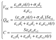 | (4) |
Evidently, this design is superior to the general vertical contact-separation mode TENG in terms of output voltage and charging capability. After proving the effectiveness of the stacked structure by the above theoretical model, the actual performance of the two designs was compared. As seen in Fig. 2c, compared with the dielectric–dielectric contact surface combination (PTFE-FKM), PFP-TENG displayed almost 5 times the maximum short-circuit current (ISC) and 55.1% augmentation in the amount of transferred charge. Notably, the extruded PU transported a small amount of charge to Electrode 2, turning electropositive to maintain the electrical balance inside the TENG system. In TENGs, if a certain dielectric layer is removed or the stacking sequence is changed to achieve a new charge distribution, the output voltage and the amount of charge transferred will be impaired. The influence of the thickness of PTFE on the device performance was explored, as shown in Fig. S7.† Our PFP-TENG showed the best performance when the thickness of PTFE was 1 mm. This can be because a thinner tribo-layer cannot generate and accumulate enough triboelectric charges, and can detach, tear or get damaged easily. However, if the tribo-layer is too thick, the generation and flow of induced charge on the conductive layer may be hindered, which will also impair the performance. Based on the above analysis, the output performance of a triboelectric nanogenerator can be improved significantly by introducing more dielectric layers and adopting specific stacking structures. The detailed theoretical derivation and the effect of PU are described in the ESI.†
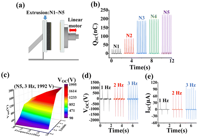
As shown in Fig. 3a, to carry out the quantitative analysis and research better, PFP-TENG was employed under different extrusion conditions by changing the number of acrylic plates (3 mm per plate) at the bottom of Plate B. The maximum pressure on the PFP-TENG surface was 4.2 N, which does not cause deformation of the substrate and additional acrylic plates. According to the number of plates, we could define five working states: N1–N5. In the initial state of no additional acrylic plate, the output performance of PFP-TENG was minimal because there was no triboelectric effect at the interface. The effect of the amount of extrusion is also reflected in the amount of transferred charge (QSC). As seen in Fig. 3b, when PU was squeezed (N2 → N3), the QSC of the TENG significantly improved, and the peak-to-peak value jumped from 86 nC to 189 nC. In N5, it reached 223 nC. Fig. 3c illustrates the influence of frequency and extrusion amount on VOC. There was no contact between Plate A and B at N1; hence, only a small amount of charge transfer was induced by inductive electrification, and the maximum VOC only reached 195.3 V. With two additional plates (N2), contact was established between PTFE and FKM, but PU was not compressed. Because of the coupling effect of triboelectrification and induction, the output was remarkably improved. The VOC at 1 Hz increased from 93.75 V to 390.6 V, while that at 3 Hz reached 1054 V. In N3, the PU layer deformed due to the squeezing of Plate A, the duration of contact was prolonged, and the bonding effect was optimal. Meanwhile, the electropositive PU was discharged, causing the copper layer on Plate B to induce more electrons, further enhancing the output. Owing to this, the VOC of N3 was almost 2.5 times that of N2, and the VOC reached 985 V at 1 Hz. With the N4–N5 transition, the VOC increased from 1532 V to 1640 V, respectively. However, with the deformation degree of PU deepening and nearing the limit, the increase in VOC slowed down, finally achieving its maximum point. As seen in Fig. 3d and e, under complete extrusion (N5), VOC and ISC gradually reached the maxima with the increase in frequency (1 Hz–3 Hz). At 1 Hz, the maximum instantaneous VOC and ISC were 1171 V and 30.9 μA, respectively, while at 3 Hz, they improved to 1992 V and 99 μA; the promotion of ISC was more than three times. Correspondingly, the amounts of transferred charge were 1.44 μC, 2.44 μC, and 3.42 μC. This can be explained by the accelerated transfer charge in the external circuit with the frequency. The maximum force between the plates enhanced from 1.4 N to 4.2 N, and the stronger crush also improved the synergy between the triboelectric layers.25,27 Therefore, these results exemplify that PFP-TENG with elastic characteristics can adapt to the changing environment and effectively adjust its output performance according to different extrusion conditions.
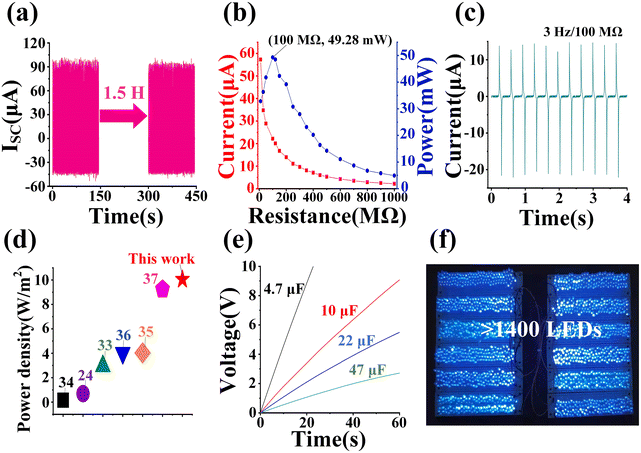
Next, the durability of PFP-TENG was investigated. Due to the elastic deformation of PU, which offers a buffer in the process of compression, the PTFE surface wear was reduced. As shown in Fig. 4a and Fig. S9,† even when PFP-TENG experienced a violent collision (N5, 3 Hz) for more than 1.5 hours, its surface of PTFE was not seriously damaged, and the ISC value did not decrease significantly and was maintained at about 95 μA. Furthermore, the maximum instantaneous output power of PFP-TENG under different loads is illustrated in Fig. 4b and c. With the external load increasing from 10 MΩ to 1000 MΩ, the maximum ISC decreased from 57.3 μA to 2.2 μA, and the point of peak-to-peak power located at 100 MΩ was 49.28 mW. This means a power density of 10.2 W m−2 (145.2 W m−3) was achieved, which exceeds the values of previous designs, as shown in Fig. 4d.24,33–37 Differentiating the general optimization on the material, our TENG design realizes excellent output performance because of the stacking of multiple tribo-layers, which is more efficient and cheaper in terms of device fabrication. It eliminates tedious chemical treatment and enables large-scale device production, further promoting the utility progress of TENGs. To investigate the practical application potential of PFP-TENG, it was used to charge commercial capacitors with capacitance values 4.7 μF, 10 μF, 22 μF and 47 μF; their potentials reached 18.32 V, 9.07 V, 5.49 V and 2.71 V (Fig. 4e), respectively, within 60 s. In addition, as shown in Fig. 4f, the TENG could light more than 1400 blue LEDs (light-emitting diodes) to a high brightness state, which also proves that it has excellent power density.
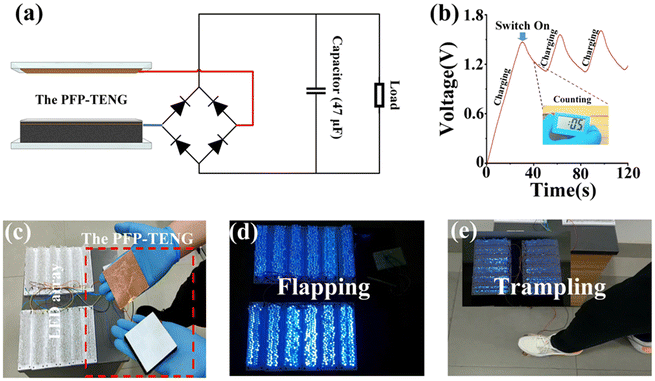
By connecting the PFP-TENG to a full-bridge rectifier circuit, electrical energy could be stored in the charging capacitor first and then utilized to drive low-power loads. As shown in Fig. 5a–b and Videos S2–S3,† after charging a 47 μF capacitor for 30 s, PFP-TENG could power an electronic clock to complete the 20 s timing task, and at the same charging time, a calculator (ADG98837), which was shielded from auxiliary power, could also be turned on to perform simple calculations. Apart from this, as shown in Fig. 5c–e and Videos S4–S6,† mechanical energy from the daily movements of the human body, such as flapping, trampling, and walking, could be used to light the LED array. This shows that, as a basic triboelectric unit, PFP-TENG has the potential to harvest discrete mechanical energy and provides a good foundation for the future development of a power generation device.
4. Conclusions
In summary, a new TENG design based on a multi-layer structure has been proposed. By adopting a specific stacking sequence, more induced charges could be generated on the conductive layer of the PFP-TENG, which resulted in a five-fold increase in ISC and a 55.10% higher total transfer charge than that of the traditional design under the same conditions. According to different extrusion environments, TENG is flexible and adjusts its output so that the VOC can be selected in the range of 195 V to 1992 V. Under maximum compression, it could reach an ISC of 99 μA and a QSC of 1.44 μC in one working cycle. When connected to the load circuit, PFP-TENG exhibited maximum output power densities of 10.2 W m−2 and 145.2 W m−3. More than 1400 LEDs could be lit in a high-brightness state using a contact area of 7 cm × 7 cm. The efficient capacitor charging ability indicates that the TENG has the ability to support micro-intelligent electronic devices. Besides, this TENG also shows great potential in collecting mechanical energy from daily human activities, demonstrating a considerable power conversion effect from pedestrian flapping, trampling, and walking. Therefore, this PFP-TENG design can promote the development of triboelectricity technology and the collection of discrete mechanical energy. Especially, as a basic triboelectric unit, it offers a reliable method for the performance optimization of TENGs, which is applied in different scenarios.Author contributions
Jianfeng Luo designed the experiments and fabricated the TENG. Anguo Liu, Xinyao Zhang and Guanyu Dai conducted the electrical measurements and data analysis. Xiaonan Su and Yilei Shao assisted in chart drawing and theoretical model building. The paper was written by Jianfeng Luo with contributions from all the co-authors. Yuxiang Su and Keyang Zhao supervised the research and revised this manuscript. Zhenhua Li and Xizeng Zhao provided some experimental methods. All the authors discussed the results and commented on the manuscript.Conflicts of interest
The authors declare no conflict of interest.Acknowledgements
This work was supported in part by the Projects of Zhoushan Science and Technology Planning (No. 2022C41009), National University Student Innovation and Entrepreneurship Training Plan (No. 202210340046), General Research Project of Education Department of Zhejiang Province (No. Y202250481).References
- B. Chen, Y. Yang and Z. L. Wang, Adv. Energy Mater., 2018, 8, 1702649 CrossRef.
- J. Li, J. Chen and H. Guo, Energies, 2021, 14, 6949 CrossRef.
- Y. Pang, Y. Cao, M. Derakhshani, Y. Fang, Z. L. Wang and C. Cao, Matter, 2021, 4, 116–143 CrossRef.
- J. Luo and Z. L. Wang, Energy Storage Mater., 2019, 23, 617–628 CrossRef.
- Z. L. Wang, J. Chen and L. Lin, Energy Environ. Sci., 2015, 8, 1–10 RSC.
- Z. Cao, Z. Wu, R. Ding, S. Wang, Y. Chu, J. Xu, J. Teng and X. Ye, Nano Energy, 2022, 93, 106891 CrossRef CAS.
- X. Shi, P. Chen, K. Han, C. Li, R. Zhang, J. Luo and Z. L. Wang, J. Mater. Chem. A, 2023, 11, 11730 RSC.
- S.-Y. Yun, I.-W. Tcho, W.-G. Kim, D.-W. Kim, J.-H. Son, S.-W. Lee and Y.-K. Choi, J. Mater. Chem. A, 2022, 10, 10383 RSC.
- G. Li, S. Fu, C. Luo, P. Wang, Y. Du, Y. Tang, Z. Wang, W. He, W. Liu, H. Guo, J. Chen and C. Hu, Nano Energy, 2022, 96, 107068 CrossRef CAS.
- Q. Xu, Y. Fang, Q. Jing, N. Hu, K. Lin, Y. Pan, L. Xu, H. Gao, M. Yuan, L. Chu, Y. Ma, Y. Xie, J. Chen and L. Wang, Biosens. Bioelectron., 2021, 187, 113329 CrossRef CAS PubMed.
- Q. Lian, Y. Liu, X. Zhang, L. Shan, X. Wu, H. Chen and T. Guo, IEEE Electron Device Lett., 2021, 42, 1334–1337 CAS.
- K. Xia, Y. Tian, J. Fu, Z. Zhu, J. lu, Z. Zhao, H. Tang, Z. Ye and Z. Xu, Nano Energy, 2021, 87, 106210 CrossRef CAS.
- H. Patnam, S. A. Graham, P. Manchi, M. V. Paranjape and J. S. Yu, Nanoscale, 2022, 14, 13236 RSC.
- C. Zhang, S. Li, Y. He, C. Chen, S. Jiang, X. Yang, X. Wang, L. Pan and Q. Wan, IEEE Electron Device Lett., 2020, 41, 617–620 CAS.
- S. Dong, F. Xu, Y. Sheng, Z. Guo, X. Pu and Y. Liu, Nano Energy, 2020, 78, 105327 CrossRef CAS.
- F. Xing, Y. Jie, X. Cao, T. Li and N. Wang, Nano Energy, 2017, 42, 138–142 CrossRef CAS.
- Y. Yun, S. Jang, S. Cho, S. H. Lee, H. J. Hwang and D. Choi, Nano Energy, 2021, 80, 105525 CrossRef CAS.
- Y. Chen, Y. Zhang, T. Zhan, Z. Lin, S. L. Zhang, H. Zou, G. Zhang, C. Zou and Z. L. Wang, Adv. Mater. Technol., 2019, 4, 105525 Search PubMed.
- J. Wang, J. He, L. Ma, Y. Yao, X. Zhu, L. Peng, X. Liu, K. Li and M. Qu, Chem. Eng. J., 2021, 423, 130200 CrossRef CAS.
- J. Chen and Z. L. Wang, Joule, 2017, 1, 1–42 CrossRef.
- H. Zou, Y. Zhang, L. Guo, P. Wang, X. He, G. Dai, H. Zheng, C. Chen, A. C. Wang, C. Xu and Z. L. Wang, Nat. Commun., 2019, 10, 1427 CrossRef PubMed.
- X. Yue, Y. Xi, C. Hu, X. He, S. Dai, L. Cheng and G. Wang, RSC Adv., 2015, 41, 32566–32571 RSC.
- Q. Li, S. Fu, X. Li, H. Chen, W. He, Q. Yang, X. Zhang, H. Yang, D. Ren and Y. Xi, Energy Environ. Sci., 2023, 8, 3514–3525 CrossRef.
- Q. Li, Y. Hu, Q. Yang, X. Li, X. Zhang, H. Yang, P. Ji, Y. Xi and Z. L. Wang, Adv. Energy Mater., 2023, 13, 2202921 CrossRef CAS; S. Hao, J. Jiao, Y. Chen, Z. L. Wang and X. Cao, Nano Energy, 2020, 75, 104957 CrossRef.
- H. Gao, M. Hu, J. Ding, B. Xia, G. Yuan, H. Sun, Q. Xu, S. Zhao, Y. Jiang, H. Wu, M. Yuan, J. Li, B. Li, J. Zhao, D. Rao and Y. Xie, Adv. Funct. Mater., 2023, 33, 2213410 CrossRef CAS.
- Y. Liu, Y. Zheng, Z. Wu, L. Zhang, W. Sun, T. Li, D. Wang and F. Zhou, Nano Energy, 2021, 79, 105422 CrossRef CAS.
- J. Luo, Y. Su, C. Zhang, Y. Gu, A. Liu, Z. Li, W. Feng and K. Zhao, Nano Energy, 2022, 103, 107859 CrossRef CAS.
- J. Cheng, X. Zhang, T. Jia, Q. Wu, Y. Dong and D. Wang, Nano Energy, 2022, 102, 107622 CrossRef CAS.
- P. Cheng, H. Guo, Z. Wen, C. Zhang, X. Yin, X. Li, D. Liu, W. Song, X. Sun, J. Wang and Z. L. Wang, Nano Energy, 2019, 57, 432–439 CrossRef CAS.
- K. Xia, J. Fu and Z. Xu, Adv. Energy Mater., 2020, 10, 2000426 CrossRef CAS.
- H. Zhang, P. Zhang, L. Deng and X. Fan, Appl. Phys. Lett., 2022, 121, 063902 CrossRef CAS.
- J. Shao, M. Willatzen and Z. L. Wang, J. Appl. Phys., 2020, 128, 111101 CrossRef CAS.
- Z. Haider, A. Haleem, R. u. S. Ahmad, U. Farooq, L. Shi, U. P. Claver, K. Memon, A. Fareed, I. Khan, M. K. Mbogba, S. M. C. Hossain, F. Farooq, W. Ali, M. Abid, A. Qadir, W. He, J. Luo and G. Zhao, Nano Energy, 2020, 68, 104294 CrossRef CAS.
- S. Hao, J. Jiao, Y. Chen, Z. L. Wang and X. Cao, Nano Energy, 2020, 75, 104957 CrossRef CAS.
- T. Jing, B. Xu, Y. Yang, M. Li and Y. Gao, Nano Energy, 2020, 78, 105373 CrossRef CAS.
- S. M. S. Rana, M. T. Rahman, M. Salauddin, S. Sharma, P. Maharjan, T. Bhatta, H. Cho, C. Park and J. Y. Park, ACS Appl. Mater. Interfaces, 2021, 13, 4955–4967 CrossRef CAS PubMed.
- M. Salauddin, S. M. S. Rana, M. Sharifuzzaman, M. T. Rahman, C. Park, H. Cho, P. Maharjan, T. Bhatta and J. Y. Park, Adv. Energy Mater., 2021, 11, 2002832 CrossRef CAS.
Footnote |
| † Electronic supplementary information (ESI) available. See DOI: https://doi.org/10.1039/d3nr04060g |
| This journal is © The Royal Society of Chemistry 2024 |

