Efficient all-fluorescence white organic light-emitting diodes with superior color stability and low efficiency roll-off employing matrix-free blue emitting layers†
Yuan
Liu
 *a,
Rui
Xue
a,
Deng-Feng
Li
a,
Ya-Nan
Li
a,
Yuan-Bo
Zhang
a,
Sheng-Zhe
Huang
a,
Chun-Fang
Zhang
a,
Qi
Feng
a,
Tian-Yi
Li
 *b and
Lin-Song
Cui
*cd
aSchool of Instrument Science and Optoelectronic Engineering, Beijing Information Science & Technology University, No. 12 xiaoying East Road, Beijing, 100192, China. E-mail: yuan.liu@bistu.edu.cn
bSchool of Chemistry and Biological Engineering, Department of Chemistry, University of Science and Technology Beijing, 30 Xueyuan Road, Beijing, 100083, China. E-mail: litianyi@ustb.edu.cn
cKey Laboratory of Precision and Intelligent Chemistry, University of Science and Technology of China, Hefei, Anhui 230026, China
dCAS Key Laboratory of Soft Matter Chemistry, Department of Polymer Science and Engineering, University of Science and Technology of China, Hefei, Anhui 230026, China. E-mail: lscui@ustc.edu.cn
First published on 26th July 2024
Abstract
All-fluorescence white organic light-emitting diodes (WOLEDs) based on thermally activated delayed fluorescence (TADF) have great potential for large-area light sources. However, designing all-fluorescence WOLEDs that can simultaneously achieve high efficiency, low efficiency roll-off, and excellent color stability with simplified device architectures is still challenging. Herein, we report a simplified three-color all-fluorescence WOLED comprising a matrix-free TADF blue emitting layer (EML) and sensitized EMLs. By broadening exciton distribution and reducing exciton losses through multiple sensitizing processes using an advanced triple-EML configuration, we simultaneously improve the color stability and reduce the efficiency roll-off of DMAC-DPS-based all-fluorescence WOLEDs. Moreover, by introducing a blue emitter Cz-TRZ3 to enhance the charge balance, the all-fluorescence WOLED reaches a maximum external quantum efficiency (EQE) of 24.3% and maintains 22.4% and 19.6% at 100 and 1000 cd m−2, respectively. Remarkably, the device shows extremely color stable electroluminescence spectra with a negligible chromaticity coordinate shift of (0.001, 0.004) in a wide luminance range of 1000–10![[thin space (1/6-em)]](https://www.rsc.org/images/entities/char_2009.gif) 000 cd m−2. Our results provide a universal strategy to achieve all-fluorescence WOLEDs with low efficiency roll-off and superior color stability.
000 cd m−2. Our results provide a universal strategy to achieve all-fluorescence WOLEDs with low efficiency roll-off and superior color stability.
Introduction
White organic light emitting diodes (WOLEDs) are emerging as the kernel for the next-generation lighting sources due to the excellent advantages of high internal quantum efficiencies, low driving voltages, and scalable fabrication processes.1 According to spin statistics, there are mainly two material systems that have been developed to realize 100% internal quantum efficiency, i.e., phosphorescent2 and thermally activated delayed fluorescence (TADF) emitters.3 However, the former one is restricted by the low stability of the blue phosphorescent emitters, unclear toxicities of rare-metal materials, and the high cost in mass production.4–6 All-fluorescence WOLEDs based on TADF materials are therefore proposed to overcome these challenges. With a small energy gap (ΔEST) between the lowest excited singlet state (S1) and lowest excited triplet state (T1) in TADF materials, they can harness 100% electrogenerated excitons using an efficient reverse intersystem crossing (RISC) process.7 Moreover, hyperfluorescent (HF) OLEDs that use TADF materials as sensitizers for conventional fluorescent (CF) emitters through long-range Förster resonance energy transfer (FRET) processes also realize maximum EQEs beyond 20%, which greatly enriches emitter diversity and provides new opportunities for realizing stable and high color quality all-fluorescence OLEDs.8–10For highly efficient HF all-fluorescence WOLEDs, a high utilization efficiency of electrogenerated excitons is a prerequisite. Adachi et al. reported pioneering work on HF all-fluorescence WOLEDs that adopted an efficient blue TADF molecule (DMAC-DPS) to sensitize CF green and red emitters, reaching an EQE of 12.1%.11 However, it still causes inevitable exciton losses because of the complicated and long exciton transfer channels. In 2016, Su et al. reported an all-fluorescence WOLED with a high CRI of 95 using a chromaticity adjustable yellow TADF emitter to sensitize a deep red emitter DBP, reaching a maximum EQE of 15.6%.12 Very recently, by reducing triplet exciton diffusion with a blue TADF emitter containing a large steric hindrance and accurately controlling the doping concentration of CF emitters, HF all-fluorescence WOLEDs also realized nearly 100% exciton utilization efficiency.13,14 All these results indicate that 100% electrogenerated exciton harvesting for HF all-fluorescence WOLEDs is achievable, providing a cost-effective approach for efficient WOLEDs. Though impressive device efficiencies were reached, due to the limited upconverting rate from triplet to singlet, the long-lived triplet exciton leads to severe bimolecular reactions such as triplet–triplet and singlet–triplet annihilation and therefore induce large efficiency roll-off.7,15,16
To reduce the efficiency roll-off of all-fluorescence WOLEDs, extending the recombination zone to dilute the exciton density is considered an effective approach.17 Various host materials such as single bipolar materials, co-host systems, CT-type materials, and TADF materials were introduced to broaden the recombination zone.18,19 Specifically, the matrix-free hyperfluorescent device was proposed, where bipolar blue emitting TADF materials can not only emit blue light themselves but also sensitize long wavelength CF or multi-resonant TADF emitters through efficient FRET.20–22 Moreover, the driving voltage of the matrix-free device can also be reduced by eliminating the energy offset between host and guest molecules. At the same time, the device structure is greatly simplified, which is favorable for eventual OLED manufacture.23 These properties establish a new paradigm for developing efficient all-fluorescence OLEDs. Lee et al. developed a deep blue TADF emitter CzAcSF as the host materials for blue and yellow fluorescent emitters, reaching 14.0% EQE of HF all-fluorescence WOLEDs.24 Recently, Liu et al. extended this concept by introducing a steric molecule with high photoluminescence quantum yield (PLQY) and balanced ambipolar charge transport ability in neat solid film, reaching simplified warm WOLEDs with an EQE over 30% and a luminous efficacy over 130 lm W−1.25 Nevertheless, these devices still suffer from notorious color shift under different luminance levels, primarily stemming from the changeful exciton allocation and various exciton quenching effects with increasing driving voltages.26,27 Especially in display applications, color shifts can lead to obvious visual alterations, as our human eyes are sensitive to color stability. In general, the color shift of CIE (Commission Internationale de l’Éclairage) coordinates for both the x- and the y-value should be less than 0.005–0.01 in practical application.26,28 Consequently, rational design strategies for simultaneously realizing simplified device architectures, high exciton utilization efficiency, low efficiency roll-off, and superior color stability are highly desired.
Here, we systematically exploit simplified white OLEDs with matrix-free blue EMLs. By carefully allocating exciton distribution and transfer routes in the multi-EMLs, we design a white OLED with low efficiency roll-off and stable electroluminescence (EL) spectra, realizing a maximum EQE of 20.2% and a CRI of 83 and a CIE coordinate of (0.329, 0.389). Furthermore, we improve the charge balance of neat blue EML using a TADF emitter Cz-TRZ3, the efficiency roll-off of the all-fluorescence WOLEDs is further reduced, reaching a maximum EQE of 24.3% and keeping 19.6% at the practical luminance 1000 cd m−2. Moreover, the devices provide extremely stable EL spectra with a CRI of 83 in a wide luminance range of 1000–10![[thin space (1/6-em)]](https://www.rsc.org/images/entities/char_2009.gif) 000 cd m−2.
000 cd m−2.
Results and discussion
Monochrome fluorescent OLEDs
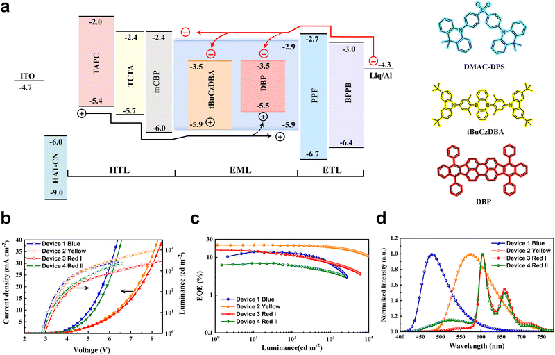
To determine the performance of monochrome OLEDs with matrix-free blue emitting layers, a device architecture of ITO/HAT-CN (5 nm)/TAPC (40 nm)/TCTA (10 nm)/mCBP (5 nm)/EML (25 nm)/PPF (10 nm)/PBPPhen (40 nm)/Liq (2 nm)/Al (150 nm) was adopted. Here, HAT-CN and Liq were used as the hole injection layer and electron injection layer, respectively. The organic materials TAPC and PBPPhen with high mobility are adopted as the hole transport layer and electron transport layer, respectively. To confine excitons in EMLs, mCBP and PPF with high triplet energies were utilized as exciton blocking layers. DMAC-DPS (device 1), DMAC-DPS:10 wt% tBuCzDBA (device 2) and DMAC-DPS:10 wt% tBuCzDBA:1 wt% DBP (device 3) were used as blue, yellow, and red emitting layers, respectively. The energy level diagram of the devices is displayed in Fig. 1a. As the bipolar matrix-free DMAC-DPS was directly used as the recombination layer, the blue OLED (device1) realizes a small driving voltage (3.5 V for 100 cd m−2, Table S1, ESI†) with a maximum EQE of 14.0% and an EL spectrum peaked at 478 nm, which is comparable to the reported values.20,22 A doped device was also fabricated for comparison. As shown in Fig. S1 (ESI†), the matrix-free blue OLED shows a lower driving voltage than the doped device, which can be beneficial for improving the luminous efficacy of WOLEDs. For the yellow OLED (device 2), 10 wt% tBuCzDBA was doped in DMAC-DPS. As shown in Fig. 1a, tBuCzDBA has the same HOMO level as DMAC-DPS (HOMO = 5.9 eV),29 whereas a much deeper LUMO than that of DMAC-DPS.30 The 0.6 eV LUMO energy offset means electrons can be easily captured by tBuCzDBA, leading to a trap-assisted recombination process for yellow OLEDs.31,32 Therefore, the yellow OLED exhibits a larger driving voltage than that of blue OLEDs as the charge trapping on the emitters decreases carrier mobility in the EMLs (Fig. 1b).33 A maximum EQE of 22.8% and low efficiency roll-off are reached in the yellow OLED as tBuCzDBA has a small ΔEST of 22 meV and a short delayed fluorescence lifetime of 2.1 μs and a preferred orientation factor of 0.83.30 At the luminance of 100 cd m−2 and 1000 cd m−2, the efficiency remains 20.7% and 18.7%, according to an efficiency roll-off of 9.6% and 18.0%, respectively. As depicted in Fig. 1d, the yellow OLED shows an EL emission peak at 575 nm and a full width at half maximum (FWHM) of 110 nm, reaching a CIE coordinate of (0.482, 0.506). To realize deep red emission, a fluorescent emitter DBP with a singlet energy of 2.07 eV was adopted. As there is a large overlap between tBuCzDBA emission and DBP absorption (Fig. S2, ESI†), the FRET is suggested to be efficient, and the FRET radius is calculated to be 8.3 nm. Assuming 1 nm molecule size for all the organic materials, the average distance is calculated to be 5.8 nm for the red emitters DBP with a doping concentration of 0.5 wt%.34,35 This ensures the singlet excitons on tBuCzDBA can be efficiently harvested by the red emitter DBP. As shown in Fig. 1c, the red OLED (device 3) shows an EL spectrum peaked at 605 nm with a small fraction emission from yellow emitter tBuCzDBA, reaching a CIE coordinate of (0.625, 0.368). The red OLED exhibits a maximum EQE of 16.2%, which is comparable to the best reported values.36 To elucidate the exciton transfer process between blue, yellow, and red emitters, we also fabricated device 4 with an EML of DMAC-DPS:1 wt% tBuCzDBA:1 wt% DBP. The maximum EQE of device 4 is 7.0%, which is much lower compared to device 3, indicating severe exciton quenching by the red emitter DBP. It was reported that the symmetrically bar-shaped structure of DMAC-DPS facilities intermolecular interactions and promotes the triplet exciton diffusion length.13 In the EML with a low doping concentration of tBuCzDBA, the triplet excitons generated on DMAC-DPS cannot be efficiently transferred to the yellow emitter tBuCzDBA, and therefore quenching by DBP through Dexter energy transfer from DMAC-DPS to DBP or emitting as a blue emission. Also, as the spatial distance is extended between yellow and red emitters, device 4 shows much stronger yellow emission than that of device 3 because the FRET rate of singlet excitons decreases exponentially as the distance increases (Fig. 1d).All-fluorescence white OLEDs
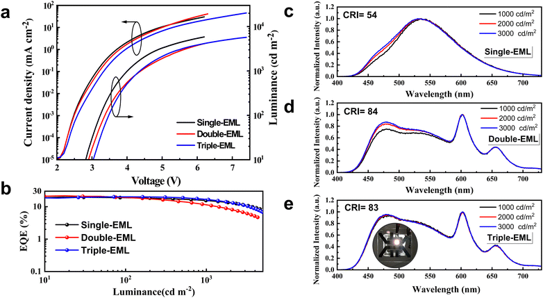
Inspired by efficient monochrome OLEDs, we designed the white OLEDs with the same device structure except for the EMLs. To reach complementary two-color WOLEDs, a single-EML of DMAC-DPS: tBuCzDBA (0.5 wt%, 25 nm) (device W1) was adopted. As shown in Fig. 2a, device W1 reaches a comparable low driving voltage (3.2 V for 100 cd m−2) as the monochrome blue device. This means at a low doping concentration, the trapping-assisted recombination by yellow emitter tBuCzDBA is greatly suppressed. A maximum EQE of 21.0% is realized by W1. By introducing the yellow emitter, the efficiency roll-off is remarkably improved. The device keeps 91% and 74% of the maximum efficiency at 100 cd m−2 and 1000 cd m−2, respectively (as concluded in Table 1). Combining the low driving voltages and high EQE, device W1 reaches a maximum luminous efficacy of 72.5 lm W−1. However, because of the lack of emission in the red range, device W1 only reaches a CRI of 54 with a CIE of (0.340, 0.499) at 1000 cd m−2, which is not sufficient for indoor illumination.37,38| Device | V (V) | EQEb [%] | CEb [cd A−1] | LEb [lm W−1] | CIEc | CRIc | Roll-offd (%) |
|---|---|---|---|---|---|---|---|
| a At a luminance of 1 cd m−2. b Efficiencies of the maximum, at 100 cd m−2 and at 1000 cd m−2. c At a luminance of 1000 cd m−2. d At a luminance of 3000 cd m−2. | |||||||
| W1 | 2.6 | 21.0/19.1/15.5 | 62.4/59.5/46.1 | 72.5/58.4/36.2 | (0.340, 0.499) | 54 | 47 |
| W2 | 2.6 | 21.8/19.0/11.4 | 52.5/43.9/25.6 | 58.9/40.5/18.3 | (0.350, 0.394) | 84 | 71 |
| W3 | 2.7 | 20.2/20.1/16.6 | 51.2/50.2/39.2 | 52.9/45.1/28.0 | (0.329, 0.389) | 83 | 46 |
| W4 | 3.1 | 24.3/22.4/19.6 | 60.8/56.1/49.2 | 63.7/47.6/33.6 | (0.420, 0.469) | 83 | 25 |
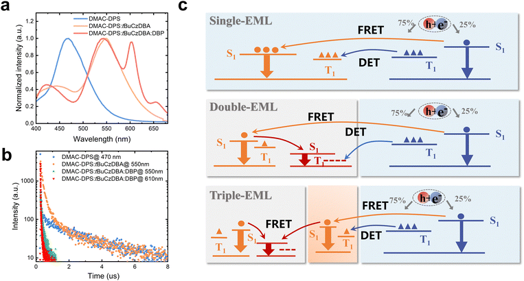
To improve the color quality, a deep red CF emitter DBP with high PLQY was introduced to improve the CRI. We designed white OLEDs with double- and triple-EMLs. DMAC-DPS: tBuCzDBA:DBP (10 wt%, 0.5 wt%, 15 nm)/DMAC-DPS (10 nm) (device W2) and DMAC-DPS: tBuCzDBA:DBP (10 wt%, 0.5 wt%, 13 nm)/DMAC-DPS: tBuCzDBA (10 wt%, 2 nm)/DMAC-DPS (10 nm) (device W3) were adopted as the EMLs. The molecular structures of all the adopted materials and the device architecture for WOLEDs are depicted in Fig. S3 (ESI†). Both device W2 and W3 realize high color quality, with a CRI of 84 and 83, and CIE coordinates of (0.350, 0.394) and (0.329, 0.389) at 1000 cd m−2, respectively. Interestingly, device W3 reaches obviously better color stability and lower efficiency roll-off than those of device W2 in the practical luminance range of 1000–3000 cd m−2. Device W2 and W3 reach a comparable maximum EQE (21.8% and 20.2% for W2 and W3, respectively) (Fig. 2b). As depicted in Fig. 2e and Fig. S4 (ESI†), the photon contribution from blue, yellow, and red emission for W3 are 44%, 21% and 35%, respectively. However, device W3 reaches better performance than the efficiency of 16.6% according to the monochronic photon contribution. This suggests the exciton unitization efficiency is effectively improved in all fluorescence WOLEDs. At the luminance of 1000 cd m−2, the EQE remains at 11.4% and 16.6% for device W2 and W3, respectively, according to an efficiency roll-off of 48% and 18%. We attributed the improved color stability and reduced efficiency roll-off of device 3 to a stabilized exciton generation zone and efficient transfer processes. As shown in Fig. 3, the pure DMAC-DPS film and DMAC-DPS:10 wt% tBuCzDBA show typical TADF characters, reaching a delayed lifetime of 3.1 μs and 3.9 μs, respectively (Fig. 3b). With a small (0.5 wt%) doping concentration of DBP, the delayed lifetime of tBuCzDBA (550 nm) dramatically reduced to 101 ns. Also, the CF emitter DBP (610 nm) demonstrates a delayed component. This indicates efficient FRET from tBuCzDBA to DBP. Based on transient PL results, we propose the exciton generation and transfer processes as shown Fig. 3c. In device W1, the exciton for tBuCzDBA emission mainly transfers from DMAC-DPS at a low doping concentration of tBuCzDBA. In devices W2 and W3, the radiative singlet excitons on red emitters DBP are mainly from two routes: one is from tBuCzDBA (trap-assisted generated excitons) to DBP and the other one is from DMAC-DPS to tBuCzDBA to DBP. At low luminance, all excitons can be completely utilized as devices W2 and W3 achieve a comparable maximum EQE. At high luminance, the exciton density on blue EMLs which is adjusted to the yellow/red EMLs is increased. With the long triplet diffusion length of DMAC-DPS,15 the triplet excitons on DMAC-DPS are inevitably transferred to the red emitters DBP through Dexter energy transfer, leading to triplet exciton quenching on DBP. This is consistent with the low efficiency of monochrome device 4. In contrast, in the triple-EML device W3, the blue emitter and red emitter are spaced by a yellow EML. The accumulated triplet excitons on DMAC-DPS emitters will not be directly transferred to DBP but will still be from DMAC-DPS to tBuCzDBA and then to DBP. Therefore, the triplet exciton quenching route from blue emitter DMAC-DPS to red emitter DBP is blocked. On the other hand, as mentioned above, the tBuCzDBA emission is greatly overlapped with the absorption spectra of DBP, leading to a large FRET radius (8.3 nm) between yellow emitter tBuCzDBA and red emitter DBP. Combining the thick yellow/red (13 nm) EML and the large FRET radius, the number of red emitters is adequate to reach a stable FRET process even under high luminance. All these reasons endow low efficiency roll-off and superior color stability for device W3 with triple-EMLs.
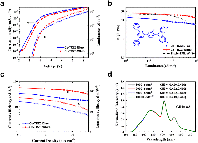
To further decrease color shift and efficiency roll-off, we adopted a rigid molecule 9-(4-(4,6-diphenyl-1,3,5-triazin-2-yl)-2-methylphenyl)-3,6-dimethyl-9H-carbazole (Cz-TRZ3) with a high PLQY of 92% and a small ΔEST of 0.17 eV.39 The blue and white device architectures are the same as device 1 and device W3, with Cz-TRZ3 (25 nm) (device 5) and Cz-TRZ3: tBuCzDBA:DBP (10 wt%, 0.5 wt%, 13 nm)/Cz-TRZ3: tBuCzDBA (10 wt%, 2 nm)/Cz-TRZ3 (10 nm) (device W4) for blue and white OLEDs, respectively. As shown in Fig. 4, the blue and white OLEDs reach a maximum EQE of 14.5% and 24.3%, respectively. As shown in Fig. S5 (ESI†), the blue OLED reaches a sky blue EL spectrum peaked at 495 nm with a CIE coordinate of (0.271, 0.435). At the practical luminance of 1000 and 3000 cd m−2, device W4 still maintains an EQE of 19.6% and 18.1%, which is apparently better than that of device W3 (Fig. 4b). Moreover, device W4 shows exceptional color stability, exhibiting a negligible chromaticity coordinate shift of (0.001, 0.004) across a broad luminance range from 1000 to 10![[thin space (1/6-em)]](https://www.rsc.org/images/entities/char_2009.gif) 000 cd m−2 (Fig. S6, ESI†).
000 cd m−2 (Fig. S6, ESI†).
This future confirms the validity of our triple-EML design strategy.
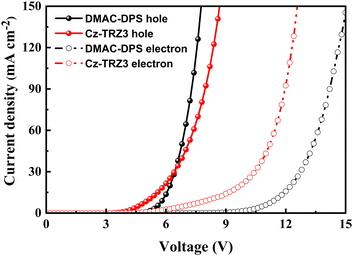
We attribute the improved efficiency roll-off and excellent color stability to the balanced charge transport ability. Cz-TRZ3 is composed of a carbazole-based moiety as a donor and a cyaphenine as an acceptor. As cyaphenine is a strong acceptor, more charge balance is expected in Cz-TRZ3. As shown in Fig. 5, DMAC-DPS reaches a slightly better hole transport ability than Cz-TRZ3. However, the electron transport ability of Cz-TRZ3 is much better than that of DMAC-DPS, indicating more charge balance can be realized in Cz-TRZ3-based devices. The balanced charge transport ability furnishes a broad and stabilized recombination zone, subsequently resulting in low efficiency roll-off and stable EL emission.
Experimental
Materials
The compounds 1,4,5,8,9,11-hexaazatriphenylenehexacarbonitrile (HAT-CN), 1,1-bis[(di-4-tolylamino)phenyl]cyclohexane (TAPC), tris(4-carbazoyl-9-ylphenyl)amine (TCTA), 3,3′-di(9H-carbazol-9-yl)-1,1′-biphenyl(mCBP),10,10′-(4,4′-sulfonylbis(4,1-phenylene))bis(9,9-dimethyl-9,10-dihydroacridine) (DMAC-DPS) and 8-hydroxyqui-noline-lithium, 8-hydroxyquinoline-lithium (Liq) were purchased from Xi'an Polymer Light Technology Corp. 2,8-Bis(diphenylphosphoryl)dibenzo[b,d]furan (PPF) and 2,2'-(1,3-phenylene)bis[9-phenyl-1,10-phenanthroline] (PBPPhen) were from Shenzhen Puri Materials Corp. 5,10-Bis (4-(3,6-di-tert-butyl-9H-carbazol-9-group)-2, 6-dimethyl-phenyl)-5, 10-dihydroboranthracene (tBuCzDBA) and dibenzo-4,4,7,7-tetrapheny-ldiindene[1,2,3-cd:perylene 1,2,3-lm] perylene (DBP) were purchased from Luminescence technology corp.Device fabrication and characterization
The devices were deposited on a patterned indium tin oxide (ITO, 110 nm) coated glass substrate, which was ultrasonically cleaned with acetone, ethanol, and deionized water for 10 min in sequence. Before deposition, the cleaned glass was treated with an ultraviolet ozone machine for 15 minutes. All the organic and metal layers were deposited in a vacuum chamber with a base pressure of 10−8 mbar. The film thickness, deposition rate, and doping concentration were in situ monitored using a calibrated quartz crystal. The deposition rate for organic layers and metal layers is 1–2 Å s−1 and 2–3 Å s−1, respectively. The active area of the devices is 9 mm2, determined by the overlap between anode ITO and cathode Al. After deposition, the devices were encapsulated with a glass lid and a UV-epoxy resin in the glass box. The current density–voltage–luminance (J–V–L) curves were performed using an automated system which consists of a Keithley 2420 source meter, silicon photodiode, and calibrated spectrometer (Ocean Insight QE-PRO spectrometer). The EQE of the devices was measured in a calibrated integrating sphere (Ocean Insight SPECTRUMTEQ-EQY). The absorption spectrum is recorded on a Shimadzu SOLIDSPEC3700 DUV-VIS-NIR spectrophotometer. Transient PL was measured using an Edinburgh FS5 spectrometer.Conclusions
In summary, we successfully designed highly efficient all-fluorescence WOLEDs with a simplified device using matrix-free blue EMLs. The proposed triple-EML architecture not only reduces efficiency roll-off at high luminance but also stabilizes the EL spectrum. With this design, all-fluorescence WOLEDs based on DMAC-DPS realize a maximum external quantum efficiency of 20.2% and reduced electroluminescence spectrum shift. By introducing a blue emitter with excellent charge balance ability, all-fluorescence white OLEDs realize a maximum EQE of 24.3% and a small efficiency roll-off. More impressively, the devices show superior color stability in a wide luminance range of 1000–10![[thin space (1/6-em)]](https://www.rsc.org/images/entities/char_2009.gif) 000 cd m−2 with a color rendering index of 83. Our design provides a potential device design strategy for high performance all-fluorescence WOLEDs with simplified device structures.
000 cd m−2 with a color rendering index of 83. Our design provides a potential device design strategy for high performance all-fluorescence WOLEDs with simplified device structures.
Author contributions
Y. L., T. Y. L., and L. S. C. conceived the concept and supervised the project. Y. L., X. R., D. F. L., Y. N. L., and Y. B. Z. designed the experiments and conducted the device measurements. S. Z. H., C. F. Z., and Q. F. analyzed the data. L. S. C. synthesised Cz-TRZ3. T. Y. L. performed transient PL measurements. The manuscript was written through contributions of all authors. All authors have given approval to the final version of the manuscript.Data availability
The authors confirm that the data supporting the findings of this study are available from the corresponding author upon reasonable request.Conflicts of interest
There are no conflicts to declare.Acknowledgements
This project was financially supported by the National Natural Science Foundation of China (Grant No. 62105039, 22205014 and 52103242), the R&D Program of Beijing Municipal Education Commission (Grant No. KM202211232015), and the Beijing Municipal Natural Science Foundation (Grant No. 2232036). This project was also funded by the Young Elite Scientist Sponsorship Program by the China Association for Science and Technology (Grant No. YESS20200146) and the Key training project of Beijing Information Science & Technology University (Grant No. 2121YJPY208). The numerical calculations in this paper were performed on the supercomputing system in the Supercomputing Center of the University of Science and Technology of China. This work was partially carried out at the Instruments Center for Physical Science, University of Science and Technology of China.References
- S. Reineke, M. Thomschke, B. Lüssem and K. Leo, Rev. Mod. Phys., 2013, 85, 1245–1293 CrossRef CAS.
- M. A. Baldo, D. F. O'Brien, Y. You, A. Shoustikov, S. Sibley, M. E. Thompson and S. R. Forrest, Nature, 1998, 395, 151–154 CrossRef CAS.
- H. Uoyama, K. Goushi, K. Shizu, H. Nomura and C. Adachi, Nature, 2012, 492, 234–238 CrossRef CAS PubMed.
- Y. Zhang, J. Lee and S. R. Forrest, Nat. Commun., 2014, 5, 5008 CrossRef CAS PubMed.
- A. Monkman, ACS Appl. Mater. Interfaces, 2022, 14, 20463–20467 CrossRef CAS PubMed.
- H. Zhao, C. E. Arneson, D. Fan and S. R. Forrest, Nature, 2024, 626, 300–305 CrossRef CAS PubMed.
- L.-S. Cui, A. J. Gillett, S.-F. Zhang, H. Ye, Y. Liu, X.-K. Chen, Z.-S. Lin, E. W. Evans, W. K. Myers, T. K. Ronson, H. Nakanotani, S. Reineke, J.-L. Bredas, C. Adachi and R. H. Friend, Nat. Photonics, 2020, 14, 636–642 CrossRef CAS.
- H. Nakanotani, T. Higuchi, T. Furukawa, K. Masui, K. Morimoto, M. Numata, H. Tanaka, Y. Sagara, T. Yasuda and C. Adachi, Nat. Commun., 2014, 5, 4016 CrossRef CAS PubMed.
- D. Zhang, L. Duan, C. Li, Y. Li, H. Li, D. Zhang and Y. Qiu, Adv. Mater., 2014, 26, 5050–5055 CrossRef CAS PubMed.
- K. Stavrou, L. G. Franca, A. Danos and A. P. Monkman, Nat. Photonics, 2024, 18, 554–561 CrossRef CAS.
- T. Higuchi, H. Nakanotani and C. Adachi, Adv. Mater., 2015, 27, 2019–2023 CrossRef CAS PubMed.
- X. L. Li, G. Xie, M. Liu, D. Chen, X. Cai, J. Peng, Y. Cao and S. J. Su, Adv. Mater., 2016, 28, 4614–4619 CrossRef CAS PubMed.
- D. Ding, Z. Wang, C. Duan, C. Han, J. Zhang, S. Chen, Y. Wei and H. Xu, Research, 2022, 2022, 0009 CrossRef CAS.
- P. C. Wei, D. D. Zhang and L. Duan, Adv. Funct. Mater., 2020, 30, 1907083 CrossRef CAS.
- C. Yin, Y. Zhang, T. Huang, Z. Liu, L. Duan and D. Zhang, Sci. Adv., 2022, 8, eabp9203 CrossRef CAS PubMed.
- K. Masui, H. Nakanotani and C. Adachi, Org. Electron., 2013, 14, 2721–2726 CrossRef CAS.
- C. Murawski, K. Leo and M. C. Gather, Adv. Mater., 2013, 25, 6801–6827 CrossRef CAS PubMed.
- T. Chatterjee and K. T. Wong, Adv. Opt. Mater., 2018, 7, 1800565 CrossRef.
- Y.-B. Zhang, Y.-N. Li, C.-F. Zhang, J.-B. Liu, J.-R. Li, H.-D. Bian, L.-Q. Zhu, J.-Z. Ou, L.-S. Cui and Y. Liu, Nanoscale, 2023, 15, 14249–14256 RSC.
- Q. Zhang, D. Tsang, H. Kuwabara, Y. Hatae, B. Li, T. Takahashi, S. Y. Lee, T. Yasuda and C. Adachi, Adv. Mater., 2015, 27, 2096–2100 CrossRef CAS PubMed.
- H. H. Cho, A. S. Romanov, M. Bochmann, N. C. Greenham and D. Credgington, Adv. Opt. Mater., 2020, 9, 2001965 CrossRef.
- H. H. Cho, D. G. Congrave, A. J. Gillett, S. Montanaro, H. E. Francis, V. Riesgo-Gonzalez, J. Ye, R. Chowdury, W. Zeng, M. K. Etherington, J. Royakkers, O. Millington, A. D. Bond, F. Plasser, J. M. Frost, C. P. Grey, A. Rao, R. H. Friend, N. C. Greenham and H. Bronstein, Nat. Mater., 2024, 23, 519–526 CrossRef CAS PubMed.
- Y. Liu, B. Nell, K. Ortstein, Z. Wu, Y. Karpov, T. Beryozkina, S. Lenk, A. Kiriy, K. Leo and S. Reineke, ACS Appl. Mater. Interfaces, 2019, 11, 11660–11666 CrossRef CAS PubMed.
- W. Song, I. Lee and J. Y. Lee, Adv. Mater., 2015, 27, 4358–4363 CrossRef CAS PubMed.
- H. Liu, Y. Fu, B. Z. Tang and Z. Zhao, Nat. Commun., 2022, 13, 5154 CrossRef CAS PubMed.
- M. C. Gather, R. Alle, H. Becker and K. Meerholz, Adv. Mater., 2007, 19, 4460–4465 CrossRef CAS.
- S. Chen, Q. Wu, M. Kong, X. Zhao, Z. Yu, P. Jia and W. Huang, J. Mater. Chem. C, 2013, 1, 3508–3524 RSC.
- S. B. Li, W. D. Sun, X. F. Li, X. Y. Xia and L. Zhou, Adv. Opt. Mater., 2023, 11, 2202472 CrossRef CAS.
- Q. Zhang, B. Li, S. Huang, H. Nomura, H. Tanaka and C. Adachi, Nat. Photonics, 2014, 8, 326–332 CrossRef CAS.
- T.-L. Wu, M.-J. Huang, C.-C. Lin, P.-Y. Huang, T.-Y. Chou, R.-W. Chen-Cheng, H.-W. Lin, R.-S. Liu and C.-H. Cheng, Nat. Photonics, 2018, 12, 235–240 CrossRef CAS.
- J. H. Lee, S. Lee, S. J. Yoo, K. H. Kim and J. J. Kim, Adv. Funct. Mater., 2014, 24, 4681–4688 CrossRef CAS.
- Y. Liu, C. Hänisch, Z. Wu, P.-A. Will, F. Fries, J. Wu, S. Lenk, K. Leo and S. Reineke, J. Mater. Chem. C, 2019, 7, 8929–8937 RSC.
- C. H. Lee, J. H. Lee, K. H. Kim and J. J. Kim, Adv. Funct. Mater., 2018, 28, 1800001 CrossRef.
- N. Sun, Q. Wang, Y. Zhao, Y. Chen, D. Yang, F. Zhao, J. Chen and D. Ma, Adv. Mater., 2013, 26, 1617–1621 CrossRef PubMed.
- G. Schwartz, S. Reineke, T. C. Rosenow, K. Walzer and K. Leo, Adv. Funct. Mater., 2009, 19, 1319–1333 CrossRef CAS.
- Z. Li, X. Hu, G. Liu, L. Tian, H. Gao, X. Dong, T. Gao, M. Cao, C.-S. Lee, P. Wang and Y. Wang, J. Phys. Chem. C, 2021, 125, 1980–1989 CrossRef CAS.
- S. Reineke, F. Lindner, G. Schwartz, N. Seidler, K. Walzer, B. Lüssem and K. Leo, Nature, 2009, 459, 234–238 CrossRef CAS PubMed.
- Y. Liu, F. Liang, L.-S. Cui, X.-B. Shi, Z.-K. Wang and L.-S. Liao, Adv. Opt. Mater., 2016, 4, 2051–2056 CrossRef CAS.
- L. S. Cui, H. Nomura, Y. Geng, J. U. Kim, H. Nakanotani and C. Adachi, Angew. Chem., Int. Ed., 2017, 56, 1571–1575 CrossRef CAS PubMed.
Footnote |
| † Electronic supplementary information (ESI) available. See DOI: https://doi.org/10.1039/d4tc01413h |
| This journal is © The Royal Society of Chemistry 2024 |


