DOI:
10.1039/D4DT02917H
(Paper)
Dalton Trans., 2025,
54, 957-965
Electron transfer kinetics of a series of copper complexes with tripodal tetradentate guanidine quinolinyl ligands†
Received
18th October 2024
, Accepted 13th November 2024
First published on 15th November 2024
Abstract
Copper complexes of tripodal ligands have been used as model systems for electron transfer proteins for decades, displaying a broad range of electron self-exchange rates. We herein report a group of six tripodal tetradentate triarylamine ligands which display a varying number of guanidine and 2-methylquinolinyl moieties. Their corresponding Cu(I) complexes have been (re)synthesized and studied with regard to their electron transfer properties. While their molecular structures in the solid state are four-coordinate and display an uncommon umbrella distortion, DFT studies of the Cu(II) systems reveal that they gain an additional ligand in the form of a solvent molecule and exhibit a range of possible conformers that likely co-exist in thermal equilibrium. The redox-couples’ electron self-exchange rates were analyzed using Marcus theory and vary over four orders of magnitude which cyclic voltammetry studies suggest to be due to a gated addition-oxidation electron transfer mechanism. This mechanism deviates from previously studied systems, likely due to the structural anomalies of the Cu(I) systems. This demonstrates that the chosen path of tripodal model systems can be influenced by molecular design.
Introduction
Type I copper proteins are metalloproteins that facilitate electron transfer reactions in several organisms via a coordinated Cu ion.1–3 These proteins can achieve high electron self-exchange rates k11 of 103 to 108 M−1 s−1 despite the significant difference between the preferred coordination environments of the Cu(I/II) redox pair.4–7 While the d10 metal ion Cu(I) preferably adopts a tetrahedral coordination geometry, Cu(II), a d9 center, prefers tetragonal coordination environments such as square-planar or axially distorted square-pyramidal geometries.8,9 A full reorganization of the Cu center upon oxidation or reduction is therefore linked to high reorganization energies λ, to the detriment of the self-exchange rates. In 1968, Vallee and Williams proposed the entatic state concept as an explanation for how Type I copper proteins were able to circumvent this limitation.10 The copper in Type I proteins is bound by two histidine residues as well as one methionine and one cysteinate residue in an environment that does not resemble the preferred geometries of either Cu(I) or Cu(II). According to the entatic state concept, this distorted geometry energizes both oxidation states, lowering the kinetic barrier between the two. The protein framework is also theorized to be rigid, experiencing only very little structural change upon electron transfer, further lowering the required reorganization energy. This idea of a rigid entatic state has been popular over the past decades with a large body of work being dedicated to its study, especially using model systems.11–20 Rorabacher et al. were able to find a link between k11 and the distortion of the active site's coordination geometry in model complexes.21 Comba et al. proposed a metal–ligand mismatch, defined as an adverse interaction between the metal center and its ligands that further energizes the oxidation states.22 The group further demonstrated that even geometrically rigid model systems can exhibit slow electron transfer rates due to large outer reorganization energies; the energy required to rearrange the solvent sphere upon electron transfer.23 Policar et al. demonstrated that finetuning the ligand scaffolding can have a significant effect on the entasis enacted on the metal center.24 A range of different model systems has been reported that further demonstrate a correlation between a rigid and deformed coordination geometry and increased k11.15,17,19,20,25,26
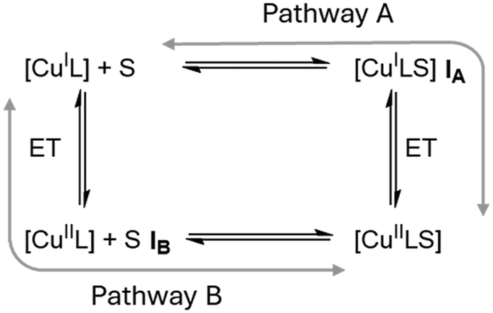
In 2019, however, Hagen hypothesized that the rigid entatic state might be of marginal existence in biological systems and proposed a wide distribution of possible coordination geometries, a so-called ecstatic state, to facilitate fast electron transfer.27 Instead of locking the coordination sphere in a rigid conformation, the ecstatic state lowers the reorganization energy by having a flexible ligand scaffold able to rapidly adopt the metal center's preferred coordination geometry. In accordance with this hypothesis, Aravena and Lemus et al. reported a group of copper complexes of tetradentate ligands whose electron transfer reactivity increases with the flexibility of the ligand scaffold.28 As an alternative to the ecstatic state, Hureau et al. described an “in-between” state of copper ions bound to flexible amyloid-β peptides.29 These can adopt discrete conformations that are similar for both product and reactant state, in turn enabling rapid electron transfer processes that lead to high oxidative stress in patients with neurodegenerative diseases. Recently, Olshansky et al. published several studies focusing on conformationally dynamic copper coordination compounds on the basis of tripodal ligand systems.30–33 Notably, the therein reported [CuCl(dpaSMe)]+/0 redox pair exhibits the highest self-exchange rate of any model system studied to date.31 Tripodal tetradentate ligand systems have been studied previously by Rorabacher et al. and Yandell et al. under the lens of the rigid entatic state, as they can neither adopt an ideal tetrahedral nor a square planar coordination geometry.34–36 They reported that the model systems experienced a change in coordination number (CN) upon oxidation by coordinating a previously dissociated halogenide or solvent molecule and observed rather slow electron self-exchange rates. Rorabacher et al. postulated that CN-variant tripodal systems could undergo electron transfer following one of two possible pathways, depicted in Scheme 1.37 Both discussed mechanisms involve an electron transfer and the change of CN as discrete chemical reactions. The electron transfer of pathway A is preceded by the change in CN, giving rise to a [CuIL(S)] intermediate (IA) before oxidation takes place. Pathway B begins with oxidation of the [CuIL] system to a tetradentate [CuIIL] system (IB), followed by a change in CN. Discussions of the electron transfer mechanism of CN-variant tripodal model systems therefore center around the question whether the co-ligand coordinates before or after the relevant redox reaction occurs. The change of CN in a Cu(I) system was regarded too sterically demanding and Intermediate IA too unstable by Rorabacher et al., therefore Pathway B was stated as preferred in the oxidation reaction for a majority of tripodal model systems.37 The rapid electron transfer of model systems with similar tripodal ligands recently reported by Olshansky's group, however, suggests that the reaction mechanism of the older systems needs to be elucidated further to sufficiently explain their low rate constants. With the motivation to better understand the slow electron transfer of some CN-variant model systems of tripodal ligands, in our study, we discuss a set of tetradentate triarylamine ligands featuring guanidine and 2-methylquinolinyl groups in varying numbers. When these ligands form complexes with Cu(I) salts, their crystal structures are alike and show an uncommon umbrella-distortion. Despite the structural similarities observed among the Cu(I) complexes of these ligand systems, there is a substantial difference in the observed self-exchange reaction rates. These vary across four orders of magnitude and are inversely proportional to the number of guanidine units present within the ligand structure.
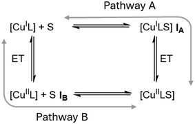 |
| | Scheme 1 Possible reaction pathways for CN-variant copper complexes as proposed by Rorabacher et al. with S demarking the external co-ligand.37 | |
Results and discussion
Ligand synthesis
The ligands were synthesized according to the reactions depicted in Scheme 2. The initial SNAr-reaction to tris(2-nitrophenyl)amine was performed according to a slightly modified procedure by Gorvin.38 The obtained nitro precursor was then reduced following a modified procedure described by Stavropoulos and Cronin et al. to obtain N1,N1-bis(2-aminophenyl)benzene-1,2-diamine.39 The amine precursor was then functionalized with two different Vilsmeier salts (DMEG: dimethylethyleneguanidino and TMG: tetramethylguanidino) to yield ligand pair L1. To obtain pairs L2 and L3, the amine precursor was first subjected to a Doebner–Miller reaction in a procedure inspired by Dalko et al., followed by a separation of the products via gradient column-chromatography.40 A subsequent functionalization with each precursor and the TMG- and DMEG-Vilsmeier salts was performed to yield the corresponding ligand pairs.
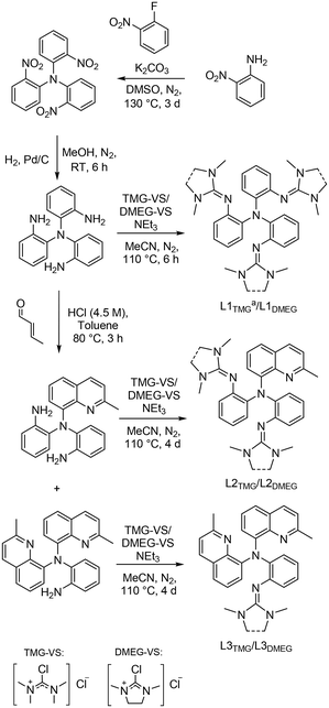 |
| | Scheme 2 Employed synthesis routes for the reported ligand systems. a: L1TMG has been synthesized previously by Stavropoulos and Cronin et al.39 | |
Cu(I)-complex synthesis and structural characterization
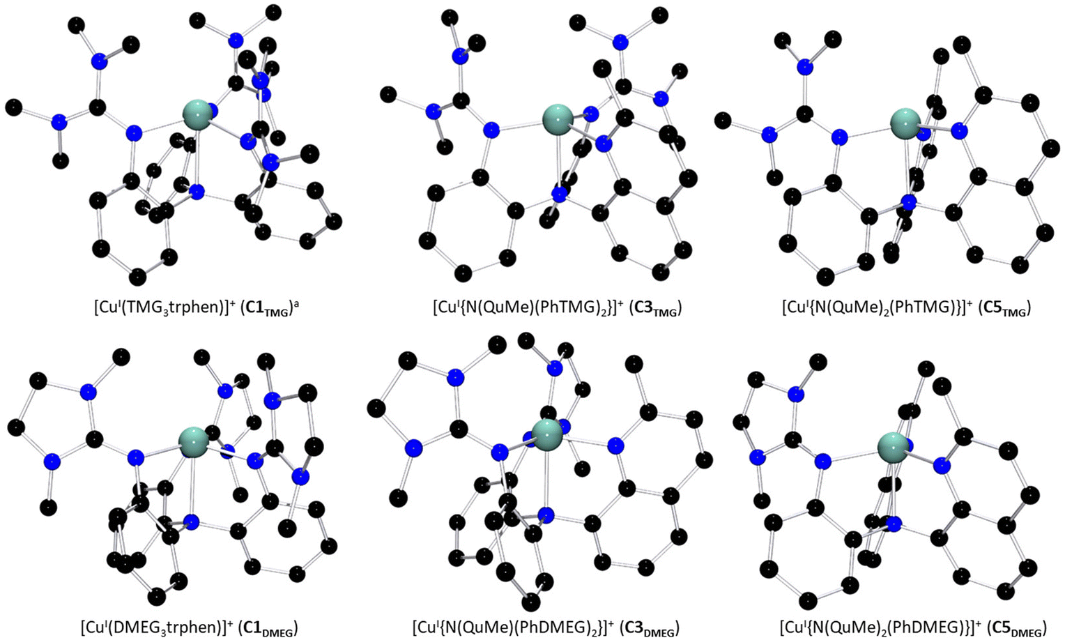
All six ligands were consequently combined with [CuI(MeCN)4]PF6 to yield three pairs of complexes, [CuITMG3trphen]PF6 (C1TMG)39 and [CuIDMEG3trphen]PF6 (C1DMEG), [CuI{N(QuMe)(PhTMG)2}]PF6 (C3TMG) and [CuI{N(QuMe)(PhDMEG)2}]PF6 (C3DMEG) as well as [CuI{N(QuMe)2(PhTMG)}]PF6 (C5TMG) and [CuI{N(QuMe)2(PhDMEG)}]PF6 (C5DMEG).
The complex cations’ solid state structures, including the C1TMG structure published by Stavropoulos and Cronin et al., are depicted in Fig. 1.39C3TMG was crystallized by dissolving the Cu(I) salt and the ligand L2TMG in acetonitrile or layering the dissolution with diethyl ether. The solid state structure of C5TMG was obtained in a similar fashion out of a dichloromethane solution layered with pentane. C1DMEG and C3DMEG were both synthesized and precipitated before being crystallized analogously to C3TMG. C5DMEG was crystallized from a dissolution of the pre-synthesized complex in dichloromethane layered with pentane. Selected bond lengths, angles, and structure parameters of the six structures are listed in Table 1. The Cu(I) complex cations display a four-coordinate coordination geometry best described as a distorted trigonal pyramid, a so-called umbrella-distortion, in which the copper ion is not positioned at the center, but slightly outside the face of the coordination-polyhedron.41 This distortion becomes less pronounced with an increasing number of quinolinyl donors, as can be seen by the shortening Cu–NAm bond length and increasing N(1)–Cu–N(X) angles. Umbrella-distortions are relatively uncommon among Cu complexes as stated by Alvarez et al.41 In the present systems, they likely are caused by the interplay of the ligand scaffold's rigid aromatic backbone, the fact that arylamines are known to be poor donors and the strong π-donor properties of the guanidine donors.17,42 The general coordination geometry is similar for each complex cation, however. While the apparent coordination geometry seems to allow for a fifth donor in form of a coordinating solvent molecule like acetonitrile, no signs of a pentacoordinate [CuI(L)(MeCN)]+ species were observed in either the crystal data, NMR spectra, or mass spectra. This is not unusual for Cu(I) complexes of tripodal ligands, as reported by Rorabacher et al.36,37
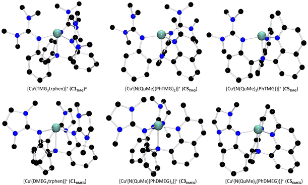 |
| | Fig. 1 Molecular structures of the Cu(I) complex cations of both guanidine variants of C1 to C5 in the solid state. H atoms, non-coordinating anions and solvent molecules have been omitted for clarity. a: Crystal structure was reported by Stavropoulos and Cronin et al.39 | |
Table 1 Key bond lengths, bond angles and structure parameters of the Cu(I) complex cations C1, C3 and C5
| |
C1TMG
|
C1DMEG
|
C3TMG
|
C3DMEG
|
C5TMG
|
C5DMEG
|
Crystal structure was reported by Stavropoulos and Cronin et al.39
ρ = 2a/(b + c) with a = d(CGua–NGua), b = d(CGua–Namine,1) and c = d(CGua–Namine,2).48
 .8 .8
|
| Bond lengths [Å] |
| Cu–NAm(1) |
2.355(2) |
2.3475(19) |
2.275(3) |
2.282(2) |
2.254(2) |
2.2608(16) |
| Cu–NGua(2) |
2.0129(15) |
2.0299(11) |
|
|
|
|
| Cu–NGua(3) |
2.0129(15) |
2.0299(11) |
2.051(3) |
1.982(2) |
|
|
| Cu–NGua(4) |
2.0129(15) |
2.0299(11) |
1.974(3) |
2.068(2) |
1.991(2) |
2.0373(13) |
| Cu–NQu(2) |
|
|
1.971(3) |
1.9735(19) |
1.982(2) |
2.0135(13) |
| Cu–NQu(3) |
|
|
|
|
2.041(2) |
1.9512(13) |
| Bond angles [°] |
| N(1)–Cu–N(2) |
78.54(4) |
78.46(3) |
82.24(12) |
81.78(8) |
83.29(9) |
81.61(6) |
| N(1)–Cu–N(3) |
78.54(4) |
78.46(3) |
79.22(13) |
78.17(9) |
80.28(9) |
82.27(5) |
| N(1)–Cu–N(4) |
78.54(4) |
78.46(3) |
87.87(12) |
81.87(8) |
81.49(9) |
79.54(5) |
| N(2)–Cu–N(3) |
116.15(3) |
116.10(2) |
131.67(13) |
100.89(8) |
111.92(9) |
124.01(5) |
| N(2)–Cu–N(4) |
116.15(3) |
116.10(2) |
113.22(13) |
130.00(8) |
129.68(10) |
102.01(5) |
| N(3)–Cu–N(4) |
116.15(3) |
116.10(2) |
107.48(14) |
121.22(8) |
112.23(9) |
126.87(5) |
| Structural parameters |
|
ρ
|
0.96, 0.96, 0.96 |
0.95, 0.95, 0.95 |
0.96, 0.97 |
0.96, 0.96 |
0.97 |
0.96 |
|
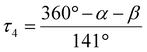
τ
4
|
0.91 |
0.91 |
0.81 |
0.77 |
0.84 |
0.77 |
|
S(Td) |
6.462 |
6.622 |
6.130 |
6.451 |
5.754 |
6.210 |
|
S(D4h) |
36.775 |
36.820 |
32.625 |
33.935 |
33.054 |
32.793 |
|
S(C3v) |
0.819 |
0.818 |
1.006 |
1.299 |
0.733 |
1.128 |
Using the SHAPE-program by Alvarez et al., the coordination geometries’ distortion away from either an ideal square planar (D4h), tetrahedral (Td) or square pyramidal (C3v) symmetries were assessed listed in Table 1.41 The coordination environments of all Cu(I)-structures again display similar values, with strong distortions away from the Td and D4h symmetries and the least distortion away from C3v symmetry.The computationally obtained structures for the solvated ions are in good agreement with the observed solid state structures (see ESI†).
Computational assessment of the Cu(II) complex cations
Stavropoulos and Cronin et al. published a Cu(II) solid state structure for C2TMG.39 Any attempts made to obtain a Cu(II) structure of the novel ligands proved to be unsuccessful for reasons including but not limited to possible decay of the Cu(II) systems (see ESI†). Thus, their structures were simulated in solution via density functional theory (DFT) computations. The possibility of a stable four-coordinate Cu(II) species was ruled out via isodesmic calculations which show that a pentacoordinate state is universally preferred (see ESI†). The substitution pattern of the ligands in combination with an added acetonitrile molecule as co-ligand allow for up to four different conformers of pentacoordinate Cu(II) complex cations in solution, depicted in Fig. 2(a). These four conformers can be divided into two separate pairs. One pair has the aryl amine donor (NAm) coordinating the metal center at a basal position of the resulting square pyramid, the other pair has it coordinating the metal center at the apical position of the pyramid. These basal and apical pairs can be subdivided further by the arrangement of the ligands’ different arms relative to the co-ligand.
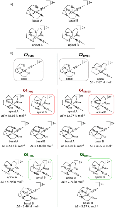 |
| | Fig. 2 (a) Schematic representation of the possible conformers for C2, C4 and C6. For C2TMG and C2DMEG, the corresponding A and B conformers are identical. (b) Schematic depiction of the conformers of each derivative of the complex cations C2, C4 and C6via DFT structure optimization. The framed structures represent the lowest lying conformer of each species, the difference in energy (ΔE) of each other conformer relative to the framed one is noted below its schematic structure. If certain structures are not depicted, they could not be found via the employed methods (TPSSh/def2-TZVP and PCM solvent model for acetonitrile and empirical dispersion with BECKE-JOHNSON dampening). | |
In Fig. 2(b), the found conformers of each Cu(II) species, as well as their relative difference in electronic energy are depicted. It is noticeable that the C2 complex cations show either exclusively one basal conformer (C2TMG) or energetically prefer the basal conformer over the apical one (C2DMEG). Contrary to this, the pairs of C4 and C6 with the less bulky ligands prefer the apical B conformer over any other possible conformation. The observed relative differences in energy are generally small with an overall range of 7.7 to 2.1 kJ mol−1. Outliers are the apical A conformers of the C2TMG and C2DMEG pair, both sitting at a much higher energies relative to the lowest conformer. Given the small differences in energy between each conformer, it is reasonable to assume that the Cu(II) species exist in a dynamic equilibrium.
Assessment of electron transfer properties
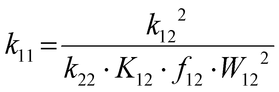
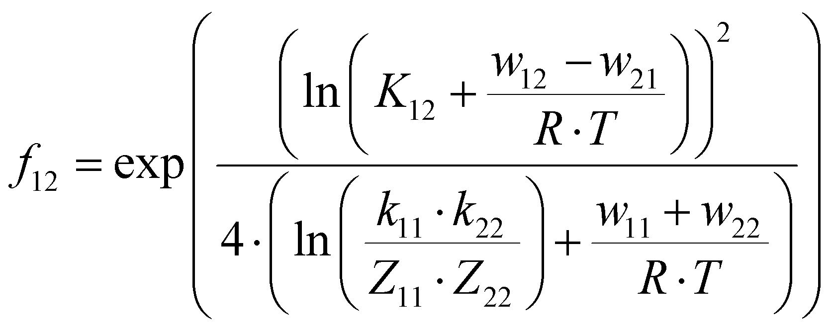
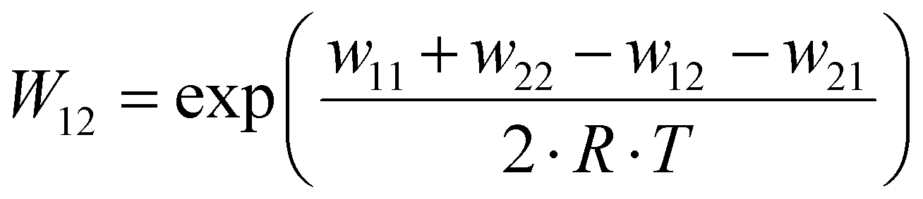
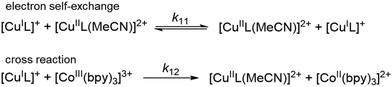
The electron self-exchange rates k11 were obtained via application of the Marcus cross-relation, which is derived from the Marucs theory describing the outer-sphere mechanism of electron transfer reactions (eqn (1)–(4)).43,44| | 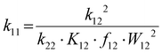 | (1) |
| |  | (2) |
| |  | (3) |
| |  | (4) |
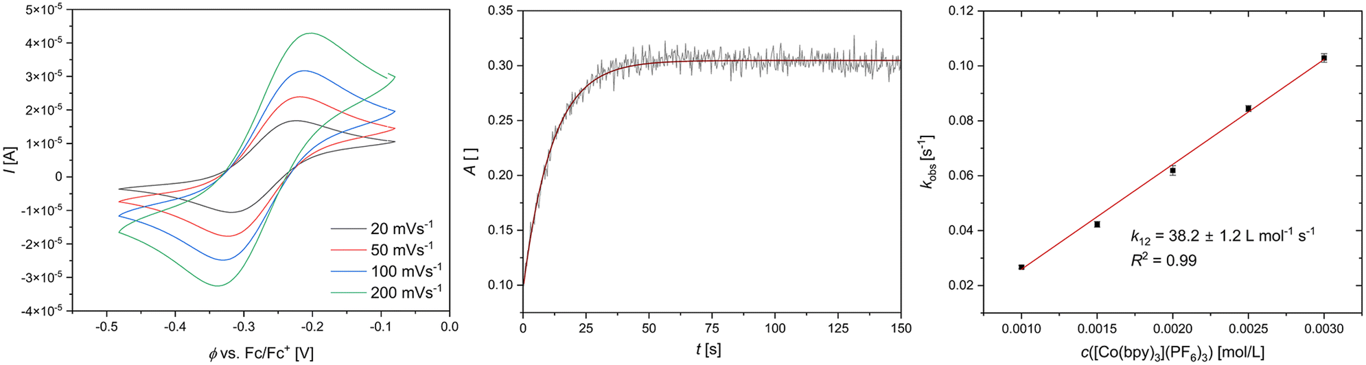
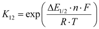
k11 was calculated viaeqn (1), requiring the experimentally determined reaction rate k12 and equilibrium constant K12 (eqn (2)), the correction term f12 (eqn (3)), the work term W12 (eqn (4)) and the electron self-exchange rate k22 of the employed counter complex redox couple [Co(bpy)3]2+/3+. The latter was used as reported in acetonitrile at 298 K.45 The equilibrium constant K12 depends on difference of the redox potentials, ΔE1/2, of the counter complex redox couple and the investigated copper complex redox couple (eqn (2)). The required E1/2 of the copper complexes were measured beginning from the Cu(I) species via cyclic voltammetry in acetonitrile at 25 °C. The cyclic voltammetry yielded quasi-reversible redox waves for each redox pair (see Fig. 3 for R1TMG as an example or Fig. S1 to S5 in ESI†), the potentials of which are more negative with an increasing number of guanidine donors present in the ligand scaffolding (see Table 2). k12 was determined by monitoring the cross-reaction depicted in Scheme 3 at 298 K using stopped-flow UV/Vis spectroscopy for five distinct counter complex concentrations. Each concentration was in excess to the Cu(I) complexes present, rendering the cross-reaction a reaction pseudo-first order. The influence of the ionic strength on the activity coefficients of the reactants was not considered (further information see ESI†). For each concentration, the increase or decrease of distinct absorption bands was plotted against time, fitted and the resulting apparent reaction rates were plotted against the counter complex concentration. Lastly, k12 was obtained as the slope of the linear regression from the resulting plot, as depicted exemplary for R1TMG in Fig. 4. The relevant experimental data as well as the calculated self-exchange rates k11 for each redox pair are listed in Table 2.
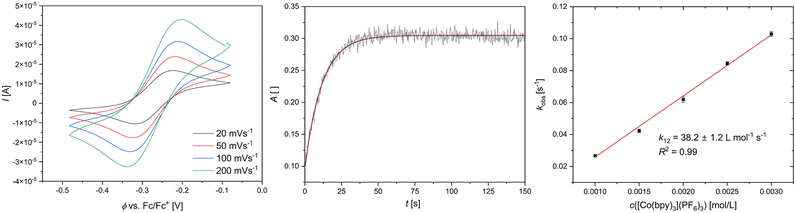 |
| | Fig. 3 Left: cyclic voltammogram of R1TMG starting from C1TMG (c = 10−3 M) in MeCN with [NBu4][PF6] (c = 0.1 M). Middle: exponential decay fit of the increase of a Cu(II) absorption band from R1TMG during a cross reaction. Right: Plot of the reaction rate kobs against the concentration of [Co(bpy)3]3+ for R1TMG. | |
 |
| | Scheme 3 Illustration of the electron self-exchange of the Cu redox couples and of the cross reaction of the Cu(I) complexes with the counter complex [Co(bpy)3]3+. | |
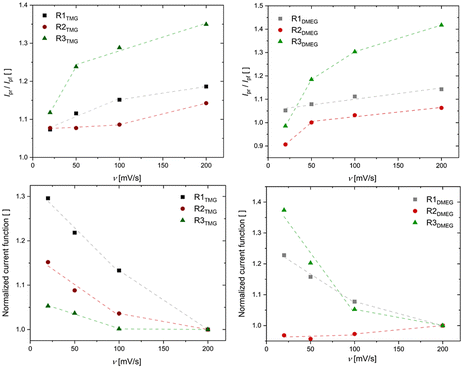 |
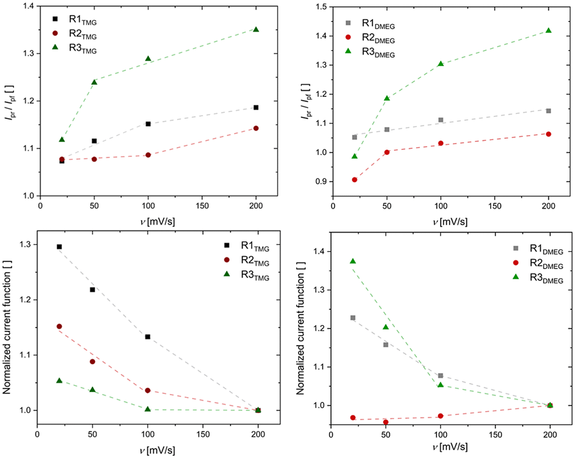
| | Fig. 4 Above: current ratios of designated redox pairs plotted against the scan rate v. Below: normalized current functions of designated redox pairs plotted against the scan rate v. The lines solely serve as guides to the eyes. | |
Table 2 Redox potentials E1/2 differences between the redox potentials of the copper redox couple and the counter complex ΔE1/2, equilibrium constants K12, reaction rates k12 and electron self-exchange rates k11
| |
E
1/2 [V] vs. Fc/Fc+ |
ΔE1/2 [V] |
K
12 [ ] |
k
12 [L mol−1 s−1] |
k
11 [L mol−1 s−1] |
|
Procedure for measuring k12 deviated from other systems due to optical interference of the counter complex.
|
|
R1TMG
|
−0.27 |
0.22 |
4.29 × 10³ |
(3.82 ± 0.12) × 101 |
(3.13 ± 0.20) × 10−1 |
|
R1DMEG
|
−0.26 |
0.20 |
2.83 × 10³ |
(1.30 ± 0.05) × 101 |
(5.49 ± 0.43) × 10−2 |
|
R2TMG
|
−0.20 |
0.14 |
2.29 × 10² |
(1.11 ± 0.31) × 101 |
(4.03 ± 0.23) × 10−1 |
|
R2DMEG
|
−0.18 |
0.13 |
1.83 × 10² |
(1.54 ± 0.13) × 101 |
(9.72 ± 1.7) × 10−1 |
|
R3TMG
|
−0.07 |
0.02 |
1.97 |
3.50 ± 0.01 |
4.26 ± 0.03 |
|
R3DMEG
|
−0.06 |
0.01 |
1.16 |
(1.03 ± 0.64) × 101 |
(6.29 ± 0.81) × 101 |
The span of electron self-exchange rates over four orders of magnitude contrasts with the overall similar Cu(I) and Cu(II) coordination geometries, raising questions regarding the prevalent reaction mechanism (vide supra, Scheme 1). Since Pathway B is considered the favored pathway, it was investigated first.37 The examination of this pathway for the herein discussed systems was performed by DFT computation of the outer- and inner-sphere reorganization energies of the involved four-coordinate [CuI/IIL] redox couples via Nelsen's four-point method (see Table 3 and ESI for further info†).20,26,46 All reorganization energies were computed on the assumption that a unitary reaction pathway is followed for oxidation and reduction. The obtained λ11 values are approximately in the same range as the ones for TMGqu-derived systems reported by our group, the latter displaying self-exchange rates two orders of magnitudes higher than the fastest system in this work.20 Further, the trend for the obtained reorganization energies does not match the trend for obtained k11 values. Both findings suggest that, for Pathway B to be preferred, the association of the acetonitrile co-ligand must have a major influence on the reaction kinetics. To test for this possibility, the kinetic barriers for this coordination were calculated using DFT-computations. The conducted computations for varying the NMeCN Cu distance proved to be challenging and succeeded only for some discussed Cu(II)-systems. They all, however, show a barrierless transition from a four-coordinate [CuIIL] system to the five-coordinate [CuIILS] derivatives. Both theoretical findings cast doubt on the idea of Pathway B being the prevalent reaction mechanism. Experimental data of the systems’ behavior upon oxidation was collected from CV measurements by plotting the current ratio Ipr/Ipf and the current function Ipf/v1/2 against v, with Ipf being the forward (oxidation) current, Ipr the reverse (reduction) current and v being the applied scan rate (see Fig. 4).47 A reaction occurring after a redox process like in Pathway B would be expected to show a value <1 for Ipr/Ipf. The ratio should decrease with scan rate, as the species responsible for the reverse current can form to a lesser extent. Further, the observed current function Ipf /v1/2 should be nearly invariant to the scan rate. All systems’ cyclic voltammograms show a current ratio that increases with the scan rate. Further, it can be observed that the current function decreases with the scan rate for all systems except R2DMEG. The reason as to why the current function of R2DMEG deviates from the pattern established by the remaining five redox couples is unknown. The combination of the current ratio increasing from <1 with a slightly increasing current function possibly suggests a combination of a CN change prior to the electron transfer step with a successive, irreversible reaction of the Cu(II) species to an unknown decay product.47 The observed behavior therefore implies a fast decay of C4DMEG compared to that of other herein discussed Cu(II) species. Alternative explanations for this deviation from the established trend cannot be ruled out, however. The observed patterns of the cyclic voltammetry data indicate a significant structural rearrangement or a reaction to take place before the oxidation reaction occurs, as it would be expected for Pathway A.47 The four-coordinate [CuIL] systems therefore acquire an acetonitrile co-ligand from solution before they undergo the actual electron transfer step. It follows that the observed self-exchange kinetics can only be sufficiently explained by also considering the rate and equilibrium constants of intermediate IA's formation starting from the [CuIL] species (see Scheme 4). To test this possibility of a gated electron transfer, the equilibrium constant Ka of all Cu(I) systems at standard conditions were calculated using the differences in free energy between the tetra- and pentacoordinate Cu(I) systems computed via DFT calculations (see Table 4 and ESI†). The obtained equilibrium constants correlate with the observed k11, decreasing significantly with respect to the guanidine moieties present which could reasonably be attributed to the steric bulk of the functional group. The increased steric bulk therefore influences the stability of intermediate IA and therefore diminishes the observed reaction rate. This is further underscored by the differences in Ka between TMG and DMEG units. This correlation indicates a gated electron transfer pathway which would obscure the actual electron transfer kinetics of the successive reaction and therefore prohibits an assessment of the structural influence of the ligands on the electron transfer reaction.
 |
| | Scheme 4 Schematic illustration of important reaction parameters (above the arrows) that influence the determined self-exchange rate k11. S demarks an external co-ligand, Ka represents the equilibrium constant of the formation of species IA, ka represents its reaction rate and kET represents the reaction rate of the electron self-exchange reaction. | |
Table 3 Inner (λ11,I), outer (λ11,S) and the total sum of both reorganization energies (λ11,T) for each redox couple
| |
λ
11,I [kJ mol−1] |
λ
11,S [kJ mol−1] |
λ
11,T [kJ mol−1] |
|
R1TMG
|
54.4 |
129.8 |
184.2 |
|
R1DMEG
|
64.3 |
129.6 |
193.9 |
|
R2TMG
|
48.1 |
133.4 |
181.5 |
|
R2DMEG
|
58.8 |
133.7 |
192.5 |
|
R3TMG
|
53.8 |
136.6 |
190.5 |
|
R3DMEG
|
65.7 |
136.9 |
202.5 |
Table 4 Difference in free enthalpy and the resulting equilibrium constants Ka as well as the corresponding decadic logarithm for each investigated redox pair. The pentacoordinate [Cu(I)LS] species was set as the product of the reaction
| |
ΔG [kJ mol−1] |
K
a [ ] |
lg (Ka) [ ] |
|
R1TMG
|
20.31 |
2.8 × 10⁻⁴ |
−3.6 |
|
R1DMEG
|
−1.82 |
2.1 |
3.2 × 10⁻¹ |
|
R2TMG
|
−9.00 |
3.8 × 101 |
1.6 |
|
R2DMEG
|
−9.30 |
4.3 × 101 |
1.6 |
|
R3TMG
|
−11.62 |
1.1 × 10² |
2.0 |
|
R3DMEG
|
−12.71 |
1.7 × 10² |
2.2 |
An explanation for the preference of an initial CN-change to intermediate IA over a direct oxidation to intermediate IB is found in the previously discussed umbrella distortion of the [CuIL] systems. This feature is not as pronounced or absent in aliphatic tripodal ligand systems that conform to Pathway B.35,37 The weakened NAm–Cu coordinative bonds in these distorted structures destabilize the tetra-coordinate [CuIIL] intermediates IB of the competing pathway, leading to Pathway A to be preferred by the studied systems.
Conclusion
In this study, we discussed a set of tripodal tetradentate triarylamine ligands featuring guanidine and 2-methylquinolinyl groups. The obtained molecular structure in the soilid state of the Cu(I) complex cations show trigonal pyramidal coordination geometries in an uncommon umbrella-distortion. The Cu(II) structures were simulated using DFT calculations and suggest a change in coordination number compared to their Cu(I) pendants by association of a co-ligand as well as a variety of conformers that likely co-exist in thermal equilibrium. Despite the structural similarities observed among the Cu(I) complexes, their electron self-exchange rates vary across four orders of magnitude and are inversely proportional to the number of guanidine units present within the ligand structure. An investigation of the prevalent reaction mechanism for the electron transfer with DFT calculations and cyclic voltammetry showed that the oxidation-addition mechanism preferred by Rorabacher et al. is likely not prevalent, with an inverse addition-oxidation pathway being present. This subversion of the expected behavior likely stems from the observed umbrella distortion of the Cu(I) structures, destabilizing the necessary Cu(II) intermediate of the oxidation-addition pathway. This shows that it is possible to influence the electron transfer mechanism of CN-variant model systems by molecular design. Based on our findings, the kinetic and thermodynamic constants of the initial addition step influence the observed electron self-exchange rates and therefore prohibit any discussion of structural influence on the oxidation step. Further studies of CN-variant tripodal triaryl ligands as model complexes for electron transfer proteins should therefore consider including a fifth donor in the ligand scaffolding as this would eliminate the kinetic barriers that arise from co-ligand dissociation and association. Systems incorporating weak arylamine bridgehead donors would be similar to the glycoligands reported by Policar et al. with the added benefit of a flexible inner coordination sphere.24 However, copper complexes of tripodal pentadentate arylamine ligands have yet to be implemented in electron transfer studies.
Data availability
The experimental data of the methods and details of the synthesis with characterization have been included as part of the ESI. Crystallographic data have been deposited CCDC 2382527 for C1DMEG, CCDC 2382528 for C3TMG, CCDC 2382529 for C3DMEG, CCDC 2382530 for C5TMG and CCDC 2382531 for C5DMEG.† Additional information on the synthesis of the target compounds and original analysis data files are available in the Chemotion repository (https://dx.doi.org/10.14272/collection/ToS_2024-10-09) and the RADAR4Chem repository (DOI: 10.22000/snmphx276tt041sa and direct link https://www.radar-service.eu/radar/en/dataset/snmphx276tt041sa?token=QwPxHaoRvtRHZDfFgQFZ).
Conflicts of interest
There are no conflicts to declare.
Acknowledgements
S. H.-P. acknowledges financial support by the Deutsche Forschungsgemeinschaft (DFG, 413524714). We thank the Regional Computing Center of the University of Cologne (RRZK) for providing computing time on the DFG-funded High Performance Computing (HPC) system CHEOPS as well as support. Moreover, we thank NFDI4Chem for support with data sharing in the Chemotion and RADAR4Chem repositories.
References
- J. Liu, S. Chakraborty, P. Hosseinzadeh, Y. Yu, S. Tian, I. Petrik, A. Bhagi and Y. Lu, Chem. Rev., 2014, 114, 4366–4369 CrossRef CAS.
- E. I. Solomon, D. E. Heppner, E. M. Johnston, J. W. Ginsbach, J. Cirera, M. Qayyum, M. T. Kieber-Emmons, C. H. Kjaergaard, R. G. Hadt and L. Tian, Chem. Rev., 2014, 114, 3659–3853 CrossRef CAS.
- M. R. Redinbo, T. O. Yeates and S. Merchant, J. Bioenerg. Biomembr., 1994, 26, 49–66 CrossRef CAS PubMed.
- C. Buning, G. W. Canters, P. Comba, C. Dennison, L. Jeuken, M. Melter and J. Sanders-Loehr, J. Am. Chem. Soc., 2000, 122, 204–211 CrossRef CAS.
- S. Suzuki, K. Kataoka, K. Yamaguchi, T. Inoue and Y. Kai, Coord. Chem. Rev., 1999, 190–192, 245–265 CrossRef CAS.
- F. A. Armstrong, P. C. Driscoll, H. Allen and O. Hill, FEBS Lett., 1985, 190, 242–248 CrossRef CAS.
- S. Dahlin, B. Reinhammar and M. T. Wilson, Biochem. J., 1984, 218, 609–614 CrossRef CAS PubMed.
- L. Yang, D. R. Powell and R. P. Houser, J. Chem. Soc., Dalton Trans., 2007, 955–964 RSC.
-
R. R. Conry, Encycl. Inorg. Chem, 2006 Search PubMed.
- B. L. Vallee and R. J. Williams, Proc. Natl. Acad. Sci. U. S. A., 1968, 59, 498–505 CrossRef CAS.
- B. G. Karlsson, R. Aasa, B. G. Malmstroem and L. G. Lundberg, Chalmers Tek. Hogsk. Doktorsavhandlingar, 1993, 253, 99–102 Search PubMed.
- B. G. Malmstrom, Eur. J. Biochem., 1994, 718, 711–718 CrossRef PubMed.
- M. H. M. Olsson, U. Ryde, B. O. Roos and K. Pierloot, J. Biol. Inorg. Chem., 1998, 3, 109–125 CrossRef CAS.
- B. Xie, T. Elder, L. J. Wilson and D. M. Stanbury, Inorg. Chem., 1999, 38, 12–19 CrossRef CAS.
- B. Xie, L. J. Wilson and D. M. Stanbury, Inorg. Chem., 2001, 40, 3606–3614 CrossRef CAS.
- A. Hoffmann, S. Binder, A. Jesser, R. Haase, U. Flörke, M. Gnida, M. Salomone Stagni, W. Meyer-Klaucke, B. Lebsanft, L. E. Grünig, S. Schneider, M. Hashemi, A. Goos, A. Wetzel, M. Rübhausen and S. Herres-Pawlis, Angew. Chem., Int. Ed., 2014, 53, 299–304 CrossRef CAS.
- E. W. Dahl and N. K. Szymczak, Angew. Chem., Int. Ed., 2016, 55, 3101–3105 CrossRef CAS.
- A. Hoffmann, J. Stanek, B. Dicke, L. Peters, B. Grimm-Lebsanft, A. Wetzel, A. Jesser, M. Bauer, M. Gnida, W. Meyer-Klaucke, M. Rübhausen and S. Herres-Pawlis, Eur. J. Inorg. Chem., 2016, 2016, 4731–4743 CrossRef CAS.
- D. F. Schrempp, S. Leingang, M. Schnurr, E. Kaifer, H. Wadepohl and H. J. Himmel, Chem. – Eur. J., 2017, 23, 13607–13611 CrossRef CAS.
- J. Heck, F. Metz, S. Buchenau, M. Teubner, B. Grimm-Lebsanft, T. P. Spaniol, A. Hoffmann, M. A. Rübhausen and S. Herres-Pawlis, Chem. Sci., 2022, 13, 8274–8288 RSC.
- G. Chaka, J. L. Sonnenberg, H. B. Schlegel, M. J. Heeg, G. Jaeger, T. J. Nelson, L. A. Ochrymowycz and D. B. Rorabacher, J. Am. Chem. Soc., 2007, 129, 5217–5227 CrossRef CAS PubMed.
- P. Comba and W. Schiek, Coord. Chem. Rev., 2003, 238–239, 21–29 CrossRef CAS.
- P. Comba, M. Kerscher and A. Roodt, Eur. J. Inorg. Chem., 2004, 4640–4645 CrossRef CAS.
- L. Garcia, F. Cisnetti, N. Gillet, R. Guillot, M. Aumont-Nicaise, J. P. Piquemal, M. Desmadril, F. Lambert and C. Policar, J. Am. Chem. Soc., 2015, 137, 1141–1146 CrossRef CAS PubMed.
- C. I. Ii, C. Cuiu, D. K. Coggin, J. A. González, A. M. Kook, C. Bergman, T. D. Brennan, W. R. Scheldt, D. M. Stanbury and L. J. Wilson, Inorg. Chem., 1991, 1125–1134 Search PubMed.
- J. Stanek, N. Sackers, F. Fink, M. Paul, L. Peters, R. Grunzke, A. Hoffmann and S. Herres-Pawlis, Chem. – Eur. J., 2017, 23, 15738–15745 CrossRef CAS.
- W. R. Hagen, Metallomics, 2019, 11, 1768–1778 CrossRef CAS PubMed.
- L. Llanos, C. Vera, A. Vega, D. Aravena and L. Lemus, Inorg. Chem., 2020, 59, 15061–15073 CrossRef CAS.
- E. Falcone and C. Hureau, Chem. Soc. Rev., 2023, 52, 6595–6600 RSC.
- P. J. Griffin, B. J. Charette, J. H. Burke, J. Vura-Weis, R. D. Schaller, D. J. Gosztola and L. Olshansky, J. Am. Chem. Soc., 2022, 144, 12116–12126 CrossRef CAS PubMed.
- P. J. Griffin and L. Olshansky, J. Am. Chem. Soc., 2023, 145, 20158–20162 CrossRef CAS PubMed.
- P. J. Griffin, M. J. Dake, A. D. Remolina and L. Olshansky, Dalton Trans., 2023, 8376–8383 RSC.
- B. J. Charette, P. J. Griffin, C. M. Zimmerman and L. Olshansky, Dalton Trans., 2022, 6212–6219 RSC.
- K. D. Karlin and J. K. Yandell, Inorg. Chem., 1984, 1184–1188 CrossRef CAS.
- E. A. Ambundo, L. A. Ochrymowycz and D. B. Rorabacher, Inorg. Chem., 2001, 40, 5133–5138 CrossRef CAS PubMed.
- D. B. Rorabacher, Chem. Rev., 2004, 104, 651–697 CrossRef CAS.
- E. A. Ambundo, Q. Yu, L. A. Ochrymowycz and D. B. Rorabacher, Inorg. Chem., 2003, 42, 5267–5273 CrossRef CAS.
- J. H. Gorvin, J. Chem. Soc., Perkin Trans., 1988, 1, 1331–1335 RSC.
- V. Bagchi, P. Paraskevopoulou, P. Das, L. Chi, Q. Wang, A. Choudhury, J. S. Mathieson, L. Cronin, D. B. Pardue, T. R. Cundari, G. Mitrikas, Y. Sanakis and P. Stavropoulos, J. Am. Chem. Soc., 2014, 136, 11362–11381 CrossRef CAS.
- P. Dunkel, M. Petit, H. Dhimane, M. Blanchard-Desce, D. Ogden and P. I. Dalko, ChemistryOpen, 2017, 6, 660–667 CrossRef CAS PubMed.
- J. Cirera, P. Alemany and S. Alvarez, Chem. – Eur. J., 2004, 10, 190–207 CrossRef CAS.
- S. Wörl, D. Hellwinkel, H. Pritzkow, M. Hofmann and R. Krämer, Dalton Trans., 2004, 2750–2757 RSC.
- R. A. Marcus and N. Sutin, Biochim. Biophys. Acta, 1984, 811, 265–322 CrossRef.
-
L. H. Gade, Koordinationschemie, Wiley-VCH, Weiheim, New York, Chichester, Brisbane, Singapore, Toronto, 1., 1998 Search PubMed.
- B. C. Dunn, L. A. Ochrymowycz and D. B. Rorabacher, Inorg. Chem., 1995, 34, 1954–1956 CrossRef CAS.
- J. Stanek, M. Konrad, J. Mannsperger, A. Hoffmann and S. Herres-Pawlis, Eur. J. Inorg. Chem., 2018, 2018, 4997–5006 CrossRef CAS.
-
P. Zanello and N. G. Connelly, Voltammetric techniques, 2007 Search PubMed.
- V. Raab, K. Harms, J. Sundermeyer, B. Kovačević and Z. B. Maksić, J. Org. Chem., 2003, 68, 8790–8797 CrossRef CAS.
Footnote |
| † Electronic supplementary information (ESI) available: Experimental data of the methods and details of the synthesis with characterization (NMR and IR spectroscopy and mass spectrometry), crystallographic information, UV/Vis-spectra, CVs and stopped-flow UV/Vis spectra, DFT details, NMR spectra, additional plots and further discussions. CCDC 2382527–2382531. For ESI and crystallographic data in CIF or other electronic format see DOI: https://doi.org/10.1039/d4dt02917h |
|
| This journal is © The Royal Society of Chemistry 2025 |
Click here to see how this site uses Cookies. View our privacy policy here. 
 Open Access Article
 This Open Access Article is licensed under a
  ,
Marcel
Walbeck
,
Alexander
Hoffmann
,
Marcel
Walbeck
,
Alexander
Hoffmann

 .8
.8