
 Open Access Article
 This Open Access Article is licensed under a
 Creative Commons Attribution 3.0 Unported Licence
Solute dispersion in pre-turbulent confined active nematics†
Tomás Alvim ab,
Margarida M. Telo da Gamaab and
Rodrigo C. V. Coelho*ab
ab,
Margarida M. Telo da Gamaab and
Rodrigo C. V. Coelho*ab
aCentro de Física Teórica e Computacional, Faculdade de Ciências, Universidade de Lisboa, 1749-016 Lisboa, Portugal. E-mail: rcvcoelho@fc.ul.pt
bDepartamento de Física, Faculdade de Ciências, Universidade de Lisboa, P-1749-016 Lisboa, Portugal
First published on 13th February 2025
Abstract
We investigate the dispersion of solutes in active nematic fluids confined to narrow channels based on simulations of nematohydrodynamics. The study focuses on two pre-turbulent regimes: oscillatory flow, with net mass flux, and dancing flow, without net flux. Non-diffusive tracers exhibit markedly different behaviors in oscillatory and dancing flows. By contrast, the hydrodynamic dispersion of solutes driven by active flows, both in the oscillatory and dancing flows, are similar and can be described by an extension of the Taylor–Aris law. This study contributes to our understanding of micromixing in active flows both in nature and in applications.
I Introduction
Metabolic and biological processes rely on the consumption and release of molecules, which become dispersed throughout the surrounding fluid. The presence of fluid currents influences the spatial distribution of the dissolved molecules, which governs their local concentrations and thus their effects on biological processes. Fluids confined to channels are a common scenario, both in natural environments, such as porous media like soil,1 and in engineered systems, such as lab-on-a-chip devices.2 In these settings, fluid flow and the resultant solute transport are strongly affected by the fluid's confinement and state with emphasis on its activity.A physical model that describes many aspects of the self-generated active flows is nematohydrodynamics with non-equilibrium stresses that couple linearly the activity to the orientational order3 as the dominant far-field contribution of a microswimmer to the velocity field typically resembles that of a force dipole, apolar at the microscale. Theoretical analysis of tracer dispersion in suspensions of decorrelated squirming microswimmers predicts an enhanced diffusivity proportional to both the self-propulsion velocity and the number density of microswimmers.4 Experimental studies of tracer dispersion in mesoscale turbulence report a dispersion coefficient proportional to the swimmer density.5,6 The density of the swimmers and their self-propulsion are taken into account as a single activity parameter that sets the scale of the active stresses in the hydrodynamic theory.7
Self-organized flows, generated by swimming microorganisms6 or active sub-cellular components like microtubules,8 are unlike any passive fluid flow. In large systems, these flows tend to become chaotic, in what has been called active turbulence,9 causing colloidal particles to transition from ballistic to diffusive dispersion due to the loss of spatial and temporal correlations in the flow.5 However, when microorganisms or microtubules are confined within a channel whose width matches the characteristic length, such as the mean vortex size, screening of the active fluctuations renders the flows more regular. Transitions between different flow regimes have been experimentally observed in systems of microtubules10 and suspended bacteria,11,12 driven by changes in channel width.
Previous studies have simulated various channel flows using active nematic models, as reviewed in ref. 13, whose nomenclature we adopt. The observed flow regimes depend on model parameters such as slip conditions and the degree of nematic alignment with shear flow. Broadly, these regimes can be categorized into directional and non-directional flows. Directional flows typically occur in narrower channels, while non-directional flows are more prevalent in wider channels, assuming the same level of fluid activity.13
In this study, we focus on two prominent examples that appear across many models. The first is a directional flow resembling pressure-driven flow in a pipe. Here, activity induces transverse flow, resulting in tortuous streamlines. This flow pattern often exhibits oscillations in time, which can manifest as traveling waves or more irregular temporal variations.10 This regime is commonly referred to as oscillatory flow due to its characteristic undulations.
The second flow is an example of a vortex lattice. This regime, characterized by dynamic vortices and the motion of topological defects, has garnered significant attention for its rich defect dynamics. This vortex lattice flow is frequently termed dancing flow.14 In the dancing flow regime, the periodic motion of the defects forms a spatiotemporal structure known as the silver braid, which has been shown to generate the highest topological entropy for a linear arrangement of defects.15 Other confinement geometries have also been shown to enhance mixing efficiency.16 High entropy states suggest potential applications for efficient micro-scale mixing, where understanding the dispersion behavior, as explored in this paper, is relevant.
Transitions between pre-turbulent flow regimes can be controlled by varying either the width of the channel or the characteristic length of the active flow, defined as 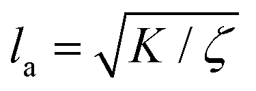 where K represents the elastic constant penalizing distortions in the orientational order, and ζ is the activity parameter. The confinement-induced order provides a means to control the flow dynamics and the solute dispersion. Beyond channel confined active nematics, dispersion has been studied in other active fluids and geometries.17–23
It has been reported that in confined active layers the velocity fluctuations render the diffusion coefficient of tracers dependent on the system size and divergent as the thickness approaches the spontaneous flow transition.24 Somewhat surprisingly, a recent analytical study of solute transport in cylindrical capillaries under activity-gradient driven flows reported lower solute dispersion when compared with the dispersion in passive fluids driven by pressure gradients.25 The flows studied in our work are self-organized, whereas the flow examined in ref. 25 is driven by an imposed activity gradient, resulting in a constant flow profile over time and along the channel axis. Consequently, the flow in ref. 25 is less turbulent compared to the flows considered in our study.
Despite these studies, the effect of confinement on solute dispersion in active nematics flows remains largely unexplored. Here we aim to start closing this gap. Specifically, we aim to investigate how solute dispersion differs in self-organized flows with net flux from those without.
We expected that the transition from directional to non-directional flow would result in a discontinuity of the effective diffusivity. Using lattice Boltzmann simulations of a confined 2D active nematic fluid, we observed markedly different dispersion behaviors in the limit of no diffusivity but found no discontinuity in the effective diffusivity for dissolved solutes. Instead, we identified a general relationship between effective diffusivity and the second moments of the velocity field, captured by an active extension of the unidirectional Taylor dispersion law.26 This extension was expected to apply to quasi-unidirectional flows. However, we found that when molecular diffusion dominates transverse transport, the solute advection becomes effectively unidirectional, even in the vortex lattices characteristic of the dancing regime. These findings provide new insights into the dispersion of nutrients and other molecules in channels containing microswimmers under different flow conditions.
II Methods
In order to simulate active nematics, we use the Landau-de Gennes free energy, written in terms of the order parameter Q. In two-dimensional uniaxial nematics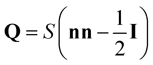 , where n is the director field, corresponding to the eigenvector with the largest eigenvalue of Q, and represents the average local orientation of the molecules. The degree of orientation is quantified by the scalar order parameter S, describing an isotropic fluid at S = 0 and a perfectly ordered nematic at S = 1. To describe the fluid motion and its couplings to nematic orientations, we use the Beris–Edwards theory of nematodynamics, starting with the advection-diffusion equation for Q:
| (∂t + uγ∂γ)Qαβ − Sαβ = ΓHαβ | (1) |
 | (2) |
 , and the shear rate tensor Dαβ is defined as
  . The molecular field H:
 | (3) |
 | (4) |
 | (5) |
 . The reason for the absence of a bulk free energy density in this model for the active nematic is that many physical systems, such as the microtubule kinesin mixtures, do not exhibit nematic order until they become active.27,28 Furthermore, theoretical and numerical results show that activity induces order in flow-aligning suspensions of extensile force dipoles.29,30 The walls of the channel will induce nematic order close to them due to the anchoring energy.
We consider an incompressible fluid governed by the Navier-Stokes equation, with the continuity equation ∂βuβ = 0 and the momentum equation:
 | (6) |
| Πaαβ = −ζQαβ | (7) |
| Πpαβ = 2ηDαβ − pδαβ | (8) |
The dispersed solute follows the diffusion equation for the concentration field c, with isotropic molecular diffusivity Dm:
| (∂t + uγ∂γ)c(r,t) = Dm∂2αc(r,t) | (9) |
We simulate this complex fluid in two dimensions, with a combination of two methods. For eqn (6) the lattice Boltzmann method, incorporating the active stress through the Guo force method.33 For eqn (1), a finite-differences method with predictor-corrector integration.3 The channel has two walls separated by a distance of L = 32. The lattice constant Δx, integration time step Δt, and the reference density ρr are set to 1, which is known as lattice units, and it will be used throughout the paper. By relating the unit length, time, and density to those values in experiments, the lattice units can be converted to physical units. We use the ratio of the active length to the channel width, to define the activity number A = L/la, for comparison with previous studies, such as ref. 34.
III Results
The system under investigation is a two-dimensional channel filled with an active nematic fluid. The channel is formed by two parallel plates separated by a distance L = 32. The channel's length Lx is significantly larger, measuring either 1024 or 2048 units, to ensure that the solute's spatial distribution remains unaffected by finite-size effects. No slip boundary conditions for the velocity field at the walls are implemented using an equilibrium scheme.33 Periodic boundary conditions are applied in the direction parallel to the walls (x-direction). We use planar anchoring only n = (1, 0) with S = 0.5 at the walls. The duration of the simulations is 2.5 × 10⁶ in lattice units, which can be compared to the reference times in Table 1.| Parameter | Value |
|---|---|
| Kinematic viscosity ν | 1/6 |
| Density ρ | 40 |
| Single elastic constant K | 0.015 |
| Alignment parameter ξ | 0.90 |
| Anchoring strength W0 | 2.0 × 10⁻³ |
| Reference molecular diffusivity Dm | 3.33 × 10⁻³ |
| Channel dimensions Lx × L | 1024 or 2048 × 32 |
| Reference oscillatory activity ζo | 8.50 × 10⁻³ |
| Reference dancing activity ζd | 1.30 × 10⁻² |
| Oscillatory active length la(ζo) | 1.30 |
| Dancing active length la(ζd) | 1.07 |
| Oscillatory active time ηζ−1o | 784 |
| Dancing active time ηζ−1d | 513 |
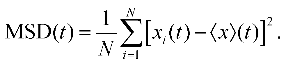
We simulate a circular drop of solute placed in the channel after the flow has reached the steady state. The solute's dispersion is quantified by the mean squared displacement (or variance) of its spatial distribution along the channel, calculated from the following expression:
 | (10) |
![[x with combining macron]](https://www.rsc.org/images/entities/i_char_0078_0304.gif) = 〈xc(x)〉x = 〈xc(x)〉x
| (11) |
|
MSD = 〈c(x)(x − )2〉x
| (12) |
A Dispersion in different flow regimes
Initially, the system is set with no flow and small random perturbations to the director field, uniformly distributed up to 2° away from the channel-aligned n = (1, 0). The error bars in the plots represent the standard deviation of 4 samples with different initial directors fields. The resulting flows are distinguished by a number of features, such as the net mass flux and the dynamics of the director field. In order of increasing activity, we observe the following regimes:Quiescent state – the velocity field is null everywhere, the director field is uniformly aligned along the channel due to the planar anchoring and the scalar order parameter is S = 0.5 everywhere. The solute dispersion is purely diffusive.
Defectless vortex lattice (DVL) – occurs in the range ζ ∈ [0.005, 0.0065] or activity number A ∈ [18, 21] where the DVL consists of counter-rotating vortices and a static spatially undulating director field. The DVL was previously described in ref. 35, where it was associated to strong anchoring. The time taken to reach this steady state increases with the proximity to the critical activity, separating the quiescent and the DVL regimes. There are no topological defects in the director field. Consequently, the fluid velocity is so small that the dispersion occurs mainly due to diffusion.
Oscillatory flow – unlike the vortex lattices that precede and follow it, this regime exhibits net flow. It occurs in the range ζ ∈ [0.0065, 0.011] or A ∈ [21, 26] and is illustrated on the left column of Fig. 1. This type of flow was observed experimentally in ref. 10 and 11 and studied numerically in ref. 10, 34 and 36–38. The flow structure, shown in Fig. 1 panel c, is characterized by an undulating region with higher velocity. Examining a constant x-coordinate cross-section, the velocity profile repeats itself in time with a characteristic period T. The ratio of the period to the “wavelength” of the undulations (phase velocity) is less than 10 times the average fluid velocity. The nematic order is characterized by two pairs of adjacent topological defects per wavelength, see Fig. 1a. There is a symmetric distribution of vorticity, resulting in no net vorticity.
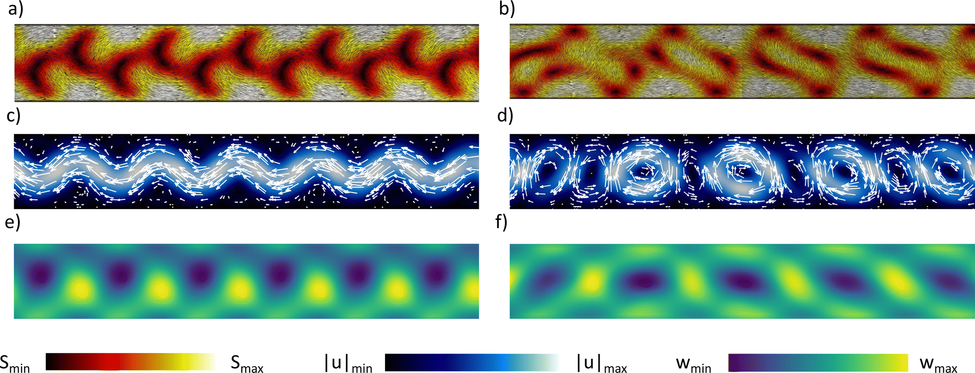 | ||
| Fig. 1 Comparison of the nematic director field, flow velocity, and vorticity in oscillatory ((a), (c) and (e)) and dancing flow ((b), (d) and (f)), in a subsection of the channel. The dimensions of the channel are given in Table 1. The nematic director field is depicted in panels (a) and (b), visualized using the line integral convolution filter of Paraview.39 The color map represents the scalar order parameter S, which varies from 0 to 0.34 in (a) and 0 to 0.42 in (b) (see Videos S1 and S2, ESI†). Velocity and vorticity are given in lattice units, which can be compared to the reference values in Table 1. The flow velocity field is shown in panels (c) and (d), with magnitude reaching 1.8 × 10⁻³ in (c) and 3.4 × 10⁻³ in (d) (see Videos S3 and S4, ESI†). The component of the vorticity out of the plane is shown in panels (e) and (f), varying in the range − 3.9 × 10⁻⁴ to − 3.9 × 10⁻⁴ in (e) and − 1.2 × 10⁻³ to 9 × 10⁻⁴ in (f) (see Video S5, ESI†). | ||
In Fig. 2 panel a, the fast-moving fluid in the center of the channel pulls the solute away from the slow-moving regions near the walls, as indicated by the orange arrows. This enhances dispersion with a linearly increasing mean squared displacement (MSD), as shown by the red line in Fig. 3.
 | ||
Fig. 2 Evolution of a solute drop in oscillatory (a) and dancing flow (b) regimes, in the section of the channel where the solute drop is initially placed. The solute concentration varies from 0 to 10−1 c0, where c0 is the initial concentration. The color scheme is saturated in the initial setup (first row) for visualization purposes. The time between the release of the solute and the pictures on the bottom row is 50![[thin space (1/6-em)]](https://www.rsc.org/images/entities/char_2009.gif) 000 simulation time steps, which can be compared to the reference times in Table 1. Videos S6 and S7 (ESI†) show this dispersion. 000 simulation time steps, which can be compared to the reference times in Table 1. Videos S6 and S7 (ESI†) show this dispersion. | ||
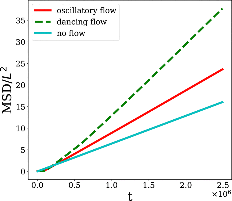 | ||
| Fig. 3 Time evolution of the mean squared displacement (MSD) of solute. The solute MSD is calculated through eqn (12). The blue line represents the passive case, with a slope 2Dm, where Dm is the molecular diffusivity. The red line corresponds to the oscillatory flow, and the green line represents the dancing flow. The simulation time steps on the horizontal axis can be compared to the reference times in Table 1. | ||
Dancing flow – the final regime considered here occurs for ζ ≥ 0.013 or A ≥ 29 and forms a vortex lattice with braiding defects. This regime has been extensively simulated and characterized in previous studies,10,14,36,40–42 so we refer the reader to these works for further details. In our simulations, this flow regime is shown on the right side of Fig. 1. Briefly, the director field, shown in Fig. 1b, features quasi-stationary negative topological defects near the channel walls, while positive defects move along the center, avoiding collisions in a manner reminiscent of Ceilidh dancing. The flow structure is characterized by pairs of counter-rotating vortices, as shown in Fig. 1d and f. We emphasize that the vortices do not maintain the same absolute vorticity; instead, their relative strengths oscillate over time, with one set of vortices (clockwise or counter-clockwise) periodically becoming stronger than the other. Additionally, due to the length of the channel, vortices nucleate at several locations simultaneously, creating asynchronous domains. These domain walls introduce random elements into an otherwise periodic steady state.
In Fig. 2b, we see that high and low concentration regions are swept by the vortices, increasing the longitudinal diffusivity. The relative increase of the diffusion coefficient is greatest for small values of Dm as seen in Fig. 5b.
B Active Taylor–Aris dispersion
For diffusive dispersion, we can define an effective diffusivity, whose minimum is the molecular diffusivity of the solute (see Table 1), by:| MSD(t) = 2Defft | (13) |
In the oscillatory regime, Deff increases linearly with the activity ζ, as shown in Fig. 4b. In the plot of Fig. 4a we find that the characteristic velocity of the flow 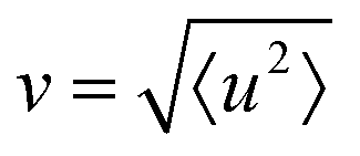 also increases linearly with the activity ζ, by contrast to the sub-linear increase ζ1/2 reported in fully developed active turbulence.43 This relationship can be anticipated by dimensional analysis where the channel width L becomes the characteristic length at small activities. In the Stokes regime, and in the absence of external pressure gradients, the viscous force balances the active force, leading to the relationship η∇2u = ζ∇·Q. Dimensional analysis then implies that U ∼ ζL/η. Additionally, the linear increase of the flow velocity v is in line with the results of the linear stability analysis reported in ref. 44. The root mean squared velocity increases more rapidly in the oscillatory than in the dancing flow regime. However, the growth rate of Deff is similar in both regimes. This suggests that the energy contributing to enhanced dispersion grows continuously. The additional energy associated with the faster velocity growth in the oscillatory regime drives the displacement of the cloud's center of mass and does not enhance the dispersion.
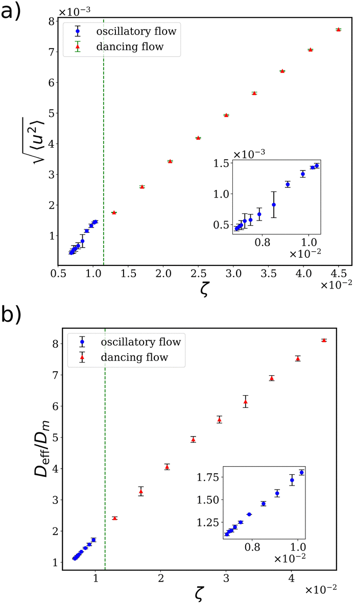 | ||
| Fig. 4 Average velocity of the flow (a) and effective diffusivity (b) as a function of activity for oscillatory flow and dancing flow. A vertical green line is halfway between ζ = 0.010 and 0.013, where the transition from oscillatory to dancing flow gradually takes place. The insets show closer views of the oscillatory regime. | ||
In Poiseuille flow (for passive Newtonian fluids), the solute is spread longitudinally with the width of the solute band increasing with  . The phenomenon is called Taylor–Aris dispersion, and it can be characterized by the effective diffusivity:
 | (14) |
 , and the coefficient 210−1 = (5 × 42)−1 is a geometrical factor for quasi-2d infinite parallel plates.45 In the 1954 paper by Aris generalizing the Taylor dispersion law, the reference frame used to derive the moments of the solute distribution is that in which the mean velocity of the stream is 〈u〉 = 0, and it is shown that the diffusion coefficient depends on the spread of the velocities and not on the absolute velocity. In the Poiseuille flow, the average velocity is proportional to the standard deviation of the velocity. In 2d the proportionality is 〈ux〉2 = 5σ2(ux), which is obtained by simple integrations of the parabolic velocity profile. For this reason, it is possible to write the classical Taylor dispersion equation using the mean velocity 〈ux〉. However, in the oscillatory flow regime, we found that 〈ux〉 and σ(ux) are not proportional, and the same is also the case for the dancing flow regime, where the average velocity is 〈ux〉 = 0. Thus, without introducing anything new, we have rewritten the classical expression using the second moment σ2(ux). Replacing 〈ux〉2 with 5σ2(ux) in eqn (14) overestimates the effective diffusivity Deff in the active flows considered here. The original Taylor–Aris approach is valid only for unidirectional flows. However, while most of the flow in the oscillatory regime is along the channel, transverse currents are also present. As a result, applying the Taylor–Aris dispersion equation overlooks the transport of solute between the fast-moving central region of the channel and the slower regions near the walls.
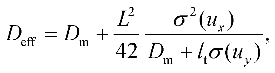
To address this, we aimed to quantify the transport in the y-direction through an effective diffusivity. We introduce an additional term to the molecular diffusivity (in the denominator), proportional to the magnitude of the transverse currents. Given the channel geometry, where 〈uy〉 = 0, we used  . This leads us to propose an active extension of the Taylor–Aris dispersion equation:
 | (15) |
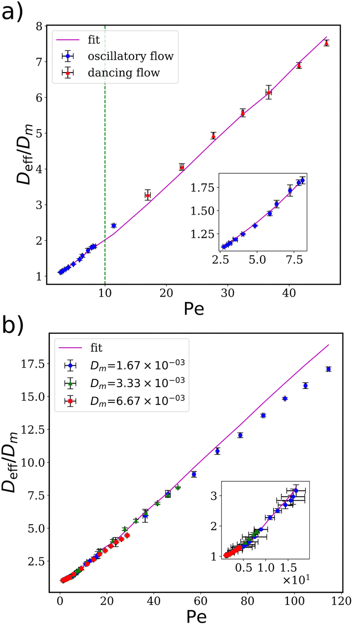 | ||
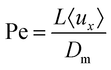
Fig. 5 Effective diffusivity in oscillatory and dancing flow, as a function of the Peclet number 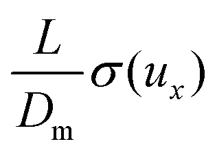 . The points represent the effective diffusivity calculated from the MSD, while the solid line shows the fit using eqn (15), with the transverse length lt = 4.2 fitted in the oscillatory regime. Panel (a) shows data for the reference molecular diffusivity. The green line, at Pe = 10, separates the two regimes. Panel (b) for solutes with double and half the reference molecular diffusivity. The fitted parameter is the same for the 3 diffusivities. Note that the fit uses the measured values of σ(uy) for each point, which changes the otherwise quadratic relationship with Pe. The error bars correspond to the standard deviation calculated from the simulations of 4 samples. . The points represent the effective diffusivity calculated from the MSD, while the solid line shows the fit using eqn (15), with the transverse length lt = 4.2 fitted in the oscillatory regime. Panel (a) shows data for the reference molecular diffusivity. The green line, at Pe = 10, separates the two regimes. Panel (b) for solutes with double and half the reference molecular diffusivity. The fitted parameter is the same for the 3 diffusivities. Note that the fit uses the measured values of σ(uy) for each point, which changes the otherwise quadratic relationship with Pe. The error bars correspond to the standard deviation calculated from the simulations of 4 samples. | ||
The form of the active Taylor–Aris dispersion in the oscillatory flow regime can be rationalized based on its similarity to Poiseuille flow, the basis of the original theory. This similarity is both geometric and hydrodynamic. First, the confining geometry is identical, leading to a much greater dispersion along the channel axis compared to the transverse direction. Second, the flow is nearly unidirectional—entirely in the case of Poiseuille flow and predominantly in the case of oscillatory flow. Surprisingly, this law extends far into the non-directional dancing regime, with the same transverse length lt = 4.2, as shown by the extrapolation depicted in Fig. 5. The invariance of the length scale is in line the spectral analysis in ref. 34, which find that both the oscillatory and dancing flows are dominated by a single length scale – the channel width L.
However, the effective diffusivity is overestimated at high Pe. We hypothesize that high molecular diffusivity causes dispersion to be dominated by diffusion, with advection contributing only minimally to solute transport from the center of the channel to the walls. As a result, the details of the transverse velocity field uy become less significant, and solute advection becomes quasi-one-dimensional. Since the Taylor–Aris dispersion law presumes unidirectional flow, we were able to describe the active dispersion using it with minimal coupling to the transverse velocity field through the term ltσ(uy), even in a non-directional flow such as the vortex lattice.
C Convection-dominated limit
Molecules undergo diffusion driven by thermal fluctuations. However, as the particle size increases, diffusion decreases, as described by the Stokes–Einstein relation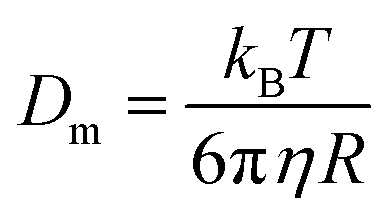 , for spherical particles of radius R, where kB is the Boltzmann constant and T is the temperature. As the particle diffusivity decreases, the Peclet number,
 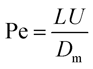 , diverges for finite U. Therefore, large colloids should exhibit much higher Pe than the solutes depicted in Fig. 5. Active fluctuations, such as those occurring in the dancing flow regime, become more relevant than thermal fluctuations as the driving mechanism for particle dispersion. Additionally, tracers can be easier to study in experiments46 and are useful to follow the trajectories of fluid particles.
In a simplified analysis, we track individual tracers with diffusivity Dm = 0. We initialize N = 1000 tracers under two distinct conditions: (1) uniformly distributed within a circle of diameter equal to half of the channel width, enabling a direct comparison with the solute dispersion, and (2) uniformly distributed throughout the entire channel, ensuring that trajectories near the walls are included. After a transient regime, tracer i follows the velocity field with 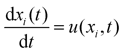 , and the cloud's center of mass along the x-direction is computed as:
 , where xi is the position of tracer i along the channel. To quantify the dispersion, we compute the mean squared displacement (MSD):
 | (16) |
The average velocity along the x-axis is given by: 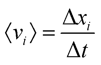 , where Δt is the total simulation time minus the transient. In the oscillatory regime and for the uniform initial condition, the distribution of 〈v〉 is tri-modal (see Fig. 6f). The three modes correspond to the trajectories shown in Fig. 6b. The distribution suggests that once a tracer is set on one of these trajectories, it remains for very long on that trajectory. The crossing of these trajectories implies that the motion depends not only on the distance from the channel walls but also on the initial phase of the traveling wave. Tracers exhibit higher average velocities as they move closer to the center of the channel.
 | ||
| Fig. 6 Dynamics of tracers and their trajectories. In (a), the log–log plot shows the MSD of tracers, calculated from eqn (16). The initial configuration is 1000 tracers distributed uniformly in a circle of diameter equal to half of the channels width. The tracers are released when the flow reaches a steady state. The comparison includes the dispersion in Poiseuille flow with the same flow rate as the oscillatory flow (ζ = 7.9 × 10⁻³). In both oscillatory and Poiseuille flows, the MSD of tracers grows ballistically, while in the dancing flow, the dispersion is diffusive. In (b) and (c), the tracers are shown shortly after they are released into the oscillatory and dancing flows respectively (see Videos S8 and S9, ESI†). In the panels that follow, the initial configuration is uniform in the whole channel. Panel (d) illustrates three typical trajectories in a subsection of the channel in the oscillatory flow regime. In order of increasing average velocity and distance from the walls, the trajectories are red, green, and purple. In (e), we illustrate typical trajectories in the dancing flow regime. The histogram in (f) depicts the distribution of the average of the absolute value of the x-component of the velocity, defined in the text. The peaks correspond to the 3 different trajectories shown in (d). A plot for the dancing flow regime is not shown as the distribution is uniform and the average velocity decreases with time due to the diffusive motion. | ||
In the oscillatory flow regime, the red curve in Fig. 6a indicates that tracers spread ballistically, as predicted by the linear stability analysis for unidirectional flow.24 While the assumption of Dm = 0 is not realistic, especially given the prevalence of fluctuations in pre-turbulent flows, it is safe to assume that the time taken for the MSD to transition from ballistic to diffusive behavior increases with Pe.
In the dancing flow regime, tracers often loop once or twice around a vortex before being ejected to a neighboring vortex. This behavior results in the irregular tracer trajectories illustrated in Fig. 6c. As demonstrated in ref. 47, oscillating vortex lattices can induce chaotic trajectories in advected tracers. This effect underpins the observed chaos, persisting even in simulations with no active fluctuations in spatial and temporal order. In contrast to the oscillatory regime, tracers in the dancing flow regime exhibit diffusive dispersion, as shown in the log–log plot of Fig. 6a. It is important to note that the difference between the dispersion of diffusive solute and ballistic tracers is also observed in Poiseuille flow, in line with eqn (14).
IV Conclusions
We investigated the dispersion of solutes in two pre-turbulent flow regimes, resulting from channel confinement of active nematic fluids: oscillatory flow, characterized by net mass flux, and dancing flow, characterized by a one-dimensional vortex lattice and lacking net flux.The results of numerical simulations revealed that at very low diffusivities, the dispersion behavior differs significantly between the two regimes. However, as the molecular diffusivity of the solute increases, the advective transport in the transverse direction becomes insignificant. This quasi-1d solute advection enables a unified description of dispersion in both flow regimes, within the framework of unidirectional Taylor–Aris dispersion. The transverse flow enhances effective transverse dispersion, which, in turn, reduces longitudinal dispersion. Thus, our proposed active Taylor–Aris dispersion law uses the variance of the transverse flow distribution in addition to the longitudinal distribution.
By contrast, tracers, which do not diffuse due to thermal fluctuations, exhibit distinct dispersion behaviors in the two flow regimes. In oscillatory flows, the tracers may be trapped by vortices near the channel walls or follow high-velocity, tortuous paths, with ballistic dispersion. In the dancing flow regime, however, tracers are flung from vortex to vortex in an irregular manner, resembling one-dimensional random walks, consistent with a diffusive dispersion.
Extensions of this work include the study of solutes dispersion in active fluids in porous media, with pores of different sizes and shapes, bringing in a different source of disorder. Additionally, the dispersion of the dissolved chemical energy source may also be considered. Previous studies of the dispersion of activity reported subdiffusive dispersion in the active turbulent regime.21,48 It remains to be seen if this result holds in pre-turbulent flow regimes and how it impacts the dispersion of solutes.
Since active turbulence is generic, the flow regimes analyzed here resulting from its confinement, should also be applicable widely, from microtubules to bacteria. The results reported here enhance our understanding of how molecules and colloids, critical to biological processes, are dispersed in confined active fluids in porous media and microfluidic devices.
Data availability
The data supporting this article have been included as part of the ESI.†Conflicts of interest
There are no conflicts to declare.Acknowledgements
We acknowledge financial support from the Portuguese Foundation for Science and Technology (FCT) under the contracts: PTDC/FISMAC/5689/2020 (DOI: 10.54499/PTDCFIS-MAC/5689/2020) UIDB/00618/2020 (DOI: 10.54499/UIDB/00618/2020), UIDP/00618/2020 (DOI: 10.54499/UIDP/00618/2020), DL57/2016/CP1479/CT0057 (DOI: 10.54499 DL57/2016/CP1479/CT0057) and 2023.10412.CPCA.A2 (DOI: 10.54499/2023.10412.CPCA.A2).References
- I. C. Engelhardt, D. Patko, Y. Liu, M. Mimault, G. De Las Heras Martinez and T. S. George, et al., Novel Form of Collective Movement by Soil Bacteria, ISME J., 2022, 16(10), 2337–2347 CrossRef CAS PubMed.
- M. J. Kim and K. S. Breuer, Microfluidic Pump Powered by Self-Organizing Bacteria, Small, 2008, 4(1), 111–118 CrossRef CAS PubMed.
- D. Marenduzzo, E. Orlandini, M. E. Cates and J. M. Yeomans, Steady-State Hydrodynamic Instabilities of Active Liquid Crystals: Hybrid Lattice Boltzmann Simulations, Phys. Rev. E: Stat., Nonlinear, Soft Matter Phys., 2007, 76(3), 031921 CrossRef CAS PubMed.
- Z. Lin, J. L. Thiffeault and S. Childress, Stirring by Squirmers, J. Fluid Mech., 2011, 669, 167–177 CrossRef.
- X. L. Wu and A. Libchaber, Particle Diffusion in a Quasi-Two-Dimensional Bacterial Bath, Phys. Rev. Lett., 2000, 84(13), 3017–3020 CrossRef CAS PubMed.
- K. C. Leptos, J. S. Guasto, J. P. Gollub, A. I. Pesci and R. E. Goldstein, Dynamics of Enhanced Tracer Diffusion in Suspensions of Swimming Eukaryotic Microorganisms, Phys. Rev. Lett., 2009, 103(19), 198103 CrossRef PubMed.
- R. Aditi Simha and S. Ramaswamy, Hydrodynamic Fluctuations and Instabilities in Ordered Suspensions of Self-Propelled Particles, Phys. Rev. Lett., 2002, 89(5), 058101 CrossRef CAS PubMed.
- U. Wolke, E. A. Jezuit and J. R. Priess, Actin-Dependent Cytoplasmic Streaming in C. Elegans Oogenesis, Development, 2007, 134(12), 2227–2236 CrossRef CAS PubMed.
- R. Alert, J. Casademunt and J. F. Joanny, Active Turbulence, Annu. Rev. Condens. Matter Phys., 2022, 13 Search PubMed.
- J. Hardoüin, R. Hughes, A. Doostmohammadi, J. Laurent, T. Lopez-Leon and J. M. Yeomans, et al., Reconfigurable Flows and Defect Landscape of Confined Active Nematics, Commun. Phys., 2019, 2(1), 121 CrossRef.
- H. Wioland, E. Lushi and R. E. Goldstein, Directed Collective Motion of Bacteria under Channel Confinement, New J. Phys., 2016, 18(7), 075002 CrossRef.
- R. J. Henshaw, O. G. Martin and J. S. Guasto, Dynamic Mode Structure of Active Turbulence, Phys. Rev. Fluids, 2023, 8(2), 023101 CrossRef.
- S. P. Thampi, Channel Confined Active Nematics, Curr. Opin. Colloid Interface Sci., 2022, 61, 101613 CrossRef CAS.
- T. N. Shendruk, A. Doostmohammadi, K. Thijssen and J. M. Yeomans, Dancing Disclinations in Confined Active Nematics, Soft Matter, 2017, 13(21), 3853–3862 RSC.
- A. J. Tan, E. Roberts, S. A. Smith, U. A. Olvera, J. Arteaga and S. Fortini, et al., Topological Chaos in Active Nematics, Nat. Phys., 2019, 15(10), 1033–1039 Search PubMed.
- F. L. Memarian, D. Hammar, M. M. H. Sabbir, M. Elias, K. A. Mitchell and L. S. Hirst, Controlling Chaos: Periodic Defect Braiding in Active Nematics Confined to a Cardioid, Phys. Rev. Lett., 2024, 132(22), 228301 CrossRef CAS PubMed.
- J. P. Hernandez-Ortiz, C. G. Stoltz and M. D. Graham, Transport and Collective Dynamics in Suspensions of Confined Swimming Particles, Phys. Rev. Lett., 2005, 95(20), 204501 CrossRef PubMed.
- P. T. Underhill, J. P. Hernandez-Ortiz and M. D. Graham, Diffusion and Spatial Correlations in Suspensions of Swimming Particles, Phys. Rev. Lett., 2008, 100(24), 248101 CrossRef PubMed.
- A. S. Mikhailov, Y. Koyano and H. Kitahata, Hydrodynamic Effects in Oscillatory Active Nematics, J. Phys. Soc. Jpn., 2017, 86(10), 101013 CrossRef.
- A. Dehkharghani, N. Waisbord, J. Dunkel and J. S. Guasto, Bacterial Scattering in Microfluidic Crystal Flows Reveals Giant Active Taylor-Aris Dispersion, Proc. Natl. Acad. Sci. U. S. A., 2019, 116(23), 11119–11124 CrossRef CAS PubMed.
- T. E. Bate, M. E. Varney, E. H. Taylor, J. H. Dickie, C. C. Chueh and M. M. Norton, et al., Self-Mixing in Microtubule-Kinesin Active Fluid from Nonuniform to Uniform Distribution of Activity, Nat. Commun., 2022, 13(1), 6573 CrossRef CAS PubMed.
- K. J. Modica, A. K. Omar and S. C. Takatori, Boundary Design Regulates the Diffusion of Active Matter in Heterogeneous Environments, Soft Matter, 2023, 19(10), 1890–1899 RSC.
- Z. Ge and G. J. Elfring, Hydrodynamic Diffusion in Apolar Active Suspensions, arXiv, 2024, preprint, arXiv:2311.09448 DOI:10.48550/arXiv.2311.09448.
- A. Basu, J. F. Joanny, F. Jülicher and J. Prost, Anomalous Behavior of the Diffusion Coefficient in Thin Active Films, New J. Phys., 2012, 14(11), 115001 CrossRef.
- S. Das, Taylor Dispersion and Concentration Profiles of Solutes in the Capillary Transport of Active Liquids, Langmuir, 2024, 40(35), 18773–18780 CrossRef CAS PubMed.
- R. Aris, On the Dispersion of a Solute in a Fluid Flowing through a Tube, Proc. R. Soc. London, Ser. A, 1956, 235(1200), 67–77 Search PubMed.
- W. Xi, T. B. Saw, D. Delacour, C. T. Lim and B. Ladoux, Material Approaches to Active Tissue Mechanics, Nat. Rev. Mater., 2018, 4(1), 23–44 CrossRef.
- M. Gupta, B. R. Sarangi, J. Deschamps, Y. Nematbakhsh, A. Callan-Jones and F. Margadant, et al., Adaptive Rheology and Ordering of Cell Cytoskeleton Govern Matrix Rigidity Sensing, Nat. Commun., 2015, 6(1), 7525 CrossRef CAS PubMed.
- S. P. Thampi, A. Doostmohammadi, R. Golestanian and J. M. Yeomans, Intrinsic Free Energy in Active Nematics, EPL, 2015, 112(2), 28004 CrossRef.
- S. Santhosh, M. R. Nejad, A. Doostmohammadi, J. M. Yeomans and S. P. Thampi, Activity Induced Nematic Order in Isotropic Liquid Crystals, J. Stat. Phys., 2020, 180(1–6), 699–709 CrossRef CAS.
- M. Golden, R. O. Grigoriev, J. Nambisan and A. Fernandez-Nieves, Physically Informed Data-Driven Modeling of Active Nematics, Sci. Adv., 2023, 9(27), eabq6120 CrossRef CAS PubMed.
- A. Doostmohammadi, J. Ignés-Mullol, J. M. Yeomans and F. Sagués, Active Nematics, Nat. Commun., 2018, 9(1), 3246 CrossRef PubMed.
- T. Krüger, H. Kusumaatmaja, A. Kuzmin, O. Shardt, G. Silva and E. M. Viggen, The Lattice Boltzmann Method: Principles and Practice. Graduate Texts in Physics, Cham: Springer International Publishing, 2017 Search PubMed.
- A. Samui, J. M. Yeomans and S. P. Thampi, Flow Transitions and Length Scales of a Channel-Confined Active Nematic, Soft Matter, 2021, 17(47), 10640–10648 RSC.
- P. Gulati, S. Shankar and M. C. Marchetti, Boundaries Control Active Channel Flows, Front. Phys., 2022, 10, 948415 CrossRef.
- S. Chandragiri, A. Doostmohammadi, J. M. Yeomans and S. P. Thampi, Active Transport in a Channel: Stabilisation by Flow or Thermodynamics, Soft Matter, 2019, 15(7), 1597–1604 RSC.
- Z. Y. Li, D. Q. Zhang and B. Li, Formation and Propagation of Solitonlike Defect Clusters in Confined Active Nematics with Chiral Anchoring, Phys. Rev. Res., 2021, 3(2), 023253 CrossRef CAS.
- C. G. Wagner, R. H. Pallock, J. S. Park, M. M. Norton and P. Grover, Exploring Regular and Turbulent Flow States in Active Nematic Channel Flow via Exact Coherent Structures and Their Invariant Manifolds, Phys. Rev. Fluids, 2023, 8(12), 124401 CrossRef.
- J. Ahrens and B. Geveci, Law C. ParaView, 2024. Available at https://www.paraview.org Search PubMed.
- A. Doostmohammadi, T. N. Shendruk, K. Thijssen and J. M. Yeomans, Onset of Meso-Scale Turbulence in Active Nematics, Nat. Commun., 2017, 8(1), 15326 CrossRef CAS PubMed.
- R. C. V. Coelho, N. A. M. Araújo and M. M. Telo Da Gama, Active Nematic-Isotropic Interfaces in Channels, Soft Matter, 2019, 15, 34 RSC.
- P. Chandrakar, M. Varghese, S. A. Aghvami, A. Baskaran, Z. Dogic and G. Duclos, Confinement Controls the Bend Instability of Three-Dimensional Active Liquid Crystals, Phys. Rev. Lett., 2020, 125(25), 257801 CrossRef CAS PubMed.
- E. J. Hemingway, P. Mishra, M. C. Marchetti and S. M. Fielding, Correlation Lengths in Hydrodynamic Models of Active Nematics, Soft Matter, 2016, 12(38), 7943–7952 RSC.
- R. Voituriez, J. F. Joanny and J. Prost, Spontaneous Flow Transition in Active Polar Gels, Europhys. Lett., 2005, 70(3), 404–410 CrossRef CAS.
- M. L. Parks and L. A. Romero, Taylor-Aris Dispersion in High Aspect Ratio Columns of Nearly Rectangular Cross Section, Math. Comput. Model., 2007, 46(5–6), 699–717 CrossRef.
- I. Vélez-Ceron, R. C. V. Coelho, P. Guillamat, M. T. da Gama, F. Sagués and J. Ignés-Mullol, Active Nematic Pumps, arXiv, 2024, preprint, arXiv:2407.09960 DOI:10.48550/arXiv.2407.09960.
- S. C. Ryrie, Mixing by Chaotic Advection in a Class of Spatially Periodic Flows, J. Fluid Mech., 1992, 236, 1–26 CrossRef CAS.
- R. C. V. Coelho, N. A. M. Araújo and M. M. Telo da Gama, Dispersion of Activity at an Active-Passive Nematic Interface, Soft Matter, 2022, 18(39), 7642–7653 RSC.
Footnote |
| † Electronic supplementary information (ESI) available. See DOI: https://doi.org/10.1039/d4sm01175a |
| This journal is © The Royal Society of Chemistry 2025 |