DOI:
10.1039/C4RA14447C
(Review Article)
RSC Adv., 2015,
5, 15205-15225
Review on carbon-based composite materials for capacitive deionization
Received
13th November 2014
, Accepted 15th January 2015
First published on 15th January 2015
Abstract
The last five decades have witnessed the rapid development of capacitive deionization (CDI) as a novel, low-cost and environment-friendly desalination technology. During the CDI process, salt ions are sequestered by the porous electrodes once exposed to an electric field. These electrodes, acting as an ion storage container, play a vital role during desalination. In this review, various carbon-based composite electrode materials, including carbon–carbon composites, carbon–metal oxide composites, carbon–polymer composites and carbon–polymer–metal oxide composites, are systematically presented. Applications of these carbon-based composite materials for the removal of the salt ions from solution are demonstrated and they exhibit improved CDI performances compared with pristine carbon electrodes.
 Yong Liu | Yong Liu received his Bachelor's degrees in Materials Chemistry from Inner Mongolia Normal University in 2011. Now, he is pursuing his PhD under the supervision of Prof. Likun Pan in East China Normal University. His research interests are the synthesis of nanomaterials and their applications in capacitive deionization and supercapacitors. |
 Chunyang Nie | Chunyang Nie received her Bachelor's and Master's degrees in Physics from the East China Normal University in 2010 and 2013. Then, she took up a PhD scholarship to work under the joint supervision of Dr Emmanuel Flahaut and Dr Marc Monthioux. Her current research project deals with the use of CNTs as templates for the synthesis of confined 1D nanocrystals. |
 Zhuo Sun | Prof. Zhuo Sun received his PhD in 1995 at Lanzhou University. His research interest includes thin film/nanostructred materials processing and applications, vacuum/plasma systems, LED, FED and solar cells. |
 Likun Pan | Prof. Likun Pan received his PhD in 2005 at Nanyang Technological University, Singapore. His research interests include the synthesis and properties of nanomaterials and their applications in capacitive deionization, photocatalysis, solar cell and Li ion batteries. He has published more than 150 journal articles with over 3000 citations. |
1 Introduction
With an increasing human population combined with the tremendous exploitation of water resources for household applications, industry and agriculture, water shortage has emerged as a major issue in the 21st century.1–3 Although there are some approaches, including economic use and recycling of water for human and animal consumption that can mitigate the problem to some extent,3 alternative sources of freshwater are required to address its growing need.
It is reported that nearly 98% of the water resources on earth are either seawater or brackish water. Therefore, desalination has become an important approach to ensure an adequate supply of freshwater.4 In recent decades, the most widely used processes in desalination plants are reverse osmosis (RO) and thermal separations, including multistage flash distillation, multi-effect distillation and mechanical vapor compression.4 Forward osmosis is a promising new process used for seawater desalination, while there is a long way to go before its practical application.5 However, when the salt concentration of water is below 5000 ppm, it becomes more advantageous to remove the relatively few salt molecules from the saline water than remove the water molecules from the saline water through water-permeable RO membranes or thermal evaporation. To produce freshwater from low-salinity water, several desalination technologies, including electrodialysis (ED),6 ion concentration polarization,1 desalination batteries,7 microbial desalination cells8 and capacitive deionization (CDI),9 have been developed. Among these technologies, CDI, also known as electrosorption or capacitive desalination,10–14 has attracted more and more attention, in recent years, because of its environmental friendliness, no secondary pollution and reduced energy consumption.9,15–18 For example, when compared with RO, CDI can operate with low (sub-osmotic) feed pressures and in theory it requires no membrane components.19
The pioneering work of CDI can be traced in the mid-1960s, which was conducted by the Caudle and Johnson groups.20,21 However, wide attention was not drawn to this area until the 1990s when Farmer et al.22,23 developed a highly-efficient CDI device based on a carbon aerogel electrode. Then, for the last two decades, CDI has entered a stage of rapid development due to the increasingly serious water scarcity.
The principle of CDI is based on imposing an external electrostatic field between the electrodes in order to force charged ions to move towards the oppositely charged electrodes, as shown in Fig. 1. The charged ions can be attracted within the electrical double layer (EDL) formed between the bulk solution and electrode interface. When the electrical field is cut off or even reversed, the absorbed ions can be released into the bulk solution and the electrodes are regenerated and ready for the next cycle. ED is regarded as the closest cousin of CDI because both of them operate with a direct electrical voltage to drive ions onto the electrodes. However, the operational voltage in the CDI process is usually below 1.2 V, which is considerably lower than that used in the ED process. In addition, no membranes are involved in the CDI process. According to the work of Anderson4 in which these two technologies were analyzed comparatively from the aspect of energy consumption, ED cannot compete with CDI even in high concentration saline water.
 |
| | Fig. 1 Schematic diagram of CDI. | |
As reported by Humplik et al.,3 there are some major challenges for the development of economical CDI systems, including high energy consumption related to parasitic reactions at the electrodes, inadequate electrical connectivity to the high surface area electrodes and the limitations of the electrode materials and geometries that lead to trade-offs between maximizing the surface area and minimizing the distance for ionic electromigration. To achieve better insight into identifying the optimal electrode geometries and operating conditions in future CDI systems, many studies have been devoted to explore an appropriate EDL model within the CDI electrode, as the classical electrokinetic theory cannot be applied. Additionally, studies have started to address the ion transport process model by coupling a macroscopic description of the CDI process with a modified EDL model within the electrode.24–26 Despite these theoretical developments, significant research efforts have mainly been focused on the utilization of various types of materials for CDI electrodes.
Generally, CDI electrodes are made of porous carbon materials with high specific surface area and superior conductivity, both of which will be of great advantage in absorbing large quantities of salt ions for desalination.27 To date, high surface area carbon electrodes in a variety of forms: carbon aerogels (CAs),10,23,28 activated carbon (AC),29–33 including activated carbon cloth (ACC)34,35 and activated carbon fibers (ACFs),36–38 carbon nanotubes (CNTs),16,39,40 mesoporous carbon (MC),41–44 carbon nanofibers (CNFs)45 and graphene,46–48 have been reported as CDI electrode materials. However, some carbon materials suffer from problems, such as high manufacturing costs, poor wettability or poor mechanical stability.
Carbon based composite materials that take advantage of the physical and chemical properties of carbon and another one or even two different constituent materials became popular for CDI electrodes recently because of the relatively low adsorption capacity of single component carbon material, which limits CDI from being used for scaling-up applications.49,50 These additional components in the composite, typically carbon, metal oxide or polymer, can enhance the electrosorption capacity of pristine carbon materials by adjusting the intrinsic pore structure or improving the surface chemistry with functional groups, wettability and zeta potential.
In this review, we have summarized the carbon-based composite electrode materials for CDI reported in the literature to date and categorized them into four types: carbon–carbon composite, carbon–metal oxide composite, carbon–polymer composite and carbon–polymer–metal oxide composite materials. These composite materials will be discussed in detail in this manuscript.
2 Carbon–carbon composite
2.1 CNTs based composite
An enormous amount of research has been triggered since the first discovery of CNTs in 1991.51 The unique structure of CNTs comprising of a class of engineered nanoparticles (NPs) composed of extensive sp2 carbon atoms arranged in fused benzene rings gives them remarkable mechanical, electrical, optical and thermal properties, which are in turn utilized in various applications, such as aerospace,52 medical,53 energy storage devices54,55 and water treatment technologies.56–58
Fig. 2(a) and (b) show typical scanning electronic microscopy (SEM) and transmission electronic microscopy (TEM) images of CNTs. The curled structure of individual nanotubes can be observed. The nanotubes are highly entangled with each other as a result of van der Waals forces of attraction and form an interconnecting network microstructure, which provides many tunnels for the solution to enter and allows hydrated ions to easily move onto the surface of the CNTs.39
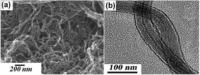 |
| | Fig. 2 SEM and TEM images of CNTs. (Reproduced with permission from ref. 59.) | |
In the last ten years, CNTs have been successfully introduced into CDI systems as the electrode material and received special attention for their exceptional capacity in capacitive desalination.16,39,40,60–64 In order to further enhance the desalination performance, combining CNTs with other types of carbon electrode materials to obtain composites that inherit the merits of both materials is regarded as an efficient alternative.
2.1.1 CNTs–AC composite. Shi et al.65 fabricated CNTs–AC composite electrodes and conducted a series of electrosorption experiments using a flow-through capacitor apparatus (Fig. 3(a)) based on such composite electrodes. The commercial CNTs and AC were mixed in different ratios and pressed using phenolic resin as the binder. After carbonization at 850 °C in an N2 atmosphere, they were used as CDI electrodes with a size of 115 mm × 75 mm. A 5000 mg L−1 NaCl solution was passed through the apparatus at a flow rate of 20 mL min−1, in which the number of electrodes was 40. A voltage of 1.0 V was imposed. The experimental results show that the composite electrode containing 10 wt% CNTs exhibited the best performance with greater than 90% removal efficiency (Fig. 3(b)) and that the energy-consumption was reduced by about 67% when compared with that of the AC electrode. As observed from Fig. 3(c), a suitable amount of CNTs could bridge the macropores, increase the number of mesopores and the specific surface area of the composite. However, excessive CNTs (>10 wt%) were not beneficial for the electrosorption due to the low specific surface area compared with that of AC. Furthermore, highly efficient regeneration of the composite electrodes was easily achieved, as shown in Fig. 3(d).
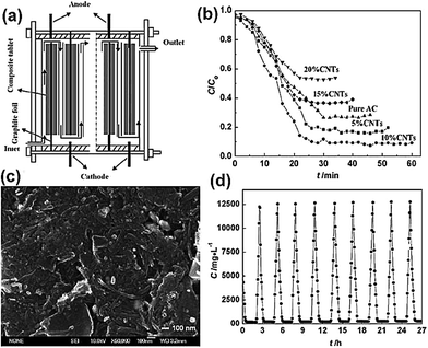 |
| | Fig. 3 (a) A schematic diagram of the flow-through capacitor apparatus; (b) comparison of the removal characteristics of the CNTs–AC composite electrodes; (c) SEM image of the composite electrode with 10 wt% CNTs; (d) removal and regeneration curve for the composite electrode with 10 wt% CNTs. (Reproduced with permission from ref. 65.) | |
2.1.2 CNTs–MC composite. Since Zou et al.42 introduced MC in the CDI field, it has attracted considerable attention because of its regular mesoporous arrangement, narrow pore size distribution, high-specific surface area, chemical inertness and high conductivity.42 Recently, Zhang et al.66 synthesized CNTs–MC composite electrodes through an inorganic–organic classic self-assembly route with soft templates for CDI. In their experiments, various quantities of CNTs were added in an ethanol solution containing NaOH, phenol and formaldehyde with triblock copolymer F127 as a template. The as-made CNTs–copolymer mixture was calcined at 600 °C for 4 h, and then cooled down to room temperature under a protective N2 atmosphere. The TEM and SEM observations in Fig. 4(a) and (b) show the 2D hexagonally ordered mesoporous channels and nanotubular morphology of the CNTs–MC composites. The CNTs additive was inserted in the mesoporous structure to form a conductive network, which could reduce the resistance of the electrode although at the cost of its specific surface area. The CDI experiments were conducted in a continuously recycling system using 40 ppm NaCl solution as the feed solution. The total solution volume was 35 mL and the mass of each electrode was 1.2 g. Fig. 4(c) describes the electrosorption behavior of AC, MC and the CNTs–MC composite with 10 wt% CNT. The electrosorption capacity of the CNTs–MC was calculated to be 0.63 mg g−1, which was considerably higher than those of MC (0.54 mg g−1) and AC (0.22 mg g−1). The results proved that the electrosorption capacity of MC could be enhanced with the CNTs additive due to the formation of the conductive network among the mesoporous structures.
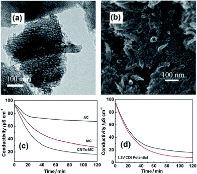 |
| | Fig. 4 (a) TEM and (b) SEM images of the CNTs–MC composite (10 wt% CNTs); (c) comparison of the CDI profiles for the CNTs–MC composite (10 wt% CNTs), MC and AC electrodes in a NaCl aqueous solution. (Reproduced with permission from ref. 68.) (d) CDI performance of the CNTs–MC electrodes before KOH activation (black line) and after KOH activation (red lines) in a NaCl aqueous solution. (Reproduced with permission from ref. 67.) | |
Further experiments were carried out by same group67 treating the CNTs–MC composites with KOH activation. It was found that after activation, new micropores were generated to increase the surface area and extend the pore size and volume, which was attributed to the interconnected micro/mesopores being etched by KOH on the pristine mesoporous channels. As shown in Fig. 4(d), the KOH activation improves the electrosorption capacity of the CNTs–MC from 0.63 mg g−1 to 0.69 mg g−1 due to the well-connected micro/mesoporous structure formed upon KOH activation, which facilitates ion transportation and diffusion.
2.1.3 CNTs–CNFs composite. Another type of CNTs composite electrode was developed by Pan et al.69–72 using a low temperature and low pressure chemical vapor deposition (CVD) method in which acetylene was used as the carbon feedstock and hydrogen as the carrier/dilution gas. The CNTs–CNFs composite was directly grown onto a conductive layer as the CDI electrode at a temperature of 550 °C. This method can greatly reduce the contact resistance and avoid the use of a binder, which can result in the loss of specific surface area and simplify the electrode preparation process. Fig. 5(a) and (b) show the SEM and TEM images of the CNTs–CNFs films. The diameters of the CNTs and CNFs are about 15–50 nm and 80–130 nm, respectively. The CNTs and CNFs are entangled and form a continuous electroconducting network structure. Fig. 5(c) demonstrates that most of the pores are smaller than 100 nm in diameter and show two peak distributions of pore size at 4 and 30 nm, namely, the CNTs–CNFs composite films are mainly composed of mesopores (2–50 nm). Such a mesoporous network structure ensures a low mass transfer and allows hydrated ions to easily enter into the deep pores, which is beneficial for ion adsorption. The CDI experiments were conducted in a continuously recycling system at a flow rate of 14 mL min−1 using NaCl solution (40 mL) with an initial conductivity of 100 μS cm−1. The CNTs–CNFs composite film electrodes exhibit a high electrosorption capacity (3.32 mg g−1), which is much better than those of conventional AC and MC electrodes, and comparable to that of a CAs electrode (3.33 mg g−1) when the applied voltage was 1.2 V, although their specific surface area was considerably smaller than these electrodes.27,70 Furthermore, no decline in the desalination efficiency was observed in the as-fabricated unit cell after over 30 charge–discharge experiments, demonstrating that the regeneration was very efficient.
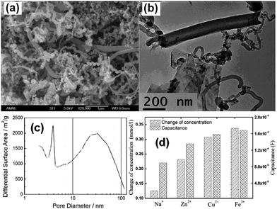 |
| | Fig. 5 (a) SEM and (b) TEM images of the CNTs–CNFs composite. (Reproduced with permission from ref. 75.) (c) Pore size distribution of the CNTs–CNFs composite. (Reproduced with permission from ref. 70.) (d) Electrosorption capacity and double layer capacitance of the CNTs–CNFs composite electrodes in different cation solutions. (Reproduced with permission from ref. 71.) | |
After that, several significant aspects, such as the adsorption isotherm, adsorption selectivity and adsorption kinetics were investigated. It was found that the Langmuir isotherm could describe the ion adsorption behavior inside the CDI, indicating a monolayer coverage of ions on the electrode surface. The kinetic and thermodynamic analyses indicated that the NaCl adsorbed onto the CNTs–CNFs electrodes follow a pseudo-first-order kinetics model and was driven by a physisorption process.69,73,74 Further experiments on the ion removal selectivity illustrated that the ion removal capacity of such mesoporous CNTs–CNFs electrodes was strongly dependent on the charge and radii of the ions. Taking cations, for example (Fig. 5(d)), multivalent cations were preferentially adsorbed from the aqueous solution while for cations with the same charge, the cations with a smaller hydrated radius would be removed more effectively.71
2.2 Graphene based composite
Graphene, an atom-thick two-dimensional (2D) carbon nanostructure with novel physical and chemical properties, has attracted extensive attention in many fields since 2004.76–79 Chemical approaches via the reduction of graphite oxide (GO), for the large-scale production of reduced graphene (RG) sheets, have become a reality.80 Theoretically, the surface area of a single graphene layer can reach as high as 2630 m2 g−1 and the corresponding conductivity is 7200 S m−1, substantially higher than that of AC. These intriguing properties endow graphene to be used as electrode material for energy storage devices and CDI.48,81 Pan et al.46 first introduced RG into CDI in 2009. The RG was synthesized using the modified Hummers method and hydrazine reduction. As shown in Fig. 6(a) and (b), the SEM and TEM images of RG show that the corrugated and scrolled sheets resemble a flower-shape and porous structure, which facilitates the high storage capacity of ions from solution. The electrosorption capacity of RG was calculated to be ∼1.4–1.9 mg g−1 when the initial concentration of NaCl was 25 mg L−1, which is higher than that of AC under the same experimental conditions.46,47 However, an issue associated with the preparation of RG via the oxidation and reduction of graphite is that incomplete chemical reduction or large aggregates are often observed.82 Hence, the resulting graphitic regions are limited, which is detrimental to carrier transport and conductivity due to the disruption of the conjugated graphitic structure by epoxide and hydroxyl groups on either side of the RG basal plane.83
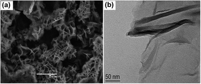 |
| | Fig. 6 (a) SEM and (b) TEM images of RG. (Reproduced with permission from ref. 46.) | |
Currently, a particularly attractive option is to design and develop composites based on RG sheets to solve the above problems.84–89 Some attempts have applied RG based composites in the CDI field, which are described in detail as follows:
2.2.1 RG–AC composite. Pan et al.90 synthesized RG–AC composites and studied their performance as CDI electrodes. GO was prepared according to the modified Hummers method by oxidizing graphite powder using a strong oxidizing agent (concentrated nitric acid and concentrated sulfuric acid)46 and AC was oxidized in nitric acid. GO was mixed with oxidized AC, and then reduced using hydrazine. A “plane-to-point” (RG to AC) conducting network structure in the RG–AC composite, as illustrated in the Fig. 7(a), was proposed. It can be clearly seen that AC is wrapped in large exfoliated RG layers and the RG sheets bridge the gaps between the AC particles. Such a “plane-to-point” porous network structure not only improves the electrical conductivity of the composite but also increases the proportion of mesopores, which contributes to the enhanced electrosorption capacity of the RG–AC electrode when compared with the AC electrode, as shown in Fig. 7(a). The electrosorption capacity was calculated by CDI experiments in a continuously recycling system at a flow rate of 25 mL min−1. NaCl solution with an initial conductivity of 50 μS cm−1 was employed as the feed solution and a direct voltage of 1.0 to 2.0 V was applied. However, the rate constant of electrosorption kinetics for the composite electrode was lower than that found for the AC electrode, as shown in Fig. 8(b). The possible mechanism of ion transfer in the AC and RG–AC electrodes is presented in Fig. 7(b). In RG–AC electrode, the “plane-to-point” conducting network is beneficial for decreasing the aggregation of AC particles, and therefore enhances the pore availability. In this case, the ions can be transported inside the RG–AC electrode, resulting in a low rate constant. As for the AC electrode, due to the presence of strong aggregation among the AC particles and a large number of micropores, the ions cannot easily enter into the inside pores, resulting in a high rate constant.
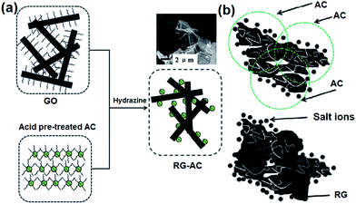 |
| | Fig. 7 Schematic diagrams for (a) the synthesis of the RG–AC composite and (b) the proposed electrosorption mechanism of ions onto AC and the RG–AC electrodes. (Reproduced with permission from ref. 90.) | |
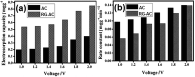 |
| | Fig. 8 (a) Electrosorption capacity of the AC and RG–AC (20 wt% RG) electrodes at different voltages in NaCl solution with an initial conductivity of 50 μS cm−1; (b) rate constants of the electrosorption kinetics for AC and RG–AC (20 wt% RG) electrodes at different voltages. (Reproduced with permission from ref. 90.) | |
2.2.2 RG–MC composite. Zhang et al.91 fabricated a RG–MC composite using an inorganic–organic classic self-assembly route with soft templates for CDI. RG nanosheets were produced by the thermal exfoliation of GO and the preparation procedure of RG–MC is similar to that of the CNTs–MC composite described in Section 2.1.2. The RG–MC composite exhibits mesoporous and paper-like structures, as shown in Fig. 9(a). The well-dispersed RG nanosheets work as a conductive carrier to support the well-arranged mesoporous channels on the surface. The surface area and conductivity are enhanced, ensuring a low energy cost during the CDI process. The CDI experiments were carried out in a continuously recycling system in NaCl aqueous solution with an initial conductivity of 89.5 μS cm−1 at an applied voltage of 2.0 V. The total volume and flow rate of the solution were 40 mL and 25 mL min−1, respectively. The mass and size of the electrode was 1.0 g and 70 mm × 80 mm, respectively. The electrosorption capacity of the RG–MC (5 wt% RG) and MC electrodes were 0.73 and 0.59 mg g−1, respectively, and both of them are considerably higher than that of the AC electrode, as shown in Fig. 9(b). The enhanced desalination performance of the RG–MC composite can be attributed to the improved electric conductivity, high and controllable specific surface area, as well as a uniform pore size distribution.
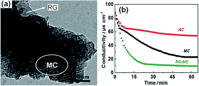 |
| | Fig. 9 TEM image of (a) the RG–MC composite with 5 wt% RG; (b) a comparison of the CDI curves for the AC, MC and RG–MC (5 wt% RG) electrodes in a NaCl aqueous solution. (Reproduced with permission from ref. 91.) | |
2.2.3 RG–CNTs composite. Zhang et al.84 first reported the fabrication of RG–CNTs composites with different proportions of CNTs for CDI. In their work, GO was synthesized using the Hummers method.92 Then, various masses of CNTs were added to the GO solution in an ice bath. The RG–CNTs were produced using thermal exfoliation of the GO–CNTs at 300 °C for 10 min under an air atmosphere. From the TEM image shown in Fig. 10(a), it can be seen that the tortuous CNTs are uniformly dispersed onto the thin wrinkled RG surface to form a porous, crumpled and loose architecture. The addition of CNTs into the composites not only increases the specific surface area by reducing the agglomeration of RG and improves the conductivity but also results in narrow pore sizes and an increased proportion of mesopores. The CDI experiments were carried out in a continuously recycling system using the RG–CNTs electrodes (10 wt% CNTs) in NaCl aqueous solution with an initial conductivity of ∼57 μS cm−1 at an applied voltage of 2.0 V. The total volume and flow rate of the solution were 35 mL and 25 mL min−1, respectively. As shown in Fig. 10(b), the composite shows a higher electrosorption capacity (1.41 mg g−1) when compared with pure RG (1.10 mg g−1) and AC (0.99 mg g−1) due to its high surface area and good conductive network formed between the CNTs and RG.
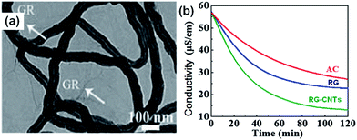 |
| | Fig. 10 (a) TEM image of the RG–CNTs composite with 10 wt% CNTs; (b) comparison of the CDI profiles for the RG–CNTs (10 wt% CNTs), RG and AC electrodes in an NaCl aqueous solution. (Reproduced with permission from ref. 84.) | |
Recently, another two papers on the use of RG–CNTs composites as CDI electrodes were published by Li et al.93 and Zou et al.94 In these two papers, the composites were synthesized by reducing a mixture of GO solution and acid oxidized CNTs solution using hydrazine with different mixing ratios of RG to CNTs. When compared with pure RG or CNTs, the RG–CNTs exhibited a higher electrosorption capacity and faster desalination. The significant improvement in desalination performance was mainly ascribed to the existence of CNTs, which acted as wires connecting the large RG sheets together and filling the vacancies, as well as reducing the aggregation of RG. The conducting network structure formed could serve as fast electronic and ionic conducting channels.87,95
A type of RG–CNTs hybrid aerogel was also studied by Zhang et al.96 as a CDI electrode. The synthetic procedure is described as follows: pre-dispersed GO sheets and multi-walled CNTs were mixed homogenously. Then, vitamin C was added as a reducing agent for the reduction of GO to RG.97 The RG–CNTs hydrogel precursors were obtained by heating the mixtures, and then drying them in supercritical CO2 to obtain the aerogel. The porous structure of the RG–CNTs hybrid aerogels was revealed by the SEM images shown in Fig. 11. A three-dimensional network structure composed of hierarchical pores can be observed. Randomly oriented CNTs and wrinkled RG sheets were well dispersed in the monolithic aerogel matrix with a number of mesopores. Such a hierarchically porous structure is favorable for mass transfer and can reduce the transport limitations.98 The resulting RG–CNTs hybrid aerogel shows an extremely high electrosorption capacity (633.3 mg g−1) in NaCl solution with an initial concentration up to 35 g L−1 measured in a continuously recycling system at an applied voltage of 1.0 V, which is considerably better than the reported maximum capacity among various electrode materials for CDI reported to date. The superior desalination performance was attributed to several factors, including the hierarchically porous structure of the hybrid aerogel,98 the functional groups attached to the surface of the RG sheets and/or CNTs,99 the high conductivity resulting from the interconnection among RG and CNTs, as well as the large surface areas of these hybrid aerogels.
 |
| | Fig. 11 (a) Low-magnification and (b) high-magnification SEM images of the RG–CNTs hybrid aerogels. The arrows in (b) are an indication of the CNTs. (Reproduced with permission from ref. 96.) | |
2.3 Other carbon–carbon composite
2.3.1 CAs–AC composite. Kohli et al.100 synthesized mesoporous CAs–microporous AC composite electrodes for CDI applications. The CAs were prepared by supercritically drying and carbonizing the gel of resorcinol and furfural in isopropanol, and AC was commercial product. The CDI experiment was carried out in 1000 mg L−1 NaCl solution at a voltage of 1.2 V. The solution volume and the electrode size were 100 mL and 10 cm × 10 cm, respectively. A highest salt removal capacity of 17 mg g−1 was observed for the composite electrode with CAs and AC in the ratio of 75![[thin space (1/6-em)]](https://www.rsc.org/images/entities/char_2009.gif) :
:![[thin space (1/6-em)]](https://www.rsc.org/images/entities/char_2009.gif) 25, which was higher than those found for pure CAs (13 mg g−1) and AC (7 mg g−1). The excellent CDI performance of the composite electrode was ascribed to the combination of the mesopores in CAs and the high surface area of AC. A regeneration efficiency of ∼92% for the composite electrode was obtained for a number of adsorption and desorption cycles.
25, which was higher than those found for pure CAs (13 mg g−1) and AC (7 mg g−1). The excellent CDI performance of the composite electrode was ascribed to the combination of the mesopores in CAs and the high surface area of AC. A regeneration efficiency of ∼92% for the composite electrode was obtained for a number of adsorption and desorption cycles.
2.3.2 ACFs–carbon black (CB) composite. Qiu et al.101 proposed a new strategy of fabricating hierarchical electrospun ACFs webs with tuned micro-, meso- and macro-porous structure by incorporating 5 wt% CB in a polyacrylonitrile precursor solution. In their experiments, the as-made ACFs–CB composite webs activated at 900 °C in flowing CO2 (ACF/CB900) were robust and flexible. From the SEM images shown in Fig. 12(a) and (b), it can be observed that the agglomerated CB has effect on the smooth cylindrical shape of the fibers in the composite webs. The TEM image (Fig. 12(c)) further confirms that the CB particles were embedded in the carbon fibers (CFs) matrix and some pores were formed in both the fibers and in the junctions between the fibers and CB. The incorporation of CB in the composite increases the electrical conductivity by 3 times and the mesopore proportion by 32% in comparison to pristine ACF900 webs without any CB. During electrosorption, the NaCl solution was continuously pumped into the cell at a rate of 5 mL min−1. The applied potential and initial NaCl concentration was 1.6 V and 90 mg L−1, respectively. The electrosorption capacity of the ACFs and ACFs–CB web electrodes activated at different temperatures were compared, as shown in Fig. 12(d). The mass of the web electrode was about 0.2 g. It was found that the electrosorption capacity of the ACFs–CB electrodes increased by 84–116% in comparison to the ACFs electrode without CB, depending on the activation temperature. The composite electrodes also exhibited good regeneration ability over charge–discharge cycles.
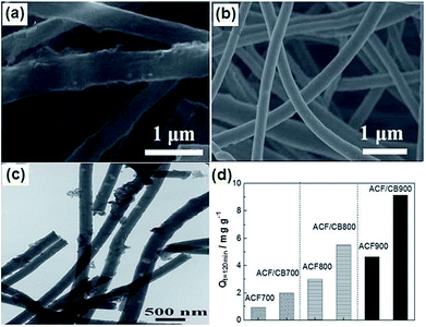 |
| | Fig. 12 SEM images of (a) ACF/CB900 and (b) ACF900; (c) TEM image of ACF/CB900; (d) electrosorption capacity of the ACFs and ACFs–CB web electrodes activated at different temperatures. (Reproduced with permission from ref. 101.) | |
2.3.3 ACFs–CNFs composite. Pan et al.102 fabricated ACFs–CNFs composite electrodes by depositing CNFs onto commercial ACFs films via a CVD method using acetylene and hydrogen mixture gas for different times. From the SEM and TEM images shown in Fig. 13(a)–(c), it can be observed that good contact between the ACFs and CNFs was formed and the average diameters of CNFs were about 20–40 nm. The electrosorption experiments were conducted in a continuously recycling system using NaCl solution with an initial conductivity of 50 μS cm−1 at a flow rate of 40 mL min−1. A direct voltage of 1.2 V was applied and the electrode size was 80 mm × 80 mm. Fig. 13(d) displays the desalination performance of the ACFs and different ACFs–CNFs composite electrodes. The results show that due to its optimized mesoporous structure and wettability, the ACFs–CNFs composite electrode with CNFs deposited in 1 h (ACFs/CNFs-1 h) exhibits the best desalination performance with a maximum electrosorption capacity of 17.19 mg g−1, which is considerably higher than that for the ACFs (1.85 mg g−1). The good regeneration of the composite electrodes was also realized over charge–discharge cycle testing.
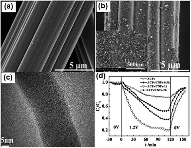 |
| | Fig. 13 SEM images of (a) ACFs and (b) ACFs/CNFs-1 h; (c) TEM image of ACFs/CNFs-1 h; (d) electrosorption process for the different electrodes in NaCl solution. Initial 30 min: physical absorption; subsequent 120 min: electrosorption; final 30 min: desorption. The inset in (b) is the corresponding magnified image. (Reproduced with permission from ref. 102.) | |
3 Carbon–metal oxide composite
Carbon and metal oxides are two hotspots as electrode materials for supercapacitor applications.103,104 The combination of these two types of materials improves the specific capacitance largely due to their synergistic effects.105,106 Because of the similar principle between supercapacitor and CDI, such carbon–metal oxide composites have also been explored in CDI applications.107,108 The metal oxide on carbon electrodes may contribute to the CDI desalination efficiency with their suitable physicochemical properties such as high hydrophilicity to increase the wettability of the electrode, inhibition of physical adsorption of ion species affecting the electrochemical adsorption/desorption during CDI operation,107,108 or alteration of the surface zeta-potential on the carbon electrode to increase the ion removal rate.109 However, an important issue noticed was that some metal oxides, typically ZnO, are not stable in acidic or basic solutions. The dissolution of such metal oxides will release additional ions, which can interfere with the experimental data by affecting the solutions conductivity.
3.1 AC–TiO2 composite
Seo et al.108,110 first reported the utilization of ACC by TiO2 modification for CDI. The modified electrode was prepared using the reaction between ACC and alkoxide by immersing pure ACC in anhydrous ethanol solution containing titanium butoxide. TiO2-modified ACC with different loadings were obtained by changing the concentration of titanium butoxide. No noticeable difference in the SEM images of ACC and Ti (0.81)/ACC (6.4 wt% TiO2) was observed, as shown in Fig. 14(a) and (b), which indicated the high dispersion of TiO2 on the surface of ACC. During the CDI experiments, the initial concentration of NaCl solution and applied voltage were 0.1 mM and 1.0 V, respectively. The effective electrode area was 4.5 cm × 4.5 cm. The CDI performance of ACC and the modified ACC are depicted in Fig. 14(c). When compared with pure ACC, the Ti (1.05)/ACC (8.4 wt% TiO2) shows a reduced physical adsorption capacity but increased electrosorption capacity. The considerable decrease in physical adsorption was attributed to the lower surface area of Ti (1.05)/ACC (1890 m2 g−1) than that of ACC (1980 m2 g−1), as well as the introduction of metal atoms through the reaction between metal alkoxide molecules and the polar groups of ACC because the polar groups worked as adsorption sites for physical adsorption. On the other hand, the incorporation of metal atoms on the surface of ACC enhanced its positive potential, and therefore improved the electrosorption capacity. In addition, TiO2 was a well-known material to be partially reduced in reduction environments110 and the conversion of the electric properties of titanium atoms due to the charged electric field was also responsible for the significant rise in electrosorption capacity. The absorbed amount of NaCl gradually increased with the loading amount of TiO2 and Ti (1.05)/ACC ranks the best, as shown in Fig. 14(d). The Ti (1.05)/ACC electrode also exhibited good regeneration ability by charge–discharge cycle testing.
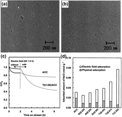 |
| | Fig. 14 SEM images of (a) ACC and (b) Ti (0.81)/ACC; (c) adsorption profiles of NaCl on the ACC and Ti (1.05)/ACC electrodes; (d) physical adsorption and electric field adsorption of the modified ACC electrodes. (Reproduced with permission from ref. 110.) | |
Recently, Chang et al.107 reported an AC electrode modified with TiO2 for CDI. The AC loaded with TiO2 (AC-TiO2) electrode was fabricated as follows: first, a mixture of HNO3, anhydrous ethanol, polyethylene glycol and distilled water in a certain ratio was slowly added to an anhydrous ethanol solution containing titanium butoxide. Then, the obtained TiO2 solution was mixed with pretreated AC powder and evaporated at room temperature. The carbonization of the electrode was achieved at 850 °C for 2 h in an N2 atmosphere to improve the pore structure and hydrophilicity. From the SEM images shown in Fig. 15(a) and (b), it can be observed that a lot of flocculent substance appears on the surface of the AC-TiO2 electrode, which could be the accumulation of TiO2 during the high-temperature annealing process. A series of desalination experiments were carried out using 20 mL of NaCl solution with an initial concentration of 500 mg L−1 at an operating voltage of 1.2 V. As observed in Fig. 15(c), the AC-TiO2 electrode exhibits a reduced physical adsorption capacity and increased electrosorption capacity when compared with the AC electrode, which is similar to the result reported by Seo et al.110 The reversibility of the AC-TiO2 electrode was also investigated and the results are displayed in Fig. 15(d), which reveal that by applying a reverse voltage of −1.2 V for 10 min and 0 V for 20 min the regeneration could be easily accomplished.
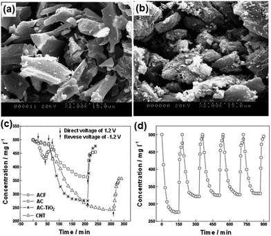 |
| | Fig. 15 SEM images of (a) AC and (b) AC-TiO2; (c) desalination and desorption curves for the different electrodes; (d) electrosorption and desorption cycles for the AC-TiO2 electrode. (Reproduced with permission from ref. 107.) | |
More recently, a microwave-assisted ionothermal approach was used to synthesize an AC-TiO2 composite as a CDI electrode material.111 When compared with a conventional sol–gel method that involves high temperature and long post-calcination time, the microwave assisted ionothermal method has emerged as a new and fast route for the production of inorganic crystalline materials and their composites under ambient conditions.112,113 In this work, a controlled sol–gel reaction step and a crystallization step induced by [Bmin]+[BF4]− ionic liquid (IL) were involved. In the first step, a determined amount of AC was dispersed in isopropyl alcohol (IPA), and then mixed with titanium tetraisopropoxide, IL and deionized water. After that, the mixture was stirred under microwave irradiation for 30 min. To crystallize the composite, IL and deionized water were added to the IPA solution containing the product from the first step and the obtained mixture was stirred under microwave irradiation for 60 min. The CDI experiments were carried out in a continuously recycling system at a flow rate of 12 mL min−1. 150 mL of a 100 mg L−1 NaCl solution and a working voltage of 1.2 V were used. The AC-TiO2 composite electrode achieved a maximum electrosorption capacity of 8.05 ± 0.34 mg g−1, which is considerably higher than that of the pure AC electrode (5.43 ± 0.91 mg g−1). This result was in accordance to the other reports.107,110
In another recent work,114 a highly durable TiO2 coated carbon electrode was fabricated using the sol–gel spraying of a titanium butoxide precursor onto an AC electrode. In the CDI experiment, the 10 mM NaCl solution was supplied to the CDI unit cell by a peristaltic pump at a flow rate of 10 mL min−1 and a 1.2 V voltage was applied. The TiO2 coated electrode showed approximately two times higher electrosorption capacity (17 mg g−1) than the carbon electrode itself (9 mg g−1), although the specific capacitance of the TiO2 coated electrode was not significantly different from that of the carbon electrode. This enhanced desalination performance was attributed to the facile accessibility of water and ions from bulk solution to the electrode surface because of the high wettability of the TiO2 coated electrode.
3.2 AC–ZnO composite
Myint and Dutta115 reported a ZnO nanorods (NRs) modified ACC electrode via a nanoparticle seeding process and hydrothermal process for CDI applications. Different ACC–ZnO composite samples were synthesized using pretreatment and changing the concentration and pH value of the precursor solutions, as well as their growth time, and their morphologies examined by SEM (Fig. 16). It was found that the experimental conditions, such as pretreatment, pH of the precursor solutions and growth time, affect the surface morphology of the composites. A series of desalination experiments using the ACC–ZnO electrodes (area 8.41 cm2) were conducted with a feed solution of 100 ppm NaCl solution and a flow rate of 2 mL min−1 under an imposed potential of 1.2 V. Fig. 17 shows the desalination and regeneration performance of the electrodes. It was found that the desalination efficiency of the composite electrodes was improved when compared with pure ACC electrode. For the electrodes obtained with pretreatment, a maximum desalination efficiency of 34% was achieved when the ZnO growth time was 10 h and for the electrodes fabricated under controlled pH conditions the desalination efficiency improves upon increasing the growth time, while the regeneration efficiency was considerably reduced. In their subsequent work,116 Dutta et al. further studied the electrodes consisting of ZnO micro/nanostructures (NPs, NRs, microsheets and microspheres) hydrothermally grown on ACC for CDI applications. The morphology of the ZnO structures was found to significantly affect the salt removal efficiency of the composite electrodes. A highest salt removal capacity of 8.5 mg g−1 was achieved for both the ZnO microsheets grafted ACC electrode and ZnO NRs grafted ACC electrode, which was considerably higher than those for pure ACC (5.8 mg g−1) and other ZnO structure coated ACC electrodes, as shown in Fig. 18.
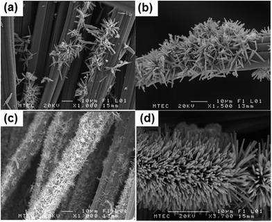 |
| | Fig. 16 SEM images of the as-grown ZnO NRs on ACC using a hydrothermal method: growth time (a) 10 hours (no pre-treatment of ACC or pH control during growth); (b) 10 hours and (c) 15 hours (the hydrothermal process was conducted with pre-treatment of the seeded ACC substrates by dipping then into a 20 mM precursor solution); (d) 10 hours (using the hydrothermal method by adjusting the pH to 6.8 to 6.9 at the initial state). (Reproduced with permission from ref. 115.) | |
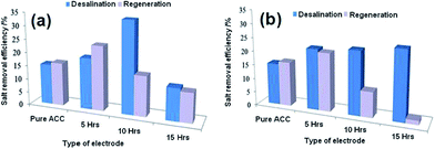 |
| | Fig. 17 Desalination and regeneration efficiency of the electrodes obtained (a) with pretreatment and (b) under controlled pH conditions. (Reproduced with permission from ref. 115.) | |
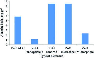 |
| | Fig. 18 Adsorbed salt on the different types of electrodes during the desalination process in 100 ppm NaCl solution under an applied potential of 1.2 V. (Reproduced with permission from ref. 116.) | |
3.3 Nanoporous carbon (NC)–MnO2 composite
Zou et al.117 developed a novel NC–MnO2 composite electrode for CDI applications. The NC was prepared by the replication of a porous silica template in a solution composed of triblock polymer P123 poly(ethyleneglycol)–poly(propyleneglycol)–poly(ethyleneglycol) ethanol and sulphuric acid with subsequent carbonization at 850 °C. The silica template was finally removed using HF. A co-precipitation method that involved a redox reaction in an aqueous solution containing KMnO4, MnSO4, NaOH and NC was exploited to synthesize the NC–MnO2 composite. During preparation, two types of silica with pore sizes of 4 nm and 2.7 nm were adopted and the obtained NC and NC–MnO2 samples were denoted as CA, CB, CA-Mn and CB-Mn, respectively. A disordered but cross-linked porous structure was observed from pure NC and needle-shaped MnO2 was observed on the surface of the NC in sample CA-Mn, as shown in Fig. 19(a) and (b). The pore size of the silica template was determined to have a large effect on the porous structure of the NC–MnO2 composites. CA-Mn possessed more mesopores but a lower surface area than CB-Mn. It was noted that the MnO2 particles could be formed on both the internal and external surfaces of the porous carbon matrix. For CA-Mn, the MnO2 was deposited on the internal surface, and therefore blocked the pores in the carbon matrix, while the main porous structure remained. Therefore, CA-Mn exhibited a decreased surface area when compared with CA. In the case of CB-Mn, the external deposition of MnO2 leads to a rise in the surface area in comparison with CB. The CDI performance of the CA-Mn, CB-Mn and AC electrodes was investigated using a flow through system at a flow rate of 20 mL min−1 in 50 mL of NaCl solution with an initial conductivity of 50 μS cm−1. The total mass of the electrode materials and applied voltage were 2 g and 1.2 V, respectively. The salt removal capacity of CA-Mn (0.99 mg g−1) and CB-Mn (0.95 mg g−1) were considerably higher than that of AC (0.32 mg g−1). The enhanced CDI performance could be attributed to the following reasons: (i) the amount of mesopores, which play a vital role in the electrosorption of ions in the NC–MnO2 composites was considerably higher than that in AC; (ii) two commonly accepted charge storage mechanisms of MnO2 including the adsorption/desorption process of protons or alkaline cations on the MnO2 surface and intercalation/deintercalation of protons or alkaline cations accompanied by the Faradic reaction greatly contributed to the electrosorption. Although a Faradic reaction occurred on the surface of the NC–MnO2 composites, their full regeneration could still be achieved, as shown in Fig. 19(c) and (d), indicating the chemical stability of the composites.
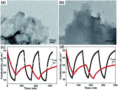 |
| | Fig. 19 TEM images of (a) CA and (b) CA-Mn; adsorption/desorption behavior of (c) CA-Mn and AC and (d) CB-Mn and AC. (Reproduced with permission from ref. 117.) | |
3.4 RG–TiO2 composite
Tang et al.50 presented a novel, simple and versatile method to fabricate 3D RG–TiO2 composites using TiCl3 and GO as the precursors by hydrothermal treatment and subsequent freeze-drying. The SEM and TEM images shown in Fig. 20(a) and (b) clearly reveal the well-defined 3D open pore nature of the RG–TiO2 product and that a large amount of TiO2 NPs were uniformly distributed on the RG sheets. The CDI performance of the RG–TiO2 composite was investigated in a continuously recycling system at a flow rate of 30 mL min−1 using 60 mL of 500 mg L−1 NaCl solution at an applied voltage of 1.2 V. As shown in Fig. 20(c), the electrosorption capacity of the composite was 15.1 mg g−1, which is 1.5 and 12.6 times of those of pure RG (9.9 mg g−1) and commercial AC (1.2 mg g−1), respectively. While, at 6000 mg L−1, the corresponding capacity is 24.2 mg g−1 for RG–TiO2, which is 1.6 and 7.3 times of that of RG (15.4 mg g−1) and AC (3.3 mg g−1), respectively. The good reversibility of the RG–TiO2 composite was confirmed by performing the desalination and regeneration process over 10 cycles (Fig. 20(d)).
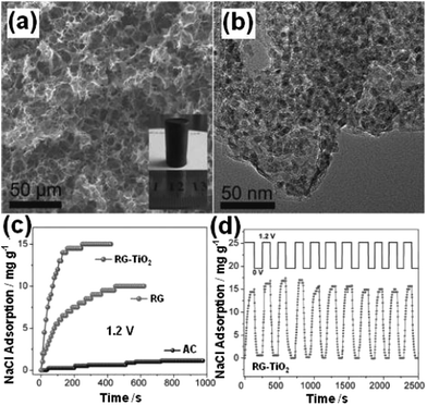 |
| | Fig. 20 (a) SEM and (b) TEM images of the RG–TiO2 composite; (c) the desalination efficiency of AC, RG and RG–TiO2 in 500 mg L−1 NaCl solution at different times; (d) electrosorption and regeneration cycles of RG–TiO2 in 500 mg L−1 NaCl solution. (Reproduced with permission from ref. 50.) | |
3.5 RG–MnO2 composite
Barakat et al.118 reported a rapid, cost-effective and eco-friendly method for preparing RG–MnO2 composites with control over their morphology by the addition of MnSO4, ammonium persulfate and piperdine during the one pot synthesis of RG. Ammonium persulfate was used as an efficient oxidizing agent for graphite and MnSO4 simultaneously with a microwave exfoliation to intercalate the formed MnO2 among the RG sheets. The shape and insertion of MnO2 nanostructures (NPs and NRs) among the RG sheets could be managed during the fabrication process by adjusting the microwave irradiation. The SEM and TEM images shown in Fig. 21(a) and (c) display the sandwich morphology of the intercalated MnO2 NPs among the RG sheets with good and uniform distribution. Fig. 21(b) and (d) show the SEM and TEM images of the MnO2 NRs@RG. Conversion of MnO2 NPs into NRs was achieved by elongation of the microwave irradiation treatment time, which resulted in sintering the synthesized NPs to form the 1D structure. The CDI experiments were conducted in a continuously recycling system using 50 mL of NaCl solution with an initial conductivity of ∼100 μS cm−1 at an applied voltage of 1.2 V. As shown in Fig. 22, the synthesized MnO2 NRs@RG reveals excellent results with a high electrosorption capacity (5.01 mg g−1), high salt removal efficiency (∼93%) and distinguished recyclability when compared to MnO2 NPs@RG, pristine RG and AC. This tremendous improvement in the salt removal was attributed to the ease of surface accessibility for ion adsorption from the saline solution to the electrode surface due to the unique morphology in addition to the electrochemical activity of MnO2.
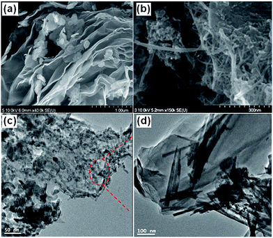 |
| | Fig. 21 SEM images of (a) MnO2 NPs@RG and (b) MnO2 NRs@RG; TEM images of (c) MnO2 NPs@RG and (d) MnO2 NRs@RG. (Reproduced with permission from ref. 118.) | |
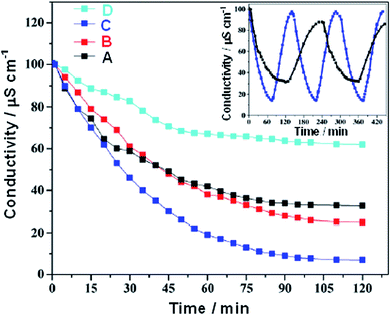 |
| | Fig. 22 CDI performance of the various electrode materials in NaCl solution at 1.2 V. (A) RG, (B) MnO2 NPs@RG, (C) MnO2 NRs@RG and (D) AC. The inset depicts the regeneration profiles for the RG and MnO2 NRs@RG electrodes. (Reproduced with permission from ref. 118.) | |
4 Carbon–polymer composite
Similar to metal oxides, a conducting polymer can contribute the pseudo-capacitance, which can largely enhance the capacitive performance of carbon materials for supercapacitor or CDI applications.119–121 Furthermore, on one hand, when these polymers are combined with carbon materials the functional groups, typically oxygen- and nitrogen-containing groups, in these polymers exhibit a high affinity to metal ions by chelation or redox reactions,122,123 which is advantageous to the electrosorption of metal ions. On the other hand, the charging and discharging processes of conducting polymers are accompanied by ion exchange between the polymer and the electrolyte that occurs in the interior of the electrode (not just on the surface),124 which can improve the adsorption capacity.
4.1 Carbon–chitosan (CS) composite
CS as an inexpensive, widely used, hydrophilic and non-toxic polysaccharide biopolymer exhibits a high specificity towards metal ions due to its abundant number of amino and hydroxyl functional groups.125,126 Therefore, CS was utilized to modify the carbon electrodes for electrosorption of ions.
4.1.1 ACFs–CS composite. Huang and Su127 reported the modification of ACFs cloth with CS and their application in the removal of Cu2+ ions from wastewater by adsorption/electrosorption. The ACFs–CS composite was obtained via an immersion of ACFs in CS solution with a CS content of about 3.0 wt%. A conventional 3D electrode static state system was adopted in the adsorption/electrosorption investigation at both open circuit and 0.3 V bias potential in Cu(NO3)2 solution. The initial concentration of the Cu2+ ions in the solution ranged from 40 to 200 mg L−1. A piece of ACFs cloth connected by a titanium plate acted as the working electrode and the initial pH of the test solution was adjusted to 4.0. The results revealed that the ACFs–CS composite possessed a higher Cu2+ ion adsorption and electrosorption capacity when compared with ACFs cloth. The reason was attributed to the ion-exchange mechanism of Cu2+ ions with H+ ions protonating the amine end groups of CS. Moreover, the existing carboxyl and hydroxyl functional groups on the surface of the composite could also promote the adsorption of inorganic ions in solution via an ion-exchange reaction.
4.1.2 CNTs–CS composite. Pan et al.59 proposed a CNTs–CS composite electrode for the electrosorption of Cu2+ ions. The composite electrode was prepared by first reacting HNO3-oxidized CNTs with thionyl chloride, and then covalently grafting CS onto the surface of the CNTs. From the SEM images of the CNTs and CNTs–CS shown in Fig. 23(a) and (b), it can be observed that the CNTs–CS displays a more compact surface in which wire-like CNTs are dispersed in the CS matrix. The TEM images show that the CNTs in the CNTs–CS composite are considerably shorter than in the pristine CNTs due to treating the CNTs with HNO3.128 The shorter CNTs might contribute to the higher specific surface area of CNTs–CS (52.7 m2 g−1) than that found with pristine CNTs (44.5 m2 g−1), which was beneficial to the removal of Cu2+. The CS functionalization of CNTs was found to lower the point of zero charge and improve the surface hydrophilicity, which could enhance the electrostatic adsorption of Cu2+, and therefore increase the removal efficiency. The electrosorption experiments were carried out in a continuously recycling system at a flow rate of 40 mL min−1 using CuCl2 solutions with an initial conductivity of 50 μS cm−1. A direct voltage of 1.2 V was applied. The variation in solution conductivity with time was recorded (Fig. 23(c)) and it was clear that no obvious physical adsorption was observed for both CNTs and CNTs–CS. The CNTs–CS presents an 85% Cu2+ removal ratio, which is 25% higher than that of the CNTs (60%). The low Cu content (0.29 at%) on the CNTs–CS after the experiment obtained by X-ray photoelectron spectroscopy indicated that electrodeposition did not occur remarkably due to the intrinsic resistance of the electrodes that consumes some voltage and electrosorption was mainly responsible for the removal of Cu2+. The kinetics of the electrosorption process for CNTs and CNTs–CS studied using a pseudo-first-order kinetics equation (Fig. 23(d)) shows that when compared with CNTs, the CNTs–CS exhibit a higher kinetic rate constant, which is beneficial to the removal of Cu2+. The stability of the CNTs–CS electrode was also verified after 30 charge–discharge cycles without any apparent decay in the removal efficiency of Cu2+.
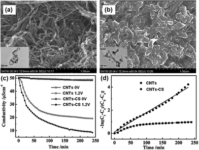 |
| | Fig. 23 SEM images of (a) CNTs and (b) CNTs–CS. The insets are their TEM images. (c) Variation of solution conductivity with time and (d) linear plot of the pseudo-first-order kinetic equation for the electrosorption of Cu2+ by CNTs and CNTs–CS. (Reproduced with permission from ref. 59.) | |
4.2 Carbon–RF composite
Hao and co-workers129,130 proposed a RG and resol (RG–RF) composite as the CDI electrode material for the removal of FeCl3 and NaCl. The procedure for synthesizing the RG–RF composite is described as follows: resorcinol, formaldehyde and sodium carbonate catalyst in a ratio of 200![[thin space (1/6-em)]](https://www.rsc.org/images/entities/char_2009.gif) :
:![[thin space (1/6-em)]](https://www.rsc.org/images/entities/char_2009.gif) 400
400![[thin space (1/6-em)]](https://www.rsc.org/images/entities/char_2009.gif) :
:![[thin space (1/6-em)]](https://www.rsc.org/images/entities/char_2009.gif) 1 were slowly added to a GO solution. Then, the solution was transferred to a Teflon-lined autoclave and maintained at 85 °C for 3 days. The mixture was reduced by calcination at 900 °C under an N2 atmosphere, resulting in the RG–RF composite. Fig. 24 shows the TEM and SEM images of GO and the RG–RF composite. It can be observed that the RF entangles with RG to form a good network structure. The introduction of RF largely enhances the specific surface area. The electrosorption experiments were conducted in a continuously recycling system using RG–FR, RG and AC electrodes. The mass and size of the electrodes were 1.5 g and 70 mm × 140 mm, respectively. The FeCl3 and NaCl solutions with a volume of 200 mL were employed as the feed solution, respectively, and the flow rate was 20 mL min−1. As shown in Fig. 25(a) and (b), the electrosorption capacity of the RG–RF electrode was 3.47 mg g−1 in 40 mg L−1 FeCl3 solution and 2.135 mg g−1 in 40 mg L−1 NaCl solution at an electrical voltage of 2.0 V, higher than those of the AC (1.41 and 0.612 mg g−1) and RG (2.46 and 1.510 mg g−1) electrodes due to the presence of RF, which is beneficial in restricting the aggregation of RG, resulting in a high specific surface area. As for the AC electrode, despite its higher specific surface area than that of RG–RF, its larger micropore volume and smaller average pore size is not beneficial for electrosorption and results in a low electrosorption capacity.
1 were slowly added to a GO solution. Then, the solution was transferred to a Teflon-lined autoclave and maintained at 85 °C for 3 days. The mixture was reduced by calcination at 900 °C under an N2 atmosphere, resulting in the RG–RF composite. Fig. 24 shows the TEM and SEM images of GO and the RG–RF composite. It can be observed that the RF entangles with RG to form a good network structure. The introduction of RF largely enhances the specific surface area. The electrosorption experiments were conducted in a continuously recycling system using RG–FR, RG and AC electrodes. The mass and size of the electrodes were 1.5 g and 70 mm × 140 mm, respectively. The FeCl3 and NaCl solutions with a volume of 200 mL were employed as the feed solution, respectively, and the flow rate was 20 mL min−1. As shown in Fig. 25(a) and (b), the electrosorption capacity of the RG–RF electrode was 3.47 mg g−1 in 40 mg L−1 FeCl3 solution and 2.135 mg g−1 in 40 mg L−1 NaCl solution at an electrical voltage of 2.0 V, higher than those of the AC (1.41 and 0.612 mg g−1) and RG (2.46 and 1.510 mg g−1) electrodes due to the presence of RF, which is beneficial in restricting the aggregation of RG, resulting in a high specific surface area. As for the AC electrode, despite its higher specific surface area than that of RG–RF, its larger micropore volume and smaller average pore size is not beneficial for electrosorption and results in a low electrosorption capacity.
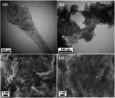 |
| | Fig. 24 TEM images of (a) GO and (b) RG–RF; SEM images of (c) GO and (d) RG–RF. (Reproduced with permission from ref. 130.) | |
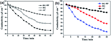 |
| | Fig. 25 Comparative results of RGO–RF, RGO and AC electrodes in terms of electrosorption performance in (a) 40 mg L−1 FeCl3 solution and (b) 40 mg L−1 NaCl solution. (Reproduced with permission from ref. 129 and 130.) | |
4.3 Carbon–polyaniline (PANI) composite
Zou et al.119 synthesized single-walled CNTs (SWCNTs) and PANI composites by in situ polymerization of aniline in a CNTs suspension. From the TEM images shown in Fig. 26(a) and (b), it can be clearly observed that PANI polymerizes along the SWCNTs, with the SWCNTs as the core wrapped in a layer of PANI. Packing of PANI outside the SWCNTs causes an increase in mesopore volume, which is beneficial to CDI performance. The CDI tests were carried out in a continuously recycling system using NaCl solution with an initial conductivity of 100 μS cm−1 at a flow rate of 20 mL min−1. A direct voltage of 1.2 V was applied. The mass and size of the electrodes were 1.34 g and 70 mm × 140 mm, respectively. The CNTs–PANI composite electrode demonstrates a higher electrosorption capacity and better recyclability than those of the CNTs electrode, as shown in Fig. 26(c) and (d). The π–π conjugated interaction between the PANI backbone and the graphite-like structure of the CNTs, which facilitate ion transport, should also contribute to the enhanced CDI performance.
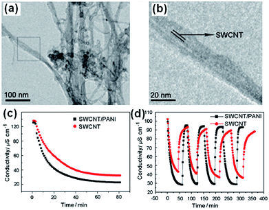 |
| | Fig. 26 (a) Low magnification and (b) high magnification TEM images of the CNTs–PANI composite; (c) CDI performance and (d) adsorption/desorption cycles for the CNTs–PANI composite. (Reproduced with permission from ref. 119.) | |
4.4 Carbon-ion exchange polymer composite
In addition to the electrode materials, some other factors during the electrosorption process, such as the co-ion expulsion effect, can significantly influence CDI performance.131 When an electric potential is applied between the electrodes, counter-ion adsorption and co-ion expulsion effects happen simultaneously, which leads to a poor charge efficiency. This problem becomes worse with an increasing concentration.132 Therefore, coulomb inefficiency has become a major problem that limits CDI applications. Andelman et al.133 proposed an effective method by introducing a charge barrier membrane into CDI, called membrane capacitive deionization (MCDI), which has been studied by several groups in recent years.63,131,134–144 The salt removal of the MCDI system was found to be largely improved and could reach even ∼50% higher than that of the CDI system.131,135,141,145 However, an issue associated with the introduction of the ion exchange membranes should be noted. The weak contact adhesion between the electrodes and the ion-exchange membranes might produce contact resistance and increase the bulk resistivity of the entire unit, which would increase energy consumption and decrease ion adsorption. To overcome this problem, ion exchange polymers were proposed to replace the ion exchange membranes in MCDI devices.140,142,146,147
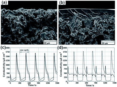
Kim and Choi140,142 first proposed a novel carbon electrode coated with a cation-exchange polymer for CDI. The composite electrode was prepared by casting a polymer solution containing 10 wt% poly(vinyl alcohol) and 30 wt% sulfosuccinic acid (SSA) onto an AC electrode and heating the electrode at 130 °C for 1 h. The SSA acted as a crosslinking agent and provided ion-exchange functional groups. The SEM images in Fig. 27(a) and (b) show that the ion-exchange polymer is well coated on top of the carbon electrode. The prepared composite electrode integrates both the advantages of high capacitance from the carbon electrode and the permselectivity of the ion-exchange polymer. According to electrochemical impedance spectroscopy measurements, it was found that the equivalent series resistance for the coated electrode was higher than that of uncoated electrode but the resistance of the coating layer was relatively low when compared to commercial ion-exchange membranes. The CDI experiments were performed in a flow-through system with a feed NaCl solution of 200 mg L−1. The size of the electrodes was 100 mm × 100 mm. Desalination curves for the CDI cell and MCDI cell (one uncoated and one coated-carbon electrode) at a voltage of 1.2 V are shown in Fig. 27(c). It can be seen that the desalination efficiency can be enhanced using a carbon electrode coated with an ion-exchange polymer. When compared with the CDI cell, the desalination efficiency and current efficiency of the MCDI cell are enhanced by about 27–56% and 69–95%, respectively relying on the operating conditions. In the MCDI cell, anions in the bulk solution cannot penetrate through the cation-exchange layer and desorption of the absorbed cations was restrained, which thereby improved the CDI performance. The selectivity of the coated electrode was further verified by conducting the desalination experiment in the MCDI cell at a potential of −1.5 V, in which the coated electrode acted as the anode. As seen from Fig. 27(d), few ions are electroabsorbed and desorbed in the MCDI cell due to anion rejection by the cation-exchange layer of the coated electrode, which demonstrates that the coated cation-exchange layer functions well to selectively transport ions.
 |
| | Fig. 27 SEM images of (a) uncoated carbon electrodes and (b) carbon electrodes coated with an ion-exchange polymer; the conductivity transient of effluent measured at a cell potential of (c) 1.2 V with a flow rate of 20 mL min−1 and (d) −1.5 V with a flow rate of 20 mL min−1. Solid line: MCDI cell, dashed line: CDI cell. (Reproduced with permission from ref. 140.) | |
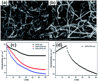
Pan et al.146 reported a CNTs–polyacrylic acid (PAA) composite film electrode for CDI applications. The CNTs–PAA composite film electrode was fabricated via an electrophoretic deposition method in PAA solution containing the CNTs. The PAA served as the cation-exchange polymer and matrix to incorporate the CNTs. From the SEM images of the CNTs and CNTs–PAA shown in Fig. 28(a) and (b), it can be seen that the density of CNTs in the CNTs–PAA composite was lower than that in the pure CNTs indicating that the CNTs are well dispersed in the PAA polymer matrix. Three cells, CNTs–PAA cell assembled with one CNTs electrode and one CNTs–PAA composite electrode, CNTs cell consisting of two CNTs electrodes and a modified CNTs cell with introducing a cation-exchange membrane (CNTs–CEM cell), were tested in a continuously recycling system at a flow rate of 40 mL min−1. The effective area of the electrodes was 8 cm × 8 cm. NaCl solution with an initial conductivity of 50 μS cm−1 was used as feed solution and a direct voltage of 1.2 V was applied. The result is shown in Fig. 28(c). Among the three cells, the CNTs–PAA cell exhibits the highest NaCl removal of 83%, 51% higher than that of the CNTs cell (32%) and 12% higher than that of the CNTs–CEM cell (71%), which is similar to the other report.140 Furthermore, the cation selectivity of the CNTs–PAA composite film electrode was confirmed by the observation of no obvious electrosorption when the CNTs–PAA cell was operated under a voltage of −1.2 V, as shown in Fig. 28(d).
 |
| | Fig. 28 SEM images of (a) CNTs and (b) CNTs–PAA composite electrodes; (c) electrosorption process for the CNTs cell, CNTs–PAA cell and CNTs–CEM cell; (d) electrosorption behavior for the CNTs–PAA cell under an applied voltage of −1.2 V. (Reproduced with permission from ref. 146.) | |
In the above work, the enhanced desalination efficiency was attributed to the selective transport of cations from bulk solution to the electrode surface due to the presence of the cation-exchange polymer. However, the research on the anion-exchange polymer is far from enough compared with its cation partner. Therefore, in view of their practical applications, investigations on the MCDI cell employing both anion and cation exchange polymers to replace the anion and cation exchange membranes are necessary.
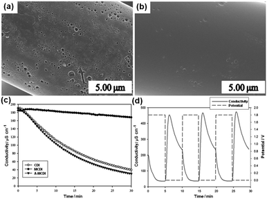
Moon et al.147 achieved some progress on this issue. They studied an advanced MCDI (A-MCDI) by adhering both the cation exchanger and anion exchanger (sulfonation and amination of bromomethylated poly(2,6-dimethyl-1,4-phenylene oxide) (BPPO)) onto the surface of carbon cloth electrodes. The electrodes were prepared in two steps: spraying the BPPO slurry onto the surface of carbon cloth, and then immersing the electrodes in sulfuric acid solution or trimethylamine solution to complete the sulfonation or amination reaction. From the SEM images shown in Fig. 29(a) and (b), it was found that the clean surface and the pores on the CFs of the original carbon cloth are filled with the polymer. The desalination experiments using CDI, MCDI and A-MCDI cells were carried out in a continuously recycling system at a flow rate of 4 mL min−1. 100 mg L−1 NaCl solution was used as the feed solution and a direct voltage of 1.8 V was applied. As shown in Fig. 29(c), it is clearly observed that the A-MCDI cell shows the highest removal efficiency of 83.4% but only a little enhancement (4.3%) is achieved when compared with the CDI device. Different from the results reported by other groups,135,141,145 the MCDI cell (9.23%) exhibits a considerably lower desalination efficiency than the CDI cell (79.1%). Moon et al. attributed this to the contact resistance and membrane resistance. The good stability of the A-MCDI cell was verified using a cyclic desalination test (Fig. 29(d)).
 |
| | Fig. 29 SEM images of (a) the bare carbon cloth surface and (b) the embedded carbon electrode surface; (c) variations in the ion conductivity of the CDI, MCDI and A-MCDI during their operation; (d) continuous mode operation of the A-MCDI system by repeated adsorption and desorption cycles. (Reproduced with permission from ref. 147.) | |
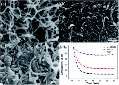
Recently, Pan et al.144 further developed a modified MCDI (m-MCDI) device based anion and cation exchange polymers. Polyethyleneimine (PEI) and dimethyldiallyl ammonium chloride (DMDAAC) were used as the cation and anion exchange polymers, respectively, and incorporated into the CNTs electrodes using a casting method. From the SEM images in Fig. 30(a)–(c), it can be observed that the CNTs–PEI and CNTs–DMDAAC electrodes display compact surfaces compared to the CNTs electrode and the wire-like CNTs are dispersed in the PEI or DMDAAC matrix. The CDI experiments were carried out in a continuously recycling system at a flow rate of 50 mL min−1. The size of all the electrodes was 8 cm × 8 cm and the average mass of the electrodes was 905 mg. The m-MCDI unit cell based on both anion and cation exchange polymers exhibits a high NaCl removal of 93%, much higher than that of the conventional CDI cell with the CNTs electrode (25%) or the MCDI cell with commercial anion and cation exchange membranes (74%) in a certain experiment at 1.2 V and for an initial conductivity of 50 μS cm−1, as shown in Fig. 30(d). The electrosorption behavior of the m-MCDI and MCDI cells in NaCl solution with an initial conductivity of 1000 μS cm−1 at a voltage of 2 V was also investigated and their electrosorption capacity were 9.3 and 6.67 mg g−1, respectively. The large improvement in desalination performance was mainly due to the reduced co-ion expulsion effect by introducing the ion exchange polymers and the better contact adhesion between the ion exchange polymers and electrodes than that found between commercial ion exchange membranes and electrodes.
 |
| | Fig. 30 SEM images of the (a) CNTs, (b) CNTs–PEI and (c) CNTs–DMDAAC electrodes; (d) electrosorption process for the CDI, MCDI, m-MCDI cells. (Reproduced with permission from ref. 144.) | |
Despite the progress to date, there are still two problems that need to be solved: (i) when a polymer is mixed too deeply into the electrode, due to differential swelling of the two materials, it may lead to fracturing of the carbon pores and also these separate materials still have a resistive component that is unfavourable for the CDI process, and (ii) no matter if the MCDI is based on membranes or polymers, there still exists a concentrated solution trapped behind the membranes/polymers, as found in ED. In order to solve these problems, Andelman et al.132 developed ionic group derivatized nanoporous carbon electrodes. In their methodology the problem of charge efficiency was settled by modifying the electrode material itself, which could prevent the solution from being trapped. The ionic group derivatized nanoporous carbon electrodes were prepared according to the following steps: two activated carbon electrodes were separately soaked in sodium dodecyl sulfate and hexadecyltrimethylammonium aqueous solutions for one month, and then washed in water. The CDI tests were carried out using a 0.1 M NaCl feed solution at a flow rate of 20 mL min−1. A direct voltage of 1.2 V was applied. As shown in Fig. 31, the charge efficiency of the flow through capacitor cell based on ionic group derivatized nanoporous carbon electrodes charged in the positive polarity was 70% with a product solution electrosorption capacity of 10.5 mg g−1, which is considerably higher than those of the scientific control capacitor without the attached ionic groups.
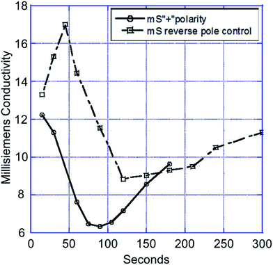 |
| | Fig. 31 Electrosorption process for the capacitor based on an ionic group derivatized nanoporous carbon electrode charged in the positive polarity and scientific control capacitor (Reproduced with permission from ref. 132.) | |
5 Carbon–polymer–metal oxide composite
Although the MCDI technology integrating the ion-exchange polymer and carbon electrode into one structure is considered to deliver economical desalination performance, the further reduction of the electrical resistance of the polymer coating layer while maintaining the ion selectivity of the electrodes is important for improving the desalination efficiency. Lee and Choi developed a composite electrode by coating a mixture of metal-oxide (TiO2) NPs and ion-exchange polymers (sulfonated polystyrene) onto the AC electrode surface.148 The TiO2 could be effective at maintaining the ion selectivity of the electrodes because their surfaces were charged, while the electrical resistance of the coating layer was thought to be reduced by the formation of miscellaneous pores among the TiO2 NPs. The optimal content of TiO2 in the carbon composite electrodes, in terms of electrical resistance and ion selectivity, was found to be approximately 10 wt%. The desalination performance of the composite electrodes (10 cm × 10 cm) was investigated in a 200 mg L−1 NaCl solution at a flow rate of 20 mL min−1 and a potential of 1.2 V, and the desalination efficiency of the composite carbon electrodes was improved by approximately 30% over that of an unmodified carbon electrode.
In summary, we have introduced various carbon-based composite electrodes. In addition to these above-mentioned materials, other composites, such as CNTs–polystyrene sodium sulfonate–MnO2,149 RG–PANI,150 GO–CNFs,151 CFs–SiO2/γ-Al2O3,152 CFs–RG,153 and CAs–silica154 have also been studied for CDI or MCDI applications. Table 1 lists the electrochemical and electrosorption performances of different carbon-based electrodes reported in the literature. As seen, the electrosorption performance of these materials is highly related to both the electrochemical factors and the initial concentration, which is in accordance with the findings in ref. 132. The electrosorption capacity varies from 0.13 to ∼17 mg g−1, and most of the composite materials exhibit superior desalination performance when compared to their single component carbon materials.
Table 1 Comparison of the electrochemical and electrosorption performance among different carbon-based electrode materials reported in the literature
| Electrode material |
Electrochemical performance |
Electrosorption performance (in NaCl solution) |
Ref. |
| Specific capacitance (F g−1)/scan rate (mV s−1) |
Applied voltage (V) |
Initial concentration (mg L−1) |
Electrosorption capacity (mg g−1) |
Charge efficiency |
| CAs |
— |
1.2 |
50 |
1.4 |
— |
23 |
| |
1.2 |
500 |
2.9 |
— |
|
| |
1.2 |
58.5 |
1.34 |
— |
161 |
| — |
1.2 |
140 |
4.51 |
— |
|
| AC |
— |
1.5 |
200 |
3.70 |
— |
141 |
| — |
1.2 |
292 |
10.90 |
∼0.85 |
26 |
| — |
1.4 |
1170 |
13.00 |
|
|
| — |
1.2 |
292 |
10.50 |
— |
162 |
| — |
1.2 |
292 |
6.90 |
∼0.85 |
15 |
| — |
1.4 |
292 |
8.40 |
|
|
| 169/1 |
1.2 |
∼25 |
0.25 |
— |
42 |
| 108/1 |
1.2 |
∼50 |
0.27 |
— |
163 |
| — |
1.2 |
100 |
6.10 |
— |
33 |
| — |
1.2 |
200 |
8.00 |
— |
|
| — |
1.2 |
500 |
9.72 |
— |
|
| — |
1.2 |
1000 |
10.80 |
— |
|
| — |
1.2 |
1500 |
11.00 |
— |
|
| — |
1.2 |
2000 |
11.76 |
— |
|
| — |
1.2 |
60 |
0.13 |
— |
108 |
| CNTs |
— |
1.2 |
3000 |
1.7 |
— |
62 |
| — |
2.0 |
23 |
1.3 |
— |
61 |
| — |
1.2 |
60 |
0.7 |
|
37 |
| — |
1.2 |
500 |
2.57 |
|
|
| — |
1.2 |
1000 |
3.71 |
|
40 |
| — |
1.2 |
1500 |
4.76 |
— |
|
| — |
1.2 |
2000 |
5.24 |
— |
|
| CNFs |
— |
1.2 |
60 |
3.2 |
— |
37 |
| 228/2 |
1.6 |
95 |
4.6 |
— |
38 |
| MC |
251/1 |
1.2 |
25 |
0.68 |
— |
42 |
| 192/1 |
0.8 |
50 |
0.93 |
— |
163 |
| CNTs–MC |
— |
1.2 |
40 |
0.63 |
— |
65 |
| 132.6/10 |
1.2 |
40 |
0.69 |
— |
66 |
| CNTs–CNFs |
— |
1.2 |
∼50 |
3.32 |
— |
27 and 70 |
| RG–AC |
181/1 |
1.2 |
∼500 |
2.94 |
0.24 |
90 |
| RG–MC |
89.6/1 |
2.0 |
∼45 |
0.73 |
— |
91 |
| RG@MC sphere |
43.2/10 |
1.6 |
∼34 |
2.3 |
— |
164 |
| RG–CNTs |
175/1 |
2.0 |
∼27 |
1.41 |
— |
68 |
| 220/5 |
2.0 |
∼770 |
26.42 |
— |
165 |
| 311.1/10 |
1.6 |
∼50 |
0.88 |
— |
93 |
| RG–CNTs aerogel |
— |
1.6 |
4000 |
79.4 |
— |
96 |
| |
1.0 |
35![[thin space (1/6-em)]](https://www.rsc.org/images/entities/char_2009.gif) 000 000 |
633.3 |
— |
|
| ACF–CNFs |
29.2/10 |
1.2 |
∼25 |
17.19 |
— |
102 |
| ACF–CB |
— |
1.6 |
90 |
9.13 |
— |
101 |
| AC-TiO2 |
84.7/10 |
1.2 |
100 |
8.05 ± 0.34 |
— |
111 |
| 104/2 |
1.2 |
584.4 |
17 |
— |
114 |
| AC–ZnO |
95/1 |
1.2 |
100 |
8.5 |
— |
116 |
| AC–MnO2 |
77.2/10 |
1.2 |
∼25 |
0.99 |
— |
149 |
| RG–TiO2 |
119.7/100 |
1.2 |
500 |
15.1 |
— |
50 |
| |
1.2 |
6000 |
24.2 |
— |
|
| RG–RF |
135.7/10 |
2.0 |
40 |
2.14 |
— |
129 |
| CNTs–PEI–DMDAAC |
52.6/5 |
2.0 |
1000 |
9.3 |
0.70 |
144 |
| Polarized porous carbon |
20.5/— |
1.2 |
∼5850 |
10.5 |
0.70 |
132 |
6 Prospects
CDI, as a rising star, has attracted more and more attention in recent years due to its energy- and cost-saving advantages over traditional water treatment technologies in the application of desalination. However, there are some issues that should be taken into account, otherwise, it will limit the applications of CDI. One of the most key issues is related to the electrode materials. During CDI operation, the electrosorption capacity is closely associated with the accessibility, stability, permeability and surface properties. It is important to note that in the carbon–metal oxide composites, the stability of the metal oxide in the aqueous solution under potential is critical for electrode performance. Furthermore, water electrolysis and other parasitic redox reactions (such as the reduction of oxygen dissolved in the water, oxidation of the carbon surface and oxidation of Cl− ions to chlorine gas) may take place more easily when using the carbon–metal oxide composite materials because the metal oxide may change the potential of zero charge of the electrode to be close to the potential of the parasitic redox reactions. Therefore, the possible contamination caused by the metal oxides eroded into the purified water should be the main concern. Moreover, the MCDI system with high charge efficiency and desalination efficiency is promising for practical applications of CDI. However, the introduction of ion-exchange membranes can result in high resistance, high cost and expansion of the cell dimensions. Integrating ion-exchange polymers with carbon electrodes can help to alleviate these problems. Hence, more studies on this issue are required in order to perfect the replacement of ion-exchange membranes by carbon–polymer composite electrodes.
Another problem faced by CDI technology is that although the composite electrode materials were proposed to improve the salt removal by CDI, the treatment of highly concentrated salt water such as seawater is still difficult. This is because of the low charge efficiency132,134 caused by the inaccessible pore volume and the co-ion expulsion effect. In addition, this problem becomes worse with an increasing concentration. Recently, a new form of CDI structure, which employs a flow electrode, named as FCDI, has been proposed to realize the desalination of seawater.155–157 This particular design uses suspended carbon electrode instead of a traditional fixed electrode, which allows the ions to flow through a flow path between the ion-exchange membrane and the current collector, with the salt water running through a spacer. This design makes sure that the carbon particles are fully exposed to the salt ions to fix the problem of low charge efficiency in a certain degree. Preliminary results have shown that FCDI is a highly efficient design even in high salinity. However, further exploration on suitable flow electrodes, especially the composite with high electrosorption capacity should be a key in the future study of FCDI.
As a versatile technology CDI can also be used for the extraction of heavy metal ions or fluoride, nitrate and phosphate from aquatic resources. A new feature of CDI is the selective removal of specific ions by composite electrodes showing specific adsorption for heavy metal ions or calcium ions can be possibly fabricated in the future.158–160 In the foreseeable future, selective adsorption of target ions should be a concern in CDI research.
In summary, CDI is a promising desalination technology and shows a bright future despite its related challenges. With a continuous search for solutions to these challenges, CDI or its advanced versions may be considered as key to the worldwide water shortage in the future.
Acknowledgements
Financial support from the National Natural Science Foundation of China (no. 21276087) is gratefully acknowledged.
Notes and references
- S. J. Kim, S. H. Ko, K. H. Kang and J. Han, Nat. Nanotechnol., 2010, 5, 297–301 CrossRef CAS PubMed
 .
. - M. Elimelech and W. A. Phillip, Science, 2011, 333, 712–717 CrossRef CAS PubMed
 .
. - T. Humplik, J. Lee, S. O'Hern, B. Fellman, M. Baig, S. Hassan, M. Atieh, F. Rahman, T. Laoui and R. Karnik, Nanotechnology, 2011, 22, 292001 CrossRef CAS PubMed
 .
. - M. A. Anderson, A. L. Cudero and J. Palma, Electrochim. Acta, 2010, 55, 3845–3856 CrossRef CAS PubMed
 .
. - S. Zhao, L. Zou, C. Y. Tang and D. Mulcahy, J. Membr. Sci., 2012, 396, 1–21 CrossRef CAS PubMed
 .
. - H. Strathmann, Desalination, 2010, 264, 268–288 CrossRef CAS PubMed
 .
. - M. Pasta, C. D. Wessells, Y. Cui and F. La Mantia, Nano Lett., 2012, 12, 839–843 CrossRef CAS PubMed
 .
. - M. Mehanna, T. Saito, J. Yan, M. Hickner, X. Cao, X. Huang and B. E. Logan, Energy Environ. Sci., 2010, 3, 1114–1120 CAS
 .
. - S. Porada, R. Zhao, A. Van Der Wal, V. Presser and P. Biesheuvel, Prog. Mater. Sci., 2013, 58, 1388–1422 CrossRef CAS PubMed
 .
. - M. E. Suss, T. F. Baumann, W. L. Bourcier, C. M. Spadaccini, K. A. Rose, J. G. Santiago and M. Stadermann, Energy Environ. Sci., 2012, 5, 9511–9519 CAS
 .
. - K. Foo and B. Hameed, J. Hazard. Mater., 2009, 170, 552–559 CrossRef CAS PubMed
 .
. - W. Huang, Y. M. Zhang, S. X. Bao and S. X. Song, Surf. Rev. Lett., 2013, 20, 1330003 CrossRef
 .
. - D. Qi, L. Zou and E. Hu, Res. J. Chem. Environ., 2007, 11, 92–95 CAS
 .
. - Y. Zhao, Y. Wang, R. Wang, Y. Wu, S. Xu and J. Wang, Desalination, 2013, 324, 127–133 CrossRef CAS PubMed
 .
. - S. Porada, L. Weinstein, R. Dash, A. Van Der Wal, M. Bryjak, Y. Gogotsi and P. Biesheuvel, ACS Appl. Mater. Interfaces, 2012, 4, 1194–1199 CAS
 .
. - L. Wang, M. Wang, Z. H. Huang, T. Cui, X. Gui, F. Kang, K. Wang and D. Wu, J. Mater. Chem., 2011, 21, 18295–18299 RSC
 .
. - S. Seo, H. Jeon, J. K. Lee, G. Kim, D. Park, H. Nojima, J. Lee and S. Moon, Water Res., 2010, 44, 2267–2275 CrossRef CAS PubMed
 .
. - F. A. AlMarzooqi, A. A. A. Ghaferi, I. Saadat and N. Hilal, Desalination, 2014, 342, 3–15 CrossRef CAS PubMed
 .
. - E. Avraham, M. Noked, A. Soffer and D. Aurbach, Electrochim. Acta, 2011, 56, 6312–6317 CrossRef CAS PubMed
 .
. - A. Johnson and J. Newman, J. Electrochem. Soc., 1971, 118, 510–517 CrossRef CAS PubMed
 .
. - G. Murphy and D. Caudle, Electrochim. Acta, 1967, 12, 1655–1664 CrossRef CAS
 .
. - J. Farmer, D. Fix, G. Mack, R. Pekala and J. Poco, J. Appl. Electrochem., 1996, 26, 1007–1018 CrossRef CAS
 .
. - J. C. Farmer, D. V. Fix, G. V. Mack, R. W. Pekala and J. F. Poco, J. Electrochem. Soc., 1996, 143, 159–169 CrossRef CAS PubMed
 .
. - T. Kim, J. Dykstra, S. Porada, A. van der Wal, J. Yoon and P. M. Biesheuvel, J. Colloid Interface Sci., 2014 DOI:10.1016/j.jcis.2014.08.041
 .
. - P. M. Biesheuvel, Y. Fu and M. Z. Bazant, Russ. J. Electrochem., 2012, 48, 580–592 CrossRef CAS
 .
. - R. Zhao, P. Biesheuvel, H. Miedema, H. Bruning and A. Van der Wal, J. Phys. Chem. Lett., 2010, 1, 205–210 CrossRef CAS
 .
. - H. B. Li, L. K. Pan, C. Y. Nie and Z. Sun, J. Nanosci. Lett., 2012, 2, 9 Search PubMed
 .
. - P. Xu, J. E. Drewes, D. Heil and G. Wang, Water Res., 2008, 42, 2605–2617 CrossRef CAS PubMed
 .
. - I. Villar, S. Roldan, V. Ruiz, M. Granda, C. Blanco, R. Menendez and R. Santamaría, Energy Fuels, 2010, 24, 3329–3333 CrossRef CAS
 .
. - J. H. Choi, Sep. Purif. Technol., 2010, 70, 362–366 CrossRef CAS PubMed
 .
. - S. Porada, M. Bryjak, A. Van Der Wal and P. Biesheuvel, Electrochim. Acta, 2012, 75, 148–156 CrossRef CAS PubMed
 .
. - H. Oda and Y. Nakagawa, Carbon, 2003, 41, 1037–1047 CrossRef CAS
 .
. - Z. Chen, C. Song, X. Sun, H. Guo and G. Zhu, Desalination, 2011, 267, 239–243 CrossRef CAS PubMed
 .
. - E. Avraham, M. Noked, Y. Bouhadana, A. Soffer and D. Aurbach, Electrochim. Acta, 2010, 56, 441–447 CrossRef CAS PubMed
 .
. - H. Oh, J. Lee, H. Ahn, Y. Jeong, Y. Kim and C. Chi, Thin Solid Films, 2006, 515, 220–225 CrossRef CAS PubMed
 .
. - Z. Huang, M. Wang, L. Wang and F. Kang, Langmuir, 2012, 28, 5079–5084 CrossRef CAS PubMed
 .
. - M. Wang, Z. Huang, L. Wang, M. Wang, F. Kang and H. Hou, New J. Chem., 2010, 34, 1843–1845 RSC
 .
. - G. Wang, C. Pan, L. Wang, Q. Dong, C. Yu, Z. Zhao and J. Qiu, Electrochim. Acta, 2012, 69, 65–70 CrossRef CAS PubMed
 .
. - C. Y. Nie, L. K. Pan, H. B. Li, T. Q. Chen, T. Lu and Z. Sun, J. Electroanal. Chem., 2012, 666, 85–88 CrossRef CAS PubMed
 .
. - S. Wang, D. Wang, L. Ji, Q. Gong, Y. Zhu and J. Liang, Sep. Purif. Technol., 2007, 58, 12–16 CrossRef CAS PubMed
 .
. - X. Wang, J. S. Lee, C. Tsouris, D. W. DePaoli and S. Dai, J. Mater. Chem., 2010, 20, 4602–4608 RSC
 .
. - L. Zou, L. Li, H. Song and G. Morris, Water Res., 2008, 42, 2340–2348 CrossRef CAS PubMed
 .
. - R. T. Mayes, C. Tsouris, J. O. Kiggans Jr, S. M. Mahurin, D. W. DePaoli and S. Dai, J. Mater. Chem., 2010, 20, 8674–8678 RSC
 .
. - C. C. Huang and J. C. He, Chem. Eng. J., 2013, 221, 469–475 CrossRef CAS PubMed
 .
. - A. G. El-Deen, N. A. Barakat, K. A. Khalil and H. Y. Kim, New J. Chem., 2014, 38, 198–205 RSC
 .
. - H. B. Li, T. Lu, L. K. Pan, Y. P. Zhang and Z. Sun, J. Mater. Chem., 2009, 19, 6773–6779 RSC
 .
. - H. B. Li, L. Zou, L. K. Pan and Z. Sun, Environ. Sci. Technol., 2010, 44, 8692–8697 CrossRef CAS PubMed
 .
. - B. P. Jia and L. Zou, Carbon, 2012, 50, 2315–2321 CrossRef CAS PubMed
 .
. - P. M. Biesheuvel, S. Porada, M. Levi and M. Bazant, J. Solid State Electrochem., 2014, 18, 1365–1376 CrossRef CAS
 .
. - H. Yin, S. Zhao, J. Wan, H. Tang, L. Chang, L. He, H. Zhao, Y. Gao and Z. Tang, Adv. Mater., 2013, 25, 6270–6276 CrossRef CAS PubMed
 .
. - S. Iijima, Nature, 1991, 354, 56–58 CrossRef CAS
 .
. - K. L. Strong, D. P. Anderson, K. Lafdi and J. N. Kuhn, Carbon, 2003, 41, 1477–1488 CrossRef CAS
 .
. - Z. Liu, X. Sun, N. Nakayama-Ratchford and H. Dai, ACS Nano, 2007, 1, 50–56 CrossRef CAS PubMed
 .
. - M. Kaempgen, C. K. Chan, J. Ma, Y. Cui and G. Gruner, Nano Lett., 2009, 9, 1872–1876 CrossRef CAS PubMed
 .
. - G. Zhu, L. K. Pan, T. Lu, X. J. Liu, T. Lv, T. Xu and Z. Sun, Electrochim. Acta, 2011, 56, 10288–10291 CrossRef CAS PubMed
 .
. - B. Corry, Energy Environ. Sci., 2011, 4, 751–759 CAS
 .
. - C. Lu, Y. Chung and K. Chang, Water Res., 2005, 39, 1183–1189 CrossRef CAS PubMed
 .
. - G. P. Rao, C. Lu and F. Su, Sep. Purif. Technol., 2007, 58, 224–231 CrossRef CAS PubMed
 .
. - Y. K. Zhan, L. K. Pan, C. Y. Nie, H. B. Li and Z. Sun, J. Alloys Compd., 2011, 509, 5667–5671 CrossRef CAS PubMed
 .
. - D. Zhang, L. Shi, J. Fang, K. Dai and X. Li, Mater. Chem. Phys., 2006, 97, 415–419 CrossRef CAS PubMed
 .
. - H. B. Li, L. K. Pan, T. Lu, Y. K. Zhan, C. Y. Nie and Z. Sun, J. Electroanal. Chem., 2011, 653, 40–44 CrossRef CAS PubMed
 .
. - K. Dai, L. Shi, J. Fang, D. Zhang and B. Yu, Mater. Lett., 2005, 59, 1989–1992 CrossRef CAS PubMed
 .
. - J. Yang, L. Zou and N. R. Choudhury, Electrochim. Acta, 2013, 91, 11–19 CrossRef CAS PubMed
 .
. - D. S. Zhang, L. Y. Shi, J. H. Fang and K. Dai, J. Mater. Sci., 2007, 42, 2471–2475 CrossRef CAS
 .
. - D. S. Zhang, L. Y. Shi, J. H. Fang and K. Dai, Mater. Lett., 2006, 60, 360–363 CrossRef CAS PubMed
 .
. - Z. Peng, D. S. Zhang, L. Y. Shi and T. T. Yan, J. Mater. Chem., 2012, 22, 6603–6612 RSC
 .
. - Z. Peng, D. S. Zhang, T. T. Yan, J. P. Zhang and L. Y. Shi, Appl. Surf. Sci., 2013, 282, 965–973 CrossRef CAS PubMed
 .
. - D. Zhang, T. Yan, L. Shi, Z. Peng, X. Wen and J. Zhang, J. Mater. Chem., 2012, 22, 14696–14704 RSC
 .
. - H. B. Li, L. K. Pan, Y. P. Zhang, L. Zou, C. Q. Sun, Y. K. Zhan and Z. Sun, Chem. Phys. Lett., 2010, 485, 161–166 CrossRef CAS PubMed
 .
. - X. Z. Wang, M. G. Li, Y. W. Chen, R. M. Cheng, S. M. Huang, L. K. Pan and Z. Sun, Appl. Phys. Lett., 2006, 89, 053127 CrossRef PubMed
 .
. - Y. Gao, L. K. Pan, H. B. Li, Y. P. Zhang, Z. J. Zhang, Y. W. Chen and Z. Sun, Thin Solid Films, 2009, 517, 1616–1619 CrossRef CAS PubMed
 .
. - L. K. Pan, X. Z. Wang, Y. Gao, Y. P. Zhang, Y. W. Chen and Z. Sun, Desalination, 2009, 244, 139–143 CrossRef CAS PubMed
 .
. - Y. Gao, L. K. Pan, Y. P. Zhang, Y. W. Chen and Z. Sun, Surf. Rev. Lett., 2007, 14, 1033–1037 CrossRef CAS
 .
. - X. Wang, M. Li, Y. Chen, R. Cheng, S. Huang, L. Pan and Z. Sun, Electrochem. Solid-State Lett., 2006, 9, E23–E26 CrossRef CAS PubMed
 .
. - C. Nie, Y. Zhan, L. Pan, H. Li and Z. Sun, Desalin. Water Treat., 2011, 30, 266–271 CrossRef CAS
 .
. - K. Novoselov, A. K. Geim, S. Morozov, D. Jiang, Y. Zhang, S. Dubonos, I. Grigorieva and A. Firsov, Science, 2004, 306, 666–669 CrossRef CAS PubMed
 .
. - A. K. Geim and K. S. Novoselov, Nat. Mater., 2007, 6, 183–191 CrossRef CAS PubMed
 .
. - D. Cohen-Tanugi and J. C. Grossman, Nano Lett., 2012, 12, 3602–3608 CrossRef CAS PubMed
 .
. - Y. Zhu, S. Murali, M. D. Stoller, K. Ganesh, W. Cai, P. J. Ferreira, A. Pirkle, R. M. Wallace, K. A. Cychosz and M. Thommes, Science, 2011, 332, 1537–1541 CrossRef CAS PubMed
 .
. - M. Choucair, P. Thordarson and J. A. Stride, Nat. Nanotechnol., 2008, 4, 30–33 CrossRef PubMed
 .
. - H. Wang, D. Zhang, T. Yan, X. Wen, L. Shi and J. Zhang, J. Mater. Chem., 2012, 22, 23745–23748 RSC
 .
. - D. R. Dreyer, S. Park, C. W. Bielawski and R. S. Ruoff, Chem. Soc. Rev., 2010, 39, 228–240 RSC
 .
. - W. Cai, R. D. Piner, F. J. Stadermann, S. Park, M. A. Shaibat, Y. Ishii, D. Yang, A. Velamakanni, S. J. An and M. Stoller, Science, 2008, 321, 1815–1817 CrossRef CAS PubMed
 .
. - D. S. Zhang, T. T. Yan, L. Y. Shi, Z. Peng, X. R. Wen and J. P. Zhang, J. Mater. Chem., 2012, 22, 14696–14704 RSC
 .
. - L. L. Zhang, R. Zhou and X. Zhao, J. Mater. Chem., 2010, 20, 5983–5992 RSC
 .
. - D. Yu and L. Dai, J. Phys. Chem. Lett., 2009, 1, 467–470 CrossRef
 .
. - G. Zhu, L. K. Pan, T. Lu, T. Xu and Z. Sun, J. Mater. Chem., 2011, 21, 14869–14875 RSC
 .
. - J. Wang, L. Lu, M. Choucair, J. A. Stride, X. Xu and H. Liu, J. Power Sources, 2011, 196, 7030–7034 CrossRef CAS PubMed
 .
. - G. Eda, H. E. Unalan, N. Rupesinghe, G. A. Amaratunga and M. Chhowalla, Appl. Phys. Lett., 2008, 93, 233502 CrossRef PubMed
 .
. - H. B. Li, L. K. Pan, C. Y. Nie, Y. Liu and Z. Sun, J. Mater. Chem., 2012, 22, 15556–15561 RSC
 .
. - D. Zhang, X. Wen, L. Shi, T. Yan and J. Zhang, Nanoscale, 2012, 4, 5440–5446 RSC
 .
. - H. Chang, G. Wang, A. Yang, X. Tao, X. Liu, Y. Shen and Z. Zheng, Adv. Funct. Mater., 2010, 20, 2893–2902 CrossRef CAS
 .
. - H. Li, S. Liang, J. Li and L. He, J. Mater. Chem. A, 2013, 1, 6335–6341 CAS
 .
. - Y. Wimalasiri and L. Zou, Carbon, 2013, 59, 464–471 CrossRef CAS PubMed
 .
. - T. Lu, L. K. Pan, H. B. Li, C. Y. Nie, M. F. Zhu and Z. Sun, J. Electroanal. Chem., 2011, 661, 270–273 CrossRef CAS PubMed
 .
. - Z. Sui, Q. Meng, X. Zhang, R. Ma and B. Cao, J. Mater. Chem., 2012, 22, 8767–8771 RSC
 .
. - X. Zhang, Z. Sui, B. Xu, S. Yue, Y. Luo, W. Zhan and B. Liu, J. Mater. Chem., 2011, 21, 6494–6497 RSC
 .
. - X. Zhang, D. Chang, J. Liu and Y. Luo, J. Mater. Chem., 2010, 20, 5080–5085 RSC
 .
. - C. Hou, C. Liang, S. Yiacoumi, S. Dai and C. Tsouris, J. Colloid Interface Sci., 2006, 302, 54–61 CrossRef CAS PubMed
 .
. - D. Kohli, R. Singh, M. Singh, A. Singh, R. Khardekar, P. Ram Sankar, P. Tiwari and P. Gupta, Desalin. Water Treat., 2012, 49, 130–135 CrossRef CAS
 .
. - G. Wang, Q. Dong, Z. Ling, C. Pan, C. Yu and J. Qiu, J. Mater. Chem., 2012, 22, 21819–21823 RSC
 .
. - Y. K. Zhan, C. Y. Nie, H. B. Li, L. K. Pan and Z. Sun, Electrochim. Acta, 2011, 56, 3164–3169 CrossRef CAS PubMed
 .
. - M. D. Stoller, S. Park, Y. Zhu, J. An and R. S. Ruoff, Nano Lett., 2008, 8, 3498–3502 CrossRef CAS PubMed
 .
. - Y. B. He, G. R. Li, Z. L. Wang, C. Y. Su and Y. X. Tong, Energy Environ. Sci., 2011, 4, 1288–1292 CAS
 .
. - B. J. Lee, S. Sivakkumar, J. M. Ko, J. H. Kim, S. M. Jo and D. Y. Kim, J. Power Sources, 2007, 168, 546–552 CrossRef CAS PubMed
 .
. - Y. P. Zhang, X. W. Sun, L. K. Pan, H. B. Li, Z. Sun, C. Q. Sun and B. K. Tay, Solid State Ionics, 2009, 180, 1525–1528 CrossRef CAS PubMed
 .
. - L. M. Chang, X. Y. Duan and W. Liu, Desalination, 2011, 270, 285–290 CrossRef CAS PubMed
 .
. - M. Ryoo, J. Kim and G. Seo, J. Colloid Interface Sci., 2003, 264, 414–419 CrossRef CAS
 .
. - K. C. Leonard, J. R. Genthe, J. L. Sanfilippo, W. A. Zeltner and M. A. Anderson, Electrochim. Acta, 2009, 54, 5286–5291 CrossRef CAS PubMed
 .
. - M. Ryoo and G. Seo, Water Res., 2003, 37, 1527–1534 CrossRef CAS
 .
. - P. Liu, L. Chung, H. Shao, T. Liang, R. Horng, C. M. Ma and M. Chang, Electrochim. Acta, 2013, 96, 173–179 CrossRef CAS PubMed
 .
. - R. E. Morris, Chem. Commun., 2009, 2990–2998 RSC
 .
. - L. K. Pan, X. J. Liu, Z. Sun and C. Q. Sun, J. Mater. Chem. A, 2013, 1, 8299–8326 CAS
 .
. - C. Kim, J. Lee, S. Kim and J. Yoon, Desalination, 2014, 342, 70–74 CrossRef CAS PubMed
 .
. - M. T. Z. Myint and J. Dutta, Desalination, 2012, 305, 24–30 CrossRef CAS PubMed
 .
. - M. T. Z. Myint, S. H. Al-Harthi and J. Dutta, Desalination, 2014, 344, 236–242 CrossRef CAS PubMed
 .
. - J. Yang, L. Zou, H. Song and Z. Hao, Desalination, 2011, 276, 199–206 CrossRef CAS PubMed
 .
. - A. G. El-Deen, N. A. Barakat and H. Y. Kim, Desalination, 2014, 344, 289–298 CrossRef CAS PubMed
 .
. - C. Yan, L. Zou and R. Short, Desalination, 2012, 290, 125–129 CrossRef CAS PubMed
 .
. - Y. Kong, W. Li, Z. Wang, C. Yao and Y. Tao, Electrochem. Commun., 2013, 26, 59–62 CrossRef CAS PubMed
 .
. - X. Yan, Z. Tai, J. Chen and Q. Xue, Nanoscale, 2011, 3, 212–216 RSC
 .
. - X. G. Li, X. L. Ma, J. Sun and M. R. Huang, Langmuir, 2009, 25, 1675–1684 CrossRef CAS PubMed
 .
. - J. Han, J. Dai and R. Guo, J. Colloid Interface Sci., 2011, 356, 749–756 CrossRef CAS PubMed
 .
. - Q. Liu, Y. Wang, Y. Zhang, S. Xu and J. Wang, Synth. Met., 2012, 162, 655–661 CrossRef CAS PubMed
 .
. - H. Liu, F. Yang, Y. Zheng, J. Kang, J. Qu and J. P. Chen, Water Res., 2011, 45, 145–154 CrossRef CAS PubMed
 .
. - B. Feng, R. Hong, Y. Wu, G. Liu, L. Zhong, Y. Zheng, J. Ding and D. Wei, J. Alloys Compd., 2009, 473, 356–362 CrossRef CAS PubMed
 .
. - C. Huang and Y. Su, J. Hazard. Mater., 2010, 175, 477–483 CrossRef CAS PubMed
 .
. - X. Li and X. Jiang, New Carbon Mater., 2010, 25, 237–240 CrossRef CAS
 .
. - Z. Wang, B. Dou, L. Zheng, G. Zhang, Z. Liu and Z. Hao, Desalination, 2012, 299, 96–102 CrossRef CAS PubMed
 .
. - Z. Wang, L. Yue, Z. T. Liu, Z. H. Liu and Z. P. Hao, J. Mater. Chem., 2012, 22, 14101–14107 RSC
 .
. - R. Zhao, P. M. Biesheuvel and A. van der Wal, Energy Environ. Sci., 2012, 5, 9520–9527 CAS
 .
. - M. Andelman, J. Mater. Sci. Chem. Eng., 2014, 2, 16–22 Search PubMed
 .
. - M. Andelman and G. S. Walker, US6,709,560, 2004
 .
. - M. Andelman, Sep. Purif. Technol., 2011, 80, 262–269 CrossRef CAS PubMed
 .
. - H. B. Li, Y. Gao, L. K. Pan, Y. P. Zhang, Y. W. Chen and Z. Sun, Water Res., 2008, 42, 4923–4928 CrossRef CAS PubMed
 .
. - H. B. Li, C. Y. Nie, L. K. Pan and Z. Sun, Desalin. Water Treat., 2012, 42, 210–215 CrossRef CAS
 .
. - J. Lee, K. Park, H. Eum and C. Lee, Desalination, 2006, 196, 125–134 CrossRef CAS PubMed
 .
. - P. Liang, L. Yuan, X. Yang, S. Zhou and X. Huang, Water Res., 2013, 47, 2523–2530 CrossRef CAS PubMed
 .
. - P. Dlugolecki and A. van der Wal, Environ. Sci. Technol., 2013, 47, 4904–4910 CrossRef CAS PubMed
 .
. - Y. Kim and J. Choi, Water Res., 2010, 44, 990–996 CrossRef CAS PubMed
 .
. - Y. J. Kim and J. H. Choi, Sep. Purif. Technol., 2010, 71, 70–75 CrossRef CAS PubMed
 .
. - J. S. Kim and J. H. Choi, J. Membr. Sci., 2010, 355, 85–90 CrossRef CAS PubMed
 .
. - R. Zhao, O. Satpradit, H. Rijnaarts, P. Biesheuvel and A. van der Wal, Water Res., 2013, 47, 1941–1952 CrossRef CAS PubMed
 .
. - Y. Liu, L. K. Pan, X. T. Xu, T. Lu, Z. Sun and D. H. Chua, Electrochim. Acta, 2014, 130, 619–624 CrossRef CAS PubMed
 .
. - Z. Chen, H. Zhang, C. Yang, X. Sun, H. Guo, C. Wu, F. Xue and L. Gao, Desalin. Water Treat., 2013, 51, 3489–3496 CrossRef CAS
 .
. - C. Y. Nie, L. K. Pan, Y. Liu, H. B. Li, T. Q. Chen, T. Lu and Z. Sun, Electrochim. Acta, 2012, 66, 106–109 CrossRef CAS PubMed
 .
. - J. Lee, S. Seo, S. Yun and S. Moon, Water Res., 2011, 45, 5375–5380 CrossRef CAS PubMed
 .
. - J. H. Lee and J. H. Choi, Desalin. Water Treat., 2013, 51, 503–510 CrossRef CAS
 .
. - J. Yang, L. Zou and H. Song, Desalination, 2012, 286, 108–114 CrossRef CAS PubMed
 .
. - C. Yan, Y. W. Kanaththage, R. Short, C. T. Gibson and L. Zou, Desalination, 2014, 344, 274–279 CrossRef CAS PubMed
 .
. - Y. Bai, Z. H. Huang, X. L. Yu and F. Kang, Colloids Surf., A, 2014, 444, 153–158 CrossRef CAS PubMed
 .
. - J. Wouters, J. Lado, M. Tejedor-Tejedor, R. Perez-Roa and M. Anderson, Electrochim. Acta, 2013, 112, 763–773 CrossRef CAS PubMed
 .
. - H. Li, F. Zaviska, S. Liang, J. Li, L. He and H. Y. Yang, J. Mater. Chem. A, 2014, 2, 3484–3491 CAS
 .
. - C. M. Yang, W. H. Choi, B. K. Na, B. W. Cho and W. I. Cho, Desalination, 2005, 174, 125–133 CrossRef CAS PubMed
 .
. - S. Jeon, J. Yeo, S. Yang, J. Choi and D. K. Kim, J. Mater. Chem. A, 2014, 2, 6378–6383 CAS
 .
. - K. B. Hatzell, E. Iwama, A. Ferris, B. Daffos, K. Urita, T. Tzedakis, F. Chauvet, P. L. Taberna, Y. Gogotsi and P. Simon, Electrochem. Commun., 2014, 43, 18–21 CrossRef CAS PubMed
 .
. - S. Jeon, H. Park, J. Yeo, S. Yang, C. H. Cho, M. H. Han and D. K. Kim, Energy Environ. Sci., 2013, 6, 1471–1475 CAS
 .
. - Y. J. Kim and J. H. Choi, Water Res., 2012, 46, 6033–6039 CrossRef CAS PubMed
 .
. - Y. J. Kim, J. H. Kim and J. H. Choi, J. Membr. Sci., 2013, 429, 52–57 CrossRef CAS PubMed
 .
. - Y. Liu, W. Ma, Z. Cheng, J. Xu, R. Wang and X. Gang, Desalination, 2013, 326, 109–114 CrossRef CAS PubMed
 .
. - T.-Y. Ying, K.-L. Yang, S. Yiacoumi and C. Tsouris, J. Colloid Interface Sci., 2002, 250, 18–27 CrossRef CAS PubMed
 .
. - P. M. Biesheuvel, R. Zhao, S. Porada and A. Van der Wal, J. Colloid Interface Sci., 2011, 360, 239–248 CrossRef CAS PubMed
 .
. - L. Li, L. Zou, H. Song and G. Morris, Carbon, 2009, 47, 775–781 CrossRef CAS PubMed
 .
. - H. Wang, L. Shi, T. T. Yan, J. P. Zhang, Q. D. Zhong and D. S. Zhang, J. Mater. Chem. A, 2014, 2, 4739–4750 CAS
 .
. - Y. Wimalasiri and L. Zou, Carbon, 2013, 59, 464–471 CrossRef CAS PubMed
 .
.
Footnote |
| † The authors contributed equally to this manuscript. |
|
| This journal is © The Royal Society of Chemistry 2015 |
Click here to see how this site uses Cookies. View our privacy policy here. 


![[thin space (1/6-em)]](https://www.rsc.org/images/entities/char_2009.gif) :
:![[thin space (1/6-em)]](https://www.rsc.org/images/entities/char_2009.gif) 25, which was higher than those found for pure CAs (13 mg g−1) and AC (7 mg g−1). The excellent CDI performance of the composite electrode was ascribed to the combination of the mesopores in CAs and the high surface area of AC. A regeneration efficiency of ∼92% for the composite electrode was obtained for a number of adsorption and desorption cycles.
25, which was higher than those found for pure CAs (13 mg g−1) and AC (7 mg g−1). The excellent CDI performance of the composite electrode was ascribed to the combination of the mesopores in CAs and the high surface area of AC. A regeneration efficiency of ∼92% for the composite electrode was obtained for a number of adsorption and desorption cycles.


![[thin space (1/6-em)]](https://www.rsc.org/images/entities/char_2009.gif) :
:![[thin space (1/6-em)]](https://www.rsc.org/images/entities/char_2009.gif) 400
400![[thin space (1/6-em)]](https://www.rsc.org/images/entities/char_2009.gif) :
:![[thin space (1/6-em)]](https://www.rsc.org/images/entities/char_2009.gif) 1 were slowly added to a GO solution. Then, the solution was transferred to a Teflon-lined autoclave and maintained at 85 °C for 3 days. The mixture was reduced by calcination at 900 °C under an N2 atmosphere, resulting in the RG–RF composite. Fig. 24 shows the TEM and SEM images of GO and the RG–RF composite. It can be observed that the RF entangles with RG to form a good network structure. The introduction of RF largely enhances the specific surface area. The electrosorption experiments were conducted in a continuously recycling system using RG–FR, RG and AC electrodes. The mass and size of the electrodes were 1.5 g and 70 mm × 140 mm, respectively. The FeCl3 and NaCl solutions with a volume of 200 mL were employed as the feed solution, respectively, and the flow rate was 20 mL min−1. As shown in Fig. 25(a) and (b), the electrosorption capacity of the RG–RF electrode was 3.47 mg g−1 in 40 mg L−1 FeCl3 solution and 2.135 mg g−1 in 40 mg L−1 NaCl solution at an electrical voltage of 2.0 V, higher than those of the AC (1.41 and 0.612 mg g−1) and RG (2.46 and 1.510 mg g−1) electrodes due to the presence of RF, which is beneficial in restricting the aggregation of RG, resulting in a high specific surface area. As for the AC electrode, despite its higher specific surface area than that of RG–RF, its larger micropore volume and smaller average pore size is not beneficial for electrosorption and results in a low electrosorption capacity.
1 were slowly added to a GO solution. Then, the solution was transferred to a Teflon-lined autoclave and maintained at 85 °C for 3 days. The mixture was reduced by calcination at 900 °C under an N2 atmosphere, resulting in the RG–RF composite. Fig. 24 shows the TEM and SEM images of GO and the RG–RF composite. It can be observed that the RF entangles with RG to form a good network structure. The introduction of RF largely enhances the specific surface area. The electrosorption experiments were conducted in a continuously recycling system using RG–FR, RG and AC electrodes. The mass and size of the electrodes were 1.5 g and 70 mm × 140 mm, respectively. The FeCl3 and NaCl solutions with a volume of 200 mL were employed as the feed solution, respectively, and the flow rate was 20 mL min−1. As shown in Fig. 25(a) and (b), the electrosorption capacity of the RG–RF electrode was 3.47 mg g−1 in 40 mg L−1 FeCl3 solution and 2.135 mg g−1 in 40 mg L−1 NaCl solution at an electrical voltage of 2.0 V, higher than those of the AC (1.41 and 0.612 mg g−1) and RG (2.46 and 1.510 mg g−1) electrodes due to the presence of RF, which is beneficial in restricting the aggregation of RG, resulting in a high specific surface area. As for the AC electrode, despite its higher specific surface area than that of RG–RF, its larger micropore volume and smaller average pore size is not beneficial for electrosorption and results in a low electrosorption capacity.


![[thin space (1/6-em)]](https://www.rsc.org/images/entities/char_2009.gif) 000
000.
.
.
.
.
.
.
.
.
.
.
.
.
.
.
.
.
.
.
.
.
.
.
.
.
.
.
.
.
.
.
.
.
.
.
.
.
.
.
.
.
.
.
.
.
.
.
.
.
.
.
.
.
.
.
.
.
.
.
.
.
.
.
.
.
.
.
.
.
.
.
.
.
.
.
.
.
.
.
.
.
.
.
.
.
.
.
.
.
.
.
.
.
.
.
.
.
.
.
.
.
.
.
.
.
.
.
.
.
.
.
.
.
.
.
.
.
.
.
.
.
.
.
.
.
.
.
.
.
.
.
.
.
.
.
.
.
.
.
.
.
.
.
.
.
.
.
.
.
.
.
.
.
.
.
.
.
.
.
.
.
.
.
.
.


