 Open Access Article
Cellulose ionics: switching ionic diode responses by surface charge in reconstituted cellulose films
Barak D. B.
Aaronson
a,
David
Wigmore
a,
Marcus A.
Johns
 ab,
Janet L.
Scott
 a,
Igor
Polikarpov
c and
Frank
Marken
 *a
*a
aDepartment of Chemistry, University of Bath, Claverton Down, Bath BA2 7AY, UK. E-mail: f.marken@bath.ac.uk
bCentre for Sustainable Chemical Technologies, University of Bath, Claverton Down, Bath BA2 7AY, UK
cSão Carlos Institute of Physics-IFSC, University of São Paulo- USP, Av. Trabalhador são-carlense, 400 - Pq. Arnold Schmidt, 13566-590 São Carlos, SP, Brazil
First published on 14th August 2017
Abstract
Cellulose films as well as chitosan-modified cellulose films of approximately 5 μm thickness, reconstituted from ionic liquid media onto a poly(ethylene-terephthalate) (PET, 6 μm thickness) film with a 5, 10, 20, or 40 μm diameter laser-drilled microhole, show significant current rectification in aqueous NaCl. Reconstituted α-cellulose films provide “cationic diodes” (due to predominant cation conductivity) whereas chitosan-doped cellulose shows “anionic diode” effects (due to predominant anion conductivity). The current rectification, or “ionic diode” behaviour, is investigated as a function of NaCl concentration, pH, microhole diameter, and molecular weight of the chitosan dopant. Future applications are envisaged exploiting the surface charge induced switching of diode currents for signal amplification in sensing.
1. Introduction
Ionic current rectification phenomena across membranes, also known as “ionic diodes”,1–4 are emerging as a technical tool to realise functional membranes with possible applications in water desalination,5 sensing,6 single chemical entity detection,7 and energy storage and conversion.8 Due to the asymmetry of charge distribution and transport on both sides of the walls of a semi-permeable membrane,9,10 at liquid–liquid interfaces,11 at alumina membranes,12 or in a nano-cone,13,14 cations and anions may move across the membrane selectively, or at different rates, which leads to current rectification phenomena or switching between “open” and “closed” states under forward and backward polarisation conditions. Additional asymmetry across the membrane can be introduced by employing different electrolyte media,15 gel–gel interfaces,16,17 nano-cone structures (from track etched membranes18), and asymmetrically coated microholes.19 Methods based on microholes offer relative ease of fabrication and good rectification ratios. It is interesting to consider biomaterials in the fabrication of ionic diodes.Recently, novel materials such as polymers with intrinsic microporosity (PIMs20), which are based on highly rigid molecular materials with good processibility and high internal surface area, have been introduced to nanofluidic processes. With tuneable surface charge, PIMs can be used in ionic diode21 and in ionic flip-flop22 mechanisms. Also, both commercial Nafion®23 and reconstituted α-cellulose,24 deposited asymmetrically onto a microhole (of typically 20 μm diameter) in a poly(ethylene-terephthalate) film (PET) as a support, result in rectification effects and in ionic diode processes. In particular, the use of reconstituted cellulose as a current rectification material is appealing due to the possibility of controlling pore size and structure via anti-solvent precipitation.25 The reconstitution of cellulose from ionic liquid media26 provides flexibility and has been explored to produce well characterized films.27 Briefly, the cellulose films are produced by regenerating cellulose from a mixture of dimethyl sulfoxide (DMSO) and an ionic liquid (weight ratio 70![[thin space (1/6-em)]](https://www.rsc.org/images/entities/char_2009.gif) :
:![[thin space (1/6-em)]](https://www.rsc.org/images/entities/char_2009.gif) 30), which is cast onto the desired surface. Coagulation by phase inversion and removal of the DMSO/ionic liquid solvent is achieved by means of an anti-solvent such as ethanol, or water, leaving behind a thin layer of reconstituted cellulose. The sizes of the pores in the cellulose film can be controlled by varying the anti-solvent medium and by the extent of drying. We have reported on significant ionic current rectification ratios for asymmetrically deposited α-cellulose films reconstituted from ionic liquids.24
30), which is cast onto the desired surface. Coagulation by phase inversion and removal of the DMSO/ionic liquid solvent is achieved by means of an anti-solvent such as ethanol, or water, leaving behind a thin layer of reconstituted cellulose. The sizes of the pores in the cellulose film can be controlled by varying the anti-solvent medium and by the extent of drying. We have reported on significant ionic current rectification ratios for asymmetrically deposited α-cellulose films reconstituted from ionic liquids.24
It is interesting to broaden the application of biomaterials in ionic processes. The structural and surface characteristics of the reconstituted cellulose films can be altered by chemical modification, or by the insertion of materials into the film. In particular insertion or “doping” with positively charged materials such as chitosan is interesting. Cellulose–chitosan composite materials have been studied in metal absorbent and water purification technologies28 and the interaction of chitosan with cellulose has been demonstrated to be strong and linked to surface charges.29 For the application of ionic diodes in water desalination, both the cationic and anionic current rectifiers (to “pump” cations and anions, respectively5) are needed to work in tandem, so that both cations and anions can be removed from the saline solution.
Cellulose offers a negatively charged surface that allows primarily cations to accumulate at the surface and conduct through the film. Chitosan (see the structure in Fig. 1) offers an alternative biomaterial with amine functionalities that provide positive charges when protonated. Chitosan has recently been “doped” into reconstituted cellulose films in a homogeneous manner, with a maximum penetration depth of nearly 20 μm, when low molecular weight chitosan was used.30 Moreover, the interaction between the inserted chitosan dopant chains and the reconstituted cellulose (with pKA(chitosan)31 ≈ 6.5 and pKA(cellulose)32 ≈ 4.8, although both are strongly electrolyte dependent) may lead to further changes in pore size and charge distribution within the membrane, and thus may further assist in fine tuning the ionic diode behaviour. In this contribution, we explore the effects of chitosan doping into the reconstituted cellulose films showing that indeed the inversion of diode polarity occurs. A cationic current rectifier (cellulose) is converted into an anionic current rectifier (chitosan-modified cellulose). In combination the two materials could help in the development of new types of desalination or analytical devices. The effects of pH and aqueous NaCl concentration as well as diode switching times are reported.
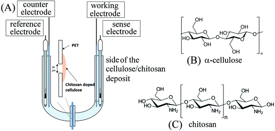 | ||
| Fig. 1 (A) Schematic drawing of the 4-electrode measurement cell. (B) Molecular structure of α-cellulose. (C) Molecular structure of chitosan. | ||
2. Experimental
2.1. Chemical reagents
All reagents such as NaCl (≥98% purity), acetic acid (≥99.8% purity), 1-ethyl-3-methyl-imidazolium acetate ([EMIm][OAc]), dimethyl sulfoxide (DMSO), ethanol (absolute), α-cellulose (C8002, powder), chitosan (75–85% deacetylated) with low molecular weight (26 kDa), medium molecular weight (109 kDa), agarose, and high molecular weight (310–375 kDa) were purchased from Sigma-Aldrich and used without any further purification. All solutions used in the electrochemical studies were prepared in high purity demineralised and filtered water (18.2 MΩ cm resistivity).2.2. Instrumentation
All electrochemical measurements were recorded using an Autolab potentiostat (GPSTAT, Eco Chemie, NL) in a conventional four-electrode configuration (see Fig. 1) and by employing a cell similar to that described in previous ionic diode studies.24 Saturated calomel electrodes (SCE) were used as reference/sense electrodes and platinum wires as counter and working electrodes. FTIR spectra were recorded on a PerkinElmer Frontier FTIR spectrometer in the attenuated total reflection mode between 600 and 4000 cm−1 using 10 scans with a resolution of 1 cm−1. Confocal fluorescence microscopy (ZEISS LSM880) was performed utilising a 405 nm diode laser with a Plan-Apochromat 20×/0.28 M27 objective. An MBS-405 filter was used for the invisible light detector. The maximum distance between slices was 0.5 μm, with a minimum of 46 slices recorded. The cellulose–chitosan film on PET was imaged without modification, placed between a glass slide and a cover-slip to ensure a flat surface.2.3. Procedures for cellulose film and chitosan-doped cellulose film reconstitution
α-Cellulose and [EMIm][AcO] were dried at 80 °C in vacuo overnight, and DMSO was dried over activated 4 Å molecular sieves before use. α-Cellulose (4 wt%) was dissolved in a 30![[thin space (1/6-em)]](https://www.rsc.org/images/entities/char_2009.gif) :
:![[thin space (1/6-em)]](https://www.rsc.org/images/entities/char_2009.gif) 70 wt ratio [EMIm][OAc]
70 wt ratio [EMIm][OAc]![[thin space (1/6-em)]](https://www.rsc.org/images/entities/char_2009.gif) :
:![[thin space (1/6-em)]](https://www.rsc.org/images/entities/char_2009.gif) DMSO solution at 25 °C overnight on a roller table in order to ensure complete dissolution. The concentration of 4 wt% and wt ratio of [EMIm][OAc]
DMSO solution at 25 °C overnight on a roller table in order to ensure complete dissolution. The concentration of 4 wt% and wt ratio of [EMIm][OAc]![[thin space (1/6-em)]](https://www.rsc.org/images/entities/char_2009.gif) :
:![[thin space (1/6-em)]](https://www.rsc.org/images/entities/char_2009.gif) DMSO of 30
DMSO of 30![[thin space (1/6-em)]](https://www.rsc.org/images/entities/char_2009.gif) :
:![[thin space (1/6-em)]](https://www.rsc.org/images/entities/char_2009.gif) 70 were selected to provide optimal viscosity for casting. A 5–10 μL droplet of the cellulose solution was then drop cast onto a 6 μm thick sheet of PET (placed on a 1% agarose gel covered glass slide) with a central laser drilled hole and then distributed with a glass rod to form a thin uniform deposit. PET films with laser-drilled holes were obtained with a range of different diameters: 5 μm, 10 μm, 20 μm, and 40 μm (from Laser-Micro-Machining Ltd, Birmingham, UK). The resulting wet film was rinsed with an anti-solvent to remove the ionic liquid/DMSO. The anti-solvents used were acetic acid 2 wt% solution (in the case of the reconstitution of α-cellulose only) and 2 wt% chitosan in a 2 wt% acetic acid solution (in the case of chitosan-doped cellulose films). Upon contact of the initial film with the anti-solvent a precipitation reaction occurs to give the final cellulose films. The anti-solvent and water rinsed films were dried gently with a flow of warm air and stored under ambient conditions. Typical scanning electron micrographs (SEMs) of films with and without chitosan are shown in Fig. 2. Finally, the PET sheet with the cellulose film was clamped between two flanged J-shaped glass tubes to form a U-shaped cell (see Fig. 1) with the PET sheet and the chitosan doped cellulose membrane partitioning the two chambers as shown. The cellulose film deposit was always oriented facing the working electrode.
70 were selected to provide optimal viscosity for casting. A 5–10 μL droplet of the cellulose solution was then drop cast onto a 6 μm thick sheet of PET (placed on a 1% agarose gel covered glass slide) with a central laser drilled hole and then distributed with a glass rod to form a thin uniform deposit. PET films with laser-drilled holes were obtained with a range of different diameters: 5 μm, 10 μm, 20 μm, and 40 μm (from Laser-Micro-Machining Ltd, Birmingham, UK). The resulting wet film was rinsed with an anti-solvent to remove the ionic liquid/DMSO. The anti-solvents used were acetic acid 2 wt% solution (in the case of the reconstitution of α-cellulose only) and 2 wt% chitosan in a 2 wt% acetic acid solution (in the case of chitosan-doped cellulose films). Upon contact of the initial film with the anti-solvent a precipitation reaction occurs to give the final cellulose films. The anti-solvent and water rinsed films were dried gently with a flow of warm air and stored under ambient conditions. Typical scanning electron micrographs (SEMs) of films with and without chitosan are shown in Fig. 2. Finally, the PET sheet with the cellulose film was clamped between two flanged J-shaped glass tubes to form a U-shaped cell (see Fig. 1) with the PET sheet and the chitosan doped cellulose membrane partitioning the two chambers as shown. The cellulose film deposit was always oriented facing the working electrode.
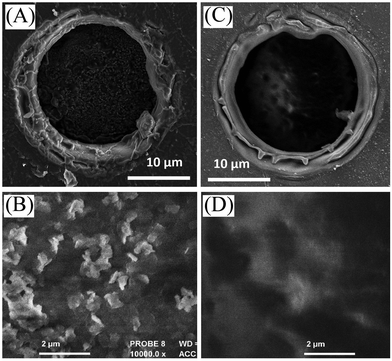 | ||
| Fig. 2 Scanning electron micrograph (SEM) images for (A, B) a cellulose film deposit and (C, D) a chitosan-doped cellulose film deposit on a 20 μm diameter microhole in a PET film. | ||
3. Results and discussion
3.1. Membrane structure based on fluorescence confocal microscopy
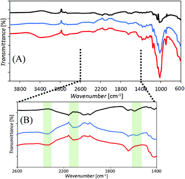
Films of cellulose or chitosan-doped cellulose were deposited asymmetrically onto one side of poly-ethylene-terephthalate (PET) to give ionic diode effects. Fig. 2 shows SEM images of surfaces as viewed from the PET side. Films based on cellulose (A, B) and those based on chitosan-doped cellulose (C, D) exhibit slightly different morphologies, but appear to be well-defined. Chitosan is expected to bind strongly to the cellulose33 and is likely to penetrate throughout the film deposit.Evidence for the presence of a composite material can be obtained from the FTIR data (Fig. 3). Distinct bands (see Fig. 3B) indicative of cellulose and chitosan are detected in the co-deposited material.
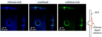
In order to better assess the composition of the chitosan-doped cellulose films and the material distribution in the vicinity of the PET microhole, fluorescence confocal microscopy was performed (Fig. 4). Both cellulose and chitosan auto-fluoresce, exhibiting local emission maxima at 478 nm and 443 nm, respectively,30,34 and are therefore dominant at higher and lower wavelengths, respectively. The separation in emission wavelengths can be utilised to distinguish between the chitosan-rich and the cellulose-rich regions. Hence, fluorescence confocal images were acquired using a UV excitation laser (at 405 nm) and the emission was recorded at 32 channels ranging from 417 to 668 nm. In Fig. 4 the resulting z-stacked images are shown with channels for wavelengths 433 to 477 nm for the chitosan-rich material (blue), channels for wavelengths 513 to 548 for the cellulose-rich material (green), and for all 32 channels overlaid for the combined cellulose and chitosan image (blue and green).
Both blue and green confocal images show a good match in distribution, which suggests that the chitosan-doping process has progressed throughout the entire film (consistent with literature reports30). There was no apparent variation in the distribution of cellulose and chitosan fluorescence when individual channels (corresponding to chitosan and cellulose emission maxima) were overlaid, although there may be slightly less chitosan on the exposed surface of the cellulose (possibly due to washing). It is thus concluded that the chitosan has penetrated relatively uniformly through the entire film. Moreover, it is confirmed that asymmetric film deposition occurs (with a chitosan-doped cellulose film thickness of approximately 5 μm) with the PET microhole only partially filled with the material.
3.2. Chitosan-doping effects on ionic diode characteristics
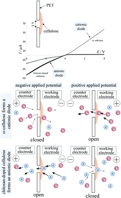
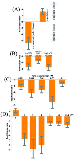
Cyclic voltammograms, performed with a membrane of reconstituted α-cellulose films on a PET film with a 20 μm diameter microhole, exhibit anionic diode behaviour, as shown in Fig. 5 (dotted line) in a 50 mM NaCl solution. The rectification ratios (calculated as the current at +1 V divided by the current at −1 V) are approximately 3–4 (defined here as positive for a “cationic diode” and as negative for an “anionic diode”). Upon the insertion of chitosan into the cellulose film, a switch in diode polarization occurs (see the black line in Fig. 5), leading to the appearance of an anionic diode. The rectification ratio is significantly higher in magnitude compared with that of the diode based on the α-cellulose films only. This improvement in rectification can be attributed to a combination of smaller pore sizes in the film and enhanced overall surface charge, arising from the abundance of amine groups in the chitosan polymer chains.In Fig. 5 a schematic drawing is shown to delineate the cases of a cationic diode (for negatively charged materials resulting in an open state in the positive potential range) and an anionic diode (for positively charged materials resulting in a closed state in the positive potential range). Further mechanisms such as water protolysis under a high potential bias cannot be ruled out, but are assumed here to remain secondary when compared to the ion transfer through the membrane. A bar graph with rectification ratio data comparing α-cellulose and chitosan-doped cellulose is shown in Fig. 6A. The error bars represent an estimated 30% between the prepared batches of cellulose/chitosan films, due to slight variations in film thickness associated with the simple nature of preparation. It can be seen that the chitosan-doped cellulose film allows anion conduction and, as a result, causes an anionic diode effect. The magnitude of rectification is improved when compared with that of the pure reconstituted cellulose film.
3.3. Chitosan-doping effects on diode characteristics: concentration
The effect of chitosan molecular weight on the rectification ratios of the anionic diode was studied with three different molecular weights (low, medium, and high molecular weight chitosan; see Experimental). It was anticipated that the lower molecular weights will show the highest rectification ratios due to the improved penetration into the cellulose films, thus allowing more surface charge to be modified. However, as seen in Fig. 6B, both low and high molecular weights of chitosan yield similar rectification ratios with the medium molecular weight apparently providing the poorest ionic rectifier (tested for 50 mM NaCl). Although, the reasons for the changes in rectification ratio are currently not known in detail, it could be that the self-folding (coiling) of medium and high molecular weight chitosan contributes to a more uneven charge distribution and also affects pore size and charge distribution. The low molecular weight films appear most promising, and therefore all further experiments are performed with low molecular weight chitosan.The influence of NaCl concentration (or ionic strength) on the rectification ratio of the cationic diode was then studied and a summary is shown in Fig. 6C. The rectification ratio increases with ionic strength due to the current in the open state of the membrane being dominated by a decrease in the ionic resistance. However, at even higher ionic strengths (>0.1 M NaCl) a clear decrease in the rectification ratio is observed, which can be attributed to the closed state of the ionic diode becoming ‘leaky’. At high levels of salt the chitosan-doped cellulose film loses the semi-permeability required for the ionic diode effect. In order for the ionic diodes to be used in real applications for desalination of sea water (ca. 0.5 M NaCl), further improvements in rectification ratio and therefore in pore design need to be introduced.
3.4. Chitosan-doping effects on diode characteristics: pH
Next, experiments were performed as a function of solution pH (with aqueous 50 mM NaCl). The aqueous solution pH was adjusted with HCl, or NaOH. Significant effects are seen in Fig. 6D. The solution pH influences the extent of surface protonation of the amine groups along the chitosan backbone.35 An investigation was carried out to study the effects of pH on the rectification ratios of the ionic diode with low molecular weight chitosan-doped cellulose films. The optimal pH value for the ionic diode is approximately 7 (with a positive surface charge from chitosan and with some underlying carboxylate groups providing negative charges to stabilise the composite). Increasing the pH value decreases the amount of protonated amine groups (as well as further increasing negative surface functionalities), which results in films with decreased positive surface charge and hence lower rectification ratios. However, at acidic pH levels, below the pKA of the cellulose carboxylate functional groups, it is evident that the diode reverses its rectification direction and then resembles in characteristics those seen for a simple reconstituted cellulose only diode. This is a permanent change and it also affects the behaviour at other pH values in the following experiments. Therefore, at acidic pH levels chitosan is suggested to be dislodged from the cellulose surface and dissolved into the aqueous solution leaving the cellulose film with a net negative charge. In future, chemical modification (or fixation) and crosslinking between chitosan and cellulose chains may allow the ionic diode to operate over a larger pH range and improve the rectification ratio. However, for realistic applications the neutral pH range is the most relevant.3.5. Chitosan-doping effects on diode characteristics: time constants
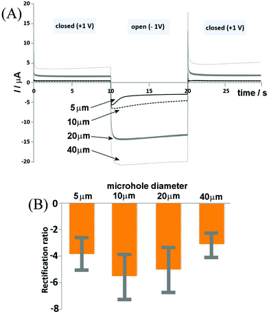
The switching time of the ionic diode is of interest, in order to both understand the possible mechanisms and assess the possibility of utilizing the process for energy conversion and storage. The shorter the switching time, the faster the diode can operate and the smaller the energy losses. Fig. 7 shows chronoamperometry data for switching of a set of chitosan-doped cellulose diodes between the applied potentials of +1 V and −1 V. Data are superimposed for ionic diodes based on PET microholes with: 5, 10, 20, and 40 μm diameters and a clear link between microhole diameter and switching time is observed. The 5 μm diameter microhole appears to have the most rapid response times (slightly over 1 s based on the current decay after the peak signal), whereas larger diodes are somewhat slower. However, for all four types of diodes, a very rapid switching is observed, with most of the transient occurring within the first second. This is consistent with the recently (for Nafion23) proposed model of a diffusion-migration layer responsible for closing the ionic diode.The switching characteristics seem relatively complex (with at least two time constants) and the main current switch is relatively fast (below 1 s) for all ionic diodes. For the potential step to −1 V (diode on transient), a peak feature is seen, followed by a decay. This decay appears fast only for the smallest microhole and is substantially slower for larger microholes. In the open state the diffusion–migration processes result in a re-distribution of charges (ions) within the chitosan-doped cellulose. The fact that differences in the time constant are observed suggests processes involving lateral transport (non-planar; reaching radially into the chitosan-doped cellulose film, or spherically into the aqueous solution phase). More work will be needed to further unravel the mechanism of these processes. A wider range of ionic species (including Ca2+ and Mg2+) as well as other biomaterials need to be tested and the performance of these ionic diodes needs to be improved. However, it has been shown that, similar to α-cellulose providing a cationic diode, chitosan-doped cellulose can be employed as an anionic diode for uni-directional/rectified transport of anions.
4. Conclusion
The versatility in using reconstituted cellulose as a membrane biomaterial for the ionic diode application has been demonstrated by simple modification by means of chitosan-doping. The doping effect appears to occur throughout the cellulose film. The ionic diode is shown to be switchable between cationic and anionic states by “chitosan-doping” and by introducing appropriate surface charges. The application of cellulosic materials in ionic devices could be of considerable interest in particular with further work on nanopore design and microhole geometry.In future, chemical cross-linking between chitosan and cellulose will be required in order to keep the membrane stable over a wider range of pH values (in particular in the more acidic range). Further optimisation of rectification ratio, conductivity, and time response between closed and open states is required for advancing these ionic diode materials into applications, for example in sensing/biosensing. A change in the surface charge could be induced by the binding of a charged analyte (e.g. heavy metals or DNA) and the resulting change in the open/closed diode state would provide a strongly amplified current response.
Conflicts of interest
There are no conflicts of interest.Acknowledgements
B. D. B. A. and F. M. are grateful for support from the Leverhulme Foundation (RPG-2014-308: “New Materials for Ionic Diodes and Ionic Photodiodes”). M. A. J. thanks the EPSRC Doctoral Training Centre in Sustainable Chemical Technologies (EP/G03768X/1) for a stipend. J. L. S, I. P. and M. A. J. acknowledge mobility support from the British Council via the Global Innovation Initiative grant scheme.References
- W. J. Lan, M. A. Edwards, L. Luo, R. T. Perera, X. J. Wu, C. R. Martin and H. S. White, Voltage-rectified current and fluid flow in conical nanopores, Acc. Chem. Res., 2016, 49, 2605–2613 CrossRef CAS PubMed
.
-
H. G. Chun and T. D. Chung, Iontronics, in Ann. Rev. Anal. Chem., ed. R. G. Cooks and J. E. Pemberton, 2015, vol. 8, pp. 441–462 Search PubMed
.
- H. J. Koo and O. D. Velev, Ionic current devices-Recent progress in the merging of electronic, microfluidic, and biomimetic structures, Biomicrofluidics, 2013, 7, 031501 CrossRef PubMed
.
- I. Vlassiouk and Z. Siwy, Nanofluidic diode, Nano Lett., 2007, 7, 552–556 CrossRef CAS PubMed
.
- E. Madrid, P. Cottis, Y. Y. Rong, A. T. Rogers, J. M. Stone, R. Malpass-Evans, M. Carta, N. B. McKeown and F. Marken, Water desalination concept using an ionic rectifier based on a polymer of intrinsic microporosity (PIM), J. Mater. Chem. A, 2015, 3, 15849–15853 CAS
.
- X. Hou, W. Guo and L. Jiang, Biomimetic smart nanopores and nanochannels, Chem. Soc. Rev., 2011, 40, 2385–2401 RSC
.
- Y. Zhang, G. S. Wu, W. Si, J. Ma, Z. S. Yuan, X. Xie, L. Liu, J. J. Sha, D. Y. Li and Y. F. Chen, Ionic current modulation from DNA translocation through nanopores under high ionic strength and concentration gradients, Nanoscale, 2017, 9, 930–939 RSC
.
- W. Guo, Y. Tian and L. Jiang, Asymmetric ion transport through ion-channel- mimetic solid-state nanopores, Acc. Chem. Res., 2013, 46, 2834–2846 CrossRef CAS PubMed
.
- E. Choi, C. Wang, G. T. Chang and J. Park, High current ionic diode using homogeneously charged asymmetric nanochannel network membrane, Nano Lett., 2016, 16, 2189–2197 CrossRef CAS PubMed
.
- Z. Zhang, X. Y. Kong, K. Xiao, Q. Liu, G. H. Xie, P. Li, J. Ma, Y. Tian, L. P. Wen and L. Jiang, Engineered asymmetric heterogeneous membrane: A concentration-gradient-driven energy harvesting device, J. Am. Chem. Soc., 2015, 137, 14765–14772 CrossRef CAS PubMed
.
- G. I. Guerrero-Garcia, F. J. Solis, K. Raidongia, A. R. Koltonow, J. X. Huang and M. O. de la Cruz, Control of selective ion transfer across liquid-liquid interfaces: A rectifying heterojunction based on immiscible electrolytes, ACS Cent. Sci., 2016, 2, 857–866 CrossRef CAS PubMed
.
- Y. Kong, X. Fan, M. H. Zhang, X. Hou, Z. Y. Liu, J. Zhai and L. Jiang, Nanofluidic diode based on branched alumina nanochannels with tunable ionic rectification, ACS Appl. Mater. Interfaces, 2013, 5, 7931–7936 CAS
.
- W. J. Lan, M. A. Edwards, L. Luo, R. T. Perera, X. J. Wu, C. R. Martin and H. S. White, Voltage-rectified current and fluid flow in conical nanopores, Acc. Chem. Res., 2016, 49, 2605–2613 CrossRef CAS PubMed
.
- H. C. Zhang, X. Hou, J. Hou, L. Zeng, Y. Tian, L. Li and L. Jiang, Cone synthetic asymmetric-shaped nanodevices with symmetric pH-gating characteristics, Adv. Funct. Mater., 2015, 25, 1102–1110 CrossRef CAS
.
- E. Madrid, M. A. Buckingham, J. M. Stone, A. T. Rogers, W. J. Gee, A. D. Burrows, P. R. Raithby, V. Celorrio, D. J. Fermin and F. Marken, Ion flow in a zeolitic imidazolate framework results in ionic diode phenomena, Chem. Commun., 2016, 52, 2792–2794 RSC
.
- B. Lovrecek, A. Despic and J. O. M. Bockris, Electrolytic junctions with rectifying properties, J. Phys. Chem., 1959, 63, 750–751 CrossRef CAS
.
- L. Hegedus, N. Kirschner, M. Wittmann and Z. Noszticzius, Electrolyte transistors: Ionic reaction-diffusion systems with amplifying properties, J. Phys. Chem. A, 1998, 102, 6491–6497 CrossRef
.
- K. Zielinska, A. R. Gapeeva, O. L. Orelovich and P. Y. Apel, Diode-like properties of single- and multi-pore asymmetric track membranes, Nucl. Instrum. Methods Phys. Res., Sect. B, 2014, 326, 131–134 CrossRef CAS
.
- Y. Y. Rong, A. Kolodziej, E. Madrid, M. Carta, R. Malpass-Evans, N. B. McKeown and F. Marken, Polymers of intrinsic microporosity in electrochemistry: Anion uptake and transport effects in thin film electrodes and in free-standing ionic diode membranes, J. Electroanal. Chem., 2016, 779, 241–249 CrossRef CAS
.
- N. B. McKeown and P. M. Budd, Exploitation of intrinsic microporosity in polymer-based materials, Macromolecules, 2010, 43, 5163–5176 CrossRef CAS
.
- Y. Y. Rong, Q. L. Song, K. Mathwig, E. Madrid, D. P. He, R. G. Niemann, P. J. Cameron, S. E. C. Dale, S. Bending, M. Carta, R. Malpass-Evans, N. B. McKeown and F. Marken, pH-induced reversal of ionic diode polarity in 300 nm thin membranes based on a polymer of intrinsic microporosity, Electrochem. Commun., 2016, 69, 41–45 CrossRef CAS
.
- E. Madrid, Y. Y. Rong, M. Carta, N. B. McKeown, R. Malpass-Evans, G. A. Attard, T. J. Clarke, S. H. Taylor, Y. T. Long and F. Marken, Metastable ionic diodes derived from an amine-based polymer of intrinsic microporosity, Angew. Chem., Int. Ed., 2014, 53, 10751–10754 CrossRef CAS PubMed
.
- D. He, E. Madrid, B. D. Aaronson, L. Fan, J. Doughty, K. Mathwig, A. M. Bond, N. B. McKeown and F. Marken, A cationic diode based on asymmetric Nafion film deposits, ACS Appl. Mater. Interfaces, 2017, 9, 11272–11278 CAS
.
- B. D. B. Aaronson, D. P. He, E. Madrid, M. A. Johns, J. L. Scott, L. Fan, J. Doughty, M. A. S. Kadowaki, I. Polikarpov, N. B. McKeown and F. Marken, Ionic diodes based on egenerated a-cellulose films deposited asymmetrically onto a microhole, ChemistrySelect, 2017, 2, 871–875 CrossRef CAS
.
- M. A. Johns, A. Bernardes, F. E. G. Guimarães, J. Lowe, E. Ribeiro De Azevedo, E. Gale, I. Polikarpov, J. L. Scott and R. I. Sharma, On the subtle tuneability of cellulose hydrogels: implications for binding of biomolecules demonstrated for CBM 1, J. Mater. Chem. B, 2017, 5, 3879–3887 RSC
.
- E. Gale, R. H. Wirawan, R. L. Silveira, C. S. Pereira, M. A. Johns, M. S. Skaf and J. L. Scott, Directed discovery of greener cosolvents: New cosolvents for use in ionic liquid based organic electrolyte solutions for cellulose dissolution, ACS Sustainable Chem. Eng., 2016, 4, 6200–6207 CrossRef CAS
.
- A. Ostlund, A. Idstrom, C. Olsson, P. T. Larsson and L. Nordstierna, Film modification of crystallinity and pore size distribution in coagulated cellulose films, Cellulose, 2013, 20, 1657–1667 CrossRef
.
- S. Peng, H. Meng, Y. Ouyang and J. Chang, Nanoporous magnetic cellulose– chitosan composite microspheres: preparation, characterization, and application for Cu(II) adsorption, Ind. Eng. Chem. Res., 2014, 53, 2106–2113 CrossRef CAS
.
- S. Alila, S. Boufi, M. Naceur Belgacem and D. Beneventi, Adsorption of a cationic surfactant onto cellulosic fibers I. Surface charge effects, Langmuir, 2005, 21, 8106–8113 CrossRef CAS PubMed
.
- M. A. Johns, Y. H. Bae, F. E. G. Guimarães, E. M. Lanzoni, C. A. Costa, P. Murray, C. Deneke, F. Galembeck, J. L. Scott and R. I. Sharma, 2017, submitted.
- D. W. Lee, C. Lim, J. N. Israelachvili and D. S. Hwang, Strong adhesion and cohesion of chitosan in aqueous solutions, Langmuir, 2013, 29, 14222–14229 CrossRef CAS PubMed
.
- L. Wågberg, G. Decher, M. Norgren, T. Lindström, M. Ankerfors and K. Axnäs, The build-up of polyelectrolyte multilayers of microfibrillated cellulose and cationic polyelectrolytes, Langmuir, 2008, 24, 784–795 CrossRef PubMed
.
- J. Kingkaew, S. Kirdponpattara, N. Sanchavanakit, P. Pavasant and M. Phisalaphong, Effect of molecular weight of chitosan on antimicrobial properties and tissue compatibility of chitosan-impregnated bacterial cellulose films, Biotechnol. Bioprocess Eng., 2014, 19, 534–544 CrossRef CAS
.
- C. Pöhlker, J. A. Huffman and U. Pöschl, Autofluorescence of atmospheric bioaerosols - fluorescent biomolecules and potential interferences, Atmos. Meas. Tech., 2012, 5, 37–71 Search PubMed
.
- Q. Z. Wang, X. G. Chen, N. Liu, S. X. Wang, C. S. Liu, X. H. Meng and C. G. Liu, Protonation constants of chitosan with different molecular weight and degree of deacetylation, Carbohydr. Polym., 2006, 65, 194–201 CrossRef CAS
.
| This journal is © The Royal Society of Chemistry 2017 |

