Recent progress in the direct synthesis of hierarchical zeolites: synthetic strategies and characterization methods
Zhaohui
Liu
 a,
Yingjie
Hua
b,
Jianjian
Wang
 a,
Xinglong
Dong
 a,
Qiwei
Tian
 c and
Yu
Han
 *ad
*ad
aAdvanced Membranes and Porous Materials Center, Physical Sciences and Engineering Division, King Abdullah University of Science and Technology, Thuwal 23955-6900, Saudi Arabia. E-mail: yu.han@kaust.edu.sa
bHainan Normal University, School of Chemistry and Chemical Engineering, Haikou, China
cThe Key Laboratory of Resource Chemistry of Ministry of Education, Shanghai Key Laboratory of Rare Earth Functional Materials, and Shanghai Municipal Education Committee Key Laboratory of MolecularImaging Probes and Sensors, Shanghai Normal University, Shanghai 200234, China
dKAUST Catalysis Center, Physical Sciences and Engineering Division, King Abdullah University of Science and Technology, Thuwal 23955-6900, Saudi Arabia
First published on 16th June 2017
Abstract
Hierarchically structured zeolites combine the merits of microporous zeolites and mesoporous materials to offer enhanced molecular diffusion and mass transfer without compromising the inherent catalytic activities and selectivity of zeolites. This short review gives an introduction to the synthesis strategies for hierarchically structured zeolites with emphasis on the latest progress in the route of ‘direct synthesis’ using various templates. Several characterization methods that allow us to evaluate the ‘quality’ of complex porous structures are also introduced. At the end of this review, an outlook is given to discuss some critical issues and challenges regarding the development of novel hierarchically structured zeolites as well as their applications.
1. Introduction
As widely used catalysts and sorbents, zeolites are a class of crystalline microporous inorganic materials (silicates, aluminosilicates, titanosilicates, aluminophosphates, etc.) with ordered cavities and channels of molecular dimensions (0.3–1 nm). The uniform microporous structures of zeolites offer a “molecular sieve” function, accounting for their unique size- and shape-selectivity in adsorption, separation, and catalysis applications.1–7 On the other hand, however, the small pore sizes impose restriction on molecular diffusion and mass transport within zeolite crystals and prohibit large molecules from accessing the intra-crystalline active sites.3,8–10 Consequently, adsorption processes and catalytic reactions based on zeolites are often limited by slow diffusion, and zeolites are incapable of catalyzing reactions involving large molecules.8–10Ordered mesoporous silicas (OMSs), which are synthesized through a supramolecular self-assembly route by using surfactant molecules as templates, constitute another class of materials with regular porous structures.11–14 Different from microporous zeolites, OMSs possess much larger and tunable pores that reside in the range of “mesopores” (2–50 nm). Since the first report of OMSs in 1992,11 significant efforts have been made to explore their potential as catalysts for large molecule reactions, but unfortunately their amorphous nature results in low catalytic activity and weak hydrothermal stability, making them not as useful as zeolites.12–15
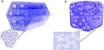
It is natural to think that integrating mesopores and zeolitic micropores in one single material (namely, fabricating hierarchically structured zeolites) may provide a solution to the problems associated with zeolites and OMSs alone. An ideal material is schematically illustrated in Fig. 1, which has ordered mesoporous channels encompassed by zeolitic structures.16 Such a material can be considered as a zeolite with intra-crystalline mesopores, or alternatively, as a mesoporous material with crystalline zeolitic walls, in which the mesopores allow fast diffusion and enhanced accessibility for bulky molecules, while the zeolitic structure can provide catalytic activity and selectivity.16–18 From the perspective of material synthesis, it is extremely difficult, if not impossible, to synthesize a material with ordered pores at both atomic and mesoscopic scales as shown in Fig. 1, because it requires the crystalline wall to be highly curved and strained. Note that for most practical applications, whether the material has ordered mesopores (mesoscopic structural ordering) is not crucial, but instead it is the size, concentration, and connectivity of mesopores in zeolite crystals that determine the molecular diffusion and catalytic properties.19,20 Therefore, it is a fundamental challenge but not a practical concern to generate ordered mesopores in zeolites. In fact, the large majority of hierarchically structured zeolites (simply referred to as “hierarchical zeolites” hereafter) reported in the literature have either lamellar (without curved pore walls)17,21,22 or disordered mesostructures.23–25
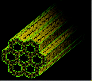 | ||
| Fig. 1 Schematic illustration of an ideal hierarchically structured zeolite that has ordered mesoporous channels encompassed by microporous zeolitic walls (courtesy of Dr Ryoo Ryong). | ||
The direct effects of introducing mesopores in zeolites are (i) the increase of accessible surface area to bulky molecules and (ii) the reduction of intra-crystalline diffusion length.26–28 Although these two effects can in principle be realized by synthesizing ultra-fine zeolite crystals, it is difficult in practice to synthesize zeolites with sub 100 nm crystal sizes, and even if the synthesis is successful, such small particles are difficult to handle in practical applications.29–31 In contrast, the incorporation of mesopores into zeolite crystals can significantly reduce the intra-crystalline diffusion length down to as short as a few nanometers while maintaining the large particle sizes.32–34 In the context of catalysis, as compared to conventional bulk zeolites, hierarchical zeolites usually show higher activities for bulky reactants,8,35 modulated selectivity,36,37 and reduced coke formation and thus longer catalyst lifetime.38–40 All of these properties are associated with the increased accessibility to the active sites, promoted molecular transport, and shortened intra-crystalline contact time. Likewise, hierarchical zeolites exhibit enhanced adsorption kinetics compared to conventional zeolites when used as adsorbents or separation media.41–44
In the last decade, significant efforts have been devoted to the preparation of hierarchical zeolites, which has spawned a vast amount of literature including many nicely written review papers.1,10,27,45–49 Post-treatment methods, such as steaming, acid (or base) leaching, and chemical treatment, have been used to create mesopores in zeolites.33,50–57 These processes are eco-unfriendly and only produce poorly defined mesopores. By comparison, direct synthesis of hierarchical zeolites through a “templating route” allows more precise control of the mesoporosity and also better integrity of the zeolite structures by avoiding desilication or dealumination. In this review, we will focus on various templating routes, giving special attention to the most recently developed synthetic strategies (e.g., polymer-based two-in-one templates) that were not covered in previous reviews. Meanwhile, we will discuss how to evaluate the “quality” of the produced hierarchically porous structure by different characterization methods including electron microscopy tomography, gas adsorption/desorption, positron annihilation, and kinetic uptake of probe molecules.
2. Synthetic strategies for hierarchical zeolites
2.1 Hard-templating route
Carbon materials are often used as hard templates for synthesizing hierarchical zeolites, simply because they can be easily burned out after the synthesis to generate mesoporosity.58–63 There are two typical scenarios for this route: (i) small amorphous carbon particles, e.g. carbon blacks particles with a size of tens of nanometers, are dispersed in the synthetic gel of a zeolite. During the crystallization of the zeolite, the carbon particles are incorporated into the crystals, which produce mesoporosity upon calcination (Fig. 2a).59 The success of this strategy seems limited to MFI zeolites (Fig. 2b), possibly because other zeolites do not have sufficient tolerance to involve “impurity” during their crystallization.58–61,64 (ii) As opposed to the first scenario described above where the zeolite is the major phase with the carbon template randomly dispersed inside, the other strategy is to confine the growth of a zeolite within the void spaces in porous carbon (the carbon material constitutes a continuous phase) (Fig. 2c).62 Similarly, the carbon template can be removed by calcination afterwards to generate porosity between the zeolite crystals. The porous carbon templates can be prepared by another templating-synthesis procedure from the assemblies of silica particles or surfactant micelles.63 This confined-space synthetic strategy proves to be generally applicable to different kinds of zeolites (MFI, BEA, LTA, FAU and LTL) (two examples are shown in Fig. 2d).58–60,62 Interestingly, despite the presence of mesoporosity, hierarchical zeolite MFI synthesized with carbon black shows single-crystalline nature, as evidenced by the electron diffraction patterns (Fig. 2).59 Fan et al.62 found similar phenomena when they synthesized hierarchical zeolites (MFI, BEA, LTA and FAU) in the confined space within three-dimensionally ordered mesoporous (3DOm) carbon, whereas an exception is the case of hierarchical zeolite LTL prepared by the same procedure, which is polycrystalline. The authors attributed this difference to the relative magnitude of nucleation and crystal growth rates: large single crystals are grown through many interconnecting mesopores of 3DOm when crystal growth is dominant, while randomly-oriented nanocrystals are formed when abundant nucleation occurs in the initial synthesis cycle and crystal growth is relatively slow.62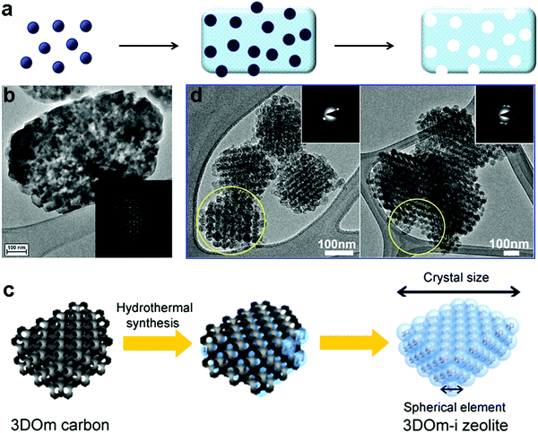 | ||
| Fig. 2 (a) Schematic illustration of “hard-templating” synthesis of hierarchical zeolites using carbon nanoparticles. (b) TEM image of a hierarchical zeolite ZSM-5 crystal synthesized from the route illustrated in (a).59 (c) Schematic illustration of “hard-templating” synthesis of hierarchical zeolites using the confined spaces of porous materials.62 (d) TEM images of hierarchical zeolite LTA (left) and BEA (right).62 Reprinted with permission from ref. 60 and 63. Copyright 2000 and 2011, American Chemical Society. | ||
In addition to carbon materials, CaCO3,65 silica66 and polystyrene (PS) spheres67 have also been used as hard templates to prepare hierarchical zeolites. In general, the hard-templating route usually only gives rise to limited mesoporosity and the low yield of the hierarchical zeolite is another issue associated with this method.
2.2 Synthesis using mixed templates
In comparison with the hard-templating route, “soft-templating” is a more generalized method that uses large organic molecules as the mesopore template to achieve better control of the mesopore size and pore connectivity.68 Initial attempts of the soft-templating route were based on the use of a mixed template of surfactant molecules and small cations that act as the structure-directing agent (SDA) of the zeolite, with the aim of simultaneously forming mesoporous and microporous zeolitic structures in one material. The idea of using surfactants as templates for the mesoporous structure is inherited from the systems of mesoporous silicas in which the self-assembly ability of the surfactant is utilized to direct the formation of ordered mesostructures.11 However, it turned out that in most cases, simply mixing the two types of templates only gave a mixture of zeolite crystals with an amorphous mesoporous silica as a result of phase separation, due to the competition between the two different templating systems. To overcome this problem, Ryoo et al.69 designed a unique surfactant that features a silane-containing head group to enhance its interaction with the growing zeolite crystals during the self-assembly process. In this way, they successfully prepared mesoporous MFI and LTA zeolites (Fig. 3). Independently, Pinnavaia et al.70 reported a similar strategy, using a silane-functionalized polymer to form intracrystal mesopores in zeolite ZSM-5 (MFI). A common idea behind these studies, in which two kinds of templates are still required, was that a silane-functionalized template could provide a “bridge” between mesopores and the zeolite framework to avoid phase separation. The same strategy (i.e., using an organosilane surfactant as a co-template) has also been applied by Yu et al.39 to synthesize hierarchical SAPO-34.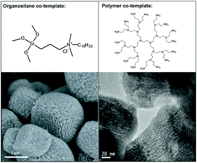 | ||
| Fig. 3 Typical examples of hierarchical zeolites synthesized using mixed templates: (left) SEM image of hierarchical zeolite LTA;18 (right) TEM image of hierarchical zeolite SAPO-34.72 The corresponding co-templates that are used to generate mesoporosity are shown on top of the images. Reprinted with permission from ref. 18 (Copyright 2006, Nature publishing group) and ref. 73 (Copyright 2014, Royal Society of Chemistry). | ||
Xiao et al.71 reported the use of a polymer, polydiallyldimethylammonium chloride (PDADMA), combined with tetraethylammonium (TEAOH), which is the conventional SDA for zeolite BEA to synthesize hierarchical zeolite Beta. Interestingly, it was found several years later by the same group that PDADMA alone can act as a dual-function template to generate mesopores in zeolite Beta (refer to the section on ‘polymer-based dual-function templates’ for more discussions).24 Therefore, the earlier system is likely a single-template rather than a mixed-template system, namely, it is the polymer PDADMA instead of the mixture of PDADMA and TEAOH that is responsible for the hierarchical structure. In addition, hierarchical SAPO-34 was synthesized by using polyethyleneimine (PEI) dendrimer and triethylamine (TEA) to direct the formation of mesopores and micropores respectively.72 We notice that the successful examples of the mixed-template route (without phase separation) involve the use of either organosilane surfactant18,69,70,72–78 or non-surfactant polymers71,79–82 as the co-template. This is possibly because the former maximizes the interaction between the co-template and the zeolite framework, while the latter minimizes the interaction between the co-template molecules. Both of these two effects help to avoid phase separation. In contrast, using conventional surfactants as co-templates always results in separation between the mesostructure and the zeolitic structure due to their strong self-assembly tendency. This point will be further discussed in the section on ‘polymer-based dual-function templates’.
2.3 Surfactant-based dual-function templates
It is reasonable to expect that the most effective way to avoid phase separation would be the use of a two-in-one template, which has dual structure-directing abilities in two different length scales. To this end, Ryoo's group developed a new class of surfactants, which feature hydrophilic multi-ammonium head groups covalently linked to long hydrophobic hydrocarbon tails (Fig. 4a).83–93 In these new surfactants, the head groups have similar structures to conventional zeolite SDAs (quaternary ammoniums) and can thus act as SDAs for zeolite structures, while at the same time their long tails can generate mesostructures by self-assembly, just like conventional surfactants do for the synthesis of mesoporous silica materials. With this strategy, the zeolite SDA functionality and mesostructure templating functionality are covalently connected in one surfactant molecule that can act as a dual-function (two-in-one) template to fabricate hierarchical zeolites without the need for using separate zeolite SDAs (small cations).83–93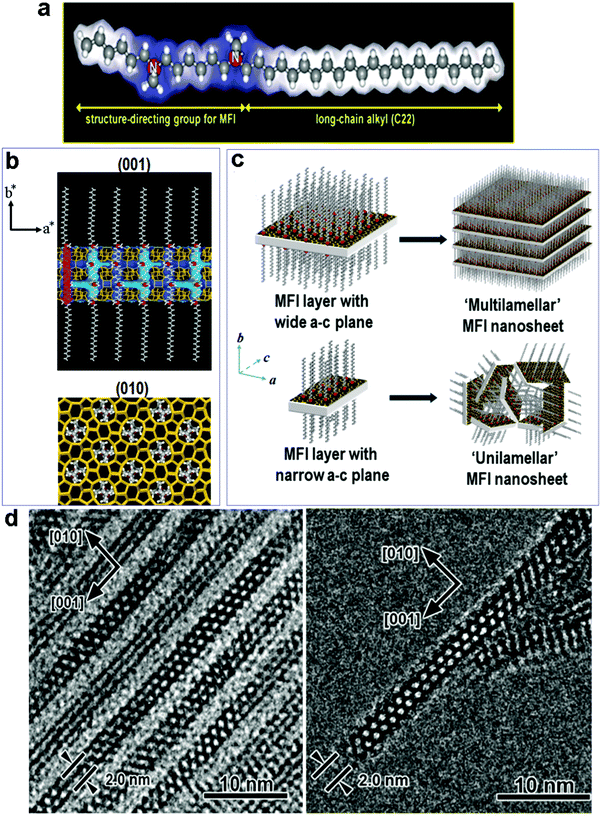 | ||
| Fig. 4 (a) The dual-function surfactant template used for the fabrication of zeolite MFI nanosheets, in which the head group can act as a SDA for the formation of the zeolite structure. (b) Proposed structure model for the single MFI nanosheet. Surfactant molecules are aligned along the straight channel of the MFI framework. Two quaternary ammonium groups (indicated as red spheres) are located at the channel intersections; one is inside the framework, and the other is at the pore mouth of the external surface. (c) Assembly of MFI nanosheets in the form of either multilamellar stacking along the b-axis, or in a random way of unilamellar structure. (d) (left) TEM image of multilamellar MFI nanosheets, revealing alternating layers of zeolite and surfactant micelles. TEM image of a unilamellar MFI nanosheet.83 Reprinted with permission from ref. 84. Copyright 2009, Nature Publishing Group. | ||
On the basis of this creative idea, Ryoo's group synthesized a series of hierarchical zeolites by varying the SDA groups on the surfactant templates.83–93 Their work well demonstrates the feasibility of directing a zeolite structure with local functional groups of a large molecule. The most representative example was reported in 2009 (Fig. 4),83 in which a specially designed surfactant, C22H45–N+(CH3)2–C6H12–N+(CH3)2–C6H13 (Fig. 4a), was used as a dual-function template to fabricate hierarchical MFI zeolites. The surfactant molecules assemble into lamellar micelles, while two-dimensional (2-D) zeolite MFI sheets are formed between the micelle layers as directed by the –N+(CH3)2–C6H12–N+(CH3)2–C6H13 head groups (Fig. 4b). As such, alternating organic and zeolite layers are generated through one-pot synthesis. Interestingly, the zeolite layer grown in the a–c plane is as thin as 2 nm in the b-axis direction, corresponding to one single unit cell thickness (Fig. 4b). By controlling the dimension of the MFI sheet in the a–c plane, the sheets can form a multi-lamellar or uni-lamellar configuration (Fig. 4c), and the latter gives rise to higher mesoporosity upon the removal of the organic template by calcination. The same group later reported that the thickness of the MFI sheets can be precisely tuned by modifying the head group of the surfactant, with a direct correlation between the number of ammonium groups in the surfactant and the thickness of the MFI sheets.85
Fig. 5a shows some examples of the dual-function surfactant templates that have been used to fabricate hierarchical zeolites with different framework types.83–93 Besides the well-defined lamellar mesostructure achieved for the case of zeolite MFI, disordered (random sponge-like) mesoporous structures were obtained for other framework types of zeolite including BEA, MTW, MRE, and ATO.88,91 In these cases, the materials are essentially composed of ultra-small (<10 nm) zeolite crystals that are agglomerated with random orientations, in which mesoporosity is generated by disordered surfactant micelles among the agglomerated crystals (Fig. 5b and c). These results suggest that it is difficult to achieve 3-D (non-lamellar) long-range structural ordering at the mesoscale and atomic scale simultaneously in hierarchical zeolites, as illustrated in Fig. 1. This is because, as discussed earlier, a 3-D non-lamellar mesoporous structure requires the zeolitic wall to be curved, which would produce significant strain and is therefore unfavorable. The first and thus far only hierarchical zeolite with an ordered, non-lamellar mesostructure was also reported by Ryoo's group in 2011.85 In this work, the use of the surfactant C18H37–N+(CH3)2–C6H12–N+(CH3)2–C6H12–N+(CH3)2–C18H37 led to the formation of hexagonally ordered mesoporous channels and crystallinity was observed on the pore walls. However, this material only possesses short-range ordering of the zeolite structure in this material, as revealed by few broad peaks in the X-ray diffraction pattern and intermittent lattice fringes in the HRTEM image (Fig. 5d and e). The very short-range ordering makes it impossible to assign the zeolitic structure with a framework type. This result is also a testament to the existence of a trade-off between the zeolitic framework and mesoporous structure in the degree of their structure ordering.85
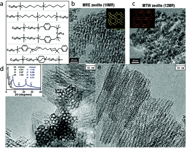 | ||
| Fig. 5 (a) Some dual-function surfactant-based templates that have been used to fabricate hierarchical zeolites. TEM images of (b) hierarchical zeolite MRE and (c) hierarchical zeolite MTW.91 HRTEM images of a hierarchical zeolite with hexagonally ordered mesoporous channels acquired (d) along and (e) perpendicular to the channels.85 The inset of (d) is the XRD pattern of this material, in which the low-angle reflections indicate the ordering of the mesostructures while the high-angle broad reflections suggest the presence of zeolite-like structures in the pore wall. Reprinted with permission from ref. 92 (Copyright 2014, American Chemical Society) and ref. 86 (Copyright 2011, American Association for the Advancement of Science). | ||
It was believed that multiple quaternary ammonium groups in the surfactant template are required to direct the formation of the zeolite structure. However, a recent study by Che et al.21,22,94 showed that a single quaternary ammonium head surfactant can also act as a dual-function template to form mesostructured zeolite MFI nanosheets. The key to success is the incorporation of aromatic (biphenyl and naphthyl) groups into the surfactant molecules to induce strong self-assembly through π–π stacking so as to stabilize the structure.21 The obtained structure is microscopically similar to the multilamellar MFI nanosheets shown in Fig. 4, but macroscopically different, because it involves the 90° rotational intergrowth of MFI nanosheets, leading to a 3-D interconnected “house-of-cards-like” network. A similar hierarchical structure, which is also based on zeolite MFI, had been synthesized through a template-free process by Tsapatsis's group (refer to the section on ‘template-free synthesis’).32,95
2.4 Polymer-based dual-function templates
Initial attempts of two-in-one (dual-function) templates were exclusively based on surfactants. This is likely driven by the long-pursued objective of preparing ordered mesoporous materials with crystalline zeolitic walls (Fig. 1), given the special ability of surfactants to form ordered mesostructures through supermolecular self-assembly. Although the strategy of using dual-function templates instead of mixed templates successfully eliminates the phase separation problem, there still remain two major processes in the synthetic system, i.e., (i) the condensation of aluminosilicates to form a zeolitic framework and (ii) the assembly of surfactant molecules to form the mesostructure. These two processes are, both thermodynamically and kinetically, incompatible with each other: the presence of non-lamellar mesoporous structures (channels and/or cages) in a zeolite crystal would induce severe strains that are accumulated with the density of mesopores; a mesostructure can be formed in minutes, while crystallization of zeolites usually takes several days. Consequently, it is very difficult, if not impossible, to achieve long-range order for both zeolitic and mesoporous structures simultaneously even using a dual-function template. As discussed in previous sections, for example, with a surfactant-based dual-function template, it is possible to get ordered mesostructures, being lamellar or hexagonal, while there are no three-dimensionally long-range ordered zeolite structures but only 2-D zeolite sheets or tiny zeolite grains with sub-unit cell dimensions obtained at the same time.16,17,21Given the inherent trade-off between the zeolitic framework and the mesoporous structure in structure ordering, two opposing scenarios can be expected. The first has been discussed above, where the self-assembly ability of the surfactant template favors the formation of an ordered mesostructure at the expense of losing the long-range structural ordering in the zeolitic framework (Fig. 6a). The other is that large zeolite single crystals containing disordered mesopores can be made (Fig. 6b), if the interaction between the template molecules is minimized, for example, by using non-surfactant macromolecules as a template.24 In the latter case, the macromolecules are not a ‘template’ in a traditional sense, because they don't have the function of directing the formation of a well-defined mesostructure, but instead they simply act as a ‘porogen’ to generate mesoporosity. In the context that mesoporous zeolites are potential heterogeneous catalysts for oil conversion and refinery, where the ordering of the mesostructure is inessential but the stability of the catalyst is a crucial criterion, the second scenario may be more desirable because better structural integrity at the atomic scale would bring greater stability to the material.
Based on these considerations, Xiao and Han et al.24 first proposed that non-surfactant polymers containing quaternary ammonium groups can be used to prepare mesoporous zeolite single crystals. To verify this hypothesis, they used a commercial cationic polymer, polydiallyldimethylammonium chloride (PDADMA) (Fig. 7a) for the synthesis of hierarchical zeolite Beta (BEA framework type). The obtained material (denoted as Beta-MS) consists of relatively uniform particles (700–800 nm) with remarkable mesoporosity, as revealed by the SEM image (Fig. 7b), which is further confirmed by the Ar adsorption isotherms (Fig. 7d). In comparison with the conventional bulk zeolite Beta, Beta-MS has more than three times higher total pore volume (up to ∼0.9 cm3 g−1).24 Disordered mesopores and periodically arranged zeolitic 12-ring channels can be simultaneously observed in the HRTEM images (Fig. 7c). The presence of intra-crystalline mesopores breaks the zeolite framework into small yet continuous domains, and the thinnest domain is ∼3 nm in diameter, containing only two 12-ring channel layers (Fig. 7c).24 This result indicates that a polymer-based template can produce hierarchical zeolites with diffusion length as short as that of 2-D zeolite nanosheets from the surfactant-based template.16 Interestingly, despite the existence of a large number of mesopores, each particle proved to be a single crystal, as evidenced by electron diffraction, electron diffraction tomography, and high-resolution TEM (Fig. 7c). The single crystalline nature of Beta-MS has been attributed to the use of a non-surfactant polymer template for the synthesis. The abundant quaternary ammonium groups on the polymer play the role of SDA for the zeolite, which is similar to the cases of surfactant-based dual-function templates. Unlike surfactants, however, PDADMA molecules do not self-assemble to form regular micelles or ordered structures due to the absence of hydrophobic segments, but instead they are incorporated into zeolite crystals in a random manner to give rise to disordered mesopores. As such, the crystallization of the zeolite is not disturbed by the self-assembly of the template, while the high flexibility of PDADMA molecules allows the zeolite to crystallize into a thermodynamically more stable form, i.e., into a single crystal. Simply, because non-surfactant polymers impose little interference to the crystallization of zeolites, they favor the formation of 3-D continuous zeolite frameworks with a long-range order (single crystals), which are different from the 2-D zeolite nanosheets or agglomeration of randomly-oriented zeolite grains obtained from the surfactant templates.24
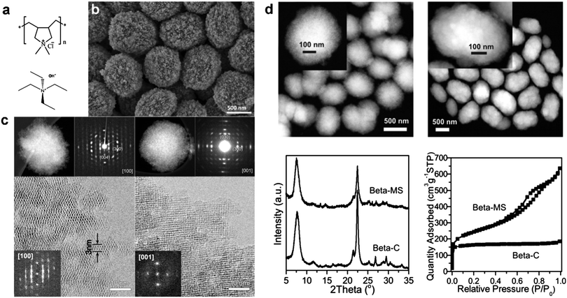 | ||
| Fig. 7 (a) Dual-function polymer template (PDADMA) used for the synthesis of hierarchical zeolite Beta (Beta-MS), in comparison with conventional small-molecule SDA (TEAOH) used for the synthesis of bulk zeolite Beta (Beta-C). (b) SEM image of Beta-MS. (c) STEM images, selected-area ED patterns, and HRTEM images of Beta-MS acquired along the [100] and [001] zone axes.24 (d) STEM image, XRD pattern, and Ar sorption isotherm of Beta-MS in comparison with those of Beta-C.37 Reprinted with permission from ref. 24 (Copyright 2014, American Chemical Society) and ref. 37 (Copyright 2015, American Chemical Society). | ||
A tomography technique based on scanning transmission electron microscopy (STEM) revealed that Beta-MS possesses a disordered yet three-dimensionally interconnected mesoporous system with crystals. The diameter of the mesopores can be tuned in the range of 4 nm to 10 nm by simply varying the molecular weight of PDADMA from 50 K to 500 K.24 Thanks to its single crystalline nature, Beta-MS shows excellent stability under hydrothermal conditions, with negligible structural degradation after being exposed to 100% steam flow at 973 K for 2 h.24 Beta-MS also exhibits higher catalytic activities in reactions involving large molecules, such as the alkylation of benzene with benzyl alcohol and the condensation of benzaldehyde with hydroxyacetophenone, as compared to bulk zeolite Beta with the same Si/Al ratio.24 It was later demonstrated that Beta-MS is a superior catalyst for the conversion of methanol to hydrocarbons, exhibiting a 2.7-fold larger conversion capacity, a 2.0-fold faster reaction rate, and a remarkably longer lifetime than conventional zeolite Beta.37
Han's group further developed the polymer-based dual-function templating strategy.25 They first demonstrated that this strategy can be generalized by using polymers grafted with different SDA groups to fabricate hierarchical zeolites. Specifically, they designed two cationic non-surfactant polymers, poly(N1,N1-diallyl-N1-methyl-N6,N6,N6-tripropylhexane-1,6-diamonium bromide) (PDAMAB-TPHAB) and poly(N1,N1-diallyl-N1-methyl-N6,N6,N6-trimethylhexane-1,6-diamonium bromide) (PDAMAB-TMHAB) (see Fig. 8a), to synthesize MFI- and BEA-type hierarchical zeolites, respectively. The obtained materials also exhibit single crystalline or approximate single-crystal (each particle is composed of a few single crystals) properties, corroborating their hypothesis proposed in the previous work of Beta-MS.24 With PDAMAB-TPHAB, hierarchical zeolite MFI materials with different compositions have been synthesized, including silicate (Silicalite-I), aluminosilicate (ZSM-5), and titanosilicate (TS-1), and this synthetic system shows a large tolerance for variation in composition (Si/Al: ∞ – 30; Si/Ti: ∞ – 60). All these materials have smaller crystal domains as evidenced by the broadened XRD peaks and much higher pore volumes (due to the remarkable mesoporosity), as compared to the bulk zeolite MFI (Fig. 8b and c). The hierarchical MFI materials show an interesting “fibrous” structure, having ultra-thin “fibers” around the particle periphery protruding along the c-axis direction, of which the thinnest region is about 3.5 nm, containing only three 10-ring channel layers (Fig. 8d). The “fibers” have been proven not to be lateral projections of 2D nanosheets by electron tomography but a unique one-dimensional (1-D) structural feature (see the next section for more discussion). The hierarchical ZSM-5 exhibits superior catalytic properties for reactions that easily produce cokes (conversion of methanol to aromatics) or involve large molecules (cracking of canola oil to produce light olefins).25
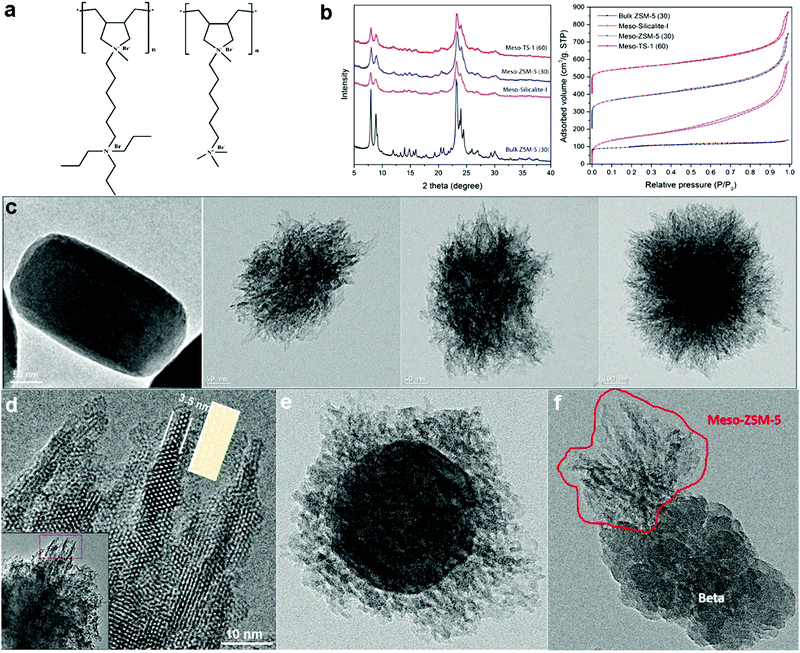 | ||
| Fig. 8 (a) Non-surfactant polymers used for the synthesis of MFI- and BEA-type hierarchical zeolites. (b) XRD patterns and N2 sorption isotherms of MFI-type hierarchical zeolites (meso-Silicalite-I, meso-ZSM-5 and meso-TS-1), in comparison with those of bulk MFI-type zeolite (ZSM-5). (c) TEM images of bulk ZSM-5, meso-TS-1, meso-ZSM-5 and meso-Silicalite-1 (from left to right). (d) HRTEM of image taken along the [010] direction at the periphery of a meso-ZSM-5 particle, showing the fibrous structure. The structure model of the MFI-type framework projected along [010] direction is placed beside a “fiber” for comparison. The inset at the left lower corner is a low-magnification TEM image highlighting where the HRTEM image was acquired. (e) TEM image of a core–shell structured ZSM-5@meso-ZSM-5 material, which has bulk ZSM-5 crystals as the core and hierarchical ZSM-5 as the shell. (f) TEM image of a “dimer” structure, formed by the intergrowth of mesoporous ZSM-5 on a bulk zeolite Beta crystal.25 Reprinted with permission from ref. 25. Copyright 2016, Wiley-VCH. | ||
In the same report, the authors demonstrated extra merits of using polymer-based templates to synthesize hierarchical zeolites, in addition to the generation of a 3-D mesoporous system and a single-crystalline zeolite framework.25
First, polymer chains can easily be grafted with functional groups. Thus, different functionalities (e.g., adsorption capacity, catalytic activity, molecular recognition ability, and/or fluorescence) can be “carried” into hierarchical zeolites to produce multifunctional materials by modifying the polymer template with the corresponding functional groups. To prove this concept, they simply utilized the redundant quaternary ammonium groups in PDAMAB-TPHAB to adsorb tetrachloroplatinate(II) anions ([PtCl4]2−), achieving a high loading (∼2.5 wt%) of ultrafine Pt nanoparticles (1–2 nm) uniformly dispersed in hierarchical ZSM-5. By conventional wet impregnation methods, it is difficult to prepare such small, well-dispersed Pt nanocrystals on a zeolite support at such a high level of loading.25
Second, and more interestingly, unlike conventional SDAs of zeolites that are free cations in solution, polymer-based templates can anchor to an existing surface to induce heterogeneous nucleation of zeolites therein. Taking this advantage, it is in principle possible to fabricate a continuous mesoporous zeolite layer on the surfaces of various materials, provided that a material can survive in the hydrothermal conditions used for the zeolite synthesis. This idea has been validated by the successful synthesis of unprecedented core–shell-structured hierarchical zeolites, including ZSM-5@meso-ZSM-5 and Beta@meso-Beta, through seeded-growth, in which a mesoporous zeolite shell is homogeneously coated on the surface of pre-synthesized bulk zeolite crystals in the presence of a polymer template (Fig. 8e). Different from the amorphous silica shells in common silica-coated nanocrystals, the zeolitic shell fabricated by this means is porous and crystalline with greater functionalities. However, it is worth noting that the results of this initial study also implied that epitaxial growth (i.e., lattice matching between the core and the shell) is a prerequisite for the formation of a core–shell structure, namely, the core and the shell need to have the same zeolite structure. When zeolite Beta crystals were used as seeds to grow meso-ZSM-5, meso-ZSM-5 grew only from the defective sites of the seed crystal, forming a “dimer” structure (Fig. 8f). This result suggests that it is inorganic aluminosilicates rather than polymer molecules that first deposit on the seed surface, otherwise lattice matching would not be necessary for continuous shell growth. The feasibility of coating hierarchical zeolites on an arbitrary surface needs to be further explored, probably by modifying the polymer with groups that have specific interactions with the targeted surface.
Ryoo's group independently reported the use of polymers as dual-function templates to synthesize hierarchical zeolites with disordered (sponge-like) mesopores.23 Different from the polymers discussed above, their polymers are linear polystyrenes randomly grafted with multi-ammonium SDA groups, containing both hydrophilic and hydrophobic segments. These polymers have two advantages: (i) the obtained mesopores are more uniform, and (ii) the mesoporosity can be adjusted by varying the percentage of the hydrophobic segments. On the other hand, however, the presence of hydrophobic segments in the polymer may induce interaction between template molecules, like the cases of surfactant-based templates, giving rise to polycrystalline instead of single-crystalline products.
2.5 Template-free self-pillared hierarchical zeolites
Interestingly, it is possible to directly synthesize a hierarchical zeolite without using any template for the formation of mesopores. Tsapatsis et al. wisely utilized the 90° rotational intergrowths of a zeolite to fabricate a “house-of-cards-like” network of self-pillared zeolite MFI nanosheets with mesoporosity formed among the nanosheets (Fig. 9).32 The formation of such a unique morphology is attributed to the orthogonal intergrowth of MFI (MFI twins) that is induced by higher-symmetry framework type MEL segments at twin boundaries (Fig. 9). This rotational intergrowth strategy has been applied to fabricate hierarchical FAU/EMT zeolites.96 This template-free method is facile and effective, but it is limited to very few types of zeolite frameworks that have a strong tendency towards repetitive rotational intergrowth. | ||
| Fig. 9 (a) Schematic illustration of the formation of template-free self-pillared hierarchical zeolites by rotational intergrowth.95 (b) TEM image of self-pillared zeolite MFI.32 Reprinted with permission from ref. 96 (Copyright 2014, Wiley-VCH) and ref. 32 (Copyright 2012, American Association for the Advancement of Science). | ||
3. Characterization methods for hierarchical zeolites
Conventional characterization methods used to probe the structures and properties of zeolites, such as diffractions, electron microscopic imaging, physical and chemical sorption, various types of spectroscopy, etc., can all be used to characterize hierarchical zeolites. However, in addition to the inherent properties from the crystalline zeolitic structure, the mesoporosity of hierarchical zeolites is closely related to their applications, where the pore density, pore sizes, and pore connectivity are crucial properties that would determine the mass transfer and active site accessibility within the materials. However, the characterization of mesoporosity in hierarchical zeolites is not straightforward because the mesopores in most hierarchical zeolites are poorly defined and disordered (refer to the above discussions). We here briefly introduce some techniques that are particularly useful for characterizing hierarchical zeolites due to their ability to directly or indirectly probe disordered mesopores.3.1 Electron tomography
An ordinary TEM image is a 2-D projection of an object. For a disordered structure, e.g., the mesoporous structure in most hierarchical zeolites, a single TEM image does not provide much information due to the lack of resolution in the projection direction, and therefore an electron tomography technique that integrates a series of TEM images of different incidences is needed to reconstruct the 3-D mesoporous structure. The working principle of electron tomography can be considered in the simplest form as taking the Fourier transform (FT) of individual 2-D TEM images, merging these FTs in a 3-D Fourier space, and then taking the inverse FT of the obtained dataset to get the 3-D structure in real space. With electron tomography, assuming that the data set is complete and the image quality is sufficiently good, the disordered mesoporous structure can be visualized in a 3-D manner.Note that the reconstruction result of electron tomography is a 3-D “volume” that can be viewed as a set of slices through this volume to show the local structural features from free perspectives. As such, the propagating directions of mesoporous channels and the connectivity between different channels and cavities can be directly visualized. Rendering “surface” for the “volume” can also give morphological information of the crystals, such as crystal shapes and surface roughness.
Some examples of the application of electron tomography for characterization are presented in Fig. 10, and more examples and discussion can be found in a recent review paper by de Jong K. P. and co-workers.100Fig. 10a97 shows a single TEM image taken from a titling series of a hierarchical mesoporous zeolite Y material, and the corresponding 3D reconstructed “volume” from the area marked in the image. The volume clearly shows how the mesopores are distributed, i.e., the pore architecture and connectivity, throughout the zeolite crystal. In Fig. 10b,98 from left to right are a single TEM image, a cross-section slice cut out from the 3-D reconstructed volume, and the surface rendering of the volume, of an alkaline-treated ZSM-5 crystal. It is apparent that compared to the ordinary TEM projection image, the tomography results provide much more detail on the porous structure. For example, the cross-section slice shows the pore size in a local area inside the crystal, while the surface rendering shows how the zeolite framework (red) and the mesoporous system (blue) interpenetrate with each other. TEM tomography was also used to characterize meso-ZSM-5 synthesized from a dual-function polymer template. Fig. 10c25 presents a reconstructed electron tomographic volume of a meso-ZSM-5 particle with three slices (0.8 nm thick) intersected at different regions of the volume. In the central area of the particle, as shown in slice I, disordered mesopores are encompassed by a continuous zeolite framework. Meanwhile, zeolite exhibits highly branched fibrous structures to form larger and more open mesopores at the periphery of the particle, as demonstrated in slices II and III, where discrete dots represent cross-sections of the protruding fibers (Fig. 10c). These results in combination with HRTEM confirm the 1-D fiber nature of the zeolitic structure at the particle peripheries. Electron tomography has also been used to evaluate the “quality” (accessibility) of mesopores in hierarchical zeolites and to quantify the proportions of “open” and “closed” mesopores, where the former refers to the mesopores accessible from the outer surface of the crystal through the mesopore network and the latter refers to those that can be reached only through the micropores. For example, Fig. 10d99 depicts segmented mesopores within one hierarchical zeolite Y crystal, where, as can be visually inferred, open porosity (green) dominates over “closed” porosity (red). More detailed analysis based on image processing could even quantify the number of mesopores with a specific breakthrough (smallest pore opening) diameter.
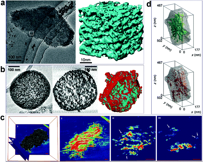 | ||
| Fig. 10 (a) A representative TEM image from a tilt series and the corresponding 3D “volume” reconstructed from the marked area in the image of a hierarchical zeolite Y sample.97 (b) From left to the right are a single TEM image, a cross-section slice cut out from the 3-D volume, and the rendering surface of the volume of an alkaline-treated ZSM-5 crystal.98 (c) Reconstructed electron tomographic volume of a meso-ZSM-5 particle and three slices intersected at different regions of the volume. The slices are rendered in a rainbow color scheme, where empty areas are deep blue. In slices II and III, the discrete dots, some of which are indicated by arrows, represent cross-sections of protruding fibers. Scale bars represent 50 nm.25 (d) Distribution of “open” (green) and ‘‘closed’’ mesopores (red) in a hierarchical zeolite Y crystal, as visualized by volume-rendered 3D representations.99 Reprinted with permission from ref. 98 (Copyright 2014, Wiley-VCH), ref. 99 (Copyright 2005, American Chemical Society), ref. 25 (Copyright 2016, Wiley-VCH), and ref. 100 (Copyright 2012, Wiley-VCH). | ||
3.2 Differential hysteresis scanning (DHS) approach based on gas sorption
One of the most routine characterizations for porous materials is porosity (surface area, pore size/shape distribution, pore volume) assessment based on nitrogen/argon adsorption isotherms. Different methods and models, such as Brunauer–Emmett–Teller (BET), Barrett–Joyner–Halenda (BJH), t-plot, etc., and the scopes of their applications have been nicely reviewed in previous papers.9,46 In the context of hierarchical zeolites, where the pore connectivity is an important criterion given that isolated (closed) mesopores are less useful for enhancing mass transfer, there is a need to develop methods to evaluate the “quality” of the mesopores. It has long and widely been accepted that hysteresis loops in gas sorption isotherms, which are formed due to non-coincidence between capillary condensation and evaporation processes, carry valuable information about the connectivity of mesopores. There are a number of experimental and theoretical studies in the literature aiming to explore pore architecture information from the hysteresis loops.101–104 As illustrated by Klomkliang et al.,103 when the porous structure consists of large cavities with two necks smaller than the critical width Hc that demarcates the mode of evaporation in the cavity, the capillary evaporation of adsorbate in the cavity follows the cavitation mechanism, with the adsorption process taking place from the necks to the cavity and the desorption process from the cavity to the necks. In contrast, the pore blocking mechanism dominates when one of the necks is greater than Hc. They differentiated the two situations from different scanning curves in the hysteresis loops.103 Recently, Kenvin et al.104 applied this method to argon adsorption/desorption isotherms based on nonlocal density functional theory (NLDFT), to characterize complex pore networks in hierarchical zeolites. They used a differential hysteresis scanning (DHS) approach to quantitatively map the amount and sizes of pyramidal, constricted, and occluded mesopores within the hierarchical FAU zeolites. As shown in Fig. 11, the scanning isotherms were acquired by partial saturation of the pore structure followed by a high resolution desorption measurement. During the scanning process, the pore saturation is successively increased in 0.025 p/p0 steps. Subsequently, the incremental change in pore volume was calculated in stepwise cycles. The end of each scanning adsorption branch defines the largest diameter of saturated mesopores. In Fig. 11, for example, point 2 in the isotherm indicates that the pores with sizes smaller than a certain value are saturated, while point 3 indicates the volume of occluded pores that remain saturated after the desorption process. NLDFT models were then applied to extract the size distribution of saturated mesopores and the corresponding volumes from each adsorption/desorption cycle.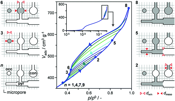 | ||
| Fig. 11 A full DHS measurement for a hierarchical zeolite sample, with 12 incremental desorption/desorption scanning isotherms. As illustrated for selected cycles (points 1–9), the latter selectively fill and empty pyramidal (pyr), constricted (con), and occluded (occ) mesopores of different size (dmeso) depending on the window size (dwin).104 Reprinted with permission from ref. 105. Copyright 2016, Wiley-VCH. | ||
The DHS method has been used to evaluate the “quality” of mesopores generated by various post-treatment routes.104 The results show that the steam-treated sample comprises primarily occluded or constricted mesopores, while mild acid treatment could moderately enhance the formation of pyramidal mesopores, because it preferentially removed the aluminum-rich debris. More severe acid treatment further increases the amount of occluded mesopores, which could be attributed to further framework dealumination. In contrast, the alkaline treatment could form a more open mesoporous system, in which the proportion of pyramidal mesopores increases with the harshness of the base treatment. These results suggest that the base treatment leads to a higher degree of mesopore connectivity as compared to the steam- and acid-treatment.104
3.3 Positron annihilation lifetime spectroscopy (PALS)
Positron annihilation lifetime spectroscopy (PALS) is another effective technology to characterize the porosity of hierarchical zeolites. Pérez-Ramírez et al.20,105 applied this method to study the connectivity of the pore network and the mesopore architecture. In this approach, ortho-positronium (o-Ps) could be formed in a solid on positron implantation. o-Ps is long lived enough to diffuse through porous materials, but it will rapidly lose energy in successive collisions with the pore walls. So, the intensity of the o-Ps trapped with a certain lifetime is proportional to the amount of a certain pore size. Among the six lifetime components in the PALS shown in Fig. 12a, two of them with shortest lifetime are not related to the pore structure, but to the rapid decay of para-positronium (p-Ps, 0.125 ns) and free positrons (e+, 0.7 ns). The lifetime of o-Ps in the micropores of ZSM-5 is around 2.6 ns, while the lifetime between 20 and 40 ns is assigned to the o-Ps in mesopores. The o-Ps with the longest lifetime is assigned to the self-annihilation lifetime under vacuum conditions, and this component is associated with the interconnection of the mesopores, where o-Ps can possibly escape outside. They believed that the fractions (measured by intensity) of o-Ps annihilating in mesopores are related to the pore volumes and the interconnectivity. On the basis of PALS data, they indicated that the interconnection of the mesopores in hierarchical zeolite ZSM-5 catalysts determined their lifetime in the reaction of methanol to hydrocarbons (see Fig. 12b and c), namely, catalysts with more positrons decayed under vacuum showed a longer lifetime in the reaction. For example, among the tested samples, Z40-H1 has the largest fraction (0.28) of o-Ps annihilating under vacuum, and accordingly shows the longest lifetime in methanol to hydrocarbon reactions. The rest of the samples follow the same trend. This work demonstrates that it is the quality rather than the absolute amount of the mesopores that determines the performance of hierarchical zeolites in a catalytic process. PALS provides an indirect yet effective way to evaluate the degree of interconnectivity (“quality”) of mesopore networks in zeolite crystals.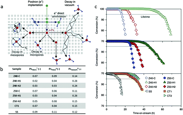 | ||
| Fig. 12 (a) Illustration of the pathway of ortho-positronium (o-Ps) in the hierarchical zeolites. The long-lived o-Ps can diffuse through interconnected mesopores to escape into the vacuum or decay with a lifetime proportional to the pore size. (b) Table of positron annihilation lifetime spectroscopy data. *, ± and # show the relative fractions of o-Ps decaying in micropores, mesopores and the vacuum respectively. (c) The decisive impact of the mesopore “quality” on the catalytic performance of hierarchical zeolites in the conversion of methanol to hydrocarbons.20 Reprinted with permission from ref. 20. Copyright 2014, Nature publishing group. | ||
3.4 Kinetic uptake of probe molecules
The mesoporous network in hierarchical zeolites divides large particles into small domains (crystallites), resulting in reduced diffusion lengths and improved molecular transport. The molecular transport properties of a complex hierarchical structure with disordered and nonuniform mesopores can be reflected by an averaged “diffusion length”, which can be measured by the uptake rate of some kind of adsorbate. The Fickian diffusion model has been developed to calculate the adsorption performance under isothermal conditions, in which the adsorbents (e.g., zeolites) are assumed as spherical crystallites (with the diameter of 2R) without other transport restrictions. According to Fick's second law, the equations to govern the concentration profile of adsorbate inside the zeolite particle are obtained as follows:106,107 | (1) |
The amount of adsorbate adsorbed inside the zeolite can be obtained from eqn (1) by integrating C(r,t) from r = 0 to R,
 | (2) |
For a short contact time (t), eqn (2) can be simplified as follows:107
 | (3) |
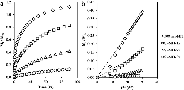 | ||
| Fig. 13 (a) Adsorption of 2,2-dimethylbutane on silylated MFI samples at 298 K and 20 kPa DMB pressure. (b) Amount of 2,2-dimethylbutane adsorbed on silylated MFI samples versus the square root of time at short times on stream. Transport restrictions were introduced externally in the 500 nm-MFI sample to increase the diffusion length by silylating the external surface using tetraethyl orthosilicate. Single-cycle silylation for Si-MFI-1× and 2 (or 3) times silylation for Si-MFI-2× (or Si-MFI-3×).108 Reprinted with permission from ref. 109. Copyright 2015, Elsevier. | ||
The molecular diffusion in hierarchical zeolites has been investigated with this method. Groen et al.109 compared the rate of neopentane uptake in a desilicated (hierarchical) ZSM-5 zeolite and conventional microporous ZSM-5. According to the time required to achieve 50% of the saturation uptake, which was 120 min for conventional ZSM-5 but only 2 min for desilicated ZSM-5, the diffusion rate of neopentane in hierarchical ZSM-5 is approximately 100 times faster than that in the pure microporous ZSM-5. Given that the two materials have the same intrinsic diffusivity, the effective diffusion length of ZSM-5 has been remarkably shortened by the incorporation of mesopores. Pérez-Ramírez et al.110 also compared the molecular transport properties of hierarchical ZSM-5 and conventional ZSM-5, and observed similar phenomena. Using 2,2-dimethylbutane as the probe molecule, Khare et al.108 calculated the diffusion path length of a series of MFI zeolites. Their results showed that the hierarchical self-pillared ZSM-532 has a diffusion length as short as ∼2 nm, which is in good accordance with the single-unit-cell nanosheet structure of this material as revealed by HRTEM. This consistency, in turn, indicates that the kinetic adsorption measurement is a reliable method to determine the transport properties and diffusion lengths of hierarchical zeolites.
4. Summary and outlook
Some typical hierarchical zeolites prepared from direct synthesis routes are summarized in Table 1, along with the templates used and their textural properties, for easy reference. Despite the large number of successful examples, there remain some challenges in directly synthesizing zeolites with hierarchically porous structures. First, the synthesis of an ideal hierarchical zeolite having long-range ordered structures at both meso- and atomic scales, as depicted in Fig. 1, is yet to be achieved. Although the ordering of mesostructures may not be practically important for most applications of zeolites, it is of fundamental importance to address this synthetic challenge. Second, direct synthesis of hierarchical zeolites has been achieved with a limited number of framework types, and the most reported ones are MFI and BEA. This is possibly because the MFI and BEA structures have strong structure-directing effects to be easily induced by multi-ammonium groups grafted on surfactants or polymers. It is highly desirable to synthesize hierarchical zeolites with one-dimensional channels or small ring sizes and potential industrial applications, such as TON, MOR, and DDR. Third, the current synthetic methods cannot achieve controllable mesopore size and pore connectivity, except for the cases of lamellar mesostructures. There is a need to develop new methods to enable systematic control and fine tuning of mesoporosity in zeolites. Fourth, the application of hierarchical zeolites has been mainly focused on catalysis, while their great potential in separation remains unexplored. In fact, the mesopore network in zeolite crystals not only enhances the adsorption kinetics but also provides pathways to entangle with polymers to form mixed-matrixed membranes (MMMs). Our recent study indicates that hierarchical zeolites are more compatible with a polymer matrix than their microporous counterparts, leading to high-quality MMMs with fewer defects (Y. Han, et al., unpublished result). Lastly, the long-term stability of hierarchical zeolites, especially under practical application conditions (e.g., hydrothermal conditions for catalysis), has largely been ignored in the literature, likely because the results are unsatisfactory.| Framework (zeolite) | Templates | Meso-structure | Meso-volume (cm3 g−1) | Reference (year) |
|---|---|---|---|---|
| a PDADMAC: polydiallyldimethylammonium chloride. b PEI: polyethyleneimine, and TEA: triethylamine. c PDAMAB-TPHAB: poly(N1,N1-diallyl-N1-methyl-N6,N6,N6-tripropylhexane-1,6-diamonium bromide). | ||||
| Hard templates + SDAs | ||||
| MFI (ZSM-5) | Carbon black + tetrapropylammonium hydroxide (TPAOH) | Disordered | 1.01 | 59 (1999) |
| 60 (2000) | ||||
| MFI (ZSM-5) | Carbon aerogel + tetrapropylammonium bromide (TPABr) | Disordered | 0.2 | 62 (2003) |
| MFI (Silicalite-1) | 3D ordered carbons + TPAOH | Disordered | 0.69–0.99 | 64 (2008) |
| BEA (Beta) LTA | Tetraethylammonium hydroxide (TEAOH) | 0.55–0.75 | 63 (2011) | |
| FAU | Tetramethylammonium hydroxide (TMAOH) | 0.44–0.75 | ||
| LTL | TMAOH | 0.64 | ||
| 0.82 | ||||
| MFI (ZSM-5) | CMK-3 carbon + TPAOH | Disordered | 0.17 | 61 (2012) |
| Soft templates + SDAs | ||||
| BEA (Beta) | PDADMACa + TEAOH | Disordered | NA | 72 (2006) |
| MOR | Random cationic copolymer | Disordered | 0.37 | 81 (2013) |
| MFI (ZSM-5) | F127, P123 or Brij series + TPAOH | Disordered | 0.56 | 82 (2011) |
| MFI (ZSM-5) | Copolymers of C-PSt-co-P4VP + TPAOH | Disordered | 0.23 | 80 (2012) |
| MFI (ZSM-5) | [(CH3O)3SiC3H6N(CH3)2C16H33]Cl (TPHAC) + TPABr | Disordered | NA | 18 (2006) |
| AFI (AlPO-5) | [(CH3O)3SiC3H6N(CH3)2C16H33]Cl (TPHAC) | Disordered | 0.25 | 70 (2006) |
| AEL (AlPO-11) | 0.26 | |||
| FAU (X) | [(CH3O)3SiC3H6N(CH3)2C16H33]Cl (TPHAC) | Disordered | 0.20 | 74 (2012) |
| MFI (ZSM-5) | Alkyltriethoxysilane (A = propyl, methyl or octyl) | Disordered | 0.307 | 75 (2008) |
| MFI (ZSM-5) | Silane-fuctionalized polyethylenimine + TPAOH | Disordered | 0.07–0.11 | 71 (2006) |
| MFI (TS-1)111 | Triton X-100 + TPAOH | Disordered | 0.09–0.17 | 111 (2016) |
| MSU-MFI | Silylated polypropylene oxide diamine + TPAOH | Disordered | 0.38 | 77 (2009) |
| CHA (SAPO-34) | [(CH3O)3SiC3H6N(CH3)2C18H37]Cl + diethylamine, PEI + PEA2 | Disordered | 0.26 | 73, 78 and 79 (2014, 2015) |
| 0.18 | ||||
| Dual-function surfactants | ||||
| MFI (ZSM-5) | C22H45–N+(CH3)2–C6H12–N+(CH3)2–C6H13 | 2D lamellar | 17, 85 and 88 (2009) | |
| MFI (ZSM-5) | C18H37–N+(CH3)2–C6H12–N+(CH3)2–C6H12–N+(CH3)2–C18H37(Br−)3 | 2D hexagonal | 0.98–1.58 | 16 (2011) |
| BEA (Beta) | C22H45–N+(CH3)2–C6H12–N+(CH3)2–CH2–(C6H4)–CH2–N+(CH3)2–C6H12–N+(CH3)2–[CH2–(C6H4)–CH2–N+(CH3)2–C6H12–N+(CH3)2–C22H45](Br−)2(Cl−)4 | Disordered | 1.49 | 92 (2013) |
| MTW | 0.86 | |||
| MRE | 0.47 | |||
| EU-1 | C18H37–N+(CH3)2–C6H12–N+(CH3)2–C6H12–N+(CH3)2–C18H37(Br−)3 | Disordered | 0.407 | 94 (2016) |
| AFI | C22H45–NH–C6H12–NH2 | 2D lamellar | NA | 93 (2013) |
| AEL | C22H45–N(CH3)–C6H12–N(CH3)2 | 2D lamellar | ||
| ATO | C22H45–N+(CH3)2–C6H12–N+(CH3)2–[CH2–(C6H4)–CH2–N+(CH3)2–C6H12–N+(CH3)2]x–C22H45(OH−)2+2x | Disordered | ||
| MFI (ZSM-5) | C6H5–C6H4–O–C10H20–N+(CH3)2–C6H13(Br−)C6H4–C4H3–O–C10H20–N+(CH3)2–C6H13(Br−) | 2D lamellar | 0.30–0.51 | 21, 22 and 95 (2014) |
| Dual-function polymers | ||||
| BEA (Beta) | PDADMACa | Disordered | 0.76 | 24 (2014) |
| MFI | PDAMAB-TPHABb | Disordered | 0.58 | 25 (2016) |
| BEA (Beta) | PDAMAB-TMHABc | 0.86 | ||
|
MFI (ZSM-5)
BEA (Beta) ATO (AlPO4) |
Polystyrene functionalized with –N+(CH3)2–C6H12–N+(CH3)2–C6H12–N+(CH3)2–C6H13 | Disordered | NA | 23 (2014) |
| Template-free (self-pillared) | ||||
| MFI (ZSM-5) | Tetrabutylphosphonium hydroxide (TBPOH) | House-of-cards-like | 0.6–0.9 | 32 (2012) |
| 96 (2014) | ||||
With the great success achieved over the past years and the recent advances in synthesis and characterization, we have reason to expect that in the near future, novel hierarchical zeolites will be designed and synthesized in a better-controlled manner and their complex architectures will be more thoroughly understood and utilized for a wider range of applications.
References
- M. Moliner, C. Martinez and A. Corma, Angew. Chem., Int. Ed., 2015, 54, 3560–3579 CrossRef CAS PubMed
.
- B. M. Weckhuysen and J. Yu, Chem. Soc. Rev., 2015, 44, 7022–7024 RSC
.
- A. Primo and H. Garcia, Chem. Soc. Rev., 2014, 43, 7548–7561 RSC
.
- M. Yu, R. D. Noble and J. L. Falconer, Acc. Chem. Res., 2011, 44, 1196–1206 CrossRef CAS PubMed
.
- P. Y. Dapsens, C. Mondelli and J. Perez-Ramirez, Chem. Soc. Rev., 2015, 44, 7025–7043 RSC
.
- S. Calero, M. Schenk, D. Dubbeldam, T. L. M. Maesen and B. Smit, J. Catal., 2004, 228, 121–129 CrossRef CAS
.
- J. Jae, G. A. Tompsett, A. J. Foster, K. D. Hammond, S. M. Auerbach, R. F. Lobo and G. W. Huber, J. Catal., 2011, 279, 257–268 CrossRef CAS
.
- M. V. Opanasenko, W. J. Roth and J. Cejka, Catal. Sci. Technol., 2016, 6, 2467–2484 CAS
.
- I. I. Ivanova and E. E. Knyazeva, Chem. Soc. Rev., 2013, 42, 3671–3688 RSC
.
- W. Schwieger, A. G. Machoke, T. Weissenberger, A. Inayat, T. Selvam, M. Klumpp and A. Inayat, Chem. Soc. Rev., 2016, 45, 3353–3376 RSC
.
- J. S. Beck, J. C. Vartuli, W. J. Roth, M. E. Leonowicz, C. T. Kresge, K. D. Schmitt, C. T. W. Chu, D. H. Olson, E. W. Sheppard, S. B. McCullen, J. B. Higgins and J. L. Schlenker, J. Am. Chem. Soc., 1992, 114, 10834–10843 CrossRef CAS
.
- A. Corma, Chem. Rev., 1997, 97, 2373–2419 CrossRef CAS PubMed
.
- Y. Han, D. L. Zhang, L. L. Chng, J. L. Sun, L. Zhao, X. D. Zou and J. Y. Ying, Nat. Chem., 2009, 1, 123–127 CrossRef CAS PubMed
.
- D. Y. Zhao, J. L. Feng, Q. S. Huo, N. Melosh, G. H. Fredrickson, B. F. Chmelka and G. D. Stucky, Science, 1998, 279, 548–552 CrossRef CAS PubMed
.
- X. Fang, Z. Liu, M. F. Hsieh, M. Chen, P. Liu, C. Chen and N. Zheng, ACS Nano, 2012, 6, 4434–4444 CrossRef CAS PubMed
.
- K. Na, C. Jo, J. Kim, K. Cho, J. Jung, Y. Seo, R. J. Messinger, B. F. Chmelka and R. Ryoo, Science, 2011, 333, 328–332 CrossRef CAS PubMed
.
- M. Choi, K. Na, J. Kim, Y. Sakamoto, O. Terasaki and R. Ryoo, Nature, 2009, 461, 246–249 CrossRef CAS PubMed
.
- M. Choi, H. S. Cho, R. Srivastava, C. Venkatesan, D. H. Choi and R. Ryoo, Nat. Mater., 2006, 5, 718–723 CrossRef CAS PubMed
.
- S. Mitchell, A. B. Pinar, J. Kenvin, P. Crivelli, J. Karger and J. Perez-Ramirez, Nat. Commun., 2015, 6, 8633 CrossRef CAS PubMed
.
- M. Milina, S. Mitchell, P. Crivelli, D. Cooke and J. Perez-Ramirez, Nat. Commun., 2014, 5, 3922–3931 Search PubMed
.
- D. Xu, Y. Ma, Z. Jing, L. Han, B. Singh, J. Feng, X. Shen, F. Cao, P. Oleynikov, H. Sun, O. Terasaki and S. Che, Nat. Commun., 2014, 5, 4262–4270 CAS
.
- B. K. Singh, D. Xu, L. Han, J. Ding, Y. Wang and S. Che, Chem. Mater., 2014, 26, 7183–7188 CrossRef CAS
.
- C. Jo, Y. Seo, K. Cho, J. Kim, H. S. Shin, M. Lee, J.-C. Kim, S. O. Kim, J. Y. Lee, H. Ihee and R. Ryoo, Angew. Chem., Int. Ed., 2014, 53, 5117–5121 CAS
.
- J. Zhu, Y. Zhu, L. Zhu, M. Rigutto, A. van der Made, C. Yang, S. Pan, L. Wang, L. Zhu, Y. Jin, Q. Sun, Q. Wu, X. Meng, D. Zhang, Y. Han, J. Li, Y. Chu, A. Zheng, S. Qiu, X. Zheng and F.-S. Xiao, J. Am. Chem. Soc., 2014, 136, 2503–2510 CrossRef CAS PubMed
.
- Q. W. Tian, Z. H. Liu, Y. H. Zhu, X. L. Dong, Y. Saih, J. M. Basset, M. Sun, W. Xu, L. K. Zhu, D. L. Zhang, J. F. Huang, X. J. Meng, F. S. Xiao and Y. Han, Adv. Funct. Mater., 2016, 26, 1881–1891 CrossRef CAS
.
- C. M. A. Parlett, K. Wilson and A. F. Lee, Chem. Soc. Rev., 2013, 42, 3876–3893 RSC
.
- J. Perez-Ramirez, C. H. Christensen, K. Egeblad, C. H. Christensen and J. C. Groen, Chem. Soc. Rev., 2008, 37, 2530–2542 RSC
.
- M. S. Holm, E. Taarning, K. Egeblad and C. H. Christensen, Catal. Today, 2011, 168, 3–16 CrossRef CAS
.
- M. Firoozi, M. Baghalha and M. Asadi, Catal. Commun., 2009, 10, 1582–1585 CrossRef CAS
.
- L. Tosheva and V. P. Valtchev, Chem. Mater., 2005, 17, 2494–2513 CrossRef CAS
.
- S. C. Larsen, J. Phys. Chem. C, 2007, 111, 18464–18474 CAS
.
- X. Zhang, D. Liu, D. Xu, S. Asahina, K. A. Cychosz, K. V. Agrawal, Y. Al Wahedi, A. Bhan, S. Al Hashimi, O. Terasaki, M. Thommes and M. Tsapatsis, Science, 2012, 336, 1684–1687 CrossRef CAS PubMed
.
- D. P. Serrano, J. M. Escola and P. Pizarro, Chem. Soc. Rev., 2013, 42, 4004–4035 RSC
.
- L. H. Chen, X. Y. Li, J. C. Rooke, Y. H. Zhang, X. Y. Yang, Y. Tang, F. S. Xiao and B. L. Su, J. Mater. Chem., 2012, 22, 17381–17403 RSC
.
- L. Wang, J. Zhang, X. Yi, A. Zheng, F. Deng, C. Chen, Y. Ji, F. Liu, X. Meng and F.-S. Xiao, ACS Catal., 2015, 5, 2727–2734 CrossRef CAS
.
- R. Khare, D. Millar and A. Bhan, J. Catal., 2015, 321, 23–31 CrossRef CAS
.
- Z. Liu, X. Dong, Y. Zhu, A.-H. Emwas, D. Zhang, Q. Tian and Y. Han, ACS Catal., 2015, 5, 5837–5845 CrossRef CAS
.
- F. L. Bleken, K. Barbera, F. Bonino, U. Olsbye, K. P. Lillerud, S. Bordiga, P. Beato, T. V. W. Janssens and S. Svelle, J. Catal., 2013, 307, 62–73 CrossRef CAS
.
- Q. Sun, N. Wang, D. Xi, M. Yang and J. Yu, Chem. Commun., 2014, 50, 6502–6505 RSC
.
- D. Xi, Q. Sun, J. Xu, M. Cho, H. S. Cho, S. Asahina, Y. Li, F. Deng, O. Terasaki and J. Yu, J. Mater. Chem. A, 2014, 2, 17994–18004 CAS
.
- B. Besser, H. A. Tajiri, G. Mikolajczyk, J. Mollmer, T. C. Schumacher, S. Odenbach, R. Glaser, S. Kroll and K. Rezwan, ACS Appl. Mater. Interfaces, 2016, 8, 3277–3286 CAS
.
- J. Xu, X. Zha, Y. Wu, Q. Ke and W. Yu, Chem. Commun., 2016, 52, 6367–6370 RSC
.
- J.-Y. Kim, J. Kim, S.-T. Yang and W.-S. Ahn, Fuel, 2013, 108, 515–520 CrossRef CAS
.
- W.-G. Kim, X. Zhang, J. S. Lee, M. Tsapatsis and S. Nair, ACS Nano, 2012, 6, 9978–9988 CrossRef CAS PubMed
.
- D. P. Serrano, J. M. Escola and P. Pizarro, Chem. Soc. Rev., 2013, 42, 4004–4035 RSC
.
- D. Verboekend, N. Nuttens, R. Locus, J. Van Aelst, P. Verolme, J. C. Groen, J. Perez-Ramirez and B. F. Sels, Chem. Soc. Rev., 2016, 45, 3331–3352 RSC
.
- X. Y. Yang, L. H. Chen, Y. Li, J. C. Rooke, C. Sanchez and B. L. Su, Chem. Soc. Rev., 2017, 46, 481–558 RSC
.
- L.-H. Chen, X.-Y. Li, J. C. Rooke, Y.-H. Zhang, X.-Y. Yang, Y. Tang, F.-S. Xiao and B.-L. Su, J. Mater. Chem., 2012, 22, 17381 RSC
.
- J. Perez-Ramirez, C. H. Christensen, K. Egeblad, C. H. Christensen and J. C. Groen, Chem. Soc. Rev., 2008, 37, 2530–2542 RSC
.
- V. Valtchev, G. Majano, S. Mintova and J. Perez-Ramirez, Chem. Soc. Rev., 2013, 42, 263–290 RSC
.
- A. Zukal, V. Patzelova and U. Lohse, Zeolite, 1986, 6, 133–136 CrossRef CAS
.
- E. T. C. Vogt and B. M. Weckhuysen, Chem. Soc. Rev., 2015, 44, 7342–7370 RSC
.
- R. A. Beyerlein, C. Choi-Feng, J. B. Hall, B. J. Huggins and G. J. Ray, Top. Catal., 1997, 4, 27–42 CrossRef CAS
.
- S. van Donk, A. H. Janssen, J. H. Bitter and K. P. de Jong, Catal. Rev., 2003, 45, 297–319 CAS
.
- D. Verboekend, T. C. Keller, S. Mitchell and J. Pérez-Ramírez, Adv. Funct. Mater., 2013, 23, 1923–1934 CrossRef CAS
.
- M. Ogura, S.-Y. Shinomiya, J. Tateno, Y. Nara, E. Kikuchi and M. Matsukata, Chem. Lett., 2000, 882–883 CrossRef CAS
.
- X. Chen, D. Xi, Q. Sun, N. Wang, Z. Dai, D. Fan, V. Valtchev and J. Yu, Microporous Mesoporous Mater., 2016, 234, 401–408 CrossRef CAS
.
- C. Madsen and C. J. H. Jacobsen, Chem. Commun., 1999, 673–674 RSC
.
- C. J. H. Jacobsen, C. Madsen, J. Houzvicka, I. Schmidt and A. Carlsson, J. Am. Chem. Soc., 2000, 122, 7116–7117 CrossRef CAS
.
- H. S. Cho and R. Ryoo, Microporous Mesoporous Mater., 2012, 151, 107–112 CrossRef CAS
.
- Y. Tao, H. Kanoh and K. Kaneko, J. Am. Chem. Soc., 2003, 125, 6044–6045 CrossRef CAS PubMed
.
- H. Chen, J. Wydra, X. Zhang, P.-S. Lee, Z. Wang, W. Fan and M. Tsapatsis, J. Am. Chem. Soc., 2011, 133, 12390–12393 CrossRef CAS PubMed
.
- W. Fan, M. A. Snyder, S. Kumar, P.-S. Lee, W. C. Yoo, A. V. McCormick, R. Lee Penn, A. Stein and M. Tsapatsis, Nat. Mater., 2008, 7, 984–991 CrossRef CAS PubMed
.
- R. J. White, A. Fischer, C. Goebel and A. Thomas, J. Am. Chem. Soc., 2014, 136, 2715–2718 CrossRef CAS PubMed
.
- H. Zhu, Z. Liu, Y. Wang, D. Kong, X. Yuan and Z. Xie, Chem. Mater., 2008, 20, 1134–1139 CrossRef CAS
.
- A. G. Machoke, A. M. Beltran, A. Inayat, B. Winter, T. Weissenberger, N. Kruse, R. Guttel, E. Spiecker and W. Schwieger, Adv. Mater., 2015, 27, 1066–1070 CrossRef CAS PubMed
.
- B. T. Holland, L. Abrams and A. Stein, J. Am. Chem. Soc., 1999, 121, 4308–4309 CrossRef CAS
.
- K. Moller and T. Bein, Chem. Soc. Rev., 2013, 42, 3689–3707 RSC
.
- M. Choi, R. Srivastava and R. Ryoo, Chem. Commun., 2006, 4380–4382 RSC
.
- H. Wang and T. J. Pinnavaia, Angew. Chem., Int. Ed., 2006, 45, 7603–7606 CrossRef CAS PubMed
.
- F.-S. Xiao, L. Wang, C. Yin, K. Lin, Y. Di, J. Li, R. Xu, D. S. Su, R. Schlögl, T. Yokoi and T. Tatsumi, Angew. Chem., Int. Ed., 2006, 45, 3090–3093 CrossRef CAS PubMed
.
- F. Wang, L. Sun, C. Chen, Z. Chen, Z. Zhang, G. Wei and X. Jiang, RSC Adv., 2014, 4, 46093–46096 RSC
.
- K. Cho, H. S. Cho, L.-C. de Ménorval and R. Ryoo, Chem. Mater., 2009, 21, 5664–5673 CrossRef CAS
.
- A. Inayat, I. Knoke, E. Spiecker and W. Schwieger, Angew. Chem., Int. Ed., 2012, 51, 1962–1965 CrossRef CAS PubMed
.
- R. Srivastava, N. Iwasa, S. Fujita and M. Arai, Chem. – Eur. J., 2008, 14, 9507–9511 CrossRef CAS PubMed
.
- D. H. Park, S. S. Kim, H. Wang, T. J. Pinnavaia, M. C. Papapetrou, A. A. Lappas and K. S. Triantafyllidis, Angew. Chem., 2009, 48, 7645–7648 CrossRef CAS PubMed
.
- P. Wang, D. Yang, J. Hu, J. A. Xu and G. Lu, Catal. Today, 2013, 212, 62.e1–62.e8 CAS
.
- C. Wang, M. Yang, P. Tian, S. Xu, Y. Yang, D. Wang, Y. Yuan and Z. Liu, J. Mater. Chem. A, 2015, 3, 5608–5616 CAS
.
- F. Liu, T. Willhammar, L. Wang, L. Zhu, Q. Sun, X. Meng, W. Carrillo-Cabrera, X. Zou and F.-S. Xiao, J. Am. Chem. Soc., 2012, 134, 4557–4560 CrossRef CAS PubMed
.
- T. Tang, L. Zhang, W. Fu, Y. Ma, J. Xu, J. Jiang, G. Fang and F.-S. Xiao, J. Am. Chem. Soc., 2013, 135, 11437–11440 CrossRef CAS PubMed
.
- J. Zhou, Z. Hua, Z. Liu, W. Wu, Y. Zhu and J. Shi, ACS Catal., 2011, 1, 287–291 CrossRef CAS
.
- S. Du, Q. Sun, N. Wang, X. Chen, M. Jia and J. Yu, J. Mater. Chem. A, 2017, 5, 7992–7998 CAS
.
- M. Choi, K. Na, J. Kim, Y. Sakamoto, O. Terasaki and R. Ryoo, Nature, 2009, 461, 246–249 CrossRef CAS PubMed
.
- K. Na, M. Choi, W. Park, Y. Sakamoto, O. Terasaki and R. Ryoo, J. Am. Chem. Soc., 2010, 132, 4169–4177 CrossRef CAS PubMed
.
- K. Na, C. Jo, J. Kim, K. Cho, J. Jung, Y. Seo, R. J. Messinger, B. F. Chmelka and R. Ryoo, Science, 2011, 333, 328–332 CrossRef CAS PubMed
.
- K. Na, W. Park, Y. Seo and R. Ryoo, Chem. Mater., 2011, 23, 1273–1279 CrossRef CAS
.
- W. Park, D. Yu, K. Na, K. E. Jelfs, B. Slater, Y. Sakamoto and R. Ryoo, Chem. Mater., 2011, 23, 5131–5137 CrossRef CAS
.
- K. Cho, K. Na, J. Kim, O. Terasaki and R. Ryoo, Chem. Mater., 2012, 24, 2733–2738 CrossRef CAS
.
- J. Jung, C. Jo, K. Cho and R. Ryoo, J. Mater. Chem., 2012, 22, 4637 RSC
.
- C. Jo, J. Jung, H. S. Shin, J. Kim and R. Ryoo, Angew. Chem., Int. Ed., 2013, 52, 10014–10017 CrossRef CAS PubMed
.
- W. Kim, J.-C. Kim, J. Kim, Y. Seo and R. Ryoo, ACS Catal., 2013, 3, 192–195 CrossRef CAS
.
- Y. Seo, S. Lee, C. Jo and R. Ryoo, J. Am. Chem. Soc., 2013, 135, 8806–8809 CrossRef CAS PubMed
.
- F. M. Mota, P. Eliášová, J. Jung and R. Ryoo, Catal. Sci. Technol., 2016, 6, 2735–2741 CAS
.
- D. Xu, Z. Jing, F. Cao, H. Sun and S. Che, Chem. Mater., 2014, 26, 4612–4619 CrossRef CAS
.
- D. Xu, G. R. Swindlehurst, H. Wu, D. H. Olson, X. Zhang and M. Tsapatsis, Adv. Funct. Mater., 2014, 24, 201–208 CrossRef CAS
.
- M. Khaleel, A. J. Wagner, K. A. Mkhoyan and M. Tsapatsis, Angew. Chem., Int. Ed., 2014, 53, 9456–9461 CrossRef CAS PubMed
.
- J. Garcia-Martinez, C. H. Xiao, K. A. Cychosz, K. H. Li, W. Wan, X. D. Zou and M. Thommes, ChemCatChem, 2014, 6, 3110–3115 CrossRef CAS
.
- J. C. Groen, T. Bach, U. Ziese, A. M. Paulaime-van Donk, K. P. de Jong, J. A. Moulijn and J. Perez-Ramirez, J. Am. Chem. Soc., 2005, 127, 10792–10793 CrossRef CAS PubMed
.
- J. Zecevic, C. J. Gommes, H. Friedrich, P. E. de Jongh and K. P. de Jong, Angew. Chem., Int. Ed., 2012, 51, 4213–4217 CrossRef CAS PubMed
.
- Y. Wei, T. E. Parmentier, K. P. de Jong and J. Zecevic, Chem. Soc. Rev., 2015, 44, 7234–7261 RSC
.
- K. Morishige and M. Shikimi, J. Chem. Phys., 1998, 108, 7821–7824 CrossRef CAS
.
- G. A. Tompsett, L. Krogh, D. W. Griffin and W. C. Conner, Langmuir, 2005, 21, 8214–8225 CrossRef CAS PubMed
.
- N. Klomkliang, D. D. Do and D. Nicholson, J. Phys. Chem. C, 2015, 119, 9355–9363 CAS
.
- J. Kenvin, S. Mitchell, M. Sterling, R. Warringham, T. C. Keller, P. Crivelli, J. Jagiello and J. Pérez-Ramírez, Adv. Funct. Mater., 2016, 26, 5621–5630 CrossRef CAS
.
- R. Warringham, L. Gerchow, A. Zubiaga, D. Cooke, P. Crivelli, S. Mitchell and J. Perez-Ramirez, J. Phys. Chem. C, 2016, 120, 25451–25461 CAS
.
-
J. Crank, The Mathematics of Diffusion, Clarendon Press, Oxford, 2nd edn, 1975 Search PubMed
.
-
J. Kärger, D. M. Ruthven and D. N. Theodorou, Diffusion in Nanoporous Materials, Wiley-VCH, Weinheim, 2012, pp. 143–189 Search PubMed
.
- R. Khare and A. Bhan, J. Catal., 2015, 329, 218–228 CrossRef CAS
.
- J. C. Groen, W. Zhu, S. Brouwer, S. J. Huynink, F. Kapteijn, J. A. Moulijn and J. Perez-Ramirez, J. Am. Chem. Soc., 2007, 129, 355–360 CrossRef CAS PubMed
.
- J. Pérez-Ramírez, D. Verboekend, A. Bonilla and S. Abelló, Adv. Funct. Mater., 2009, 19, 3972–3979 CrossRef
.
- S. Du, F. Li, Q. Sun, N. Wang, M. Jia and J. Yu, Chem. Commun., 2016, 52, 3368–3371 RSC
.
| This journal is © the Partner Organisations 2017 |


